EP3088090B1 - Dispositif de laquage et procédé de laquage d'une surface extérieure d'un objet laqué - Google Patents
Dispositif de laquage et procédé de laquage d'une surface extérieure d'un objet laqué Download PDFInfo
- Publication number
- EP3088090B1 EP3088090B1 EP15165965.3A EP15165965A EP3088090B1 EP 3088090 B1 EP3088090 B1 EP 3088090B1 EP 15165965 A EP15165965 A EP 15165965A EP 3088090 B1 EP3088090 B1 EP 3088090B1
- Authority
- EP
- European Patent Office
- Prior art keywords
- coating
- discharge
- item
- coated
- paint
- Prior art date
- Legal status (The legal status is an assumption and is not a legal conclusion. Google has not performed a legal analysis and makes no representation as to the accuracy of the status listed.)
- Active
Links
Images

Classifications
-
- B—PERFORMING OPERATIONS; TRANSPORTING
- B05—SPRAYING OR ATOMISING IN GENERAL; APPLYING FLUENT MATERIALS TO SURFACES, IN GENERAL
- B05B—SPRAYING APPARATUS; ATOMISING APPARATUS; NOZZLES
- B05B13/00—Machines or plants for applying liquids or other fluent materials to surfaces of objects or other work by spraying, not covered by groups B05B1/00 - B05B11/00
- B05B13/02—Means for supporting work; Arrangement or mounting of spray heads; Adaptation or arrangement of means for feeding work
- B05B13/0221—Means for supporting work; Arrangement or mounting of spray heads; Adaptation or arrangement of means for feeding work characterised by the means for moving or conveying the objects or other work, e.g. conveyor belts
- B05B13/0242—Means for supporting work; Arrangement or mounting of spray heads; Adaptation or arrangement of means for feeding work characterised by the means for moving or conveying the objects or other work, e.g. conveyor belts the objects being individually presented to the spray heads by a rotating element, e.g. turntable
-
- B—PERFORMING OPERATIONS; TRANSPORTING
- B05—SPRAYING OR ATOMISING IN GENERAL; APPLYING FLUENT MATERIALS TO SURFACES, IN GENERAL
- B05D—PROCESSES FOR APPLYING FLUENT MATERIALS TO SURFACES, IN GENERAL
- B05D1/00—Processes for applying liquids or other fluent materials
- B05D1/02—Processes for applying liquids or other fluent materials performed by spraying
-
- B—PERFORMING OPERATIONS; TRANSPORTING
- B05—SPRAYING OR ATOMISING IN GENERAL; APPLYING FLUENT MATERIALS TO SURFACES, IN GENERAL
- B05B—SPRAYING APPARATUS; ATOMISING APPARATUS; NOZZLES
- B05B13/00—Machines or plants for applying liquids or other fluent materials to surfaces of objects or other work by spraying, not covered by groups B05B1/00 - B05B11/00
- B05B13/02—Means for supporting work; Arrangement or mounting of spray heads; Adaptation or arrangement of means for feeding work
- B05B13/0221—Means for supporting work; Arrangement or mounting of spray heads; Adaptation or arrangement of means for feeding work characterised by the means for moving or conveying the objects or other work, e.g. conveyor belts
-
- B—PERFORMING OPERATIONS; TRANSPORTING
- B05—SPRAYING OR ATOMISING IN GENERAL; APPLYING FLUENT MATERIALS TO SURFACES, IN GENERAL
- B05C—APPARATUS FOR APPLYING FLUENT MATERIALS TO SURFACES, IN GENERAL
- B05C13/00—Means for manipulating or holding work, e.g. for separate articles
- B05C13/02—Means for manipulating or holding work, e.g. for separate articles for particular articles
- B05C13/025—Means for manipulating or holding work, e.g. for separate articles for particular articles relatively small cylindrical objects, e.g. cans, bottles
-
- B—PERFORMING OPERATIONS; TRANSPORTING
- B05—SPRAYING OR ATOMISING IN GENERAL; APPLYING FLUENT MATERIALS TO SURFACES, IN GENERAL
- B05C—APPARATUS FOR APPLYING FLUENT MATERIALS TO SURFACES, IN GENERAL
- B05C5/00—Apparatus in which liquid or other fluent material is projected, poured or allowed to flow on to the surface of the work
- B05C5/02—Apparatus in which liquid or other fluent material is projected, poured or allowed to flow on to the surface of the work the liquid or other fluent material being discharged through an outlet orifice by pressure, e.g. from an outlet device in contact or almost in contact, with the work
- B05C5/027—Coating heads with several outlets, e.g. aligned transversally to the moving direction of a web to be coated
- B05C5/0275—Coating heads with several outlets, e.g. aligned transversally to the moving direction of a web to be coated flow controlled, e.g. by a valve
- B05C5/0279—Coating heads with several outlets, e.g. aligned transversally to the moving direction of a web to be coated flow controlled, e.g. by a valve independently, e.g. individually, flow controlled
-
- B—PERFORMING OPERATIONS; TRANSPORTING
- B05—SPRAYING OR ATOMISING IN GENERAL; APPLYING FLUENT MATERIALS TO SURFACES, IN GENERAL
- B05C—APPARATUS FOR APPLYING FLUENT MATERIALS TO SURFACES, IN GENERAL
- B05C5/00—Apparatus in which liquid or other fluent material is projected, poured or allowed to flow on to the surface of the work
- B05C5/02—Apparatus in which liquid or other fluent material is projected, poured or allowed to flow on to the surface of the work the liquid or other fluent material being discharged through an outlet orifice by pressure, e.g. from an outlet device in contact or almost in contact, with the work
- B05C5/0295—Floating coating heads or nozzles
-
- B—PERFORMING OPERATIONS; TRANSPORTING
- B41—PRINTING; LINING MACHINES; TYPEWRITERS; STAMPS
- B41F—PRINTING MACHINES OR PRESSES
- B41F17/00—Printing apparatus or machines of special types or for particular purposes, not otherwise provided for
- B41F17/08—Printing apparatus or machines of special types or for particular purposes, not otherwise provided for for printing on filamentary or elongated articles, or on articles with cylindrical surfaces
- B41F17/14—Printing apparatus or machines of special types or for particular purposes, not otherwise provided for for printing on filamentary or elongated articles, or on articles with cylindrical surfaces on articles of finite length
- B41F17/20—Printing apparatus or machines of special types or for particular purposes, not otherwise provided for for printing on filamentary or elongated articles, or on articles with cylindrical surfaces on articles of finite length on articles of uniform cross-section, e.g. pencils, rulers, resistors
- B41F17/22—Printing apparatus or machines of special types or for particular purposes, not otherwise provided for for printing on filamentary or elongated articles, or on articles with cylindrical surfaces on articles of finite length on articles of uniform cross-section, e.g. pencils, rulers, resistors by rolling contact
-
- B—PERFORMING OPERATIONS; TRANSPORTING
- B41—PRINTING; LINING MACHINES; TYPEWRITERS; STAMPS
- B41F—PRINTING MACHINES OR PRESSES
- B41F19/00—Apparatus or machines for carrying out printing operations combined with other operations
-
- B—PERFORMING OPERATIONS; TRANSPORTING
- B05—SPRAYING OR ATOMISING IN GENERAL; APPLYING FLUENT MATERIALS TO SURFACES, IN GENERAL
- B05C—APPARATUS FOR APPLYING FLUENT MATERIALS TO SURFACES, IN GENERAL
- B05C11/00—Component parts, details or accessories not specifically provided for in groups B05C1/00 - B05C9/00
- B05C11/02—Apparatus for spreading or distributing liquids or other fluent materials already applied to a surface ; Controlling means therefor; Control of the thickness of a coating by spreading or distributing liquids or other fluent materials already applied to the coated surface
- B05C11/06—Apparatus for spreading or distributing liquids or other fluent materials already applied to a surface ; Controlling means therefor; Control of the thickness of a coating by spreading or distributing liquids or other fluent materials already applied to the coated surface with a blast of gas or vapour
Definitions
- the invention relates to a painting device for painting an outer surface of a Lackier réelles, with an output device for providing a continuous or discontinuous paint stream and with a receiving device for receiving and positioning a Lackier réelles opposite to the output device, wherein the output device has a dispensing nozzle and a fluidically communicating connected to the dispensing nozzle paint conveyor includes, which is designed for a pressurized delivery of paint to the dispensing nozzle. Furthermore, the invention relates to a method for painting an outer surface of a Lackier réelles.
- WO 02/20174 A1 discloses an apparatus for holding a substrate that includes a rotating member that is rotatable about a first axis on which a plurality of substrate holders are disposed, the substrate holders being rotatable about a second axis to perform a method in which a substantially uniform coating is applied to a substrate by moving at least one nozzle of a substrate coating station spaced from the substrate holders parallel to the substrate at a predetermined speed and a coating on the substrate, while the substrate holders are rotated about the respective axes.
- An ejection method in which a predetermined amount of liquid is supplied from a liquid reservoir to an ejection valve, wherein prior to starting the ejection of the liquid, pressure is applied to the liquid by means of an urging member based on a predetermined specific value, a pressure near one Discharge port is kept at the predetermined specific value when the liquid ejection is finished, so that a discharge rate of the liquid is kept constant by the discharge port.
- the EP 1 262 244 A2 discloses a device for coating a compressor piston with a rotation support device for rotatably supporting both ends of a piston and a pair of first coating material applicators mounted above the rotation support device so as to be movable up and down, the two coating material applicators each having a first nozzle each applying a coating material on an outer surface of the piston and simultaneously applied coating material to a uniform film thickness, wherein a second coating material applicator is provided having a second nozzle which applies coating material to a bridge portion of the piston ,
- an application device which has a holding section for holding a ceramic lamination body, a nozzle head portion having a plurality of nozzles for ejecting an insulating resin, and a moving means for relatively moving the nozzle head portion along the coating direction, the positions of the openings of the nozzles and / or the diameters of the openings depending on the shapes of the side surfaces of the ceramic lamination body can be varied.
- the US 8,409,666 B2 discloses a bicycle helmet manufacturing method comprising the steps of uniformly coating a base layer of an impact absorbing shell with a resin, coating the base layer with a protective resin layer, applying a pattern to the protective resin layer, and spraying a clear coat on the pattern.
- the JP 2006 248573 A discloses a method for producing a film-bound can body in which a film is first prepared which is subsequently cured with ultraviolet irradiation.
- a film is first prepared which is subsequently cured with ultraviolet irradiation.
- ultraviolet curing ink is ejected from an ink jet printer to adhere the ink to the surface of a substrate, then an adhesive is applied, and heating and drying of the printing layer are performed.
- the printed film is applied to a cylindrical can body to set and cure the printed film on the can body in a subsequent ultraviolet irradiation step.
- the US 5 288 322 A discloses an apparatus for applying a color pattern to textile articles having conveying means comprising a plurality of cylindrical article carriers, and to a plurality of printing stations for printing the articles which are relatively movably mounted to the article carriers, the article carriers being an extension of the respective applied textile article to ensure a reliable fixation of the textile article.
- From the DE 675 593 C1 is a device for applying paint on objects which are rotated about its own axis and about a parallel to its second axis, known, wherein for zonal spraying of the workpieces circumferential bands for limiting the color areas on two opposite sides are arranged such that the Spray jet is limited immediately before the color surface of the two oppositely moving strand of an endless belt to the width of the ink zone to be produced.
- the US 2010/330144 A1 discloses three-dimensional porous tubular scaffolds for cardiovascular, peripheral vascular, nerve conduction, bowel, bile duct, urinary tract, and bone repair / reconstruction, and methods and apparatus for making the same.
- a painting of a Lackier ceremonies which may be in particular an aerosol can blank having a substantially cylindrical outer surface, a paint application to the, preferably previously printed, outer surface by means of a Roll arrangement provided.
- paint from a storage container is first applied to a plurality of rollers aligned parallel to one another, wherein adjacent rollers roll against each other and thereby achieve a homogenization of a paint film.
- An applicator roller is finally in direct contact with the outer surface of the Lackier réelles and applies the paint contact with the outer surface.
- the object of the invention is to provide a painting device and a method for painting an outer surface of a Lackieritess in which a compact structure for the painting and a contactless paint application are guaranteed on the Lackier réelles and operated in a small, enclosed volume of space or performed can occur without this undesirable paint mist.
- the paint delivery device is designed for providing a hydrostatic pressure on the paint and that the outlet nozzles are designed for an output of paint threads in, at least predominantly, in particular exclusively, dependence on the hydrostatic pressure on the paint.
- This refinement of the paint delivery device and the discharge nozzles ensures that the paint can be applied as a paint thread, ie as a compact strand without fogging of paint particles, and applied contactlessly to the outer surface of the paint object.
- no additional fluid, such as compressed air is required to convey the paint from a reservoir to the outlet nozzle (s).
- the discharge process for the paint threads depends essentially on the hydrostatic pressure applied by the paint delivery device to the paint, the viscosity of the paint, which is specified in most paints and can be adjusted by suitable temperature control at a certain interval, on the geometry of the outlet nozzle and from the distance between an orifice of the outlet nozzle and the painting object.
- the lacquer can be discharged from the outlet nozzle without electrostatic or electrodynamic influences on the lacquer, so that the lacquer in this respect does not have to have any special properties, such as a specifiable electrical conductivity.
- a hydrostatic pressure on the paint optionally a pressurized air supply of a reservoir is made or the paint is conveyed to the outlet nozzles with a pumping device.
- the pumping means is arranged away from the outlet nozzles and is designed in particular as a paint delivery pump.
- the invention provides that the outlet nozzles are geometrically designed so that the pressurized paint without an additional conveying fluid, in particular compressed air, emerges in a filamentary form from the outlet nozzle and can be applied to the outer surface of the oppositely arranged Lackier réelles. It is preferably provided that the outlet nozzles are arranged relative to the receiving device, that the exiting paint threads are applied obliquely downwards or in the vertical direction down to the outer surface of the Lackier réelles.
- the receiving device for a rotary mounting of the Lackier ceremoniess is formed about a rotational axis which is aligned transversely to a nozzle axis, which determines a Lackaustrittscardi from the dispensing nozzle.
- a rotational axis which is aligned transversely to a nozzle axis, which determines a Lackaustrittscardi from the dispensing nozzle.
- an advantageous application of paint to the painting object perpendicular / normal and thus parallel to a surface normal of the outer surface of the painting object is ensured.
- a relative movement between the object to be painted and the outlet nozzle can be achieved with the aid of the pivot bearing for the object to be painted around the axis of rotation.
- the painting object embodied by way of example as a cylinder sleeve can be coated with lacquer in an efficient manner on its entire outer surface, which at least substantially corresponds to a cylinder jacket surface. It is particularly advantageous if a cross-section of the painting object is circular and the receiving device is arranged with its axis of rotation relative to the outlet nozzle such that during a rotation of the painting object about the axis of rotation always an at least substantially equal distance between the painting object and outlet nozzle is present.
- the outlet nozzle is exemplarily designed as a circular cylindrical bore in a nozzle plate, wherein a bore axis is identical to the nozzle axis.
- the nozzle axis is aligned normally on an end face of the nozzle plate. It is particularly advantageous if only dispensing nozzles and no paint ejection-influencing, in particular none, fluid outlet nozzles for a pressurized auxiliary fluid, in particular compressed air, are arranged in the nozzle plate.
- the output device is arranged linearly movable relative to the receiving device and comprises a controlled or controlled controllable actuating means for a linear movement along the axis of rotation.
- a superposition of two relative movements can be made during the painting process, by a full-scale application of paint is made possible on the outer surface of the Lackier réelles.
- the first relative movement between the object to be painted and the dispensing nozzle is caused by the rotational movement of the receiving device about the axis of rotation.
- the second relative movement between the object to be painted and the dispensing nozzle takes place through the linear movement of the dispensing device along the axis of rotation.
- the adjusting means may be a fluidic drive or an electric drive, for example a pneumatic cylinder or an electric spindle drive, which is controlled by a suitable control device.
- a plurality of output devices are arranged circumferentially circular to the axis of rotation.
- the dispensing devices can be arranged offset along the axis of rotation to allow an arrangement of dispensing nozzles with respect to the Lackierêt, in which with as few revolutions of the Lackier réelles around the axis of rotation complete or at least provided in a predeterminable coating is possible.
- one or more of the output devices are arranged linearly movable relative to the receiving device and at least two output devices can be moved synchronously or independently of one another along the axis of rotation.
- nozzle axes adjacently arranged output device occupy an acute angle, in particular an angle less than 45 degrees, whereby a particularly compact arrangement of the output devices is made possible.
- the output device comprises a plurality, in particular along a straight line aligned parallel to the axis of rotation, preferably arranged evenly distributed, dispensing nozzles.
- the dispensing nozzles are arranged in a uniform pitch relative to one another, in which the lacquer threads impinging on the outer surface of the lacquer object reliably come into contact with adjacently applied lacquer threads, so that a closed lacquer surface can be created.
- valve device to be formed between the paint delivery device and the delivery nozzle for a temporary interruption of the fluidically communicating connection.
- the valve device which is preferably an electromechanical valve, in particular a solenoid valve, is a highly dynamic influence on the paint flow between the paint conveyor and dispensing nozzle is possible. It is preferably provided that the valve device is arranged immediately upstream of the dispensing nozzle, so that a paint volume that can not be influenced by the switching position or control position of the valve device is kept as low as possible. As a result, an undesirable drop formation in the vicinity of the dispensing nozzle is reduced.
- the valve device can be designed as a needle valve which, at a transition from a paint delivery channel, which can be called a valve chamber, to the dispensing nozzle, engages with a valve needle in a valve seat formed directly on the dispensing nozzle and thus minimizes the volume of paint that can not be influenced.
- a paint delivery channel which can be called a valve chamber
- the paint delivery device and / or the output device and / or the receiving device is assigned a tempering device, in particular a heating device, for a temperature control of the paint and / or the paint object. Since a job of the paint on the outer surface of the Lackier réelles takes place as a paint thread, it is advantageous if the paint thread is easily flowable when hitting the outer surface to wet the largest possible surface area of the outer surface with paint. For this purpose, it is advantageous if the painting object can be heated to a favorable temperature for the paint with a tempering device, in particular a heating device, assigned to the receiving device.
- the paint delivery device and / or the output device is associated with a tempering, with the aid of a temperature of the paint can be kept in a vorgebaren temperature interval to spend a stable paint thread from the dispensing nozzle. This is especially important when a rotational movement of the Lackier réelles is performed around the axis of rotation at a high angular velocity to take this case due to aerodynamic effects no tearing of the paint thread in purchasing, creating a more uneven paint the outer surface of the Lackier réelles would occur.
- the output device is arranged as a processing station on a machine frame and that the machine frame is assigned a plurality of movably mounted receiving devices which are designed for a, in particular discontinuous, transport of painting objects between the processing stations along a, in particular circular section, movement path.
- the machine frame is preferably a machine frame of a printing machine, on which several processing stations are provided for processing the painting object.
- the processing stations also include the intended for painting the Lackieritess output device and additional facilities and / or arrangements that are designed for printing the Lackieritess and / or preparing the Lackieritess on the painting and / or for further processing of the Lackieritess after painting.
- a plurality of receiving devices are provided which are arranged in particular on a common, rotatably mounted, workpiece rotary table, which is provided with a rotary drive. It is preferably provided that the rotary drive carries out a discontinuous movement, in particular a rotary step movement, of the workpiece rotary table and thus of the receiving devices.
- the receiving devices and each recorded on the receiving devices Lackierête along a circular path-shaped movement path between the individual processing stations which are preferably arranged in the same angular pitch and the same radial distance to a rotational axis of the rotary drive, are moved.
- the rotary drive can be, for example, an electric direct drive with a stator fixedly mounted on the machine frame and a rotor rotatably mounted with respect to the stator, in particular integrated in the workpiece rotary table, which performs the desired rotational movement about a preferably vertically oriented axis of rotation by charging with electrical energy
- the receiving devices are preferably designed as mandrels, on which the sleeve-shaped Lackier Consume can be plugged.
- the receiving means may also be formed as a chuck, in which the painting objects are partially inserted and tensioned.
- the output device along the path of movement downstream of a designed as an ink jet printing device printing device is arranged, which is designed for at least partially printing the outer surface of the Lackierêts before performing the painting.
- the printing device is designed to carry out a contactless ink-jet printing process, which can also be referred to as a digital printing process and in which a distribution of printing ink can be determined individually for each painting object.
- the invention provides that the processing stations and the receiving devices are accommodated in a volume of space that is bounded by boundary walls and separated from an environment and in which a constant room temperature and / or a predeterminable overpressure the environment is present. As a result, reproducible conditions for the printing process can be ensured.
- the object of the invention is achieved for a method for decorating an outer surface of a Lackieritess with the following steps: at least partially printing the outer surface of the Lackieritess with a first output device in a formed as an ink jet printing process, pressurized providing a paint from a paint conveyor to a dispensing nozzle of a second Output device and outputting of the paint through the dispensing nozzle on the painting object, wherein during the printing operation and / or during the painting a relative movement between at least one output device and the Lackierêt is carried out by means of a receiving device for the Lackierêt, wherein the relative movement at least one rotation of the Lackieritess to a Includes rotational axis relative to the output device, wherein a radial distance of the output devices to the painting object and an orientation of the Ausgabeinri tions against the object to be painted and a peripheral speed of the object to be painted are adapted to the flow properties of the paint to be processed in such a way that a paint thread is continuously applied to the outer surface of
- the relative movement between a linear movement Paint object and dispensing nozzle along the axis of rotation comprises.
- linear movements are coordinated with a plurality of dispensing devices in such a way that lacquer threads of different dispensing devices are placed crossed on the outer surface of the object to be painted and this causes an advantageous wetting of the outer surface of the object to be painted with the applied lacquer.
- At least one dispensing nozzle is associated with a valve device, which performs a dynamic provision and shutdown of a fluidically communicating connection between paint conveyor and dispensing nozzle, in particular for adaptation to different product lengths of Lackier ceremoniess.
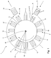
- FIG. 1 schematically illustrated printing machine 1 comprises a rotatable about a rotation axis 2 mounted on a machine frame not shown workpiece rotary table 3 and a plurality, each paired on the workpiece rotary table 3, serving as receiving devices workpiece holders 4.
- the workpiece holders 4 are individually rotatable about rotational axes 5 with not shown drive means stored.
- the workpiece holders 4 are provided for receiving sleeve-shaped objects 6, in particular designed as aerosol can blanks or tube blanks, formed at least substantially with a circular-cylindrical cross-section.
- the workpiece holders 4 are formed as pins on which the hollow body, in particular as a closed hollow cylinder, formed and also referred to as Lackierête objects 6 can be plugged.
- each of the workpiece holders 4 is assigned its own drive motor, which can be controlled separately and is not shown, and which enables a rotational movement of the respective workpiece holder 4 about the respective axis of rotation 5.
- This possibility for, in particular controlled, rotation of the respective workpiece holder 4 is in particular used in carrying out the printing operation and the painting process described in more detail below.
- a plurality of workstations 8 to 18 are arranged, leading to a processing and / or examination of the transported objects 6 are formed. Since it is in the view according to the FIG. 1 is a plan view and the workstations 9 to 17 are usually arranged in the vertical direction above the workpiece holders 4, the workstations are shown 9 to 17 only in dashed lines.
- the work station 8 is a loading station, also referred to as a feed station, on which the cylindrical objects 6 are pushed in pairs onto the workpiece holders 4 by a suitable transport device 19, which is coupled to a conveying system, not shown, for the cylindrical objects 6.
- a neutralization of electrical charges which may be present on an outer surface 25 of the article 6, is provided purely by way of example. Such neutralization is particularly advantageous in plastic articles 6 and may optionally accounts for objects 6 made of metal.
- the workstation 9 comprises a non-illustrated neutralization arrangement, with which the discharge of the article 6 can be performed.
- the neutralization arrangement comprises two electrodes arranged at a distance from each other, to which an electric alternating field is applied in each case by a control device likewise not shown in more detail.
- an electrical voltage and a frequency of the alternating electric field are matched in a manner to the distance of the electrodes, that in the vicinity of the electrodes existing gas, in particular air, can be ionized.
- a charge balance with the electrical charges, which are present on the outer surface 25 of the article 6, take place.
- the now electrically neutral object 6 is then conveyed along the movement path 7 to the subsequent workstation 10.
- the workstation 10 Downstream along the path of movement 7, the workstation 10 is provided following the workstation 9, which is purely an example of a cleaning arrangement.
- the cleaning station is designed as a suction device, which is designed for contactless suction of the outer surface 25 of the article 6.
- the object 6 is now in the course of a further rotational stepping movement of the workpiece rotary table 3 about the rotation axis 2 successively to the work station 12, 13 and 14 moves, which are each purely exemplarily designed as printing stations to each with the help of printing devices 51, as exemplified in the FIG. 2 are shown to be printed.
- the object 6, which is designed as an example with a circular-cylindrical cross-section, rotates about the in-mold FIG. 1 shown rotational axis 5 performs and during the rotational movement by a in the FIG. 2 schematically illustrated printhead 52, which is exemplarily an inkjet printhead, can be printed.
- ink droplets are dispensed from the printhead 52, which is arranged by way of example at a distance of 1 mm to 5 mm from the outer surface of the object 6 and which is driven by a pressure control device 53 with electrical signals.
- the discharge nozzles 52 of the print head 52 which are likewise not illustrated in detail and exit at an exit surface 54, are aligned in such a way that the ink droplets are emitted at least almost perpendicularly to the outer surface 25 of the object 6.
- the work station 15 arranged downstream of the workstation 14 along the movement path 7 is designed as an example as an inspection device and makes it possible to determine a print quality of the print image applied by the printing station 21 to the peripheral surface of the object 6.
- the further workstation 16 is used for further processing of the cylindrical objects 6 by applying a protective lacquer to the printing at least on partial surfaces of the article 6, as described below in connection with FIGS FIGS. 3 to 6 will be described in more detail.
- At the workstation 18 takes place an unloading process in which the cylindrical objects 6 are withdrawn by means of a transport device 20 of the mandrel-like workpiece holders 4 and fed to a non-illustrated further transport system.
- the workpiece turntable 4 performs the stepwise processing of the cylindrical objects 6 at the respective workstations 8 to 18 a rotary step movement by the angle W, in which each paired workpiece holders 4 from one of the respective workstation 8 to 18 opposite position in one of each subsequent workstation 8 to 18 opposite position to be transported.
- the rotational step movement takes place as a sequence of acceleration from standstill, a deceleration from the achieved target speed and a subsequent downtime.
- a non-illustrated drive for the workpiece turntable 3 is designed such that the acceleration and deceleration of the workpiece rotary table 3 are completely freely adjustable over a wide range and the downtime and to the requirements of processing the respective cylindrical objects 6 can be adapted to the workstations 8 to 18.
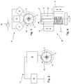
- the in the FIGS. 3 to 6 Painting device shown in more detail is for applying a paint, in particular a clearcoat, formed on the outer surface 25 of the Lackier Communicationss 6 and includes, by way of example, three similarly designed output devices 21, 22, 23, which according to the illustration of FIG. 3 are arranged circular to the axis of rotation 5 of the receiving device 4. As from the representation of FIG. 4 can be removed, the output devices 21, 22, 23 along the axis of rotation 2 of the receiving device 4 are arranged at different positions. By way of example, it is assumed that the output devices 21, 22, 23 can be moved parallel to the axis of rotation 2 by means of adjusting means (not shown), as symbolized by the respective movement arrows.
- the output devices 21, 22, 23 are each formed identically, the structure is in the FIG. 5 shown in more detail and will be described in more detail below.
- Each of the output devices 21, 22, 23 has, by way of example, a number of outlet nozzles 26 on an output surface 24.
- the outlet nozzles 26 are arranged along a straight line, in particular aligned parallel to the axis of rotation 5, in the same pitch, wherein positions of the outlet nozzles 26 in the FIG. 4 are shown schematically at the output device 22 by circles.
- the output means 21, 22, 23 are provided for the provision of lacquer threads on the outer surface 25 of the article 6. For example, as shown in FIG.
- a radial distance of the output devices 21, 22 and 23 to the object 6, an orientation of the output devices 21, 22 and 23 relative to the object 6 and a peripheral speed of the article 6 are adapted to flow properties of the paint to be processed such that one in the FIGS. 4 . 5 and 6 each schematically illustrated paint thread 27 is applied continuously to the outer surface 24 of the article 6.
- a diameter and a flow speed of the lacquer thread 27 are chosen so that when striking the article 6 due to the flow properties of the lacquer a closed lacquer surface on the outer surface 24 of the article 6 can be achieved.
- the exemplary closer, for reasons of clarity, greatly simplified output device 21 comprises a main body 28 which is made of a dimensionally stable material, for example of a metallic material.
- a main body 28 which is made of a dimensionally stable material, for example of a metallic material.
- outlet nozzles 26 are introduced, the nozzle axes 45 are aligned, for example, normal to the output surface 24.
- the magnetic drives 32 are designed as magnetic coil drives having a circular-cylindrical shape and are completely accommodated in the main body 28.
- Each of the magnetic drives 32 comprises a linearly mounted nozzle needle 33, which passes through the base body 28, starting from the magnetic drive 32 and which projects into a valve chamber 34.
- the valve chamber 34 has a larger diameter than the nozzle needle 33, so that between the nozzle needle 33 and the valve body 34, an annular space 35 is formed.
- a supply channel 36 which is in fluidic communication with a supply connection 37.
- a paint delivery device 38 Connected to the supply connection 37 is a paint delivery device 38 which is designed by way of example as a paint pump and which in turn is coupled in fluidic communication with a storage container 39.
- the paint delivery device 38 is electrically connected to a paint control device 31, which is designed to provide electrical energy to the paint delivery device 38 in order to effect a promotion of paint from the reservoir 39 to the outlet nozzles 26.
- the magnetic actuators 32 are also electrically connected to the paint control device 31 and can be selectively controlled by the latter in order to selectively release or block a valve seat 40 provided at the transition between the valve body 34 and the outlet nozzle 26 with the aid of the respective nozzle needle 33.
- a fluidly communicating connection between the reservoir 39 via the supply port 37 and the supply channel 36 and the annular space 35 can be blocked or released to exit nozzle 26.
- FIG. 5 only one outlet nozzle 26 released from the associated nozzle needle 33, so that only there a paint thread 37 can be issued, which can be placed on the outer surface 24 of the oppositely arranged, rotated about the axis of rotation 5 item 6.
- an optional air nozzle 41 which has a slot-shaped air outlet 42 which extends along its axis of rotation 2 at its greatest extent, can be arranged downstream of the output device 21 in the direction of rotation.
- an air jet is emitted perpendicular to the outer surface 25 of the article 6 in order to overcome a surface tension of the coated on the outer surface 25 paint thread 27 so that it spreads as widely as possible on the outer surface 25 and thus an advantageous distribution of the paint is possible.
- the painting control device 31 and the pressure control device 53 are electrically connected, in particular as bus users, and are controlled in a coordinated manner by a higher-level control device (not shown), in particular a programmable logic controller (PLC).
- a higher-level control device not shown
- PLC programmable logic controller
Claims (12)
- Dispositif de laquage pour le laquage d'une surface extérieure (25) d'un objet laqué (6) en forme de douille réalisé comme une ébauche de bombe d'aérosol ou ébauche de tube, avec un dispositif de sortie (21, 22, 23) pour la fourniture d'un courant de laque continu ou discontinu et avec un dispositif de réception (4) pour la réception et le positionnement d'un objet laqué (6) à l'opposé du dispositif de sortie (21, 22, 23), dans lequel le dispositif de sortie (21 22, 23) comprend une buse de sortie (26) et un dispositif de transport de laque (38) raccordé en communiquant fluidiquement avec la base de sortie (26), lequel est réalisé pour un transport sollicité par la pression de laque à la buse de sortie (26), dans lequel le dispositif de transport de laque (38) est réalisé pour une fourniture d'une pression hydrostatique sur la laque et que les buses de sortie (26) sont réalisées pour une sortie de fils de laque (27), en fonction au moins principalement, en particulier exclusivement, de la pression hydrostatique sur la laque, dans lequel le dispositif de sortie (21, 22, 23) est agencé comme poste de travail (8 à 18) au niveau d'un bâti de machine, dans lequel plusieurs dispositifs de réception (4) logés de manière mobile sont associés au bâti de machine, lesquels sont réalisés pour un transport d'objets laqués (6) entre les postes de travail (8 à 18) le long d'une course de déplacement (7), dans lequel le dispositif de sortie (21, 22, 23) est agencé le long de la course de déplacement en aval après un dispositif d'impression (51) réalisé comme dispositif d'impression à jet d'encre, qui est réalisé pour une impression au moins partielle de la surface extérieure (25) de l'objet laqué (6) avant la réalisation du processus de laquage et dans lequel les postes de travail (8 à 18) et les dispositifs de réception (4) sont reçus dans un volume spatial qui est délimité par des parois de délimitation et séparé d'un environnement et dans lequel une température ambiante constante et/ou une surpression prescriptible est présente par rapport à l'environnement.
- Dispositif de laquage selon la revendication 1, caractérisé en ce que le dispositif de réception (4) est réalisé pour un logement rotatif de l'objet laqué (6) autour d'un axe de rotation (5) qui est orienté transversalement à un axe de buse (45) qui détermine un sens de sortie de laque de la buse de sortie (26).
- Dispositif de laquage selon la revendication 1 ou 2, caractérisé en ce que le dispositif de sortie (21, 22, 23) est agencé de manière mobile linéairement par rapport au dispositif de réception (4) et comprend un moyen de réglage actionnable de manière commandée ou régulée pour un mouvement linéaire le long de l'axe de rotation (5).
- Dispositif de laquage selon la revendication 1, 2 ou 3, caractérisé en ce que plusieurs dispositifs de sortie (21, 22, 23) sont agencés de manière à tourner de manière circulaire par rapport à l'axe de rotation (5).
- Dispositif de laquage selon l'une quelconque des revendications précédentes, caractérisé en ce que le dispositif de sortie (21, 22, 23) comprend plusieurs buses de sortie (26) agencées en particulier le long d'une droite orientée parallèlement à l'axe de rotation (5), de préférence dans le même intervalle.
- Dispositif de laquage selon l'une quelconque des revendications précédentes, caractérisé en ce qu'un dispositif de soupape (32, 33, 40) est réalisé pour une interruption temporaire de la liaison communiquant fluidiquement entre le dispositif de transport de laque (38) et la buse de sortie (26).
- Dispositif de laquage selon l'une quelconque des revendications précédentes, caractérisé en ce qu'un dispositif de mise en température, en particulier un dispositif de chauffage, pour une mise en température de la laque et/ou de l'objet laqué (6) est associé au dispositif de transport de laque (38) et/ou au dispositif de sortie (21, 22, 23) et/ou au dispositif de réception (4).
- Dispositif de laquage selon l'une quelconque des revendications précédentes, caractérisé en ce que les dispositifs de réception (4) sont réalisés pour un transport discontinu d'objets laqués (6) entre les postes de travail (8 à 18) le long d'une course de déplacement (7) en forme de section circulaire.
- Procédé de décoration d'une surface extérieure (25) d'un objet laqué (6) en forme de douille réalisé comme une ébauche de bombe d'aérosol ou ébauche de tube avec les étapes suivantes : l'impression au moins partielle de la surface extérieure (25) de l'objet laqué (6) avec un premier dispositif de sortie (51) dans un processus d'impression réalisé comme procédé d'impression à jet d'encre, la fourniture sollicitée par pression d'une laque par un dispositif de transport de laque (38) à une buse de sortie (26) d'un second dispositif de sortie (21, 22, 23) et la sortie de la laque par la buse de sortie (26) sur l'objet laqué (6), dans lequel, pendant le processus d'impression et/ou pendant le processus de laquage, un mouvement relatif entre au moins un dispositif de sortie (21, 22, 23 ; 52) et l'objet laqué (6) est réalisé au moyen d'un dispositif de réception (4) pour l'objet laqué (6), dans lequel le mouvement relatif comprend au moins une rotation de l'objet laqué (6) autour d'un axe de rotation (5) par rapport au dispositif de sortie (21, 22, 23 ; 52), dans lequel une distance radiale des dispositifs de sortie (21, 22, 23 ; 52) par rapport à l'objet laqué (6) ainsi qu'une orientation des dispositifs de sortie (21, 22, 23 ; 56) par rapport à l'objet laqué (6) et une vitesse périphérique de l'objet laqué (6) sont adaptées à des propriétés d'écoulement de la laque à traiter de telle manière qu'un fil de laque (27) soit appliqué en continu sur la surface extérieure (24) de l'objet laqué (6).
- Procédé selon la revendication 9, caractérisé en ce que le mouvement relatif comprend un mouvement linéaire entre l'objet laqué (6) et la buse de sortie (26) le long de l'axe de rotation (5).
- Procédé selon la revendication 9, caractérisé en ce que des mouvements linéaires de plusieurs dispositifs de sortie (21, 22, 23) sont coordonnés de telle manière que des fils de laque (27) des différents dispositifs de sortie (21, 22, 23) soient posés de manière croisée sur la surface extérieure (25) de l'objet laqué (6) et ainsi une réticulation avantageuse de la surface extérieure (25) de l'objet laqué (6) soit provoquée avec la laque appliquée.
- Procédé selon la revendication 9, caractérisé en ce qu'à au moins une buse de sortie (26) est associé un dispositif de soupape (32, 33, 40) qui réalise une fourniture dynamique et l'arrêt d'une liaison communiquant fluidiquement entre le dispositif de transport de laque (38) et la buse de sortie (26), en particulier pour l'adaptation à différentes longueurs de produit de l'objet laqué (6).
Priority Applications (4)
| Application Number | Priority Date | Filing Date | Title |
|---|---|---|---|
| EP15165965.3A EP3088090B1 (fr) | 2015-04-30 | 2015-04-30 | Dispositif de laquage et procédé de laquage d'une surface extérieure d'un objet laqué |
| ES15165965T ES2760000T3 (es) | 2015-04-30 | 2015-04-30 | Equipo de lacado y método para lacar una superficie exterior de un objeto de lacado |
| PL15165965T PL3088090T3 (pl) | 2015-04-30 | 2015-04-30 | Urządzenie lakiernicze i sposób lakierowania powierzchni zewnętrznej obiektu lakierowanego |
| US15/142,633 US20160346806A1 (en) | 2015-04-30 | 2016-04-29 | Coating device and method for coating an outer surface of an item to be coated |
Applications Claiming Priority (1)
| Application Number | Priority Date | Filing Date | Title |
|---|---|---|---|
| EP15165965.3A EP3088090B1 (fr) | 2015-04-30 | 2015-04-30 | Dispositif de laquage et procédé de laquage d'une surface extérieure d'un objet laqué |
Publications (2)
| Publication Number | Publication Date |
|---|---|
| EP3088090A1 EP3088090A1 (fr) | 2016-11-02 |
| EP3088090B1 true EP3088090B1 (fr) | 2019-09-04 |
Family
ID=53039765
Family Applications (1)
| Application Number | Title | Priority Date | Filing Date |
|---|---|---|---|
| EP15165965.3A Active EP3088090B1 (fr) | 2015-04-30 | 2015-04-30 | Dispositif de laquage et procédé de laquage d'une surface extérieure d'un objet laqué |
Country Status (4)
| Country | Link |
|---|---|
| US (1) | US20160346806A1 (fr) |
| EP (1) | EP3088090B1 (fr) |
| ES (1) | ES2760000T3 (fr) |
| PL (1) | PL3088090T3 (fr) |
Families Citing this family (7)
| Publication number | Priority date | Publication date | Assignee | Title |
|---|---|---|---|---|
| CN106925482A (zh) * | 2017-05-03 | 2017-07-07 | 宋伟 | 一种用于弧形木板自动刷漆的设备 |
| ES2813055T3 (es) * | 2018-03-15 | 2021-03-22 | Hinterkopf Gmbh | Equipo de revestimiento y procedimiento para el revestimiento de cuerpos huecos cilíndricos |
| US10953425B2 (en) * | 2018-04-25 | 2021-03-23 | Palo Alto Research Center Incorporated | Methods and systems for collecting droplets of strain hardening viscoelastic fluids in a spray |
| CN109013192B (zh) * | 2018-08-27 | 2023-09-05 | 海南汉地阳光石油化工有限公司 | 一种可调节密封性的密封装置 |
| CN109550653B (zh) * | 2018-12-29 | 2020-05-15 | 库尔兹电子科技(南通)有限公司 | 一种应用于电子元件喷胶的治具 |
| CN111570136A (zh) * | 2020-05-19 | 2020-08-25 | 盐城工学院 | 一种汽车出风口喷涂机构及其使用方法 |
| CN115025922B (zh) * | 2022-06-16 | 2024-02-23 | 重庆工程职业技术学院 | 一种自动化喷涂用工业机器人 |
Family Cites Families (18)
| Publication number | Priority date | Publication date | Assignee | Title |
|---|---|---|---|---|
| CN1088159A (zh) * | 1991-10-02 | 1994-06-22 | 汉纳技术有限公司 | 用于纺织品染色的装置和工艺 |
| US5254164A (en) * | 1992-06-15 | 1993-10-19 | Nordson Corp. | Coating system including indexing turret rotatable in the vertical and horizontal planes about a stationary shaft with loading and unloading of containers and closures from the edges of the turret |
| US5316588A (en) * | 1992-06-16 | 1994-05-31 | Amcol Corporation | System for spraying material on tubing and reclaiming excess material |
| US5354378A (en) * | 1992-07-08 | 1994-10-11 | Nordson Corporation | Slot nozzle apparatus for applying coatings to bottles |
| US6296463B1 (en) * | 1998-04-20 | 2001-10-02 | Nordson Corporation | Segmented metering die for hot melt adhesives or other polymer melts |
| US7815763B2 (en) * | 2001-09-28 | 2010-10-19 | Abbott Laboratories Vascular Enterprises Limited | Porous membranes for medical implants and methods of manufacture |
| EP1155748B1 (fr) * | 1998-12-28 | 2017-04-12 | Musashi Engineering, Inc. | Procede et dispositif d'injection d'une quantite fixe de liquide |
| US6562136B1 (en) * | 2000-09-08 | 2003-05-13 | Surmodics, Inc. | Coating apparatus and method |
| US7504125B1 (en) * | 2001-04-27 | 2009-03-17 | Advanced Cardiovascular Systems, Inc. | System and method for coating implantable devices |
| JP4158962B2 (ja) * | 2001-06-01 | 2008-10-01 | 漢拏空調株式会社 | 圧縮機ピストンコーティング方法 |
| AU2003219916A1 (en) * | 2002-02-22 | 2003-09-09 | University Of Washington | Bioengineered tissue substitutes |
| JP2006142214A (ja) * | 2004-11-19 | 2006-06-08 | Denso Corp | 絶縁樹脂の塗布方法及びその塗布装置 |
| JP4738026B2 (ja) * | 2005-03-10 | 2011-08-03 | 大和製罐株式会社 | 印刷フィルム貼着缶体の製造方法 |
| US7342670B2 (en) * | 2005-10-19 | 2008-03-11 | Labcoat, Ltd. | In-flight drop location verification system |
| WO2008114585A1 (fr) * | 2007-03-20 | 2008-09-25 | Terumo Kabushiki Kaisha | Procédé de revêtement et dispositif de revêtement |
| CN102149859B (zh) * | 2009-06-25 | 2015-08-26 | 北京阿迈特医疗器械有限公司 | 用于制备三维多孔管状支架的方法及设备 |
| US8795761B2 (en) * | 2009-07-02 | 2014-08-05 | Abbott Cardiovascular Systems Inc. | Removing a solvent from a drug-eluting coating |
| US8409666B2 (en) * | 2009-12-03 | 2013-04-02 | Long Huei Helmet Co. | Process to manufacture main body of bike helmet |
-
2015
- 2015-04-30 ES ES15165965T patent/ES2760000T3/es active Active
- 2015-04-30 EP EP15165965.3A patent/EP3088090B1/fr active Active
- 2015-04-30 PL PL15165965T patent/PL3088090T3/pl unknown
-
2016
- 2016-04-29 US US15/142,633 patent/US20160346806A1/en not_active Abandoned
Non-Patent Citations (1)
| Title |
|---|
| None * |
Also Published As
| Publication number | Publication date |
|---|---|
| PL3088090T3 (pl) | 2020-04-30 |
| ES2760000T3 (es) | 2020-05-12 |
| US20160346806A1 (en) | 2016-12-01 |
| EP3088090A1 (fr) | 2016-11-02 |
Similar Documents
| Publication | Publication Date | Title |
|---|---|---|
| EP3088090B1 (fr) | Dispositif de laquage et procédé de laquage d'une surface extérieure d'un objet laqué | |
| EP2705905B1 (fr) | Procédé et dispositif d'illustration et/ou de peinture de la surface d'objets | |
| DE102014116405B4 (de) | Druckvorrichtung sowie Verfahren zur Bedruckung von Behältern | |
| DE102006047382B4 (de) | Vorrichtung zum Lackieren von Werkstücken | |
| EP2043871A1 (fr) | Procédé et dispositif de décoration d'une surface irrégulière d'un objet indéformable | |
| DE102007050490A1 (de) | Vorrichtung und Verfahren zum Bedrucken von Behältern | |
| DE102008061203A1 (de) | Verfahren zum Lackieren einer dreidimensionalen Oberfläche eines Bauteils | |
| EP1806233A1 (fr) | Dispositif pour imprimer sur bouteilles et récipients similaires | |
| DE102011009393A1 (de) | Vorrichtung und Verfahren zum Bedrucken von Behältern | |
| EP3696875B1 (fr) | Procédé d'application d'une couche d'isolation sur un élément de batterie d'un véhicule et une station de revêtement ainsi qu'installation de revêtement destinée à la mise en uvre dudit procédé | |
| EP0897796B1 (fr) | Procédé de fabrication d'un gabarit de sérigraphie et dispositif à cet effet | |
| EP2860036A1 (fr) | Dispositif d'impression, imprimante et procédé de fonctionnement d'un dispositif d'impression | |
| DE102013214934A1 (de) | Vorrichtung und Verfahren zum Direktbedrucken von Behältern | |
| WO2014048880A2 (fr) | Dispositif et procédé de revêtement des alésages de cylindre d'un bloc-moteur | |
| DE102016201140B4 (de) | Verfahren zum Betrieb einer ein Segmentrad aufweisenden Vorrichtung zum Bedrucken von Hohlkörpern | |
| DE19633407A1 (de) | Vorrichtung und Verfahren zum Auftragen von Fotoresist auf nicht ebene Grundkörperflächen für fotolithografische Verfahren | |
| EP2229324A1 (fr) | Procédé d'étiquetage de récipients et poste d'étiquetage | |
| WO2008080449A2 (fr) | Procédé et dispositif de revêtement d'un corps creux | |
| DE102016115031A1 (de) | Verfahren zum Etikettieren von Behältern wie Flaschen | |
| DE4424528A1 (de) | Verfahren zum Bedrucken von Rotationskörpern und Anlage zum Durchführen des Verfahrens | |
| EP3157753B1 (fr) | Procédé et dispositif d'impression de corps creux | |
| WO2013075774A1 (fr) | Dispositif pour appliquer des éléments d'habillage sur des contenants | |
| EP3792060A1 (fr) | Dispositif et procédé d'impression indirecte de pièces pouvant roulées | |
| DE102017205741A1 (de) | Beschichtungseinrichtung, Verfahren zum Herstellen eines beschichteten Bauteils und Kraftfahrzeug | |
| DE202019005563U1 (de) | Beschichtungsstation sowie Beschichtungsanlage zur Durchführung eines Verfahrens zur Aufbringung einer Isolationsschicht auf einer Kfz-Batteriezelle |
Legal Events
| Date | Code | Title | Description |
|---|---|---|---|
| PUAI | Public reference made under article 153(3) epc to a published international application that has entered the european phase |
Free format text: ORIGINAL CODE: 0009012 |
|
| AK | Designated contracting states |
Kind code of ref document: A1 Designated state(s): AL AT BE BG CH CY CZ DE DK EE ES FI FR GB GR HR HU IE IS IT LI LT LU LV MC MK MT NL NO PL PT RO RS SE SI SK SM TR |
|
| AX | Request for extension of the european patent |
Extension state: BA ME |
|
| 17P | Request for examination filed |
Effective date: 20170502 |
|
| RBV | Designated contracting states (corrected) |
Designated state(s): AL AT BE BG CH CY CZ DE DK EE ES FI FR GB GR HR HU IE IS IT LI LT LU LV MC MK MT NL NO PL PT RO RS SE SI SK SM TR |
|
| STAA | Information on the status of an ep patent application or granted ep patent |
Free format text: STATUS: REQUEST FOR EXAMINATION WAS MADE |
|
| TPAC | Observations filed by third parties |
Free format text: ORIGINAL CODE: EPIDOSNTIPA |
|
| STAA | Information on the status of an ep patent application or granted ep patent |
Free format text: STATUS: EXAMINATION IS IN PROGRESS |
|
| 17Q | First examination report despatched |
Effective date: 20171122 |
|
| TPAC | Observations filed by third parties |
Free format text: ORIGINAL CODE: EPIDOSNTIPA |
|
| GRAP | Despatch of communication of intention to grant a patent |
Free format text: ORIGINAL CODE: EPIDOSNIGR1 |
|
| STAA | Information on the status of an ep patent application or granted ep patent |
Free format text: STATUS: GRANT OF PATENT IS INTENDED |
|
| INTG | Intention to grant announced |
Effective date: 20190423 |
|
| GRAS | Grant fee paid |
Free format text: ORIGINAL CODE: EPIDOSNIGR3 |
|
| GRAA | (expected) grant |
Free format text: ORIGINAL CODE: 0009210 |
|
| STAA | Information on the status of an ep patent application or granted ep patent |
Free format text: STATUS: THE PATENT HAS BEEN GRANTED |
|
| AK | Designated contracting states |
Kind code of ref document: B1 Designated state(s): AL AT BE BG CH CY CZ DE DK EE ES FI FR GB GR HR HU IE IS IT LI LT LU LV MC MK MT NL NO PL PT RO RS SE SI SK SM TR |
|
| REG | Reference to a national code |
Ref country code: GB Ref legal event code: FG4D Free format text: NOT ENGLISH |
|
| REG | Reference to a national code |
Ref country code: CH Ref legal event code: EP |
|
| REG | Reference to a national code |
Ref country code: AT Ref legal event code: REF Ref document number: 1174615 Country of ref document: AT Kind code of ref document: T Effective date: 20190915 |
|
| REG | Reference to a national code |
Ref country code: DE Ref legal event code: R096 Ref document number: 502015010212 Country of ref document: DE |
|
| REG | Reference to a national code |
Ref country code: CH Ref legal event code: NV Representative=s name: TROESCH SCHEIDEGGER WERNER AG, CH |
|
| REG | Reference to a national code |
Ref country code: IE Ref legal event code: FG4D Free format text: LANGUAGE OF EP DOCUMENT: GERMAN |
|
| REG | Reference to a national code |
Ref country code: NL Ref legal event code: MP Effective date: 20190904 |
|
| REG | Reference to a national code |
Ref country code: LT Ref legal event code: MG4D |
|
| PG25 | Lapsed in a contracting state [announced via postgrant information from national office to epo] |
Ref country code: HR Free format text: LAPSE BECAUSE OF FAILURE TO SUBMIT A TRANSLATION OF THE DESCRIPTION OR TO PAY THE FEE WITHIN THE PRESCRIBED TIME-LIMIT Effective date: 20190904 Ref country code: LT Free format text: LAPSE BECAUSE OF FAILURE TO SUBMIT A TRANSLATION OF THE DESCRIPTION OR TO PAY THE FEE WITHIN THE PRESCRIBED TIME-LIMIT Effective date: 20190904 Ref country code: NO Free format text: LAPSE BECAUSE OF FAILURE TO SUBMIT A TRANSLATION OF THE DESCRIPTION OR TO PAY THE FEE WITHIN THE PRESCRIBED TIME-LIMIT Effective date: 20191204 Ref country code: BG Free format text: LAPSE BECAUSE OF FAILURE TO SUBMIT A TRANSLATION OF THE DESCRIPTION OR TO PAY THE FEE WITHIN THE PRESCRIBED TIME-LIMIT Effective date: 20191204 Ref country code: FI Free format text: LAPSE BECAUSE OF FAILURE TO SUBMIT A TRANSLATION OF THE DESCRIPTION OR TO PAY THE FEE WITHIN THE PRESCRIBED TIME-LIMIT Effective date: 20190904 Ref country code: SE Free format text: LAPSE BECAUSE OF FAILURE TO SUBMIT A TRANSLATION OF THE DESCRIPTION OR TO PAY THE FEE WITHIN THE PRESCRIBED TIME-LIMIT Effective date: 20190904 |
|
| PG25 | Lapsed in a contracting state [announced via postgrant information from national office to epo] |
Ref country code: RS Free format text: LAPSE BECAUSE OF FAILURE TO SUBMIT A TRANSLATION OF THE DESCRIPTION OR TO PAY THE FEE WITHIN THE PRESCRIBED TIME-LIMIT Effective date: 20190904 Ref country code: GR Free format text: LAPSE BECAUSE OF FAILURE TO SUBMIT A TRANSLATION OF THE DESCRIPTION OR TO PAY THE FEE WITHIN THE PRESCRIBED TIME-LIMIT Effective date: 20191205 Ref country code: AL Free format text: LAPSE BECAUSE OF FAILURE TO SUBMIT A TRANSLATION OF THE DESCRIPTION OR TO PAY THE FEE WITHIN THE PRESCRIBED TIME-LIMIT Effective date: 20190904 Ref country code: LV Free format text: LAPSE BECAUSE OF FAILURE TO SUBMIT A TRANSLATION OF THE DESCRIPTION OR TO PAY THE FEE WITHIN THE PRESCRIBED TIME-LIMIT Effective date: 20190904 |
|
| PG25 | Lapsed in a contracting state [announced via postgrant information from national office to epo] |
Ref country code: NL Free format text: LAPSE BECAUSE OF FAILURE TO SUBMIT A TRANSLATION OF THE DESCRIPTION OR TO PAY THE FEE WITHIN THE PRESCRIBED TIME-LIMIT Effective date: 20190904 Ref country code: EE Free format text: LAPSE BECAUSE OF FAILURE TO SUBMIT A TRANSLATION OF THE DESCRIPTION OR TO PAY THE FEE WITHIN THE PRESCRIBED TIME-LIMIT Effective date: 20190904 Ref country code: RO Free format text: LAPSE BECAUSE OF FAILURE TO SUBMIT A TRANSLATION OF THE DESCRIPTION OR TO PAY THE FEE WITHIN THE PRESCRIBED TIME-LIMIT Effective date: 20190904 Ref country code: PT Free format text: LAPSE BECAUSE OF FAILURE TO SUBMIT A TRANSLATION OF THE DESCRIPTION OR TO PAY THE FEE WITHIN THE PRESCRIBED TIME-LIMIT Effective date: 20200106 |
|
| REG | Reference to a national code |
Ref country code: ES Ref legal event code: FG2A Ref document number: 2760000 Country of ref document: ES Kind code of ref document: T3 Effective date: 20200512 |
|
| PG25 | Lapsed in a contracting state [announced via postgrant information from national office to epo] |
Ref country code: SK Free format text: LAPSE BECAUSE OF FAILURE TO SUBMIT A TRANSLATION OF THE DESCRIPTION OR TO PAY THE FEE WITHIN THE PRESCRIBED TIME-LIMIT Effective date: 20190904 Ref country code: IS Free format text: LAPSE BECAUSE OF FAILURE TO SUBMIT A TRANSLATION OF THE DESCRIPTION OR TO PAY THE FEE WITHIN THE PRESCRIBED TIME-LIMIT Effective date: 20200224 Ref country code: SM Free format text: LAPSE BECAUSE OF FAILURE TO SUBMIT A TRANSLATION OF THE DESCRIPTION OR TO PAY THE FEE WITHIN THE PRESCRIBED TIME-LIMIT Effective date: 20190904 |
|
| REG | Reference to a national code |
Ref country code: DE Ref legal event code: R097 Ref document number: 502015010212 Country of ref document: DE |
|
| PLBE | No opposition filed within time limit |
Free format text: ORIGINAL CODE: 0009261 |
|
| STAA | Information on the status of an ep patent application or granted ep patent |
Free format text: STATUS: NO OPPOSITION FILED WITHIN TIME LIMIT |
|
| PG2D | Information on lapse in contracting state deleted |
Ref country code: IS |
|
| PG25 | Lapsed in a contracting state [announced via postgrant information from national office to epo] |
Ref country code: DK Free format text: LAPSE BECAUSE OF FAILURE TO SUBMIT A TRANSLATION OF THE DESCRIPTION OR TO PAY THE FEE WITHIN THE PRESCRIBED TIME-LIMIT Effective date: 20190904 Ref country code: IS Free format text: LAPSE BECAUSE OF FAILURE TO SUBMIT A TRANSLATION OF THE DESCRIPTION OR TO PAY THE FEE WITHIN THE PRESCRIBED TIME-LIMIT Effective date: 20200105 |
|
| 26N | No opposition filed |
Effective date: 20200605 |
|
| PG25 | Lapsed in a contracting state [announced via postgrant information from national office to epo] |
Ref country code: SI Free format text: LAPSE BECAUSE OF FAILURE TO SUBMIT A TRANSLATION OF THE DESCRIPTION OR TO PAY THE FEE WITHIN THE PRESCRIBED TIME-LIMIT Effective date: 20190904 |
|
| PG25 | Lapsed in a contracting state [announced via postgrant information from national office to epo] |
Ref country code: MC Free format text: LAPSE BECAUSE OF FAILURE TO SUBMIT A TRANSLATION OF THE DESCRIPTION OR TO PAY THE FEE WITHIN THE PRESCRIBED TIME-LIMIT Effective date: 20190904 |
|
| PG25 | Lapsed in a contracting state [announced via postgrant information from national office to epo] |
Ref country code: LU Free format text: LAPSE BECAUSE OF NON-PAYMENT OF DUE FEES Effective date: 20200430 |
|
| REG | Reference to a national code |
Ref country code: BE Ref legal event code: MM Effective date: 20200430 |
|
| PG25 | Lapsed in a contracting state [announced via postgrant information from national office to epo] |
Ref country code: BE Free format text: LAPSE BECAUSE OF NON-PAYMENT OF DUE FEES Effective date: 20200430 |
|
| PG25 | Lapsed in a contracting state [announced via postgrant information from national office to epo] |
Ref country code: IE Free format text: LAPSE BECAUSE OF NON-PAYMENT OF DUE FEES Effective date: 20200430 |
|
| PG25 | Lapsed in a contracting state [announced via postgrant information from national office to epo] |
Ref country code: TR Free format text: LAPSE BECAUSE OF FAILURE TO SUBMIT A TRANSLATION OF THE DESCRIPTION OR TO PAY THE FEE WITHIN THE PRESCRIBED TIME-LIMIT Effective date: 20190904 Ref country code: MT Free format text: LAPSE BECAUSE OF FAILURE TO SUBMIT A TRANSLATION OF THE DESCRIPTION OR TO PAY THE FEE WITHIN THE PRESCRIBED TIME-LIMIT Effective date: 20190904 Ref country code: CY Free format text: LAPSE BECAUSE OF FAILURE TO SUBMIT A TRANSLATION OF THE DESCRIPTION OR TO PAY THE FEE WITHIN THE PRESCRIBED TIME-LIMIT Effective date: 20190904 |
|
| PG25 | Lapsed in a contracting state [announced via postgrant information from national office to epo] |
Ref country code: MK Free format text: LAPSE BECAUSE OF FAILURE TO SUBMIT A TRANSLATION OF THE DESCRIPTION OR TO PAY THE FEE WITHIN THE PRESCRIBED TIME-LIMIT Effective date: 20190904 |
|
| PGFP | Annual fee paid to national office [announced via postgrant information from national office to epo] |
Ref country code: PL Payment date: 20230323 Year of fee payment: 9 |
|
| P01 | Opt-out of the competence of the unified patent court (upc) registered |
Effective date: 20230530 |
|
| PGFP | Annual fee paid to national office [announced via postgrant information from national office to epo] |
Ref country code: IT Payment date: 20230428 Year of fee payment: 9 Ref country code: FR Payment date: 20230417 Year of fee payment: 9 Ref country code: ES Payment date: 20230517 Year of fee payment: 9 Ref country code: DE Payment date: 20230320 Year of fee payment: 9 Ref country code: CZ Payment date: 20230417 Year of fee payment: 9 Ref country code: CH Payment date: 20230502 Year of fee payment: 9 |
|
| PGFP | Annual fee paid to national office [announced via postgrant information from national office to epo] |
Ref country code: AT Payment date: 20230414 Year of fee payment: 9 |
|
| PGFP | Annual fee paid to national office [announced via postgrant information from national office to epo] |
Ref country code: GB Payment date: 20230420 Year of fee payment: 9 |