EP3088090B1 - Varnishing device and method of coating an external surface of a varnishing object - Google Patents
Varnishing device and method of coating an external surface of a varnishing object Download PDFInfo
- Publication number
- EP3088090B1 EP3088090B1 EP15165965.3A EP15165965A EP3088090B1 EP 3088090 B1 EP3088090 B1 EP 3088090B1 EP 15165965 A EP15165965 A EP 15165965A EP 3088090 B1 EP3088090 B1 EP 3088090B1
- Authority
- EP
- European Patent Office
- Prior art keywords
- coating
- discharge
- item
- coated
- paint
- Prior art date
- Legal status (The legal status is an assumption and is not a legal conclusion. Google has not performed a legal analysis and makes no representation as to the accuracy of the status listed.)
- Active
Links
Images

Classifications
-
- B—PERFORMING OPERATIONS; TRANSPORTING
- B05—SPRAYING OR ATOMISING IN GENERAL; APPLYING FLUENT MATERIALS TO SURFACES, IN GENERAL
- B05B—SPRAYING APPARATUS; ATOMISING APPARATUS; NOZZLES
- B05B13/00—Machines or plants for applying liquids or other fluent materials to surfaces of objects or other work by spraying, not covered by groups B05B1/00 - B05B11/00
- B05B13/02—Means for supporting work; Arrangement or mounting of spray heads; Adaptation or arrangement of means for feeding work
- B05B13/0221—Means for supporting work; Arrangement or mounting of spray heads; Adaptation or arrangement of means for feeding work characterised by the means for moving or conveying the objects or other work, e.g. conveyor belts
- B05B13/0242—Means for supporting work; Arrangement or mounting of spray heads; Adaptation or arrangement of means for feeding work characterised by the means for moving or conveying the objects or other work, e.g. conveyor belts the objects being individually presented to the spray heads by a rotating element, e.g. turntable
-
- B—PERFORMING OPERATIONS; TRANSPORTING
- B05—SPRAYING OR ATOMISING IN GENERAL; APPLYING FLUENT MATERIALS TO SURFACES, IN GENERAL
- B05D—PROCESSES FOR APPLYING FLUENT MATERIALS TO SURFACES, IN GENERAL
- B05D1/00—Processes for applying liquids or other fluent materials
- B05D1/02—Processes for applying liquids or other fluent materials performed by spraying
-
- B—PERFORMING OPERATIONS; TRANSPORTING
- B05—SPRAYING OR ATOMISING IN GENERAL; APPLYING FLUENT MATERIALS TO SURFACES, IN GENERAL
- B05B—SPRAYING APPARATUS; ATOMISING APPARATUS; NOZZLES
- B05B13/00—Machines or plants for applying liquids or other fluent materials to surfaces of objects or other work by spraying, not covered by groups B05B1/00 - B05B11/00
- B05B13/02—Means for supporting work; Arrangement or mounting of spray heads; Adaptation or arrangement of means for feeding work
- B05B13/0221—Means for supporting work; Arrangement or mounting of spray heads; Adaptation or arrangement of means for feeding work characterised by the means for moving or conveying the objects or other work, e.g. conveyor belts
-
- B—PERFORMING OPERATIONS; TRANSPORTING
- B05—SPRAYING OR ATOMISING IN GENERAL; APPLYING FLUENT MATERIALS TO SURFACES, IN GENERAL
- B05C—APPARATUS FOR APPLYING FLUENT MATERIALS TO SURFACES, IN GENERAL
- B05C13/00—Means for manipulating or holding work, e.g. for separate articles
- B05C13/02—Means for manipulating or holding work, e.g. for separate articles for particular articles
- B05C13/025—Means for manipulating or holding work, e.g. for separate articles for particular articles relatively small cylindrical objects, e.g. cans, bottles
-
- B—PERFORMING OPERATIONS; TRANSPORTING
- B05—SPRAYING OR ATOMISING IN GENERAL; APPLYING FLUENT MATERIALS TO SURFACES, IN GENERAL
- B05C—APPARATUS FOR APPLYING FLUENT MATERIALS TO SURFACES, IN GENERAL
- B05C5/00—Apparatus in which liquid or other fluent material is projected, poured or allowed to flow on to the surface of the work
- B05C5/02—Apparatus in which liquid or other fluent material is projected, poured or allowed to flow on to the surface of the work the liquid or other fluent material being discharged through an outlet orifice by pressure, e.g. from an outlet device in contact or almost in contact, with the work
- B05C5/027—Coating heads with several outlets, e.g. aligned transversally to the moving direction of a web to be coated
- B05C5/0275—Coating heads with several outlets, e.g. aligned transversally to the moving direction of a web to be coated flow controlled, e.g. by a valve
- B05C5/0279—Coating heads with several outlets, e.g. aligned transversally to the moving direction of a web to be coated flow controlled, e.g. by a valve independently, e.g. individually, flow controlled
-
- B—PERFORMING OPERATIONS; TRANSPORTING
- B05—SPRAYING OR ATOMISING IN GENERAL; APPLYING FLUENT MATERIALS TO SURFACES, IN GENERAL
- B05C—APPARATUS FOR APPLYING FLUENT MATERIALS TO SURFACES, IN GENERAL
- B05C5/00—Apparatus in which liquid or other fluent material is projected, poured or allowed to flow on to the surface of the work
- B05C5/02—Apparatus in which liquid or other fluent material is projected, poured or allowed to flow on to the surface of the work the liquid or other fluent material being discharged through an outlet orifice by pressure, e.g. from an outlet device in contact or almost in contact, with the work
- B05C5/0295—Floating coating heads or nozzles
-
- B—PERFORMING OPERATIONS; TRANSPORTING
- B41—PRINTING; LINING MACHINES; TYPEWRITERS; STAMPS
- B41F—PRINTING MACHINES OR PRESSES
- B41F17/00—Printing apparatus or machines of special types or for particular purposes, not otherwise provided for
- B41F17/08—Printing apparatus or machines of special types or for particular purposes, not otherwise provided for for printing on filamentary or elongated articles, or on articles with cylindrical surfaces
- B41F17/14—Printing apparatus or machines of special types or for particular purposes, not otherwise provided for for printing on filamentary or elongated articles, or on articles with cylindrical surfaces on articles of finite length
- B41F17/20—Printing apparatus or machines of special types or for particular purposes, not otherwise provided for for printing on filamentary or elongated articles, or on articles with cylindrical surfaces on articles of finite length on articles of uniform cross-section, e.g. pencils, rulers, resistors
- B41F17/22—Printing apparatus or machines of special types or for particular purposes, not otherwise provided for for printing on filamentary or elongated articles, or on articles with cylindrical surfaces on articles of finite length on articles of uniform cross-section, e.g. pencils, rulers, resistors by rolling contact
-
- B—PERFORMING OPERATIONS; TRANSPORTING
- B41—PRINTING; LINING MACHINES; TYPEWRITERS; STAMPS
- B41F—PRINTING MACHINES OR PRESSES
- B41F19/00—Apparatus or machines for carrying out printing operations combined with other operations
-
- B—PERFORMING OPERATIONS; TRANSPORTING
- B05—SPRAYING OR ATOMISING IN GENERAL; APPLYING FLUENT MATERIALS TO SURFACES, IN GENERAL
- B05C—APPARATUS FOR APPLYING FLUENT MATERIALS TO SURFACES, IN GENERAL
- B05C11/00—Component parts, details or accessories not specifically provided for in groups B05C1/00 - B05C9/00
- B05C11/02—Apparatus for spreading or distributing liquids or other fluent materials already applied to a surface ; Controlling means therefor; Control of the thickness of a coating by spreading or distributing liquids or other fluent materials already applied to the coated surface
- B05C11/06—Apparatus for spreading or distributing liquids or other fluent materials already applied to a surface ; Controlling means therefor; Control of the thickness of a coating by spreading or distributing liquids or other fluent materials already applied to the coated surface with a blast of gas or vapour
Definitions
- the invention relates to a painting device for painting an outer surface of a Lackier réelles, with an output device for providing a continuous or discontinuous paint stream and with a receiving device for receiving and positioning a Lackier réelles opposite to the output device, wherein the output device has a dispensing nozzle and a fluidically communicating connected to the dispensing nozzle paint conveyor includes, which is designed for a pressurized delivery of paint to the dispensing nozzle. Furthermore, the invention relates to a method for painting an outer surface of a Lackier réelles.
- WO 02/20174 A1 discloses an apparatus for holding a substrate that includes a rotating member that is rotatable about a first axis on which a plurality of substrate holders are disposed, the substrate holders being rotatable about a second axis to perform a method in which a substantially uniform coating is applied to a substrate by moving at least one nozzle of a substrate coating station spaced from the substrate holders parallel to the substrate at a predetermined speed and a coating on the substrate, while the substrate holders are rotated about the respective axes.
- An ejection method in which a predetermined amount of liquid is supplied from a liquid reservoir to an ejection valve, wherein prior to starting the ejection of the liquid, pressure is applied to the liquid by means of an urging member based on a predetermined specific value, a pressure near one Discharge port is kept at the predetermined specific value when the liquid ejection is finished, so that a discharge rate of the liquid is kept constant by the discharge port.
- the EP 1 262 244 A2 discloses a device for coating a compressor piston with a rotation support device for rotatably supporting both ends of a piston and a pair of first coating material applicators mounted above the rotation support device so as to be movable up and down, the two coating material applicators each having a first nozzle each applying a coating material on an outer surface of the piston and simultaneously applied coating material to a uniform film thickness, wherein a second coating material applicator is provided having a second nozzle which applies coating material to a bridge portion of the piston ,
- an application device which has a holding section for holding a ceramic lamination body, a nozzle head portion having a plurality of nozzles for ejecting an insulating resin, and a moving means for relatively moving the nozzle head portion along the coating direction, the positions of the openings of the nozzles and / or the diameters of the openings depending on the shapes of the side surfaces of the ceramic lamination body can be varied.
- the US 8,409,666 B2 discloses a bicycle helmet manufacturing method comprising the steps of uniformly coating a base layer of an impact absorbing shell with a resin, coating the base layer with a protective resin layer, applying a pattern to the protective resin layer, and spraying a clear coat on the pattern.
- the JP 2006 248573 A discloses a method for producing a film-bound can body in which a film is first prepared which is subsequently cured with ultraviolet irradiation.
- a film is first prepared which is subsequently cured with ultraviolet irradiation.
- ultraviolet curing ink is ejected from an ink jet printer to adhere the ink to the surface of a substrate, then an adhesive is applied, and heating and drying of the printing layer are performed.
- the printed film is applied to a cylindrical can body to set and cure the printed film on the can body in a subsequent ultraviolet irradiation step.
- the US 5 288 322 A discloses an apparatus for applying a color pattern to textile articles having conveying means comprising a plurality of cylindrical article carriers, and to a plurality of printing stations for printing the articles which are relatively movably mounted to the article carriers, the article carriers being an extension of the respective applied textile article to ensure a reliable fixation of the textile article.
- From the DE 675 593 C1 is a device for applying paint on objects which are rotated about its own axis and about a parallel to its second axis, known, wherein for zonal spraying of the workpieces circumferential bands for limiting the color areas on two opposite sides are arranged such that the Spray jet is limited immediately before the color surface of the two oppositely moving strand of an endless belt to the width of the ink zone to be produced.
- the US 2010/330144 A1 discloses three-dimensional porous tubular scaffolds for cardiovascular, peripheral vascular, nerve conduction, bowel, bile duct, urinary tract, and bone repair / reconstruction, and methods and apparatus for making the same.
- a painting of a Lackier ceremonies which may be in particular an aerosol can blank having a substantially cylindrical outer surface, a paint application to the, preferably previously printed, outer surface by means of a Roll arrangement provided.
- paint from a storage container is first applied to a plurality of rollers aligned parallel to one another, wherein adjacent rollers roll against each other and thereby achieve a homogenization of a paint film.
- An applicator roller is finally in direct contact with the outer surface of the Lackier réelles and applies the paint contact with the outer surface.
- the object of the invention is to provide a painting device and a method for painting an outer surface of a Lackieritess in which a compact structure for the painting and a contactless paint application are guaranteed on the Lackier réelles and operated in a small, enclosed volume of space or performed can occur without this undesirable paint mist.
- the paint delivery device is designed for providing a hydrostatic pressure on the paint and that the outlet nozzles are designed for an output of paint threads in, at least predominantly, in particular exclusively, dependence on the hydrostatic pressure on the paint.
- This refinement of the paint delivery device and the discharge nozzles ensures that the paint can be applied as a paint thread, ie as a compact strand without fogging of paint particles, and applied contactlessly to the outer surface of the paint object.
- no additional fluid, such as compressed air is required to convey the paint from a reservoir to the outlet nozzle (s).
- the discharge process for the paint threads depends essentially on the hydrostatic pressure applied by the paint delivery device to the paint, the viscosity of the paint, which is specified in most paints and can be adjusted by suitable temperature control at a certain interval, on the geometry of the outlet nozzle and from the distance between an orifice of the outlet nozzle and the painting object.
- the lacquer can be discharged from the outlet nozzle without electrostatic or electrodynamic influences on the lacquer, so that the lacquer in this respect does not have to have any special properties, such as a specifiable electrical conductivity.
- a hydrostatic pressure on the paint optionally a pressurized air supply of a reservoir is made or the paint is conveyed to the outlet nozzles with a pumping device.
- the pumping means is arranged away from the outlet nozzles and is designed in particular as a paint delivery pump.
- the invention provides that the outlet nozzles are geometrically designed so that the pressurized paint without an additional conveying fluid, in particular compressed air, emerges in a filamentary form from the outlet nozzle and can be applied to the outer surface of the oppositely arranged Lackier réelles. It is preferably provided that the outlet nozzles are arranged relative to the receiving device, that the exiting paint threads are applied obliquely downwards or in the vertical direction down to the outer surface of the Lackier réelles.
- the receiving device for a rotary mounting of the Lackier ceremoniess is formed about a rotational axis which is aligned transversely to a nozzle axis, which determines a Lackaustrittscardi from the dispensing nozzle.
- a rotational axis which is aligned transversely to a nozzle axis, which determines a Lackaustrittscardi from the dispensing nozzle.
- an advantageous application of paint to the painting object perpendicular / normal and thus parallel to a surface normal of the outer surface of the painting object is ensured.
- a relative movement between the object to be painted and the outlet nozzle can be achieved with the aid of the pivot bearing for the object to be painted around the axis of rotation.
- the painting object embodied by way of example as a cylinder sleeve can be coated with lacquer in an efficient manner on its entire outer surface, which at least substantially corresponds to a cylinder jacket surface. It is particularly advantageous if a cross-section of the painting object is circular and the receiving device is arranged with its axis of rotation relative to the outlet nozzle such that during a rotation of the painting object about the axis of rotation always an at least substantially equal distance between the painting object and outlet nozzle is present.
- the outlet nozzle is exemplarily designed as a circular cylindrical bore in a nozzle plate, wherein a bore axis is identical to the nozzle axis.
- the nozzle axis is aligned normally on an end face of the nozzle plate. It is particularly advantageous if only dispensing nozzles and no paint ejection-influencing, in particular none, fluid outlet nozzles for a pressurized auxiliary fluid, in particular compressed air, are arranged in the nozzle plate.
- the output device is arranged linearly movable relative to the receiving device and comprises a controlled or controlled controllable actuating means for a linear movement along the axis of rotation.
- a superposition of two relative movements can be made during the painting process, by a full-scale application of paint is made possible on the outer surface of the Lackier réelles.
- the first relative movement between the object to be painted and the dispensing nozzle is caused by the rotational movement of the receiving device about the axis of rotation.
- the second relative movement between the object to be painted and the dispensing nozzle takes place through the linear movement of the dispensing device along the axis of rotation.
- the adjusting means may be a fluidic drive or an electric drive, for example a pneumatic cylinder or an electric spindle drive, which is controlled by a suitable control device.
- a plurality of output devices are arranged circumferentially circular to the axis of rotation.
- the dispensing devices can be arranged offset along the axis of rotation to allow an arrangement of dispensing nozzles with respect to the Lackierêt, in which with as few revolutions of the Lackier réelles around the axis of rotation complete or at least provided in a predeterminable coating is possible.
- one or more of the output devices are arranged linearly movable relative to the receiving device and at least two output devices can be moved synchronously or independently of one another along the axis of rotation.
- nozzle axes adjacently arranged output device occupy an acute angle, in particular an angle less than 45 degrees, whereby a particularly compact arrangement of the output devices is made possible.
- the output device comprises a plurality, in particular along a straight line aligned parallel to the axis of rotation, preferably arranged evenly distributed, dispensing nozzles.
- the dispensing nozzles are arranged in a uniform pitch relative to one another, in which the lacquer threads impinging on the outer surface of the lacquer object reliably come into contact with adjacently applied lacquer threads, so that a closed lacquer surface can be created.
- valve device to be formed between the paint delivery device and the delivery nozzle for a temporary interruption of the fluidically communicating connection.
- the valve device which is preferably an electromechanical valve, in particular a solenoid valve, is a highly dynamic influence on the paint flow between the paint conveyor and dispensing nozzle is possible. It is preferably provided that the valve device is arranged immediately upstream of the dispensing nozzle, so that a paint volume that can not be influenced by the switching position or control position of the valve device is kept as low as possible. As a result, an undesirable drop formation in the vicinity of the dispensing nozzle is reduced.
- the valve device can be designed as a needle valve which, at a transition from a paint delivery channel, which can be called a valve chamber, to the dispensing nozzle, engages with a valve needle in a valve seat formed directly on the dispensing nozzle and thus minimizes the volume of paint that can not be influenced.
- a paint delivery channel which can be called a valve chamber
- the paint delivery device and / or the output device and / or the receiving device is assigned a tempering device, in particular a heating device, for a temperature control of the paint and / or the paint object. Since a job of the paint on the outer surface of the Lackier réelles takes place as a paint thread, it is advantageous if the paint thread is easily flowable when hitting the outer surface to wet the largest possible surface area of the outer surface with paint. For this purpose, it is advantageous if the painting object can be heated to a favorable temperature for the paint with a tempering device, in particular a heating device, assigned to the receiving device.
- the paint delivery device and / or the output device is associated with a tempering, with the aid of a temperature of the paint can be kept in a vorgebaren temperature interval to spend a stable paint thread from the dispensing nozzle. This is especially important when a rotational movement of the Lackier réelles is performed around the axis of rotation at a high angular velocity to take this case due to aerodynamic effects no tearing of the paint thread in purchasing, creating a more uneven paint the outer surface of the Lackier réelles would occur.
- the output device is arranged as a processing station on a machine frame and that the machine frame is assigned a plurality of movably mounted receiving devices which are designed for a, in particular discontinuous, transport of painting objects between the processing stations along a, in particular circular section, movement path.
- the machine frame is preferably a machine frame of a printing machine, on which several processing stations are provided for processing the painting object.
- the processing stations also include the intended for painting the Lackieritess output device and additional facilities and / or arrangements that are designed for printing the Lackieritess and / or preparing the Lackieritess on the painting and / or for further processing of the Lackieritess after painting.
- a plurality of receiving devices are provided which are arranged in particular on a common, rotatably mounted, workpiece rotary table, which is provided with a rotary drive. It is preferably provided that the rotary drive carries out a discontinuous movement, in particular a rotary step movement, of the workpiece rotary table and thus of the receiving devices.
- the receiving devices and each recorded on the receiving devices Lackierête along a circular path-shaped movement path between the individual processing stations which are preferably arranged in the same angular pitch and the same radial distance to a rotational axis of the rotary drive, are moved.
- the rotary drive can be, for example, an electric direct drive with a stator fixedly mounted on the machine frame and a rotor rotatably mounted with respect to the stator, in particular integrated in the workpiece rotary table, which performs the desired rotational movement about a preferably vertically oriented axis of rotation by charging with electrical energy
- the receiving devices are preferably designed as mandrels, on which the sleeve-shaped Lackier Consume can be plugged.
- the receiving means may also be formed as a chuck, in which the painting objects are partially inserted and tensioned.
- the output device along the path of movement downstream of a designed as an ink jet printing device printing device is arranged, which is designed for at least partially printing the outer surface of the Lackierêts before performing the painting.
- the printing device is designed to carry out a contactless ink-jet printing process, which can also be referred to as a digital printing process and in which a distribution of printing ink can be determined individually for each painting object.
- the invention provides that the processing stations and the receiving devices are accommodated in a volume of space that is bounded by boundary walls and separated from an environment and in which a constant room temperature and / or a predeterminable overpressure the environment is present. As a result, reproducible conditions for the printing process can be ensured.
- the object of the invention is achieved for a method for decorating an outer surface of a Lackieritess with the following steps: at least partially printing the outer surface of the Lackieritess with a first output device in a formed as an ink jet printing process, pressurized providing a paint from a paint conveyor to a dispensing nozzle of a second Output device and outputting of the paint through the dispensing nozzle on the painting object, wherein during the printing operation and / or during the painting a relative movement between at least one output device and the Lackierêt is carried out by means of a receiving device for the Lackierêt, wherein the relative movement at least one rotation of the Lackieritess to a Includes rotational axis relative to the output device, wherein a radial distance of the output devices to the painting object and an orientation of the Ausgabeinri tions against the object to be painted and a peripheral speed of the object to be painted are adapted to the flow properties of the paint to be processed in such a way that a paint thread is continuously applied to the outer surface of
- the relative movement between a linear movement Paint object and dispensing nozzle along the axis of rotation comprises.
- linear movements are coordinated with a plurality of dispensing devices in such a way that lacquer threads of different dispensing devices are placed crossed on the outer surface of the object to be painted and this causes an advantageous wetting of the outer surface of the object to be painted with the applied lacquer.
- At least one dispensing nozzle is associated with a valve device, which performs a dynamic provision and shutdown of a fluidically communicating connection between paint conveyor and dispensing nozzle, in particular for adaptation to different product lengths of Lackier ceremoniess.
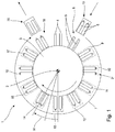
- FIG. 1 schematically illustrated printing machine 1 comprises a rotatable about a rotation axis 2 mounted on a machine frame not shown workpiece rotary table 3 and a plurality, each paired on the workpiece rotary table 3, serving as receiving devices workpiece holders 4.
- the workpiece holders 4 are individually rotatable about rotational axes 5 with not shown drive means stored.
- the workpiece holders 4 are provided for receiving sleeve-shaped objects 6, in particular designed as aerosol can blanks or tube blanks, formed at least substantially with a circular-cylindrical cross-section.
- the workpiece holders 4 are formed as pins on which the hollow body, in particular as a closed hollow cylinder, formed and also referred to as Lackierête objects 6 can be plugged.
- each of the workpiece holders 4 is assigned its own drive motor, which can be controlled separately and is not shown, and which enables a rotational movement of the respective workpiece holder 4 about the respective axis of rotation 5.
- This possibility for, in particular controlled, rotation of the respective workpiece holder 4 is in particular used in carrying out the printing operation and the painting process described in more detail below.
- a plurality of workstations 8 to 18 are arranged, leading to a processing and / or examination of the transported objects 6 are formed. Since it is in the view according to the FIG. 1 is a plan view and the workstations 9 to 17 are usually arranged in the vertical direction above the workpiece holders 4, the workstations are shown 9 to 17 only in dashed lines.
- the work station 8 is a loading station, also referred to as a feed station, on which the cylindrical objects 6 are pushed in pairs onto the workpiece holders 4 by a suitable transport device 19, which is coupled to a conveying system, not shown, for the cylindrical objects 6.
- a neutralization of electrical charges which may be present on an outer surface 25 of the article 6, is provided purely by way of example. Such neutralization is particularly advantageous in plastic articles 6 and may optionally accounts for objects 6 made of metal.
- the workstation 9 comprises a non-illustrated neutralization arrangement, with which the discharge of the article 6 can be performed.
- the neutralization arrangement comprises two electrodes arranged at a distance from each other, to which an electric alternating field is applied in each case by a control device likewise not shown in more detail.
- an electrical voltage and a frequency of the alternating electric field are matched in a manner to the distance of the electrodes, that in the vicinity of the electrodes existing gas, in particular air, can be ionized.
- a charge balance with the electrical charges, which are present on the outer surface 25 of the article 6, take place.
- the now electrically neutral object 6 is then conveyed along the movement path 7 to the subsequent workstation 10.
- the workstation 10 Downstream along the path of movement 7, the workstation 10 is provided following the workstation 9, which is purely an example of a cleaning arrangement.
- the cleaning station is designed as a suction device, which is designed for contactless suction of the outer surface 25 of the article 6.
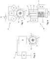
- the object 6 is now in the course of a further rotational stepping movement of the workpiece rotary table 3 about the rotation axis 2 successively to the work station 12, 13 and 14 moves, which are each purely exemplarily designed as printing stations to each with the help of printing devices 51, as exemplified in the FIG. 2 are shown to be printed.
- the object 6, which is designed as an example with a circular-cylindrical cross-section, rotates about the in-mold FIG. 1 shown rotational axis 5 performs and during the rotational movement by a in the FIG. 2 schematically illustrated printhead 52, which is exemplarily an inkjet printhead, can be printed.
- ink droplets are dispensed from the printhead 52, which is arranged by way of example at a distance of 1 mm to 5 mm from the outer surface of the object 6 and which is driven by a pressure control device 53 with electrical signals.
- the discharge nozzles 52 of the print head 52 which are likewise not illustrated in detail and exit at an exit surface 54, are aligned in such a way that the ink droplets are emitted at least almost perpendicularly to the outer surface 25 of the object 6.
- the work station 15 arranged downstream of the workstation 14 along the movement path 7 is designed as an example as an inspection device and makes it possible to determine a print quality of the print image applied by the printing station 21 to the peripheral surface of the object 6.
- the further workstation 16 is used for further processing of the cylindrical objects 6 by applying a protective lacquer to the printing at least on partial surfaces of the article 6, as described below in connection with FIGS FIGS. 3 to 6 will be described in more detail.
- At the workstation 18 takes place an unloading process in which the cylindrical objects 6 are withdrawn by means of a transport device 20 of the mandrel-like workpiece holders 4 and fed to a non-illustrated further transport system.
- the workpiece turntable 4 performs the stepwise processing of the cylindrical objects 6 at the respective workstations 8 to 18 a rotary step movement by the angle W, in which each paired workpiece holders 4 from one of the respective workstation 8 to 18 opposite position in one of each subsequent workstation 8 to 18 opposite position to be transported.
- the rotational step movement takes place as a sequence of acceleration from standstill, a deceleration from the achieved target speed and a subsequent downtime.
- a non-illustrated drive for the workpiece turntable 3 is designed such that the acceleration and deceleration of the workpiece rotary table 3 are completely freely adjustable over a wide range and the downtime and to the requirements of processing the respective cylindrical objects 6 can be adapted to the workstations 8 to 18.
- the in the FIGS. 3 to 6 Painting device shown in more detail is for applying a paint, in particular a clearcoat, formed on the outer surface 25 of the Lackier Communicationss 6 and includes, by way of example, three similarly designed output devices 21, 22, 23, which according to the illustration of FIG. 3 are arranged circular to the axis of rotation 5 of the receiving device 4. As from the representation of FIG. 4 can be removed, the output devices 21, 22, 23 along the axis of rotation 2 of the receiving device 4 are arranged at different positions. By way of example, it is assumed that the output devices 21, 22, 23 can be moved parallel to the axis of rotation 2 by means of adjusting means (not shown), as symbolized by the respective movement arrows.
- the output devices 21, 22, 23 are each formed identically, the structure is in the FIG. 5 shown in more detail and will be described in more detail below.
- Each of the output devices 21, 22, 23 has, by way of example, a number of outlet nozzles 26 on an output surface 24.
- the outlet nozzles 26 are arranged along a straight line, in particular aligned parallel to the axis of rotation 5, in the same pitch, wherein positions of the outlet nozzles 26 in the FIG. 4 are shown schematically at the output device 22 by circles.
- the output means 21, 22, 23 are provided for the provision of lacquer threads on the outer surface 25 of the article 6. For example, as shown in FIG.
- a radial distance of the output devices 21, 22 and 23 to the object 6, an orientation of the output devices 21, 22 and 23 relative to the object 6 and a peripheral speed of the article 6 are adapted to flow properties of the paint to be processed such that one in the FIGS. 4 . 5 and 6 each schematically illustrated paint thread 27 is applied continuously to the outer surface 24 of the article 6.
- a diameter and a flow speed of the lacquer thread 27 are chosen so that when striking the article 6 due to the flow properties of the lacquer a closed lacquer surface on the outer surface 24 of the article 6 can be achieved.
- the exemplary closer, for reasons of clarity, greatly simplified output device 21 comprises a main body 28 which is made of a dimensionally stable material, for example of a metallic material.
- a main body 28 which is made of a dimensionally stable material, for example of a metallic material.
- outlet nozzles 26 are introduced, the nozzle axes 45 are aligned, for example, normal to the output surface 24.
- the magnetic drives 32 are designed as magnetic coil drives having a circular-cylindrical shape and are completely accommodated in the main body 28.
- Each of the magnetic drives 32 comprises a linearly mounted nozzle needle 33, which passes through the base body 28, starting from the magnetic drive 32 and which projects into a valve chamber 34.
- the valve chamber 34 has a larger diameter than the nozzle needle 33, so that between the nozzle needle 33 and the valve body 34, an annular space 35 is formed.
- a supply channel 36 which is in fluidic communication with a supply connection 37.
- a paint delivery device 38 Connected to the supply connection 37 is a paint delivery device 38 which is designed by way of example as a paint pump and which in turn is coupled in fluidic communication with a storage container 39.
- the paint delivery device 38 is electrically connected to a paint control device 31, which is designed to provide electrical energy to the paint delivery device 38 in order to effect a promotion of paint from the reservoir 39 to the outlet nozzles 26.
- the magnetic actuators 32 are also electrically connected to the paint control device 31 and can be selectively controlled by the latter in order to selectively release or block a valve seat 40 provided at the transition between the valve body 34 and the outlet nozzle 26 with the aid of the respective nozzle needle 33.
- a fluidly communicating connection between the reservoir 39 via the supply port 37 and the supply channel 36 and the annular space 35 can be blocked or released to exit nozzle 26.
- FIG. 5 only one outlet nozzle 26 released from the associated nozzle needle 33, so that only there a paint thread 37 can be issued, which can be placed on the outer surface 24 of the oppositely arranged, rotated about the axis of rotation 5 item 6.
- an optional air nozzle 41 which has a slot-shaped air outlet 42 which extends along its axis of rotation 2 at its greatest extent, can be arranged downstream of the output device 21 in the direction of rotation.
- an air jet is emitted perpendicular to the outer surface 25 of the article 6 in order to overcome a surface tension of the coated on the outer surface 25 paint thread 27 so that it spreads as widely as possible on the outer surface 25 and thus an advantageous distribution of the paint is possible.
- the painting control device 31 and the pressure control device 53 are electrically connected, in particular as bus users, and are controlled in a coordinated manner by a higher-level control device (not shown), in particular a programmable logic controller (PLC).
- a higher-level control device not shown
- PLC programmable logic controller
Description
Die Erfindung betrifft eine Lackiereinrichtung zum Lackieren einer Außenoberfläche eines Lackierobjekts, mit einer Ausgabeeinrichtung zur Bereitstellung eines kontinuierlichen oder diskontinuierlichen Lackstroms und mit einer Aufnahmeeinrichtung zur Aufnahme und Positionierung eines Lackierobjekts gegenüberliegend zur Ausgabeeinrichtung, wobei die Ausgabeeinrichtung eine Ausgabedüse und eine fluidisch kommunizierend mit der Ausgabedüse verbundene Lackfördereinrichtung umfasst, die für eine druckbeaufschlagte Förderung von Lack an die Ausgabedüse ausgebildet ist. Ferner betrifft die Erfindung ein Verfahren zum Lackieren einer Außenoberfläche eines Lackierobjekts.The invention relates to a painting device for painting an outer surface of a Lackierobjekts, with an output device for providing a continuous or discontinuous paint stream and with a receiving device for receiving and positioning a Lackierobjekts opposite to the output device, wherein the output device has a dispensing nozzle and a fluidically communicating connected to the dispensing nozzle paint conveyor includes, which is designed for a pressurized delivery of paint to the dispensing nozzle. Furthermore, the invention relates to a method for painting an outer surface of a Lackierobjekts.
Aus der
Aus der
Die
Aus der
Die
Die
Aus der
Die
Aus der
Die
Gemäß einem der Anmelderin bekannten, druckschriftlich nicht niedergelegten Stand der Technik ist für eine Lackierung eines Lackierobjekts, bei dem es sich insbesondere um einen Aerosoldosenrohling mit im Wesentlichen zylindermantelförmiger Außenoberfläche handeln kann, ein Lackauftrag auf die, vorzugsweise vorher bedruckte, Außenoberfläche mit Hilfe einer Walzenanordnung vorgesehen. Mit Hilfe der Walzenanordnung wird Lack aus einem Vorratsbehälter zunächst auf mehrere parallel zueinander ausgerichtete Walzen aufgetragen, wobei benachbarte Walzen aneinander abwälzen und hierdurch eine Vergleichmäßigung eines Lackfilms erreichen. Eine Auftragwalze steht abschließend in unmittelbaren Kontakt mit der Außenoberfläche des Lackierobjekts und trägt den Lack kontaktbehaftet auf die Außenoberfläche auf.According to one of the Applicant known, printed unpublished prior art is for a painting of a Lackierobjekts, which may be in particular an aerosol can blank having a substantially cylindrical outer surface, a paint application to the, preferably previously printed, outer surface by means of a Roll arrangement provided. With the aid of the roller arrangement, paint from a storage container is first applied to a plurality of rollers aligned parallel to one another, wherein adjacent rollers roll against each other and thereby achieve a homogenization of a paint film. An applicator roller is finally in direct contact with the outer surface of the Lackierobjekts and applies the paint contact with the outer surface.
Die Aufgabe der Erfindung besteht darin, eine Lackiereinrichtung und ein Verfahren zum Lackieren einer Außenoberfläche eines Lackierobjekts bereitzustellen, bei denen eine kompakte Aufbauweise für die Lackiereinrichtung und ein kontaktloser Lackauftrag auf das Lackierobjekts gewährleistet sind und die in einem kleinen, abgeschlossenen Raumvolumen betrieben bzw. durchgeführt werden können, ohne das hierbei unerwünschter Lacknebel auftritt.The object of the invention is to provide a painting device and a method for painting an outer surface of a Lackierobjekts in which a compact structure for the painting and a contactless paint application are guaranteed on the Lackierobjekts and operated in a small, enclosed volume of space or performed can occur without this undesirable paint mist.
Diese Aufgabe wird für eine Lackiereinrichtung der eingangs genannten Art mit dem Merkmal des Anspruchs 1 gelöst. Hierbei ist vorgesehen, dass die Lackfördereinrichtung für eine Bereitstellung eines hydrostatischen Drucks auf den Lack ausgebildet ist und dass die Austrittsdüsen für eine Ausgabe von Lackfäden in, zumindest überwiegender, insbesondere ausschließlicher, Abhängigkeit vom hydrostatischen Druck auf den Lack ausgebildet sind. Durch diese Ausgestaltung der Lackfördereinrichtung und der Austrittsdüsen wird gewährleistet, dass der Lack als Lackfaden, also als kompakter Strang ohne eine Vernebelung von Lackpartikeln kontrolliert und kontaktlos auf die Außenoberfläche des Lackierobjekts aufgetragen werden kann. Insbesondere ist kein zusätzliches Fluid, beispielsweise Druckluft, erforderlich, um den Lack von einem Vorratsbehälter zu der oder den Austrittsdüsen zu fördern.This object is achieved for a painting device of the type mentioned with the feature of claim 1. It is provided that the paint delivery device is designed for providing a hydrostatic pressure on the paint and that the outlet nozzles are designed for an output of paint threads in, at least predominantly, in particular exclusively, dependence on the hydrostatic pressure on the paint. This refinement of the paint delivery device and the discharge nozzles ensures that the paint can be applied as a paint thread, ie as a compact strand without fogging of paint particles, and applied contactlessly to the outer surface of the paint object. In particular, no additional fluid, such as compressed air, is required to convey the paint from a reservoir to the outlet nozzle (s).
Der Austragvorgang für die Lackfäden hängt im Wesentlichen vom hydrostatischen Druck, den die Lackfördereinrichtung auf den Lack aufbringt, von der Viskosität des Lacks, die bei den meisten Lacken vorgegeben ist und durch geeignete Temperierung in einem gewissen Intervall eingestellt werden kann, von der Geometrie der Austrittsdüse und vom Abstand zwischen einer Mündung der Austrittsdüse und dem Lackierobjekt ab.The discharge process for the paint threads depends essentially on the hydrostatic pressure applied by the paint delivery device to the paint, the viscosity of the paint, which is specified in most paints and can be adjusted by suitable temperature control at a certain interval, on the geometry of the outlet nozzle and from the distance between an orifice of the outlet nozzle and the painting object.
Besonders vorteilhaft ist es, wenn ein Austrag des Lacks aus der Austrittsdüse ohne elektrostatische oder elektrodynamische Einflüsse auf den Lack erfolgen kann, so dass der Lack diesbezüglich keine besonderen Eigenschaften wie beispielsweise eine vorgebbare elektrische Leitfähigkeit aufweisen muss. Vorzugsweise ist vorgesehen, dass für den Aufbau eines hydrostatischen Drucks auf den Lack wahlweise eine Druckluftbeaufschlagung eines Vorratsbehälters vorgenommen wird oder der Lack mit einer Pumpeinrichtung zu den Austrittsdüsen gefördert wird. Vorzugsweise ist die Pumpeinrichtung abseits der Austrittsdüsen angeordnet und ist insbesondere als Lackförderpumpe ausgebildet. Ferner ist erfindungsgemäß vorgesehen, dass die Austrittsdüsen geometrisch so gestaltet sind, dass der druckbeaufschlagte Lack ohne ein zusätzliches Förderfluid, insbesondere Druckluft, fadenförmig aus der Austrittsdüse austritt und auf die Außenoberfläche des gegenüberliegend angeordneten Lackierobjekts aufgetragen werden kann. Bevorzugt ist vorgesehen, dass die Austrittsdüsen derart gegenüber der Aufnahmeeinrichtung angeordnet sind, dass die austretenden Lackfäden schräg nach unten oder in vertikaler Richtung nach unten auf die Außenoberfläche des Lackierobjekts aufgetragen werden. Durch geeignete Auswahl der Geometrie der Austrittsdüsen und des hydrostatischen Drucks auf den Lack, der von der Lackfördereinrichtung bereitgestellt wird, kann zumindest für kleine Abstände zwischen Lackierobjekt und Austrittsdüse eine beliebige Ausrichtung der Austrittsdüsen im Raum vorgesehen werden, so dass die austretenden Lackfäden auch schräg nach oben oder in vertikaler Richtung nach oben auf die Außenoberfläche des Lackierobjekts aufgetragen werden können. Bei dem Lackierverfahren ist stets eine Beabstandung zwischen der Ausgabeeinrichtung und dem Lackierobjekt gegeben, so dass es sich um ein kontaktloses Lackierverfahren handelt. Ein solches Lackierverfahren hat insbesondere den Vorteil, dass beim Lackauftrag auf das Lackierobjekt kein Sprühnebel entsteht, wie er bei Druckluft-Sprühsystemen auftritt.It is particularly advantageous if the lacquer can be discharged from the outlet nozzle without electrostatic or electrodynamic influences on the lacquer, so that the lacquer in this respect does not have to have any special properties, such as a specifiable electrical conductivity. Preferably, it is provided that for the construction of a hydrostatic pressure on the paint optionally a pressurized air supply of a reservoir is made or the paint is conveyed to the outlet nozzles with a pumping device. Preferably, the pumping means is arranged away from the outlet nozzles and is designed in particular as a paint delivery pump. Further, the invention provides that the outlet nozzles are geometrically designed so that the pressurized paint without an additional conveying fluid, in particular compressed air, emerges in a filamentary form from the outlet nozzle and can be applied to the outer surface of the oppositely arranged Lackierobjekts. It is preferably provided that the outlet nozzles are arranged relative to the receiving device, that the exiting paint threads are applied obliquely downwards or in the vertical direction down to the outer surface of the Lackierobjekts. By suitable selection of the geometry of the outlet nozzles and the hydrostatic pressure on the paint, which is provided by the paint conveyor, at least for small distances between Lackierobjekt and outlet nozzle an arbitrary orientation of the outlet nozzles are provided in space, so that the exiting paint threads can also be applied obliquely upward or vertically upwards on the outer surface of the Lackierobjekts. In the painting process, there is always a spacing between the output device and the paint object, so that it is a contactless painting process. In particular, such a coating method has the advantage that no spray mist is produced during paint application to the object to be painted, as occurs in compressed air spray systems.
Zweckmäßig ist es, wenn die Aufnahmeeinrichtung für eine Drehlagerung des Lackierobjekts um eine Drehachse ausgebildet ist, die quer zu einer Düsenachse ausgerichtet ist, die eine Lackaustrittsrichtung aus der Ausgabedüse bestimmt. Bei einer solchen Ausrichtung der Aufnahmeeinrichtung und des daran aufzunehmenden Lackierobjekts gegenüber der wenigstens einen Austrittsdüse wird ein vorteilhafter Lackauftrag auf das Lackierobjekt senkrecht/normal und damit parallel zu einer Flächennormalen der Außenoberfläche des Lackierobjekts gewährleistet. Ferner kann mit Hilfe der Drehlagerung für das Lackierobjekt um die Drehachse eine Relativbewegung zwischen Lackierobjekt und Austrittsdüse erzielt werden. Somit kann das exemplarisch als Zylinderhülse ausgebildete Lackierobjekt in effizienter Weise an seiner gesamten Außenoberfläche, die einer Zylindermantelfläche zumindest im Wesentlichen entspricht, mit Lack beschichtet werden. Besonders vorteilhaft ist es, wenn ein Querschnitt des Lackierobjekts kreisförmig ist und die Aufnahmeeinrichtung mit ihrer Drehachse derart gegenüber der Austrittsdüse angeordnet ist, dass bei einer Rotation des Lackierobjekts um die Drehachse stets ein zumindest im Wesentlichen gleicher Abstand zwischen Lackierobjekt und Austrittsdüse vorliegt. Die Austrittsdüse ist exemplarisch als kreiszylindrische Bohrung in einer Düsenplatte ausgebildet, wobei eine Bohrungsachse identisch mit der Düsenachse ist. Ferner kann beispielhaft vorgesehen sein, dass die Düsenachse normal auf einer Stirnfläche der Düsenplatte ausgerichtet ist. Besonders vorteilhaft ist es, wenn in der Düsenplatte ausschließlich Ausgabedüsen und keine die Lackausgabe beeinflussenden, insbesondere gar keine, Fluidaustrittsdüsen für ein druckbeaufschlagtes Zusatzfluid, insbesondere Druckluft, angeordnet sind.It is expedient if the receiving device for a rotary mounting of the Lackierobjekts is formed about a rotational axis which is aligned transversely to a nozzle axis, which determines a Lackaustrittsrichtung from the dispensing nozzle. In such an orientation of the receiving device and the painting object to be accommodated against the at least one outlet nozzle, an advantageous application of paint to the painting object perpendicular / normal and thus parallel to a surface normal of the outer surface of the painting object is ensured. Furthermore, a relative movement between the object to be painted and the outlet nozzle can be achieved with the aid of the pivot bearing for the object to be painted around the axis of rotation. Thus, the painting object embodied by way of example as a cylinder sleeve can be coated with lacquer in an efficient manner on its entire outer surface, which at least substantially corresponds to a cylinder jacket surface. It is particularly advantageous if a cross-section of the painting object is circular and the receiving device is arranged with its axis of rotation relative to the outlet nozzle such that during a rotation of the painting object about the axis of rotation always an at least substantially equal distance between the painting object and outlet nozzle is present. The outlet nozzle is exemplarily designed as a circular cylindrical bore in a nozzle plate, wherein a bore axis is identical to the nozzle axis. Furthermore, it can be provided by way of example that the nozzle axis is aligned normally on an end face of the nozzle plate. It is particularly advantageous if only dispensing nozzles and no paint ejection-influencing, in particular none, fluid outlet nozzles for a pressurized auxiliary fluid, in particular compressed air, are arranged in the nozzle plate.
Bei einer vorteilhaften Weiterbildung der Erfindung ist vorgesehen, dass die Ausgabeeinrichtung linearbeweglich gegenüber der Aufnahmeeinrichtung angeordnet ist und ein gesteuert oder geregelt ansteuerbares Stellmittel für eine Linearbewegung längs der Drehachse umfasst. Hierdurch kann während des Lackiervorgangs eine Überlagerung von zwei Relativbewegungen vorgenommen werden, durch die ein vollflächiger Auftrag von Lack auf die Außenoberfläche des Lackierobjekts ermöglicht wird. Die erste Relativbewegung zwischen Lackierobjekt und Ausgabedüse wird durch die Drehbewegung der Aufnahmeeinrichtung um die Drehachse hervorgerufen. Die zweite Relativbewegung zwischen Lackierobjekt und Ausgabedüse findet durch die lineare Bewegung der Ausgabeeinrichtung längs der Drehachse statt. Dementsprechend kann ein in kontinuierlicher oder diskontinuierlicher Weise ausgegebener Lackfaden von der Ausgabedüse spiralförmig oder in anderer Weise auf der Außenoberfläche des Lackierobjekts abgelegt werden. Bei dem Stellmittel kann es sich um einen fluidischen Antrieb oder um einen elektrischen Antrieb, beispielsweise um einen Pneumatikzylinder oder einen elektrischen Spindelantrieb handeln, der von einer geeigneten Steuereinrichtung angesteuert wird.In an advantageous embodiment of the invention, it is provided that the output device is arranged linearly movable relative to the receiving device and comprises a controlled or controlled controllable actuating means for a linear movement along the axis of rotation. In this way, a superposition of two relative movements can be made during the painting process, by a full-scale application of paint is made possible on the outer surface of the Lackierobjekts. The first relative movement between the object to be painted and the dispensing nozzle is caused by the rotational movement of the receiving device about the axis of rotation. The second relative movement between the object to be painted and the dispensing nozzle takes place through the linear movement of the dispensing device along the axis of rotation. Accordingly, a paint thread discharged in a continuous or discontinuous manner from the discharge nozzle can be laid spirally or otherwise on the outer surface of the paint object. The adjusting means may be a fluidic drive or an electric drive, for example a pneumatic cylinder or an electric spindle drive, which is controlled by a suitable control device.
Bevorzugt ist vorgesehen, dass mehrere Ausgabeeinrichtungen zirkular umlaufend zur Drehachse angeordnet sind. Dabei können die Ausgabeeinrichtungen versetzt längs der Drehachse angeordnet sein, um eine Anordnung von Ausgabedüsen gegenüber dem Lackierobjekt zu ermöglichen, bei der mit möglichst wenig Umdrehungen des Lackierobjekts um die Drehachse eine vollständige oder zumindest in einem vorgebaren Bereich vorgesehene Lackierung ermöglicht wird. Exemplarisch ist vorgesehen, dass eine oder mehrere der Ausgabeeinrichtungen linearbeweglich gegenüber der Aufnahmeeinrichtung angeordnet sind und wenigstens zwei Ausgabeeinrichtungen synchron oder unabhängig voneinander längs der Drehachse bewegt werden können. Bevorzugt ist vorgesehen, dass Düsenachsen benachbart angeordneter Ausgabeeinrichtung einen spitzen Winkel, insbesondere einen Winkel kleiner 45 Grad, einnehmen, wodurch eine besonders kompakte Anordnung der Ausgabeeinrichtungen ermöglicht wird.It is preferably provided that a plurality of output devices are arranged circumferentially circular to the axis of rotation. In this case, the dispensing devices can be arranged offset along the axis of rotation to allow an arrangement of dispensing nozzles with respect to the Lackierobjekt, in which with as few revolutions of the Lackierobjekts around the axis of rotation complete or at least provided in a predeterminable coating is possible. By way of example, it is provided that one or more of the output devices are arranged linearly movable relative to the receiving device and at least two output devices can be moved synchronously or independently of one another along the axis of rotation. It is preferably provided that nozzle axes adjacently arranged output device occupy an acute angle, in particular an angle less than 45 degrees, whereby a particularly compact arrangement of the output devices is made possible.
In weiterer Ausgestaltung der Erfindung ist vorgesehen, dass die Ausgabeeinrichtung mehrere, insbesondere längs einer parallel zur Drehachse ausgerichteten Gerade, vorzugsweise gleichverteilt angeordnete, Ausgabedüsen umfasst. Vorzugsweise sind die Ausgabedüsen in einer gleichmäßigen Teilung zueinander angeordnet, bei der die auf der Außenoberfläche des Lackierobjekts auftreffenden Lackfäden zuverlässig in Kontakt mit benachbart aufgebrachten Lackfäden treten, so dass eine geschlossene Lackoberfläche geschaffen werden kann.In a further embodiment of the invention it is provided that the output device comprises a plurality, in particular along a straight line aligned parallel to the axis of rotation, preferably arranged evenly distributed, dispensing nozzles. Preferably, the dispensing nozzles are arranged in a uniform pitch relative to one another, in which the lacquer threads impinging on the outer surface of the lacquer object reliably come into contact with adjacently applied lacquer threads, so that a closed lacquer surface can be created.
In weiterer Ausgestaltung der Erfindung ist vorgesehen, dass zwischen der Lackfördereinrichtung und der Ausgabedüse eine Ventileinrichtung für eine zeitweilige Unterbrechung der fluidisch kommunizierenden Verbindung ausgebildet ist. Mit Hilfe der Ventileinrichtung, bei der es sich vorzugsweise um ein elektromechanisches Ventil, insbesondere um ein Magnetventil, handelt, ist eine hochdynamische Einflussnahme auf den Lackstrom zwischen Lackfördereinrichtung und Ausgabedüse möglich. Bevorzugt ist vorgesehen, dass die Ventileinrichtung unmittelbar stromaufwärts der Ausgabedüse angeordnet ist, so dass ein Lackvolumen, das nicht von der Schaltstellung oder Steuerstellung der Ventileinrichtung beeinflusst werden kann, möglichst gering gehalten wird. Hierdurch wird eine unerwünschte Tropfenbildung im Umfeld der Ausgabedüse reduziert. Beispielhaft kann die Ventileinrichtung als Nadelventil ausgebildet seine, das an einem Übergang von einem Lackförderkanal, der als Ventilkammer bezeichnet werden kann, hin zur Ausgabedüse mit einer Ventilnadel in einen unmittelbar an der Ausgabedüse ausgebildeten Ventilsitz eingreift und somit das nicht beeinflussbare Lackvolumen möglichst gering hält.In a further embodiment of the invention, provision is made for a valve device to be formed between the paint delivery device and the delivery nozzle for a temporary interruption of the fluidically communicating connection. With the aid of the valve device, which is preferably an electromechanical valve, in particular a solenoid valve, is a highly dynamic influence on the paint flow between the paint conveyor and dispensing nozzle is possible. It is preferably provided that the valve device is arranged immediately upstream of the dispensing nozzle, so that a paint volume that can not be influenced by the switching position or control position of the valve device is kept as low as possible. As a result, an undesirable drop formation in the vicinity of the dispensing nozzle is reduced. By way of example, the valve device can be designed as a needle valve which, at a transition from a paint delivery channel, which can be called a valve chamber, to the dispensing nozzle, engages with a valve needle in a valve seat formed directly on the dispensing nozzle and thus minimizes the volume of paint that can not be influenced.
Vorteilhaft ist es, wenn der Lackfördereinrichtung und/oder der Ausgabeeinrichtung und/oder der Aufnahmeeinrichtung eine Temperiereinrichtung, insbesondere eine Heizeinrichtung, für eine Temperierung des Lacks und/oder des Lackierobjekts zugeordnet ist. Da ein Auftrag des Lacks auf die Außenoberfläche des Lackierobjekts als Lackfaden erfolgt, ist es vorteilhaft, wenn der Lackfaden beim Auftreffen auf die Außenoberfläche gut fließfähig ist, um einen möglichst großen Oberflächenbereich der Außenoberfläche mit Lack zu benetzen. Hierzu ist es vorteilhaft, wenn das Lackierobjekt mit einer der Aufnahmeeinrichtung zugeordneten Temperiereinrichtung, insbesondere einer Heizeinrichtung, auf eine günstige Temperatur für den Lack erwärmt werden kann. Ergänzend oder alternativ kann vorgesehen sein, dass der Lackfördereinrichtung und/oder der Ausgabeeinrichtung eine Temperiereinrichtung zugeordnet ist, mit deren Hilfe eine Temperatur des Lacks in einem vorgebaren Temperaturintervall gehalten werden kann, um einen stabilen Lackfaden aus der Ausgabedüse ausgeben zu können. Dies ist insbesondere dann von Bedeutung, wenn eine Rotationsbewegung des Lackierobjekts um die Drehachse mit einer hohen Winkelgeschwindigkeit durchgeführt wird, um hierbei aufgrund von aerodynamischen Effekten kein Abreißen des Lackfadens in Kauf nehmen zu müssen, wodurch eine ungleichmäßigere Lackierung der Außenoberfläche des Lackierobjekts auftreten würde.It is advantageous if the paint delivery device and / or the output device and / or the receiving device is assigned a tempering device, in particular a heating device, for a temperature control of the paint and / or the paint object. Since a job of the paint on the outer surface of the Lackierobjekts takes place as a paint thread, it is advantageous if the paint thread is easily flowable when hitting the outer surface to wet the largest possible surface area of the outer surface with paint. For this purpose, it is advantageous if the painting object can be heated to a favorable temperature for the paint with a tempering device, in particular a heating device, assigned to the receiving device. Additionally or alternatively it can be provided that the paint delivery device and / or the output device is associated with a tempering, with the aid of a temperature of the paint can be kept in a vorgebaren temperature interval to spend a stable paint thread from the dispensing nozzle. This is especially important when a rotational movement of the Lackierobjekts is performed around the axis of rotation at a high angular velocity to take this case due to aerodynamic effects no tearing of the paint thread in purchasing, creating a more uneven paint the outer surface of the Lackierobjekts would occur.
Erfindungsgemäß ist vorgesehen, dass die Ausgabeeinrichtung als Bearbeitungsstation an einem Maschinengestell angeordnet ist und dass dem Maschinengestell mehrere beweglich gelagerte Aufnahmeeinrichtungen zugeordnet sind, die für einen, insbesondere diskontinuierlichen, Transport von Lackierobjekten zwischen den Bearbeitungsstationen längs eines, insbesondere kreisabschnittsförmigen, Bewegungswegs ausgebildet sind. Bei dem Maschinengestell handelt es sich vorzugsweise um einen Maschinenrahmen einer Druckmaschine, an der mehrere Bearbeitungsstationen zur Bearbeitung des Lackierobjekts vorgesehen sind. Dabei umfassen die Bearbeitungsstationen auch die zur Lackierung des Lackierobjekts vorgesehene Ausgabeeinrichtung sowie zusätzliche Einrichtungen und/oder Anordnungen, die zum Bedrucken des Lackierobjekts und/oder zur Vorbereitung des Lackierobjekts auf den Lackiervorgang und/oder zur Weiterbearbeitung des Lackierobjekts nach dem Lackiervorgang ausgebildet sind. Für einen Transport der Lackierobjekte zwischen den jeweiligen Bearbeitungsstationen sind mehrere Aufnahmeeinrichtungen vorgesehen, die insbesondere an einem gemeinsamen, drehbeweglich gelagerten, Werkstückrundtisch angeordnet sind, der mit einem Drehantrieb versehen ist. Vorzugsweise ist vorgesehen, dass der Drehantrieb eine diskontinuierliche Bewegung, insbesondere eine Drehschrittbewegung, des Werkstückrundtischs und damit der Aufnahmeeinrichtungen durchführt. Somit können die Aufnahmeeinrichtungen und die jeweils an den Aufnahmeeinrichtungen aufgenommenen Lackierobjekte entlang eines kreisabschnittsförmigen Bewegungswegs zwischen den einzelnen Bearbeitungsstationen, die vorzugsweise in gleicher Winkelteilung und gleichem radialen Abstand zu einer Drehachse des Drehantriebs angeordnet sind, bewegt werden. Bei dem Drehantrieb kann es sich beispielsweise um einen elektrischen Direktantrieb mit einem ortsfest am Maschinengestell angebrachten Stator und einem drehbeweglich gegenüber dem Stator gelagerten, insbesondere im Werkstückrundtisch integrierten, Rotor handeln, der durch Aufladung mit elektrischer Energie die gewünschte Drehbewegung um eine vorzugsweise vertikal ausgerichtete Drehachse vollführt. Die Aufnahmeeinrichtungen sind vorzugsweise als Dorne ausgeführt, auf die die hülsenförmigen Lackierobjekte aufgesteckt werden können. Alternativ können die Aufnahmeeinrichtungen auch als Spannfutter ausgebildet sein, in die die Lackierobjekte bereichsweise eingeschoben und gespannt werden.According to the invention, it is provided that the output device is arranged as a processing station on a machine frame and that the machine frame is assigned a plurality of movably mounted receiving devices which are designed for a, in particular discontinuous, transport of painting objects between the processing stations along a, in particular circular section, movement path. The machine frame is preferably a machine frame of a printing machine, on which several processing stations are provided for processing the painting object. In this case, the processing stations also include the intended for painting the Lackierobjekts output device and additional facilities and / or arrangements that are designed for printing the Lackierobjekts and / or preparing the Lackierobjekts on the painting and / or for further processing of the Lackierobjekts after painting. For a transport of the Lackierobjekte between the respective processing stations a plurality of receiving devices are provided which are arranged in particular on a common, rotatably mounted, workpiece rotary table, which is provided with a rotary drive. It is preferably provided that the rotary drive carries out a discontinuous movement, in particular a rotary step movement, of the workpiece rotary table and thus of the receiving devices. Thus, the receiving devices and each recorded on the receiving devices Lackierobjekte along a circular path-shaped movement path between the individual processing stations, which are preferably arranged in the same angular pitch and the same radial distance to a rotational axis of the rotary drive, are moved. The rotary drive can be, for example, an electric direct drive with a stator fixedly mounted on the machine frame and a rotor rotatably mounted with respect to the stator, in particular integrated in the workpiece rotary table, which performs the desired rotational movement about a preferably vertically oriented axis of rotation by charging with electrical energy , The receiving devices are preferably designed as mandrels, on which the sleeve-shaped Lackierobjekte can be plugged. Alternatively, the receiving means may also be formed as a chuck, in which the painting objects are partially inserted and tensioned.
Ferner ist erfindungsgemäß vorgesehen, dass die Ausgabeeinrichtung längs des Bewegungswegs stromabwärts nach einer als Tintenstrahldruckeinrichtung ausgebildeten, Druckeinrichtung angeordnet ist, die für eine zumindest teilweise Bedruckung der Außenoberfläche des Lackierobjekts vor der Durchführung des Lackiervorgangs ausgebildet ist. Die Druckeinrichtung ist zur Durchführung eines kontaktlosen Tintenstrahldruckverfahrens, das auch als Digitaldruckverfahren bezeichnet werden kann und bei dem eine Verteilung von Drucktinte individuell für jedes Lackierobjekt festgelegt werden kann, ausgebildet.It is further provided according to the invention that the output device along the path of movement downstream of a designed as an ink jet printing device, printing device is arranged, which is designed for at least partially printing the outer surface of the Lackierobjekts before performing the painting. The printing device is designed to carry out a contactless ink-jet printing process, which can also be referred to as a digital printing process and in which a distribution of printing ink can be determined individually for each painting object.
Ferner ist erfindungsgemäß vorgesehen, dass die die Bearbeitungsstationen und die Aufnahmeeinrichtungen in einem Raumvolumen aufgenommen sind, das durch Begrenzungswände begrenzt und von einer Umgebung abgetrennt ist und in dem eine konstante Raumtemperatur und/oder ein vorgebbarer Überdruck gegenüber der Umgebung vorliegt. Hierdurch können reproduzierbare Bedingungen für den Druckvorgang gewährleistet werden. Neben einer Steuerung oder Regelung der Raumtemperatur und/oder des vorgebbaren Überdrucks kann auch eine Einflussnahme auf eine im Raumvolumen vorherrschende Gaszusammensetzung und/oder eine Einflussnahme auf einen im Raumvolumen vorherrschenden Feuchtigkeitsanteil in der typischerweise gasförmigen Atmosphäre im Raumvolumen genommen werden.Furthermore, the invention provides that the processing stations and the receiving devices are accommodated in a volume of space that is bounded by boundary walls and separated from an environment and in which a constant room temperature and / or a predeterminable overpressure the environment is present. As a result, reproducible conditions for the printing process can be ensured. In addition to controlling or regulating the room temperature and / or the predeterminable overpressure, it is also possible to influence the prevailing gas composition in the room volume and / or to influence a prevailing moisture content in the room volume in the typically gaseous atmosphere in the room volume.
Die Aufgabe der Erfindung wird für ein Verfahren zum Dekorieren einer Außenoberfläche eines Lackierobjekts mit den folgenden Schritten gelöst: zumindest teilweises Bedrucken der Außenoberfläche des Lackierobjekts mit einer ersten Ausgabeeinrichtung in einem als Tintenstrahldruckverfahren ausgebildeten Druckvorgang, druckbeaufschlagtes Bereitstellen eines Lacks von einer Lackfördereinrichtung an eine Ausgabedüse einer zweiten Ausgabeeinrichtung und Ausgeben des Lacks durch die Ausgabedüse auf das Lackierobjekt, wobei während des Druckvorgangs und/oder während des Lackiervorgangs eine Relativbewegung zwischen wenigstens einer Ausgabeeinrichtung und dem Lackierobjekt mittels einer Aufnahmeeinrichtung für das Lackierobjekt durchgeführt wird, wobei die Relativbewegung zumindest eine Rotation des Lackierobjekts um eine Drehachse gegenüber der Ausgabeeinrichtung umfasst, wobei ein radialer Abstand der Ausgabeeinrichtungen zum Lackierobjekt sowie eine Ausrichtung der Ausgabeeinrichtungen gegenüber dem Lackierobjekt und eine Umfangsgeschwindigkeit des Lackierobjekts derart an Fließeigenschaften des zu verarbeitenden Lacks angepasst sind, dass ein Lackfaden kontinuierlich auf die Außenoberfläche des Lackierobjekts aufgebracht wird.The object of the invention is achieved for a method for decorating an outer surface of a Lackierobjekts with the following steps: at least partially printing the outer surface of the Lackierobjekts with a first output device in a formed as an ink jet printing process, pressurized providing a paint from a paint conveyor to a dispensing nozzle of a second Output device and outputting of the paint through the dispensing nozzle on the painting object, wherein during the printing operation and / or during the painting a relative movement between at least one output device and the Lackierobjekt is carried out by means of a receiving device for the Lackierobjekt, wherein the relative movement at least one rotation of the Lackierobjekts to a Includes rotational axis relative to the output device, wherein a radial distance of the output devices to the painting object and an orientation of the Ausgabeinri tions against the object to be painted and a peripheral speed of the object to be painted are adapted to the flow properties of the paint to be processed in such a way that a paint thread is continuously applied to the outer surface of the object to be painted.
Bei einer vorteilhaften Weiterbildung des Verfahrens ist vorgesehen, dass die Relativbewegung eine Linearbewegung zwischen Lackierobjekt und Ausgabedüse längs der Drehachse umfasst.In an advantageous development of the method it is provided that the relative movement between a linear movement Paint object and dispensing nozzle along the axis of rotation comprises.
In weiterer Ausgestaltung des Verfahrens ist vorgesehen, dass Linearbewegungen mehrere Ausgabeeinrichtungen derart koordiniert werden, dass Lackfäden unterschiedlicher Ausgabeeinrichtungen auf der Außenoberfläche des Lackierobjekts gekreuzt aufgelegt werden und hierdurch eine vorteilhafte Benetzung der Außenoberfläche des Lackierobjekts mit dem aufgetragenen Lack bewirkt wird.In a further refinement of the method, it is provided that linear movements are coordinated with a plurality of dispensing devices in such a way that lacquer threads of different dispensing devices are placed crossed on the outer surface of the object to be painted and this causes an advantageous wetting of the outer surface of the object to be painted with the applied lacquer.
In weiterer Ausgestaltung des Verfahrens ist vorgesehen, dass wenigstens einer Ausgabedüse eine Ventileinrichtung zugeordnet ist, die eine dynamische Bereitstellung und Abschaltung einer fluidisch kommunizierenden Verbindung zwischen Lackfördereinrichtung und Ausgabedüse, insbesondere zur Anpassung an unterschiedliche Produktlängen des Lackierobjekts, durchführt.In a further embodiment of the method it is provided that at least one dispensing nozzle is associated with a valve device, which performs a dynamic provision and shutdown of a fluidically communicating connection between paint conveyor and dispensing nozzle, in particular for adaptation to different product lengths of Lackierobjekts.
Eine vorteilhafte Ausführungsform der Erfindung ist in der Zeichnung dargestellt. Dabei zeigt:
- Figur 1
- eine schematische Draufsicht auf eine Druckmaschine mit einem drehbeweglich gelagerten Werkstückrundtisch und mehreren Arbeitsstationen zur Bedruckung und Inspektion von zylindrischen Gegenständen,
Figur 2- eine schematische Vorderansicht einer als Druckstation ausgebildeten Arbeitsstation der Druckmaschine,
- Figur 3
- eine schematische Vorderansicht einer als Lackierstation ausgebildeten Arbeitsstation der Druckmaschine,
Figur 4- eine schematische Draufsicht auf die Lackierstation gemäß der
Figur 3 , Figur 5- eine schematische Schnittdarstellung einer Ausgabeeinrichtung, die zur Bereitstellung von Lackfäden ausgebildet ist, und
Figur 6- eine stirnseitige Ansicht der Ausgabeeinrichtung gemäß der
Figur 5
- FIG. 1
- a schematic plan view of a printing machine with a rotatably mounted workpiece rotary table and several workstations for printing and inspection of cylindrical objects,
- FIG. 2
- a schematic front view of a designed as a printing station workstation of the printing press,
- FIG. 3
- FIG. 2 is a schematic front view of a workstation of the printing machine designed as a varnishing station. FIG.
- FIG. 4
- a schematic plan view of the painting station according to the
FIG. 3 . - FIG. 5
- a schematic sectional view of an output device which is designed to provide lacquer threads, and
- FIG. 6
- an end view of the output device according to the
FIG. 5 ,
Eine in der
In einem von den Werkstückaufnahmen 4 bei einer Drehbewegung des Werkstückrundtischs 3 um die Drehachse 2 überstrichenen ringabschnittsförmigen Bereich, der als Bewegungsweg 7 bezeichnet werden kann und der sich in Umfangsrichtung um den Werkstückrundtisch 3 erstreckt, sind mehrere Arbeitsstationen 8 bis 18 angeordnet, die zu einer Bearbeitung und/oder Prüfung der transportierten Gegenstände 6 ausgebildet sind. Da es sich bei der Ansicht gemäß der
Die Arbeitsstation 8 ist eine auch als Zufuhrstation bezeichnete Beladestation, an der die zylindrischen Gegenstände 6 exemplarisch paarweise auf die Werkstückaufnahmen 4 durch eine geeignete Transporteinrichtung 19, die mit einem nicht näher dargestellten Fördersystem für die zylindrischen Gegenstände 6 gekoppelt ist, aufgeschoben werden.The
An der Arbeitsstation 9 ist rein exemplarisch eine Neutralisierung von elektrischen Ladungen vorgesehen, die möglicherweise an einer Außenoberfläche 25 des Gegenstands 6 vorliegen. Eine solche Neutralisierung ist insbesondere bei Gegenständen 6 aus Kunststoff vorteilhaft und kann gegebenenfalls bei Gegenständen 6 aus Metall entfallen. Für die elektrische (elektrostatische) Neutralisierung der Gegenstände 6 umfasst die Arbeitsstation 9 eine nicht näher dargestellte Neutralisierungsanordnung, mit der die Entladung des Gegenstands 6 durchgeführt werden kann. Exemplarisch umfasst die Neutralisierungsanordnung zwei beabstandet voneinander angeordnete Elektroden, an die von einer ebenfalls nicht näher dargestellten Steuereinrichtung jeweils ein elektrisches Wechselfeld angelegt wird. Dabei sind eine elektrische Spannung und eine Frequenz des elektrischen Wechselfelds in einer Weise auf den Abstand der Elektroden abgestimmt, dass im Umfeld der Elektroden vorhandenes Gas, insbesondere Luft, ionisiert werden kann. Mit Hilfe der freigesetzten Ionen kann ein Ladungsausgleich mit den elektrischen Ladungen, die an der Außenoberfläche 25 des Gegenstands 6 vorliegen, stattfinden. Der nunmehr elektrisch neutrale Gegenstand 6 wird anschließend längs des Bewegungswegs 7 zur nachfolgenden Arbeitsstation 10 gefördert.At the workstation 9, a neutralization of electrical charges, which may be present on an
Stromabwärts längs des Bewegungswegs 7 ist nachfolgend zur Arbeitsstation 9 die Arbeitsstation 10 vorgesehen, bei der es sich rein exemplarisch um eine Reinigungsanordnung handelt. Beispielhaft ist die Reinigungsstation als Absaugeinrichtung ausgebildet, die für eine kontaktlose Absaugung der Außenoberfläche 25 des Gegenstands 6 ausgebildet ist.Downstream along the path of movement 7, the
An der stromabwärts längs des Bewegungswegs 7 nachgelagert zur Arbeitsstation 10 angeordneten Arbeitsstation 11 erfolgt rein exemplarisch eine optische Abtastung der zylindrischen Gegenstände 6, um eine rotatorische Position der zylindrischen Gegenstände 6 zu bestimmen, beispielsweise um eine korrekte rotatorische Ausrichtung der zylindrischen Gegenstände 6 für einen an der Arbeitsstation 12 erfolgenden Druckvorgang zu gewährleisten. Dies ist insbesondere dann von Bedeutung, wenn die zu bedruckende Außenoberfläche der Gegenstände 6 mit Merkmalen versehen ist, die mit dem aufzubringenden Druckbild in vorgegebener Weise in Passung stehen sollen. Bei diesen Merkmalen kann es sich beispielsweise um lokale Ein- und/oder Ausprägungen (Embossing) in und/oder aus der Außenoberfläche des Gegenstands 6 und/oder um vorbedruckte Bereiche handeln, die ihrerseits als Grundierung für die nachfolgende Bedruckung dienen sollen.On the downstream along the path of travel 7 downstream of the
Der Gegenstand 6 wird nunmehr im Zuge einer weiteren Drehschrittbewegung des Werkstückrundtischs 3 um die Drehachse 2 nacheinander zu den Arbeitsstation 12, 13 und 14 bewegt, die jeweils rein exemplarisch als Druckstationen ausgebildet sind, um dort jeweils mit Hilfe von Druckeinrichtungen 51, wie sie exemplarisch in der
Die stromabwärts zur Arbeitsstation 14 längs des Bewegungswegs 7 angeordnete Arbeitsstation 15 ist exemplarisch als Inspektionseinrichtung ausgebildet und ermöglicht eine Ermittlung einer Druckqualität des von der Druckstation 21 auf die Umfangsoberfläche des Gegenstands 6 aufgebrachten Druckbilds.The
Die weitere Arbeitsstation 16 dient zur weiteren Bearbeitung der zylindrischen Gegenstände 6 durch Aufbringung eines Schutzlacks auf die Bedruckung zumindest auf Teilflächen des Gegenstands 6, wie nachstehend in Zusammenhang mit den
An der Arbeitsstation 18 findet ein Entladevorgang statt, bei dem die zylindrischen Gegenstände 6 mit Hilfe einer Transporteinrichtung 20 von den dornartig ausgebildeten Werkstückaufnahmen 4 abgezogen werden und einem nicht näher dargestellten weiterführenden Transportsystem zugeführt werden.At the
Der Werkstückrundtisch 4 führt zur schrittweisen Bearbeitung der zylindrischen Gegenstände 6 an den jeweiligen Arbeitsstationen 8 bis 18 eine Drehschrittbewegung um den Winkel W aus, bei der die jeweils paarweise angeordneten Werkstückaufnahmen 4 aus einer der jeweiligen Arbeitsstation 8 bis 18 gegenüberliegenden Position in eine der jeweils nachfolgenden Arbeitsstation 8 bis 18 gegenüberliegende Position transportiert werden. Dabei erfolgt die Drehschrittbewegung als Abfolge einer Beschleunigung aus dem Stillstand, einer Abbremsung aus der erreichten Zielgeschwindigkeit und einer nachfolgenden Stillstandszeit. Vorzugsweise ist ein nicht näher dargestellter Antrieb für den Werkstückrundtisch 3 derart ausgebildet, dass die Beschleunigung und Abbremsung des Werkstückrundtischs 3 in weiten Bereichen und die Stillstandszeit völlig frei einstellbar sind und an die Erfordernisse der Bearbeitung der jeweiligen zylindrischen Gegenstände 6 an den Arbeitsstationen 8 bis 18 angepasst werden können.The
Die in den
Die Ausgabeeinrichtungen 21, 22, 23 sind jeweils gleichartig ausgebildet, die Aufbauweise ist in der
Wie aus der Darstellung der
Wie aus den Darstellungen der
Wie aus der gestrichelten Darstellung in der
Exemplarisch ist vorgesehen, dass die Lackiersteuereinrichtung 31 und die Drucksteuereinrichtung 53 elektrisch, insbesondere als Busteilnehmer, miteinander verbunden sind und in koordinierter Weise von einer nicht dargestellten, übergeordneten Steuerungseinrichtung, insbesondere einer speicherprogrammierbaren Steuerung (SPS) angesteuert werden.By way of example, it is provided that the
Claims (12)
- Coating device for coating an outer surface (25) of an item (6) to be coated like an aerosol can blank or a tube blank, having a discharge means (21, 22, 23) for providing a continuous or discontinuous flow of coating and having a receiving means (4) for receiving and positioning an item (6) to be coated opposite the discharge means (21, 22, 23), wherein the discharge means (21, 22, 23) comprises a discharge nozzle (26) and a coating conveying means (38) which is connected in a fluidically communicating manner to the discharge nozzle (26) and is configured for a pressurised conveying of coating to the discharge nozzle (26), wherein the coating conveying means (38) is configured to provide a hydrostatic pressure on the coating and wherein the discharge nozzles (26) are configured to discharge threads of coating (27), at least mainly, in particular exclusively subject to the hydrostatic pressure on the coating, wherein the discharge means (21, 22, 23) is arranged as a processing station (8 to 18) on a machine frame and wherein a plurality of movably mounted receiving means (4), which are configured to transport items (6) to be coated between the processing stations (8 to 18) along a movement path (7) are arranged at the machine frame, wherein the discharge means (21, 22, 23) is arranged along the movement path downstream of a printing device (51) which is configured as an ink-jet printing device and which is configured to at least partly print the outer surface (25) of the item (6) to be coated before the coating procedure is carried out, wherein the processing stations (8 to 18) and the receiving means (4) are accommodated in a spatial volume which is bordered by boundary walls and is separated from a surroundings and in which a constant room temperature and/or a predeterminable excess pressure compared to the surroundings is present.
- Coating device according to Claim 1, characterised in that the receiving means (4) is configured to rotationally mount the item (6) to be coated about a rotational axis (5) which is oriented transversely to a nozzle axis (45) which determines a coating discharge direction from the discharge nozzle (26).
- Coating device according to either Claim 1 or 2, characterised in that the discharge means (21, 22, 23) is arranged such that it is linearly movable with respect to the receiving means (4) and comprises an adjusting means which can be controlled in an open loop or closed loop for a linear movement along the rotational axis (5).
- Coating device according to Claim 1, 2 or 3, characterised in that a plurality of discharge means (21, 22, 23) are arranged in a circulatory manner with respect to the rotational axis (5).
- Coating device according to any one of the preceding claims, characterised in that the discharge means (21, 22, 23) comprises a plurality of discharge nozzles (26) which are preferably arranged in an identical spacing, in particular along a straight line oriented parallel to the rotational axis (5).
- Coating device according to any one of the preceding claims, characterised in that a valve device (32, 33, 40) for a temporary interruption in the fluidically communicating connection is configured between the coating conveying means (38) and the discharge nozzle (26).
- Coating device according to any one of the preceding claims, characterised in that the coating conveying means (38) and/or the discharge means (21, 22, 23) and/or the receiving means (4) is allocated a temperature-control means, in particular a heating means to control the temperature of the coating and/or of the item (6) to be coated.
- Coating device according to any one of the preceding claims, characterised in that the receiving means (4) are configured for a discontinuous transport of the items (6) to be coated, between the processing stations (8 to 18) along a circle segment-shaped movement path (7).
- Method for decorating an outer surface (25) of an item (6) to be coated like an aerosol can blank or a tube blank, comprising the steps: the at least partial printing of the outer surface (25) of the item (6) to be coated using a first discharge means (51) in a printing procedure configured in particular as an ink-jet printing method, the pressurised supply of a coating from a coating conveying means (38)to a discharge nozzle (26) of a second discharge means (21, 22, 23) and the discharge of the coating through the discharge nozzle (26) onto the item (6) to be coated, and during the printing procedure and/or during the coating procedure, a relative movement between at least one discharge means (21, 22, 23; 52) and the item (6) to be coated is performed by a receiving means (4) for the item (6) to be coated, the relative movement comprising at least one rotation of the item (6) to be coated about a rotational axis (5) with respect to the discharge means (21, 22, 23; 52), wherein a radial distance of the discharge means (21, 22, 23; 52) from the item (6) and an orientation of the discharge means (21, 22, 23; 52) with respect to the item (6) and a circumferential speed of the item (6) are adapted to the flow characteristics of the coating to be processed such that a thread of coating (27) is applied continuously to the outer surface (24) of the item (6).
- Method according to claim 9, characterised in that the relative movement comprises a linear movement between the item (6) to be coated and the discharge nozzle (26) along the rotational axis (5).
- Method according to claim 9, characterised in that linear movements of a plurality of discharge means (21, 22, 23) are coordinated such that threads of coating (27) from the different discharge means (21, 22, 23) are deposited in a crossed manner on the outer surface (25) of the item (6) to be coated, thereby achieving an advantageous wetting of the outer surface (25) of the item (6) to be coated with the applied coating.
- Method according to claim 9, characterised in that allocated to at least one discharge nozzle (26) is a valve device (32, 33, 40) which performs a dynamic establishment and disconnection of a fluidically communicating connection between coating conveying means (38) and discharge nozzle (26), in particular to adapt to different product lengths of the item (6) to be coated.
Priority Applications (4)
| Application Number | Priority Date | Filing Date | Title |
|---|---|---|---|
| EP15165965.3A EP3088090B1 (en) | 2015-04-30 | 2015-04-30 | Varnishing device and method of coating an external surface of a varnishing object |
| ES15165965T ES2760000T3 (en) | 2015-04-30 | 2015-04-30 | Lacquering equipment and method for lacquering an outer surface of a lacquered object |
| PL15165965T PL3088090T3 (en) | 2015-04-30 | 2015-04-30 | Varnishing device and method of coating an external surface of a varnishing object |
| US15/142,633 US20160346806A1 (en) | 2015-04-30 | 2016-04-29 | Coating device and method for coating an outer surface of an item to be coated |
Applications Claiming Priority (1)
| Application Number | Priority Date | Filing Date | Title |
|---|---|---|---|
| EP15165965.3A EP3088090B1 (en) | 2015-04-30 | 2015-04-30 | Varnishing device and method of coating an external surface of a varnishing object |
Publications (2)
| Publication Number | Publication Date |
|---|---|
| EP3088090A1 EP3088090A1 (en) | 2016-11-02 |
| EP3088090B1 true EP3088090B1 (en) | 2019-09-04 |
Family
ID=53039765
Family Applications (1)
| Application Number | Title | Priority Date | Filing Date |
|---|---|---|---|
| EP15165965.3A Active EP3088090B1 (en) | 2015-04-30 | 2015-04-30 | Varnishing device and method of coating an external surface of a varnishing object |
Country Status (4)
| Country | Link |
|---|---|
| US (1) | US20160346806A1 (en) |
| EP (1) | EP3088090B1 (en) |
| ES (1) | ES2760000T3 (en) |
| PL (1) | PL3088090T3 (en) |
Families Citing this family (7)
| Publication number | Priority date | Publication date | Assignee | Title |
|---|---|---|---|---|
| CN106925482A (en) * | 2017-05-03 | 2017-07-07 | 宋伟 | A kind of equipment for the automatic mopping of arc wood plate |
| PL3539677T3 (en) * | 2018-03-15 | 2020-12-14 | Hinterkopf Gmbh | Coating device and method for coating cylindrical workpieces |
| US10953425B2 (en) * | 2018-04-25 | 2021-03-23 | Palo Alto Research Center Incorporated | Methods and systems for collecting droplets of strain hardening viscoelastic fluids in a spray |
| CN109013192B (en) * | 2018-08-27 | 2023-09-05 | 海南汉地阳光石油化工有限公司 | Sealing device with adjustable tightness |
| CN109550653B (en) * | 2018-12-29 | 2020-05-15 | 库尔兹电子科技(南通)有限公司 | Be applied to electronic component and spout tool of gluing |
| CN111570136A (en) * | 2020-05-19 | 2020-08-25 | 盐城工学院 | Automobile air outlet spraying mechanism and using method thereof |
| CN115025922B (en) * | 2022-06-16 | 2024-02-23 | 重庆工程职业技术学院 | Automatic change industrial robot for spraying |
Family Cites Families (18)
| Publication number | Priority date | Publication date | Assignee | Title |
|---|---|---|---|---|
| CN1088159A (en) * | 1991-10-02 | 1994-06-22 | 汉纳技术有限公司 | The device and the technology that are used for textile dyeing |
| US5254164A (en) * | 1992-06-15 | 1993-10-19 | Nordson Corp. | Coating system including indexing turret rotatable in the vertical and horizontal planes about a stationary shaft with loading and unloading of containers and closures from the edges of the turret |
| US5316588A (en) * | 1992-06-16 | 1994-05-31 | Amcol Corporation | System for spraying material on tubing and reclaiming excess material |
| US5354378A (en) * | 1992-07-08 | 1994-10-11 | Nordson Corporation | Slot nozzle apparatus for applying coatings to bottles |
| US6296463B1 (en) * | 1998-04-20 | 2001-10-02 | Nordson Corporation | Segmented metering die for hot melt adhesives or other polymer melts |
| US7815763B2 (en) * | 2001-09-28 | 2010-10-19 | Abbott Laboratories Vascular Enterprises Limited | Porous membranes for medical implants and methods of manufacture |
| WO2000040346A1 (en) * | 1998-12-28 | 2000-07-13 | Musashi Engineering, Inc. | Method and device for injecting a fixed quantity of liquid |
| US6562136B1 (en) * | 2000-09-08 | 2003-05-13 | Surmodics, Inc. | Coating apparatus and method |
| US7504125B1 (en) * | 2001-04-27 | 2009-03-17 | Advanced Cardiovascular Systems, Inc. | System and method for coating implantable devices |
| JP4158962B2 (en) * | 2001-06-01 | 2008-10-01 | 漢拏空調株式会社 | Compressor piston coating method |
| WO2003072748A2 (en) * | 2002-02-22 | 2003-09-04 | University Of Washington | Bioengineered tissue substitutes |
| JP2006142214A (en) * | 2004-11-19 | 2006-06-08 | Denso Corp | Coating method and device for insulation resin |
| JP4738026B2 (en) * | 2005-03-10 | 2011-08-03 | 大和製罐株式会社 | Method for producing printed film sticking can |
| US7342670B2 (en) * | 2005-10-19 | 2008-03-11 | Labcoat, Ltd. | In-flight drop location verification system |
| EP2127617B1 (en) * | 2007-03-20 | 2015-08-26 | Terumo Kabushiki Kaisha | Coating method and coating device |
| US11305501B2 (en) * | 2009-06-25 | 2022-04-19 | Beijing Advanced Medical Technologies, Co., Ltd. | Methods and apparatus for fabricating porous three-dimensional tubular scaffolds |
| US8795761B2 (en) * | 2009-07-02 | 2014-08-05 | Abbott Cardiovascular Systems Inc. | Removing a solvent from a drug-eluting coating |
| US8409666B2 (en) * | 2009-12-03 | 2013-04-02 | Long Huei Helmet Co. | Process to manufacture main body of bike helmet |
-
2015
- 2015-04-30 ES ES15165965T patent/ES2760000T3/en active Active
- 2015-04-30 PL PL15165965T patent/PL3088090T3/en unknown
- 2015-04-30 EP EP15165965.3A patent/EP3088090B1/en active Active
-
2016
- 2016-04-29 US US15/142,633 patent/US20160346806A1/en not_active Abandoned
Non-Patent Citations (1)
| Title |
|---|
| None * |
Also Published As
| Publication number | Publication date |
|---|---|
| ES2760000T3 (en) | 2020-05-12 |
| US20160346806A1 (en) | 2016-12-01 |
| PL3088090T3 (en) | 2020-04-30 |
| EP3088090A1 (en) | 2016-11-02 |
Similar Documents
| Publication | Publication Date | Title |
|---|---|---|
| EP3088090B1 (en) | Varnishing device and method of coating an external surface of a varnishing object | |
| EP2705905B1 (en) | Method and apparatus for printing pictures on and/or painting the surfaces of objects | |
| DE102014116405B4 (en) | Printing device and method for printing on containers | |
| EP2043871A1 (en) | Method and device for decorating an uneven surface of a dimensionally stable object | |
| DE102007050490A1 (en) | Device for printing containers, has printing group provided with printing heads operating according to ink jet printing principle | |
| DE102008061203A1 (en) | Method for painting a three-dimensional surface of a component | |
| EP1806233A1 (en) | Device for printing on bottles or similar receptacles | |
| DE102011009393A1 (en) | Device for printing of containers such as beverage bottles and polyethylene terephthalate bottles on their surfaces, has rotating transport unit for container to be printed and for conveying container to printing station | |
| EP3696875B1 (en) | Method for applying an insulating layer on a motor vehicle battery cell and coating station and coating installation for performing the method | |
| EP2860036A1 (en) | Printing press, printing machine and method for operating a printing press | |
| DE102013214934A1 (en) | Apparatus and method for direct printing of containers | |
| WO2014048880A2 (en) | Device and method for coating cylinder bores of an engine block | |
| DE102016201140B4 (en) | Method for operating a device having a segment wheel for printing hollow bodies | |
| EP0897796A1 (en) | Method of manufacturing a screen printing jig and apparatus therefor | |
| EP2698256B1 (en) | Printing device, print head for same and method for extraction of printing ink | |
| WO2009071237A1 (en) | Method for labeling containers and labeling station | |
| WO2008080449A2 (en) | Method and apparatus for coating a hollow element | |
| DE4424528A1 (en) | Colour printing onto outer surface of three=dimensional rotation body | |
| EP2782762A1 (en) | Device for applying decorations to containers | |
| EP3157753B1 (en) | Intermittently operating printing machine | |
| DE102017205741A1 (en) | Coating device, method for producing a coated component and motor vehicle | |
| DE202019005563U1 (en) | Coating station and coating system for carrying out a method for applying an insulation layer on a motor vehicle battery cell | |
| EP2572887B1 (en) | Container printing assembly | |
| WO2012143517A1 (en) | Device and method for producing gravure printing formes and offset printing formes or for printing cylindrical printing materials | |
| DE102016013317B4 (en) | Process for producing a three-dimensional shaped article and apparatus for carrying out the process |
Legal Events
| Date | Code | Title | Description |
|---|---|---|---|
| PUAI | Public reference made under article 153(3) epc to a published international application that has entered the european phase |
Free format text: ORIGINAL CODE: 0009012 |
|
| AK | Designated contracting states |
Kind code of ref document: A1 Designated state(s): AL AT BE BG CH CY CZ DE DK EE ES FI FR GB GR HR HU IE IS IT LI LT LU LV MC MK MT NL NO PL PT RO RS SE SI SK SM TR |
|
| AX | Request for extension of the european patent |
Extension state: BA ME |
|
| 17P | Request for examination filed |
Effective date: 20170502 |
|
| RBV | Designated contracting states (corrected) |
Designated state(s): AL AT BE BG CH CY CZ DE DK EE ES FI FR GB GR HR HU IE IS IT LI LT LU LV MC MK MT NL NO PL PT RO RS SE SI SK SM TR |
|
| STAA | Information on the status of an ep patent application or granted ep patent |
Free format text: STATUS: REQUEST FOR EXAMINATION WAS MADE |
|
| TPAC | Observations filed by third parties |
Free format text: ORIGINAL CODE: EPIDOSNTIPA |
|
| STAA | Information on the status of an ep patent application or granted ep patent |
Free format text: STATUS: EXAMINATION IS IN PROGRESS |
|
| 17Q | First examination report despatched |
Effective date: 20171122 |
|
| TPAC | Observations filed by third parties |
Free format text: ORIGINAL CODE: EPIDOSNTIPA |
|
| GRAP | Despatch of communication of intention to grant a patent |
Free format text: ORIGINAL CODE: EPIDOSNIGR1 |
|
| STAA | Information on the status of an ep patent application or granted ep patent |
Free format text: STATUS: GRANT OF PATENT IS INTENDED |
|
| INTG | Intention to grant announced |
Effective date: 20190423 |
|
| GRAS | Grant fee paid |
Free format text: ORIGINAL CODE: EPIDOSNIGR3 |
|
| GRAA | (expected) grant |
Free format text: ORIGINAL CODE: 0009210 |
|
| STAA | Information on the status of an ep patent application or granted ep patent |
Free format text: STATUS: THE PATENT HAS BEEN GRANTED |
|
| AK | Designated contracting states |
Kind code of ref document: B1 Designated state(s): AL AT BE BG CH CY CZ DE DK EE ES FI FR GB GR HR HU IE IS IT LI LT LU LV MC MK MT NL NO PL PT RO RS SE SI SK SM TR |
|
| REG | Reference to a national code |
Ref country code: GB Ref legal event code: FG4D Free format text: NOT ENGLISH |
|
| REG | Reference to a national code |
Ref country code: CH Ref legal event code: EP |
|
| REG | Reference to a national code |
Ref country code: AT Ref legal event code: REF Ref document number: 1174615 Country of ref document: AT Kind code of ref document: T Effective date: 20190915 |
|
| REG | Reference to a national code |
Ref country code: DE Ref legal event code: R096 Ref document number: 502015010212 Country of ref document: DE |
|
| REG | Reference to a national code |
Ref country code: CH Ref legal event code: NV Representative=s name: TROESCH SCHEIDEGGER WERNER AG, CH |
|
| REG | Reference to a national code |
Ref country code: IE Ref legal event code: FG4D Free format text: LANGUAGE OF EP DOCUMENT: GERMAN |
|
| REG | Reference to a national code |
Ref country code: NL Ref legal event code: MP Effective date: 20190904 |
|
| REG | Reference to a national code |
Ref country code: LT Ref legal event code: MG4D |
|
| PG25 | Lapsed in a contracting state [announced via postgrant information from national office to epo] |
Ref country code: HR Free format text: LAPSE BECAUSE OF FAILURE TO SUBMIT A TRANSLATION OF THE DESCRIPTION OR TO PAY THE FEE WITHIN THE PRESCRIBED TIME-LIMIT Effective date: 20190904 Ref country code: LT Free format text: LAPSE BECAUSE OF FAILURE TO SUBMIT A TRANSLATION OF THE DESCRIPTION OR TO PAY THE FEE WITHIN THE PRESCRIBED TIME-LIMIT Effective date: 20190904 Ref country code: NO Free format text: LAPSE BECAUSE OF FAILURE TO SUBMIT A TRANSLATION OF THE DESCRIPTION OR TO PAY THE FEE WITHIN THE PRESCRIBED TIME-LIMIT Effective date: 20191204 Ref country code: BG Free format text: LAPSE BECAUSE OF FAILURE TO SUBMIT A TRANSLATION OF THE DESCRIPTION OR TO PAY THE FEE WITHIN THE PRESCRIBED TIME-LIMIT Effective date: 20191204 Ref country code: FI Free format text: LAPSE BECAUSE OF FAILURE TO SUBMIT A TRANSLATION OF THE DESCRIPTION OR TO PAY THE FEE WITHIN THE PRESCRIBED TIME-LIMIT Effective date: 20190904 Ref country code: SE Free format text: LAPSE BECAUSE OF FAILURE TO SUBMIT A TRANSLATION OF THE DESCRIPTION OR TO PAY THE FEE WITHIN THE PRESCRIBED TIME-LIMIT Effective date: 20190904 |
|
| PG25 | Lapsed in a contracting state [announced via postgrant information from national office to epo] |
Ref country code: RS Free format text: LAPSE BECAUSE OF FAILURE TO SUBMIT A TRANSLATION OF THE DESCRIPTION OR TO PAY THE FEE WITHIN THE PRESCRIBED TIME-LIMIT Effective date: 20190904 Ref country code: GR Free format text: LAPSE BECAUSE OF FAILURE TO SUBMIT A TRANSLATION OF THE DESCRIPTION OR TO PAY THE FEE WITHIN THE PRESCRIBED TIME-LIMIT Effective date: 20191205 Ref country code: AL Free format text: LAPSE BECAUSE OF FAILURE TO SUBMIT A TRANSLATION OF THE DESCRIPTION OR TO PAY THE FEE WITHIN THE PRESCRIBED TIME-LIMIT Effective date: 20190904 Ref country code: LV Free format text: LAPSE BECAUSE OF FAILURE TO SUBMIT A TRANSLATION OF THE DESCRIPTION OR TO PAY THE FEE WITHIN THE PRESCRIBED TIME-LIMIT Effective date: 20190904 |
|
| PG25 | Lapsed in a contracting state [announced via postgrant information from national office to epo] |
Ref country code: NL Free format text: LAPSE BECAUSE OF FAILURE TO SUBMIT A TRANSLATION OF THE DESCRIPTION OR TO PAY THE FEE WITHIN THE PRESCRIBED TIME-LIMIT Effective date: 20190904 Ref country code: EE Free format text: LAPSE BECAUSE OF FAILURE TO SUBMIT A TRANSLATION OF THE DESCRIPTION OR TO PAY THE FEE WITHIN THE PRESCRIBED TIME-LIMIT Effective date: 20190904 Ref country code: RO Free format text: LAPSE BECAUSE OF FAILURE TO SUBMIT A TRANSLATION OF THE DESCRIPTION OR TO PAY THE FEE WITHIN THE PRESCRIBED TIME-LIMIT Effective date: 20190904 Ref country code: PT Free format text: LAPSE BECAUSE OF FAILURE TO SUBMIT A TRANSLATION OF THE DESCRIPTION OR TO PAY THE FEE WITHIN THE PRESCRIBED TIME-LIMIT Effective date: 20200106 |
|
| REG | Reference to a national code |
Ref country code: ES Ref legal event code: FG2A Ref document number: 2760000 Country of ref document: ES Kind code of ref document: T3 Effective date: 20200512 |
|
| PG25 | Lapsed in a contracting state [announced via postgrant information from national office to epo] |
Ref country code: SK Free format text: LAPSE BECAUSE OF FAILURE TO SUBMIT A TRANSLATION OF THE DESCRIPTION OR TO PAY THE FEE WITHIN THE PRESCRIBED TIME-LIMIT Effective date: 20190904 Ref country code: IS Free format text: LAPSE BECAUSE OF FAILURE TO SUBMIT A TRANSLATION OF THE DESCRIPTION OR TO PAY THE FEE WITHIN THE PRESCRIBED TIME-LIMIT Effective date: 20200224 Ref country code: SM Free format text: LAPSE BECAUSE OF FAILURE TO SUBMIT A TRANSLATION OF THE DESCRIPTION OR TO PAY THE FEE WITHIN THE PRESCRIBED TIME-LIMIT Effective date: 20190904 |
|
| REG | Reference to a national code |
Ref country code: DE Ref legal event code: R097 Ref document number: 502015010212 Country of ref document: DE |
|
| PLBE | No opposition filed within time limit |
Free format text: ORIGINAL CODE: 0009261 |
|
| STAA | Information on the status of an ep patent application or granted ep patent |
Free format text: STATUS: NO OPPOSITION FILED WITHIN TIME LIMIT |
|
| PG2D | Information on lapse in contracting state deleted |
Ref country code: IS |
|
| PG25 | Lapsed in a contracting state [announced via postgrant information from national office to epo] |
Ref country code: DK Free format text: LAPSE BECAUSE OF FAILURE TO SUBMIT A TRANSLATION OF THE DESCRIPTION OR TO PAY THE FEE WITHIN THE PRESCRIBED TIME-LIMIT Effective date: 20190904 Ref country code: IS Free format text: LAPSE BECAUSE OF FAILURE TO SUBMIT A TRANSLATION OF THE DESCRIPTION OR TO PAY THE FEE WITHIN THE PRESCRIBED TIME-LIMIT Effective date: 20200105 |
|
| 26N | No opposition filed |
Effective date: 20200605 |
|
| PG25 | Lapsed in a contracting state [announced via postgrant information from national office to epo] |
Ref country code: SI Free format text: LAPSE BECAUSE OF FAILURE TO SUBMIT A TRANSLATION OF THE DESCRIPTION OR TO PAY THE FEE WITHIN THE PRESCRIBED TIME-LIMIT Effective date: 20190904 |
|
| PG25 | Lapsed in a contracting state [announced via postgrant information from national office to epo] |
Ref country code: MC Free format text: LAPSE BECAUSE OF FAILURE TO SUBMIT A TRANSLATION OF THE DESCRIPTION OR TO PAY THE FEE WITHIN THE PRESCRIBED TIME-LIMIT Effective date: 20190904 |
|
| PG25 | Lapsed in a contracting state [announced via postgrant information from national office to epo] |
Ref country code: LU Free format text: LAPSE BECAUSE OF NON-PAYMENT OF DUE FEES Effective date: 20200430 |
|
| REG | Reference to a national code |
Ref country code: BE Ref legal event code: MM Effective date: 20200430 |
|
| PG25 | Lapsed in a contracting state [announced via postgrant information from national office to epo] |
Ref country code: BE Free format text: LAPSE BECAUSE OF NON-PAYMENT OF DUE FEES Effective date: 20200430 |
|
| PG25 | Lapsed in a contracting state [announced via postgrant information from national office to epo] |
Ref country code: IE Free format text: LAPSE BECAUSE OF NON-PAYMENT OF DUE FEES Effective date: 20200430 |
|
| PG25 | Lapsed in a contracting state [announced via postgrant information from national office to epo] |
Ref country code: TR Free format text: LAPSE BECAUSE OF FAILURE TO SUBMIT A TRANSLATION OF THE DESCRIPTION OR TO PAY THE FEE WITHIN THE PRESCRIBED TIME-LIMIT Effective date: 20190904 Ref country code: MT Free format text: LAPSE BECAUSE OF FAILURE TO SUBMIT A TRANSLATION OF THE DESCRIPTION OR TO PAY THE FEE WITHIN THE PRESCRIBED TIME-LIMIT Effective date: 20190904 Ref country code: CY Free format text: LAPSE BECAUSE OF FAILURE TO SUBMIT A TRANSLATION OF THE DESCRIPTION OR TO PAY THE FEE WITHIN THE PRESCRIBED TIME-LIMIT Effective date: 20190904 |
|
| PG25 | Lapsed in a contracting state [announced via postgrant information from national office to epo] |
Ref country code: MK Free format text: LAPSE BECAUSE OF FAILURE TO SUBMIT A TRANSLATION OF THE DESCRIPTION OR TO PAY THE FEE WITHIN THE PRESCRIBED TIME-LIMIT Effective date: 20190904 |
|
| PGFP | Annual fee paid to national office [announced via postgrant information from national office to epo] |
Ref country code: PL Payment date: 20230323 Year of fee payment: 9 |
|
| P01 | Opt-out of the competence of the unified patent court (upc) registered |
Effective date: 20230530 |
|
| PGFP | Annual fee paid to national office [announced via postgrant information from national office to epo] |
Ref country code: IT Payment date: 20230428 Year of fee payment: 9 Ref country code: FR Payment date: 20230417 Year of fee payment: 9 Ref country code: ES Payment date: 20230517 Year of fee payment: 9 Ref country code: DE Payment date: 20230320 Year of fee payment: 9 Ref country code: CZ Payment date: 20230417 Year of fee payment: 9 Ref country code: CH Payment date: 20230502 Year of fee payment: 9 |
|
| PGFP | Annual fee paid to national office [announced via postgrant information from national office to epo] |
Ref country code: AT Payment date: 20230414 Year of fee payment: 9 |
|
| PGFP | Annual fee paid to national office [announced via postgrant information from national office to epo] |
Ref country code: GB Payment date: 20230420 Year of fee payment: 9 |