JP4158962B2 - Compressor piston coating method - Google Patents
Compressor piston coating method Download PDFInfo
- Publication number
- JP4158962B2 JP4158962B2 JP2002157953A JP2002157953A JP4158962B2 JP 4158962 B2 JP4158962 B2 JP 4158962B2 JP 2002157953 A JP2002157953 A JP 2002157953A JP 2002157953 A JP2002157953 A JP 2002157953A JP 4158962 B2 JP4158962 B2 JP 4158962B2
- Authority
- JP
- Japan
- Prior art keywords
- piston
- paint
- coating
- nozzle
- head
- Prior art date
- Legal status (The legal status is an assumption and is not a legal conclusion. Google has not performed a legal analysis and makes no representation as to the accuracy of the status listed.)
- Expired - Lifetime
Links
- 238000000576 coating method Methods 0.000 title claims description 346
- 239000011248 coating agent Substances 0.000 claims description 318
- 239000003973 paint Substances 0.000 claims description 270
- 238000003892 spreading Methods 0.000 claims description 123
- 230000007480 spreading Effects 0.000 claims description 123
- 239000007788 liquid Substances 0.000 claims description 113
- 239000000463 material Substances 0.000 claims description 78
- 239000011265 semifinished product Substances 0.000 claims description 55
- 230000002093 peripheral effect Effects 0.000 claims description 36
- 238000006073 displacement reaction Methods 0.000 claims description 27
- 238000012546 transfer Methods 0.000 claims description 20
- 238000005507 spraying Methods 0.000 claims description 13
- 238000004519 manufacturing process Methods 0.000 claims description 5
- 230000006835 compression Effects 0.000 claims description 2
- 238000007906 compression Methods 0.000 claims description 2
- 238000005520 cutting process Methods 0.000 claims description 2
- 238000002347 injection Methods 0.000 description 23
- 239000007924 injection Substances 0.000 description 23
- 238000000034 method Methods 0.000 description 15
- 239000000047 product Substances 0.000 description 8
- 238000010924 continuous production Methods 0.000 description 7
- 238000001035 drying Methods 0.000 description 6
- 239000007921 spray Substances 0.000 description 5
- 230000001965 increasing effect Effects 0.000 description 4
- 230000008901 benefit Effects 0.000 description 3
- 230000008569 process Effects 0.000 description 3
- 239000000243 solution Substances 0.000 description 3
- 230000001154 acute effect Effects 0.000 description 2
- 238000011109 contamination Methods 0.000 description 2
- 230000003028 elevating effect Effects 0.000 description 2
- 238000012423 maintenance Methods 0.000 description 2
- 238000003860 storage Methods 0.000 description 2
- 239000004809 Teflon Substances 0.000 description 1
- 229920006362 Teflon® Polymers 0.000 description 1
- 230000009471 action Effects 0.000 description 1
- 230000007423 decrease Effects 0.000 description 1
- 230000009977 dual effect Effects 0.000 description 1
- 230000000694 effects Effects 0.000 description 1
- 238000007730 finishing process Methods 0.000 description 1
- 238000010304 firing Methods 0.000 description 1
- 238000000227 grinding Methods 0.000 description 1
- 238000012986 modification Methods 0.000 description 1
- 230000004048 modification Effects 0.000 description 1
- 238000010422 painting Methods 0.000 description 1
- 238000012805 post-processing Methods 0.000 description 1
- 239000000843 powder Substances 0.000 description 1
- 239000007787 solid Substances 0.000 description 1
Images


Classifications
-
- B—PERFORMING OPERATIONS; TRANSPORTING
- B05—SPRAYING OR ATOMISING IN GENERAL; APPLYING FLUENT MATERIALS TO SURFACES, IN GENERAL
- B05C—APPARATUS FOR APPLYING FLUENT MATERIALS TO SURFACES, IN GENERAL
- B05C5/00—Apparatus in which liquid or other fluent material is projected, poured or allowed to flow on to the surface of the work
- B05C5/02—Apparatus in which liquid or other fluent material is projected, poured or allowed to flow on to the surface of the work the liquid or other fluent material being discharged through an outlet orifice by pressure, e.g. from an outlet device in contact or almost in contact, with the work
- B05C5/027—Coating heads with several outlets, e.g. aligned transversally to the moving direction of a web to be coated
-
- B—PERFORMING OPERATIONS; TRANSPORTING
- B05—SPRAYING OR ATOMISING IN GENERAL; APPLYING FLUENT MATERIALS TO SURFACES, IN GENERAL
- B05C—APPARATUS FOR APPLYING FLUENT MATERIALS TO SURFACES, IN GENERAL
- B05C11/00—Component parts, details or accessories not specifically provided for in groups B05C1/00 - B05C9/00
- B05C11/10—Storage, supply or control of liquid or other fluent material; Recovery of excess liquid or other fluent material
- B05C11/1002—Means for controlling supply, i.e. flow or pressure, of liquid or other fluent material to the applying apparatus, e.g. valves
- B05C11/1015—Means for controlling supply, i.e. flow or pressure, of liquid or other fluent material to the applying apparatus, e.g. valves responsive to a conditions of ambient medium or target, e.g. humidity, temperature ; responsive to position or movement of the coating head relative to the target
- B05C11/1021—Means for controlling supply, i.e. flow or pressure, of liquid or other fluent material to the applying apparatus, e.g. valves responsive to a conditions of ambient medium or target, e.g. humidity, temperature ; responsive to position or movement of the coating head relative to the target responsive to presence or shape of target
-
- B—PERFORMING OPERATIONS; TRANSPORTING
- B05—SPRAYING OR ATOMISING IN GENERAL; APPLYING FLUENT MATERIALS TO SURFACES, IN GENERAL
- B05C—APPARATUS FOR APPLYING FLUENT MATERIALS TO SURFACES, IN GENERAL
- B05C11/00—Component parts, details or accessories not specifically provided for in groups B05C1/00 - B05C9/00
- B05C11/10—Storage, supply or control of liquid or other fluent material; Recovery of excess liquid or other fluent material
- B05C11/1002—Means for controlling supply, i.e. flow or pressure, of liquid or other fluent material to the applying apparatus, e.g. valves
- B05C11/1015—Means for controlling supply, i.e. flow or pressure, of liquid or other fluent material to the applying apparatus, e.g. valves responsive to a conditions of ambient medium or target, e.g. humidity, temperature ; responsive to position or movement of the coating head relative to the target
- B05C11/1023—Means for controlling supply, i.e. flow or pressure, of liquid or other fluent material to the applying apparatus, e.g. valves responsive to a conditions of ambient medium or target, e.g. humidity, temperature ; responsive to position or movement of the coating head relative to the target responsive to velocity of target, e.g. to web advancement rate
-
- B—PERFORMING OPERATIONS; TRANSPORTING
- B05—SPRAYING OR ATOMISING IN GENERAL; APPLYING FLUENT MATERIALS TO SURFACES, IN GENERAL
- B05C—APPARATUS FOR APPLYING FLUENT MATERIALS TO SURFACES, IN GENERAL
- B05C5/00—Apparatus in which liquid or other fluent material is projected, poured or allowed to flow on to the surface of the work
- B05C5/02—Apparatus in which liquid or other fluent material is projected, poured or allowed to flow on to the surface of the work the liquid or other fluent material being discharged through an outlet orifice by pressure, e.g. from an outlet device in contact or almost in contact, with the work
- B05C5/0208—Apparatus in which liquid or other fluent material is projected, poured or allowed to flow on to the surface of the work the liquid or other fluent material being discharged through an outlet orifice by pressure, e.g. from an outlet device in contact or almost in contact, with the work for applying liquid or other fluent material to separate articles
-
- B—PERFORMING OPERATIONS; TRANSPORTING
- B05—SPRAYING OR ATOMISING IN GENERAL; APPLYING FLUENT MATERIALS TO SURFACES, IN GENERAL
- B05C—APPARATUS FOR APPLYING FLUENT MATERIALS TO SURFACES, IN GENERAL
- B05C5/00—Apparatus in which liquid or other fluent material is projected, poured or allowed to flow on to the surface of the work
- B05C5/02—Apparatus in which liquid or other fluent material is projected, poured or allowed to flow on to the surface of the work the liquid or other fluent material being discharged through an outlet orifice by pressure, e.g. from an outlet device in contact or almost in contact, with the work
- B05C5/0254—Coating heads with slot-shaped outlet
-
- B—PERFORMING OPERATIONS; TRANSPORTING
- B05—SPRAYING OR ATOMISING IN GENERAL; APPLYING FLUENT MATERIALS TO SURFACES, IN GENERAL
- B05C—APPARATUS FOR APPLYING FLUENT MATERIALS TO SURFACES, IN GENERAL
- B05C5/00—Apparatus in which liquid or other fluent material is projected, poured or allowed to flow on to the surface of the work
- B05C5/02—Apparatus in which liquid or other fluent material is projected, poured or allowed to flow on to the surface of the work the liquid or other fluent material being discharged through an outlet orifice by pressure, e.g. from an outlet device in contact or almost in contact, with the work
- B05C5/0241—Apparatus in which liquid or other fluent material is projected, poured or allowed to flow on to the surface of the work the liquid or other fluent material being discharged through an outlet orifice by pressure, e.g. from an outlet device in contact or almost in contact, with the work for applying liquid or other fluent material to elongated work, e.g. wires, cables, tubes
-
- B—PERFORMING OPERATIONS; TRANSPORTING
- B05—SPRAYING OR ATOMISING IN GENERAL; APPLYING FLUENT MATERIALS TO SURFACES, IN GENERAL
- B05C—APPARATUS FOR APPLYING FLUENT MATERIALS TO SURFACES, IN GENERAL
- B05C5/00—Apparatus in which liquid or other fluent material is projected, poured or allowed to flow on to the surface of the work
- B05C5/02—Apparatus in which liquid or other fluent material is projected, poured or allowed to flow on to the surface of the work the liquid or other fluent material being discharged through an outlet orifice by pressure, e.g. from an outlet device in contact or almost in contact, with the work
- B05C5/0254—Coating heads with slot-shaped outlet
- B05C5/0258—Coating heads with slot-shaped outlet flow controlled, e.g. by a valve
Landscapes
- Application Of Or Painting With Fluid Materials (AREA)
- Coating Apparatus (AREA)
- Nozzles (AREA)
Description
【0001】
【発明の属する技術分野】
本発明は、圧縮機ピストンコーティング方法に係り、より詳しくは、耐摩耗性および液密性が要求される製品に使用される部品、例えば圧縮機ピストンの表面に塗膜を形成するに当たり、塗布される塗料を一定の膜厚にディスペンサ工法によって拡布し、また一連の連続した工程で圧縮機用ピストンにコーティングできる塗膜形成用ノズルを備えた圧縮機ピストンコーティング装置によりコーティングする圧縮機ピストンコーティング方法に関する。
【0002】
【従来の技術】
耐摩耗性および液密性が要求される製品に使用される部品、例えば圧縮機に使用されるピストンは、その表面に所定厚さのコーティング膜を形成して耐摩耗性および液密性を向上させており、このようなコーティング技術は既に諸分野で使用されている。周知の如く、かかるコーティング技術において重要な点は、塗布された膜が一定の厚さを保持しなければならないということである。特に、圧縮機ピストンのヘッド部外周面には、例えばテフロン(登録商標)コーティング膜がコーティングされるが、この圧縮機ピストンのコーティングにおいてコーティング膜の厚さおよび精密度は、圧縮機の性能に大きな影響を与えるため、極めて重要な管理ポイントと言える。
【0003】
圧縮機ピストンの耐摩耗性および液密性増大のためのコーティング方法として、従来は、粉末コーティング、スプレーおよび静電塗装などのコーティング方法が採用されてきた。しかし、これらのコーティング方法はコーティング膜厚のバラツキが大きすぎ、問題となっている。特に、スプレーコーティング方法には、コーティング工程が複雑である以外に、スプレーの間、塗料が飛散しコーティングしなくてもいい他の部分までコーティングされるため、塗料が過多に消耗される問題点がある。また、スプレーコーティング方法にはコーティング時飛散する塗料によって周辺が大きく汚染される問題もある。
【0004】
このような従来のスプレーコーティング方法の問題点を解決するために、日本国特開平8−173893号および国際特許出願番号PCT/JP00/00096号では、円筒形の被コーティング体を回転可能に支持する回転支持装置と、前記回転支持装置によって回転する被コーティング体の外周面に塗料を塗布するためのノズルを有し、前記回転支持装置の上部に上下移動可能に設置された塗料噴射装置と、前記塗料噴射装置によって被コーティング体の外周面に塗布された剰余塗料液を除去して塗料を拡散させると同時に、一定の膜厚に保持させるためのブレードと、を含めてなるコーティング装置を開示している。
【0005】
しかし、前述の従来技術によるコーティング装置は、円筒形の被コーティング体 外周面に塗布された剰余塗料液を除去するための別途のブレードを、回転する被コーティング体に隣接する位置にノズルとは別体に設置しなければらないため、コーティング装置の全体構造が相対的に複雑となることは勿論、塗料拡散装置の駆動および制御も複雑となり、結果としてコーティング装置のメンテナンスおよび管理ポイントが増加することになる。
【0006】
また、従来コーティング装置によって、例えば圧縮機ピストンのヘッド部外周面に対するコーティングは可能であるが、固定容量型斜板式圧縮機用ピストンのブリッジ部や可変容量型斜板式圧縮機用ピストンの両側ウイング部に対するコーティングはできない。このため、ヘッド部外周面のコーティングされたピストンを他の場所や他の装置に移してスプレー工法でブリッジ部や両側ウイング部にコーティングを施さなければならない。このようなコーティング工法の二元化によってコーティング作業がさらに複雑になることは勿論、スプレー工法の典型的な問題、つまり塗料消耗量の増大と塗料飛散による周辺機器への汚染問題は依然として残っている。
【0007】
【発明が解決しようとする課題】
本発明は、前記問題点に鑑みてなされたものであり、塗料の塗布と同時にノズルと一体化した塗料拡布手段によって塗布された塗料を一定の膜厚に拡布して塗膜を形成できるようにすることにより、剰余塗料液除去のために従来ノズルとは別体に使用されてきたブレードを別途に形成しないようにすることを目的とする。
【0008】
【課題を解決するための手段】
本発明は、同一軸上の2個の円柱状のヘッド部と、前記ヘッド部の外周を含む断面の一部が前記両ヘッド部間に前記ヘッドの軸と平行な方向に延伸して形成されるブリッジ部と、が一体形成された固定容量型斜板式圧縮機用ピストンの両側ヘッド部を回転可能に支持する回転支持手段と、前記回転支持手段の上部側に上下移動可能に設置され、前記回転支持手段によって回転する前記ピストンの前記両側ヘッド部外周面に近接して前記各ヘッド部の外周面に塗料を塗布すると同時に、塗布された剰余塗料液を一定の膜厚になるよう除去して拡布させる一対の第1ノズルを備える第1塗料塗布手段と、前記回転支持手段に隣接して設置されて前記ピストンの両側ヘッド部を支持する固定手段と、前記固定手段の上部側に上下移動およびスライディング可能に設置され、前記固定手段に支持された前記ピストンの前記ブリッジ部に近接して前記ブリッジ部に塗料を塗布すると同時に、スライディングしながら塗布された剰余塗料液を一定の膜厚になるよう除去して拡布させる第2ノズルを備える第2塗料塗布手段と、を備えているコーティング装置によって、前記固定容量型斜板式圧縮機用ピストンの前記両側ヘッド部および前記ブリッジ部を一連の連続した工程でコーティングする圧縮機ピストンコーティング方法であって、前記回転支持手段に前記ピストンの両側ヘッド部を回転可能に支持する段階と、前記ピストンの前記両側ヘッド部に前記各第1ノズルの前記塗料拡布手段が近接するように前記第1塗料塗布手段を下降させる段階と、前記ピストンを回転させるとともに前記各第1塗料塗布手段の前記第1ノズルを通じて塗料液を噴射し、前記塗料拡布手段の剰余塗料液拡布によって前記両側ヘッド部に一定の膜厚に塗料液をコーティングさせる段階と、前記第1塗料塗布手段を上昇させる段階と、前記両側ヘッド部がコーティングされた前記ピストンを前記回転支持手段から移送手段によって前記固定手段に移送して前記固定手段にて前記ピストンの両側ヘッド部を支持させる段階と、前記固定手段に支持された前記ピストンの前記ブリッジ部に前記第2ノズルの前記各塗料拡布手段が近接するように前記第2塗料塗布手段を下降させる段階と、前記第2塗料塗布手段を前記ピストンの軸方向にスライディングさせるとともに前記第2ノズルを通じて塗料液を噴射し、前記塗料拡布手段の剰余塗料液拡布によって前記ブリッジ部に一定の膜厚に塗料液をコーティングさせる段階と、を備え、前記第2塗料塗布手段は、前記第2ノズルの前記塗料拡布手段より下方にさらに突出して前記ピストンの前記ブリッジ部に滑り接触するガイドポストをさらに有し、前記第2塗料塗布手段を下降させる段階で前記ガイドポストの下端が前記ブリッジ部に接触することによって前記塗料拡布手段の下端とピストンのブリッジ部との間に所定の間隙が形成されることによって前記ブリッジ部に対するコーティング膜厚が決定され、前記ヘッド部に適用される塗料液の粘度は、前記ブリッジ部に適用される塗料液の粘度より高いものであることを特徴とする。
【0009】
また、本発明は、円柱状のヘッド部と、前記ヘッド部の外周を含む断面の一部が前記ヘッド部の軸方向の1端から軸と平行な方向に延伸するブリッジ部と、前記ブリッジ部の先端部において前記ブリッジ部から前記ヘッド部の外周方向に平行な方向に両側に伸びるウイング部と、が一体形成された可変容量型斜板式圧縮機用ピストンのヘッド部とブリッジ部を回転可能に支持する回転支持手段と、前記回転支持手段の上部側に上下移動可能に設置され、前記回転支持手段によって回転する前記ピストンの前記ヘッド部外周面に近接して前記ヘッド部外周面に塗料を塗布すると同時に、塗布された剰余塗料液を一定の膜厚になるよう除去して拡布する第1ノズルを備える第1塗料塗布手段と、前記回転支持手段に隣接して設置され前記ピストンのヘッド部とブリッジ部を支持する固定手段と、前記固定手段の上部側に上下移動およびスライディング可能に設置され、前記固定手段に支持された前記ピストンの前記ウイング部に近接して前記ウイング部に塗料を塗布すると同時に、スライディングしながら塗布された剰余塗料液を一定の膜厚になるよう除去して拡布させる第3ノズルを備える第2塗料塗布手段と、を備えてなるコーティング装置によって、前記可変容量型斜板式圧縮機用ピストンの前記ヘッド部および前記ウイング部を一連の連続した工程でコーティングする圧縮機ピストンコーティング方法であって、前記回転支持手段に前記ピストンのヘッド部とブリッジ部を回転可能に支持する段階と、前記ピストンの前記ヘッド部に前記第1ノズルの塗料拡布手段が近接するように前記第1塗料塗布手段を下降させる段階と、前記ピストンを回転させるとともに前記第1塗料塗布手段の前記第1ノズルを通じて塗料液を噴射し、前記塗料拡布手段の剰余塗料液拡布によって前記ヘッド部に一定の膜厚に塗料液をコーティングさせる段階と、前記第1塗料塗布手段を上昇させる段階と、前記ヘッド部がコーティングされた前記ピストンを前記回転支持手段から移送手段によって前記固定手段に移送し、前記固定手段に前記ピストンのヘッド部とブリッジ部を支持させる段階と、前記固定手段に支持された前記ピストンの前記ウイング部に前記第3ノズルの前記各塗料拡布手段が近接するように前記第2塗料塗布手段を下降させる段階と、前記第2塗料塗布手段を前記ピストンの軸方向にスライディングさせるとともに前記第3ノズルを通じて塗料液を噴射し、前記塗料拡布手段の剰余塗料液拡布によって前記ウイング部に一定の膜厚に塗料液をコーティングする段階と、を備え、前記第2塗料塗布手段は、前記第3ノズルの前記塗料拡布手段より下方にさらに突出して前記ピストンの前記ブリッジ部に滑り接触するガイドポストを有し、前記第2塗料塗布手段を下降させる段階で前記ガイドポストの下端が前記ブリッジ部に接触することによって前記塗料拡布手段の下端と前記ピストンの前記ウイング部との間に所定の間隙が形成されて前記ウイング部に対するコーティング膜厚が決定され、前記ウイング部に適用される塗料液の粘度は前記ヘッド部に適用される塗料液の粘度より低いものであることを特徴とする。
【0010】
また、本発明は、円柱状のヘッド部と、前記ヘッド部の外周を含む断面の一部が前記ヘッド部の軸方向の1端から軸と平行な方向に延伸するブリッジ部と、前記ブリッジ部の先端部において前記ブリッジ部から前記ヘッド部の外周方向に平行な方向に両側に伸びるウイング部と、が一体形成された可変容量型斜板式圧縮機用ピストンの製造工程中、2個の可変容量型斜板式圧縮機用ピストンに切断する前のウイング部同志を相接した対称形の双ピストン半製品において、前記双ピストン半製品の両側ヘッド部を回転可能に支持する回転支持手段と、前記回転支持手段の上部側に上下移動可能に設置され、前記回転支持手段によって回転する前記双ピストン半製品の前記両側ヘッド部外周面に近接して前記各ヘッド部外周面に塗料を塗布すると同時に、塗布された剰余塗料液を一定の膜厚になるよう除去して拡布させる第1ノズルを各々備える第1塗料塗布手段および第3塗料塗布手段と、前記回転支持手段に隣接して設置されて前記双ピストン半製品の両側ヘッド部を支持する固定手段と、前記固定手段の上部側に上下移動およびスライディング可能に設置され、前記固定手段に支持された前記双ピストン半製品のうち相接した状態に配置された前記ウイング部に近接して前記ウイング部に塗料を塗布すると同時に、スライディングしながら塗布された剰余塗料液を一定の膜厚になるよう除去して拡布させる第3ノズルを備える第2塗料塗布手段と、を備えてなるコーティング装置によって、前記双ピストン半製品の両側ヘッド部と前記ウイング部を一連の連続した工程でコーティングする圧縮機ピストンコーティング方法であって、前記回転支持手段に前記双ピストン半製品の両側ヘッド部を回転可能に支持させる段階と、前記双ピストン半製品の前記両側ヘッド部に前記第1塗料塗布手段および前記第3塗料塗布手段の前記各第1ノズルの塗料拡布手段が近接するように前記第1塗料塗布手段および前記第3塗料塗布手段を下降させる段階と、前記双ピストン半製品を回転させるとともに前記第1塗料塗布手段および前記第3塗料塗布手段の前記各第1ノズルを通じて塗料液を噴射し、前記塗料拡布手段の剰余塗料液拡布によって前記ヘッド部に一定の膜厚に塗料液をコーティングさせる段階と、前記第1塗料塗布手段および前記第3塗料塗布手段を上昇させる段階と、前記ヘッド部がコーティングされた前記双ピストン半製品を前記回転支持手段から移送手段によって前記固定手段に移送して前記固定手段に前記双ピストン半製品の両側ヘッドを支持させる段階と、前記固定手段に支持された前記双ピストン半製品の中央部に配置され、未切断の前記ウイング部に前記第3ノズルの前記各塗料拡布手段が近接するように前記第2塗料塗布手段を下降させる段階と、前記第2塗料塗布手段を前記双ピストン半製品の軸方向にスライディングさせるとともに前記第3ノズルを通じて塗料液を噴射し、前記塗料拡布手段の剰余塗料液拡布によって前記ウイング部に一定の膜厚に塗料液をコーティングさせる段階と、を備え、前記第2塗料塗布手段は、前記第3ノズルの前記塗料拡布手段より下方にさらに突出して前記双ピストン半製品の前記ブリッジ部に滑り接触するガイドポストを有し、前記第2塗料塗布手段を下降させる段階で前記ガイドポストの下端が前記双ピストン半製品の前記ブリッジ部に接触することによって前記塗料拡布手段の下端と前記双ピストン半製品の前記ウイング部との間に所定の間隙が形成されて前記ウイング部に対するコーティング膜厚が決定され、前記ウイング部に適用される塗料液の粘度は前記ヘッド部に適用される塗料液の粘度より低いものであることを特徴とする。
【0011】
【発明の実施の形態】
以下、本発明を実施の形態および添付図面に基づいて詳細に説明する。
また、下記の詳細な説明において、参照符号P1は円筒形被コーティング体であって固定容量型斜板式圧縮機用ピストンを表し、P2は可変容量型斜板式圧縮機用ピストンを表し、P3は可変容量型斜板式圧縮機用ピストンの製造過程で製造される双ピストン半製品を表す。また、参照符号Hは各ピストンP1、P2または双ピストン半製品P3のヘッド部を、Gは前記ヘッド部H外周面に形成される環形の溝を、Bは各ピストンP1、P2または双ピストン半製品P3のブリッジ部を、そしてWは可変容量型斜板式圧縮機用ピストンP2または双ピストン半製品P3のウイング部を各々表す。
【0012】
<実施の形態1>
図1ないし図8を参照して本発明の実施の形態1による塗膜形成用ノズルについて説明する。ここで、実施の形態1による塗膜形成用ノズルを便宜上第1ノズル140と称する。
【0013】
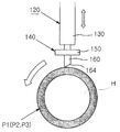
第1ノズル140は、図1および図2に示すように、第1塗料塗布手段120の塗料供給制御弁130に着脱可能に結合されて各ピストンP1、P2や双ピストン半製品P3をコーティングするためのコーティング装置を構成するが、第1塗料塗布手段120によって昇降しながら、回転支持手段110(図9参照)によって回転する各ピストンP1、P2や双ピストン半製品P3のヘッド部Hに塗料を噴射すると同時に、ヘッド部Hに噴射された剰余塗料液を一定の膜厚になるよう除去しながら拡布することによってヘッド部Hをコーティングする。
【0014】
第1ノズル140はノズルボディ150と、ノズルボディ150に一体に設置される塗料拡布手段160を備える。
【0015】
ノズルボディ150は塗料供給制御弁130に着脱可能に結合され、内部に塗料供給制御弁130と通ずる塗料噴射孔(図示せず)が形成されることによって塗料供給制御弁130から塗料を供給できるようになっている。即ち、ノズルボディ150にはこれを塗料供給制御弁130に固定するための多数のボルト穴(図示せず)が形成され、略中央部に塗料供給制御弁130と通ずる塗料噴射孔が形成される。また、塗料拡布手段160には、図2、図3および図8に示すように、ノズルボディ150の塗料噴射孔と通ずる少なくとも一つの塗料噴射孔162が形成される。したがって、塗料は、塗料供給制御弁130からノズルボディ150および塗料拡布手段160の塗料噴射孔162を通じて噴射されて回転するピストンP1、P2や双ピストン半製品P3のヘッド部H外周面に塗布される。
【0016】
本実施の形態によれば、塗料拡布手段160はノズルボディ150に一体に形成してもよく、ノズルボディ150とは別途に形成してノズルボディ150と一体に組立ててもよい。塗料拡布手段160は、図2、図11、図16、図20に示すように、被コーティング体、即ち各ピストンP1、P2や双ピストン半製品P3のヘッド部Hのうちコーティング部位の幅と同幅を有するか、やや大きい幅を有するのが好ましい。即ち、塗料拡布手段160が前述した大きさの幅を有することによって、塗料噴射孔162によってヘッド部H外周面に塗布される塗料液が図3に示すように塗料拡布手段160によって除去されながら図1に示すように一定の膜厚にコーティングされる。要するに、ノズルとブレードを各々別途に備え、これらを各々別途の手段によって駆動および制御する従来とは違って、ノズルボディ150に塗料拡布手段160が一体に設置された一つの第1ノズル140によってヘッド部Hをコーティングできるため、別途のブレードおよびこのブレードを駆動および制御する手段が要求されない。したがって、後述するコーティング装置の全体構造を単純化し得る利点がある。
【0017】
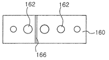
また、塗料拡布手段160に形成された塗料噴射孔162は、少なくとも一つ以上形成され、多様な変形例があり得る。即ち、ノズルボディ150の塗料噴射孔と通ずるように図4ないし図7のように塗料噴射孔162が塗料拡布手段160を垂直に貫通して形成されるのが好ましいが、この塗料噴射孔162が必ずしも塗料拡布手段160を貫通するように形成される必要はない。例えば、ここでは具体的に示してはいないが、各ピストンP1、P2や双ピストン半製品P3が図1および図3の矢印方向に回転する場合、塗料拡布手段160の前方、つまり図1および図3で右側に塗料噴射孔162が配置されると、本発明の所期の目的は達成される。
【0018】
さらに、塗料拡布手段160には多様な形状に塗料噴射孔162を形成することができ、また、多数の塗料噴射孔162を多様に配置、形成することができる。例えば、塗料噴射孔162を図4のように一つの長孔形態で形成することができる。また、図5に示すように多数の独立した小孔形態に塗料噴射孔162を形成することができるが、この場合、その各々の小孔は被コーティング体、例えば圧縮機ピストンの形状や構造によって図5のように一定の間隔に形成してもよく、図7に示すように、ある一側から他側に行くにつれて大きさが漸次大きくなるか、小さくなるように形成することもできる。また、塗料噴射孔162は図6のように長孔と小孔が組み合わせた形態で形成してもよく、図7のように相異なる大きさの小孔で形成することもできる。
【0019】
また、第1ノズル140の下面は、ヘッド部Hに噴射された剰余塗料液を除去しながら拡布するのを容易にするために、例えば、図3に示すように所定角度(θ)の傾斜面164で形成することができる。傾斜面164は各ピストンP1、P2や双ピストン半製品P3の回転方向側にある塗料拡布手段160の面を前面と称する場合、この前面から背面に傾くように形成するのが好ましいが、これに限定されなくても本発明の目的を達成することができる。例えば、傾斜面164が、前記方向と反対方向に形成される場合にもコーティングされる間に各ピストンP1、P2または双ピストン半製品P3は数多くの回転をするようになるので、結果的には所期の目的を達成することができる。即ち、塗料拡布手段160の傾斜面164先端の鋭い部分によって剰余塗料液を一定の膜厚になるよう除去しながら拡布することができる。また、このような傾斜面164がない場合にも同様に本発明の所期の目的を達成する上であまり支障はない。
【0020】
また、傾斜面164は鋭角範囲の傾斜角度を有するのが好ましい。好ましい傾斜面164の角度は5〜45°であり、最も好ましい傾斜角度は25°程度であるが、前述のように傾斜面164がない場合にも本発明の目的を十分に達成できるため、傾斜面164の傾斜角度は本発明において特に制限はない。
【0021】
一方、圧縮機ピストンP1、P2のヘッド部H外周面には、通常、オイルが流入するか、圧縮リングが結合される溝Gが形成されるが、この溝Gに対するコーティング膜厚を考慮せざるをえない。この点を考慮して、本発明では、図8に示すように、溝Gに対応する塗料拡布手段160の下面に、溝Gに塗布される塗料量を制御するための突起166が形成される。即ち、ヘッド部H外周面に対するコーティング膜厚は、塗料拡布手段160の下端とヘッド部H外周面との間隙、および溝Gと突起166との間隙で決定され、この間隙は、第1塗料塗布手段120を昇降させる昇降手段(図示せず)によって任意に調節することができる。
【0022】
<実施の形態2>
図9、図12ないし図15を参照して本発明の実施の形態2による塗膜形成用ノズルについて説明する。ここで、実施の形態2による塗膜形成用ノズルを便宜上第2ノズル240と称する。
【0023】
第2ノズル240は、上下移動およびスライディング可能に設置される第2塗料塗布手段220の塗料供給制御弁230に着脱可能に結合されて固定容量型斜板式圧縮機用ピストンP1をコーティングするためのコーティング装置を構成するが、第2塗料塗布手段220によってピストンP1の軸方向にスライディングしながら、ピストンP1のブリッジ部Bに塗料を噴射すると同時に、噴射された剰余塗料液を一定の膜厚になるよう除去しながら拡布させることによってブリッジ部Bをコーティングする。
【0024】
この第2ノズル240は、ノズルボディ250とノズルボディ250の両側に一体に設置される一対の塗料拡布手段260、260を備える。
【0025】
ノズルボディ250は塗料供給制御弁230に着脱可能に結合され、内部に塗料供給制御弁230と通ずる塗料噴射孔(図示せず)が形成されることによって塗料供給制御弁230から塗料を供給できるようになっている。また、各塗料拡布手段260にはノズルボディ250の塗料噴射孔と通ずる少なくとも一つの塗料噴射孔262が形成される。したがって、塗料は、塗料供給制御弁230からノズルボディ250および塗料拡布手段260の塗料噴射孔262を通じて噴射されて塗料拡布手段260のスライディングによってピストンP1のブリッジ部Bに塗布される。
【0026】
本実施の形態の第2ノズル240においても、図4ないし図7に示すように、塗料拡布手段260の塗料噴射孔262は一つの長孔形態で形成するか、多数の独立した小孔形態で形成することができ、且つ、これらが組み合わさられた形態で構成することもできる。このような塗料噴射孔262の形態および個数は、被コーティング体の固定容量型斜板式圧縮機用ピストンP1の形状にしたがって適切な変更が可能である。
【0027】
また、第2ノズル240はピストンP1のブリッジ部Bに沿って移動しながらブリッジ部Bをコーティングするようになるが、塗料の拡布を容易にするために各塗料拡布手段260の下端はブリッジ部Bの塗布面に好適な形態に形成されるのが好ましい。しかし、ヘッド部Hとは異なり、ブリッジ部Bには圧縮機斜板が結合されることから耐摩耗性は要求されるものの、液密性は要求されないという点と、フィニッシング工程またはグラインディング工程を通じてコーティング膜が一定の膜厚に形成されるように後加工され得るという点を考慮し、前述した塗料拡布手段260の下端の形態は特に限定しなくてもよい。
【0028】
例えば、ブリッジ部Bに対して図13のような傾いた直線やブリッジ部Bの塗布面形態とは異なる曲率を有する曲線形態を塗料拡布手段260の下端に適用してもよく、図14のような多角度形態、多曲率を有する曲線形態または直線と曲線が複合した形態の下端を有する塗料拡布手段260を採用してもよい。したがって、塗料拡布手段260の下端の形態がブリッジ部Bの塗布面形態と必ずしも一致する必要はない。
【0029】
即ち、理論的には、ブリッジ部Bの塗布面が一定の曲率を有するので、これと同じ曲率で塗料拡布手段260の下端を形成しないと一定の膜厚が得られないと考えられるが、実際には、塗布面に吐出された塗料が表面張力や引張力などの作用によって不揃いに集め、乾燥/焼成過程で流れが発生するなどの影響によって一定の膜厚が得られない。このため、塗布面と正確に一致する形態に塗料拡布手段260の下端を形成せずに、均一な膜厚が得られる他の形態が適用されるのである。例えば、ブリッジ部Bの外側部分で表面張力によって塗料が集めるのを防止するために、ブリッジ部Bの外側を図14のように塗料拡布手段260の下端両側で覆い、ブリッジ部Bの内側部分より外側部分の塗膜厚が相対的に厚くなるのを防止できる。
【0030】
また、第2ノズル240において、各塗料拡布手段260はブリッジ部Bのコーティング部位の幅と同幅またはそれよりやや大きい幅を有するのが好ましい。
【0031】
また、各塗料拡布手段260の下面は、塗料の拡布を容易にするために、図15に示すように、第2ノズル240の移動方向とは反対方向に所定角度に傾いた傾斜面264で形成することができる。また、第2ノズル240において傾斜面264の角度は実施の形態1の第1ノズル140と同様に鋭角の範囲にするのが好ましいが、必ずしもこれに限定されるわけではない。
【0032】
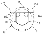
一方、前述のように構成された第2ノズル240は、後述するコーティング装置C1を構成してブリッジ部Bに下降した状態で第2塗料塗布手段220のスライディングによって塗料を塗布しながら一側にスライディングするようになるが、このスライディング動作時に流動が起こってはいけない。このために第2ノズル240は少なくとも一つのガイドポスト270を備える。このガイドポスト270は、その下端がブリッジ部Bに滑り接触するようにノズルボディ250に一体に形成されるが、ここでは2本のガイドポスト270、270が設置された例を示している。この場合、各ガイドポスト270は図15に示すように各塗料拡布手段260の前方(移動方向側)に配置されるのが好ましい。図示してはいないが、前述のように一対のガイドポスト270、270が設置されずに二つの塗料拡布手段260、260との間にブリッジ部Bに下端が接触するように一つのガイドポスト270がノズルボディ250に一体に設置されてもよい。前述のようにガイドポスト270の下端がブリッジ部Bに滑り接触することによって、第2ノズル240の移動が案内されるとともに、第2ノズル240の流動が防止される。
【0033】
また、ガイドポスト270は、その下端がブリッジ部Bに接触することによってブリッジ部Bに塗布される塗料の膜厚を決定する役割を兼ねるようになる。即ち、図15に示すように、ガイドポスト270は塗料拡布手段260より長く形成され、その下端が塗料拡布手段260の下端よりさらに下方に突出してブリッジ部Bに滑り接触するため、第2ノズル240の下降によってガイドポスト270の下端がブリッジ部Bに接触する際、塗料拡布手段260はブリッジ部Bに接触しなくなり、このときに形成されたブリッジ部Bと塗料拡布手段260の下端との間隙がブリッジ部Bに対するコーティング膜の厚さとなるのである。このようにガイドポスト270がブリッジ部Bに接触した状態で塗料拡布手段260が移動しながらブリッジ部Bに塗料が塗布されると同時に、剰余塗料液が除去されながら拡布されるため、ブリッジ部Bに一定の厚さのコーティング膜が形成される。
【0034】
<実施の形態3>
図16、図18、図19および図21には本発明の実施の形態3による塗膜形成用ノズルが示してあるが、ここで、実施の形態3による塗膜形成用ノズルを便宜上第3ノズル340と称する。
【0035】
本実施の形態の第3ノズル340は、例えば可変容量型斜板式圧縮機用ピストンP2の両側ウイング部W、Wをコーティングするに好適なものであって、各塗料拡布手段260の下端が被コーティング体の可変容量型斜板式圧縮機用ピストンP2の両側ウイング部W、Wの塗布面に好適な形態に形成されていることを除けば、実施の形態2の第2ノズル240と同一に構成することができる。したがって、第3ノズル340の構成要素のうち実施の形態2の第2ノズル240に対応する構成要素についは便宜上同一符号を付けるものとする。
【0036】
また、第3ノズル340においてガイドポスト270は、可変容量型斜板式圧縮機用ピストンP2において両側ウイング部W、Wがブリッジ部Bの両側に形成される点を考慮して、ノズルボディ250の二つの塗料拡布手段260、260との間に一つだけ形成されるのが好ましい。したがって、ガイドポスト270の下端は、可変容量型斜板式圧縮機用ピストンP2のヘッド部Hの後方に延長して両側ウイング部W、Wと連結するブリッジ部Bに滑り接触するようになる。
【0037】
次いで、前記実施の形態によるノズル140、240、340を利用して各ピストンP1、P2や双ピストン半製品P3をコーティングできるコーティング装置とコーティング方法について説明する。
【0038】
<実施の形態4>
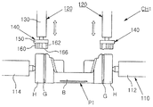
まず、図9ないし図15を参照して第1ノズル140および第2ノズル240を利用して固定容量型斜板式圧縮機用ピストンP1をコーティングする圧縮機ピストンコーティング装置C1について説明する。
【0039】
図9に示すように、本実施の形態において、コーティング装置C1は、ヘッド部コーティングユニットCH1とブリッジ部コーティングユニットCBを備える。勿論、このコーティング装置C1にはユニットCH1、CBの他にもピストンP1をヘッド部コーティングユニットCH1にローディングさせ、ヘッド部Hコーティングの完了したピストンP1をアンローディングしてブリッジ部コーティングユニットCBにローディングさせ、ブリッジ部Bコーティングの完了したピストンP1をアンローディングさせる多数のユニットがさらに具備されるが、それらのユニットは一般的に適用され得るので、便宜上、ここではその具体的な図示および説明は省略した。
【0040】
本発明によれば、ヘッド部コーティングユニットCH1は、ピストンP1の両側を回転可能に支持する回転支持手段110と、回転支持手段110の上部側に上下移動可能に設置され、回転支持手段110によって回転するピストンP1の両側ヘッド部H、H外周面に近接して各ヘッド部H外周面に塗料を塗布すると同時に、塗布された剰余塗料液を一定の膜厚に拡布させる一対の第1ノズル140、140を有する一対の第1塗料塗布手段120、120とを含めてなる。
【0041】
回転支持手段110は、ピストンP1の両端部側面の回転中心を支持する一対の支持部材112、114と、支持部材112、114のうち少なくとも一側の支持部材を回転させてピストンP1を回転させる回転手段(図示せず)を備える。このような回転支持手段110は、通常の構成からなり得るので、ここではその具体的な説明を省略する。
【0042】
第1塗料塗布手段120は、ピストンP1のヘッド部H外周面をコーティング処理できるようになったものであって、図10に示すように、昇降手段(図示せず)によって回転支持手段110の上部側に上下移動可能に設置できる。第1塗料塗布手段120は、塗料貯蔵手段から供給される塗料量を制御する塗料供給制御弁130と、塗料供給制御弁130に着脱可能に付着された第1ノズル140を有する。したがって、回転支持手段110に支持されて回転するピストンP1の両側ヘッド部H、H外周面に第1ノズル140の塗料拡布手段160が近接するように下降した状態で塗料拡布手段160の塗料噴射孔162を通じてヘッド部H外周面に塗料が塗布されると同時に、塗布された塗料が塗料拡布手段160の傾斜面164によって剰余塗料液が一定の膜厚になるよう除去されながら拡布されるので、両側ヘッド部H、Hに一定の厚さのコーティング膜を形成できる。また、溝Gに対するコーティング膜厚は、塗料拡布手段160の下面に形成される突起166によって溝Gに塗布される塗料量によって制御される。
【0043】
一方、コーティング装置C1のブリッジ部コーティングユニットCBは、ヘッド部コーティングユニットCH1によって両側ヘッド部H、Hのコーティングが完了したピストンP1のブリッジ部Bをコーティングするためのものであって、回転支持手段110に隣接して設置されてピストンP1の両側を支持する固定手段210と、固定手段210の上部側に上下移動およびスライディング可能に設置され、固定手段210に固定されたピストンP1のブリッジ部Bに近接してブリッジ部Bに塗料を塗布すると同時に、スライディングしながら塗布された剰余塗料液を一定の膜厚になるよう除去して拡散させる第2ノズル240を有する第2塗料塗布手段220とを備えてなる。
【0044】
固定手段210は、回転支持手段110とは異なり、ピストンP1の両端部側面の中心を固定する一対の固定部材212、214から構成されるが、この固定手段210の構造は通常の構造であるため、ここではその詳細な説明は省略する。また、ここで、回転支持手段110から固定手段210へのピストンP1の移動は別途の移送手段(図示せず)によって行われるので、その具体的な図示および説明は省略する。
【0045】
第2塗料塗布手段220は、ピストンP1のブリッジ部Bをコーティング処理できるものであって、図示しなかった昇降および移送手段によって固定手段210の上部側に上下移動およびスライディング可能に設置される。この第2塗料塗布手段220は、塗料貯蔵手段(図示せず)から供給される塗料量を制御する塗料供給制御弁230と、塗料供給制御弁230に着脱可能に設置される第2ノズル240を備える。したがって、第2塗料塗布手段220が下降してガイドポスト270が固定手段210に支持されたピストンP1のブリッジ部Bに接触すると、第2ノズル240の塗料拡布手段260がブリッジ部Bに所定の間隙をおいて近接し、この状態で塗料拡布手段260の塗料噴射孔262を通じてブリッジ部Bに塗料が塗布されると同時に、第2塗料塗布手段220のスライディングに沿って塗料拡布手段260がピストンP1の軸方向に移動する。この塗料拡布手段260の移動に沿って塗料拡布手段260の傾斜面264によってブリッジ部Bに塗布された剰余塗料液が一定の膜厚になるよう除去されながら拡布されるため、ブリッジ部Bに一定の厚さのコーティング膜を形成することができる。
【0046】
前述のように構成されたコーティング装置C1によってピストンP1の両側ヘッド部H、Hおよびブリッジ部Bを一連の連続した工程でコーティングする方法を以下に総合的に説明する。
【0047】
まず、回転支持手段110にピストンP1の両側を回転可能に支持させる。そして、ピストンP1の両側ヘッド部H、Hに各第1ノズル140の塗料拡布手段160が所定の間隙をおいて近接するように第1塗料塗布手段120を下降させる。この状態でピストンP1を回転させるとともに各第1塗料塗布手段120の第1ノズル140を通じて塗料液を噴射し、各塗料拡布手段160の剰余塗料液拡布によって両側ヘッド部H、Hの外周面に一定の膜厚に塗料液を同時にコーティングする。
【0048】
ヘッド部Hに対するコーティング過程において、回転支持手段110によって回転するピストンP1の回転速度は一定のものではなく、段階ごとに異なる。即ち、最初に第1ノズル140を通じてピストンP1のヘッド部Hに塗料液を噴射するときからピストンP1の1回転までにはピストンP1が相対的に低速に回転し、ピストンP1のヘッド部Hに塗料液が付着してからはピストンP1が相対的に高速に回転する。このように後で高速に回転すると、塗料液が安定的にヘッド部Hに拡布されるだけでなく、後述するように第1塗料塗布手段120の上昇時に塗布された塗料液が引き上げられることが防止される。また、ピストンP1の最初1回転の間にもその前半部回転速度および後半部回転速度が異なる。これは、塗料供給制御弁130で必然的に発生する塗料液吐出前半部と後半部の塗料液吐出量の差を回転速度で制御するためであり、 前半部と後半部のうちどちらの回転速度を相対的に高く設定するかは、バルブ種類およびその他の適用要因によって決定される。
【0049】
また、ヘッド部Hのコーティングに適用される塗料液は、後述するブリッジ部Bのコーティングに適用される塗料液の粘度と異なる粘度、好ましくは、ブリッジ部Bのコーティングに適用される塗料液の粘度より高い粘度を有する。例えばヘッド部Hのコーティングに適用される塗料液は略10,000〜30,000cpの粘度を有するのが好ましい。このようにヘッド部Hについて高粘度のコーティング塗料液を適用する理由は、乾燥工程中にコーティング体を回転させることなく乾燥工程が行えるようにするためであって、低粘度の塗料液が適用される場合には、乾燥工程中コーティング体を回転させないと塗料液が流下する恐れがあるからである。また、高粘度の塗料液を適用する場合に限って、乾燥/焼成後の所望する塗膜厚を得るためのウェット状態における塗布厚さおよび量が小さくなり、塗料液が流れる傾向を最小にすることができる。
【0050】
このように両側ヘッド部H、Hに対するコーティングが完了すると、第1塗料塗布手段120を上昇させる。そして、ヘッド部HがコーティングされたピストンP1を移送手段によって固定手段210に移送し固定手段210にピストンP1の両側を支持させる。次いで、固定手段210に支持されたピストンP1のブリッジ部Bにガイドポスト270が接触することによって第2ノズル240の各塗料拡布手段260が所定の間隙をおいてブリッジ部Bに近接するように第2塗料塗布手段220を下降させる。この状態で第2塗料塗布手段220をピストンP1の軸方向にスライディングさせるとともに、第2ノズル240を通じて塗料を噴射し、塗料拡布手段260の剰余塗料液拡布によってブリッジ部Bに一定の膜厚に塗料液をコーティングする。
【0051】
ブリッジ部Bに対するコーティング過程においては、第2塗料塗布手段220のスライディング移送速度が一定でなく、段階ごとに異なる。即ち、塗料液吐出量を考慮して、第2ノズル240を通じてピストンP1のブリッジ部Bに塗料液を噴射する第2塗料塗布手段220の初期スライディング移送速度は速く、中間移送速度は遅く、最終移送速度は再び速くなる。最終移送速度を速くする理由も、同様に第2塗料塗布手段220を上昇させるとき塗布された塗料液が引き上げられることを防止するためである。
【0052】
また、ブリッジ部Bのコーティングに適用される塗料液はヘッド部Hにコーティングされる塗料液の粘度より低い粘度、例えば、略10,000cp以下の粘度を有するのが好ましい。ヘッド部Hと同粘度の塗料液をブリッジ部Bに適用するのが塗料液の管理や共用化側面において有利であるが、ブリッジ部Bは特別な後加工がない限り厚さなどの仕様を満足させるに困難があり得る。したがって、ブリッジ部Bに低い粘度の塗料液を適用するのは、固形分を低減させて乾燥/収縮後の管理を容易にするためである。
【0053】
そして、ブリッジ部Bに対するコーティングが終わると、第2塗料塗布手段220を再び上昇させ、ブリッジ部Bのコーティングが完了したピストンP1をアンローディング手段(図示せず)によってアンローディングする。
【0054】
コーティング装置C1によるコーティング過程によれば、ヘッド部コーティングユニットCH1とブリッジ部コーティングユニットCBで同時に各々異なるコーティング工程が行われるので、ピストンP1に対するコーティング作業が一連の連続した工程で行われる。つまり、従来はブリッジ部Bに対するディスペンサコーティングが不可能であって、ピストンP1のヘッド部Hに対するディスペンサ工法によるコーティングを行った後、ヘッド部Hコーティングが完了されたピストンP1を他の場所または他の装置に移動し、例えばスプレー工法によってブリッジ部Bのコーティングを行ったが、本発明では一つのコーティング装置C1でヘッド部Hコーティングとブリッジ部Bコーティングが連続的に行われるので、生産性を著しく高くできる利点がある。また、従来はノズルとブレードが別途に構成されて各々別途の手段によって駆動および制御されたが、本発明ではノズルに塗料拡布手段が一体に備えられているので、ノズルと別途に形成されたブレードおよびこのブレードを駆動および制御する手段が要求されない。したがって、コーティング装置の構造的な単純化および小型化を具現できることは勿論、管理ポイントが減少し、装置のメンテナンスが容易な利点を有する。
【0055】
<実施の形態5>
次いで、図16ないし図19を参照して第1ノズル140および第3ノズル340を利用して可変容量型斜板式圧縮機用ピストンP2をコーティングするようになった圧縮機ピストンコーティング装置C2について説明する。
本実施の形態において、コーティング装置C2は、ヘッド部コーティングユニットCH2とウイング部コーティングユニットCWを備える。勿論、このコーティング装置C2には、前述したコーティング装置C1におけると同様に、ユニットCH2、CW以外にも、ピストンP2をヘッド部コーティングユニットCH2にローディングさせ、ヘッド部Hコーティングが完了されたピストンP2をアンローディングしウイング部コーティングユニットCWにローディングさせ、両側ウイング部W、Wのコーティングが完了したピストンP2をアンローディングさせる多くのユニットをさらに備える。
【0056】
本例のコーティング装置C2において、ヘッド部コーティングユニットCH2は、ピストンP2の両側を回転可能に支持する回転支持手段110と、回転支持手段110の上部に上下移動可能に設置され、回転支持手段110によって回転するピストンP2のヘッド部Hに近接してヘッド部Hに塗料を塗布すると同時に、塗布された剰余塗料液を一定の膜厚に拡布させる第1ノズル140を有する第1塗料塗布手段120と、を含めてなる。即ち、可変容量型斜板式圧縮機用ピストンP2が一つのヘッド部Hを備えることからヘッド部コーティングユニットCH2も一つの第1塗料塗布手段120だけを備えることを除けば、コーティング装置C1に採用されたヘッド部コーティングユニットCH1と同様な構成となっている。したがって、回転支持手段110および第1塗料塗布手段120に対する説明は既になされているので、ここでは具体的な説明は省略する。
【0057】
また、本実施の形態のコーティング装置C2において、ウイング部コーティングユニットCWは、ヘッド部コーティングユニットCH2によってヘッド部Hのコーティングが完了したピストンP2の両側ウイング部W、Wをコーティングするためのものであって、回転支持手段110に隣接して設置されてピストンP2の両側を支持する固定手段210と、固定手段210の上部側に上下移動およびスライディング可能に設置され、固定手段210に固定されたピストンP2の両側ウイング部W、Wに近接して両側ウイング部W、Wに塗料を塗布すると同時に、スライディングしながら塗布された剰余塗料液を一定の膜厚になるよう除去しながら拡散させる第3ノズル340を備える第2塗料塗布手段220と、を含めてなる。第3ノズル340は、第2ノズル240において両側塗料拡布手段260、260の下端がウイング部Wの塗布面形態に好適に形成されるとともに、ガイドポスト270がピストンP2のブリッジ部Bに滑り接触するように一対の塗料拡布手段260、260との間に設置されている点を除けば、前述した第2ノズル240と同一に構成され、したがって、第3ノズル340を備える第2塗料塗布手段220と固定手段210に対する詳細な説明は省略する。
【0058】
このように構成されたコーティング装置C2によってピストンP2のヘッド部Hおよび両側ウイング部W、Wを一連の連続した工程でコーティングする方法を以下に総合的に説明する。
【0059】
まず、回転支持手段110にピストンP2の両側を回転可能に支持させる。そして、ピストンP2のヘッド部Hに第1ノズル140の塗料拡布手段160が所定の間隙をおいて近接するように第1塗料塗布手段120を下降させる。この状態でピストンP2を回転させるとともに第1塗料塗布手段120の第1ノズル140を通じて塗料液を噴射し、塗料拡布手段160の剰余塗料液拡布によってヘッド部Hの外周面に一定の膜厚に塗料液を同時にコーティングする。
【0060】
本実施の形態においても、ピストンP2の回転速度を、前記実施の形態4のピストンP1の回転速度と同様に変化させてヘッド部Hに対するコーティングを行うのが好ましく、塗料液も同一の粘度のものが適用される。
【0061】
ヘッド部Hに対するコーティングが完了すると、第1塗料塗布手段120を上昇させる。そして、ヘッド部HがコーティングされたピストンP2を移送手段によって固定手段210に移送し、固定手段210にピストンP2の両側を支持させる。次いで、固定手段210に支持されたピストンP2のブリッジ部Bにガイドポスト270が接触することによって第3ノズル340の各塗料拡布手段260が所定の間隙をおいてウイング部Wに近接するように第2塗料塗布手段220を下降させる。この状態で第2塗料塗布手段220をピストンP2の軸方向にスライディングさせるとともに第3ノズル340を通じて塗料を噴射し、各塗料拡布手段260の剰余塗料液拡布によって両側ウイング部W、Wに一定の膜厚に塗料液をコーティングする。
【0062】
ウイング部Wに対するコーティング過程において、第2塗料塗布手段220のスライディング移送速度を、前記実施の形態4でのブリッジ部Bに対するコーティング時の第1塗料塗布手段120の移送速度のパターンと同一のパターンで適用するのが好ましく、このウイング部Wに対するコーティング塗料液は、ヘッド部Hに対する塗料液と同一の粘度を有するものかもしくは低い粘度有するものとして適用するのが好ましい。
【0063】
そして、ウイング部Wに対するコーティングが完了すると、第2塗料塗布手段220を再び上昇させた後、両側ウイング部W、Wのコーティングが完了したピストンP2をアンローディング手段によってアンローディングする。
【0064】
前述したようなコーティング装置C2によるコーティング過程において、ヘッド部コーティングユニットCH2とウイング部コーティングユニットCWで同時に各々異なるコーティング工程が行われるので、可変容量型斜板式圧縮機用ピストンP2に対するコーティング作業が一連の連続した工程で行うことができる。
【0065】
<実施の形態6>
また、本発明によれば、図20および図21に示すように、可変容量型斜板式圧縮機用ピストンP2の製造工程中、双ピストン半製品P3を切断して2個のピストンP2に製造完了する前に双ピストン半製品P3をコーティングできるように構成されたコーティング装置C3が提供される。
【0066】
本実施の形態によれば、コーティング装置C3は、双ピストン半製品P3において両側にヘッド部Hが各々配置され、中央にウイング部W、W同士が相接した状態に形成されることから、第1塗料塗布手段120によって一側のヘッド部Hをコーティングできるとともに、他側のヘッド部Hは第1塗料塗布手段120と同様に構成された第3塗料塗布手段320によってコーティングされるようになっており、また、第2塗料塗布手段220によって全てのウイング部Wをコーティングできるようになっていることを除けば、前述したコーティング装置C2と同一である。したがって、コーティング装置C3に対する詳細な説明は省略する。
【0067】
このように構成されたコーティング装置C3によって双ピストン半製品P3の両側ヘッド部H、Hおよびウイング部Wを一連の連続した工程でコーティングする方法を以下に総合的に説明する。
【0068】
まず、回転支持手段110に双ピストン半製品P3の両側、即ち両側ヘッド部H、Hのヘッド面を回転可能に支持させる。そして、回転支持手段110に支持された双ピストン半製品P3の両側ヘッド部H、Hに各第1ノズル140の塗料拡布手段160が所定の間隙をおいて近接するように第1塗料塗布手段120および第3塗料塗布手段320を下降させる。この状態で双ピストン半製品P3を回転させるとともに第1塗料塗布手段120の第1ノズル140および第3塗料塗布手段320の第1ノズル140を通じて塗料液を噴射し、各塗料拡布手段160の剰余塗料液拡布によって両側ヘッド部H、Hの外周面に一定の膜厚に塗料液を同時にコーティングする。ヘッド部Hに対するコーティングが完了すると、第1塗料塗布手段120および第3塗料塗布手段320を上昇させる。そして、両側ヘッド部H、Hがコーティングされた双ピストン半製品P3を移送手段によって固定手段210に移送し、固定手段210に双ピストン半製品P3の両側を支持させる。次いで、固定手段210に支持された双ピストン半製品P3のブリッジ部B3にガイドポスト270が接触することによって第3ノズル340の各塗料拡布手段260が所定の間隙をおいてウイング部Wに近接するように第2塗料塗布手段220を下降させる。この状態で第2塗料塗布手段220を双ピストン半製品P3の軸方向にスライディングさせるとともに第3ノズル340を通じて塗料を噴射し、各塗料拡布手段260の剰余塗料液拡布によってウイング部Wに一定の膜厚に塗料液を同時にコーティングする。そして、第2塗料塗布手段220を再び上昇させた後、両側ウイング部W、Wのコーティングが完了した双ピストン半製品P3をアンローディング手段によってアンローディングする。この双ピストン半製品P3のうちウイング部Wを相接させた中央部分を切断すると、二つのピストンP2、P2が得られる。
【0069】
前記一双ピストン半製品P3のヘッド部Hおよびウイング部Wに対するコーティング過程において、コーティング塗料液と、双ピストン半製品P3の回転速度および第2塗料塗布手段220のスライディング移送速度は、前記実施の形態5におけると同様に適用することができるので、その詳細な説明は省略する。
【0070】
【発明の効果】
本発明によれば、ピストンのコーティングに際してヘッド部コーティングとブリッジ部またはウイング部のコーティングを一つの装置で一連の連続した工程で実施することができるため、生産性および品質向上を図ることができる。また、エアスプレー工法でないディスペンサ工法が適用されるため、塗料飛散による過大な塗料消耗および周辺機器の汚染を根本的に防止することができる。
【図面の簡単な説明】
【図1】 本発明の実施の形態1による塗膜形成用ノズルが適用された塗料塗布手段によって被コーティング体がコーティングされる状態を示す側面図である。
【図2】 図1の正面図である。
【図3】 図1の部分拡大図である。
【図4ないし7】 各々本発明の実施の形態1によるノズルに形成される塗料噴射孔の例を示す底面図である。
【図8】 本発明の実施の形態1によるノズルを構成する塗料拡布手段の下端に被コーティング体に形成された溝に対応する突起が形成されて被コーティング体の溝に対するコーティング膜厚が制御される状態を示す一部正面図である。
【図9】 本発明の実施の形態1による一対のノズルと、実施の形態2によるノズルが適用された圧縮機ピストンコーティング装置によって固定容量型斜板式圧縮機用ピストンが一連の連続工程でコーティングされる状態を示す斜視図である。
【図10】 図9において固定容量型斜板式圧縮機用ピストンの両側ヘッド部がコーティングされる状態を示す正面図である。
【図11】 図9の一部拡大図である。
【図12】 図9において本発明の実施の形態2によるノズルによって固定容量型斜板式圧縮機用ピストンのブリッジ部がコーティングされる状態を説明するための図である。
【図13】 図12の部分拡大図である。
【図14】 図12の部分拡大図であって、他の形態の塗料拡布手段が採用された例を示す図である。
【図15】 図12の部分左側面図である。
【図16】 本発明の実施の形態1によるノズルと実施の形態3によるノズルが適用された圧縮機ピストンコーティング装置によって可変容量型斜板式圧縮機用ピストンが一連の連続工程でコーティングされる状態を示す正面図である。
【図17】 図16の部分拡大図である。
【図18】 本発明の実施の形態3によるノズルによって可変容量型斜板式圧縮機用ピストンの両側ウイング部がコーティングされる状態を説明するための図である。
【図19】 図18の部分左側面図である。
【図20および図21】 各々本発明の実施の形態1による一対のノズルおよび本発明の実施の形態3によるノズルが適用された圧縮機ピストンコーティング装置によって、可変容量型斜板式圧縮機用ピストンの製造過程で製造される双ピストン半製品が一連の連続工程でコーティングされることを説明するための図である。
【符号の説明】
110:回転支持手段
112、114:支持部材
120、220:塗料塗布手段
130:塗料供給制御弁
140:第1ノズル
150、250:ノズルボディ
160、260:塗料拡布手段
162、262:塗料噴射孔
164、264:傾斜面
166:突起
210:固定手段
212:固定部材
240:第2ノズル
270:ガイドポスト
320:第3塗料塗布手段
340:第3ノズル
B:ブリッジ部
G:溝
H:ヘッド部
P1:固定容量型斜板式圧縮機用ピストン
P2:可変容量型斜板式圧縮機用ピストン
P3:双ピストン半製品
W:ウイング部[0001]
BACKGROUND OF THE INVENTION
The present inventionThe compressor piston coating method, more specifically,Forms a coating on the surface of parts used in products that require wear resistance and liquid tightness, for example, compressor pistonsIn doingThe coating material to be applied is spread to a certain film thickness by the dispenser method, and the piston for the compressor is made in a series of continuous processes.InCoating film forming nozzle that can be coatedWithCompressor piston coating equipmentCompressor piston coating by coatingRegarding the method.
[0002]
[Prior art]
Parts used in products that require wear resistance and liquid tightness, such as pistons used in compressors, form a coating film with a predetermined thickness on the surface to improve wear resistance and liquid tightness. Such coating techniques are already used in various fields. As is well known, an important point in such coating techniques is that the applied film must maintain a constant thickness. In particular, for example, a Teflon (registered trademark) coating film is coated on the outer peripheral surface of the head portion of the compressor piston. In the coating of the compressor piston, the thickness and precision of the coating film are greatly affected by the performance of the compressor. It is an extremely important management point because it has an impact.
[0003]
Conventionally, coating methods such as powder coating, spraying and electrostatic painting have been employed as coating methods for increasing the wear resistance and liquid tightness of compressor pistons. However, these coating methods are problematic because of variations in coating film thickness. In particular, the spray coating method has a problem in that the coating process is complicated and the paint scatters during the spraying and is coated to other parts that do not need to be coated. is there. In addition, the spray coating method has a problem that the periphery is greatly contaminated by the paint scattered during coating.
[0004]
In order to solve such problems of the conventional spray coating method, Japanese Patent Laid-Open No. 8-173893 and International Patent Application No. PCT / JP00 / 00096 support a cylindrical coated body in a rotatable manner. A rotation support device, and a coating material injection device that has a nozzle for applying paint on the outer peripheral surface of the object to be coated that is rotated by the rotation support device, and is installed on the upper portion of the rotation support device so as to be vertically movable; Disclosed is a coating apparatus including a blade for removing a surplus coating liquid applied to an outer peripheral surface of a coated body by a paint spraying device and diffusing the paint while maintaining a constant film thickness. Yes.
[0005]
However, in the above-described conventional coating apparatus, a separate blade for removing excess paint liquid applied to the outer peripheral surface of the cylindrical coated body is separated from the nozzle at a position adjacent to the rotating coated body. Since it must be installed on the body, the overall structure of the coating apparatus is relatively complicated, and the driving and control of the paint diffusing apparatus is also complicated, resulting in an increase in maintenance and management points of the coating apparatus. Become.
[0006]
In addition, for example, coating can be applied to the outer peripheral surface of the head portion of the compressor piston by a conventional coating apparatus, but the bridge portion of the piston for the fixed displacement type swash plate compressor and the wing portions on both sides of the piston for the variable displacement swash plate compressor Cannot be coated. For this reason, it is necessary to transfer the coated piston on the outer peripheral surface of the head part to another place or another device and coat the bridge part or both wing parts by a spray method. This dualization of the coating method further increases the complexity of the coating work, and the typical problem of the spray method, that is, the problem of contamination of peripheral equipment due to increased paint consumption and paint scattering, remains. .
[0007]
[Problems to be solved by the invention]
The present invention has been made in view of the above problems, and at the same time as applying the paint, the paint applied by the paint spreading means integrated with the nozzle can be spread to a certain film thickness to form a coating film. Accordingly, an object of the present invention is to prevent the blade that has been used separately from the conventional nozzle for removing the surplus paint liquid from being separately formed.
[0008]
[Means for Solving the Problems]
The present inventionTwo columnar head portions on the same axis, and a bridge portion formed by extending a part of a cross section including the outer periphery of the head portion in a direction parallel to the head axis between the head portions; , Integrally formedBoth sides of piston for fixed capacity swash plate compressorHeadA rotation support means for rotatably supporting the piston, and a piston which is installed on the upper side of the rotation support means so as to be vertically movable and is rotated by the rotation support means.AboveClose to the outer peripheral surface of both headsAboveA first coating material application means comprising a pair of first nozzles for applying a coating material to the outer peripheral surface of each head portion and simultaneously removing the applied excess coating solution so as to have a constant film thickness; Installed adjacent to both sides of the pistonHeadA fixing means for supporting the piston, and installed on the upper side of the fixing means so as to be vertically movable and sliding, and the piston supported by the fixing means.AboveClose to the bridgeAboveAt the same time as applying the paint to the bridge part, remove the surplus paint liquid applied while sliding so that the film thickness is constant.ExpansionAnd a second coating material application means having a second nozzle to cause the piston of the fixed capacity type swash plate compressor piston toAboveBoth sides head andAboveA compressor piston coating method for coating a bridge portion in a series of continuous processes, wherein the rotating support meansAboveBoth sides of the pistonHeadAnd rotatably supporting the piston,AboveOn both sides headAboveOf each first nozzleAboveMake the paint spreading means closeAboveA step of lowering the first paint applying means, and rotating the piston;AboveOf each first paint application meansAboveSpray the paint liquid through the first nozzle,AboveBy surplus paint liquid spreading of paint spreading meansBoth sidesCoating the head with a coating liquid with a certain film thicknessMakeRaising the first paint application means; andboth sidesThe piston with the coated headAboveBy means of transfer from the rotation support meansAboveTransport to fixing meansAboveFor fixing meansSaidBoth sides of the pistonHeadSupportMakeSupported by the fixing meansAbovePistonAboveOn the bridgeAboveThe second nozzleAboveMake each paint spreading means closeAboveA step of lowering the second paint application means, and the second paint application meansAboveSliding in the axial direction of the pistonAboveSpray the paint liquid through the second nozzle,AboveBy surplus paint liquid spreading of paint spreading meansAboveCoating the bridge with a coating film with a certain thicknessMakeAnd the second coating material applying means includes the second nozzle.AboveThe piston further protrudes downward from the paint spreading means.AboveA guide post slidingly contacting the bridge portion, wherein the lower end of the guide post is lowered when the second coating material applying means is lowered;AboveBy touching the bridgeAboveBy forming a predetermined gap between the lower end of the paint spreading means and the bridge portion of the pistonAboveThe coating thickness for the bridge is determined,The viscosity of the coating liquid applied to the head part is higher than the viscosity of the coating liquid applied to the bridge part.It is characterized by that.
[0009]
In addition, the present invention provides a cylindrical head portion, a bridge portion in which a part of a cross section including an outer periphery of the head portion extends in a direction parallel to the axis from one axial end of the head portion, and the bridge portion At the tip ofFrom the bridge sectionIn a direction parallel to the outer peripheral direction of the head portionOn both sidesOf the piston for a variable capacity swash plate compressor integrally formed with the extending wingThe head and bridgeRotation support means for supporting the rotation, and an upper side of the rotation support means, which is installed so as to be movable up and down, and close to the outer periphery of the head part of the piston rotated by the rotation support means. At the same time as the coating material is applied, a first coating material coating means provided with a first nozzle that removes and spreads the applied surplus coating liquid so as to have a constant film thickness; and a piston installed adjacent to the rotation support means.Head and bridgeA fixing means for supporting the upper and lower sides of the fixing means so as to be vertically movable and sliding, and at the same time as applying the paint to the wing portion in the vicinity of the wing portion of the piston supported by the fixing means, The variable capacity swash plate compressor is provided with a coating apparatus comprising: a second paint application unit having a third nozzle that removes and spreads the surplus coating liquid applied while sliding so as to have a constant film thickness. A compressor piston coating method for coating the head portion and the wing portion of a piston for a piston in a series of continuous steps, wherein the rotation support means is coated with the piston.Head and bridgeAnd a step of lowering the first coating material application means so that the coating material spreading means of the first nozzle comes close to the head portion of the piston, and rotating the piston and the first. Injecting paint liquid through the first nozzle of the paint application means, coating the head portion with the paint liquid to a certain film thickness by spreading the surplus paint liquid of the paint spread means, and raising the first paint application means And transferring the piston coated with the head part from the rotation support means to the fixing means by a transfer means, and the piston is moved to the fixing means.Head and bridgeA step of lowering the second coating material application means so that the coating material spreading means of the third nozzle comes close to the wing portion of the piston supported by the fixing means; Sliding the coating material application means in the axial direction of the piston, spraying the coating liquid through the third nozzle, and coating the coating liquid with a certain film thickness on the wing portion by spreading the remaining coating liquid through the coating material spreading means; The second coating material application means has a guide post that further protrudes downward from the coating material spreading means of the third nozzle and slides into contact with the bridge portion of the piston. When the lower end of the guide post comes into contact with the bridge portion in the lowering step, the lower end of the paint spreading means and the piston of the piston are A predetermined gap is formed between the wing part and the coating film thickness for the wing part is determined, and the viscosity of the coating liquid applied to the wing part is lower than the viscosity of the coating liquid applied to the head part. It is characterized by being.
[0010]
In addition, the present invention provides a cylindrical head portion, a bridge portion in which a part of a cross section including an outer periphery of the head portion extends in a direction parallel to the axis from one axial end of the head portion, and the bridge portion At the tip ofFrom the bridge sectionIn a direction parallel to the outer peripheral direction of the head portionOn both sidesDuring the manufacturing process of the variable displacement swash plate compressor piston that is integrally formed with the extending wing portion, the wing portions before cutting into two variable displacement swash plate compressor pistonsTouchedIn a symmetrical bi-piston semi-finished product, a rotary support means for rotatably supporting both head portions of the bi-piston semi-finished product, and an upper side of the rotary support means are installed so as to be movable up and down, and rotated by the rotary support means. The coating material is applied to the outer peripheral surface of each head portion in the vicinity of the outer peripheral surfaces of the head portions on both sides of the double piston semi-finished product, and at the same time, the applied surplus coating liquid is removed so as to have a constant film thickness and spread. A first paint application means and a third paint application means each comprising a nozzle; a fixing means installed adjacent to the rotation support means to support both side head portions of the bi-piston semi-finished product; and an upper portion of the fixing means Proximity to the wing part, which is installed on the side so as to be movable up and down and can be slid, and is arranged in an intertwined state among the double piston semi-finished products supported by the fixing means A coating apparatus comprising: a second paint application unit including a third nozzle that applies a paint to the wing portion and simultaneously removes and spreads a surplus paint liquid applied while sliding so as to have a constant film thickness. A compressor piston coating method in which both side head portions and the wing portion of the double piston semi-finished product are coated in a series of continuous steps, and the both side head portions of the double piston semi-finished product can be rotated on the rotation support means. And applying the first paint so that the first paint application means and the paint spreading means of the first nozzles of the third paint application means are close to the heads on both sides of the double-piston semi-finished product. Lowering means and the third paint application means, rotating the double-piston semi-finished product and the first paint application hand And spraying a coating liquid through each of the first nozzles of the third coating material applying means, and coating the head portion with the coating liquid to a certain film thickness by spreading the remaining coating liquid of the coating material spreading means; Raising the paint application means and the third paint application means, and transferring the bi-piston semi-finished product coated with the head portion from the rotation support means to the fixing means by the transfer means, to the fixing means; A step of supporting both side heads of the piston semi-finished product, and a center portion of the bi-piston semi-finished product supported by the fixing means, and the respective paint spreading means of the third nozzle are close to the uncut wing portion A step of lowering the second paint application means, and sliding the second paint application means in the axial direction of the bi-piston semi-product. Spraying a coating liquid through the third nozzle and coating the wing portion with a coating film by surplus coating liquid spreading of the coating spreading means, and the second coating application means comprises: A guide post that protrudes further downward from the paint spreading means of the third nozzle and slides into contact with the bridge portion of the semi-piston semi-finished product. When the lower end contacts the bridge portion of the double-piston semi-finished product, a predetermined gap is formed between the lower end of the paint spreading means and the wing portion of the bi-piston semi-finished product. The viscosity of the coating liquid applied to the wing part is lower than the viscosity of the coating liquid applied to the head part. To.
[0011]
DETAILED DESCRIPTION OF THE INVENTION
Hereinafter, the present invention will be described in detail based on embodiments and the accompanying drawings.
In the following detailed description, reference numeral P1 is a cylindrical coated body and represents a piston for a fixed displacement swash plate compressor, P2 represents a piston for a variable displacement swash plate compressor, and P3 is variable. Represents a double-piston semi-finished product manufactured during the manufacturing process of a piston for a capacity type swash plate compressor. Reference numeral H denotes the head portion of each piston P1, P2 or twin piston semi-finished product P3, G denotes an annular groove formed on the outer peripheral surface of the head portion H, and B denotes each piston P1, P2 or twin piston half product. W represents the bridge portion of the product P3, and W represents the wing portion of the piston P2 for the variable displacement swash plate compressor or the half piston P3.
[0012]
<Embodiment 1>
A coating film forming nozzle according to Embodiment 1 of the present invention will be described with reference to FIGS. Here, the coating film forming nozzle according to Embodiment 1 is referred to as a
[0013]
As shown in FIGS. 1 and 2, the
[0014]
The
[0015]
The
[0016]
According to the present embodiment, the paint spreading means 160 may be formed integrally with the
[0017]
Further, at least one
[0018]
Further, the paint spreading means 160 can be formed with various paint injection holes 162 in various shapes, and a large number of paint injection holes 162 can be arranged and formed in various ways. For example, the coating
[0019]
Further, the lower surface of the
[0020]
The
[0021]
On the other hand, on the outer peripheral surfaces of the head portions H of the compressor pistons P1 and P2, a groove G into which oil flows or a compression ring is coupled is usually formed. I won't. In consideration of this point, in the present invention, as shown in FIG. 8, a
[0022]
<Embodiment 2>
A coating film forming nozzle according to Embodiment 2 of the present invention will be described with reference to FIGS. 9 and 12 to 15. Here, the coating film forming nozzle according to the second embodiment is referred to as a
[0023]
The
[0024]
The
[0025]
The
[0026]
Also in the
[0027]
Further, the
[0028]
For example, an inclined straight line as shown in FIG. 13 with respect to the bridge part B or a curved form having a curvature different from the application surface form of the bridge part B may be applied to the lower end of the paint spreading means 260, as shown in FIG. The paint spreading means 260 may have a multi-angle form, a curved form having multiple curvatures, or a form in which straight lines and curved lines are combined. Therefore, the form of the lower end of the paint spreading means 260 does not necessarily need to match the form of the application surface of the bridge portion B.
[0029]
That is, theoretically, since the application surface of the bridge portion B has a constant curvature, it is considered that a constant film thickness cannot be obtained unless the lower end of the paint spreading means 260 is formed with the same curvature. In such a case, the coating material discharged on the coating surface collects unevenly due to the action of surface tension, tensile force, etc., and a constant film thickness cannot be obtained due to the influence of the flow occurring in the drying / firing process. For this reason, the other form which can obtain a uniform film thickness is applied without forming the lower end of the paint spreading means 260 in a form that exactly matches the application surface. For example, in order to prevent the paint from being collected due to surface tension at the outer part of the bridge part B, the outside of the bridge part B is covered with both lower ends of the paint spreading means 260 as shown in FIG. It can prevent that the coating thickness of an outer part becomes comparatively thick.
[0030]
In the
[0031]
Further, the lower surface of each paint spreading means 260 is formed with an
[0032]
On the other hand, the
[0033]
Further, the
[0034]
<Embodiment 3>
FIGS. 16, 18, 19 and 21 show a coating film forming nozzle according to the third embodiment of the present invention. Here, the coating film forming nozzle according to the third embodiment is a third nozzle for convenience. 340.
[0035]
The
[0036]
Further, in the
[0037]
Next, a coating apparatus and a coating method that can coat the pistons P1, P2 and the two-piston semi-finished product P3 using the
[0038]
<Embodiment 4>
First, a compressor piston coating apparatus C1 that coats the piston P1 for a fixed displacement swash plate compressor using the
[0039]
As shown in FIG. 9, in the present embodiment, the coating apparatus C1 includes a head part coating unit CH1 and a bridge part coating unit CB. Of course, in addition to the units CH1 and CB, the piston P1 is loaded into the head coating unit CH1 in the coating apparatus C1, and the piston P1 coated with the head H coating is unloaded and loaded into the bridge coating unit CB. In addition, although a plurality of units for unloading the piston P1 coated with the bridge portion B are further provided, since these units can be generally applied, the specific illustration and description thereof are omitted here for convenience. .
[0040]
According to the present invention, the head coating unit CH1 is rotatably installed on the upper side of the rotation support means 110 and rotatably supported on both sides of the piston P1, and is rotated by the rotation support means 110. A pair of
[0041]
The rotation support means 110 rotates the piston P1 by rotating a pair of
[0042]
The first coating material applying means 120 can coat the outer peripheral surface of the head portion H of the piston P1, and as shown in FIG. 10, the upper part of the rotation support means 110 is lifted by an elevating means (not shown). Can be installed on the side so that it can move up and down The first
[0043]
On the other hand, the bridge portion coating unit CB of the coating apparatus C1 is for coating the bridge portion B of the piston P1 where the coating of the head portions H, H on both sides is completed by the head portion coating unit CH1. The fixing means 210 is installed adjacent to the piston P1 and supports both sides of the piston P1. The fixing means 210 is installed on the upper side of the fixing means 210 so as to be vertically movable and slidable. And a second paint application means 220 having a
[0044]
Unlike the rotation support means 110, the fixing means 210 is composed of a pair of fixing
[0045]
The second coating material applying means 220 is capable of coating the bridge portion B of the piston P1, and is installed on the upper side of the fixing means 210 by an elevating and transferring means (not shown) so as to be vertically movable and sliding. The second paint application means 220 includes a paint
[0046]
A method of coating the both-side head portions H and H and the bridge portion B of the piston P1 in a series of continuous processes by the coating apparatus C1 configured as described above will be described below.
[0047]
First, both sides of the piston P1 are rotatably supported by the rotation support means 110. Then, the first paint application means 120 is lowered so that the paint spreading means 160 of each
[0048]
In the coating process for the head portion H, the rotation speed of the piston P1 rotated by the rotation support means 110 is not constant, and varies depending on the stage. That is, the piston P1 rotates at a relatively low speed from the time when the coating liquid is first sprayed to the head portion H of the piston P1 through the
[0049]
Further, the coating liquid applied to the coating of the head portion H is a viscosity different from the viscosity of the coating liquid applied to the coating of the bridge portion B, which will be described later, preferably the viscosity of the coating liquid applied to the coating of the bridge portion B. Has a higher viscosity. For example, the coating liquid applied to the coating of the head portion H preferably has a viscosity of approximately 10,000 to 30,000 cp. The reason why the high viscosity coating paint liquid is applied to the head portion H in this way is to enable the drying process to be performed without rotating the coating body during the drying process, and the low viscosity coating liquid is applied. This is because the coating liquid may flow down unless the coating body is rotated during the drying process. Also, only when applying a highly viscous coating liquid, the coating thickness and amount in the wet state for obtaining the desired coating thickness after drying / baking are reduced, and the tendency of the coating liquid to flow is minimized. be able to.
[0050]
As described above, when the coating on the head portions H, H is completed, the first
[0051]
In the coating process for the bridge portion B, the sliding transfer speed of the second coating material applying means 220 is not constant and varies depending on the stage. That is, in consideration of the amount of paint liquid discharged, the initial sliding transfer speed of the second paint application means 220 for injecting the paint liquid to the bridge portion B of the piston P1 through the
[0052]
Moreover, it is preferable that the coating liquid applied to the coating of the bridge part B has a viscosity lower than the viscosity of the coating liquid coated on the head part H, for example, a viscosity of about 10,000 cp or less. Applying paint liquid with the same viscosity as the head part H to the bridge part B is advantageous in terms of management and common use of the paint liquid, but the bridge part B satisfies the specifications such as thickness unless special post-processing is performed. There can be difficulties. Therefore, the reason why the coating liquid having a low viscosity is applied to the bridge portion B is to reduce the solid content and facilitate management after drying / shrinking.
[0053]
When the coating on the bridge portion B is finished, the second coating material applying means 220 is raised again, and the piston P1 on which the coating of the bridge portion B is completed is unloaded by the unloading means (not shown).
[0054]
According to the coating process by the coating apparatus C1, since different coating processes are simultaneously performed in the head part coating unit CH1 and the bridge part coating unit CB, the coating operation for the piston P1 is performed in a series of continuous processes. That is, conventionally, dispenser coating on the bridge portion B is impossible, and after the coating of the piston P1 on the head portion H of the piston P1 by the dispenser method, the piston P1 on which the head portion H coating has been completed is moved to another place or other place. For example, in the present invention, the head part H coating and the bridge part B coating are continuously performed by one coating apparatus C1, so that the productivity is remarkably increased. There are advantages you can do. Conventionally, the nozzle and the blade are separately configured and driven and controlled by separate means. However, in the present invention, since the nozzle is integrally provided with the paint spreading means, the blade is formed separately from the nozzle. And means for driving and controlling the blade is not required. Therefore, not only can the structural simplification and miniaturization of the coating apparatus be realized, but there are advantages that the management points are reduced and the maintenance of the apparatus is easy.
[0055]
<Embodiment 5>
Next, the compressor piston coating apparatus C2 that coats the piston P2 for the variable displacement swash plate compressor using the
In the present embodiment, the coating apparatus C2 includes a head part coating unit CH2 and a wing part coating unit CW. Of course, in this coating apparatus C2, as in the above-described coating apparatus C1, besides the units CH2 and CW, the piston P2 is loaded into the head part coating unit CH2 and the piston P2 having the head part H coating completed is loaded. A number of units are further provided for unloading and loading the wing part coating unit CW to unload the piston P2 on which the coating of the wing parts W and W is completed.
[0056]
In the coating apparatus C2 of this example, the head portion coating unit CH2 is installed on a rotation support means 110 that rotatably supports both sides of the piston P2 and an upper part of the rotation support means 110 so as to be vertically movable. A first paint application means 120 having a
[0057]
Further, in the coating apparatus C2 of the present embodiment, the wing portion coating unit CW is for coating the wing portions W and W on both sides of the piston P2 whose head portion H has been coated by the head portion coating unit CH2. The fixing means 210 that is installed adjacent to the rotation support means 110 and supports both sides of the piston P2 and the piston P2 that is installed on the upper side of the fixing means 210 so as to be vertically movable and slidable and fixed to the fixing means 210 The
[0058]
A method of coating the head portion H and the side wing portions W, W of the piston P2 in a series of continuous steps by the coating apparatus C2 configured in this manner will be described below comprehensively.
[0059]
First, both sides of the piston P2 are rotatably supported by the rotation support means 110. Then, the first paint application means 120 is lowered so that the paint spreading means 160 of the
[0060]
Also in the present embodiment, it is preferable to coat the head portion H by changing the rotational speed of the piston P2 in the same manner as the rotational speed of the piston P1 of the fourth embodiment, and the coating liquid has the same viscosity. Applies.
[0061]
When the coating on the head portion H is completed, the first paint applying means 120 is raised. Then, the piston P2 coated with the head portion H is transferred to the fixing means 210 by the transfer means, and the fixing means 210 supports both sides of the piston P2. Next, the
[0062]
In the coating process for the wing portion W, the sliding transfer speed of the second
[0063]
When the coating on the wing part W is completed, the second coating material application means 220 is raised again, and then the piston P2 on which the coating of the both wing parts W, W is completed is unloaded by the unloading means.
[0064]
In the coating process by the coating apparatus C2 as described above, different coating processes are simultaneously performed in the head part coating unit CH2 and the wing part coating unit CW, so that a series of coating operations for the piston P2 for the variable capacity swash plate compressor is performed. It can be performed in a continuous process.
[0065]
<Embodiment 6>
Further, according to the present invention, as shown in FIGS. 20 and 21, during the manufacturing process of the piston P2 for the variable displacement swash plate compressor, the semi-piston semi-finished product P3 is cut to complete two pistons P2. A coating device C3 is provided which is configured to coat the twin piston semi-finished product P3 prior to.
[0066]
According to the present embodiment, the coating apparatus C3 is formed in such a state that the head portions H are respectively disposed on both sides of the double piston semi-finished product P3 and the wing portions W and W are in contact with each other at the center. The head portion H on one side can be coated by one paint applying means 120, and the head portion H on the other side is coated by a third paint applying means 320 configured in the same manner as the first
[0067]
A method of coating the both-side head portions H and H and the wing portion W of the double-piston semi-finished product P3 in a series of continuous steps by the coating apparatus C3 configured in this manner will be comprehensively described below.
[0068]
First, the rotation support means 110 rotatably supports both sides of the double piston semi-finished product P3, that is, the head surfaces of both side head portions H and H. Then, the first paint application means 120 is arranged so that the paint spreading means 160 of each
[0069]
In the coating process for the head part H and the wing part W of the one-piston semi-finished product P3, the coating paint liquid, the rotational speed of the half-piston semi-finished product P3, and the sliding transfer speed of the second paint applying means 220 are the same as those in the fifth embodiment. Since it can be applied in the same manner as in, detailed description thereof is omitted.
[0070]
【The invention's effect】
According to the present invention, the coating of the head portion and the bridge portion or the wing portion can be performed in a series of continuous processes in one apparatus when coating the piston, so that productivity and quality can be improved. Further, since a dispenser method that is not an air spray method is applied, excessive paint consumption due to paint scattering and contamination of peripheral devices can be fundamentally prevented.
[Brief description of the drawings]
FIG. 1 is a side view showing a state in which an object to be coated is coated by a paint application unit to which a coating film forming nozzle according to Embodiment 1 of the present invention is applied.
FIG. 2 is a front view of FIG.
FIG. 3 is a partially enlarged view of FIG. 1;
4 to 7 are bottom views each showing an example of a paint injection hole formed in a nozzle according to Embodiment 1 of the present invention.
FIG. 8 shows a protrusion corresponding to the groove formed in the coated body at the lower end of the paint spreading means constituting the nozzle according to the first embodiment of the present invention, thereby controlling the coating film thickness with respect to the groove of the coated body. FIG.
FIG. 9 shows a piston for a fixed displacement swash plate compressor coated in a series of continuous steps by a compressor piston coating apparatus to which a pair of nozzles according to Embodiment 1 of the present invention and a nozzle according to Embodiment 2 are applied. FIG.
10 is a front view showing a state in which the heads on both sides of the piston for the fixed displacement swash plate compressor in FIG. 9 are coated.
11 is a partially enlarged view of FIG. 9;
12 is a view for explaining a state in which the bridge portion of the piston for the fixed displacement swash plate compressor is coated by the nozzle according to the second embodiment of the present invention in FIG. 9;
13 is a partially enlarged view of FIG.
14 is a partial enlarged view of FIG. 12, showing an example in which another form of paint spreading means is employed. FIG.
15 is a partial left side view of FIG.
FIG. 16 shows a state in which a piston for a variable displacement swash plate compressor is coated in a series of continuous steps by a compressor piston coating apparatus to which the nozzle according to the first embodiment of the present invention and the nozzle according to the third embodiment are applied. FIG.
FIG. 17 is a partially enlarged view of FIG. 16;
FIG. 18 is a view for explaining a state in which both wings of a piston for a variable displacement swash plate compressor are coated by a nozzle according to a third embodiment of the present invention.
FIG. 19 is a partial left side view of FIG. 18;
20 and 21 show a piston for a variable displacement swash plate compressor by a compressor piston coating apparatus to which a pair of nozzles according to Embodiment 1 of the present invention and a nozzle according to Embodiment 3 of the present invention are applied, respectively. It is a figure for demonstrating that the twin piston semi-finished product manufactured in a manufacture process is coated in a series of continuous processes.
[Explanation of symbols]
110: Rotation support means
112,114: Support member
120, 220: Paint coating means
130: Paint supply control valve
140: First nozzle
150, 250: Nozzle body
160, 260: Paint spreading means
162, 262: Paint injection holes
164, 264: inclined surface
166: protrusion
210: Fixing means
212: Fixed member
240: Second nozzle
270: Guide post
320: Third paint application means
340: Third nozzle
B: Bridge part
G: Groove
H: Head part
P1: Piston for fixed capacity swash plate compressor
P2: Piston for variable capacity swash plate compressor
P3: Semi-piston semi-finished product
W: Wing
Claims (6)
前記回転支持手段の上部側に上下移動可能に設置され、前記回転支持手段によって回転する前記ピストンの前記両側ヘッド部外周面に近接して前記各ヘッド部の外周面に塗料を塗布すると同時に、塗布された剰余塗料液を一定の膜厚になるよう除去して拡布させる一対の第1ノズルを備える第1塗料塗布手段と、
前記回転支持手段に隣接して設置されて前記ピストンの両側ヘッド部を支持する固定手段と、
前記固定手段の上部側に上下移動およびスライディング可能に設置され、前記固定手段に支持された前記ピストンの前記ブリッジ部に近接して前記ブリッジ部に塗料を塗布すると同時に、スライディングしながら塗布された剰余塗料液を一定の膜厚になるよう除去して拡布させる第2ノズルを備える第2塗料塗布手段と、
を備えているコーティング装置によって、前記固定容量型斜板式圧縮機用ピストンの前記両側ヘッド部および前記ブリッジ部を一連の連続した工程でコーティングする圧縮機ピストンコーティング方法であって、
前記回転支持手段に前記ピストンの両側ヘッド部を回転可能に支持する段階と、
前記ピストンの前記両側ヘッド部に前記各第1ノズルの前記塗料拡布手段が近接するように前記第1塗料塗布手段を下降させる段階と、
前記ピストンを回転させるとともに前記各第1塗料塗布手段の前記第1ノズルを通じて塗料液を噴射し、前記塗料拡布手段の剰余塗料液拡布によって前記両側ヘッド部に一定の膜厚に塗料液をコーティングさせる段階と、
前記第1塗料塗布手段を上昇させる段階と、
前記両側ヘッド部がコーティングされた前記ピストンを前記回転支持手段から移送手段によって前記固定手段に移送して前記固定手段にて前記ピストンの両側ヘッド部を支持させる段階と、
前記固定手段に支持された前記ピストンの前記ブリッジ部に前記第2ノズルの前記各塗料拡布手段が近接するように前記第2塗料塗布手段を下降させる段階と、
前記第2塗料塗布手段を前記ピストンの軸方向にスライディングさせるとともに前記第2ノズルを通じて塗料液を噴射し、前記塗料拡布手段の剰余塗料液拡布によって前記ブリッジ部に一定の膜厚に塗料液をコーティングさせる段階と、
を備え、
前記第2塗料塗布手段は、前記第2ノズルの前記塗料拡布手段より下方にさらに突出して前記ピストンの前記ブリッジ部に滑り接触するガイドポストをさらに有し、前記第2塗料塗布手段を下降させる段階で前記ガイドポストの下端が前記ブリッジ部に接触することによって前記塗料拡布手段の下端とピストンのブリッジ部との間に所定の間隙が形成されることによって前記ブリッジ部に対するコーティング膜厚が決定され、
前記ヘッド部に適用される塗料液の粘度は、前記ブリッジ部に適用される塗料液の粘度より高いものであることを特徴とする圧縮機ピストンコーティング方法。Two columnar head portions on the same axis, and a bridge portion formed by extending a part of the cross section including the outer periphery of the head portion in a direction parallel to the head axis between the head portions; Rotation support means for rotatably supporting both side head portions of the piston for the fixed capacity type swash plate type compressor formed integrally with each other;
At the same time as applying the paint on the outer peripheral surface of each head portion in the vicinity of the outer peripheral surface of the both side head portions of the piston, which is installed on the upper side of the rotation support means so as to be vertically movable and rotated by the rotation support means. A first paint application means comprising a pair of first nozzles that remove and spread the surplus paint liquid so as to have a certain film thickness;
Fixing means installed adjacent to the rotation support means and supporting both side head portions of the piston;
A surplus applied while sliding while applying paint to the bridge portion in the vicinity of the bridge portion of the piston supported by the fixing means, which is installed on the upper side of the fixing means so as to be vertically movable and slidable. A second paint application means comprising a second nozzle that removes and spreads the coating liquid to a constant film thickness;
A compressor piston coating method in which the both-side head part and the bridge part of the piston for the fixed displacement swash plate compressor are coated in a series of continuous steps by a coating apparatus comprising:
A step of rotatably supporting both side head portions of the piston on the rotation support means;
Lowering the first paint application means so that the paint spreading means of each first nozzle is close to the both side head portions of the piston;
The piston is rotated and the coating liquid is sprayed through the first nozzle of each of the first coating application means, and the coating liquid is coated on the both side head portions with a constant film thickness by surplus coating liquid spreading of the coating spreading means. Stages,
Raising the first paint application means;
Transferring the piston coated on both side head parts from the rotation support means to the fixing means by transfer means and supporting the both side head parts of the piston by the fixing means;
Lowering the second paint application means so that the paint spreading means of the second nozzle are close to the bridge portion of the piston supported by the fixing means;
The second coating material applying means is slid in the axial direction of the piston, and the coating liquid is sprayed through the second nozzle, and the coating liquid is coated on the bridge portion with a certain film thickness by the surplus coating liquid spreading of the coating material spreading means. And the stage of
With
The second coating material application means further includes a guide post that protrudes further downward from the coating material spreading means of the second nozzle and slides into contact with the bridge portion of the piston, and lowers the second coating material application means. The coating film thickness for the bridge portion is determined by forming a predetermined gap between the lower end of the paint spreading means and the bridge portion of the piston by the lower end of the guide post contacting the bridge portion,
The compressor piston coating method according to claim 1, wherein the viscosity of the coating liquid applied to the head portion is higher than the viscosity of the coating liquid applied to the bridge portion.
前記回転支持手段の上部側に上下移動可能に設置され、前記回転支持手段によって回転する前記ピストンの前記ヘッド部外周面に近接して前記ヘッド部外周面に塗料を塗布すると同時に、塗布された剰余塗料液を一定の膜厚になるよう除去して拡布する第1ノズルを備える第1塗料塗布手段と、
前記回転支持手段に隣接して設置され前記ピストンのヘッド部とブリッジ部を支持する固定手段と、
前記固定手段の上部側に上下移動およびスライディング可能に設置され、前記固定手段に支持された前記ピストンの前記ウイング部に近接して前記ウイング部に塗料を塗布すると同時に、スライディングしながら塗布された剰余塗料液を一定の膜厚になるよう除去して拡布させる第3ノズルを備える第2塗料塗布手段と、
を備えてなるコーティング装置によって、前記可変容量型斜板式圧縮機用ピストンの前記ヘッド部および前記ウイング部を一連の連続した工程でコーティングする圧縮機ピストンコーティング方法であって、
前記回転支持手段に前記ピストンのヘッド部とブリッジ部を回転可能に支持する段階と、
前記ピストンの前記ヘッド部に前記第1ノズルの塗料拡布手段が近接するように前記第1塗料塗布手段を下降させる段階と、
前記ピストンを回転させるとともに前記第1塗料塗布手段の前記第1ノズルを通じて塗料液を噴射し、前記塗料拡布手段の剰余塗料液拡布によって前記ヘッド部に一定の膜厚に塗料液をコーティングさせる段階と、
前記第1塗料塗布手段を上昇させる段階と、
前記ヘッド部がコーティングされた前記ピストンを前記回転支持手段から移送手段によって前記固定手段に移送し、前記固定手段に前記ピストンのヘッド部とブリッジ部を支持させる段階と、
前記固定手段に支持された前記ピストンの前記ウイング部に前記第3ノズルの前記各塗料拡布手段が近接するように前記第2塗料塗布手段を下降させる段階と、
前記第2塗料塗布手段を前記ピストンの軸方向にスライディングさせるとともに前記第3ノズルを通じて塗料液を噴射し、前記塗料拡布手段の剰余塗料液拡布によって前記ウイング部に一定の膜厚に塗料液をコーティングする段階と、
を備え、
前記第2塗料塗布手段は、前記第3ノズルの前記塗料拡布手段より下方にさらに突出して前記ピストンの前記ブリッジ部に滑り接触するガイドポストを有し、前記第2塗料塗布手段を下降させる段階で前記ガイドポストの下端が前記ブリッジ部に接触することによって前記塗料拡布手段の下端と前記ピストンの前記ウイング部との間に所定の間隙が形成されて前記ウイング部に対するコーティング膜厚が決定され、
前記ウイング部に適用される塗料液の粘度は前記ヘッド部に適用される塗料液の粘度より低いものであることを特徴とする圧縮機ピストンコーティング方法。A cylindrical head portion, and a bridge portion which part of a section including the outer periphery of the head portion is extended from one end in the axial direction in the direction parallel to the axis of the head portion, Oite the distal end of the bridge portion Rotation support that rotatably supports the head portion and the bridge portion of the piston for the variable capacity swash plate compressor integrally formed with the wing portion extending from the bridge portion to both sides in a direction parallel to the outer peripheral direction of the head portion. Means,
The paint is applied to the outer peripheral surface of the head portion in the vicinity of the outer peripheral surface of the head portion of the piston, which is installed on the upper side of the rotational support means so as to be movable up and down and is rotated by the rotary support means. A first paint application means comprising a first nozzle that removes and spreads the coating liquid to a certain film thickness;
Fixing means installed adjacent to the rotation support means and supporting the head portion and the bridge portion of the piston;
The surplus applied on the upper side of the fixing means while being slidable at the same time as applying the paint to the wing part in the vicinity of the wing part of the piston supported by the fixing means so as to be movable up and down and sliding. A second paint application means comprising a third nozzle that removes and spreads the coating liquid to a certain film thickness;
A compressor piston coating method in which the head portion and the wing portion of the piston for the variable displacement swash plate compressor are coated in a series of continuous steps by a coating apparatus comprising:
A step of rotatably supporting a head portion and a bridge portion of the piston on the rotation support means;
Lowering the first paint application means so that the paint spreading means of the first nozzle is close to the head portion of the piston;
Rotating the piston and spraying the coating liquid through the first nozzle of the first coating material applying means, and coating the coating liquid with a constant film thickness on the head portion by spreading the remaining coating material liquid of the coating material spreading means; ,
Raising the first paint application means;
Transferring the piston coated with the head portion from the rotation support means to the fixing means by transfer means, and causing the fixing means to support the head portion and the bridge portion of the piston;
Lowering the second paint application means so that the paint spreading means of the third nozzle are close to the wing portion of the piston supported by the fixing means;
The second coating material application means is slid in the axial direction of the piston, and the coating liquid is sprayed through the third nozzle, and the coating liquid is coated on the wing portion with a constant film thickness by the surplus coating liquid spreading of the coating material spreading means. And the stage of
With
The second paint application unit has a guide post that protrudes further downward from the paint spreading means of the third nozzle and slides into contact with the bridge portion of the piston, and lowers the second paint application unit. A predetermined gap is formed between the lower end of the paint spreading means and the wing portion of the piston by the lower end of the guide post contacting the bridge portion, and the coating film thickness for the wing portion is determined.
The compressor piston coating method according to claim 1, wherein the viscosity of the coating liquid applied to the wing portion is lower than the viscosity of the coating liquid applied to the head portion.
前記回転支持手段の上部側に上下移動可能に設置され、前記回転支持手段によって回転する前記双ピストン半製品の前記両側ヘッド部外周面に近接して前記各ヘッド部外周面に塗料を塗布すると同時に、塗布された剰余塗料液を一定の膜厚になるよう除去して拡布させる第1ノズルを各々備える第1塗料塗布手段および第3塗料塗布手段と、
前記回転支持手段に隣接して設置されて前記双ピストン半製品の両側ヘッド部を支持する固定手段と、
前記固定手段の上部側に上下移動およびスライディング可能に設置され、前記固定手段に支持された前記双ピストン半製品のうち相接した状態に配置された前記ウイング部に近接して前記ウイング部に塗料を塗布すると同時に、スライディングしながら塗布された剰余塗料液を一定の膜厚になるよう除去して拡布させる第3ノズルを備える第2塗料塗布手段と、
を備えてなるコーティング装置によって、前記双ピストン半製品の両側ヘッド部と前記ウイング部を一連の連続した工程でコーティングする圧縮機ピストンコーティング方法であって、
前記回転支持手段に前記双ピストン半製品の両側ヘッド部を回転可能に支持させる段階と、
前記双ピストン半製品の前記両側ヘッド部に前記第1塗料塗布手段および前記第3塗料塗布手段の前記各第1ノズルの塗料拡布手段が近接するように前記第1塗料塗布手段および前記第3塗料塗布手段を下降させる段階と、
前記双ピストン半製品を回転させるとともに前記第1塗料塗布手段および前記第3塗料塗布手段の前記各第1ノズルを通じて塗料液を噴射し、前記塗料拡布手段の剰余塗料液拡布によって前記ヘッド部に一定の膜厚に塗料液をコーティングさせる段階と、
前記第1塗料塗布手段および前記第3塗料塗布手段を上昇させる段階と、
前記ヘッド部がコーティングされた前記双ピストン半製品を前記回転支持手段から移送手段によって前記固定手段に移送して前記固定手段に前記双ピストン半製品の両側ヘッドを支持させる段階と、
前記固定手段に支持された前記双ピストン半製品の中央部に配置され、未切断の前記ウイング部に前記第3ノズルの前記各塗料拡布手段が近接するように前記第2塗料塗布手段を下降させる段階と、
前記第2塗料塗布手段を前記双ピストン半製品の軸方向にスライディングさせるとともに前記第3ノズルを通じて塗料液を噴射し、前記塗料拡布手段の剰余塗料液拡布によって前記ウイング部に一定の膜厚に塗料液をコーティングさせる段階と、
を備え、
前記第2塗料塗布手段は、前記第3ノズルの前記塗料拡布手段より下方にさらに突出して前記双ピストン半製品の前記ブリッジ部に滑り接触するガイドポストを有し、前記第2塗料塗布手段を下降させる段階で前記ガイドポストの下端が前記双ピストン半製品の前記ブリッジ部に接触することによって前記塗料拡布手段の下端と前記双ピストン半製品の前記ウイング部との間に所定の間隙が形成されて前記ウイング部に対するコーティング膜厚が決定され、
前記ウイング部に適用される塗料液の粘度は前記ヘッド部に適用される塗料液の粘度より低いものであることを特徴とする圧縮機ピストンコーティング方法。A cylindrical head portion, and a bridge portion which part of a section including the outer periphery of the head portion is extended from one end in the axial direction in the direction parallel to the axis of the head portion, Oite the distal end of the bridge portion During the manufacturing process of the piston for a variable displacement swash plate compressor integrally formed with the wing portion extending from the bridge portion to both sides in a direction parallel to the outer peripheral direction of the head portion, two variable displacement swash plate compressions In the symmetrical bi-piston semi-finished product in which the wings before cutting into the machine piston are brought into contact with each other, rotation support means for rotatably supporting both side head parts of the bi-piston semi-finished product,
At the same time as applying the paint to the outer peripheral surface of each head portion in the vicinity of the outer peripheral surface of the both-side head portions of the double piston semi-finished product that is installed on the upper side of the rotation supporting means so as to be vertically movable. A first paint application means and a third paint application means each comprising a first nozzle that removes and spreads the applied surplus paint liquid so as to have a constant film thickness;
Fixing means installed adjacent to the rotation support means to support both side head portions of the double piston semi-finished product;
A paint is applied to the wing portion in the vicinity of the wing portion, which is disposed on the upper side of the fixing means so as to be vertically movable and slidable, and is arranged in an intertwined state among the double piston semi-finished products supported by the fixing means. A second paint application means comprising a third nozzle that removes and spreads the surplus paint liquid applied while sliding so as to have a constant film thickness,
A compressor piston coating method in which the both-side head part and the wing part of the double-piston semi-finished product are coated in a series of continuous steps by a coating apparatus comprising:
Allowing the rotation support means to rotatably support both side head portions of the double-piston semi-finished product;
The first paint application means and the third paint so that the first paint application means and the paint spreading means of the first nozzles of the third paint application means are close to the both-side head portions of the double piston semi-finished product. Lowering the application means;
The bi-piston semi-finished product is rotated and a coating liquid is sprayed through the first nozzles of the first coating material applying means and the third coating material applying means, and the head portion is fixed by the surplus coating liquid spreading of the coating material spreading means. Coating the coating liquid to a film thickness of
Raising the first paint application means and the third paint application means;
Transferring the double-piston semi-finished product coated with the head part from the rotation support means to the fixing means by transfer means, and causing the fixing means to support both side heads of the double-piston semi-finished product;
The second coating material application means is moved down so that the coating material spreading means of the third nozzle is located in the center of the double piston semi-finished product supported by the fixing means and close to the uncut wing portion. Stages,
The second coating material applying means is slid in the axial direction of the double-piston semi-finished product, and the coating liquid is sprayed through the third nozzle, and the coating material is spread on the wing portion by a surplus coating liquid spreading by the coating material spreading means. Coating the liquid;
With
The second paint application means has a guide post that protrudes further downward than the paint spreading means of the third nozzle and slides into contact with the bridge portion of the double piston semi-finished product, and descends the second paint application means A predetermined gap is formed between the lower end of the paint spreading means and the wing portion of the twin-piston semi-finished product by contacting the lower end of the guide post with the bridge portion of the bi-piston semi-finished product in the step of The coating film thickness for the wing part is determined,
The compressor piston coating method according to claim 1, wherein the viscosity of the coating liquid applied to the wing portion is lower than the viscosity of the coating liquid applied to the head portion.
Applications Claiming Priority (4)
| Application Number | Priority Date | Filing Date | Title |
|---|---|---|---|
| KR2001-030706 | 2001-06-01 | ||
| KR10-2001-0030706A KR100420221B1 (en) | 2001-06-01 | 2001-06-01 | Nozzle for coating film and apparatus for coating piston of compressor having the nozzle |
| KR10-2001-0081388A KR100497976B1 (en) | 2001-12-19 | 2001-12-19 | Device and method for coating piston of variable displacement swash plate type compressor |
| KR2001-081388 | 2001-12-19 |
Publications (2)
| Publication Number | Publication Date |
|---|---|
| JP2003033709A JP2003033709A (en) | 2003-02-04 |
| JP4158962B2 true JP4158962B2 (en) | 2008-10-01 |
Family
ID=26639115
Family Applications (1)
| Application Number | Title | Priority Date | Filing Date |
|---|---|---|---|
| JP2002157953A Expired - Lifetime JP4158962B2 (en) | 2001-06-01 | 2002-05-30 | Compressor piston coating method |
Country Status (5)
| Country | Link |
|---|---|
| US (2) | US6814805B2 (en) |
| EP (1) | EP1262244B1 (en) |
| JP (1) | JP4158962B2 (en) |
| DE (1) | DE60226665D1 (en) |
| PT (1) | PT1262244E (en) |
Families Citing this family (17)
| Publication number | Priority date | Publication date | Assignee | Title |
|---|---|---|---|---|
| NL1025695C2 (en) * | 2004-03-11 | 2005-09-13 | Bonne Mechanisatie B V D | Device for distributing glue over a surface. |
| JP2006138911A (en) * | 2004-11-10 | 2006-06-01 | Dainippon Screen Mfg Co Ltd | Method and device for forming pattern |
| JP4641837B2 (en) * | 2005-03-17 | 2011-03-02 | 株式会社リコー | Resin discharge nozzle and resin sealing method |
| JP5084517B2 (en) * | 2007-01-26 | 2012-11-28 | イビデン株式会社 | Perimeter layer forming device |
| JP5403893B2 (en) * | 2007-10-18 | 2014-01-29 | 株式会社ブリヂストン | Elastic roller manufacturing apparatus and method |
| JP5717699B2 (en) * | 2012-08-08 | 2015-05-13 | イビデン株式会社 | Manufacturing method of honeycomb structure |
| KR102145845B1 (en) * | 2013-09-17 | 2020-08-20 | 삼성디스플레이 주식회사 | Slit nozzle and chemical liquid coating apparatus with the same |
| CN103977936B (en) * | 2014-04-29 | 2016-08-24 | 肖根福罗格注胶技术(苏州工业园区)有限公司 | Glue injecting head mixes fixed support and the glue injection equipment of sebific duct |
| DE102014212940A1 (en) * | 2014-07-03 | 2016-01-07 | Fraunhofer-Gesellschaft zur Förderung der angewandten Forschung e.V. | Module, system and method for applying a viscous medium to a surface and method of manufacturing the module |
| US9967104B2 (en) * | 2014-11-19 | 2018-05-08 | Linear Technology Corporation | Detecting ground isolation fault in ethernet PoDL system |
| ES2760000T3 (en) * | 2015-04-30 | 2020-05-12 | Hinterkopf Gmbh | Lacquering equipment and method for lacquering an outer surface of a lacquered object |
| JP2017023916A (en) * | 2015-07-17 | 2017-02-02 | 三菱重工業株式会社 | Discharge device |
| EP3763508A1 (en) * | 2015-09-30 | 2021-01-13 | Suntory Holdings Limited | Method for degassing with a hollow fiber membrane a coating liquid to be applied on a preform |
| JP7016888B2 (en) | 2017-12-25 | 2022-02-07 | サントリーホールディングス株式会社 | Preform coating equipment |
| JP6968771B2 (en) * | 2018-09-13 | 2021-11-17 | 三菱重工業株式会社 | Viscous body coating device |
| US20230216383A1 (en) * | 2022-01-03 | 2023-07-06 | Ford Motor Company | Varnish applicator for electric motor |
| CN118371366B (en) * | 2024-06-26 | 2024-08-20 | 四川铁道职业学院 | Coating equipment for circuit board processing |
Family Cites Families (13)
| Publication number | Priority date | Publication date | Assignee | Title |
|---|---|---|---|---|
| US2726632A (en) * | 1952-03-31 | 1955-12-13 | Sherwin Williams Co | Applicator for highly viscous liquids |
| CH315140A (en) * | 1952-10-02 | 1956-07-31 | Hesselmann Willy | Device for applying dripping substances to flat objects |
| FR1334410A (en) * | 1962-06-25 | 1963-08-09 | Device for affixing a continuous longitudinal strip on cylindrical envelopes | |
| US3418970A (en) | 1964-11-02 | 1968-12-31 | Black Clawson Co | Paper coating apparatus |
| DE3503191A1 (en) * | 1985-01-31 | 1986-08-07 | Bramlage Gmbh, 2842 Lohne | Nozzle for a bottle of liquid glue |
| JPS62266175A (en) * | 1986-05-12 | 1987-11-18 | Konika Corp | Coating method |
| JP3758048B2 (en) * | 1993-10-26 | 2006-03-22 | 帝国ピストンリング株式会社 | Ring coating method and coating device |
| JPH08173893A (en) | 1994-12-26 | 1996-07-09 | Mitsubishi Chem Corp | Formation of coated film |
| US5797692A (en) | 1995-08-30 | 1998-08-25 | Poole; Daniel L. | Apparatus and method for dispensing and spreading flowable material upon a surface |
| SE506854C2 (en) * | 1996-06-27 | 1998-02-16 | Tetra Laval Holdings & Finance | Ways of producing aseptic consumption milk |
| US6117490A (en) * | 1996-10-02 | 2000-09-12 | Matsushita Electric Industrial Co, Ltd. | Coating material application method and an apparatus for use in such a method |
| DE19809659C1 (en) * | 1998-03-06 | 1999-09-23 | Federal Mogul Burscheid Gmbh | Process for the production of piston rings |
| HU224539B1 (en) | 1999-01-14 | 2005-10-28 | Nok Kluber Co., Ltd. | Coating layer forming machine and method |
-
2002
- 2002-05-30 JP JP2002157953A patent/JP4158962B2/en not_active Expired - Lifetime
- 2002-05-31 DE DE60226665T patent/DE60226665D1/en not_active Expired - Lifetime
- 2002-05-31 EP EP02012086A patent/EP1262244B1/en not_active Expired - Lifetime
- 2002-05-31 PT PT02012086T patent/PT1262244E/en unknown
- 2002-05-31 US US10/160,268 patent/US6814805B2/en not_active Expired - Lifetime
-
2004
- 2004-09-27 US US10/949,210 patent/US7462374B2/en active Active
Also Published As
| Publication number | Publication date |
|---|---|
| US7462374B2 (en) | 2008-12-09 |
| US20030003234A1 (en) | 2003-01-02 |
| JP2003033709A (en) | 2003-02-04 |
| DE60226665D1 (en) | 2008-07-03 |
| EP1262244A2 (en) | 2002-12-04 |
| EP1262244A3 (en) | 2004-08-11 |
| EP1262244B1 (en) | 2008-05-21 |
| US6814805B2 (en) | 2004-11-09 |
| PT1262244E (en) | 2008-08-26 |
| US20050034656A1 (en) | 2005-02-17 |
Similar Documents
| Publication | Publication Date | Title |
|---|---|---|
| JP4158962B2 (en) | Compressor piston coating method | |
| US6855374B2 (en) | Method for improving the uniformity of a wet coating on a substrate using at least two wire-wound rods | |
| JP4040144B2 (en) | Coating device | |
| US7452422B2 (en) | Apparatus for coating photoresist having slit nozzle | |
| CN103596700A (en) | Film-coating nozzle, coating device and coating method | |
| CN106413915A (en) | Coating device, coating method, and method for manufacturing display component | |
| CN106111443A (en) | For applying viscous fluid to the system of assembly, method and apparatus | |
| JP3684878B2 (en) | Coating apparatus, coating member manufacturing method, and color filter manufacturing apparatus and manufacturing method | |
| JPS63190675A (en) | Coating type assembly | |
| ES2346191T3 (en) | METHOD FOR FORMING A FILM ON A CYLINDER BASED MATERIAL SURFACE, AND MACHINE TO FORM A COATING COAT. | |
| KR20010041828A (en) | Coating layer forming machine and method of forming it | |
| JPH06154682A (en) | Discharge device with ribbon nozzle for coating printing circuit board | |
| KR101372028B1 (en) | Pattern forming apparatus | |
| KR100497976B1 (en) | Device and method for coating piston of variable displacement swash plate type compressor | |
| KR100420221B1 (en) | Nozzle for coating film and apparatus for coating piston of compressor having the nozzle | |
| JPH0780384A (en) | Fluid coating device | |
| JP2004141866A5 (en) | ||
| JP2000102759A (en) | Coating method and coating device as well as production of plasma display and member for display and apparatus for production thereof | |
| CN102601001A (en) | Airless spraying device and airless spraying method | |
| JPH06325647A (en) | Method and device for manufacturing enameled wire | |
| CN209061448U (en) | A kind of construction material surface spraying device | |
| KR20220044402A (en) | Coating device and coating method | |
| JP4353681B2 (en) | Die head for coating | |
| JP2001118501A (en) | Color plasma display panel, and method and apparatus for forming fluorescent layer provided in the display panel | |
| CN214440517U (en) | A rubber coating device for carpet |
Legal Events
| Date | Code | Title | Description |
|---|---|---|---|
| A131 | Notification of reasons for refusal |
Free format text: JAPANESE INTERMEDIATE CODE: A131 Effective date: 20041130 |
|
| A521 | Request for written amendment filed |
Free format text: JAPANESE INTERMEDIATE CODE: A523 Effective date: 20050228 |
|
| A02 | Decision of refusal |
Free format text: JAPANESE INTERMEDIATE CODE: A02 Effective date: 20050517 |
|
| RD02 | Notification of acceptance of power of attorney |
Free format text: JAPANESE INTERMEDIATE CODE: A7422 Effective date: 20050905 |
|
| A871 | Explanation of circumstances concerning accelerated examination |
Free format text: JAPANESE INTERMEDIATE CODE: A871 Effective date: 20070629 |
|
| A521 | Request for written amendment filed |
Free format text: JAPANESE INTERMEDIATE CODE: A523 Effective date: 20080519 |
|
| A521 | Request for written amendment filed |
Free format text: JAPANESE INTERMEDIATE CODE: A523 Effective date: 20080606 |
|
| A01 | Written decision to grant a patent or to grant a registration (utility model) |
Free format text: JAPANESE INTERMEDIATE CODE: A01 |
|
| A61 | First payment of annual fees (during grant procedure) |
Free format text: JAPANESE INTERMEDIATE CODE: A61 Effective date: 20080710 |
|
| R150 | Certificate of patent or registration of utility model |
Ref document number: 4158962 Country of ref document: JP Free format text: JAPANESE INTERMEDIATE CODE: R150 Free format text: JAPANESE INTERMEDIATE CODE: R150 |
|
| FPAY | Renewal fee payment (event date is renewal date of database) |
Free format text: PAYMENT UNTIL: 20110725 Year of fee payment: 3 |
|
| FPAY | Renewal fee payment (event date is renewal date of database) |
Free format text: PAYMENT UNTIL: 20110725 Year of fee payment: 3 |
|
| FPAY | Renewal fee payment (event date is renewal date of database) |
Free format text: PAYMENT UNTIL: 20120725 Year of fee payment: 4 |
|
| R250 | Receipt of annual fees |
Free format text: JAPANESE INTERMEDIATE CODE: R250 |
|
| FPAY | Renewal fee payment (event date is renewal date of database) |
Free format text: PAYMENT UNTIL: 20130725 Year of fee payment: 5 |
|
| R250 | Receipt of annual fees |
Free format text: JAPANESE INTERMEDIATE CODE: R250 |
|
| R250 | Receipt of annual fees |
Free format text: JAPANESE INTERMEDIATE CODE: R250 |
|
| S533 | Written request for registration of change of name |
Free format text: JAPANESE INTERMEDIATE CODE: R313533 |
|
| R350 | Written notification of registration of transfer |
Free format text: JAPANESE INTERMEDIATE CODE: R350 |
|
| R250 | Receipt of annual fees |
Free format text: JAPANESE INTERMEDIATE CODE: R250 |
|
| R250 | Receipt of annual fees |
Free format text: JAPANESE INTERMEDIATE CODE: R250 |
|
| S531 | Written request for registration of change of domicile |
Free format text: JAPANESE INTERMEDIATE CODE: R313531 |
|
| S533 | Written request for registration of change of name |
Free format text: JAPANESE INTERMEDIATE CODE: R313533 |
|
| R350 | Written notification of registration of transfer |
Free format text: JAPANESE INTERMEDIATE CODE: R350 |
|
| R250 | Receipt of annual fees |
Free format text: JAPANESE INTERMEDIATE CODE: R250 |
|
| R250 | Receipt of annual fees |
Free format text: JAPANESE INTERMEDIATE CODE: R250 |
|
| R250 | Receipt of annual fees |
Free format text: JAPANESE INTERMEDIATE CODE: R250 |
|
| R250 | Receipt of annual fees |
Free format text: JAPANESE INTERMEDIATE CODE: R250 |
|
| R250 | Receipt of annual fees |
Free format text: JAPANESE INTERMEDIATE CODE: R250 |
|
| R250 | Receipt of annual fees |
Free format text: JAPANESE INTERMEDIATE CODE: R250 |
|
| EXPY | Cancellation because of completion of term |