EP3088085A1 - Side sealing protection for the roller in a roller press - Google Patents
Side sealing protection for the roller in a roller press Download PDFInfo
- Publication number
- EP3088085A1 EP3088085A1 EP16167478.3A EP16167478A EP3088085A1 EP 3088085 A1 EP3088085 A1 EP 3088085A1 EP 16167478 A EP16167478 A EP 16167478A EP 3088085 A1 EP3088085 A1 EP 3088085A1
- Authority
- EP
- European Patent Office
- Prior art keywords
- roller
- wear protection
- hard
- press according
- base body
- Prior art date
- Legal status (The legal status is an assumption and is not a legal conclusion. Google has not performed a legal analysis and makes no representation as to the accuracy of the status listed.)
- Granted
Links
Images


Classifications
-
- B—PERFORMING OPERATIONS; TRANSPORTING
- B02—CRUSHING, PULVERISING, OR DISINTEGRATING; PREPARATORY TREATMENT OF GRAIN FOR MILLING
- B02C—CRUSHING, PULVERISING, OR DISINTEGRATING IN GENERAL; MILLING GRAIN
- B02C4/00—Crushing or disintegrating by roller mills
- B02C4/28—Details
- B02C4/32—Adjusting, applying pressure to, or controlling the distance between, milling members
-
- B—PERFORMING OPERATIONS; TRANSPORTING
- B02—CRUSHING, PULVERISING, OR DISINTEGRATING; PREPARATORY TREATMENT OF GRAIN FOR MILLING
- B02C—CRUSHING, PULVERISING, OR DISINTEGRATING IN GENERAL; MILLING GRAIN
- B02C4/00—Crushing or disintegrating by roller mills
- B02C4/28—Details
- B02C4/30—Shape or construction of rollers
- B02C4/305—Wear resistant rollers
-
- B—PERFORMING OPERATIONS; TRANSPORTING
- B30—PRESSES
- B30B—PRESSES IN GENERAL
- B30B3/00—Presses characterised by the use of rotary pressing members, e.g. rollers, rings, discs
- B30B3/005—Roll constructions
-
- B—PERFORMING OPERATIONS; TRANSPORTING
- B02—CRUSHING, PULVERISING, OR DISINTEGRATING; PREPARATORY TREATMENT OF GRAIN FOR MILLING
- B02C—CRUSHING, PULVERISING, OR DISINTEGRATING IN GENERAL; MILLING GRAIN
- B02C2210/00—Codes relating to different types of disintegrating devices
- B02C2210/02—Features for generally used wear parts on beaters, knives, rollers, anvils, linings and the like
Definitions
- the invention relates to the side wear protection for rolls of a roll press and a roll of a roll press having this side wear protection.
- Roller presses also called good-bed roller mills, have two rollers of the same diameter, between which the material to be comminuted is introduced and forms a material bed there. Due to the opposite rotation of the rollers and the high pressure on the material between the rollers is a compaction.
- the lateral conclusion of the wear protection seems problematic. So there the radial pressing forces as well as axial forces must be taken up.
- the wear protection should include the outer areas of the end faces of the rollers, since laterally emerging material leads to wear there.
- an end face armor in the region of the peripheral roll edge from a plurality of prefabricated hard bodies lined up in a circle.
- the hard bodies are preferably hammerhead-shaped and mounted in radial grooves, in particular glued.
- a disadvantage of this face armor is the risk of breakage of the hard body.
- the attachment by means of gluing or soldering is not readily solvable and thus not a repair of the role, or very difficult.
- the large manufacturing tolerances in components as carbide lead to large adhesive gaps or considerable problems during assembly when the hard bodies have excess.
- the large adhesive gaps are problematic because no secure bonding is possible and the hard body can fall out of the roll surface during operation.
- a large amount of adhesive must be used disadvantageously for the large adhesive gaps.
- the object of the present invention is to propose a side wear protection for the role of a roller press, which has a long service life and allows easy and quick replacement.
- the roller according to the invention for a roller press with a side wear protection consists of several side wear protection elements which enclose the roller edge.
- the side wear protection elements according to the invention have a base body made of an elastic tough material. Furthermore, the main body has a threaded bolt on the side facing the roller axis of the body.
- the basic body is cuboid.
- ring sides the sides of the main body which adjoin other side wear protection elements
- the grid armor of the roller can be designed such that a positive connection is formed with the adjacent side wear protection elements or the grid armor.
- the base body is cylindrical with a round base.
- this base is flattened on one side as a support for fixing the hard body.
- the side facing the grid armor of the main body (the back) to the outside, ie convex, is particularly preferred Semicircular executed.
- the grid armor has a corresponding concave design.
- the mechanical stability of the side wear protection can be increased.
- hard bodies are fastened on the cover side and the front side of the base body.
- the hard bodies are preferably made of hard metal or a high-strength iron alloy (IFW), for example FeCrMoVC.
- IFW high-strength iron alloy
- an L-shaped hard body is provided which covers the top and front sides of the base body.
- a hard body must be mounted on the body and the roller edge is fully protected.
- the L-shaped hard body has a non-rotationally symmetrical basic shape, for example triangular, and the grid armor of the roller has contact surfaces for the hard body in this area. It is advantageous in a simple manner an anti-rotation for the body and thus also guaranteed the side wear protection.
- the base body is enclosed by the grid armor of the roller so that the base body is axially fixed and so advantageous lateral forces, especially in the axial direction of the roll away can accommodate.
- the Gundraj be performed around and the inclusion in the grid armor surrounds the round body by more than 180 °.
- the hard bodies are soldered.
- press, screw and other mechanical connections are possible.
- thermal or other coatings of the wear body are also conceivable.
- the volume of the required hard metal can be significantly reduced by means of the invention, which is equivalent to a significant cost savings. Passungsprobleme when installing the hard body, as in the prior art are not to be feared. Also, the expansion of the soverschl disclosetikes is easily possible by loosening the screw, the formerly necessary complex heating of the adhesive bond can be omitted.
- the holding function of the soverschl disclosetiketti is ensured by the body of elastic material, which significantly reduces the risk of breakage.
- Another positive effect is that due to the lower carbide insert in the edge region of the roller, the bathtub wear, that is to say wear-related to the roller center, leads to greater wear which leads to a decreasing radius.
- the advantage is that required grinding volume to eliminate the bathtub-shaped wear is reduced.
- clamping pins are arranged between the side wear element and the roller edge.
- the dowel pins absorb axial or tangential forces.
- the directed to the roller axis side of the side wear protection element have recordings for the dowel pins or the dowel pins themselves.
- Particularly preferred per side wear protection each two dowel pins in the region of the ring sides are arranged.
- axial and also tangential forces acting on the lateral wear protection by the dowel pins can be absorbed.
- the threaded bolt is stepped, that is close to the main body of the threaded bolt has a force receiving area with a significantly larger diameter.
- the thickened region of the threaded bolt which adjoins the base body is also referred to as a collar.
- the collar is surrounded by a receiving area of the roller edge in the installed state, whereby advantageously the axial and tangential forces are absorbed.
- the collar of the threaded bolt and the receiving area of the federal form a fit in the roll edge.
- the gap dimensions of the Soverschl disclosetikes can be significantly reduced by the elastic suspension by means of threaded bolts.
- elastic, tough steel grades in particular tempering, fine grain steels or spring steels.
- other high strength tough metals e.g. Duralumin be used.
- the support of the side wear protection element on the roller edge is a line support in the axial direction of the roller.
- the roll according to the invention for a roller press has at least one side wear protection element described above.
- the threaded bolt of the side wear protection element is guided and screwed through the roller edge.
- the screwing of the threaded bolt has a biasing force in the radial direction.
- an intermediate element is arranged between the lateral wear protection element and the roller edge.
- the threaded bolt or a dowel pin is guided through the intermediate element or this otherwise fixed in the axial or tangential direction, so that slipping is prevented.
- the height (ie the radius of the roller) of the side wear protection elements is adjustable.
- a wear adjustment and necessary according to the prior art regrinding the side wear protection elements for wear adjustment can be omitted.
- Particularly advantageous as well as the exchange of a single side wear protection element is greatly facilitated because its height is adjustable via the intermediate elements and grinding of the hard metal body for height adjustment is not necessary. This advantage is also evident when new side wear elements are used, the height of which can be adjusted without loops via the intermediate elements during installation.
- FIG. 1 different views of a side wear protection element 1 according to the invention are shown.
- This has a cuboid, elastic body 11, which is made of elastically tough steel.
- the main body has an 11 has a threaded bolt thirteenth
- This page is referred to as the base page.
- the opposite side of this page, which forms the lateral surface of the roll is referred to as the cover page.
- the in the installed state the end face of the roller forming side of the base body 11 is the front side and the front side opposite side, which is adjacent to the grid armor of the role, is the back.
- the remaining sides adjacent to the adjacent side wear protection elements are referred to as ring sides.
- the base has two semicircular recesses 15 in the region of the ring sides, which serve as a receptacle for dowel pins 2.
- the semicircles are arranged so that two adjacent side wear protection elements 1 form a circular recess into which a round dowel pin can be inserted.
- the base also has two circular line pads 14 aligned parallel to the sides of the ring. As a result, the line pads 14 are aligned with the two differently inclined planes.
- FIGS. 2 to 4 show side wear protection elements 1 installed in a roll 4 state.
- the threaded bolt 13 is guided by the roller edge 41 and fastened with a nut 5.
- the side wear protection element 1 adjoins the grid armor 42 of the roller 4.
- the back of the soverschl formulatetikides 1 each has a circular bulge in the region of the ring sides.
- the adjacent to the side wear protection elements 1 side of the grid armor 42 has semicircular recesses which receive the circular bulges of the side wear protection elements 1.
- the different bore shapes for receiving the side wear elements are in the grid geometry of the grid armor.
- an exchangeable intermediate element 3 is arranged, which is used to adjust the height (Installation of different thicknesses for the height adjustment) of the soverschl formulatetikiata used.
- the intermediate elements 3 surround the dowel pins 2 and also lie in a recess of the roller edge 41 and are thus secured against falling out.
- the clamping sleeves 2 sit in through holes and can be adjusted by breaking in and out the various thicknesses of the intermediate elements 3 or possibly replaced by new ones.
- FIGS. 5 and 6 show an alternative embodiment of the side wear protection according to the invention.
- the axial and tangential forces are transmitted here via a collar 16 of the threaded bolt 13.
- the main body 11 is cylindrical, and thus has simple geometries (helical shape) that can be easily manufactured.
- the receptacle for the collar 44 is a cylindrical receptacle, with a plane perpendicular to the screw axis, flat bearing surface
- the hole in the roller edge 41 for receiving the threaded bolt 13 has a corresponding receptacle 44 for the collar 16.
- the bulge of the back of the side wear protection element 1 is centered in this embodiment on the back.
- the intermediate element 3 surrounds here the threaded bolt 13 and is secured in position.
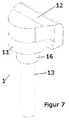
- FIG. 7 This is an L-shaped design and forms the top and front side of the soverschl formulatetikiatas 1.
- the elastic body 11 is cylindrical with a circular base, wherein the end face of the base body 11 is formed flattened and so forms a support for the attachment of the hard body 12.
- FIG. 8 shows a roller 4 with side wear protection elements 1 accordingly FIG. 7
- the grid armor 42 of the roller 4 has arcuate receptacles 45 for the main body 11 of the side wear protection element 1 according to FIG. 7
- This arcuate receptacle 45 encloses the base body 13 (of the side wear protection element 1 according to FIG. 7 ) by more than 180 ° and thus forms an axial fixation of the base body 13.
- contact surfaces 46 are arranged for the hard body 12, which form by their position an anti-rotation device for the hard body 12.
- the side wear protection elements 1 are guided with the threaded bolt 13 through the roller edge 41 and screwed with a nut 5 and intermediate elements 3 are provided.
Landscapes
- Engineering & Computer Science (AREA)
- Food Science & Technology (AREA)
- Mechanical Engineering (AREA)
- Rolls And Other Rotary Bodies (AREA)
- Press Drives And Press Lines (AREA)
- Actuator (AREA)
Abstract
Der erfindungsgemäße Seitenverschleißschutz für die Rolle einer Rollenpresse besteht aus mehreren Seitenverschleißschutzelementen, die die Rollenkante umschließen. Die Seitenverschleißschutzelemente haben erfindungsgemäß einen Grundkörper aus einem elastischen zähen Material. Weiterhin hat der Grundkörper einen Gewindebolzen auf der zur Rollenachse gerichteten Seite des Grundkörpers. Bevorzugt sind auf der Deckseite und der Stirnseite des Grundkörpers Hartkörper befestigt. Die Hartkörper sind bevorzugt aus Hartmetall oder einer hochfeste Eisenlegierung (IFW), zum Beispiel FeCrMoVC gefertigt. Vorteilhaft kann mittels der Erfindung das Volumen des benötigten Hartmetalls erheblich reduziert werden, was einer deutlichen Kosteneinsparung gleich kommt. Passungsprobleme beim Einbau der Hartkörper, wie beim Stand der Technik sind nicht zu befürchten. Auch ist der Ausbau des Seitenverschleißschutzes problemlos durch Lösen der Schraubverbindung möglich, das vormals notwendige aufwendige Erwärmen der Klebverbindung kann entfallen. Vorteilhaft wird die Haltefunktion der Seitenverschleißschutzelemente durch den Grundkörper aus elastischem Material gewährleistet, was die Bruchgefahr erheblich reduziert.The side wear protection for the role of a roller press according to the invention consists of several side wear protection elements which enclose the roller edge. The side wear protection elements according to the invention have a base body made of an elastic tough material. Furthermore, the main body has a threaded bolt on the side facing the roller axis of the body. Preferably, hard bodies are attached to the top side and the front side of the main body. The hard bodies are preferably made of hard metal or a high-strength iron alloy (IFW), for example FeCrMoVC. Advantageously, the volume of the required hard metal can be significantly reduced by means of the invention, which is equivalent to a significant cost savings. Passungsprobleme when installing the hard body, as in the prior art are not to be feared. Also, the expansion of the Seitenverschleißschutzes is easily possible by loosening the screw, the formerly necessary complex heating of the adhesive bond can be omitted. Advantageously, the holding function of the Seitenverschleißschutzelemente is ensured by the body of elastic material, which significantly reduces the risk of breakage.
Description
Die Erfindung bezieht sich auf den Seitenverschleißschutz für Rollen einer Rollenpresse und eine Rolle einer Rollenpresse aufweisend diesen Seitenverschleißschutz.The invention relates to the side wear protection for rolls of a roll press and a roll of a roll press having this side wear protection.
Rollenpressen, auch Gutbett-Walzenmühlen genannt, weisen zwei Rollen gleichen Durchmessers auf, zwischen denen das zu zerkleinernde Material eingebracht wird und dort ein Materialbett bildet. Durch die gegenläufige Rotation der Rollen und den hohen Druck auf das Material zwischen den Rollen erfolgt eine Kompaktierung.Roller presses, also called good-bed roller mills, have two rollers of the same diameter, between which the material to be comminuted is introduced and forms a material bed there. Due to the opposite rotation of the rollers and the high pressure on the material between the rollers is a compaction.
Die Oberflächen der Rollen sind dabei einem hohen Verschleiß ausgesetzt. Aus diesem Grund werden Verschleißschutzschichten auf der Rollenoberfläche eingesetzt. Beispielsweise wird in der
Problematisch erscheint der seitliche Abschluss des Verschleißschutzes. So müssen dort die radialen Presskräfte als auch axiale Kräfte aufgenommen werden. Der Verschleißschutz sollte dabei die äußeren Bereiche der Stirnseiten der Rollen mit umfassen, da seitlich austretendes Material dort zu Verschleiß führt.The lateral conclusion of the wear protection seems problematic. So there the radial pressing forces as well as axial forces must be taken up. The wear protection should include the outer areas of the end faces of the rollers, since laterally emerging material leads to wear there.
In der
Auch wird nachteilig für die Verklebung von großen Klebespalten ein spezieller Klebstoff benötigt. Übergroße Hartkörper führen neben den Problemen bei der Montage und den damit verbundenen Kosten auch zu dem Risiko, dass bei der Montage Anrisse im Hartmetallkörper entstehen, die zu einem späteren Versagen führen. Nicht zuletzt verursacht der Einsatz von Hartmetall sehr hohe Kosten.Also, a special adhesive is disadvantageously required for the bonding of large adhesive gaps. Oversized hard bodies, apart from the problems of assembly and associated costs, also lead to the risk of getting cracks in the assembly Carbide body arise that lead to a later failure. Last but not least, the use of carbide causes very high costs.
Aufgabenstellung der vorliegenden Erfindung ist, einen Seitenverschleißschutz für die Rolle einer Rollenpresse vorzuschlagen, der eine lange Standzeit hat und eine einfache und schnelle Austauschbarkeit ermöglicht.The object of the present invention is to propose a side wear protection for the role of a roller press, which has a long service life and allows easy and quick replacement.
Erfindungsgemäß wird dieser Aufgabe gelöst durch eine Rolle für eine Rollenpresse aufweisend einen Seitenverschleißschutz nach Anspruch 1 und eine Rollenpresse nach Anspruch 14. Bevorzugte Weiterbildungen der Erfindung sind Gegenstand von Unteransprüchen.According to the invention this object is achieved by a roller for a roller press comprising a side wear protection according to
Die erfindungsgemäße Rolle für eine Rollenpresse mit einem Seitenverschleißschutz besteht aus mehreren Seitenverschleißschutzelementen, die die Rollenkante umschließen. Die Seitenverschleißschutzelemente haben erfindungsgemäß einen Grundkörper aus einem elastischen zähen Material. Weiterhin hat der Grundkörper einen Gewindebolzen auf der zur Rollenachse gerichteten Seite des Grundkörpers.The roller according to the invention for a roller press with a side wear protection consists of several side wear protection elements which enclose the roller edge. The side wear protection elements according to the invention have a base body made of an elastic tough material. Furthermore, the main body has a threaded bolt on the side facing the roller axis of the body.
Nachfolgend zur Vereinfachung der Beschreibung eine Definition der Seiten des Grundkörpers bzw. des Seitenverschleißschutzelementes. Im eingebauten Zustand ist die Seite des Grundkörpers, aus der der Gewindebolzen auskragt und die zum Mittelpunkt der Rolle gerichtet ist (also die Kontaktfläche zur Rolle) die Grundseite. Die dieser Seite gegenüberliegende Seite, die die Mantelfläche der Rolle bildet, wird als Deckseite bezeichnet. Die im eingebauten Zustand die Stirnseite der Rolle bildende Seite des Grundkörpers ist die Stirnseite und die der Stirnseite gegenüberliegende Seite, die an die Rasterpanzerung der Rolle angrenzt, ist die Rückseite. Die verbleibenden Seiten, die an die benachbarten Seitenverschleißschutzelemente angrenzen, werden als Ringseiten bezeichnet.Hereinafter, to simplify the description, a definition of the sides of the main body or the Seitenverschleißschutzelementes. When installed, the side of the main body from which the threaded bolt protrudes and which is directed to the center of the role (ie the contact surface to the role) is the base side. The opposite side of this page, which forms the lateral surface of the roll is referred to as the cover page. The in the installed state, the end face of the roller forming side of the body is the front side and the front side opposite side, which is adjacent to the grid armor of the role is the back. The remaining sides adjacent to the adjacent side wear protection elements are referred to as ring sides.
In einer Ausführung ist der Grundkörper quaderförmig. Alternativ können Ringseiten (die Seiten des Grundkörpers, die an andere Seitenverschleißschutzelemente angrenzen) oder auch an die Rasterpanzerung der Rolle so ausgebildet sein, dass ein Formschluss mit den benachbarten Seitenverschleißschutzelementen bzw. der Rasterpanzerung ausgebildet wird.In one embodiment, the basic body is cuboid. Alternatively, ring sides (the sides of the main body which adjoin other side wear protection elements) or also the grid armor of the roller can be designed such that a positive connection is formed with the adjacent side wear protection elements or the grid armor.
In einer alternativen Ausgestaltung ist der Grundkörper zylinderförmig mit einer runden Grundfläche. Bevorzugt ist diese Grundfläche einseitig als Auflage zur Befestigung der Hartkörper abgeflacht.In an alternative embodiment, the base body is cylindrical with a round base. Preferably, this base is flattened on one side as a support for fixing the hard body.
In einer weiteren Ausführung ist die zur Rasterpanzerung der Rolle gerichtete Seite des Grundkörpers (die Rückseite) nach außen, also konvex gewölbt, besonders bevorzugt halbkreisförmig ausgeführt. Die Rasterpanzerung ist korrespondierend konkav ausgeführt. Vorteilhaft kann so die mechanische Stabilität des Seitenverschleißschutzes erhöht werden.In a further embodiment, the side facing the grid armor of the main body (the back) to the outside, ie convex, is particularly preferred Semicircular executed. The grid armor has a corresponding concave design. Advantageously, the mechanical stability of the side wear protection can be increased.
In einer weiteren Ausgestaltung sind auf der Deckseite und der Stirnseite des Grundkörpers Hartkörper befestigt. Die Hartkörper sind bevorzugt aus Hartmetall oder einer hochfeste Eisenlegierung (IFW), zum Beispiel FeCrMoVC gefertigt.In a further embodiment, hard bodies are fastened on the cover side and the front side of the base body. The hard bodies are preferably made of hard metal or a high-strength iron alloy (IFW), for example FeCrMoVC.
In einer alternativen Ausgestaltung ist ein L-förmiger Hartkörper vorgesehen, der Deck- und Stirnseite des Grundkörpers abdeckt. Vorteilhaft muss so nur ein Hartkörper auf dem Grundkörper befestigt werden und die Rollenkante ist vollumfänglich geschützt.In an alternative embodiment, an L-shaped hard body is provided which covers the top and front sides of the base body. Advantageously so only a hard body must be mounted on the body and the roller edge is fully protected.
In einer weiteren Ausführung hat der L-förmige Hartkörper eine nicht rotationssymmetrische Grundform, beispielsweise dreieckförmig, und die Rasterpanzerung der Rolle hat in diesem Bereich Anlageflächen für den Hartkörper. So ist vorteilhaft auf einfache Art und Weise eine Verdrehsicherung für den Grundkörper und damit auch das Seitenverschleißschutzelement gewährleistet.In a further embodiment, the L-shaped hard body has a non-rotationally symmetrical basic shape, for example triangular, and the grid armor of the roller has contact surfaces for the hard body in this area. It is advantageous in a simple manner an anti-rotation for the body and thus also guaranteed the side wear protection.
In einer weiteren Ausführung wird der Grundkörper durch die Rasterpanzerung der Rolle so umschlossen, dass der Grundkörper axial fixiert ist und so vorteilhaft Querkräfte, insbesondere in axialer Richtung von der Rolle weg aufnehmen kann. Beispielsweise kann hierfür der Gundkörper rund ausgeführt sein und die Aufnahme in der Rasterpanzerung umschließt den runden Grundkörper um mehr als 180°.In a further embodiment, the base body is enclosed by the grid armor of the roller so that the base body is axially fixed and so advantageous lateral forces, especially in the axial direction of the roll away can accommodate. For example, for this purpose, the Gundkörper be performed around and the inclusion in the grid armor surrounds the round body by more than 180 °.
Bevorzugt sind die Hartkörper aufgelötet. Alternativ besteht auch die Möglichkeit diese aufzukleben, oder sie gießtechnisch einzubringen. Auch sind Press-, Schraub- und andere mechanische Verbindungen möglich. Zudem sind thermische oder andere Beschichtungen der Verschleißgrundkörper auch denkbar.Preferably, the hard bodies are soldered. Alternatively, it is also possible to glue them, or to introduce them by casting. Also, press, screw and other mechanical connections are possible. In addition, thermal or other coatings of the wear body are also conceivable.
Vorteilhaft kann mittels der Erfindung das Volumen des benötigten Hartmetalls erheblich reduziert werden, was einer deutlichen Kosteneinsparung gleich kommt. Passungsprobleme beim Einbau der Hartkörper, wie beim Stand der Technik sind nicht zu befürchten. Auch ist der Ausbau des Seitenverschleißschutzes problemlos durch Lösen der Schraubverbindung möglich, das vormals notwendige aufwendige Erwärmen der Klebverbindung kann entfallen. Vorteilhaft wird die Haltefunktion der Seitenverschleißschutzelemente durch den Grundkörper aus elastischem Material gewährleistet, was die Bruchgefahr erheblich reduziert.Advantageously, the volume of the required hard metal can be significantly reduced by means of the invention, which is equivalent to a significant cost savings. Passungsprobleme when installing the hard body, as in the prior art are not to be feared. Also, the expansion of the Seitenverschleißschutzes is easily possible by loosening the screw, the formerly necessary complex heating of the adhesive bond can be omitted. Advantageously, the holding function of the Seitenverschleißschutzelemente is ensured by the body of elastic material, which significantly reduces the risk of breakage.
Ein weiterer positiver Effekt ist, dass durch den geringeren Hartmetalleinsatz im Randbereich der Rolle der Badewannenverscheiß, also ein verschleißbedingt zur Rollenmitte hin größerer Verschleiß der zu einem abnehmenden Radius führt, reduziert wird. Vorteilhaft wird so das erforderliche Schleifvolumen zur Beseitigung des badewannenförmigen Verschleißes vermindert.Another positive effect is that due to the lower carbide insert in the edge region of the roller, the bathtub wear, that is to say wear-related to the roller center, leads to greater wear which leads to a decreasing radius. The advantage is that required grinding volume to eliminate the bathtub-shaped wear is reduced.
Bevorzugt sind zwischen Seitenverschleißelement und der Walzenkante Spannstifte angeordnet. Die Spannstifte nehmen axiale oder auch tangentiale Kräfte auf. Die zur Rollenachse gerichtete Seite des Seitenverschleißschutzelementes haben dafür Aufnahmen für die Spannstifte oder die Spannstifte selbst. Besonders bevorzugt sind pro Seitenverschleißschutzelement je zwei Spannstifte im Bereich der Ringseiten angeordnet. Vorteilhaft können durch die Spannstifte auf den Seitenverschleißschutz wirkende axiale und auch tangentiale Kräfte aufgenommen werden. Vorteilhaft gleichen die durch die Bauart bedingten Federmöglichkeiten Toleranzen zwischen den Anlageflächen aus.Preferably, clamping pins are arranged between the side wear element and the roller edge. The dowel pins absorb axial or tangential forces. The directed to the roller axis side of the side wear protection element have recordings for the dowel pins or the dowel pins themselves. Particularly preferred per side wear protection each two dowel pins in the region of the ring sides are arranged. Advantageously, axial and also tangential forces acting on the lateral wear protection by the dowel pins can be absorbed. Advantageously compensate for the spring-related due to the design tolerances between the contact surfaces.
In einer alternativen Ausgestaltung ist der Gewindebolzen gestuft, das heißt nahe dem Grundkörper hat der Gewindebolzen einen Kraftaufnahmebereich mit deutlich größerem Durchmesser. Der verdickte Bereich des Gewindebolzens, der an den Grundkörper angrenzt wird auch als Bund bezeichnet. Der Bund wird im eingebauten Zustand von einem Aufnahmebereich der Rollenkante umgeben, wodurch vorteilhaft die Axial- und Tangentialkräfte aufgenommen werden. Bevorzugt bilden der Bund des Gewindebolzens und der Aufnahmebereich des Bundes in der Rollenkante eine Passung. Vorteilhaft können die Spaltmaße des Seitenverschleißschutzes durch die elastische Aufhängung mittels Gewindebolzen deutlich reduziert werden.In an alternative embodiment, the threaded bolt is stepped, that is close to the main body of the threaded bolt has a force receiving area with a significantly larger diameter. The thickened region of the threaded bolt which adjoins the base body is also referred to as a collar. The collar is surrounded by a receiving area of the roller edge in the installed state, whereby advantageously the axial and tangential forces are absorbed. Preferably, the collar of the threaded bolt and the receiving area of the federal form a fit in the roll edge. Advantageously, the gap dimensions of the Seitenverschleißschutzes can be significantly reduced by the elastic suspension by means of threaded bolts.
Besonders bevorzugt sind elastische, zähe Stahlsorten, insbesondere Vergütungs-, Feinkornbaustähle oder Federstähle. Alternativ können auch andere hochfeste zähe Metalle, z.B. Duraluminium verwendet werden.Particularly preferred are elastic, tough steel grades, in particular tempering, fine grain steels or spring steels. Alternatively, other high strength tough metals, e.g. Duralumin be used.
Weiterhin bevorzugt ist die Auflage des Seitenverschleißschutzelementes auf der Rollenkante eine Linienauflage in axialer Richtung der Rolle. Durch die Linienaufnahme wird eine statisch bestimmte Auflage erreicht und kann vorteilhaft ein Kippeln der Seitenverschleißschutzelemente verhindert werden.Further preferably, the support of the side wear protection element on the roller edge is a line support in the axial direction of the roller. By line recording a statically determined support is achieved and can advantageously be prevented from tipping the Seitenverschleißschutzelemente.
Das Aufsitzen eines Körpers auf zwei Flächen mit unterschiedlichen Winkeln zueinander ist fertigungstechnisch für den Fall, dass der Körper ebenfalls vollflächig auf diesen Flächen aufsitzen soll sehr schwierig und aufwändig herzustellen. Vorteilhaft sind runde Geometrien die dann zu den so angewinkelten Aufstandflächen einen Linienkontakt bilden dort wesentlich einfacher herzustellen.The sitting of a body on two surfaces with different angles to each other is manufacturing technology in the event that the body is also fully flat on these surfaces sit very difficult and expensive to produce. Advantageously, round geometries which form a line contact with the angled contact surfaces are much easier to manufacture.
Die erfindungsgemäße Rolle für eine Rollenpresse hat mindestens ein zuvor beschriebenes Seitenverschleißschutzelement.The roll according to the invention for a roller press has at least one side wear protection element described above.
Dabei ist der Gewindebolzen des Seitenverschleißschutzelementes durch die Rollenkante geführt und verschraubt. Besonders bevorzugt hat die Verschraubung des Gewindebolzens eine Vorspannkraft in radialer Richtung.The threaded bolt of the side wear protection element is guided and screwed through the roller edge. Particularly preferably, the screwing of the threaded bolt has a biasing force in the radial direction.
Weiterhin bevorzugt ist zwischen Seitenverschleißschutzelement und Rollenkante ein Zwischenelement angeordnet. Bevorzugt ist der Gewindebolzen oder ein Spannstift durch das Zwischenelement geführt oder dieses anderweitig in axialer bzw. tangentialer Richtung fixiert, so dass ein Verrutschen verhindert wird. Durch die Auswahl der Dicke der Zwischenelemente ist die Höhe (also der Radius der Rolle) der Seitenverschleißschutzelemente einstellbar. Vorteilhaft kann durch die Höheneinstellung eine Verschleißeinstellung erfolgen und das nach dem Stand der Technik notwendige Nachschleifen der Seitenverschleißschutzelemente zur Verschleißanpassung kann entfallen. Besonders vorteilhaft wird so auch der Austausch eines einzelnen Seitenverschleißschutzelementes erheblich erleichtert, da dessen Höhe über die Zwischenelemente einstellbar ist und ein Schleifen des Hartmetallkörpers zur Höhenanpassung nicht nötig ist. Dieser Vorteil tritt auch beim Einsatz von neuen Seiten - Verschleißelementen zu Tage, das deren Höhe ohne Schleifen über die Zwischenelemente beim Einbau angepasst werden kann.Further preferably, an intermediate element is arranged between the lateral wear protection element and the roller edge. Preferably, the threaded bolt or a dowel pin is guided through the intermediate element or this otherwise fixed in the axial or tangential direction, so that slipping is prevented. By selecting the thickness of the intermediate elements, the height (ie the radius of the roller) of the side wear protection elements is adjustable. Advantageously can be done by the height adjustment a wear adjustment and necessary according to the prior art regrinding the side wear protection elements for wear adjustment can be omitted. Particularly advantageous as well as the exchange of a single side wear protection element is greatly facilitated because its height is adjustable via the intermediate elements and grinding of the hard metal body for height adjustment is not necessary. This advantage is also evident when new side wear elements are used, the height of which can be adjusted without loops via the intermediate elements during installation.
Nachfolgend werden zwei Ausführungsbeispiele der Erfindung anhand von Figuren erläutert. Dabei zeigen:
Figur 1- verschiedene Ansichten eines erfindungsgemäßen Seitenverschleißschutzelementes,
Figur 2- eine Darstellung einer Rollenkante mit erfindungsgemäßen Seitenverschleißschutzelementen entsprechend
den Figuren 1 , Figur 3- eine weitere Ansicht der Rollenkante aus
Figur 2 , Figur 4- eine Seitenansicht der Rollenkante aus
Figur 2 , Figur 5- zwei Ansichten einer alternativen Ausgestaltung eines Seitenverschleißschutzelementes,
- Figur 6
- eine Seitenansicht einer Rollenkante mit
Seitenverschleißschutzelementen nach Figur 5 , - Figur 7
- eine alternative Ausgestaltung eines Verschleißschutzelementes, und
- Figur 8
- eine Rolle mit Verschleißschutzelementen nach
Figur 7 .
- FIG. 1
- various views of a side wear protection element according to the invention,
- FIG. 2
- a representation of a roll edge with side wear protection elements according to the invention according to the
FIGS. 1 . - FIG. 3
- another view of the roll edge
FIG. 2 . - FIG. 4
- a side view of the roll edge
FIG. 2 . - FIG. 5
- two views of an alternative embodiment of a side wear protection element,
- FIG. 6
- a side view of a roller edge with Seitenverschleißschutzelementen after
FIG. 5 . - FIG. 7
- an alternative embodiment of a wear protection element, and
- FIG. 8
- a role with wear protection elements after
FIG. 7 ,
In der
Im eingebauten Zustand ist die Seite des Grundkörpers 11, aus der der Gewindebolzen 13 auskragt, zum Mittelpunkt der Rolle gerichtet, also die Kontaktfläche zur Rolle. Diese Seite wird im hier als Grundseite bezeichnet. Die dieser Seite gegenüberliegende Seite, die die Mantelfläche der Rolle bildet, wird als Deckseite bezeichnet. Die im eingebauten Zustand die Stirnseite der Rolle bildende Seite des Grundkörpers 11 ist die Stirnseite und die der Stirnseite gegenüberliegende Seite, die an die Rasterpanzerung der Rolle angrenzt, ist die Rückseite. Die verbleibenden Seiten, die an die benachbarten Seitenverschleißschutzelemente angrenzen, werden als Ringseiten bezeichnet.When installed, the side of the
Auf der Deckseite und der Stirnseite des Grundkörpers 11 sind Hartkörper 12 aufgelötet. Die Hartkörper 11 bestehen aus Hartmetall oder einer hochfeste Eisenlegierung (IFW). Die Grundseite hat zwei halbkreisförmige Ausnehmungen 15 im Bereich der Ringseiten, die als Aufnahme für Spannstifte 2 dienen. Die Halbkreise sind dabei so angeordnet, dass zwei benachbarte Seitenverschleißschutzelemente 1 eine kreisförmige Ausnehmung bilden, in die ein runder Spannstift einsetzbar ist. Die Grundseite hat zudem zwei kreisförmige Linienauflagen 14, die parallel zu den Ringseiten ausgerichtet sind. Dadurch sind die Linienauflagen 14 zu den zwei unterschiedlich geneigten Ebenen ausgerichtet.On the top side and the front side of the
Die
So wird eine Verzahnung zwischen den Seitenverschleißschutzelementen 1 und der Rasterpanzerung 42 gebildet und ein Rillenverschleiß vermieden, die zusätzliche Stabilität für den Seitenverschleißschutz bietet. Zwischen dem Grundkörper 11 und der Rollenkante 41 ist ein austauschbares Zwischenelement 3 angeordnet, welches zur Einstellung der Höhe (Einbau unterschiedlicher Dicken für die Höhenverstellung) der Seitenverschleißschutzelemente dient. Die Zwischenelemente 3 umschließen die Spannstifte 2 und liegen zudem in einer Vertiefung der Rollenkante 41 und sind so gegen ein Herausfallen gesichert. Die Spannhülsen 2 sitzen in Durchgangsbohrungen und können so durch Ein- und Ausschlagen den verschiedenen Dicken der Zwischenelemente 3 angepasst oder ggf. durch neue ersetzt werden.Thus, a toothing between the side wear
Die
Die Bohrung in der Rollenkante 41 zur Aufnahme des Gewindebolzens 13 hat eine entsprechende Aufnahme 44 für den Bund 16. Die Auswölbung der Rückseite des Seitenverschleißschutzelementes 1 ist bei dieser Ausführung mittig bezogen auf die Rückseite. Das Zwischenelement 3 umschließt hier den Gewindebolzen 13 und ist so lagegesichert.The hole in the
- 11
- SeitenverschleißschutzelementSide wear element
- 1111
- Grundkörperbody
- 1212
- Hartkörperhard body
- 1313
- Gewindebolzenthreaded bolt
- 1414
- Linienauflageline edition
- 1515
- Aufnahme SpannstiftRecording of the tension pin
- 1616
- Stufunggradation
- 22
- Spannstiftdowel pin
- 33
- Zwischenelementintermediate element
- 44
- Rollerole
- 4141
- Rollenkanterole edge
- 4242
- Rasterpanzerunggrid armoring
- 4343
- Wölbungbulge
- 4444
- Aufnahme Bund/ StufungRecording fret / staging
- 4545
- Aufnahme GrundkörperRecording basic body
- 4646
- Anlagefläche HartkörperBearing surface hard body
- 55
- Schraubenmutternut
Claims (15)
dadurch gekennzeichnet, dass
der Grundkörper (11) des Seitenverschleißschutzelementes (1) quaderförmig oder zylindrisch mit runder Grundfläche, die bevorzugt einseitig abgeflacht ist, ist.Roller (4) of a roller press according to claim 1,
characterized in that
the base body (11) of the side wear protection element (1) is cuboidal or cylindrical with a round base, which is preferably flattened on one side.
dadurch gekennzeichnet, dass
die zur Rasterpanzerung (42) der Rolle gerichtete Seite des Grundkörpers (11) des Seitenverschleißschutzelements (1) mindestens eine Wölbung (43) aufweist, bevorzugt eine konkave Wölbung und ansonsten quaderförmig ist.Roller (4) of a roller press according to one of the preceding claims,
characterized in that
the side facing the grid armor (42) of the main body (11) of the Seitenverschleißschutzelements (1) has at least one curvature (43), preferably a concave curvature and otherwise cuboidal.
dadurch gekennzeichnet, dass
auf der im eigebauten Zustand die Mantelfläche und die Stirnseite der Rolle bildenden Seiten des Grundkörpers (11) Hartkörper (12) befestigt sind.Roller (4) of a roller press according to one of the preceding claims,
characterized in that
on the in-built state, the lateral surface and the end face of the roller forming sides of the base body (11) hard body (12) are fixed.
dadurch gekennzeichnet, dass
ein L-förmiger Hartkörper befestigt ist, der sich von der Mantelfläche bis zur Stirnseite der Rolle (4) erstreckt, also die Rollenkante abdeckt.Roller (4) of a roller press according to claim 4,
characterized in that
an L-shaped hard body is attached, which extends from the lateral surface to the front side of the roller (4), thus covering the roller edge.
dadurch gekennzeichnet, dass
der/ die Hartkörper (12) aus Hartmetall oder einer hochfesten Eisenlegierung (IFW) bestehen.Roller (4) of a roller press according to claim 4 or 5,
characterized in that
the hard body (12) made of hard metal or a high-strength iron alloy (IFW) consist.
nach einem der Ansprüche 4 bis 6,
dadurch gekennzeichnet, dass
die Hartkörper (12) aufgelötet sind.Roller (4) of a roller press
according to one of claims 4 to 6,
characterized in that
the hard bodies (12) are soldered.
nach einem der vorangehenden Ansprüche
dadurch gekennzeichnet, dass
auf der zur Rollenkante (41) gerichteten Seite des Grundkörpers (11) Aufnahmen für Spannstifte (15) oder Spannstifte (2) angeordnet sind.Roller (4) of a roller press
according to any one of the preceding claims
characterized in that
On the roller edge (41) directed side of the base body (11) receptacles for dowel pins (15) or dowel pins (2) are arranged.
dadurch gekennzeichnet, dass
der Gewindebolzen (13) gestuft ist und vom Grundkörper (11) ausgehend einen deutlich größeren Durchmesser hat.Roller (4) of a roller press according to one of the preceding claims,
characterized in that
the threaded bolt (13) is stepped and starting from the base body (11) has a significantly larger diameter.
nach einem der vorangehenden Ansprüche
dadurch gekennzeichnet, dass
das elastische Material elastischer zäher Stahl ist.Roller (4) of a roller press
according to any one of the preceding claims
characterized in that
the elastic material is elastic toughened steel.
nach einem der vorangehenden Ansprüche
dadurch gekennzeichnet, dass
die Auflage der Grundkörper (11) auf der Rolle eine Linienauflage (14) in axialer Richtung der Rolle ist.Roller (4) of a roller press
according to any one of the preceding claims
characterized in that
the support of the base body (11) on the roller is a line support (14) in the axial direction of the roller.
nach einem der vorangehenden Ansprüche,
dadurch gekennzeichnet, dass
zwischen Seitenverschleißschutzelement (1) und Rollenkante (41) ein in verschiedenen Dicken auswechselbares Zwischenelement (3) angeordnet ist.role
according to one of the preceding claims,
characterized in that
between side wear protection element (1) and roller edge (41) is arranged in different thicknesses interchangeable intermediate element (3).
dadurch gekennzeichnet, dass
der Gewindebolzen (13) des Seitenverschleißschutzelementes (1) durch eine Rollenkante (41) der Rolle (4) geführt ist und dort verschraubt ist, wobei die Verschraubung eine Vorspannung hat.Roller according to one of the preceding claims,
characterized in that
the threaded bolt (13) of the side wear protection element (1) is guided through a roller edge (41) of the roller (4) and is bolted there, the screw connection having a bias.
dadurch gekennzeichnet, dass
der Grundkörper (11) in der Rasterpanzerung axial fixiert ist und so Querkräfte aufnehmen kann.Roller according to one of the preceding claims,
characterized in that
the base body (11) is axially fixed in the grid armor and so lateral forces can record.
Applications Claiming Priority (1)
| Application Number | Priority Date | Filing Date | Title |
|---|---|---|---|
| DE102015207927.9A DE102015207927A1 (en) | 2015-04-29 | 2015-04-29 | Side wear protection for the role of a roller press |
Publications (2)
| Publication Number | Publication Date |
|---|---|
| EP3088085A1 true EP3088085A1 (en) | 2016-11-02 |
| EP3088085B1 EP3088085B1 (en) | 2020-11-25 |
Family
ID=55862599
Family Applications (1)
| Application Number | Title | Priority Date | Filing Date |
|---|---|---|---|
| EP16167478.3A Active EP3088085B1 (en) | 2015-04-29 | 2016-04-28 | Side sealing protection for the roller in a roller press |
Country Status (9)
| Country | Link |
|---|---|
| US (1) | US20160318025A1 (en) |
| EP (1) | EP3088085B1 (en) |
| AU (1) | AU2016202752B2 (en) |
| CA (1) | CA2928353C (en) |
| CL (1) | CL2016001039A1 (en) |
| DE (1) | DE102015207927A1 (en) |
| EA (1) | EA031311B1 (en) |
| MX (1) | MX2016005615A (en) |
| PE (1) | PE20161088A1 (en) |
Families Citing this family (3)
| Publication number | Priority date | Publication date | Assignee | Title |
|---|---|---|---|---|
| CN104084259B (en) * | 2014-08-01 | 2017-02-22 | 张珂 | Roller and rolling device thereof |
| DE102016200912A1 (en) * | 2016-01-22 | 2017-07-27 | Thyssenkrupp Ag | Wear protection element for a shredding device |
| US11931745B2 (en) * | 2021-06-23 | 2024-03-19 | Metso Outotec USA Inc. | Grinding roll |
Citations (7)
| Publication number | Priority date | Publication date | Assignee | Title |
|---|---|---|---|---|
| EP0443195A1 (en) | 1990-02-22 | 1991-08-28 | Klöckner-Humboldt-Deutz Aktiengesellschaft | Abrasion-resistant cladding for the roller surfaces of roller machines, in particular high-pressure roller presses |
| DE4132474A1 (en) | 1991-05-28 | 1992-12-03 | Kloeckner Humboldt Deutz Ag | WEAR-RESISTANT GRINDING ROLLER FOR USE IN ROLLING MACHINES, ESPECIALLY IN HIGH PRESSURE ROLLING PRESSES |
| EP1684907B1 (en) | 2003-11-22 | 2008-12-24 | KHD Humboldt Wedag GmbH | Grinding roll for pressure grinding granular material |
| DE102010024221A1 (en) | 2010-06-18 | 2011-12-22 | Khd Humboldt Wedag Gmbh | Profiled bandage for a roller press |
| WO2013066933A1 (en) * | 2011-10-31 | 2013-05-10 | Flsmidth A/S | Edge protection for roller presses |
| EP2653230A2 (en) * | 2012-04-20 | 2013-10-23 | Metso Minerals Industries, Inc. | Crushing roll with edge protection |
| US20140361108A1 (en) * | 2011-12-27 | 2014-12-11 | Flsmidth A/S | Edge protection insert mounts for grinding rolls |
Family Cites Families (3)
| Publication number | Priority date | Publication date | Assignee | Title |
|---|---|---|---|---|
| DE10335115A1 (en) * | 2003-07-31 | 2005-02-24 | Polysius Ag | grinding roll |
| DE102012102199A1 (en) * | 2012-03-15 | 2013-09-19 | Maschinenfabrik Köppern GmbH & Co KG | press roll |
| WO2014071173A2 (en) * | 2012-10-31 | 2014-05-08 | Flsmidth A/S | Edge protection with internal threaded receiving securement |
-
2015
- 2015-04-29 DE DE102015207927.9A patent/DE102015207927A1/en not_active Withdrawn
-
2016
- 2016-04-27 PE PE2016000561A patent/PE20161088A1/en unknown
- 2016-04-27 EA EA201600294A patent/EA031311B1/en not_active IP Right Cessation
- 2016-04-28 CA CA2928353A patent/CA2928353C/en active Active
- 2016-04-28 EP EP16167478.3A patent/EP3088085B1/en active Active
- 2016-04-29 US US15/142,874 patent/US20160318025A1/en not_active Abandoned
- 2016-04-29 CL CL2016001039A patent/CL2016001039A1/en unknown
- 2016-04-29 AU AU2016202752A patent/AU2016202752B2/en active Active
- 2016-04-29 MX MX2016005615A patent/MX2016005615A/en unknown
Patent Citations (7)
| Publication number | Priority date | Publication date | Assignee | Title |
|---|---|---|---|---|
| EP0443195A1 (en) | 1990-02-22 | 1991-08-28 | Klöckner-Humboldt-Deutz Aktiengesellschaft | Abrasion-resistant cladding for the roller surfaces of roller machines, in particular high-pressure roller presses |
| DE4132474A1 (en) | 1991-05-28 | 1992-12-03 | Kloeckner Humboldt Deutz Ag | WEAR-RESISTANT GRINDING ROLLER FOR USE IN ROLLING MACHINES, ESPECIALLY IN HIGH PRESSURE ROLLING PRESSES |
| EP1684907B1 (en) | 2003-11-22 | 2008-12-24 | KHD Humboldt Wedag GmbH | Grinding roll for pressure grinding granular material |
| DE102010024221A1 (en) | 2010-06-18 | 2011-12-22 | Khd Humboldt Wedag Gmbh | Profiled bandage for a roller press |
| WO2013066933A1 (en) * | 2011-10-31 | 2013-05-10 | Flsmidth A/S | Edge protection for roller presses |
| US20140361108A1 (en) * | 2011-12-27 | 2014-12-11 | Flsmidth A/S | Edge protection insert mounts for grinding rolls |
| EP2653230A2 (en) * | 2012-04-20 | 2013-10-23 | Metso Minerals Industries, Inc. | Crushing roll with edge protection |
Also Published As
| Publication number | Publication date |
|---|---|
| MX2016005615A (en) | 2016-10-31 |
| DE102015207927A1 (en) | 2016-11-03 |
| EA201600294A3 (en) | 2016-11-30 |
| EA201600294A8 (en) | 2018-11-30 |
| CL2016001039A1 (en) | 2017-02-17 |
| CA2928353A1 (en) | 2016-10-29 |
| EA031311B1 (en) | 2018-12-28 |
| US20160318025A1 (en) | 2016-11-03 |
| AU2016202752A1 (en) | 2016-11-17 |
| PE20161088A1 (en) | 2016-10-22 |
| EP3088085B1 (en) | 2020-11-25 |
| EA201600294A2 (en) | 2016-10-31 |
| AU2016202752B2 (en) | 2017-07-20 |
| CA2928353C (en) | 2018-05-01 |
Similar Documents
| Publication | Publication Date | Title |
|---|---|---|
| EP2997278B2 (en) | Caliper disc brake of a vehicle | |
| EP2997277B1 (en) | Caliper disc brake of a vehicle, in particular a commercial vehicle, and holding-down spring of such a brake | |
| DE102009000900B4 (en) | Improved rack housing press connection | |
| EP2444183A1 (en) | Front end actuator | |
| EP3088085B1 (en) | Side sealing protection for the roller in a roller press | |
| EP1963653A1 (en) | Multipart piston for an internal combustion engine | |
| DE102016117104A1 (en) | Multi-part, spring-loaded rail wheel | |
| AT519652A4 (en) | Sealing device and hydraulic piston with sealing device | |
| DE2334212A1 (en) | ASSEMBLED ROLLER | |
| DE1555850C3 (en) | Vibrating actuator | |
| EP1509308A1 (en) | Device for filtering fluids that are conveyed under a high pressure | |
| DE102007023191B4 (en) | Disc brake for a commercial vehicle | |
| DE4013896C1 (en) | Pre-tension adjuster for ball bearings - has end of sleeve bearing against fixed end-stop in housing | |
| WO2007110057A1 (en) | Multipart piston for an internal combustion engine | |
| DE102015103088A1 (en) | Clamping device of a disc brake | |
| DE102014115766B4 (en) | Disc brake for a commercial vehicle | |
| DE102014105418B4 (en) | Disc brake for a commercial vehicle | |
| DE102012020630A1 (en) | Hydraulic valve arrangement | |
| DE202012002798U1 (en) | joint line | |
| DE202012002799U1 (en) | joint line | |
| DE102015119509A1 (en) | Disc brake and brake pad set | |
| DE102008038272B4 (en) | milling tool | |
| AT525340A1 (en) | valve for a pump | |
| DE286071C (en) | ||
| DE3739483A1 (en) | Gate valve |
Legal Events
| Date | Code | Title | Description |
|---|---|---|---|
| PUAI | Public reference made under article 153(3) epc to a published international application that has entered the european phase |
Free format text: ORIGINAL CODE: 0009012 |
|
| AK | Designated contracting states |
Kind code of ref document: A1 Designated state(s): AL AT BE BG CH CY CZ DE DK EE ES FI FR GB GR HR HU IE IS IT LI LT LU LV MC MK MT NL NO PL PT RO RS SE SI SK SM TR |
|
| AX | Request for extension of the european patent |
Extension state: BA ME |
|
| STAA | Information on the status of an ep patent application or granted ep patent |
Free format text: STATUS: REQUEST FOR EXAMINATION WAS MADE |
|
| 17P | Request for examination filed |
Effective date: 20170214 |
|
| RBV | Designated contracting states (corrected) |
Designated state(s): AL AT BE BG CH CY CZ DE DK EE ES FI FR GB GR HR HU IE IS IT LI LT LU LV MC MK MT NL NO PL PT RO RS SE SI SK SM TR |
|
| REG | Reference to a national code |
Ref country code: DE Ref legal event code: R079 Ref document number: 502016011761 Country of ref document: DE Free format text: PREVIOUS MAIN CLASS: B02C0004300000 Ipc: B02C0004320000 |
|
| GRAP | Despatch of communication of intention to grant a patent |
Free format text: ORIGINAL CODE: EPIDOSNIGR1 |
|
| STAA | Information on the status of an ep patent application or granted ep patent |
Free format text: STATUS: GRANT OF PATENT IS INTENDED |
|
| RIC1 | Information provided on ipc code assigned before grant |
Ipc: B02C 4/32 20060101AFI20200617BHEP Ipc: B30B 3/00 20060101ALI20200617BHEP Ipc: B02C 4/30 20060101ALI20200617BHEP |
|
| INTG | Intention to grant announced |
Effective date: 20200707 |
|
| GRAS | Grant fee paid |
Free format text: ORIGINAL CODE: EPIDOSNIGR3 |
|
| GRAA | (expected) grant |
Free format text: ORIGINAL CODE: 0009210 |
|
| STAA | Information on the status of an ep patent application or granted ep patent |
Free format text: STATUS: THE PATENT HAS BEEN GRANTED |
|
| AK | Designated contracting states |
Kind code of ref document: B1 Designated state(s): AL AT BE BG CH CY CZ DE DK EE ES FI FR GB GR HR HU IE IS IT LI LT LU LV MC MK MT NL NO PL PT RO RS SE SI SK SM TR |
|
| REG | Reference to a national code |
Ref country code: GB Ref legal event code: FG4D Free format text: NOT ENGLISH |
|
| REG | Reference to a national code |
Ref country code: CH Ref legal event code: EP |
|
| REG | Reference to a national code |
Ref country code: DE Ref legal event code: R082 Ref document number: 502016011761 Country of ref document: DE Representative=s name: KAILUWEIT & UHLEMANN PATENTANWAELTE PARTNERSCH, DE |
|
| REG | Reference to a national code |
Ref country code: AT Ref legal event code: REF Ref document number: 1337673 Country of ref document: AT Kind code of ref document: T Effective date: 20201215 |
|
| REG | Reference to a national code |
Ref country code: DE Ref legal event code: R096 Ref document number: 502016011761 Country of ref document: DE |
|
| REG | Reference to a national code |
Ref country code: IE Ref legal event code: FG4D Free format text: LANGUAGE OF EP DOCUMENT: GERMAN |
|
| REG | Reference to a national code |
Ref country code: NL Ref legal event code: FP |
|
| REG | Reference to a national code |
Ref country code: FI Ref legal event code: FGE |
|
| PG25 | Lapsed in a contracting state [announced via postgrant information from national office to epo] |
Ref country code: GR Free format text: LAPSE BECAUSE OF FAILURE TO SUBMIT A TRANSLATION OF THE DESCRIPTION OR TO PAY THE FEE WITHIN THE PRESCRIBED TIME-LIMIT Effective date: 20210226 Ref country code: RS Free format text: LAPSE BECAUSE OF FAILURE TO SUBMIT A TRANSLATION OF THE DESCRIPTION OR TO PAY THE FEE WITHIN THE PRESCRIBED TIME-LIMIT Effective date: 20201125 Ref country code: PT Free format text: LAPSE BECAUSE OF FAILURE TO SUBMIT A TRANSLATION OF THE DESCRIPTION OR TO PAY THE FEE WITHIN THE PRESCRIBED TIME-LIMIT Effective date: 20210325 Ref country code: NO Free format text: LAPSE BECAUSE OF FAILURE TO SUBMIT A TRANSLATION OF THE DESCRIPTION OR TO PAY THE FEE WITHIN THE PRESCRIBED TIME-LIMIT Effective date: 20210225 |
|
| PG25 | Lapsed in a contracting state [announced via postgrant information from national office to epo] |
Ref country code: BG Free format text: LAPSE BECAUSE OF FAILURE TO SUBMIT A TRANSLATION OF THE DESCRIPTION OR TO PAY THE FEE WITHIN THE PRESCRIBED TIME-LIMIT Effective date: 20210225 Ref country code: PL Free format text: LAPSE BECAUSE OF FAILURE TO SUBMIT A TRANSLATION OF THE DESCRIPTION OR TO PAY THE FEE WITHIN THE PRESCRIBED TIME-LIMIT Effective date: 20201125 Ref country code: SE Free format text: LAPSE BECAUSE OF FAILURE TO SUBMIT A TRANSLATION OF THE DESCRIPTION OR TO PAY THE FEE WITHIN THE PRESCRIBED TIME-LIMIT Effective date: 20201125 Ref country code: IS Free format text: LAPSE BECAUSE OF FAILURE TO SUBMIT A TRANSLATION OF THE DESCRIPTION OR TO PAY THE FEE WITHIN THE PRESCRIBED TIME-LIMIT Effective date: 20210325 Ref country code: LV Free format text: LAPSE BECAUSE OF FAILURE TO SUBMIT A TRANSLATION OF THE DESCRIPTION OR TO PAY THE FEE WITHIN THE PRESCRIBED TIME-LIMIT Effective date: 20201125 |
|
| REG | Reference to a national code |
Ref country code: LT Ref legal event code: MG9D |
|
| PG25 | Lapsed in a contracting state [announced via postgrant information from national office to epo] |
Ref country code: HR Free format text: LAPSE BECAUSE OF FAILURE TO SUBMIT A TRANSLATION OF THE DESCRIPTION OR TO PAY THE FEE WITHIN THE PRESCRIBED TIME-LIMIT Effective date: 20201125 |
|
| PG25 | Lapsed in a contracting state [announced via postgrant information from national office to epo] |
Ref country code: EE Free format text: LAPSE BECAUSE OF FAILURE TO SUBMIT A TRANSLATION OF THE DESCRIPTION OR TO PAY THE FEE WITHIN THE PRESCRIBED TIME-LIMIT Effective date: 20201125 Ref country code: CZ Free format text: LAPSE BECAUSE OF FAILURE TO SUBMIT A TRANSLATION OF THE DESCRIPTION OR TO PAY THE FEE WITHIN THE PRESCRIBED TIME-LIMIT Effective date: 20201125 Ref country code: LT Free format text: LAPSE BECAUSE OF FAILURE TO SUBMIT A TRANSLATION OF THE DESCRIPTION OR TO PAY THE FEE WITHIN THE PRESCRIBED TIME-LIMIT Effective date: 20201125 Ref country code: SM Free format text: LAPSE BECAUSE OF FAILURE TO SUBMIT A TRANSLATION OF THE DESCRIPTION OR TO PAY THE FEE WITHIN THE PRESCRIBED TIME-LIMIT Effective date: 20201125 Ref country code: RO Free format text: LAPSE BECAUSE OF FAILURE TO SUBMIT A TRANSLATION OF THE DESCRIPTION OR TO PAY THE FEE WITHIN THE PRESCRIBED TIME-LIMIT Effective date: 20201125 Ref country code: SK Free format text: LAPSE BECAUSE OF FAILURE TO SUBMIT A TRANSLATION OF THE DESCRIPTION OR TO PAY THE FEE WITHIN THE PRESCRIBED TIME-LIMIT Effective date: 20201125 |
|
| REG | Reference to a national code |
Ref country code: DE Ref legal event code: R097 Ref document number: 502016011761 Country of ref document: DE |
|
| PG25 | Lapsed in a contracting state [announced via postgrant information from national office to epo] |
Ref country code: DK Free format text: LAPSE BECAUSE OF FAILURE TO SUBMIT A TRANSLATION OF THE DESCRIPTION OR TO PAY THE FEE WITHIN THE PRESCRIBED TIME-LIMIT Effective date: 20201125 |
|
| PLBE | No opposition filed within time limit |
Free format text: ORIGINAL CODE: 0009261 |
|
| STAA | Information on the status of an ep patent application or granted ep patent |
Free format text: STATUS: NO OPPOSITION FILED WITHIN TIME LIMIT |
|
| PG25 | Lapsed in a contracting state [announced via postgrant information from national office to epo] |
Ref country code: AL Free format text: LAPSE BECAUSE OF FAILURE TO SUBMIT A TRANSLATION OF THE DESCRIPTION OR TO PAY THE FEE WITHIN THE PRESCRIBED TIME-LIMIT Effective date: 20201125 Ref country code: IT Free format text: LAPSE BECAUSE OF FAILURE TO SUBMIT A TRANSLATION OF THE DESCRIPTION OR TO PAY THE FEE WITHIN THE PRESCRIBED TIME-LIMIT Effective date: 20201125 |
|
| 26N | No opposition filed |
Effective date: 20210826 |
|
| PG25 | Lapsed in a contracting state [announced via postgrant information from national office to epo] |
Ref country code: SI Free format text: LAPSE BECAUSE OF FAILURE TO SUBMIT A TRANSLATION OF THE DESCRIPTION OR TO PAY THE FEE WITHIN THE PRESCRIBED TIME-LIMIT Effective date: 20201125 Ref country code: ES Free format text: LAPSE BECAUSE OF FAILURE TO SUBMIT A TRANSLATION OF THE DESCRIPTION OR TO PAY THE FEE WITHIN THE PRESCRIBED TIME-LIMIT Effective date: 20201125 Ref country code: MC Free format text: LAPSE BECAUSE OF FAILURE TO SUBMIT A TRANSLATION OF THE DESCRIPTION OR TO PAY THE FEE WITHIN THE PRESCRIBED TIME-LIMIT Effective date: 20201125 |
|
| PG25 | Lapsed in a contracting state [announced via postgrant information from national office to epo] |
Ref country code: LU Free format text: LAPSE BECAUSE OF NON-PAYMENT OF DUE FEES Effective date: 20210428 |
|
| REG | Reference to a national code |
Ref country code: BE Ref legal event code: MM Effective date: 20210430 |
|
| PG25 | Lapsed in a contracting state [announced via postgrant information from national office to epo] |
Ref country code: CH Free format text: LAPSE BECAUSE OF NON-PAYMENT OF DUE FEES Effective date: 20210430 Ref country code: LI Free format text: LAPSE BECAUSE OF NON-PAYMENT OF DUE FEES Effective date: 20210430 Ref country code: FR Free format text: LAPSE BECAUSE OF NON-PAYMENT OF DUE FEES Effective date: 20210430 |
|
| PG25 | Lapsed in a contracting state [announced via postgrant information from national office to epo] |
Ref country code: IE Free format text: LAPSE BECAUSE OF NON-PAYMENT OF DUE FEES Effective date: 20210428 |
|
| PG25 | Lapsed in a contracting state [announced via postgrant information from national office to epo] |
Ref country code: IS Free format text: LAPSE BECAUSE OF FAILURE TO SUBMIT A TRANSLATION OF THE DESCRIPTION OR TO PAY THE FEE WITHIN THE PRESCRIBED TIME-LIMIT Effective date: 20210325 |
|
| REG | Reference to a national code |
Ref country code: AT Ref legal event code: MM01 Ref document number: 1337673 Country of ref document: AT Kind code of ref document: T Effective date: 20210428 |
|
| PG25 | Lapsed in a contracting state [announced via postgrant information from national office to epo] |
Ref country code: BE Free format text: LAPSE BECAUSE OF NON-PAYMENT OF DUE FEES Effective date: 20210430 |
|
| PG25 | Lapsed in a contracting state [announced via postgrant information from national office to epo] |
Ref country code: AT Free format text: LAPSE BECAUSE OF NON-PAYMENT OF DUE FEES Effective date: 20210428 |
|
| PG25 | Lapsed in a contracting state [announced via postgrant information from national office to epo] |
Ref country code: HU Free format text: LAPSE BECAUSE OF FAILURE TO SUBMIT A TRANSLATION OF THE DESCRIPTION OR TO PAY THE FEE WITHIN THE PRESCRIBED TIME-LIMIT; INVALID AB INITIO Effective date: 20160428 |
|
| P01 | Opt-out of the competence of the unified patent court (upc) registered |
Effective date: 20230516 |
|
| PG25 | Lapsed in a contracting state [announced via postgrant information from national office to epo] |
Ref country code: CY Free format text: LAPSE BECAUSE OF FAILURE TO SUBMIT A TRANSLATION OF THE DESCRIPTION OR TO PAY THE FEE WITHIN THE PRESCRIBED TIME-LIMIT Effective date: 20201125 |
|
| PGFP | Annual fee paid to national office [announced via postgrant information from national office to epo] |
Ref country code: NL Payment date: 20230417 Year of fee payment: 8 |
|
| PGFP | Annual fee paid to national office [announced via postgrant information from national office to epo] |
Ref country code: DE Payment date: 20230130 Year of fee payment: 8 |
|
| PGFP | Annual fee paid to national office [announced via postgrant information from national office to epo] |
Ref country code: FI Payment date: 20230417 Year of fee payment: 8 |
|
| PGFP | Annual fee paid to national office [announced via postgrant information from national office to epo] |
Ref country code: GB Payment date: 20230420 Year of fee payment: 8 |