EP3087332B1 - Kühlaggregat mit intermittierendem stromnetz - Google Patents
Kühlaggregat mit intermittierendem stromnetz Download PDFInfo
- Publication number
- EP3087332B1 EP3087332B1 EP14874552.4A EP14874552A EP3087332B1 EP 3087332 B1 EP3087332 B1 EP 3087332B1 EP 14874552 A EP14874552 A EP 14874552A EP 3087332 B1 EP3087332 B1 EP 3087332B1
- Authority
- EP
- European Patent Office
- Prior art keywords
- cooler
- phase change
- change material
- shelf
- shelf assemblies
- Prior art date
- Legal status (The legal status is an assumption and is not a legal conclusion. Google has not performed a legal analysis and makes no representation as to the accuracy of the status listed.)
- Active
Links
- 239000012782 phase change material Substances 0.000 claims description 66
- 238000005057 refrigeration Methods 0.000 claims description 34
- 230000000712 assembly Effects 0.000 claims description 33
- 238000000429 assembly Methods 0.000 claims description 33
- XLYOFNOQVPJJNP-UHFFFAOYSA-N water Substances O XLYOFNOQVPJJNP-UHFFFAOYSA-N 0.000 claims description 8
- 238000007710 freezing Methods 0.000 claims description 6
- 230000008014 freezing Effects 0.000 claims description 6
- 239000003507 refrigerant Substances 0.000 claims description 6
- 238000004891 communication Methods 0.000 claims description 5
- 238000009413 insulation Methods 0.000 claims description 5
- 238000000034 method Methods 0.000 claims description 5
- 230000008602 contraction Effects 0.000 claims description 4
- 230000008859 change Effects 0.000 claims description 3
- 238000002844 melting Methods 0.000 claims description 3
- 230000008018 melting Effects 0.000 claims description 3
- 210000000038 chest Anatomy 0.000 description 5
- LYCAIKOWRPUZTN-UHFFFAOYSA-N Ethylene glycol Chemical compound OCCO LYCAIKOWRPUZTN-UHFFFAOYSA-N 0.000 description 4
- 239000011521 glass Substances 0.000 description 4
- 235000013361 beverage Nutrition 0.000 description 2
- 239000012267 brine Substances 0.000 description 2
- 230000003247 decreasing effect Effects 0.000 description 2
- 238000013461 design Methods 0.000 description 2
- 238000010586 diagram Methods 0.000 description 2
- WGCNASOHLSPBMP-UHFFFAOYSA-N hydroxyacetaldehyde Natural products OCC=O WGCNASOHLSPBMP-UHFFFAOYSA-N 0.000 description 2
- 239000000155 melt Substances 0.000 description 2
- 239000000203 mixture Substances 0.000 description 2
- HPALAKNZSZLMCH-UHFFFAOYSA-M sodium;chloride;hydrate Chemical compound O.[Na+].[Cl-] HPALAKNZSZLMCH-UHFFFAOYSA-M 0.000 description 2
- 238000013517 stratification Methods 0.000 description 2
- 238000012546 transfer Methods 0.000 description 2
- 230000005678 Seebeck effect Effects 0.000 description 1
- 229920006397 acrylic thermoplastic Polymers 0.000 description 1
- 239000003990 capacitor Substances 0.000 description 1
- 235000020965 cold beverage Nutrition 0.000 description 1
- 238000009833 condensation Methods 0.000 description 1
- 238000001816 cooling Methods 0.000 description 1
- 239000000428 dust Substances 0.000 description 1
- 238000009459 flexible packaging Methods 0.000 description 1
- 239000006261 foam material Substances 0.000 description 1
- 239000011888 foil Substances 0.000 description 1
- 238000011065 in-situ storage Methods 0.000 description 1
- 230000007774 longterm Effects 0.000 description 1
- 239000000463 material Substances 0.000 description 1
- 229910052751 metal Inorganic materials 0.000 description 1
- 239000002184 metal Substances 0.000 description 1
- 150000002739 metals Chemical class 0.000 description 1
- 238000013508 migration Methods 0.000 description 1
- 230000005012 migration Effects 0.000 description 1
- 238000012986 modification Methods 0.000 description 1
- 230000004048 modification Effects 0.000 description 1
- 230000008447 perception Effects 0.000 description 1
- 229920003229 poly(methyl methacrylate) Polymers 0.000 description 1
- 230000008569 process Effects 0.000 description 1
- 230000009467 reduction Effects 0.000 description 1
- 238000012552 review Methods 0.000 description 1
- 239000000523 sample Substances 0.000 description 1
- 238000000926 separation method Methods 0.000 description 1
- 239000000243 solution Substances 0.000 description 1
- ISXSCDLOGDJUNJ-UHFFFAOYSA-N tert-butyl prop-2-enoate Chemical compound CC(C)(C)OC(=O)C=C ISXSCDLOGDJUNJ-UHFFFAOYSA-N 0.000 description 1
- 230000000007 visual effect Effects 0.000 description 1
Images


Classifications
-
- F—MECHANICAL ENGINEERING; LIGHTING; HEATING; WEAPONS; BLASTING
- F25—REFRIGERATION OR COOLING; COMBINED HEATING AND REFRIGERATION SYSTEMS; HEAT PUMP SYSTEMS; MANUFACTURE OR STORAGE OF ICE; LIQUEFACTION SOLIDIFICATION OF GASES
- F25D—REFRIGERATORS; COLD ROOMS; ICE-BOXES; COOLING OR FREEZING APPARATUS NOT OTHERWISE PROVIDED FOR
- F25D16/00—Devices using a combination of a cooling mode associated with refrigerating machinery with a cooling mode not associated with refrigerating machinery
-
- A—HUMAN NECESSITIES
- A47—FURNITURE; DOMESTIC ARTICLES OR APPLIANCES; COFFEE MILLS; SPICE MILLS; SUCTION CLEANERS IN GENERAL
- A47F—SPECIAL FURNITURE, FITTINGS, OR ACCESSORIES FOR SHOPS, STOREHOUSES, BARS, RESTAURANTS OR THE LIKE; PAYING COUNTERS
- A47F3/00—Show cases or show cabinets
- A47F3/04—Show cases or show cabinets air-conditioned, refrigerated
- A47F3/0404—Cases or cabinets of the closed type
- A47F3/0426—Details
- A47F3/043—Doors, covers
-
- F—MECHANICAL ENGINEERING; LIGHTING; HEATING; WEAPONS; BLASTING
- F25—REFRIGERATION OR COOLING; COMBINED HEATING AND REFRIGERATION SYSTEMS; HEAT PUMP SYSTEMS; MANUFACTURE OR STORAGE OF ICE; LIQUEFACTION SOLIDIFICATION OF GASES
- F25B—REFRIGERATION MACHINES, PLANTS OR SYSTEMS; COMBINED HEATING AND REFRIGERATION SYSTEMS; HEAT PUMP SYSTEMS
- F25B39/00—Evaporators; Condensers
- F25B39/02—Evaporators
-
- F—MECHANICAL ENGINEERING; LIGHTING; HEATING; WEAPONS; BLASTING
- F25—REFRIGERATION OR COOLING; COMBINED HEATING AND REFRIGERATION SYSTEMS; HEAT PUMP SYSTEMS; MANUFACTURE OR STORAGE OF ICE; LIQUEFACTION SOLIDIFICATION OF GASES
- F25B—REFRIGERATION MACHINES, PLANTS OR SYSTEMS; COMBINED HEATING AND REFRIGERATION SYSTEMS; HEAT PUMP SYSTEMS
- F25B5/00—Compression machines, plants or systems, with several evaporator circuits, e.g. for varying refrigerating capacity
- F25B5/04—Compression machines, plants or systems, with several evaporator circuits, e.g. for varying refrigerating capacity arranged in series
-
- F—MECHANICAL ENGINEERING; LIGHTING; HEATING; WEAPONS; BLASTING
- F25—REFRIGERATION OR COOLING; COMBINED HEATING AND REFRIGERATION SYSTEMS; HEAT PUMP SYSTEMS; MANUFACTURE OR STORAGE OF ICE; LIQUEFACTION SOLIDIFICATION OF GASES
- F25D—REFRIGERATORS; COLD ROOMS; ICE-BOXES; COOLING OR FREEZING APPARATUS NOT OTHERWISE PROVIDED FOR
- F25D11/00—Self-contained movable devices, e.g. domestic refrigerators
- F25D11/006—Self-contained movable devices, e.g. domestic refrigerators with cold storage accumulators
-
- F—MECHANICAL ENGINEERING; LIGHTING; HEATING; WEAPONS; BLASTING
- F25—REFRIGERATION OR COOLING; COMBINED HEATING AND REFRIGERATION SYSTEMS; HEAT PUMP SYSTEMS; MANUFACTURE OR STORAGE OF ICE; LIQUEFACTION SOLIDIFICATION OF GASES
- F25D—REFRIGERATORS; COLD ROOMS; ICE-BOXES; COOLING OR FREEZING APPARATUS NOT OTHERWISE PROVIDED FOR
- F25D25/00—Charging, supporting, and discharging the articles to be cooled
- F25D25/02—Charging, supporting, and discharging the articles to be cooled by shelves
- F25D25/028—Cooled supporting means
-
- F—MECHANICAL ENGINEERING; LIGHTING; HEATING; WEAPONS; BLASTING
- F25—REFRIGERATION OR COOLING; COMBINED HEATING AND REFRIGERATION SYSTEMS; HEAT PUMP SYSTEMS; MANUFACTURE OR STORAGE OF ICE; LIQUEFACTION SOLIDIFICATION OF GASES
- F25D—REFRIGERATORS; COLD ROOMS; ICE-BOXES; COOLING OR FREEZING APPARATUS NOT OTHERWISE PROVIDED FOR
- F25D27/00—Lighting arrangements
-
- F—MECHANICAL ENGINEERING; LIGHTING; HEATING; WEAPONS; BLASTING
- F25—REFRIGERATION OR COOLING; COMBINED HEATING AND REFRIGERATION SYSTEMS; HEAT PUMP SYSTEMS; MANUFACTURE OR STORAGE OF ICE; LIQUEFACTION SOLIDIFICATION OF GASES
- F25D—REFRIGERATORS; COLD ROOMS; ICE-BOXES; COOLING OR FREEZING APPARATUS NOT OTHERWISE PROVIDED FOR
- F25D3/00—Devices using other cold materials; Devices using cold-storage bodies
-
- F—MECHANICAL ENGINEERING; LIGHTING; HEATING; WEAPONS; BLASTING
- F25—REFRIGERATION OR COOLING; COMBINED HEATING AND REFRIGERATION SYSTEMS; HEAT PUMP SYSTEMS; MANUFACTURE OR STORAGE OF ICE; LIQUEFACTION SOLIDIFICATION OF GASES
- F25B—REFRIGERATION MACHINES, PLANTS OR SYSTEMS; COMBINED HEATING AND REFRIGERATION SYSTEMS; HEAT PUMP SYSTEMS
- F25B2400/00—General features or devices for refrigeration machines, plants or systems, combined heating and refrigeration systems or heat-pump systems, i.e. not limited to a particular subgroup of F25B
- F25B2400/24—Storage receiver heat
Definitions
- the present application and the resultant patent relates generally to refrigeration systems and more particularly relate to a cooler such as a glass door merchandiser that may accommodate intermittent power while maintaining the products therein cooled and appealing.
- ice blocks may keep the products therein cool for a longer period of time, but such ice blocks may be difficult to handle and generally may be positioned at the top of a cooler such that the cooler as a whole may be unstable and/or have a large footprint.
- an improved cooler such as a glass door merchandiser and the like.
- a cooler may accommodate intermittent electric power while maintaining the products therein in a cooled condition for an extended period of time.
- the cooler may have an improved energy efficient configuration with improved merchandising capability so as to indicate the presence of cooled products therein
- Coolers of the prior art making use of evaporator coils and phase change material cells in their shelf assemblies are known from patent publications EP1124101 , US4459826 , EP0098052 and WO9405959 .
- the present disclosure thus provides cooler according to claim 1.
- the cooler includes an outer frame, a product space within the outer frame, and a number of shelf assemblies positioned within the product space.
- the shelf assemblies include an evaporator and a phase change material therein.
- the present disclosure further provides a method of operating a cooler with intermittent power according to claim 13.
- the method includes the steps of positioning a number of shelf assemblies within the cooler wherein the shelf assemblies include a phase change material and an evaporator therein, circulating a refrigerant about the phase change material when the power is on, freezing the phase change material, and maintaining the cooler in a chilled condition for an extended period of time when the power is off by melting the phase change material.
- the product space may include a substantially hexagonal shape.
- the products may be arranged in a zig-zag configuration.
- the cooler may include a Seebeck indicator in thermal communication with the outer frame and the product space so as to indicate the presence of cooled products therein.
- the cooler may include a product space with a substantially hexagonal shape within the outer frame, a number of products arranged in the product space in a zig-zag configuration, and one or more replaceable phase change material packs positioned about the product space.
- the present application and the resultant patent concern the offering for sale of any number of products 10.
- the products 10 are shown, by way of example only, in the form of bottles, it is understood that the products 10 may include any type or size of item or package including, but not limited to, bottles, cans, pouches, boxes, wrapped items, produce, and/or any type of rigid or flexible packaging.
- the products 10 may include beverages, food items, non-food items, consumer products, and/or any type of product.
- the scope of the application herein is in no way limited by the nature of the products 10 described herein.
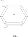
- Figs. 1-6 show an example of a cooler 100 as may be described herein.
- the cooler 100 may be a hexagonally-shaped cooler 110.
- the cooler 100 may have any suitable size, shape, or configuration and may hold any number of the products 10 therein.
- the hexagon cooler 110 thus includes an outer frame 120 with six sides.
- the outer frame 120 may be insulated in whole or in part.
- a first side 130 of the hexagon cooler 110 may include a door 140.
- the door 140 may include a door frame 150 surrounding a transparent panel 160.
- the transparent panel 160 may be made out of glass, acrylics, and the like.
- the door frame 150 may have the rounded corners as is shown for a reduced overall size.
- the door 140 may have a gasket seal and the like for good efficiency. Any number of doors 140 may be used herein in any suitable size, shape, or configuration.
- An anti-condensation foil may be positioned about the transparent panel 160.
- the hexagon cooler 110 also includes a second side 170 or a rear panel, a third side 180 and a fourth side 190 as a left hand side, and a fifth side 200 and a sixth side 210 as a right hand side.
- the corners between the sides may be sharp or rounded.
- a top panel 215 also is shown with the hexagon shape.
- the respective sides and panels may have any suitable size, shape, or configuration.
- the hexagon cooler 110 also defines an interior product space 220.
- the product space 220 also may be hexagonally shaped.
- the product space 220 may have any suitable size, shape, or configuration and may hold any number of the products 10 therein.
- the product space 220 may be refrigerated in whole or in part.
- a number of shelf assemblies 230 are positioned within the product space 220. Any number of the shelf assemblies 230 may be used herein. In this example, the shelf assemblies 230 also may adapt to the hexagon shape in whole or in part. Shelf assemblies 230 of differing configurations also may be used together herein. The shelf assemblies 230 will be described in more detail below. Other components and other configurations may be used herein.
- Fig. 5 shows an example of a refrigeration system 240 for use with the cooler 100.
- the refrigeration system 240 includes a compressor 250 and a condenser with a fan 260 positioned about a base 270 of the outer frame 120 or elsewhere.
- the condenser and the fan 260 also may be positioned on top of the outer frame 120 so as reduce overall dust intake and the possibility of clogging.
- the compressor 250 and the condenser with the fan 260 may be of conventional design and may run on a conventional electrical power source.
- the refrigeration system 240 also includes a number of evaporator coils 280.
- the evaporator coils 280 are positioned in the shelf assemblies 230.
- the evaporator coils 280 may be of conventional design.
- the evaporator coils 280 may be used herein.
- the evaporator coils 280 also may be positioned in the outer frame 120 or elsewhere within the cooler 100.
- the refrigeration system 240 also may include a top evaporator coil 285 positioned at a top portion 286 of the refrigerated product space 220.
- the refrigeration system 240 may circulate a refrigerant between the evaporator coils 280 and the compressor 250 in a conventional refrigeration cycle. Any type of refrigerant may be used herein. Likewise, any type of refrigeration cycle may be used.
- the compressor 250, the condenser, the fan 260, and other components of a single refrigeration system 240 may be used with multiple coolers 100.
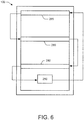
- Fig. 6 shows the arrangement of the evaporator coils 280 within the refrigeration system 240.
- the evaporator coils 280 may be arranged in series. Specifically, the refrigerant may flow from the compressor 250 to the condenser 260 and the expansion device and then to the evaporator coils 280. The refrigerant may flow from the top evaporator coil 285 and then downward through each evaporator coil 280 before returning to the refrigeration components.
- the refrigeration system 240 also may arrange the evaporator coils 280 in a parallel arrangement or otherwise. Other components and other configurations may be used herein.
- each shelf chamber 281 has an evaporator coil 280 on top and bottom thereof.
- Each shelf chamber 281 may be largely self-contained.
- each shelf assembly 230 may extend close to the door 140 such that only a small gap 282 may exist between the end of the shelf assembly 230 and the door 140.
- the gap 282 may be as small as about one millimeter or so.
- the size of the gap 282 may be varied by applying, for example, a pricing strip and the like at the end of the shelf assembly 230.
- the gap 282 may be small enough so as to implead significantly any airflow therethrough when the door 140 is closed. Other types of separation devices may be used herein.
- each shelf chamber 281 may have its own door. This arrangement also would prevent the loss of cold air from the other chambers 281. Other components and other configurations may be used herein.
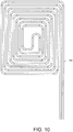
- Figs. 7-10 show an example of the shelf assembly 230.
- the shelf assembly 230 is shown as being rectangular, any shape including the hexagonal shape may be used herein.
- the shelf assembly 230 includes a top surface 290 and a bottom surface 300.
- the surfaces 290, 300 may be made out of thin metals and the like with good heat transfer characteristics.
- the front of the shelf assembly 230 may include the pricing strip or a header 310.
- the header 310 may have pricing, advertising and other types of indicia thereon.
- the shelf assembly 230 may be positioned within the product space 220 by a pair of rails 320 or other types of support elements and the like. Other components and other configurations may be used herein.
- the shelf assembly 230 includes one or more phase change material cells 330.
- the phase change material cells 330 are positioned on the top and the bottom of the evaporator coils 280 and within the surfaces 290, 300.
- the phase change material cells 330 may be made out of a somewhat flexible material so as to accommodate thermal expansion and contraction therein. Any number of the phase change material cells 330 may be used.
- the phase change material cells 330 may have any suitable size, shape, or configuration.
- the phase change material cells 330 include a phase change material 340 therein. Alternatively, the phase change material 340 may be positioned in a single cell or container.
- the phase change material 340 may be water, brine, a water and glycol mixture, and the like. The phase change material 340 may be selected based upon its freezing point.
- the freezing point of the phase change material 340 ensures that the products 10 do not fall below the freezing point and freeze themselves.
- the shelf assembly 230 has one or more layers of insulation 350 positioned about the phase change material cells 330.
- the shelf assembly 230 is held together by a number of spring loaded bolts 360.
- the spring loaded bolts 360 accommodate the thermal expansion and contraction of the phase change material cells 330.
- the phase change material cells 330 also may be an open structure foam material soaked with water or other type of phase change material 340 so as to reduce expansion during freezing.
- the overall thermal load on the refrigeration system 240 may be increased. With this increase, greater flexibility may be possible with the selection of the compressor 250 and other refrigeration components. Specifically, the compressor 250 need not be sized according to the size or load on the cooler 100. A larger compressor 250 may quickly freeze the phase change material 340 for steady state cycles that may have a short on time period and a long off time period for improved efficiency. The use of the larger compressor need not increase overall energy demands given the use of the phase change material 340, i.e., all of the power draw is absorbed by the coldness of the phase change material 340.
- the refrigeration system 240 operates when electrical power is available. Specifically, the evaporator coils 280 freeze the phase change material 340 in the phase change material cells 330 of the shelf assemblies 230. The shelf assemblies 230 thus chill the air in the air in each of the shelf chamber 281 via the frozen phase change material 340. The heat exchange between the air and the products 10 thus causes the products 10 to be chilled.
- the compressor 250 and the refrigeration system 240 may be turned off when the phase change material 340 has solidified.
- the chilled condition may be between about two to about six degrees Celsius with about four degrees Celsius or so preferred.
- the phase change material cells 330 may maintain the products 10 in a chilled condition for an extended period of time even when electrical power is lost.
- the phase change material 340 maintains the products 10 in a chilled condition as the phase change material 340 melts.
- the cooler 100 thus performs as an ice chest in the absence of electrical power.
- the phase change material 340 then may be refrozen by the refrigeration system 240 when the power is restored.
- About three to six hours of electrical power per day may be sufficient to maintain the products 10 within the cooler 100 in a chilled condition or at least close to the preferred temperature range for an extended period of time.
- each shelf chamber 281 acts as its own ice chest to avoid or limit heat stratification from top to bottom.
- each shelf chamber 281 has an evaporator coil 280 on the top and bottom thereof so as to cool the shelf chamber 281.
- the small gap 282 between each shelf assembly 230 and the door 140 thus prevents migration of warm air between the shelf chambers 281.
- the top shelf chamber 283 with the top evaporator coil 285 remains as cold as the lower shelf chambers 281 even when the power is off.
- Fig. 11 shows an example of a number of the products 10 loaded within the hexagon cooler 110 in a zig-zag product arrangement 370 of the bottles or cans, pouches, boxes, and the like.
- the overall efficiency of the hexagon cooler 110 may be based in part on parameters such as product density, i.e. , how tightly the products 10 may be packed therein, as well as the amount of leakage through the outer frame 120.
- Conventional coolers with a substantially square shape would have more overall surface area as compared to the hexagon shape. More surface area, however, generally leads to more heat transfer loses.
- the hexagon cooler 110 thus may have less overall surface area and particularly less inside surface area.
- Other factors influencing overall efficiency may include the size of the door 140, the nature of the gasket seal, and the nature of the insulation within the outer frame 120.
- the volume of the product space 220 thus may be sized and configured to maximize the number of products 10 that may be positioned on each of the shelf assemblies 230.
- the intended size and configuration may vary depending upon the size and shape of the intended products 10 to be positioned therein.
- the zig-zag product arrangement 370 shown in Fig. 11 provides good product density within the product space 220 and hence a good volume (number of products) to surface ratio.
- the use of the zig-zag product arrangement 370 within the hexagon cooler 110 thus may decrease the cooler load per product (watt-hour/product) for the hexagon cooler 110 as compared to a conventional square shaped cooler by about twenty percent (20%) or more. Such an increase in efficiency further reduces the overall energy needs of the hexagon cooler 110.
- such an improved product load also may increase the length of time that the products 10 within the cooler 100 may remain chilled in the absence of electrical power.
- Other types of bottle configurations also may be used herein.
- the hexagon cooler 110 may provide improved pull down or make cold capability as well as improved keep cold capability. Moreover, the refrigeration system 240 needs no type of air movement device within the product space 220 for a further increase in efficiency. Although a fan or other type of air movement device may aid in the overall pull down capability when power is available as well reducing temperature stratification.
- the hexagon cooler 110 thus provides the phase change material cells 330 for cooling in an overall configuration having less surface area but with improved product density for efficient long term operation even without reliable power.
- the change in shape provides a decreased overall cabinet load as well as a decreased load per bottle. Moreover, the change in shape accommodates the increase in load required to freeze the phase change material 340.
- a hexagonally shaped cooler with the zig-zag product configuration 370 or another product configuration may be used in conjunction with a conventional cooler refrigeration system.
- a refrigeration system may supply cold air to the product space 220, which may then be circulated within the product space 220 to chill the products contained therein.
- the shelves in such conventional refrigeration systems may be wire shelves or other shelves that promote the circulation of cool air in a desirable flow path.
- Other components and other configurations may be used herein.
- Figs. 12 and 13 show alternative embodiments of the cooler 110.
- the cooler 100 may be in the form of a D-shaped cooler 380.
- the D-shaped cooler 380 may include a flat front panel 390 with a door 400 or a number of doors 400 positioned thereon. A transparent panel also may be used herein.
- the D-shaped cooler 380 further may include a semi-circular outer frame 410.
- Fig. 12 shows the D-shaped cooler 380 with a number of the products 10 positioned therein in a uniform row and column configuration 420.
- Fig. 13 shows the products 10 within the D-shaped cooler 380 having the zig-zag product configuration 370 described above. Other types of product configurations may be used herein.
- Both D-shaped coolers 380 may have less overall surface area as compared to a conventional square shaped cooler. Given such, both D-shaped coolers 380 may provide an improved load per product of about fifteen percent (15%) or more even with the differing product configurations. Other components and other configurations may be used herein.
- the D-shaped cooler 380 or the other coolers described herein may include more than one door 400.
- each shelf within the D-shaped cooler 380 or other coolers may have a shelf door 385.
- Such a configuration may increase the capacity of the D-shaped cooler 380 to keep cold as only the contents of a single shelf may be exposed to ambient conditions.
- Any number of the doors 400 may be used herein in any size, shape, or configuration.
- Fig. 15 shows an example of a Seebeck indicator 430 for use with the cooler 100.
- the lighting inside a cooler 100 such as a glass door merchandiser, also goes off with the loss of electrical power.
- the lack of lighting may make the products 10 therein unappealing and/or give the impression that the products 10 are not in a chilled condition.
- the Seebeck indicator 430 may resolve this perception issue by using the Seebeck effect to light up one or more light emitting diodes or other type of lighting fixture based upon the temperature differential between the outer frame 120 and the product space 220.
- the Seebeck indicator 430 may use a Peltier element 440.
- the Peltier element 440 may have a hot side 450 in thermal communication with the outer frame 120 and a cold side 460 in thermal communication with the product space 220.
- the Peltier element 440 may be in a circuit with one or more light emitting diodes 470. Based upon the temperature difference across the Peltier element 440, the Peltier element 440 may generate sufficient voltage so as to operate the light emitting diodes 470.
- the temperature differential generally may be about at least twenty degrees Celsius or so. Different types of converters and control circuits may be used herein. Other components and other configurations may be used herein.
- the Seebeck indicator 430 thus provides a visual indication that the products 10 within the cooler 100 are in a chilled condition even if the electrical power to the cooler 100 is unavailable such that the cooler 100 is dark.
- the light emitting diodes 470 may illuminate a sign or other type of indicator outside the cooler 100 stating "COLD BEVERAGES INSIDE" and the like. Any type of messaging indicia may be used herein.
- the greater the temperature differential the greater the available power such that the brightness of the light emitting diodes 470 may vary with the temperature differential.
- the Peltier element 440 also may drive other types of loads so as to provide other types of indications. For example, audio indications may be used herein.
- Alternative power sources also may be used herein such as conventional batteries, super capacitors, and the like.
- Fig. 16 shows an example of an alternative embodiment of a cooler 500 which is not part of the present invention.
- the cooler 500 may include an ice based refrigeration system 510.
- known ice based systems generally provide for a block of ice to be installed at the top of the cooler so as to cool the contents of the cooler as the ice melts downward. Such a configuration, however, may mean that the cooler may be top heavy and/or require a significant footprint to remain stable.
- the cooler 500 may include an outer frame 520. Positioned within the outer frame 520 may be a number of payload containers 530. The products 10 and other items to be chilled may be placed therein.
- the ice based refrigeration system 510 also may include a reservoir 540. The reservoir 540 may surround each of the payload containers 530 so as to chill the contents therein.
- the ice based refrigeration system 510 may include an ice rest 550.
- the ice rest 550 may be positioned about a bottom portion 560 of the reservoir 540.
- the ice rest 550 may include a number of apertures and the like so as to allow water to melt from the ice rest 550 and into the bottom portion 560 of the reservoir 540.
- the water below the ice rest 550 may be at about four degrees Celsius or so and hence very dense.
- the ice based refrigeration system 510 also may include a heat exchange body 570.
- a first end 580 of the heat exchange body 510 may be in the bottom portion 560 of the reservoir 540 while a second end 590 may be in thermal communication with a top portion 565.
- the heat exchange body 570 may be well insulated between the first end 580 and the second end 590 with one or more layers of insulation 600. Other components and other configurations may be used herein.
- a block of ice 610 may be positioned on the ice rest 550.
- the ice 610 keeps the bottom portion 560 of the reservoir 540 cold.
- the block of ice 610 may be formed over evaporator coils of a refrigeration circuit (not shown).
- One or more ice probes may regulate the refrigeration circuit so as to turn on to build up the block of ice 610 or turn off once the block of ice has reached a predetermined size.
- the refrigeration circuit may be periodically operated so as to maintain a sufficiently large block of ice 610.
- the heat exchange body 570 then exchanges heat between the bottom portion 560 and the top portion 565 of the reservoir 540 so as to maintain each of the payload containers 530 in a chilled condition for an extended period of time.
- the cooler 500 may be substantially stable given the positioning of the block of ice 610 at the bottom thereof. Moreover, the cooler 500 may be taller given such stability. Specifically, the cooler 500 may be tall but somewhat shallow with a reduced footprint.
- the use of ice cubes or ice flakes may kick start and/or charge the ice based refrigeration system 510.
- a water, brine, water and glycol mixture, or other type of solution also may be used herein. Other components and other configurations may be used herein.
- Fig. 17 shows an example of an alternative embodiment of a cooler 620 which is also not part of the present invention.
- the cooler 620 may include an outer shell 630.
- the outer shell 630 may be in the form of a rectangle, a hexagon, a D-shape, or any suitable shape.
- the outer shell 630 may have a top door 640.
- a front door or other type of access may be provided. Any of the doors also may have a transparent panel and the like.
- the cooler 620 may include a product space 650 therein.
- the product space 650 may be in the shape of a hexagon. Other shapes may be used herein.
- the cooler 630 may be unpowered and without refrigeration components. Instead, the cooler 630 may use a number of replaceable phase change material packs 660 therein.
- one phase change material pack 660 may be mounted about the top door 640.
- a further phase change material pack 660 may be positioned about a bottom 670 of the product space 650.
- the phase change material pack 660 may be positioned within a slidable drawer 680 positioned about the bottom 670 of the product space 650. Any number of phase change material packs 660 may be used herein.
- the cooler 630 also may have shelves therein such that the phase change material packs 660 may be slid or positioned therein. Other components and other configurations may be used herein.
- the frozen replaceable phase change material packs 660 may be slid or otherwise positioned within the cooler 630.
- the phase change material packs 660 keep the products therein chilled for an extended period of time. Positioning the products in the zig-zag product configuration 370 within the hexagonally shaped product space 650 further serves to keep the products therein cold.
- the phase change material packs 660 may be replaced upon melting and refrozen elsewhere.
- the phase change material packs 660 also may be used in any of the other coolers described herein or otherwise to kick start the pull down process and the like.
Claims (13)
- Kühlaggregat (100), das Folgendes umfasst:einen äußeren Rahmen (120);einen Produktraum (220) innerhalb des äußeren Rahmens (120); undmehrere Ablageanordnungen (230), positioniert im Inneren des Produktraums (220);wobei die mehreren Ablageanordnungen (230) eine Verdampferrohrschlange (280, 285) und eine oder mehrere Phasenwechselmaterialzellen (330) mit einem Phasenwechselmaterial (340) darin umfassen;wobei die mehreren Ablageanordnungen (230) den Produktraum (220) in mehrere Ablagekammern (281) teilen, die jeweils die Verdampferrohrschlange (280, 285) und die eine oder mehreren Phasenwechselmaterialzellen (330) an der Oberseite und Unterseite davon aufweisen,wobei die mehreren Ablageanordnungen (230) eine obere Oberfläche (290) und eine untere Oberfläche (300) umfassen,wobei das Kühlaggregat dadurch gekennzeichnet ist, dass das Phasenwechselmaterial innerhalb der an der Oberseite und der Unterseite der Verdampferrohrschlange (280, 285) innerhalb der mehreren Ablageanordnungen zwischen der oberen Oberfläche (290) und der unteren Oberfläche (300) der mehreren Ablageanordnungen positionierten Phasenwechselmaterialzellen (330) angeordnet ist;wobei die mehreren Ablageanordnungen (230) eine oder mehrere Schichten von Isolation (350) umfassen, die um die Phasenwechselmaterialzellen (330) positioniert sind; undwobei die mehreren Ablageanordnungen (230) eine oder mehrere federbelastete Schrauben (360) umfassen, die zwischen der oberen Oberfläche (290) und der unteren Oberfläche (300) der mehreren Ablageanordnungen positioniert sind, wobei die eine oder mehreren federbelasteten Schrauben (290) dazu ausgelegt sind, thermische Ausdehnung und Zusammenziehung des Phasenwechselmaterials (330) aufzunehmen.
- Kühlaggregat nach Anspruch 1, wobei der äußere Rahmen (120) eine hexagonale Form umfasst.
- Kühlaggregat nach Anspruch 1 oder 2, wobei der äußere Rahmen (120) sechs oder mehr Seiten umfasst.
- Kühlaggregat nach einem der vorhergehenden Ansprüche, wobei der äußere Rahmen (120) eine Tür (140) mit einer transparenten Tafel (160) umfasst.
- Kühlaggregat nach einem der vorhergehenden Ansprüche, ferner umfassend ein Kühlsystem (240) in Kommunikation mit der Verdampferrohrschlange (280).
- Kühlaggregat nach einem der vorhergehenden Ansprüche, wobei das Phasenwechselmaterial (340) Wasser umfasst.
- Kühlaggregat nach einem der vorhergehenden Ansprüche, wobei die mehreren Ablageanordnungen (230) eine obere Ablageanordnung mit einer oberen Verdampferrohrschlange (285), positioniert um eine Oberseite des Produktraums, umfassen.
- Kühlaggregat nach einem der vorhergehenden Ansprüche, wobei die mehreren Ablagekammern (281) mehrere unabhängige Ablagekammern umfassen.
- Kühlaggregat nach einem der vorhergehenden Ansprüche, in Kombination mit mehreren Produkten (10), positioniert in einer Zick-Zack-Anordnung.
- Kühlaggregat nach einem der Ansprüche 1 bis 8, in Kombination mit mehreren Produkten (10), positioniert in einer gleichförmigen Reihen- und Spaltenanordnung.
- Kühlaggregat nach Anspruch 1 oder einem der Ansprüche 4 bis 10, wobei der äußere Rahmen (120) eine D-Form umfasst.
- Kühlaggregat nach einem der vorhergehenden Ansprüche, ferner umfassend einen Seebeck-Indikator (430), positioniert um den äußeren Rahmen (120) und den Produktraum (220).
- Verfahren zum Betreiben eines Kühlaggregats (100) mit intermittierendem Strom, das Folgendes umfasst:Positionieren einer Anzahl von Ablageanordnungen (230) im Inneren des Kühlaggregats,wobei die Ablageanordnungen (230) eine Verdampferrohrschlange (280, 285) und eine oder mehrere Phasenwechselmaterialzellen (330) mit einem Phasenwechselmaterial (340) darin umfassen,wobei die Ablageanordnungen (230) das Kühlaggregat in eine Anzahl von Ablagekammern (281) teilen, die jeweils die Verdampferrohrschlange (280, 285) und eine oder mehreren Phasenwechselzellen (330) an der Oberseite und Unterseite davon aufweisen,wobei die mehreren Ablageanordnungen (230) eine obere Oberfläche (290) und eine untere Oberfläche (300) umfassen,wobei das Verfahren dadurch gekennzeichnet ist, dass das Phasenwechselmaterial innerhalb der an der Oberseite und der Unterseite der Verdampferrohrschlange (280, 285) innerhalb der mehreren Ablageanordnungen zwischen der oberen Oberfläche (290) und der unteren Oberfläche (300) der mehreren Ablageanordnungen positionierten Phasenwechselmaterialzellen (330) angeordnet ist,wobei die mehreren Ablageanordnungen (230) eine oder mehrere Schichten von Isolation (350) umfassen, die um die Phasenwechselmaterialzellen (330) positioniert sind; undwobei die mehreren Ablageanordnungen (230) eine oder mehrere federbelastete Schrauben (360) umfassen, die zwischen der oberen Oberfläche (290) und der unteren Oberfläche (300) der mehreren Ablageanordnungen positioniert sind, wobei die eine oder mehreren federbelasteten Schrauben (360) dazu ausgelegt sind, thermische Ausdehnung und Zusammenziehung des Phasenwechselmaterials (330) aufzunehmen;Zirkulieren eines Kältemittels über das Phasenwechselmaterial, wenn der Strom eingeschaltet ist; Gefrieren des Phasenwechselmaterials; undHalten des Kühlaggregats in der gekühlten Bedingung für einen längeren Zeitraum, wenn der Strom ausgeschaltet ist, durch Schmelzen des Phasenwechselmaterials.
Applications Claiming Priority (2)
| Application Number | Priority Date | Filing Date | Title |
|---|---|---|---|
| US201361919904P | 2013-12-23 | 2013-12-23 | |
| PCT/US2014/071067 WO2015100119A1 (en) | 2013-12-23 | 2014-12-18 | Intermittent power grid ready cooler |
Publications (3)
| Publication Number | Publication Date |
|---|---|
| EP3087332A1 EP3087332A1 (de) | 2016-11-02 |
| EP3087332A4 EP3087332A4 (de) | 2017-08-02 |
| EP3087332B1 true EP3087332B1 (de) | 2021-03-24 |
Family
ID=53479566
Family Applications (1)
| Application Number | Title | Priority Date | Filing Date |
|---|---|---|---|
| EP14874552.4A Active EP3087332B1 (de) | 2013-12-23 | 2014-12-18 | Kühlaggregat mit intermittierendem stromnetz |
Country Status (3)
| Country | Link |
|---|---|
| US (1) | US10156395B2 (de) |
| EP (1) | EP3087332B1 (de) |
| WO (1) | WO2015100119A1 (de) |
Families Citing this family (5)
| Publication number | Priority date | Publication date | Assignee | Title |
|---|---|---|---|---|
| DE102017000237A1 (de) | 2016-03-16 | 2017-09-21 | Liebherr-Hausgeräte Lienz Gmbh | Kältemittelkreislauf für ein Kühl- und/oder Gefriergerät |
| US10278895B2 (en) * | 2016-04-11 | 2019-05-07 | Tokitae Llc | Portable device for cold chain storage |
| US10188223B2 (en) * | 2016-09-26 | 2019-01-29 | Hussmann Corporation | Refrigerated merchandiser including eutectic plate refrigeration |
| US20220178606A1 (en) * | 2019-03-22 | 2022-06-09 | Lg Electronics Inc. | Refrigerator |
| CN112577227A (zh) * | 2019-09-27 | 2021-03-30 | 开利公司 | 集装设备和物品存放运输方法 |
Citations (2)
| Publication number | Priority date | Publication date | Assignee | Title |
|---|---|---|---|---|
| EP0098052A2 (de) * | 1982-06-26 | 1984-01-11 | THORN EMI Domestic Appliances Limited | Gefriereinrichtungen |
| WO1994005959A1 (en) * | 1992-09-01 | 1994-03-17 | Allan John Cassell | Refrigerator and freezer units |
Family Cites Families (17)
| Publication number | Priority date | Publication date | Assignee | Title |
|---|---|---|---|---|
| US1883961A (en) * | 1931-11-16 | 1932-10-25 | Kosmerl Josiph | Portable refrigerator |
| US2418062A (en) * | 1944-07-29 | 1947-03-25 | Abrahamson William | Refrigerated display cabinet |
| US4002384A (en) * | 1975-09-04 | 1977-01-11 | General Motors Corporation | Compact refrigerator combined with top storage container |
| JPS623659Y2 (de) * | 1981-01-19 | 1987-01-27 | ||
| US4580412A (en) * | 1981-10-13 | 1986-04-08 | Wells Raymond R | Portable refrigerated unit |
| US5505046A (en) * | 1994-01-12 | 1996-04-09 | Marlow Industrie, Inc. | Control system for thermoelectric refrigerator |
| IT1316359B1 (it) * | 2000-02-11 | 2003-04-10 | Candy Spa | Apparecchio frigorifero con griglia refrigerante provvista di piastreeutettiche |
| US6883929B2 (en) * | 2001-04-04 | 2005-04-26 | Color Kinetics, Inc. | Indication systems and methods |
| DE20312620U1 (de) * | 2003-08-14 | 2003-10-09 | Bsh Bosch Siemens Hausgeraete | Kältegerät mit Türsicherung |
| US7797950B2 (en) | 2006-07-19 | 2010-09-21 | Neal Energy Management Llc | Active thermal insulation system utilizing phase change material and a cool air source |
| WO2009053769A1 (es) * | 2007-10-25 | 2009-04-30 | Rok Internacional, S.A. De C.V. | Refrigerador exhibidor con arreglo radial multi-charola |
| BRPI0822204A2 (pt) * | 2008-02-22 | 2015-06-23 | Imbera Sa De C V | Sistema melhorado de iluminação de gabinetes de refrigeração usando lâmpadas de led |
| US20110036744A1 (en) * | 2009-08-11 | 2011-02-17 | Abraham Joshua Heschel School | Decorative serving tray with freezable inserts |
| US8925338B2 (en) * | 2010-04-01 | 2015-01-06 | The Coca-Cola Company | Chest cooler |
| KR101123497B1 (ko) * | 2010-06-14 | 2012-03-23 | 윤동한 | 열전대를 이용한 매립형 광소자 패키지 모듈 |
| US20120291469A1 (en) * | 2011-05-17 | 2012-11-22 | General Electric Company | Refrigerator temperature control method and apparatus |
| US20150297000A1 (en) * | 2014-04-22 | 2015-10-22 | Heatcraft Refrigeration Products Llc | Refrigerated Display Case with Temperature Controlled Shelves |
-
2014
- 2014-12-18 WO PCT/US2014/071067 patent/WO2015100119A1/en active Application Filing
- 2014-12-18 US US15/104,471 patent/US10156395B2/en active Active
- 2014-12-18 EP EP14874552.4A patent/EP3087332B1/de active Active
Patent Citations (2)
| Publication number | Priority date | Publication date | Assignee | Title |
|---|---|---|---|---|
| EP0098052A2 (de) * | 1982-06-26 | 1984-01-11 | THORN EMI Domestic Appliances Limited | Gefriereinrichtungen |
| WO1994005959A1 (en) * | 1992-09-01 | 1994-03-17 | Allan John Cassell | Refrigerator and freezer units |
Also Published As
| Publication number | Publication date |
|---|---|
| EP3087332A4 (de) | 2017-08-02 |
| US10156395B2 (en) | 2018-12-18 |
| EP3087332A1 (de) | 2016-11-02 |
| US20160313046A1 (en) | 2016-10-27 |
| WO2015100119A1 (en) | 2015-07-02 |
Similar Documents
| Publication | Publication Date | Title |
|---|---|---|
| EP3087332B1 (de) | Kühlaggregat mit intermittierendem stromnetz | |
| US20090158768A1 (en) | Temperature controlled devices | |
| KR101389531B1 (ko) | 열전소자가 적용된 농식품 수배송 장치 | |
| US20140174100A1 (en) | Refrigerator with no-frost freezer | |
| RU2465523C2 (ru) | Холодильный аппарат и способ поддержания постоянной заданной температуры в холодильной камере холодильного аппарата | |
| KR20080053373A (ko) | 다기능으로 작동할 수 있는 냉장 시스템 | |
| EP1236960A1 (de) | Aufbewahrungsgerät, insbesondere für verderbliche Waren bei einer vorgewählten Temperatur | |
| KR20150051074A (ko) | 농식품 수배송 장치 | |
| CN103210427A (zh) | 自动售货机的冷却装置 | |
| CN102419043B (zh) | 蓄冷组件、抽屉组件和冰箱 | |
| CN202163741U (zh) | 新型蓄冷箱 | |
| RU2680453C2 (ru) | Теплоизолированный сосуд | |
| KR101295619B1 (ko) | 열전소자를 이용한 저장 용기 내부의 공기 순환 방법 | |
| KR200320682Y1 (ko) | 축냉식 냉장고 선반 및 이를 이용한 휴대용 아이스박스 | |
| EP2751504B1 (de) | Kühlelement für einen kühlschrank | |
| EP2092861B1 (de) | Verkaufsmöbel | |
| ES2252142T3 (es) | Electrodomestico frigorifico con rejilla de refrigeracion provista de placas eutecticas. | |
| KR101667660B1 (ko) | 냉장고용 축냉장치 | |
| JP2011038686A (ja) | 冷蔵庫 | |
| CN105513208A (zh) | 自动贩售机 | |
| US20140150468A1 (en) | Modular cooling and low energy ice | |
| US5403609A (en) | Method and equipment for storing foodstuffs, plants, vegetables, meats and other organic substances | |
| KR101280576B1 (ko) | 냉동식품용 쇼 케이스 | |
| CN202470571U (zh) | 蓄冷组件、抽屉组件和冰箱 | |
| CN204178455U (zh) | 自动贩售机 |
Legal Events
| Date | Code | Title | Description |
|---|---|---|---|
| PUAI | Public reference made under article 153(3) epc to a published international application that has entered the european phase |
Free format text: ORIGINAL CODE: 0009012 |
|
| 17P | Request for examination filed |
Effective date: 20160706 |
|
| AK | Designated contracting states |
Kind code of ref document: A1 Designated state(s): AL AT BE BG CH CY CZ DE DK EE ES FI FR GB GR HR HU IE IS IT LI LT LU LV MC MK MT NL NO PL PT RO RS SE SI SK SM TR |
|
| AX | Request for extension of the european patent |
Extension state: BA ME |
|
| DAX | Request for extension of the european patent (deleted) | ||
| A4 | Supplementary search report drawn up and despatched |
Effective date: 20170705 |
|
| RIC1 | Information provided on ipc code assigned before grant |
Ipc: A47F 3/04 20060101ALI20170629BHEP Ipc: F25D 25/02 20060101AFI20170629BHEP Ipc: F25D 11/00 20060101ALI20170629BHEP Ipc: F25D 16/00 20060101ALI20170629BHEP Ipc: F25B 39/02 20060101ALI20170629BHEP Ipc: F25B 5/04 20060101ALI20170629BHEP Ipc: F25D 27/00 20060101ALI20170629BHEP |
|
| STAA | Information on the status of an ep patent application or granted ep patent |
Free format text: STATUS: EXAMINATION IS IN PROGRESS |
|
| 17Q | First examination report despatched |
Effective date: 20191211 |
|
| GRAP | Despatch of communication of intention to grant a patent |
Free format text: ORIGINAL CODE: EPIDOSNIGR1 |
|
| STAA | Information on the status of an ep patent application or granted ep patent |
Free format text: STATUS: GRANT OF PATENT IS INTENDED |
|
| INTG | Intention to grant announced |
Effective date: 20201102 |
|
| GRAS | Grant fee paid |
Free format text: ORIGINAL CODE: EPIDOSNIGR3 |
|
| GRAA | (expected) grant |
Free format text: ORIGINAL CODE: 0009210 |
|
| STAA | Information on the status of an ep patent application or granted ep patent |
Free format text: STATUS: THE PATENT HAS BEEN GRANTED |
|
| AK | Designated contracting states |
Kind code of ref document: B1 Designated state(s): AL AT BE BG CH CY CZ DE DK EE ES FI FR GB GR HR HU IE IS IT LI LT LU LV MC MK MT NL NO PL PT RO RS SE SI SK SM TR |
|
| REG | Reference to a national code |
Ref country code: GB Ref legal event code: FG4D |
|
| REG | Reference to a national code |
Ref country code: CH Ref legal event code: EP |
|
| REG | Reference to a national code |
Ref country code: IE Ref legal event code: FG4D |
|
| REG | Reference to a national code |
Ref country code: AT Ref legal event code: REF Ref document number: 1374890 Country of ref document: AT Kind code of ref document: T Effective date: 20210415 Ref country code: DE Ref legal event code: R096 Ref document number: 602014076038 Country of ref document: DE |
|
| REG | Reference to a national code |
Ref country code: LT Ref legal event code: MG9D |
|
| PG25 | Lapsed in a contracting state [announced via postgrant information from national office to epo] |
Ref country code: GR Free format text: LAPSE BECAUSE OF FAILURE TO SUBMIT A TRANSLATION OF THE DESCRIPTION OR TO PAY THE FEE WITHIN THE PRESCRIBED TIME-LIMIT Effective date: 20210625 Ref country code: FI Free format text: LAPSE BECAUSE OF FAILURE TO SUBMIT A TRANSLATION OF THE DESCRIPTION OR TO PAY THE FEE WITHIN THE PRESCRIBED TIME-LIMIT Effective date: 20210324 Ref country code: HR Free format text: LAPSE BECAUSE OF FAILURE TO SUBMIT A TRANSLATION OF THE DESCRIPTION OR TO PAY THE FEE WITHIN THE PRESCRIBED TIME-LIMIT Effective date: 20210324 Ref country code: BG Free format text: LAPSE BECAUSE OF FAILURE TO SUBMIT A TRANSLATION OF THE DESCRIPTION OR TO PAY THE FEE WITHIN THE PRESCRIBED TIME-LIMIT Effective date: 20210624 Ref country code: NO Free format text: LAPSE BECAUSE OF FAILURE TO SUBMIT A TRANSLATION OF THE DESCRIPTION OR TO PAY THE FEE WITHIN THE PRESCRIBED TIME-LIMIT Effective date: 20210624 |
|
| PG25 | Lapsed in a contracting state [announced via postgrant information from national office to epo] |
Ref country code: SE Free format text: LAPSE BECAUSE OF FAILURE TO SUBMIT A TRANSLATION OF THE DESCRIPTION OR TO PAY THE FEE WITHIN THE PRESCRIBED TIME-LIMIT Effective date: 20210324 Ref country code: LV Free format text: LAPSE BECAUSE OF FAILURE TO SUBMIT A TRANSLATION OF THE DESCRIPTION OR TO PAY THE FEE WITHIN THE PRESCRIBED TIME-LIMIT Effective date: 20210324 Ref country code: RS Free format text: LAPSE BECAUSE OF FAILURE TO SUBMIT A TRANSLATION OF THE DESCRIPTION OR TO PAY THE FEE WITHIN THE PRESCRIBED TIME-LIMIT Effective date: 20210324 |
|
| REG | Reference to a national code |
Ref country code: NL Ref legal event code: MP Effective date: 20210324 |
|
| REG | Reference to a national code |
Ref country code: AT Ref legal event code: MK05 Ref document number: 1374890 Country of ref document: AT Kind code of ref document: T Effective date: 20210324 |
|
| PG25 | Lapsed in a contracting state [announced via postgrant information from national office to epo] |
Ref country code: NL Free format text: LAPSE BECAUSE OF FAILURE TO SUBMIT A TRANSLATION OF THE DESCRIPTION OR TO PAY THE FEE WITHIN THE PRESCRIBED TIME-LIMIT Effective date: 20210324 |
|
| PG25 | Lapsed in a contracting state [announced via postgrant information from national office to epo] |
Ref country code: SM Free format text: LAPSE BECAUSE OF FAILURE TO SUBMIT A TRANSLATION OF THE DESCRIPTION OR TO PAY THE FEE WITHIN THE PRESCRIBED TIME-LIMIT Effective date: 20210324 Ref country code: LT Free format text: LAPSE BECAUSE OF FAILURE TO SUBMIT A TRANSLATION OF THE DESCRIPTION OR TO PAY THE FEE WITHIN THE PRESCRIBED TIME-LIMIT Effective date: 20210324 Ref country code: CZ Free format text: LAPSE BECAUSE OF FAILURE TO SUBMIT A TRANSLATION OF THE DESCRIPTION OR TO PAY THE FEE WITHIN THE PRESCRIBED TIME-LIMIT Effective date: 20210324 Ref country code: EE Free format text: LAPSE BECAUSE OF FAILURE TO SUBMIT A TRANSLATION OF THE DESCRIPTION OR TO PAY THE FEE WITHIN THE PRESCRIBED TIME-LIMIT Effective date: 20210324 Ref country code: AT Free format text: LAPSE BECAUSE OF FAILURE TO SUBMIT A TRANSLATION OF THE DESCRIPTION OR TO PAY THE FEE WITHIN THE PRESCRIBED TIME-LIMIT Effective date: 20210324 |
|
| PG25 | Lapsed in a contracting state [announced via postgrant information from national office to epo] |
Ref country code: IS Free format text: LAPSE BECAUSE OF FAILURE TO SUBMIT A TRANSLATION OF THE DESCRIPTION OR TO PAY THE FEE WITHIN THE PRESCRIBED TIME-LIMIT Effective date: 20210724 Ref country code: SK Free format text: LAPSE BECAUSE OF FAILURE TO SUBMIT A TRANSLATION OF THE DESCRIPTION OR TO PAY THE FEE WITHIN THE PRESCRIBED TIME-LIMIT Effective date: 20210324 Ref country code: RO Free format text: LAPSE BECAUSE OF FAILURE TO SUBMIT A TRANSLATION OF THE DESCRIPTION OR TO PAY THE FEE WITHIN THE PRESCRIBED TIME-LIMIT Effective date: 20210324 Ref country code: PT Free format text: LAPSE BECAUSE OF FAILURE TO SUBMIT A TRANSLATION OF THE DESCRIPTION OR TO PAY THE FEE WITHIN THE PRESCRIBED TIME-LIMIT Effective date: 20210726 Ref country code: PL Free format text: LAPSE BECAUSE OF FAILURE TO SUBMIT A TRANSLATION OF THE DESCRIPTION OR TO PAY THE FEE WITHIN THE PRESCRIBED TIME-LIMIT Effective date: 20210324 Ref country code: ES Free format text: LAPSE BECAUSE OF FAILURE TO SUBMIT A TRANSLATION OF THE DESCRIPTION OR TO PAY THE FEE WITHIN THE PRESCRIBED TIME-LIMIT Effective date: 20210324 |
|
| REG | Reference to a national code |
Ref country code: DE Ref legal event code: R097 Ref document number: 602014076038 Country of ref document: DE |
|
| PG25 | Lapsed in a contracting state [announced via postgrant information from national office to epo] |
Ref country code: AL Free format text: LAPSE BECAUSE OF FAILURE TO SUBMIT A TRANSLATION OF THE DESCRIPTION OR TO PAY THE FEE WITHIN THE PRESCRIBED TIME-LIMIT Effective date: 20210324 Ref country code: DK Free format text: LAPSE BECAUSE OF FAILURE TO SUBMIT A TRANSLATION OF THE DESCRIPTION OR TO PAY THE FEE WITHIN THE PRESCRIBED TIME-LIMIT Effective date: 20210324 |
|
| PLBE | No opposition filed within time limit |
Free format text: ORIGINAL CODE: 0009261 |
|
| STAA | Information on the status of an ep patent application or granted ep patent |
Free format text: STATUS: NO OPPOSITION FILED WITHIN TIME LIMIT |
|
| PG25 | Lapsed in a contracting state [announced via postgrant information from national office to epo] |
Ref country code: SI Free format text: LAPSE BECAUSE OF FAILURE TO SUBMIT A TRANSLATION OF THE DESCRIPTION OR TO PAY THE FEE WITHIN THE PRESCRIBED TIME-LIMIT Effective date: 20210324 |
|
| 26N | No opposition filed |
Effective date: 20220104 |
|
| PG25 | Lapsed in a contracting state [announced via postgrant information from national office to epo] |
Ref country code: IS Free format text: LAPSE BECAUSE OF FAILURE TO SUBMIT A TRANSLATION OF THE DESCRIPTION OR TO PAY THE FEE WITHIN THE PRESCRIBED TIME-LIMIT Effective date: 20210724 |
|
| PG25 | Lapsed in a contracting state [announced via postgrant information from national office to epo] |
Ref country code: MC Free format text: LAPSE BECAUSE OF FAILURE TO SUBMIT A TRANSLATION OF THE DESCRIPTION OR TO PAY THE FEE WITHIN THE PRESCRIBED TIME-LIMIT Effective date: 20210324 |
|
| REG | Reference to a national code |
Ref country code: CH Ref legal event code: PL |
|
| REG | Reference to a national code |
Ref country code: BE Ref legal event code: MM Effective date: 20211231 |
|
| PG25 | Lapsed in a contracting state [announced via postgrant information from national office to epo] |
Ref country code: LU Free format text: LAPSE BECAUSE OF NON-PAYMENT OF DUE FEES Effective date: 20211218 Ref country code: IE Free format text: LAPSE BECAUSE OF NON-PAYMENT OF DUE FEES Effective date: 20211218 |
|
| PG25 | Lapsed in a contracting state [announced via postgrant information from national office to epo] |
Ref country code: BE Free format text: LAPSE BECAUSE OF NON-PAYMENT OF DUE FEES Effective date: 20211231 |
|
| PG25 | Lapsed in a contracting state [announced via postgrant information from national office to epo] |
Ref country code: LI Free format text: LAPSE BECAUSE OF NON-PAYMENT OF DUE FEES Effective date: 20211231 Ref country code: CH Free format text: LAPSE BECAUSE OF NON-PAYMENT OF DUE FEES Effective date: 20211231 |
|
| PG25 | Lapsed in a contracting state [announced via postgrant information from national office to epo] |
Ref country code: IT Free format text: LAPSE BECAUSE OF FAILURE TO SUBMIT A TRANSLATION OF THE DESCRIPTION OR TO PAY THE FEE WITHIN THE PRESCRIBED TIME-LIMIT Effective date: 20210324 |
|
| PG25 | Lapsed in a contracting state [announced via postgrant information from national office to epo] |
Ref country code: HU Free format text: LAPSE BECAUSE OF FAILURE TO SUBMIT A TRANSLATION OF THE DESCRIPTION OR TO PAY THE FEE WITHIN THE PRESCRIBED TIME-LIMIT; INVALID AB INITIO Effective date: 20141218 |
|
| PG25 | Lapsed in a contracting state [announced via postgrant information from national office to epo] |
Ref country code: CY Free format text: LAPSE BECAUSE OF FAILURE TO SUBMIT A TRANSLATION OF THE DESCRIPTION OR TO PAY THE FEE WITHIN THE PRESCRIBED TIME-LIMIT Effective date: 20210324 |
|
| PGFP | Annual fee paid to national office [announced via postgrant information from national office to epo] |
Ref country code: GB Payment date: 20231121 Year of fee payment: 10 |
|
| PGFP | Annual fee paid to national office [announced via postgrant information from national office to epo] |
Ref country code: FR Payment date: 20231122 Year of fee payment: 10 Ref country code: DE Payment date: 20231121 Year of fee payment: 10 |
|
| PG25 | Lapsed in a contracting state [announced via postgrant information from national office to epo] |
Ref country code: MK Free format text: LAPSE BECAUSE OF FAILURE TO SUBMIT A TRANSLATION OF THE DESCRIPTION OR TO PAY THE FEE WITHIN THE PRESCRIBED TIME-LIMIT Effective date: 20210324 |