EP3085437B1 - System und verfahren zur abgabe von fluiden, insbesondere farbigen fluiden - Google Patents
System und verfahren zur abgabe von fluiden, insbesondere farbigen fluiden Download PDFInfo
- Publication number
- EP3085437B1 EP3085437B1 EP16166016.2A EP16166016A EP3085437B1 EP 3085437 B1 EP3085437 B1 EP 3085437B1 EP 16166016 A EP16166016 A EP 16166016A EP 3085437 B1 EP3085437 B1 EP 3085437B1
- Authority
- EP
- European Patent Office
- Prior art keywords
- dosage
- delivery
- station
- fluid
- magazine
- Prior art date
- Legal status (The legal status is an assumption and is not a legal conclusion. Google has not performed a legal analysis and makes no representation as to the accuracy of the status listed.)
- Not-in-force
Links
- 239000012530 fluid Substances 0.000 title claims description 117
- 238000000034 method Methods 0.000 title claims description 66
- 230000008569 process Effects 0.000 claims description 40
- 239000000203 mixture Substances 0.000 claims description 26
- 238000005406 washing Methods 0.000 claims description 15
- 230000008878 coupling Effects 0.000 claims description 6
- 238000010168 coupling process Methods 0.000 claims description 6
- 238000005859 coupling reaction Methods 0.000 claims description 6
- 238000004590 computer program Methods 0.000 claims description 2
- 239000000047 product Substances 0.000 description 12
- 238000004519 manufacturing process Methods 0.000 description 8
- 230000008901 benefit Effects 0.000 description 4
- 239000002904 solvent Substances 0.000 description 4
- 230000001052 transient effect Effects 0.000 description 3
- XLYOFNOQVPJJNP-UHFFFAOYSA-N water Substances O XLYOFNOQVPJJNP-UHFFFAOYSA-N 0.000 description 3
- 230000008859 change Effects 0.000 description 2
- 238000010981 drying operation Methods 0.000 description 2
- 239000000976 ink Substances 0.000 description 2
- 238000009825 accumulation Methods 0.000 description 1
- 150000001875 compounds Chemical class 0.000 description 1
- 238000004880 explosion Methods 0.000 description 1
- 239000012467 final product Substances 0.000 description 1
- 230000006870 function Effects 0.000 description 1
- 239000007788 liquid Substances 0.000 description 1
- 238000012544 monitoring process Methods 0.000 description 1
- 239000003973 paint Substances 0.000 description 1
- 230000032258 transport Effects 0.000 description 1
Images


Classifications
-
- B—PERFORMING OPERATIONS; TRANSPORTING
- B01—PHYSICAL OR CHEMICAL PROCESSES OR APPARATUS IN GENERAL
- B01F—MIXING, e.g. DISSOLVING, EMULSIFYING OR DISPERSING
- B01F33/00—Other mixers; Mixing plants; Combinations of mixers
- B01F33/80—Mixing plants; Combinations of mixers
- B01F33/84—Mixing plants with mixing receptacles receiving material dispensed from several component receptacles, e.g. paint tins
- B01F33/846—Mixing plants with mixing receptacles receiving material dispensed from several component receptacles, e.g. paint tins using stored recipes for determining the composition of the mixture to be produced, i.e. for determining the amounts of the basic components to be dispensed from the component receptacles
-
- B—PERFORMING OPERATIONS; TRANSPORTING
- B01—PHYSICAL OR CHEMICAL PROCESSES OR APPARATUS IN GENERAL
- B01F—MIXING, e.g. DISSOLVING, EMULSIFYING OR DISPERSING
- B01F33/00—Other mixers; Mixing plants; Combinations of mixers
- B01F33/80—Mixing plants; Combinations of mixers
- B01F33/85—Mixing plants with mixing receptacles or mixing tools that can be indexed into different working positions
-
- B—PERFORMING OPERATIONS; TRANSPORTING
- B01—PHYSICAL OR CHEMICAL PROCESSES OR APPARATUS IN GENERAL
- B01F—MIXING, e.g. DISSOLVING, EMULSIFYING OR DISPERSING
- B01F35/00—Accessories for mixers; Auxiliary operations or auxiliary devices; Parts or details of general application
- B01F35/10—Maintenance of mixers
- B01F35/145—Washing or cleaning mixers not provided for in other groups in this subclass; Inhibiting build-up of material on machine parts using other means
-
- B—PERFORMING OPERATIONS; TRANSPORTING
- B01—PHYSICAL OR CHEMICAL PROCESSES OR APPARATUS IN GENERAL
- B01F—MIXING, e.g. DISSOLVING, EMULSIFYING OR DISPERSING
- B01F35/00—Accessories for mixers; Auxiliary operations or auxiliary devices; Parts or details of general application
- B01F35/71—Feed mechanisms
- B01F35/715—Feeding the components in several steps, e.g. successive steps
-
- B—PERFORMING OPERATIONS; TRANSPORTING
- B01—PHYSICAL OR CHEMICAL PROCESSES OR APPARATUS IN GENERAL
- B01F—MIXING, e.g. DISSOLVING, EMULSIFYING OR DISPERSING
- B01F35/00—Accessories for mixers; Auxiliary operations or auxiliary devices; Parts or details of general application
- B01F35/80—Forming a predetermined ratio of the substances to be mixed
- B01F35/88—Forming a predetermined ratio of the substances to be mixed by feeding the materials batchwise
- B01F35/881—Forming a predetermined ratio of the substances to be mixed by feeding the materials batchwise by weighing, e.g. with automatic discharge
-
- B—PERFORMING OPERATIONS; TRANSPORTING
- B01—PHYSICAL OR CHEMICAL PROCESSES OR APPARATUS IN GENERAL
- B01F—MIXING, e.g. DISSOLVING, EMULSIFYING OR DISPERSING
- B01F2101/00—Mixing characterised by the nature of the mixed materials or by the application field
- B01F2101/30—Mixing paints or paint ingredients, e.g. pigments, dyes, colours, lacquers or enamel
Definitions
- the present invention relates to a system and a method for delivery of fluids, in particular coloured fluids, solvents, water-based paints, inks, etc.
- document US4827993A relates to an automatic system for carrying a reservoir and metering liquid from the reservoir.
- Said document discloses a system according to the preamble of claim 1.
- Current fluid dosage systems make use of integrated dosage machines for correctly dosing the fluids in order to implement a final formula.
- a final formula is meant to be a compound obtained by means of a single fluid or a mixture of at least two fluids.
- Current integrated dosage machines comprise a fluid accumulation assembly, a dosage head, and a scale for dosing the components, i.e. the single fluids, in a sequential manner and for moving the containers in order to remove the final product.
- a system for delivery of fluids in particular coloured fluids, is described herein, which is adapted to implement a dosage process wherein containers are filled up in order to obtain a finished product according to a given formula, said formula being representative of the dosage and/or composition of one or more fluids.
- the system according to the invention comprises the features of claim 1.
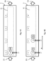
- FIG. 1 and 2 there is schematically shown a system 1 for delivery of fluids according to the present invention.
- Fig. 1 and Fig. 2 show a schematic top view of the system 1.
- the system 1 comprises a dosage line 3 and at least one magazine 5,7.
- a first magazine 5 is arranged along a first side of the dosage line 3
- a second magazine 7 is arranged along a second side of the dosage line 3.
- the dosage line 3 comprises motion means 31, e.g. an automatic conveyor, adapted to move, in the sense and direction of an arrow A, containers B 1 , B 2 , B 3 ,..., B n on support means of the dosage line 3, e.g. a roller track.
- the dosage line 3 comprises P stations S 1 , S 2 , S 3 ,..., S p , wherein at each p-th station S an n-th container B and an i-th delivery actuator E (E 1 , E 2 , E 3 ,..., E i ) can be placed, the latter being arranged in proximity to an opening of an n-th container B.
- Said i-th delivery actuator E allows delivering the fluid into the n-th container B.
- the first magazine 5 and the second magazine 7 comprise delivery valves V 1 , V 2 , V 3 ,..., V m , wherein a storage point D 1 , D 2 , D 3 ,..., D m corresponds to each one of them.
- Each delivery valve V 1 , V 2 , V 3 ,..., V m can be connected, through fluid transportation means, to a tank containing a certain fluid, in particular a coloured fluid. More in detail, the fluid transportation means comprise a delivery pump connected to the tank, and a tube with one end connected to the delivery pump; the other end of the tube is connected to the delivery valve V m . It is clear that the fluid transportation means may comprise technical elements that are alternative to the above-mentioned ones.
- the dosage line 3 comprises washing modules L 1 , L 2 , L 3 ,..., L j , each one of which is arranged in proximity to the dosage point. Furthermore, at every station S there is a scale that measures and determines the weight of the container B; this is useful for determining the quantity of fluid delivered into the containers B when the latter are being filled with a fluid.
- each station S there is one container B, one delivery actuator E, one scale, and, preferably, one washing module L.
- the function of the washing module L is to wash, and possibly also dry, the delivery valves V once the dosage process has been completed.
- the term "dosage process” refers herein to an operating process during which the containers B are filled in order to obtain a finished product for each formula.
- the system 1 further comprises a robot 9, in particular a robotic arm, which is free to move forwards and backwards in a longitudinal direction (reference arrow RO) and in a transversal direction (reference arrow RV) of the dosage line 3.
- the robot 9 is therefore adapted to pick up a delivery valve V 1 , V 2 , V 3 ,..., V m from a storage point D 1 , D 2 , D 3 ,..., D m and place it at a dosage point of the dosage line 3, i.e. on a delivery actuator E 1 , E 2 , E 3 ,..., E i in proximity to an opening of a corresponding container B 1 , B 2 , B 3 ,..., B n .
- the system 1 comprises a control unit 11 configured for controlling and monitoring the operation and effectiveness of the whole system 1. More in detail, the control unit 11 comprises at least one processor and memory means (not shown in the drawings), which can execute machine instructions for checking and controlling the system 1.
- the control unit 11 is connected to the first magazine 5, the dosage line 3, the second magazine 7, and the robot 9; therefore, the control unit 11 can exchange data with said elements 3, 5, 7 and 9.
- control unit 11 controls PLC ("Programmable Logic Controller") modules included in the dosage line 3, in the first magazine 5, and in the second magazine 7.
- PLC Programmable Logic Controller
- a first container B 1 is positioned on the support means of the dosage line 3 while passing through and entry area 13 of the dosage line 3.
- the first container B 1 is de facto positioned at a first station S 1 , where there are a first delivery actuator E 1 and a first washing module L 1 , as well as a first scale.
- a robot 9 picks up, at a storage point D 1 , a first delivery valve V 1 associated with a first coloured fluid 17, and moves it towards the first delivery actuator E 1 , which will allow it to open, so that the first coloured fluid 17 will be delivered into the first container B 1 .
- the first scale While the first coloured fluid 17 is being delivered, the first scale continuously checks the weight of the first container B 1 , until it reaches a limit value dictated by the formula, e.g. 10% of the whole composition. When the first scale detects such limit value, the first delivery actuator E 1 will command the first delivery valve V 1 to close. At the end of step 1, the first container B 1 will thus only contain the first coloured fluid 17.
- a limit value dictated by the formula e.g. 10% of the whole composition.
- the motion means allow the first container B 1 to translate or advance towards the second station S 2 (in the direction of the arrow A) and, preferably at the same time, a second container B 2 is positioned, from the entry area 13, onto the first station S 1 . It is worth specifying that it is the control unit 11 that controls the motion means for moving the containers B n from a first station to a second station when the fluid reaches the limit value dictated by said formula.
- the first delivery actuator E 1 commands the first delivery valve V 1 to open, thereby allowing the first coloured fluid 17 to be delivered into the second container B 2 .
- the robot 9 picks up, from a storage point D 2 , a second delivery valve V 2 associated with a second coloured fluid 19, and moves it towards the second delivery actuator E 2 , which will allow it to open, so that the second coloured fluid 19 will be delivered into the first container B 1 .
- a second scale checks the weight of the first container B 1 until it reaches a limit value dictated by the formula, e.g. 30% of the whole composition (in other words, the second coloured fluid 19 is delivered in a quantity equal to 20% of the entire composition).
- the second delivery actuator E 2 will command the second delivery valve V 2 to close; likewise, the first delivery valve V 1 will be closed at the first station S 1 for the first coloured fluid 17, which will have been delivered up to a limit value of 10% of the whole composition.
- the first container B 1 will contain 10% of the first coloured fluid 17 and 20% of the second coloured fluid, whereas the second container B 2 will only contain 10% of the first coloured fluid 17.
- the motion means allow the first container B 1 to translate or advance towards the third station S 3 and the second container B 2 to translate or advance towards the second station S 3 .
- a third container B 3 is positioned onto the first station S 1 .
- the first delivery actuator E 1 commands the first delivery valve V 1 to open, thereby allowing the first coloured fluid 17 to be delivered into the third container B 3 , in compliance with the limit value dictated by the formula.
- the second delivery actuator E 2 commands the second delivery valve V 2 to open, thereby allowing the second coloured fluid 19 to be delivered into the second container B 2 , in compliance with the limit value dictated by the formula.
- the robot 9 picks up, from a storage point D 3 , a third delivery valve V 3 associated with a third coloured fluid 21, and moves it towards the third delivery actuator E 3 , which will allow it to open, so that the third coloured fluid 21 will be delivered into the first container B 1 .
- a third scale checks the weight of the first container B 1 until it reaches a limit value dictated by the formula, e.g. 60% of the whole composition (in other words, the third coloured fluid 21 will be delivered in a quantity equal to 30% of the entire composition).
- the third delivery actuator E 3 When the third scale detects the limit value, the third delivery actuator E 3 will command the third delivery valve V 3 to close; also, the first delivery valve V 1 will be closed at the first station S 1 for the first coloured fluid 17 when a limit value of 10% of the whole composition is reached, and the second delivery valve V 2 will be closed at the second station S 2 for the second coloured fluid 19 when a limit value of 20% of the whole composition is reached.
- the first container B 1 will contain 10% of the first coloured fluid 17, 20% of the second coloured fluid 19, and 30% of the third coloured fluid 21, whereas the second container B 2 will contain 10% of the first coloured fluid 17 and 20% of the second coloured fluid 19, and, finally, the third container B 3 will only contain 10% of the first coloured fluid 17.
- the motion means allow the first container B 1 to translate or advance towards a fourth station S 4 , the second container B 2 to translate or advance towards the third station S 3 , and the third container B 3 to translate or advance towards the second station S 2 .
- a fourth container B 4 is positioned onto the first station S 1 .
- the first delivery actuator E 1 commands the first delivery valve V 1 to open, thereby allowing the first coloured fluid 17 to be delivered into the fourth container B 4 , in compliance with the limit value dictated by the formula.
- the second delivery actuator E 2 commands the second delivery valve V 2 to open, thereby allowing the second coloured fluid 19 to be delivered into the third container B 3 , in compliance with the limit value dictated by the formula.
- the third delivery actuator E 3 commands the third delivery valve V 3 to open, thereby allowing the third coloured fluid 21 to be delivered into the second container B 2 , in compliance with the limit value dictated by the formula.
- the robot 9 picks up, from a storage point D 4 , a fourth delivery valve V 4 associated with a fourth coloured fluid 23, moves it towards the fourth delivery actuator E 4 , which will allow it to open, so that the fourth coloured fluid 23 will be delivered into the first container B 1 .
- a fourth scale checks the weight of the first container B 1 until it reaches a limit value dictated by the formula, e.g. 100% of the whole composition (in other words, the fourth coloured fluid 21 will be delivered in a quantity equal to 40% of the entire composition).
- the fourth delivery actuator E 4 will command the fourth delivery valve V 4 to close; also, the first delivery valve V 1 will be closed at the first station S 1 for the first coloured fluid 17 when a limit value of 10% of the whole composition is reached, the second delivery valve V 2 will be closed at the second station S 2 for the second coloured fluid 19 when a limit value of 20% of the whole composition is reached, and the third delivery valve V 3 will be closed at the third station S 3 for the third coloured fluid 21 when a limit value of 30% of the whole composition is reached.
- the first container B 1 will contain 10% of the first coloured fluid 17, 20% of the second coloured fluid 19, 30% of the third coloured fluid 21, and 40% of the fourth coloured fluid 23.
- the second container B 2 will contain 10% of the first coloured fluid 17, 20% of the second coloured fluid 19, and 30% of the third coloured fluid 21.
- the third container B 3 will contain 10% of the first coloured fluid 17 and 20% of the second coloured fluid 19, whereas the fourth container B 4 will only contain 10% of the first coloured fluid 17.
- the first container B 1 will contain the finished product and can be picked up by a lift truck and removed through an exit 15 of the dosage line 3.
- the steps of the dosage process just described represent, de facto, a transient during which the dosage line 3 is loaded with containers B and these are filled up with coloured fluids in order to obtain the finished product. Therefore, the dosage process can be continued by feeding containers B into the dosage line 3, as long as a user wants to keep the same composition formula.
- the dosage process will be considered to end.
- the delivery valves V m once they have been placed at the dosage point E i , will remain stationary throughout the duration of the dosage process.
- the dosage line 3 When a maximum number of containers B to be filled up is reached, the dosage line 3 will be emptied by removing the n-th container B.
- the robot 9 will pick up each delivery valve V m and position it at the corresponding washing module L j .
- the washing modules L j will wash, and possibly dry, the delivery valves V m in such a way that, when the latter are moved to the corresponding storage points D m , no dripping will occur in the environment.
- the washing modules L j are hermetically sealed, so as to avoid any leakage of product (inks, solvents, dirty water, etc.) into the working environment.
- the delivery valves V m may be washed, and possibly dried, when the fluid for the current formula is no longer used during the dosage process, in particular when the dosage line 3 is going through the phase wherein the containers B are removed (final step of the dosage process).
- the dosage head is that part of the support which comprises the washing modules Lj and the delivery actuators E i .
- This part of the support can move horizontally and vertically relative to the plane of the dosage line 3.
- the horizontal motion of the dosage head occurs circularly with respect to a fixed point, since the dosage head is hinged at one point, and allows the space above the containers B n to be easily cleared whenever necessary.
- the robot 9 will advantageously have to carry out only a few operations in the transient phase of the dosage process for picking up the delivery valves V m , and in the final phase of the dosage process for washing them and possibly storing them in the magazines 5, 7 (storage points D m ).
- the delivery valves V m are stored in reverse order compared to the order in which the delivery valves V m were picked up from their storage point D m (during the initial transient phase of a dosage process). This will avoid any interference with the tubes connected to the delivery valves V m .
- the dosage line 3 comprises just a single station S, where the robot 9 moves the delivery valves V m in order to deliver the fluids. In this case, no movements of the containers B will occur on the dosage line 3, but as for the rest the operation of the system will remain unchanged.
- each station S may have multiple delivery actuators E i capable of receiving delivery valves V m , so as to speed up the production process carried out by the system 1.
- Fig. 4E there is shown an example of a dosage line 3 wherein two delivery actuators E i are present at each station S.
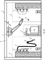
- Fig. 5A shows a side view of the system 1 as a whole.
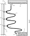
- the first magazine 5 and the second magazine 7 comprise, respectively, a first cable drag chain 51 and a second cable drag chain 71.
- the first cable drag chain 51 and the second cable drag chain 71 comprise coupling means 52,72 adapted to connect the fluid transportation means 25, in particular a tube 25, to a tank located in the first magazine 5 or in the second magazine 7.
- said coupling means 52,72 are arranged vertically with respect to the support plane of the first magazine 5 and of the second magazine 7, and one above the other.
- a tube 25 carrying a specific coloured fluid is connected to each coupling means 52,72.
- a delivery valve V m is connected to one end of the tube 25.
- the tube 25 is flexible, and is therefore advantageously laid on a support line 29 that extends throughout the length of the dosage line 3.
- the support line 29 avoids any interference between the tubes 25 when they are arranged over the delivery actuators E i .
- each valve 27 may be provided with a fluid recirculation tube.
- the robot 9 can move in two directions, i.e. longitudinally (arrow designated RO) and transversally (arrow designated RV) relative to the dosage line 3. More in detail, the robot 9 is an electromechanical arm equipped with a clamp 91 at one end, possibly an extensible one, which can work in the area comprised between the first magazine 5 and the second magazine 7, and at least throughout the length of the dosage line 3. Preferably, the robot 9 is anchored to a portal 8 provided with guiding means adapted to allow the same robot 9 to move in the two longitudinal and transversal directions.
- RO longitudinally
- RV transversally
- the robot 9 can also be used for moving the containers B n along the dosage line 3 during the dosage process.
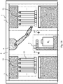
- the first magazine 5 and the second magazine 7 comprise a first monorail assembly 53 and a second monorail assembly 73, to which the fluid transportation means 25 can be connected.
- the first magazine 5 is identical to the second magazine 7, and therefore only the first magazine 5 will be described in detail.
- the first monorail assembly 53 comprises at least one monorail 31 where carriages 33 are arranged, which can translate in the direction of the monorail 31, said carriages 33 being each equipped with a support 34 for bearing the tube 25 that transports the coloured fluid from a drum 35 to the delivery valve V m , designated by reference numeral 27, by means of a delivery pump 36.
- the at least one monorail 31 is arranged parallel to the dosage line 3; the robot 9 can thus operate along all monorails 31, so as to be able to pick up the delivery valves V m from their storage points D m .
- the delivery valves V m are positioned at the corresponding storage points D m on a rack 37 which is also useful as a support for the tube 25.
- said second configuration of the fluid magazine 5,7 allows the tube 25 to be easily extended because, when the robot 9 picks up and moves the delivery valve V m on the delivery actuator E i , the tube 25 will extend due to the carriages 33 running along the monorail 31.
- the method further envisages to:
- the dosage process may also end on the basis of the number of containers B n to be filled up with the composition of a formula, i.e. when the preset number of containers B n to be filled up is reached.
- a user may store said preset number of containers B n to be filled up into the memory means of the control unit 11, which will then verify, by means of a count sensor positioned along the dosage line 3, the number of containers B n containing the finished product.
- the preset number of containers B n is reached, the dosage process will end.
- the method optionally envisages to:
- washing and drying operations may alternatively be carried out when the fluid for the current formula no longer needs to be used during the dosage process, in particular when the dosage line 3 is executing the step of removing the containers B (final step of the dosage process).
- the robot 9 will bring the delivery valves V m back to their respective storage points D m .
- the method according to the invention envisages to bring the delivery valves V m back to their respective storage points D m in reverse order compared to the order in which the same delivery valves V m were picked up from their storage point D m .
- the method envisages to bring the delivery valves V m back to their respective storage points D m in an arbitrary order.
- the present invention also relates to a computer program product which can be loaded into memory means of said control unit 11 and which is adapted to implement the method according to the invention.
- a first advantage of the system and method for delivery of fluids according to the present invention is that they ensure better system automation and shorter production times.
- a second advantage of the invention is that it ensures higher production volumes of finished product.
- a further advantage of the invention is that the working environment will be cleaner and safer for the operators.
- the system for delivery of fluids may comprise a plurality of dosage lines, in particular arranged side by side, so that production can be maximized.
- the robot may pick up the delivery valves V m in a different order than that in which the fluids are loaded for the composition of the final formula.
Landscapes
- Chemical & Material Sciences (AREA)
- Chemical Kinetics & Catalysis (AREA)
- Medical Preparation Storing Or Oral Administration Devices (AREA)
Claims (21)
- System (1) zur Abgabe von Fluiden, insbesondere farbigen Fluiden, das angepasst ist, einen Dosierprozess durchzuführen, wobei Behälter (Bn) gefüllt werden, um ein Endprodukt gemäß einer gegebenen Formel zu erhalten, wobei die Formel für die Dosierung und/oder Zusammensetzung eines oder mehrerer Fluide repräsentativ ist, wobei das System (1) umfasst:- mindestens eine Dosierlinie (3) mit mindestens einer Station (Sp);- mindestens ein Magazin (5,7) mit Abgabeventilen (Vm), wobei ein Speicherpunkt (Dm) jedem von ihnen zugeordnet ist, und wobei sie mit einem Tank, der ein Fluid enthält, mittels Fluidtransportmitteln (25,26) verbunden sind;- einen Roboter (9), der angepasst ist, mindestens eines der Abgabeventile (Vm) vom Speicherpunkt (Dm) aufzunehmen und es an einem Dosierpunkt der mindestens einen Station (Sp) zu platzieren;- einer Steuereinheit (11), die angepasst ist, die mindestens eine Dosierlinie(3), das mindestens eine Magazin (5,7) und den Roboter (9) zu steuern und zu überwachen,wobei das System (1) dadurch gekennzeichnet ist, dass
das mindestens eine Magazin (5,7) eine Kabelschleppkette (51,71) umfasst, die Kupplungsmittel (52,72) umfasst, die angepasst sind, die Fluidtransportmittel (25) mit dem Tank des mindestens einen Magazins (5,7) zu verbinden. - System (1) nach Anspruch 1, wobei die mindestens eine Dosierlinie (3) mehrere Stationen (Sp) umfasst und eingerichtet ist, die Container (Bn) von einer ersten Station zu einer zweiten Station der mehreren Stationen (Sp) zu bewegen und die Steuereinheit (11) eingerichtet ist, das Fluid mit einer Station der mehreren Stationen (Sp) während der Dauer des Dosierprozesses zu assoziieren.
- System (1) nach Anspruch 2, wobei die mindestens eine Station (Sp) eine Waage aufweist, die angepasst ist, das Gewicht eines Containers (Bn) während der Abgabe des Fluids zu bestimmen, und wobei die Steuereinheit (11) die Bewegung der Container (Bn) von der ersten Station zu der zweiten Station steuert, wenn das Fluid einen Grenzwert erreicht, der durch die Formel vorgegeben ist.
- System (1) nach einem oder mehreren der vorhergehenden Ansprüche, wobei die Steuereinheit (11) die Abgabeventile (Vm) steuert, sobald sie an dem Dosierpunkt platziert worden sind, um während der Dauer des Dosierprozesses stationär zu bleiben.
- System (1) nach einem oder mehreren der vorhergehenden Ansprüche, wobei die mindestens eine Station (Sp) ein Waschmodul (Lj) umfasst, das in Nähe zum Dosierpunkt angeordnet und angepasst ist, die Abgabeventile (Vm) am Ende des Dosierprozesses zu waschen.
- System (1) nach dem vorhergehenden Anspruch, wobei das Waschmodul (Lj) angepasst ist, die Abgabeventile (Vm) am Ende des Dosierprozesses zu trocknen.
- System (1) nach einem oder mehreren der vorhergehenden Ansprüche, wobei der Roboter (9) die Abgabeventile (Vm) zurück zu ihren entsprechenden Speicherpunkten (Dm) nach dem Ende des Dosierprozesses bewegt.
- System (1) nach einem oder mehreren der vorhergehenden Ansprüche, wobei das mindestens eine Magazin (5,7) auf mindestens einer Seite der mindestens einen Dosierlinie (3) angeordnet ist.
- System (1) nach einem oder mehreren der vorhergehenden Ansprüche, wobei der Roboter (9) frei ist, sich vorwärts und rückwärts in einer Längsrichtung und in einer Querrichtung der mindestens einen Dosierlinie (3) zu bewegen.
- System (1) nach einem oder mehreren der vorhergehenden Ansprüche, wobei die mindestens eine Dosierlinie (3) Bewegungsmittel (31), insbesondere ein automatisches Förderband, umfasst, das angepasst ist, die Container (Bn) auf Haltemitteln der mindestens einen Dosierlinie (3) zu bewegen.
- System (1) nach einem oder mehreren der Ansprüche 1 bis 9, wobei der Roboter (9) angepasst ist, die Container (Bn) auf Haltemitteln der mindestens einen Dosierlinie (3) zu bewegen.
- System (1) nach Anspruch 1, wobei die Kupplungsmittel (52,72) vertikal bezogen auf eine Halteplatte des mindestens einen Magazins (5,7) und eines über dem anderen angeordnet sind.
- System (1) nach einem oder mehreren der Ansprüche 1 bis 11, wobei das mindestens eine Magazin (5,7) eine Einschienenbahnanordnung (53,73) aufweist, mit der die Fluidtransportmittel (25) verbunden werden können.
- Verfahren zum Abgeben eines Fluids unter Verwendung eines Systems nach Anspruch 1, insbesondere farbiger Fluide, das angepasst ist, einen Dosierprozess durchzuführen, wobei Container (Bn) gefüllt werden, um ein Endprodukt gemäß einer gegebenen Formel zu erhalten, wobei die Formel für die Dosierung und/oder Zusammensetzung eines oder mehrerer Fluide repräsentativ ist, wobei das Verfahren die Schritte umfasst:- Aufnehmen eines Abgabeventils (Vm) von einem Speicherpunkt (Dm) mindestens eines Magazins (5,7), das eine Kabelschleppkette (51,71) umfasst, die Kupplungsmittel (52,72) umfasst, die angepasst sind, die Fluidtransportmittel (25) mit dem Tank des mindestens einen Magazins (5,7) zu verbinden und sie an einem Dosierpunkt (Ei) mindestens einer Dosierlinie (3) zu platzieren, durch einen Roboter (9);- Steuern der Abgabe des Fluids durch einen Abgabeaktuator (Ei) in einen ersten Container (Bn), der an einer Station (Sp) der mindestens einen Dosierlinie (3) angeordnet ist.
- Verfahren nach Anspruch 14, wobei es vorgesehen ist zum:- Bewegen des ersten Containers (Bn) von einer ersten Station zu einer zweiten Station;- Platzieren des zweiten Containers (Bn) am Eingang (13) der mindestens einen Dosierlinie (3);- Wiederholen der vorherigen Schritte bis die Formel vollständig ist, zum Beispiel bis jemand ein Ende des Dosierprozesses wünscht;- Assoziieren eines Fluids mit wenigstens einer Station (Sp), wobei die Assoziierung während der Dauer des Dosierprozesses gültig bleibt.
- Verfahren nach Anspruch 15, wobei der Dosierprozess endet, wenn eine voreingestellte Anzahl von Containern (Bn), die in Übereinstimmung mit der Formel aufgefüllt wurden, erreicht worden ist.
- Verfahren nach einem oder mehreren der Ansprüche 14 bis 16, wobei es vorgesehen ist, mindestens eines der Abgabeventile (Vm) am Ende des Dosierprozesses auszuwaschen.
- Verfahren nach einem oder mehreren der Ansprüche 14 bis 17, wobei es vorgesehen ist, die Abgabeventile (Vm) zu deren entsprechenden Speicherpunkten (Dm) mittels des Roboters (9) nach dem Ende des Dosierprozesses zurückzubringen.
- Verfahren nach Anspruch 18, wobei der Schritt des Zurückbringens der Abgabeventile (Vm) zu ihren entsprechenden Speicherpunkten (Dm) in umgekehrter Reihenfolge verglichen zu der Reihenfolge ausgeführt wird, in der die Abgabeventile (Vm) von ihrem Speicherpunkt (Dm) aufgenommen wurden.
- Verfahren nach einem oder mehreren der Ansprüche 15 bis 19, wobei der Schritt des Bewegens des ersten Containers (Bn) von einer ersten Station zu einer zweiten Station durch den Roboter (9) während des Dosierprozesses ausgeführt wird.
- Computerprogrammprodukt, das in einen Speicher der Steuereinheit (11) geladen werden kann und das angepasst ist, das Verfahren nach einem der Ansprüche 14 bis 20 auszuführen.
Applications Claiming Priority (1)
| Application Number | Priority Date | Filing Date | Title |
|---|---|---|---|
| ITUB2015A000282A ITUB20150282A1 (it) | 2015-04-20 | 2015-04-20 | Sistema e metodo per l’erogazione di fluidi, in particolare fluidi colorati |
Publications (2)
| Publication Number | Publication Date |
|---|---|
| EP3085437A1 EP3085437A1 (de) | 2016-10-26 |
| EP3085437B1 true EP3085437B1 (de) | 2018-09-19 |
Family
ID=53385820
Family Applications (1)
| Application Number | Title | Priority Date | Filing Date |
|---|---|---|---|
| EP16166016.2A Not-in-force EP3085437B1 (de) | 2015-04-20 | 2016-04-19 | System und verfahren zur abgabe von fluiden, insbesondere farbigen fluiden |
Country Status (2)
| Country | Link |
|---|---|
| EP (1) | EP3085437B1 (de) |
| IT (1) | ITUB20150282A1 (de) |
Families Citing this family (4)
| Publication number | Priority date | Publication date | Assignee | Title |
|---|---|---|---|---|
| CA3061671A1 (en) * | 2017-05-19 | 2018-11-22 | Basf Coatings Gmbh | Modular production system for formulations |
| DE102017130737A1 (de) * | 2017-12-20 | 2019-06-27 | Delphi Salesconsulting Ag | Verfahren zur automatisierten Herstellung von Cremes |
| IT201900014622A1 (it) * | 2019-08-12 | 2021-02-12 | Corob Spa | Assieme di magazzino e metodo per la gestione integrata di un ordine di acquisto di prodotti coloranti fluidi |
| CN115253867B (zh) * | 2022-06-23 | 2024-04-30 | 四川三联新材料有限公司 | 一种流水式香精香料生产工艺 |
Family Cites Families (5)
| Publication number | Priority date | Publication date | Assignee | Title |
|---|---|---|---|---|
| JPS63109333A (ja) * | 1986-10-28 | 1988-05-14 | Nippon Paint Co Ltd | 液体容器の自動搬送計量装置 |
| US5215131A (en) * | 1991-11-14 | 1993-06-01 | Poy George L | Automatic liquid delivery system |
| KR101107851B1 (ko) * | 2010-11-12 | 2012-02-07 | 삼성엘이디 주식회사 | 형광체 자동 배합기 및 형광체 자동 배합 방법 |
| ITTO20110232A1 (it) * | 2011-03-14 | 2011-06-13 | Hero Europ S R L | Tintometro automatico. |
| US9849431B2 (en) * | 2012-07-13 | 2017-12-26 | Ppg Industries Ohio, Inc. | System and method for automated production, application and evaluation of coating compositions |
-
2015
- 2015-04-20 IT ITUB2015A000282A patent/ITUB20150282A1/it unknown
-
2016
- 2016-04-19 EP EP16166016.2A patent/EP3085437B1/de not_active Not-in-force
Non-Patent Citations (1)
| Title |
|---|
| None * |
Also Published As
| Publication number | Publication date |
|---|---|
| EP3085437A1 (de) | 2016-10-26 |
| ITUB20150282A1 (it) | 2016-10-20 |
Similar Documents
| Publication | Publication Date | Title |
|---|---|---|
| EP3085437B1 (de) | System und verfahren zur abgabe von fluiden, insbesondere farbigen fluiden | |
| CN110267749B (zh) | 弯曲工具存储装置以及用于供给压弯机的方法 | |
| US9958851B2 (en) | Apparatus for the automated removal of workpieces arranged in a container | |
| EP2437984B1 (de) | Vorrichtung und verfahren zur behandlung von behältnisse für flüssigkeiten und ladevorrichtung für solche behältnisse | |
| CN207810399U (zh) | 缓存库、缓存装置、拣选线及立体仓库 | |
| EP2682197B1 (de) | Maschine und Verfahren zur Behandlung von Behältern für Flüssigkeiten | |
| US9828194B2 (en) | Station for loading and unloading piece-carrying containers | |
| CN203903241U (zh) | 一种自动上下料系统 | |
| CN102083719A (zh) | 悬挂轨道系统和带有这种系统的浸渍处理设备 | |
| DE102013100048A1 (de) | Kommissioniereinrichtung | |
| CN207243009U (zh) | 一种包装箱自动装车机器人 | |
| CN104511673B (zh) | 一种核燃料元件包壳管点钎焊一体化装置 | |
| IT201800004759A1 (it) | Linea di assemblaggio di sottoinsiemi di carrozzeria di autoveicoli | |
| US12110180B2 (en) | Movement device | |
| EP3696119A1 (de) | Vorrichtung zum umstülpen von kastenförmigen behältern und entsprechendes verfahren | |
| CN107380869A (zh) | 一种适用于货运集装箱的物流取码系统的使用方法 | |
| WO2010140042A2 (en) | Machine and method for treating containers of liquids, and manipulator device for said containers | |
| EP2345605B1 (de) | Vorrichtung zum automatischen Übertragen verpackter pharmazeutischer Produkte | |
| ITMO20080268A1 (it) | Impianto per la fornitura di prodotti da pallettizzare e procedimento per la composizione di pallet misti. | |
| US20150225096A1 (en) | System for packaging products | |
| CN210557755U (zh) | 一种双层s型运输的缓存线 | |
| JP7524311B2 (ja) | 棒材を保管する機器および方法 | |
| CN103407748B (zh) | 物料涂装自动输送线吊具空工位返回的工艺方法 | |
| CN116639413A (zh) | 一种可自动识别上仓的换仓机器人 | |
| JP2022546426A (ja) | 棒材を送給する機器および方法 |
Legal Events
| Date | Code | Title | Description |
|---|---|---|---|
| PUAI | Public reference made under article 153(3) epc to a published international application that has entered the european phase |
Free format text: ORIGINAL CODE: 0009012 |
|
| AK | Designated contracting states |
Kind code of ref document: A1 Designated state(s): AL AT BE BG CH CY CZ DE DK EE ES FI FR GB GR HR HU IE IS IT LI LT LU LV MC MK MT NL NO PL PT RO RS SE SI SK SM TR |
|
| AX | Request for extension of the european patent |
Extension state: BA ME |
|
| STAA | Information on the status of an ep patent application or granted ep patent |
Free format text: STATUS: REQUEST FOR EXAMINATION WAS MADE |
|
| 17P | Request for examination filed |
Effective date: 20170421 |
|
| RBV | Designated contracting states (corrected) |
Designated state(s): AL AT BE BG CH CY CZ DE DK EE ES FI FR GB GR HR HU IE IS IT LI LT LU LV MC MK MT NL NO PL PT RO RS SE SI SK SM TR |
|
| GRAP | Despatch of communication of intention to grant a patent |
Free format text: ORIGINAL CODE: EPIDOSNIGR1 |
|
| STAA | Information on the status of an ep patent application or granted ep patent |
Free format text: STATUS: GRANT OF PATENT IS INTENDED |
|
| INTG | Intention to grant announced |
Effective date: 20180411 |
|
| GRAS | Grant fee paid |
Free format text: ORIGINAL CODE: EPIDOSNIGR3 |
|
| GRAA | (expected) grant |
Free format text: ORIGINAL CODE: 0009210 |
|
| STAA | Information on the status of an ep patent application or granted ep patent |
Free format text: STATUS: THE PATENT HAS BEEN GRANTED |
|
| AK | Designated contracting states |
Kind code of ref document: B1 Designated state(s): AL AT BE BG CH CY CZ DE DK EE ES FI FR GB GR HR HU IE IS IT LI LT LU LV MC MK MT NL NO PL PT RO RS SE SI SK SM TR |
|
| REG | Reference to a national code |
Ref country code: GB Ref legal event code: FG4D |
|
| REG | Reference to a national code |
Ref country code: CH Ref legal event code: EP |
|
| REG | Reference to a national code |
Ref country code: AT Ref legal event code: REF Ref document number: 1042595 Country of ref document: AT Kind code of ref document: T Effective date: 20181015 |
|
| REG | Reference to a national code |
Ref country code: IE Ref legal event code: FG4D |
|
| REG | Reference to a national code |
Ref country code: DE Ref legal event code: R096 Ref document number: 602016005644 Country of ref document: DE |
|
| REG | Reference to a national code |
Ref country code: NL Ref legal event code: MP Effective date: 20180919 |
|
| PG25 | Lapsed in a contracting state [announced via postgrant information from national office to epo] |
Ref country code: FI Free format text: LAPSE BECAUSE OF FAILURE TO SUBMIT A TRANSLATION OF THE DESCRIPTION OR TO PAY THE FEE WITHIN THE PRESCRIBED TIME-LIMIT Effective date: 20180919 Ref country code: NO Free format text: LAPSE BECAUSE OF FAILURE TO SUBMIT A TRANSLATION OF THE DESCRIPTION OR TO PAY THE FEE WITHIN THE PRESCRIBED TIME-LIMIT Effective date: 20181219 Ref country code: RS Free format text: LAPSE BECAUSE OF FAILURE TO SUBMIT A TRANSLATION OF THE DESCRIPTION OR TO PAY THE FEE WITHIN THE PRESCRIBED TIME-LIMIT Effective date: 20180919 Ref country code: SE Free format text: LAPSE BECAUSE OF FAILURE TO SUBMIT A TRANSLATION OF THE DESCRIPTION OR TO PAY THE FEE WITHIN THE PRESCRIBED TIME-LIMIT Effective date: 20180919 Ref country code: BG Free format text: LAPSE BECAUSE OF FAILURE TO SUBMIT A TRANSLATION OF THE DESCRIPTION OR TO PAY THE FEE WITHIN THE PRESCRIBED TIME-LIMIT Effective date: 20181219 Ref country code: LT Free format text: LAPSE BECAUSE OF FAILURE TO SUBMIT A TRANSLATION OF THE DESCRIPTION OR TO PAY THE FEE WITHIN THE PRESCRIBED TIME-LIMIT Effective date: 20180919 Ref country code: GR Free format text: LAPSE BECAUSE OF FAILURE TO SUBMIT A TRANSLATION OF THE DESCRIPTION OR TO PAY THE FEE WITHIN THE PRESCRIBED TIME-LIMIT Effective date: 20181220 |
|
| REG | Reference to a national code |
Ref country code: LT Ref legal event code: MG4D |
|
| PG25 | Lapsed in a contracting state [announced via postgrant information from national office to epo] |
Ref country code: AL Free format text: LAPSE BECAUSE OF FAILURE TO SUBMIT A TRANSLATION OF THE DESCRIPTION OR TO PAY THE FEE WITHIN THE PRESCRIBED TIME-LIMIT Effective date: 20180919 Ref country code: HR Free format text: LAPSE BECAUSE OF FAILURE TO SUBMIT A TRANSLATION OF THE DESCRIPTION OR TO PAY THE FEE WITHIN THE PRESCRIBED TIME-LIMIT Effective date: 20180919 Ref country code: LV Free format text: LAPSE BECAUSE OF FAILURE TO SUBMIT A TRANSLATION OF THE DESCRIPTION OR TO PAY THE FEE WITHIN THE PRESCRIBED TIME-LIMIT Effective date: 20180919 |
|
| REG | Reference to a national code |
Ref country code: AT Ref legal event code: MK05 Ref document number: 1042595 Country of ref document: AT Kind code of ref document: T Effective date: 20180919 |
|
| PG25 | Lapsed in a contracting state [announced via postgrant information from national office to epo] |
Ref country code: IS Free format text: LAPSE BECAUSE OF FAILURE TO SUBMIT A TRANSLATION OF THE DESCRIPTION OR TO PAY THE FEE WITHIN THE PRESCRIBED TIME-LIMIT Effective date: 20190119 Ref country code: AT Free format text: LAPSE BECAUSE OF FAILURE TO SUBMIT A TRANSLATION OF THE DESCRIPTION OR TO PAY THE FEE WITHIN THE PRESCRIBED TIME-LIMIT Effective date: 20180919 Ref country code: NL Free format text: LAPSE BECAUSE OF FAILURE TO SUBMIT A TRANSLATION OF THE DESCRIPTION OR TO PAY THE FEE WITHIN THE PRESCRIBED TIME-LIMIT Effective date: 20180919 Ref country code: ES Free format text: LAPSE BECAUSE OF FAILURE TO SUBMIT A TRANSLATION OF THE DESCRIPTION OR TO PAY THE FEE WITHIN THE PRESCRIBED TIME-LIMIT Effective date: 20180919 Ref country code: PL Free format text: LAPSE BECAUSE OF FAILURE TO SUBMIT A TRANSLATION OF THE DESCRIPTION OR TO PAY THE FEE WITHIN THE PRESCRIBED TIME-LIMIT Effective date: 20180919 Ref country code: RO Free format text: LAPSE BECAUSE OF FAILURE TO SUBMIT A TRANSLATION OF THE DESCRIPTION OR TO PAY THE FEE WITHIN THE PRESCRIBED TIME-LIMIT Effective date: 20180919 Ref country code: CZ Free format text: LAPSE BECAUSE OF FAILURE TO SUBMIT A TRANSLATION OF THE DESCRIPTION OR TO PAY THE FEE WITHIN THE PRESCRIBED TIME-LIMIT Effective date: 20180919 Ref country code: EE Free format text: LAPSE BECAUSE OF FAILURE TO SUBMIT A TRANSLATION OF THE DESCRIPTION OR TO PAY THE FEE WITHIN THE PRESCRIBED TIME-LIMIT Effective date: 20180919 |
|
| PG25 | Lapsed in a contracting state [announced via postgrant information from national office to epo] |
Ref country code: PT Free format text: LAPSE BECAUSE OF FAILURE TO SUBMIT A TRANSLATION OF THE DESCRIPTION OR TO PAY THE FEE WITHIN THE PRESCRIBED TIME-LIMIT Effective date: 20190119 Ref country code: SM Free format text: LAPSE BECAUSE OF FAILURE TO SUBMIT A TRANSLATION OF THE DESCRIPTION OR TO PAY THE FEE WITHIN THE PRESCRIBED TIME-LIMIT Effective date: 20180919 Ref country code: SK Free format text: LAPSE BECAUSE OF FAILURE TO SUBMIT A TRANSLATION OF THE DESCRIPTION OR TO PAY THE FEE WITHIN THE PRESCRIBED TIME-LIMIT Effective date: 20180919 |
|
| REG | Reference to a national code |
Ref country code: DE Ref legal event code: R097 Ref document number: 602016005644 Country of ref document: DE |
|
| PLBE | No opposition filed within time limit |
Free format text: ORIGINAL CODE: 0009261 |
|
| STAA | Information on the status of an ep patent application or granted ep patent |
Free format text: STATUS: NO OPPOSITION FILED WITHIN TIME LIMIT |
|
| PG25 | Lapsed in a contracting state [announced via postgrant information from national office to epo] |
Ref country code: DK Free format text: LAPSE BECAUSE OF FAILURE TO SUBMIT A TRANSLATION OF THE DESCRIPTION OR TO PAY THE FEE WITHIN THE PRESCRIBED TIME-LIMIT Effective date: 20180919 |
|
| 26N | No opposition filed |
Effective date: 20190620 |
|
| PG25 | Lapsed in a contracting state [announced via postgrant information from national office to epo] |
Ref country code: SI Free format text: LAPSE BECAUSE OF FAILURE TO SUBMIT A TRANSLATION OF THE DESCRIPTION OR TO PAY THE FEE WITHIN THE PRESCRIBED TIME-LIMIT Effective date: 20180919 |
|
| REG | Reference to a national code |
Ref country code: CH Ref legal event code: PL |
|
| REG | Reference to a national code |
Ref country code: BE Ref legal event code: MM Effective date: 20190430 |
|
| PG25 | Lapsed in a contracting state [announced via postgrant information from national office to epo] |
Ref country code: LU Free format text: LAPSE BECAUSE OF NON-PAYMENT OF DUE FEES Effective date: 20190419 Ref country code: MC Free format text: LAPSE BECAUSE OF FAILURE TO SUBMIT A TRANSLATION OF THE DESCRIPTION OR TO PAY THE FEE WITHIN THE PRESCRIBED TIME-LIMIT Effective date: 20180919 |
|
| PG25 | Lapsed in a contracting state [announced via postgrant information from national office to epo] |
Ref country code: CH Free format text: LAPSE BECAUSE OF NON-PAYMENT OF DUE FEES Effective date: 20190430 Ref country code: LI Free format text: LAPSE BECAUSE OF NON-PAYMENT OF DUE FEES Effective date: 20190430 |
|
| PG25 | Lapsed in a contracting state [announced via postgrant information from national office to epo] |
Ref country code: BE Free format text: LAPSE BECAUSE OF NON-PAYMENT OF DUE FEES Effective date: 20190430 |
|
| PG25 | Lapsed in a contracting state [announced via postgrant information from national office to epo] |
Ref country code: TR Free format text: LAPSE BECAUSE OF FAILURE TO SUBMIT A TRANSLATION OF THE DESCRIPTION OR TO PAY THE FEE WITHIN THE PRESCRIBED TIME-LIMIT Effective date: 20180919 |
|
| PG25 | Lapsed in a contracting state [announced via postgrant information from national office to epo] |
Ref country code: IE Free format text: LAPSE BECAUSE OF NON-PAYMENT OF DUE FEES Effective date: 20190419 |
|
| PG25 | Lapsed in a contracting state [announced via postgrant information from national office to epo] |
Ref country code: CY Free format text: LAPSE BECAUSE OF FAILURE TO SUBMIT A TRANSLATION OF THE DESCRIPTION OR TO PAY THE FEE WITHIN THE PRESCRIBED TIME-LIMIT Effective date: 20180919 |
|
| PG25 | Lapsed in a contracting state [announced via postgrant information from national office to epo] |
Ref country code: HU Free format text: LAPSE BECAUSE OF FAILURE TO SUBMIT A TRANSLATION OF THE DESCRIPTION OR TO PAY THE FEE WITHIN THE PRESCRIBED TIME-LIMIT; INVALID AB INITIO Effective date: 20160419 Ref country code: MT Free format text: LAPSE BECAUSE OF FAILURE TO SUBMIT A TRANSLATION OF THE DESCRIPTION OR TO PAY THE FEE WITHIN THE PRESCRIBED TIME-LIMIT Effective date: 20180919 |
|
| PGFP | Annual fee paid to national office [announced via postgrant information from national office to epo] |
Ref country code: IT Payment date: 20210430 Year of fee payment: 6 Ref country code: DE Payment date: 20210427 Year of fee payment: 6 Ref country code: FR Payment date: 20210424 Year of fee payment: 6 |
|
| PGFP | Annual fee paid to national office [announced via postgrant information from national office to epo] |
Ref country code: GB Payment date: 20210422 Year of fee payment: 6 |
|
| REG | Reference to a national code |
Ref country code: DE Ref legal event code: R079 Ref document number: 602016005644 Country of ref document: DE Free format text: PREVIOUS MAIN CLASS: B01F0013100000 Ipc: B01F0033800000 |
|
| PG25 | Lapsed in a contracting state [announced via postgrant information from national office to epo] |
Ref country code: MK Free format text: LAPSE BECAUSE OF FAILURE TO SUBMIT A TRANSLATION OF THE DESCRIPTION OR TO PAY THE FEE WITHIN THE PRESCRIBED TIME-LIMIT Effective date: 20180919 |
|
| REG | Reference to a national code |
Ref country code: DE Ref legal event code: R119 Ref document number: 602016005644 Country of ref document: DE |
|
| GBPC | Gb: european patent ceased through non-payment of renewal fee |
Effective date: 20220419 |
|
| PG25 | Lapsed in a contracting state [announced via postgrant information from national office to epo] |
Ref country code: GB Free format text: LAPSE BECAUSE OF NON-PAYMENT OF DUE FEES Effective date: 20220419 Ref country code: FR Free format text: LAPSE BECAUSE OF NON-PAYMENT OF DUE FEES Effective date: 20220430 Ref country code: DE Free format text: LAPSE BECAUSE OF NON-PAYMENT OF DUE FEES Effective date: 20221103 |
|
| PG25 | Lapsed in a contracting state [announced via postgrant information from national office to epo] |
Ref country code: IT Free format text: LAPSE BECAUSE OF NON-PAYMENT OF DUE FEES Effective date: 20220419 |