EP3085343A1 - Orthese zur beübung eines sprunggelenks - Google Patents
Orthese zur beübung eines sprunggelenks Download PDFInfo
- Publication number
- EP3085343A1 EP3085343A1 EP16166186.3A EP16166186A EP3085343A1 EP 3085343 A1 EP3085343 A1 EP 3085343A1 EP 16166186 A EP16166186 A EP 16166186A EP 3085343 A1 EP3085343 A1 EP 3085343A1
- Authority
- EP
- European Patent Office
- Prior art keywords
- ankle
- axis
- rotation
- lower leg
- joint
- Prior art date
- Legal status (The legal status is an assumption and is not a legal conclusion. Google has not performed a legal analysis and makes no representation as to the accuracy of the status listed.)
- Granted
Links
Images


Classifications
-
- A—HUMAN NECESSITIES
- A61—MEDICAL OR VETERINARY SCIENCE; HYGIENE
- A61F—FILTERS IMPLANTABLE INTO BLOOD VESSELS; PROSTHESES; DEVICES PROVIDING PATENCY TO, OR PREVENTING COLLAPSING OF, TUBULAR STRUCTURES OF THE BODY, e.g. STENTS; ORTHOPAEDIC, NURSING OR CONTRACEPTIVE DEVICES; FOMENTATION; TREATMENT OR PROTECTION OF EYES OR EARS; BANDAGES, DRESSINGS OR ABSORBENT PADS; FIRST-AID KITS
- A61F5/00—Orthopaedic methods or devices for non-surgical treatment of bones or joints; Nursing devices; Anti-rape devices
- A61F5/01—Orthopaedic devices, e.g. splints, casts or braces
- A61F5/0102—Orthopaedic devices, e.g. splints, casts or braces specially adapted for correcting deformities of the limbs or for supporting them; Ortheses, e.g. with articulations
- A61F5/0127—Orthopaedic devices, e.g. splints, casts or braces specially adapted for correcting deformities of the limbs or for supporting them; Ortheses, e.g. with articulations for the feet
Definitions
- the present invention relates to an orthosis for exercising an ankle during, during, or after correction of a malposition of the ankle, for example, a dynamic clubfoot or cusp foot malalignment.
- orthoses are known with which a malposition of the ankle can be treated specifically and easily. These usually have an upper shell part for receiving a lower leg and a lower shell part for receiving a foot. The two shell parts are mutually rotatable and slidably connected via an orthotic joint in order to set a correction position for the ankle exactly. The orthotic joint is further equipped with a locking device to maintain the adjusted correction position of the ankle.
- the problem here is that the ankle is immobilized for a long time to get used to the ankle ligaments and muscles to the corrected joint position. Prolonged immobilization can stiffen the treated joint. This stiffening can then be reversed, if necessary, by a physiotherapeutic treatment after the correction of the joint deformity, which however means an extension of the duration of therapy. Furthermore, the stiffening may also be associated with joint pain.
- orthoses are already known which allow a training of the upper part of the ankle (also called upper ankle joint) during or after the correction of a malposition of the ankle.
- the orthoses are equipped with orthotic joints, which allow a movement of the upper ankle along predetermined degrees of freedom and in a certain range of motion.
- the upper ankle is formed by the distal (lower) ends of the fibula and tibia and the talus.
- the lower ankle is u.a. formed by the ankle bone and the heel bone located below (distal) the ankle bone.
- orthotic devices for the upper ankle joint can not be used to exercise the lower ankle, since the upper and lower ankle joints have different axes of rotation.
- the axis of rotation of the upper ankle usually extends at an angle of 68 ° to 88 ° to the longitudinal axis of the lower leg bone through the ankle.
- the axis of rotation of the lower ankle runs obliquely in an open angle to the front and upwards of about 42 ° and in an also open to the front and the great toe angle of about 16 ° to the longitudinal axis of the foot. Therefore, a completely differently constructed orthosis for practicing the lower ankle as for the exercise of the upper ankle is necessary.
- the object of the present invention to provide an orthosis, the exercise or the leadership of the lower ankle allows for, during or after a correction of a malposition of the ankle and thus prevents stiffening of the lower ankle.
- the orthosis for exercising a human ankle having an upper and a lower ankle in a corrected position, a foot part for receiving a foot and a lower leg part for receiving a lower leg.
- the foot part and the lower leg part are aligned with each other such that the ankle joint can be brought into a corrected position.
- both the upper and lower ankle can be brought into a corrected position.
- the orthosis according to the invention furthermore has at least one first orthotic joint and is characterized in that the first orthotic joint permits rotation of the foot part relative to the lower leg part about a first axis of rotation, wherein the first axis of rotation corresponds to a rotational axis of the lower ankle in the corrected position of the ankle.
- the orthosis according to the invention to correct a malposition of the ankle, in particular of the upper and / or lower ankle, and at the same time to ensure a mobility of the lower ankle about the first axis of rotation.
- the lower ankle can be exercised in the corrected position and stiffening of the ankle can be prevented. This shortens the treatment time and improves the well-being of the patient.
- the first axis of rotation at an angle between 30 ° and 50 °, preferably between 39 ° and 42 °, in the direction ofreciteiloberseite to a horizontal plane through the foot and at an angle between 10 ° and 20 °, preferably between 12 ° and 16 °, in the direction of a predominantlyteilinnenseite to a sagittal plane pass through the foot part through a heel area of the foot part, in which the lower ankle can be positioned.
- the sagittal plane through the foot part denotes a plane which contains a longitudinal axis of the foot part and a longitudinal axis of the lower leg part when the foot part is in a position not rotated relative to the lower leg part.
- the sagittal plane thus cuts the foot part and the lower leg part lengthwise into two halves.
- the inside of the foot part corresponds to a side of the foot part which can be aligned to the middle of the body, when the orthosis is applied to a foot to be treated.
- the horizontal plane through the foot part denotes a plane which contains the longitudinal axis of the foot part and runs largely perpendicular to the longitudinal axis of the lower leg part.
- the upper part of the foot corresponds to a side of the foot part which can be aligned with the foot span when the orthosis is applied to a foot to be treated.
- the first axis of rotation therefore extends obliquely from above a big toe area to a lower, outer heel area through the lower ankle joint.
- the first orthotic joint can be designed in such a way that a position of the first axis of rotation can also be subsequently displaced and more precisely adapted to an ankle to be treated.
- the orthosis may have a second orthotic joint, which allows a rotation of the foot relative to the lower leg part about a second axis of rotation, wherein the second axis of rotation corresponds to a rotational axis of the upper ankle in the corrected position of the ankle.
- the second axis of rotation can be largely perpendicular, preferably at an angle between 70 ° and 90 °, in particular at an angle of 80 ° to the longitudinal axis of the lower leg part by an above the heel area of the foot located ankle area of the orthosis, in which the upper ankle is positionable, run.
- the second orthotic joint can in particular be further configured such that a position of the second axis of rotation can also be subsequently displaced and more precisely adapted to an ankle to be treated.
- the first orthotic joint comprises an annular hoop, at whose ends the foot part is rotatably mounted about the first axis of rotation.
- the ends are preferably fixed in holding points of the foot part, in which the first axis of rotation intersects the foot part.
- the ring hoop can then run along the scholarteilinnenseite from the first to the second breakpoint.
- the ring hoop may be rigidly connected to the lower leg part or connected to the lower leg part via the second orthotic joint, depending on whether a second orthotic joint is present or not.
- the lower leg part can be connected via a longitudinal rail with the annular hoop, wherein the second orthotic joint is then arranged in a connection point between the longitudinal rail and the annular hoop.
- the longitudinal rail and the connection point are, like the ring hoop, preferably arranged on an inner side of the orthosis facing the center of the body. This helps to improve the visual appearance of the patient when he wears the orthosis over a longer period of time and thus increases the comfort of the patient.
- connection point and the ring hoop at an outer side facing away from the body center. This would reduce one possible risk of injury to the other leg through contact with the connection point, which due to the construction of the orthosis would protrude slightly to the outside of the foot part.
- the first and / or the second orthotic joint stop elements for limiting a movement of the foot and the lower leg part to each other about the first and / or the second axis of rotation.
- the range of movement of the foot and / or lower leg part can be limited to a certain angular range, on the one hand to achieve an efficient and accurate correction of the malposition of the lower or upper ankle and on the other hand still to ensure a certain mobility.
- the first orthotic joint and / or the second orthotic joint preferably has a ball joint or a hinge joint.
- a ball joint has the advantage that even with small manufacturing tolerances a smooth movement of the foot is made possible with respect to the lower leg part, since a ball joint has a variable in a certain angular range of rotation axis.
- a hinge joint can be set exactly with a hinge joint, the rotation axis and thus a mobility around an exactly set axis of rotation can be ensured.
- first orthotic joint and / or the second orthotic joint with one another to an electronically controlled movement of the foot and lower leg part relative to one another about the first and / or the second axis of rotation.
- the ankle joint can be practiced automatically without the patient or an orthopedist having to manually move the foot part in relation to the lower leg part.
- the first and / or the second orthotic joint may also be designed lockable, if a rest position of the lower and / or the upper ankle over a certain period of time is desired so that, for example, ligaments and muscles can get used to a correction position.
- the present invention also includes a method of exercising a human and ankle ankle joint in a corrected position with an orthosis described above, wherein the foot part is attached to the foot and the lower leg part to the lower leg, thereby the ankle is brought into the corrected position and the foot part relative to the lower leg part about the first and / or second axis of rotation and is turned.
- the present invention also includes a use of an orthosis described above for correcting a misalignment of a human ankle, in particular for correcting a clubfoot and / or a kink foot.
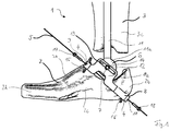
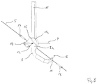
- FIG. 1 shows a first embodiment of an orthosis 1 according to the invention in a side view with a view of a body center facing inside of the orthosis 1.
- the orthosis 1 has a foot part 2 and a movably connected to the foot part 2 lower leg part 3.
- the foot part 2 is designed as a closed ring socket and has an opening in the region of the ankle for applying the foot part 2 to a foot.
- the lower leg part 3 has a substantially cylindrical shape, which has a large opening for applying the lower leg part 3 to a lower leg both on a side facing the foot part 2 and on a side facing away from the foot part 2.
- the foot part 2 has a first orthotic joint 4 in the form of a ring hoop 8 rotatably mounted about a first axis of rotation 5.
- the annular hoop 8 runs on a proximal inner side 2c of the foot part 2 facing the middle of the body.
- the foot part 2 is thus rotatable on the annular hoop 8 about the first axis of rotation 5.
- the first axis of rotation 5 extends obliquely through the foot part 2, from approximately above one of the body center facing, proximal (inner) big toe portion 2d of the foot part 2 to a lower, distal (outer) heel region 2b.
- the first axis of rotation 5 extends at an angle of about 42 ° in the direction of the body center facing proximal alleviatteiloberseite 2a to the MitteIline and at an angle of about 16 ° to the center line in the direction of one of the contemplatteilau callseite 2e facing away foot inside 2c.
- This first axis of rotation 5 corresponds approximately to the axis of rotation of the lower ankle to be positioned in the orthosis 1.
- the ring hoop 8 is rotatably mounted at its upper end to an upper breakpoint 9 by means of a screw 17 and at its lower end to a lower breakpoint 10 by means of a screw 18.
- the upper breakpoint 9 is located at a location of the foot part 2 in which the first axis of rotation 5 intersects the foot part 2 on the foot part upper side 2 a.
- the lower break point 10 is located at a position where the first rotation axis 5 intersects the foot part 2 in the lower heel region 2b.
- the ring hoop 8 thus forms a hinge joint, which is rotatable about the first axis of rotation 5.
- Adjustable stop elements 15, 16 for limiting an angular range of the rotational movement about the first axis 5 are arranged between the ends of the annular hoop 8 and the foot part 2.
- the ring hoop 8 has a bulge 8a located on a foot part inside 2c in the direction of the lower leg part 3 for connecting the ring hoop 8 to the lower leg part 3.
- a longitudinal rail 11 is rigidly attached to the lower leg part 3 parallel to a longitudinal axis of the lower leg part 3 at a proximal inner side of the lower leg part 3 facing the middle of the body. The longitudinal rail 11 overlaps in the region of the bulge 8a with the annular hoop 8.
- the longitudinal rail 11 has a circular disk-shaped end 11a, which with the bulge 8a of the ring hoop 8 in a connection point 12 via a screw 14 to each other about a second axis of rotation. 7 is rotatably connected.
- the bulge 8a and the circular disk-shaped end 11a form a second orthotic joint 6, which is rotatable about the second axis of rotation 7 and is designed as a hinge joint.
- the second axis of rotation 7 extends approximately perpendicular to the longitudinal axes of the foot part 2 and the lower leg part 3 through an area of the orthosis 1, in which the upper ankle joint is positionable.
- connection point 12 which simultaneously represents the position of the axis of the second orthotic joint 6, is located in an elongated groove 13 which is arranged in the bulge 8 a of the ring hoop 8.
- the groove 13 extends approximately parallel to the annular hoop 8 and allows a subsequent adjustment of the position of the second axis of rotation 7 in order to be able to more precisely adapt the orthosis 1 to an ankle to be treated.
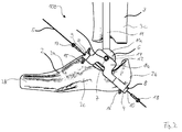
- FIG. 2 shows a second embodiment of an orthosis 100 according to the invention in a side view with a view of the middle of the body facing the inside of the orthosis 100.
- the orthosis 100 has as well as the orthosis 1 in FIG. 1 a foot part 2, a lower leg part 3 movably connected to the foot part 2 and a first orthotic joint 4 and a second orthotic joint 6.
- the orthosis 100 in FIG. 2 only differs from the orthosis 1 of the FIG. 1 in that the bulge 8a of the ring hoop 8 has no groove for adjusting the position of the axis of the second orthotic joint 6 and thus for adapting the second axis of rotation 7. Instead, in the orthosis 100 of the connection point 12 between the ring hoop 8 and the longitudinal rail 11 is fixed.
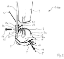
- FIG. 3 shows the braces 1 and 100 FIG. 1 and FIG. 2 in a rear view overlooking the heel area 2b of the foot part 2.
- the second axis of rotation 7 extends approximately perpendicular to the longitudinal axes of the foot part 2 and the lower leg part 3.
- the second axis of rotation thus also extends perpendicular to the sagittal plane through the foot part 2, which divides the foot part 2 longitudinally into two halves.
- the first axis of rotation 5 runs as well as in the FIGS. 1 and 2 recognizable from above a big toe area 2d on the foot part inside 2c to the lower, outer heel area 2b.
- the second orthotic joint 6 is arranged on the bulge 8a of the ring hoop 8 on a side facing the heel region 2b a rear stop element 8c, which limits a rotational movement of the longitudinal rail 11 about the second axis of rotation 7 in the direction of the heel region 2b.
- FIG. 4 shows the braces 1 and 100 FIGS. 1 and 2 As well as an arrangement of the ring hoop 8, the longitudinal rail 11 and the second orthotic joint 6 on one of the body center facing inside of the brace 1 or 100, it would be conceivable, the ring hoop 8, the longitudinal rail 11 and the second orthotic joint 6 to be arranged on a side facing away from the body center outside of the orthosis.
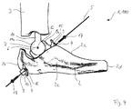
- FIG. 5 shows the braces 1 and 100 FIGS. 1 and 2 in a front view overlooking a toe area of the foot part 2.
- a front stop element 8b of the second orthotic joint 6 is arranged on a side of the bulge 8a of the ring hoop 8 facing the big toe area 2d.
- This front stop element 6 restricts a rotational movement of the longitudinal axis 11 about the second axis of rotation 7 in the direction of the big toe area 2d.
- FIG. 6 shows a plan view of the braces 1 and 100 from FIGS. 1 and 2 overlooking the foot part 2.
- the front stop element 8b is formed as part of the bulge 8a of the ring hoop 8, which is approximately at right angles to the bulge 8a deformed in the direction of the foot part 2, so that it engages around the edge of the circular disk-shaped end 11a of the longitudinal axis 11.
- FIG. 7 shows an arrangement of the first orthotic joint 4 with ring hoop 8 and tee elements 15 and 16 and the second orthosis joint 6 with bulge 8a and longitudinal rail 11 according to the first embodiment in a perspective detail view.
- the bulge 8a of the ring hoop 8 the groove 13 for moving and adjusting the position of the second axis of rotation 7.
- the selected position of the second axis of rotation 7 can then be fixed by means of the screw 14.
- FIG. 8 shows an arrangement of the first orthotic joint 4 with ring hoop 8 and tee elements 15 and 16 and the second orthosis joint 6 with bulge 8a and longitudinal rail 11 according to the second embodiment in a perspective detail view.
- the bulge 8a of the ring hoop 8 in the second embodiment no groove 13 for the displacement and adjustment of the second axis of rotation 7.
- the position of the rotation axis 7 is determined by the connection point 12.
- the screw 14 serves only to secure the orthosis joint 6.
Landscapes
- Health & Medical Sciences (AREA)
- Nursing (AREA)
- Orthopedic Medicine & Surgery (AREA)
- Engineering & Computer Science (AREA)
- Biomedical Technology (AREA)
- Heart & Thoracic Surgery (AREA)
- Vascular Medicine (AREA)
- Life Sciences & Earth Sciences (AREA)
- Animal Behavior & Ethology (AREA)
- General Health & Medical Sciences (AREA)
- Public Health (AREA)
- Veterinary Medicine (AREA)
- Orthopedics, Nursing, And Contraception (AREA)
Abstract
Description
- Die vorliegende Erfindung bezieht sich auf eine Orthese zur Beübung eines Sprunggelenks zur, während oder nach einer Korrektur einer Fehlstellung des Sprunggelenks, beispielsweise bei einer dynamischen Klumpfuß- oder Spitzknickfußfehlstellung.
- Im Stand der Technik sind Orthesen bekannt, mit denen eine Fehlstellung des Sprunggelenks gezielt und einfach behandelt werden kann. Diese weisen meist ein oberes Schalenteil zur Aufnahme eines Unterschenkels und ein unteres Schalenteil zur Aufnahme eines Fußes auf. Die beiden Schalenteile sind über ein Orthesengelenk zueinander verdrehbar und verschiebbar verbunden, um eine Korrekturstellung für das Sprunggelenk genau einzustellen. Das Orthesengelenk ist ferner mit einer Feststelleinrichtung ausgestattet, um die eingestellte Korrekturstellung des Sprunggelenks beizubehalten.
- Problematisch hierbei ist jedoch, dass das Sprunggelenk für eine längere Zeit ruhig gestellt wird, um die am Sprunggelenk beteiligten Bänder und Muskeln an die korrigierte Gelenkstellung zu gewöhnen. Durch die länger anhaltende Ruhigstellung kann es zu einer Versteifung des behandelten Gelenks kommen. Diese Versteifung kann dann nach der Korrektur der Gelenkfehlstellung gegebenenfalls durch eine krankengymnastische Behandlung rückgängig gemacht werden, was jedoch eine Verlängerung der Therapiedauer bedeutet. Ferner kann die Versteifung auch mit Gelenkschmerzen verbunden sein.
- Weiterhin sind bereits Orthesen bekannt, welche eine Beübung des oberen Teils des Sprunggelenks (auch oberes Sprunggelenk genannt) während oder nach der Korrektur einer Fehlstellung des Sprunggelenks ermöglichen. Hierzu sind die Orthesen mit Orthesengelenken ausgestattet, die eine Bewegung des oberen Sprunggelenks entlang vorbestimmter Freiheitsgrade und in einem bestimmten Bewegungsbereich erlauben.
- Das obere Sprunggelenk wird von den distalen (unteren) Enden des Wadenbeins und des Schienbeins sowie das Sprungbein gebildet. Das untere Sprunggelenk wird u.a. vom Sprungbein und dem unterhalb (distal) des Sprungbeins gelegenen Fersenbeins gebildet.
- Orthesen zur Beübung des oberen Sprunggelenks können jedoch nicht auch zur Beübung des unteren Sprunggelenks verwendet werden, da das obere und das untere Sprunggelenk verschieden verlaufende Drehachsen aufweisen. So verläuft etwa die Drehachse des oberen Sprunggelenks meist in einem Winkel von 68° bis 88° zur Längsachse des Unterschenkelknochens durch den Knöchel. Die Drehachse des unteren Sprunggelenks verläuft dagegen schräg in einem nach vorne und nach oben offenen Winkel von etwa 42° und in einem ebenfalls nach vorne und zur Großzehe hin offenen Winkel von etwa 16° zur Längsachse des Fußes. Daher ist eine völlig anders konstruierte Orthese zur Beübung des unteren Sprunggelenks als zur Beübung des oberen Sprunggelenks notwendig.
- Ausgehend vom Stand der Technik ist es daher die Aufgabe der vorliegenden Erfindung, eine Orthese bereitzustellen, die eine Beübung oder auch die Führung des unteren Sprunggelenks zur, während oder nach einer Korrektur einer Fehlstellung des Sprunggelenks ermöglicht und somit eine Versteifung des unteren Sprunggelenks verhindert.
- Diese Aufgabe wird durch eine gemäß Anspruch 1 ausgestaltete Orthese sowie ein Verfahren nach Anspruch 12 und eine Verwendung nach Anspruch 13 gelöst. Vorteilhafte Weiterbildungen der erfindungsgemäßen Orthese können den abhängigen Ansprüche 2 bis 11 entnommen werden.
- Erfindungsgemäß weist die Orthese zur Beübung eines ein oberes und ein unteres Sprunggelenk aufweisenden menschlichen Sprunggelenks in einer korrigierten Stellung einen Fußteil zur Aufnahme eines Fußes und einen Unterschenkelteil zur Aufnahme eines Unterschenkels auf. Der Fußteil und der Unterschenkelteil sind derart zueinander ausgerichtet, dass das Sprunggelenk in eine korrigierte Stellung bringbar ist. Hierbei kann sowohl das obere als auch als untere Sprunggelenk in eine korrigierte Stellung gebracht werden. Die erfindungsgemäße Orthese weist weiterhin mindestens ein erstes Orthesengelenk auf und zeichnet sich dadurch aus, dass das erste Orthesengelenk eine Drehung des Fußteils relativ zum Unterschenkelteil um eine erste Drehachse ermöglicht, wobei die erste Drehachse einer Drehachse des unteren Sprunggelenks in der korrigierten Stellung des Sprunggelenks entspricht.
- Damit ist es mit der erfindungsgemäßen Orthese möglich eine Fehlstellung des Sprunggelenks, insbesondere des oberen und/oder unteren Sprunggelenks, zu korrigieren und gleichzeitig eine Beweglichkeit des unteren Sprunggelenks um die erste Drehachse zu gewährleisten. Somit kann das untere Sprunggelenk in der korrigierten Stellung beübt und eine Versteifung des Sprunggelenks verhindert werden. Dies verkürzt die Behandlungsdauer und verbessert das Wohlbefinden des Patienten.
- In einer besonders vorteilhaften Ausgestaltung der Erfindung kann die erste Drehachse in einem Winkel zwischen 30° und 50°, vorzugsweise zwischen 39° und 42°, in Richtung einer Fußteiloberseite zu einer Horizontalebene durch den Fußteil und in einem Winkel zwischen 10° und 20°, vorzugsweise zwischen 12° und 16°, in Richtung einer Fußteilinnenseite zu einer Sagittalebene durch den Fußteil durch einen Fersenbereich des Fußteils verlaufen, in dem das untere Sprunggelenk positionierbar ist.
- Die Sagittalebene durch den Fußteil bezeichnet dabei eine Ebene, die eine Längsachse des Fußteils sowie eine Längsachse des Unterschenkelteils enthält, wenn sich das Fußteil in einer gegenüber dem Unterschenkelteil nicht verdrehten Position befindet. Die Sagittalebene zerschneidet den Fußteil und den Unterschenkelteil demnach der Länge nach in zwei Hälften. Die Fußteilinnenseite entspricht einer zur Körpermitte hin ausrichtbaren Seite des Fußteils, wenn die Orthese an einen zu behandelnden Fuß angelegt wird. Die Horizontalebene durch den Fußteil bezeichnet eine Ebene, welche die Längsachse des Fußteils enthält und weitgehend senkrecht zur Längsachse des Unterschenkelteils verläuft. Die Fußteiloberseite entspricht einer zum Fußspann hin ausrichtbaren Seite des Fußteils, wenn die Orthese an einen zu behandelnden Fuß angelegt wird. Die erste Drehachse verläuft daher schräg von oberhalb einem Großzehenbereich zu einem unteren, äußeren Fersenbereich durch das untere Sprunggelenk.
- Durch diese Ausrichtung der ersten Drehachse des ersten Orthesengelenks, so dass diese mit der Drehachse des unteren Sprunggelenks in einer korrigierten Stellung weitgehend übereinstimmt, kann eine Beweglichkeit des unteren Sprunggelenks um seine Drehachse in einer korrigierten Stellung ermöglicht werden, und das Sprunggelenk in der korrigierten Stellung beübt werden.
- Das erste Orthesengelenk kann insbesondere derart ausgestaltet sein, dass sich eine Position der ersten Drehachse auch nachträglich verschieben und an ein zu behandelndes Sprunggelenk genauer anpassen lässt.
- In einer weiteren vorteilhaften Ausgestaltung der Erfindung kann die Orthese ein zweites Orthesengelenk aufweisen, welches eine Drehung des Fußteils relativ zum Unterschenkelteil um eine zweite Drehachse ermöglicht, wobei die zweite Drehachse einer Drehachse des oberen Sprunggelenks in der korrigierten Stellung des Sprunggelenks entspricht. Hierdurch wird zusätzlich zur Beweglichkeit des unteren Sprunggelenks auch eine Beweglichkeit des oberen Sprunggelenks während oder nach einer Korrektur einer Fehlstellung des oberen und/oder unteren Sprunggelenks gewährleistet, und zusätzlich eine Beübbarkeit des oberen Sprunggelenks ermöglicht.
- Dabei kann die zweite Drehachse weitgehend senkrecht, vorzugsweise in einem Winkel zwischen 70° und 90°, insbesondere in einem Winkel von 80° zur Längsachse des Unterschenkelteils durch einen oberhalb des Fersenbereichs des Fußteils gelegenen Knöchelbereich der Orthese, in dem das obere Sprunggelenk positionierbar ist, verlaufen.
- Das zweite Orthesengelenk kann insbesondere weiter derart ausgestaltet sein, dass sich eine Position der zweiten Drehachse auch nachträglich verschieben und an ein zu behandelndes Sprunggelenk genauer anpassen lässt.
- In einer bevorzugten Ausgestaltung der Erfindung umfasst das erste Orthesengelenk einen Ringbügel, an dessen Enden der Fußteil um die erste Drehachse drehbar befestigt ist. Die Enden sind vorzugsweise in Haltepunkten des Fußteils befestigt, in denen die erste Drehachse das Fußteil schneidet. In diesem Fall liegt ein oberer Haltepunkt auf der Fußteiloberseite und ein unterer Haltepunkt an einer der Körpermitte abgewandten Fußteilaußenseite des Fersenbereichs. Der Ringbügel kann dann entlang der Fußteilinnenseite vom ersten zum zweiten Haltepunkt verlaufen.
- Der Ringbügel kann starr mit dem Unterschenkelteil verbunden sein oder über das zweite Orthesengelenk mit dem Unterschenkelteil verbunden sein, je nachdem, ob ein zweites Orthesengelenk vorhanden ist oder nicht.
- Insbesondere kann der Unterschenkelteil über eine Längsschiene mit dem Ringbügel verbunden sein, wobei das zweite Orthesengelenk dann in einem Verbindungspunkt zwischen der Längsschiene und dem Ringbügel angeordnet ist. Die Längsschiene und der Verbindungspunkt sind ebenso wie der Ringbügel vorzugsweise an einer der Körpermitte zugewandten Innenseite der Orthese angeordnet. Dies trägt zur Verbesserung der optischen Erscheinung des Patienten bei, wenn er die Orthese über einen längeren Zeitraum trägt und steigert somit den Komfort des Patienten.
- Alternativ wäre es auch denkbar die Längsschiene, den Verbindungspunkt und den Ringbügel an einer der Körpermitte abgewandten Außenseite anzuordnen. Dies würde die eine mögliche Verletzungsgefahr des anderen Beins durch einen Kontakt mit dem Verbindungspunkt, der aufgrund der Konstruktion der Orthese etwas zur Außenseite vom Fußteil herausragen würde, verringern.
- In einer weiteren vorteilhaften Ausgestaltung der Orthese kann das erste und/oder das zweite Orthesengelenk Anschlagelemente zur Einschränkung einer Bewegung des Fuß- und des Unterschenkelteils zueinander um die erste und/oder die zweite Drehachse aufweisen. Auf diese Weise kann der Bewegungsbereich des Fuß- und/oder Unterschenkelteils auf einen bestimmten Winkelbereich eingeschränkt werden, um einerseits eine effiziente und exakte Korrektur der Fehlstellung des unteren bzw. oberen Sprunggelenks zu erreichen und andererseits trotzdem eine gewisse Beweglichkeit zu gewährleisten.
- Vorzugsweise weist das erste Orthesengelenk und/oder das zweite Orthesengelenk ein Kugelgelenk oder ein Scharniergelenk auf. Ein Kugelgelenk hat den Vorteil, dass auch bei kleinen Fertigungstoleranzen eine leichtgängige Beweglichkeit des Fußteils gegenüber dem Unterschenkelteil ermöglicht wird, da ein Kugelgelenk eine in einem gewissen Winkelbereich variable Drehachse aufweist. Dagegen kann mit einem Scharniergelenk die Drehachse exakt eingestellt und somit eine Beweglichkeit um eine exakt eingestellte Drehachse gewährleistet werden.
- Weiterhin ist es möglich das erste Orthesengelenk und/oder das zweite Orthesengelenk mit einem Motor zu einer elektronisch gesteuerten Bewegung des Fuß- und Unterschenkelteils zueinander um die erste und/oder die zweite Drehachse zu koppeln. Hierdurch kann das Sprunggelenk automatisch beübt werden, ohne das der Patient oder ein Orthopäde das Fußteil gegenüber dem Unterschenkelteil selbst per Hand bewegen muss.
- Das erste und/oder das zweite Orthesengelenk können auch feststellbar ausgestaltet sein, falls eine Ruhigstellung des unteren und/oder des oberen Sprunggelenks über einen gewissen Zeitraum erwünscht ist, damit sich beispielsweise Bänder und Muskeln an eine Korrekturstellung gewöhnen können.
- Die vorliegende Erfindung umfasst auch ein Verfahren zur Beübung eines ein oberes und ein unteres Sprunggelenk aufweisenden menschlichen Sprunggelenks in einer korrigierten Stellung mit einer vorstehend beschriebenen Orthese, wobei der Fußteil an den Fuß und der Unterschenkelteil an den Unterschenkel angebracht wird, hierdurch das Sprunggelenk in die korrigierte Stellung gebracht wird und der Fußteil relativ zum Unterschenkelteil um die erste und/oder zweite Drehachse hin und her gedreht wird.
- Ferner ist von der vorliegenden Erfindung auch eine Verwendung einer vorstehend beschriebenen Orthese zur Korrektur einer Fehlstellung eines menschlichen Sprunggelenks, insbesondere zur Korrektur eines Klumpfußes und/oder eines Knickfußes umfasst.
- Weitere mögliche Ausgestaltungsmerkmale der erfindungsgemäßen Orthese und des erfindungsgemäßen Verfahrens können den vorveröffentlichten deutschen Patentanmeldungen
DE 10 2012 002 552 A1 undDE 10 2012 002 554 A1 entnommen werden, welche hiermit als umfasst angesehen werden sollen. - Im Folgenden werden einige Beispiele einer erfindungsgemäßen Orthese anhand von Figuren detaillierter beschrieben. Dabei werden verschiedene erfindungswesentliche oder vorteilhafte Elemente im Rahmen dieser Beispiele genannt, wobei auch einzelne dieser Elemente als solche zur Weiterbildung der Erfindung - auch herausgelöst aus dem Kontext der Beispiele - verwendet werden können. Ferner entsprechen in den Figuren gezeigte gleiche oder ähnliche Elemente gleichen oder ähnlichen Bezugszeichen.
- Es zeigen
- Figur 1
- ein erstes Ausführungsbeispiel einer erfindungsgemäßen Orthese in einer Seitenansicht mit Blick auf eine proximale Seite (Innenseite) der Orthese,
- Figur 2
- ein zweites Ausführungsbeispiel einer erfindungsgemäßen Orthese in einer Seitenansicht mit Blick auf eine Innenseite der Orthese,
- Figur 3
- die Orthese aus
Figur 1 oderFigur 2 in einer Hinteransicht mit Blick auf einen Fersenbereich der Orthese, - Figur 4
- die Orthese aus
Figur 1 oderFigur 2 in einer Seitenansicht mit Blick auf eine distale Seite (Außenseite) der Orthese - Figur 5
- die Orthese aus
Figur 1 oderFigur 2 in einer Vorderansicht mit Blick auf einen Zehenbereich der Orthese, - Figur 6
- die Orthese aus
Figur 1 oderFigur 2 in einer Draufsicht mit Blick auf den Fußteil, - Figur 7
- ein erfindungsgemäßes erstes und zweites Orthesengelenk gemäß dem ersten Ausführungsbeispiel in einer Perspektivansicht und
- Figur 8
- ein erfindungsgemäßes erstes und zweites Orthesengelenk gemäß dem zweiten Ausführungsbeispiel in einer Perspektivansicht.
-
Figur 1 zeigt ein erstes Ausführungsbeispiel einer erfindungsgemäßen Orthese 1 in einer Seitenansicht mit Blick auf eine einer Körpermitte zugewandten Innenseite der Orthese 1. Die Orthese 1 weist einen Fußteil 2 und einen mit dem Fußteil 2 beweglich verbundenen Unterschenkelteil 3 auf. Der Fußteil 2 ist als geschlossene Ringfassung ausgebildet und weist im Bereich des Sprunggelenks eine Öffnung zum Anlegen des Fußteils 2 an einen Fuß auf. Der Unterschenkelteil 3 weist eine weitgehend zylindrische Form auf, die sowohl auf einer dem Fußteil 2 zugewandten Seite als auch auf einer dem Fußteil 2 abgewandten Seite jeweils eine große Öffnung zum Anlegen des Unterschenkelteils 3 an einen Unterschenkel aufweist. - Im Bereich des zu positionierenden Sprunggelenks weist der Fußteil 2 ein erstes Orthesengelenk 4 in Form eines um eine erste Drehachse 5 drehbar gelagerten Ringbügels 8 auf. Der Ringbügel 8 verläuft an einer der Körpermitte zugewandten, proximalen Innenseite 2c des Fußteils 2. Der Fußteil 2 ist somit an dem Ringbügel 8 um die erste Drehachse 5 drehbar. Die erste Drehachse 5 verläuft dabei schräg durch den Fußteil 2, von in etwa oberhalb eines der Körpermitte zugewandten, proximalen (innenliegenden) Großzehenbereichs 2d des Fußteils 2 zu einem unteren, distalen (äußeren) Fersenbereich 2b. Mit anderen Worten, zöge man eine längsseitige Mittellinie durch den Bereich des Fußteils 2, in dem das untere Sprunggelenk positioniert werden soll, dann verläuft die erste Drehachse 5 in einem Winkel von etwa 42° in Richtung einer der Körpermitte zugewandten, proximalen Fußteiloberseite 2a zu der MitteIlinie und in einem Winkel von etwa 16° zur Mittellinie in Richtung einer der Fußteilaußenseite 2e abgewandten Fußteilinnenseite 2c. Diese erste Drehachse 5 entspricht in etwa der Drehachse des in der Orthese 1 zu positionierenden unteren Sprunggelenks. Der Ringbügel 8 ist an seinem oberen Ende an einem oberen Haltepunkt 9 mittels einer Schraube 17 und an seinem unteren Ende an einem unteren Haltepunkt 10 mittels einer Schraube 18 drehbar befestigt. Der obere Haltepunkt 9 befindet sich an einer Stelle des Fußteils 2, in der die erste Drehachse 5 den Fußteil 2 an der Fußteiloberseite 2a schneidet. Der untere Haltepunkt 10 befindet sich an einer Stelle, in der die erste Drehachse 5 den Fußteil 2 in dem unteren Fersenbereich 2b schneidet. Der Ringbügel 8 bildet somit ein Scharniergelenk, welches um die erste Drehachse 5 drehbar ist. Zwischen den Enden des Ringbügels 8 und dem Fußteil 2 sind jeweils einstellbare Anschlagelemente 15, 16 zur Einschränkung eines Winkelbereichs der Drehbewegung um die erste Achse 5 angeordnet.
- Zwischen den Enden des Ringbügels 8 weist der Ringbügel 8 eine auf einer Fußteilinnenseite 2c gelegene Ausbuchtung 8a in Richtung des Unterschenkelteils 3 zur Verbindung des Ringbügels 8 mit dem Unterschenkelteil 3 auf. Dazu ist an einer der Körpermitte zugewandten, proximalen Innenseite des Unterschenkelteils 3 parallel zu einer Längsachse des Unterschenkelteils 3 eine Längsschiene 11 am Unterschenkelteil 3 starr befestigt. Die Längsschiene 11 überlappt im Bereich der Ausbuchtung 8a mit dem Ringbügel 8. Im Bereich der Überlappung weist die Längsschiene 11 ein kreisscheibenförmiges Ende 11a auf, das mit der Ausbuchtung 8a des Ringbügels 8 in einem Verbindungspunkt 12 über eine Schraube 14 zueinander um eine zweite Drehachse 7 drehbar verbunden ist. Die Ausbuchtung 8a und das kreisscheibenförmige Ende 11a bilden ein zweites Orthesengelenk 6, das um die zweite Drehachse 7 drehbar ist und als Scharniergelenk ausgestaltet ist. Die zweite Drehachse 7 verläuft in etwa senkrecht zu den Längsachsen des Fußteils 2 und des Unterschenkelteils 3 durch einen Bereich der Orthese 1, in dem das obere Sprunggelenk positionierbar ist.
- Der Verbindungspunkt 12, welcher gleichzeitig die Position der Achse des zweiten Orthesengelenks 6 darstellt, befindet sich in einer länglichen Nut 13, die in der Ausbuchtung 8a des Ringbügels 8 angeordnet ist. Die Nut 13 verläuft in etwa parallel zum Ringbügel 8 und ermöglicht eine nachträgliche Einstellung der Position der zweiten Drehachse 7, um die Orthese 1 genauer an ein zu behandelndes Sprunggelenk anpassen zu können.
-
Figur 2 zeigt ein zweites Ausführungsbeispiel einer erfindungsgemäßen Orthese 100 in einer Seitenansicht mit Blick auf eine der Körpermitte zugewandte Innenseite der Orthese 100. Die Orthese 100 weist ebenso wie die Orthese 1 inFigur 1 einen Fußteil 2, einen mit dem Fußteil 2 beweglich verbundenen Unterschenkelteil 3 sowie ein erstes Orthesengelenk 4 und eine zweites Orthesengelenk 6 auf. Die Orthese 100 inFigur 2 unterscheidet sich lediglich dadurch von der Orthese 1 derFigur 1 , dass die Ausbuchtung 8a des Ringbügels 8 keine Nut zur Verstellung der Position der Achse des zweiten Orthesengelenks 6 und somit zur Anpassung der zweiten Drehachse 7 aufweist. Stattdessen ist bei der Orthese 100 der Verbindungspunkt 12 zwischen dem Ringbügel 8 und der Längsschiene 11 festgelegt. -
Figur 3 zeigt die Orthesen 1 und 100 ausFigur 1 undFigur 2 in einer Hinteransicht mit Blick auf den Fersenbereich 2b des Fußteils 2. InFigur 3 ist der Verlauf der zweiten Drehachse 7 zu erkennen. Die zweite Drehachse 7 verläuft in etwa senkrecht zu den Längsachsen des Fußteils 2 und des Unterschenkelteils 3. Die zweite Drehachse verläuft somit auch senkrecht zur Sagittalebene durch den Fußteil 2, welche den Fußteil 2 längs in zwei Hälften teilt. Die erste Drehachse 5 verläuft wie auch in denFiguren 1 und2 erkennbar von oberhalb eines Großzehenbereichs 2d auf der Fußteilinnenseite 2c zum unteren, äußeren Fersenbereich 2b. - Ferner ist in
Figur 3 zu erkennen, dass das zweite Orthesengelenk 6 an der Ausbuchtung 8a des Ringbügels 8 auf eine dem Fersenbereich 2b zugewandten Seite ein hinteres Anschlagelement 8c angeordnet ist, welches eine Drehbewegung der Längsschiene 11 um die zweite Drehachse 7 in Richtung des Fersenbereichs 2b beschränkt. -
Figur 4 zeigt die Orthesen 1 und 100 ausFiguren 1 und2 in einer Seitenansicht mit Blick auf eine Außenseite 2e des Fußteils 2. Ebenso wie eine Anordnung des Ringbügels 8, der Längsschiene 11 und des zweiten Orthesengelenks 6 auf einer der Köpermitte zugewandten Innenseite der Orthese 1 oder 100 wäre es denkbar, den Ringbügel 8, die Längsschiene 11 und das zweite Orthesengelenk 6 auf einer der Körpermitte abgewandten Außenseite der Orthese anzuordnen. -
Figur 5 zeigt die Orthesen 1 und 100 ausFiguren 1 und2 in einer Vorderansicht mit Blick auf einen Zehenbereich des Fußteils 2. InFigur 5 ist zu erkennen, dass an einer dem Großzehenbereich 2d zugewandten Seite der Ausbuchtung 8a des Ringbügels 8 ein vorderes Anschlagelement 8b des zweiten Orthesengelenks 6 angeordnet ist. Dieses vordere Anschlagelement 6 beschränkt eine Drehbewegung der Längsachse 11 um die zweite Drehachse 7 in Richtung des Großzehenbereichs 2d. -
Figur 6 zeigt eine Draufsicht der Orthesen 1 und 100 ausFiguren 1 und2 mit Blick auf den Fußteil 2. Wie inFigur 6 zu erkennen ist, ist das vordere Anschlagelement 8b als Teil der Ausbuchtung 8a des Ringbügels 8 ausgeformt, welches etwa im rechten Winkel zur Ausbuchtung 8a in Richtung des Fußteils 2 umgeformt ist, sodass es um den Rand des kreisscheibenförmigen Endes 11a der Längsachse 11 greift. -
Figur 7 zeigt eine Anordnung des ersten Orthesengelenks 4 mit Ringbügel 8 und Abschlagelementen 15 und 16 und des zweiten Orthesengelenks 6 mit Ausbuchtung 8a und Längsschiene 11 gemäß dem ersten Ausführungsbeispiel in einer perspektivischen Detailansicht. Wie bereits inFigur 1 dargestellt weist die Ausbuchtung 8a des Ringbügels 8 die Nut 13 zur Verschiebung und Anpassung der Position der zweiten Drehachse 7 auf. Die gewählte Position der zweiten Drehachse 7 kann dann mittels der Schraube 14 fixiert werden. -
Figur 8 zeigt eine Anordnung des ersten Orthesengelenks 4 mit Ringbügel 8 und Abschlagelementen 15 und 16 und des zweiten Orthesengelenks 6 mit Ausbuchtung 8a und Längsschiene 11 gemäß dem zweiten Ausführungsbeispiel in einer perspektivischen Detailansicht. Im Gegensatz zum inFiguren 1 und7 dargestellten ersten Ausführungsbeispiel weist die Ausbuchtung 8a des Ringbügels 8 im zweiten Ausführungsbeispiel keine Nut 13 zur Verschiebung und Anpassung der zweiten Drehachse 7 auf. Bei der Ausbuchtung 8a gemäß dem zweiten Ausführungsbeispiel ist die Position der Drehachse 7 durch den Verbindungspunkt 12 festgelegt. Die Schraube 14 dient hier lediglich zur Sicherung des Orthesengelenks 6.
Claims (13)
- Orthese zur Beübung eines ein oberes und ein unteres Sprunggelenk aufweisenden menschlichen Sprunggelenks in einer korrigierten Stellung, umfassend
einen Fußteil zur Aufnahme eines Fußes,
einen Unterschenkelteil zur Aufnahme eines Unterschenkels, wobei
der Fußteil und der Unterschenkelteil derart zueinander ausgerichtet sind, dass das Sprunggelenk in eine korrigierte Stellung bringbar ist, und
mindestens ein erstes Orthesengelenk
dadurch gekennzeichnet, dass
das erste Orthesengelenk eine Drehung des Fußteils relativ zum Unterschenkelteil um eine erste Drehachse ermöglicht, wobei die erste Drehachse einer Drehachse des unteren Sprunggelenks in der korrigierten Stellung des Sprunggelenks entspricht. - Orthese nach dem vorhergehenden Anspruch, dadurch gekennzeichnet, dass die erste Drehachse in einem Winkel zwischen 30° und 50°, vorzugsweise zwischen 39° und 42°, in Richtung einer Fußteiloberseite zu einer Horizontalebene durch den Fußteil und in einem Winkel zwischen 10° und 30°, vorzugsweise zwischen 12° und 16°, in Richtung einer Fußteilinnenseite zu einer Sagittalebene durch den Fußteil durch einen Fersenbereich des Fußteils verläuft, in dem das untere Sprunggelenk positionierbar ist.
- Orthese nach einem der vorhergehenden Ansprüche, gekennzeichnet durch ein zweites Orthesengelenk, welches eine Drehung des Fußteils relativ zum Unterschenkelteil um eine zweite Drehachse ermöglicht, wobei die zweite Drehachse einer Drehachse des oberen Sprunggelenks in der korrigierten Stellung des Sprunggelenks entspricht.
- Orthese nach dem vorhergehenden Anspruch, dadurch gekennzeichnet, dass die zweite Drehachse weitgehend senkrecht, vorzugsweise in einem Winkel zwischen 70° und 90°, insbesondere in einem Winkel von 80° zu einer Längsachse des Unterschenkelteils durch einen Knöchelbereich der Orthese verläuft, in dem das obere Sprunggelenk positionierbar ist.
- Orthese nach einem der vorhergehenden Ansprüche, dadurch gekennzeichnet, dass das erste Orthesengelenk einen Ringbügel umfasst, an dessen Enden der Fußteil um die erste Drehachse drehbar befestigt ist.
- Orthese nach dem vorhergehenden Anspruch, dadurch gekennzeichnet, dass der Ringbügel starr mit dem Unterschenkelteil verbunden ist.
- Orthese nach Anspruch 5, dadurch gekennzeichnet, dass der Ringbügel über das zweite Orthesengelenk mit dem Unterschenkelteil verbunden ist.
- Orthese nach dem vorhergehenden Anspruch, dadurch gekennzeichnet, dass der Unterschenkelteil über eine Längsschiene mit dem Ringbügel verbunden ist, wobei das zweite Orthesengelenk in einem Verbindungspunkt zwischen der Längsschiene und dem Ringbügel angeordnet ist.
- Orthese nach einem der vorhergehenden Ansprüche, dadurch gekennzeichnet, dass das erste und/oder das zweite Orthesengelenk Anschlagelemente zur Einschränkung einer Bewegung des Fuß- und des Unterschenkelteils zueinander um die erste und/oder die zweite Drehachse aufweist.
- Orthese nach einem der vorhergehenden Ansprüche, dadurch gekennzeichnet, dass das erste Orthesengelenk und/oder das zweite Orthesengelenk ein Kugelgelenk oder ein Scharniergelenk aufweist.
- Orthese nach einem der vorhergehenden Ansprüche, dadurch gekennzeichnet, dass das erste Orthesengelenk und/oder das zweite Orthesengelenk mit einem Motor zu einer elektronisch gesteuerten Bewegung des Fuß- und Unterschenkelteils zueinander um die erste und/oder die zweite Drehachse gekoppelt ist.
- Verfahren zur Beübung eines ein oberes und ein unteres Sprunggelenk aufweisenden menschlichen Sprunggelenks in einer korrigierten Stellung mit einer Orthese nach einem der vorhergehenden Ansprüche, wobei der Fußteil an den Fuß und der Unterschenkelteil an den Unterschenkel angebracht wird, hierdurch das Sprunggelenk in die korrigierte Stellung gebracht wird und der Fußteil relativ zum Unterschenkelteil um die erste und/oder zweite Drehachse hin und her gedreht wird.
- Verwendung einer Orthese nach einem der Ansprüche 1 bis 11 zur Korrektur einer Fehlstellung eines menschlichen Sprunggelenks, insbesondere zur Korrektur einer Klumpfußfehlstellung und/oder einer Spitzknickfußfehlstellung.
Applications Claiming Priority (1)
| Application Number | Priority Date | Filing Date | Title |
|---|---|---|---|
| DE102015207584.2A DE102015207584A1 (de) | 2015-04-24 | 2015-04-24 | Orthese zur Beübung eines Sprunggelenks |
Publications (2)
| Publication Number | Publication Date |
|---|---|
| EP3085343A1 true EP3085343A1 (de) | 2016-10-26 |
| EP3085343B1 EP3085343B1 (de) | 2019-11-20 |
Family
ID=55794907
Family Applications (1)
| Application Number | Title | Priority Date | Filing Date |
|---|---|---|---|
| EP16166186.3A Active EP3085343B1 (de) | 2015-04-24 | 2016-04-20 | Orthese zur beübung eines sprunggelenks |
Country Status (2)
| Country | Link |
|---|---|
| EP (1) | EP3085343B1 (de) |
| DE (1) | DE102015207584A1 (de) |
Cited By (2)
| Publication number | Priority date | Publication date | Assignee | Title |
|---|---|---|---|---|
| CN108309429A (zh) * | 2018-02-06 | 2018-07-24 | 中国人民解放军陆军军医大学第附属医院 | 一种个体化距下关节融合术导板及其制造方法 |
| EP3865100A1 (de) * | 2020-02-14 | 2021-08-18 | Pohlig GmbH | Dynamischer stabilitätsträger |
Families Citing this family (1)
| Publication number | Priority date | Publication date | Assignee | Title |
|---|---|---|---|---|
| EP4212134A1 (de) * | 2022-01-17 | 2023-07-19 | FXF GmbH | Fussgelenk-orthese |
Citations (6)
| Publication number | Priority date | Publication date | Assignee | Title |
|---|---|---|---|---|
| WO1991013604A1 (en) * | 1990-03-16 | 1991-09-19 | Q-Motus, Inc. | Dynamic splint |
| WO1995034257A1 (fr) * | 1994-06-14 | 1995-12-21 | Rhenter Jean Luc | Structure de maintien pour l'articulation de la cheville |
| US20080082034A1 (en) * | 2006-09-25 | 2008-04-03 | Wilkerson Gary B | Ankle Derotation and Subtalar Stabilization Orthosis |
| DE102012002552A1 (de) | 2012-02-09 | 2013-08-14 | Pohlig Gmbh | Orthese |
| DE102012002554A1 (de) | 2012-02-09 | 2013-08-14 | Pohlig Gmbh | Orthese |
| US20130226059A1 (en) * | 2010-11-08 | 2013-08-29 | Philip George Littleavon Morris | Ankle foot orthopaedic devices |
Family Cites Families (2)
| Publication number | Priority date | Publication date | Assignee | Title |
|---|---|---|---|---|
| US3086521A (en) * | 1961-02-06 | 1963-04-23 | Univ California | Lower leg brace |
| DE102008012996A1 (de) * | 2008-03-07 | 2009-09-17 | Pohlig Gmbh | Orthese |
-
2015
- 2015-04-24 DE DE102015207584.2A patent/DE102015207584A1/de active Pending
-
2016
- 2016-04-20 EP EP16166186.3A patent/EP3085343B1/de active Active
Patent Citations (6)
| Publication number | Priority date | Publication date | Assignee | Title |
|---|---|---|---|---|
| WO1991013604A1 (en) * | 1990-03-16 | 1991-09-19 | Q-Motus, Inc. | Dynamic splint |
| WO1995034257A1 (fr) * | 1994-06-14 | 1995-12-21 | Rhenter Jean Luc | Structure de maintien pour l'articulation de la cheville |
| US20080082034A1 (en) * | 2006-09-25 | 2008-04-03 | Wilkerson Gary B | Ankle Derotation and Subtalar Stabilization Orthosis |
| US20130226059A1 (en) * | 2010-11-08 | 2013-08-29 | Philip George Littleavon Morris | Ankle foot orthopaedic devices |
| DE102012002552A1 (de) | 2012-02-09 | 2013-08-14 | Pohlig Gmbh | Orthese |
| DE102012002554A1 (de) | 2012-02-09 | 2013-08-14 | Pohlig Gmbh | Orthese |
Cited By (3)
| Publication number | Priority date | Publication date | Assignee | Title |
|---|---|---|---|---|
| CN108309429A (zh) * | 2018-02-06 | 2018-07-24 | 中国人民解放军陆军军医大学第附属医院 | 一种个体化距下关节融合术导板及其制造方法 |
| CN108309429B (zh) * | 2018-02-06 | 2019-09-10 | 中国人民解放军陆军军医大学第一附属医院 | 一种个体化距下关节融合术导板及其制造方法 |
| EP3865100A1 (de) * | 2020-02-14 | 2021-08-18 | Pohlig GmbH | Dynamischer stabilitätsträger |
Also Published As
| Publication number | Publication date |
|---|---|
| DE102015207584A1 (de) | 2016-10-27 |
| EP3085343B1 (de) | 2019-11-20 |
Similar Documents
| Publication | Publication Date | Title |
|---|---|---|
| DE2528583C3 (de) | Gerät zur chirurgischen Behandlung von Knochen und Gelenken | |
| EP1568337B1 (de) | Orthese zur Korrektur der Stellung eines Körpergelenks | |
| DE69633302T2 (de) | Regelbare positionierungsanlage für knochen | |
| DE112012004113B4 (de) | Orthese zur Korrektur von Oberarmfrakturen | |
| WO2012084611A1 (de) | Kieferorthopädischer apparat | |
| CH658588A5 (de) | Vorrichtung zur externen korrektion und fixierung von knochenteilen an einer bruchstelle. | |
| EP3085343B1 (de) | Orthese zur beübung eines sprunggelenks | |
| EP3037075A2 (de) | Orthese mit inklinationsverstelleinrichtung | |
| WO2023025354A1 (de) | Einstellbares orthesengelenk zur kontrollierten bewegung und/oder fixierung einer hand sowie orthese mit einem derartigen orthesengelenk | |
| DE102008049854B4 (de) | Orthese zur Korrektur von Fehlstellungen und zum Redressieren von Körpergliedern in Abduktions- oder Adduktionsrichtung | |
| EP2866748B1 (de) | Variable rückenschale mit zwei seitenschalenteilen | |
| DE102019130404A1 (de) | Orthese zur kontrollierten Bewegung und/oder Fixierung eines Unterarms und/oder einer Hand | |
| EP0705582B1 (de) | Kniegelenkorthese | |
| WO2020088925A1 (de) | Knieorthese | |
| CH596826A5 (en) | Surgical braces for fractured bones | |
| DE19525671A1 (de) | Orthese zur Ruhigstellung des Handgelenks | |
| DE10129017C2 (de) | Pelottenkorsett für die Skoliosetherapie | |
| DE102016010241B4 (de) | Polyzentrisches Dreh-Gleitgelenk und Knieorthese hiermit | |
| DE102015012320B4 (de) | Handgelenksorthese | |
| DE102009056321A1 (de) | Orthesengelenk | |
| DE4410439C2 (de) | Unterarmorthese mit einem Mehrrichtungskugelgelenk | |
| EP3873390B1 (de) | Knieorthese | |
| DE202005010491U1 (de) | Orthopädische Vorrichtung zur Korrektur von Zehenfehlstellungen | |
| DE102015005012B3 (de) | Orthopädiemittel mit einem federnden Stabilisierungselement | |
| DE2657143A1 (de) | Apparat zur chirurgischen behandlung von knochen und gelenken |
Legal Events
| Date | Code | Title | Description |
|---|---|---|---|
| PUAI | Public reference made under article 153(3) epc to a published international application that has entered the european phase |
Free format text: ORIGINAL CODE: 0009012 |
|
| AK | Designated contracting states |
Kind code of ref document: A1 Designated state(s): AL AT BE BG CH CY CZ DE DK EE ES FI FR GB GR HR HU IE IS IT LI LT LU LV MC MK MT NL NO PL PT RO RS SE SI SK SM TR |
|
| AX | Request for extension of the european patent |
Extension state: BA ME |
|
| 17P | Request for examination filed |
Effective date: 20170426 |
|
| RBV | Designated contracting states (corrected) |
Designated state(s): AL AT BE BG CH CY CZ DE DK EE ES FI FR GB GR HR HU IE IS IT LI LT LU LV MC MK MT NL NO PL PT RO RS SE SI SK SM TR |
|
| STAA | Information on the status of an ep patent application or granted ep patent |
Free format text: STATUS: REQUEST FOR EXAMINATION WAS MADE |
|
| STAA | Information on the status of an ep patent application or granted ep patent |
Free format text: STATUS: EXAMINATION IS IN PROGRESS |
|
| 17Q | First examination report despatched |
Effective date: 20170728 |
|
| GRAP | Despatch of communication of intention to grant a patent |
Free format text: ORIGINAL CODE: EPIDOSNIGR1 |
|
| STAA | Information on the status of an ep patent application or granted ep patent |
Free format text: STATUS: GRANT OF PATENT IS INTENDED |
|
| INTG | Intention to grant announced |
Effective date: 20190611 |
|
| GRAA | (expected) grant |
Free format text: ORIGINAL CODE: 0009210 |
|
| STAA | Information on the status of an ep patent application or granted ep patent |
Free format text: STATUS: THE PATENT HAS BEEN GRANTED |
|
| GRAS | Grant fee paid |
Free format text: ORIGINAL CODE: EPIDOSNIGR3 |
|
| AK | Designated contracting states |
Kind code of ref document: B1 Designated state(s): AL AT BE BG CH CY CZ DE DK EE ES FI FR GB GR HR HU IE IS IT LI LT LU LV MC MK MT NL NO PL PT RO RS SE SI SK SM TR |
|
| REG | Reference to a national code |
Ref country code: GB Ref legal event code: FG4D Free format text: NOT ENGLISH |
|
| REG | Reference to a national code |
Ref country code: CH Ref legal event code: EP |
|
| REG | Reference to a national code |
Ref country code: IE Ref legal event code: FG4D Free format text: LANGUAGE OF EP DOCUMENT: GERMAN |
|
| REG | Reference to a national code |
Ref country code: DE Ref legal event code: R096 Ref document number: 502016007610 Country of ref document: DE |
|
| REG | Reference to a national code |
Ref country code: AT Ref legal event code: REF Ref document number: 1203333 Country of ref document: AT Kind code of ref document: T Effective date: 20191215 |
|
| REG | Reference to a national code |
Ref country code: NL Ref legal event code: MP Effective date: 20191120 |
|
| REG | Reference to a national code |
Ref country code: LT Ref legal event code: MG4D |
|
| PG25 | Lapsed in a contracting state [announced via postgrant information from national office to epo] |
Ref country code: BG Free format text: LAPSE BECAUSE OF FAILURE TO SUBMIT A TRANSLATION OF THE DESCRIPTION OR TO PAY THE FEE WITHIN THE PRESCRIBED TIME-LIMIT Effective date: 20200220 Ref country code: FI Free format text: LAPSE BECAUSE OF FAILURE TO SUBMIT A TRANSLATION OF THE DESCRIPTION OR TO PAY THE FEE WITHIN THE PRESCRIBED TIME-LIMIT Effective date: 20191120 Ref country code: GR Free format text: LAPSE BECAUSE OF FAILURE TO SUBMIT A TRANSLATION OF THE DESCRIPTION OR TO PAY THE FEE WITHIN THE PRESCRIBED TIME-LIMIT Effective date: 20200221 Ref country code: LV Free format text: LAPSE BECAUSE OF FAILURE TO SUBMIT A TRANSLATION OF THE DESCRIPTION OR TO PAY THE FEE WITHIN THE PRESCRIBED TIME-LIMIT Effective date: 20191120 Ref country code: NO Free format text: LAPSE BECAUSE OF FAILURE TO SUBMIT A TRANSLATION OF THE DESCRIPTION OR TO PAY THE FEE WITHIN THE PRESCRIBED TIME-LIMIT Effective date: 20200220 Ref country code: SE Free format text: LAPSE BECAUSE OF FAILURE TO SUBMIT A TRANSLATION OF THE DESCRIPTION OR TO PAY THE FEE WITHIN THE PRESCRIBED TIME-LIMIT Effective date: 20191120 Ref country code: NL Free format text: LAPSE BECAUSE OF FAILURE TO SUBMIT A TRANSLATION OF THE DESCRIPTION OR TO PAY THE FEE WITHIN THE PRESCRIBED TIME-LIMIT Effective date: 20191120 Ref country code: LT Free format text: LAPSE BECAUSE OF FAILURE TO SUBMIT A TRANSLATION OF THE DESCRIPTION OR TO PAY THE FEE WITHIN THE PRESCRIBED TIME-LIMIT Effective date: 20191120 |
|
| PG25 | Lapsed in a contracting state [announced via postgrant information from national office to epo] |
Ref country code: HR Free format text: LAPSE BECAUSE OF FAILURE TO SUBMIT A TRANSLATION OF THE DESCRIPTION OR TO PAY THE FEE WITHIN THE PRESCRIBED TIME-LIMIT Effective date: 20191120 Ref country code: IS Free format text: LAPSE BECAUSE OF FAILURE TO SUBMIT A TRANSLATION OF THE DESCRIPTION OR TO PAY THE FEE WITHIN THE PRESCRIBED TIME-LIMIT Effective date: 20200320 Ref country code: RS Free format text: LAPSE BECAUSE OF FAILURE TO SUBMIT A TRANSLATION OF THE DESCRIPTION OR TO PAY THE FEE WITHIN THE PRESCRIBED TIME-LIMIT Effective date: 20191120 |
|
| PG25 | Lapsed in a contracting state [announced via postgrant information from national office to epo] |
Ref country code: AL Free format text: LAPSE BECAUSE OF FAILURE TO SUBMIT A TRANSLATION OF THE DESCRIPTION OR TO PAY THE FEE WITHIN THE PRESCRIBED TIME-LIMIT Effective date: 20191120 |
|
| PG25 | Lapsed in a contracting state [announced via postgrant information from national office to epo] |
Ref country code: EE Free format text: LAPSE BECAUSE OF FAILURE TO SUBMIT A TRANSLATION OF THE DESCRIPTION OR TO PAY THE FEE WITHIN THE PRESCRIBED TIME-LIMIT Effective date: 20191120 Ref country code: DK Free format text: LAPSE BECAUSE OF FAILURE TO SUBMIT A TRANSLATION OF THE DESCRIPTION OR TO PAY THE FEE WITHIN THE PRESCRIBED TIME-LIMIT Effective date: 20191120 Ref country code: PT Free format text: LAPSE BECAUSE OF FAILURE TO SUBMIT A TRANSLATION OF THE DESCRIPTION OR TO PAY THE FEE WITHIN THE PRESCRIBED TIME-LIMIT Effective date: 20200412 Ref country code: RO Free format text: LAPSE BECAUSE OF FAILURE TO SUBMIT A TRANSLATION OF THE DESCRIPTION OR TO PAY THE FEE WITHIN THE PRESCRIBED TIME-LIMIT Effective date: 20191120 Ref country code: CZ Free format text: LAPSE BECAUSE OF FAILURE TO SUBMIT A TRANSLATION OF THE DESCRIPTION OR TO PAY THE FEE WITHIN THE PRESCRIBED TIME-LIMIT Effective date: 20191120 Ref country code: ES Free format text: LAPSE BECAUSE OF FAILURE TO SUBMIT A TRANSLATION OF THE DESCRIPTION OR TO PAY THE FEE WITHIN THE PRESCRIBED TIME-LIMIT Effective date: 20191120 |
|
| REG | Reference to a national code |
Ref country code: DE Ref legal event code: R097 Ref document number: 502016007610 Country of ref document: DE |
|
| PG25 | Lapsed in a contracting state [announced via postgrant information from national office to epo] |
Ref country code: SM Free format text: LAPSE BECAUSE OF FAILURE TO SUBMIT A TRANSLATION OF THE DESCRIPTION OR TO PAY THE FEE WITHIN THE PRESCRIBED TIME-LIMIT Effective date: 20191120 Ref country code: SK Free format text: LAPSE BECAUSE OF FAILURE TO SUBMIT A TRANSLATION OF THE DESCRIPTION OR TO PAY THE FEE WITHIN THE PRESCRIBED TIME-LIMIT Effective date: 20191120 |
|
| PLBE | No opposition filed within time limit |
Free format text: ORIGINAL CODE: 0009261 |
|
| STAA | Information on the status of an ep patent application or granted ep patent |
Free format text: STATUS: NO OPPOSITION FILED WITHIN TIME LIMIT |
|
| 26N | No opposition filed |
Effective date: 20200821 |
|
| PG25 | Lapsed in a contracting state [announced via postgrant information from national office to epo] |
Ref country code: MC Free format text: LAPSE BECAUSE OF FAILURE TO SUBMIT A TRANSLATION OF THE DESCRIPTION OR TO PAY THE FEE WITHIN THE PRESCRIBED TIME-LIMIT Effective date: 20191120 Ref country code: PL Free format text: LAPSE BECAUSE OF FAILURE TO SUBMIT A TRANSLATION OF THE DESCRIPTION OR TO PAY THE FEE WITHIN THE PRESCRIBED TIME-LIMIT Effective date: 20191120 Ref country code: SI Free format text: LAPSE BECAUSE OF FAILURE TO SUBMIT A TRANSLATION OF THE DESCRIPTION OR TO PAY THE FEE WITHIN THE PRESCRIBED TIME-LIMIT Effective date: 20191120 |
|
| REG | Reference to a national code |
Ref country code: CH Ref legal event code: PL |
|
| PG25 | Lapsed in a contracting state [announced via postgrant information from national office to epo] |
Ref country code: LI Free format text: LAPSE BECAUSE OF NON-PAYMENT OF DUE FEES Effective date: 20200430 Ref country code: IT Free format text: LAPSE BECAUSE OF FAILURE TO SUBMIT A TRANSLATION OF THE DESCRIPTION OR TO PAY THE FEE WITHIN THE PRESCRIBED TIME-LIMIT Effective date: 20191120 Ref country code: FR Free format text: LAPSE BECAUSE OF NON-PAYMENT OF DUE FEES Effective date: 20200430 Ref country code: CH Free format text: LAPSE BECAUSE OF NON-PAYMENT OF DUE FEES Effective date: 20200430 Ref country code: LU Free format text: LAPSE BECAUSE OF NON-PAYMENT OF DUE FEES Effective date: 20200420 |
|
| REG | Reference to a national code |
Ref country code: BE Ref legal event code: MM Effective date: 20200430 |
|
| PG25 | Lapsed in a contracting state [announced via postgrant information from national office to epo] |
Ref country code: BE Free format text: LAPSE BECAUSE OF NON-PAYMENT OF DUE FEES Effective date: 20200430 |
|
| GBPC | Gb: european patent ceased through non-payment of renewal fee |
Effective date: 20200420 |
|
| PG25 | Lapsed in a contracting state [announced via postgrant information from national office to epo] |
Ref country code: IE Free format text: LAPSE BECAUSE OF NON-PAYMENT OF DUE FEES Effective date: 20200420 Ref country code: GB Free format text: LAPSE BECAUSE OF NON-PAYMENT OF DUE FEES Effective date: 20200420 |
|
| PG25 | Lapsed in a contracting state [announced via postgrant information from national office to epo] |
Ref country code: TR Free format text: LAPSE BECAUSE OF FAILURE TO SUBMIT A TRANSLATION OF THE DESCRIPTION OR TO PAY THE FEE WITHIN THE PRESCRIBED TIME-LIMIT Effective date: 20191120 Ref country code: MT Free format text: LAPSE BECAUSE OF FAILURE TO SUBMIT A TRANSLATION OF THE DESCRIPTION OR TO PAY THE FEE WITHIN THE PRESCRIBED TIME-LIMIT Effective date: 20191120 Ref country code: CY Free format text: LAPSE BECAUSE OF FAILURE TO SUBMIT A TRANSLATION OF THE DESCRIPTION OR TO PAY THE FEE WITHIN THE PRESCRIBED TIME-LIMIT Effective date: 20191120 |
|
| PG25 | Lapsed in a contracting state [announced via postgrant information from national office to epo] |
Ref country code: MK Free format text: LAPSE BECAUSE OF FAILURE TO SUBMIT A TRANSLATION OF THE DESCRIPTION OR TO PAY THE FEE WITHIN THE PRESCRIBED TIME-LIMIT Effective date: 20191120 |
|
| P01 | Opt-out of the competence of the unified patent court (upc) registered |
Effective date: 20230526 |
|
| PGFP | Annual fee paid to national office [announced via postgrant information from national office to epo] |
Ref country code: DE Payment date: 20230424 Year of fee payment: 8 |
|
| PGFP | Annual fee paid to national office [announced via postgrant information from national office to epo] |
Ref country code: AT Payment date: 20230420 Year of fee payment: 8 |