EP3085272A1 - Bürostuhl - Google Patents
Bürostuhl Download PDFInfo
- Publication number
- EP3085272A1 EP3085272A1 EP15001155.9A EP15001155A EP3085272A1 EP 3085272 A1 EP3085272 A1 EP 3085272A1 EP 15001155 A EP15001155 A EP 15001155A EP 3085272 A1 EP3085272 A1 EP 3085272A1
- Authority
- EP
- European Patent Office
- Prior art keywords
- seat
- office chair
- backrest
- chair according
- frame
- Prior art date
- Legal status (The legal status is an assumption and is not a legal conclusion. Google has not performed a legal analysis and makes no representation as to the accuracy of the status listed.)
- Granted
Links
Images


Classifications
-
- A—HUMAN NECESSITIES
- A47—FURNITURE; DOMESTIC ARTICLES OR APPLIANCES; COFFEE MILLS; SPICE MILLS; SUCTION CLEANERS IN GENERAL
- A47C—CHAIRS; SOFAS; BEDS
- A47C1/00—Chairs adapted for special purposes
- A47C1/02—Reclining or easy chairs
- A47C1/022—Reclining or easy chairs having independently-adjustable supporting parts
- A47C1/024—Reclining or easy chairs having independently-adjustable supporting parts the parts, being the back-rest, or the back-rest and seat unit, having adjustable inclination
- A47C1/0244—Reclining or easy chairs having independently-adjustable supporting parts the parts, being the back-rest, or the back-rest and seat unit, having adjustable inclination by fluid means
-
- A—HUMAN NECESSITIES
- A47—FURNITURE; DOMESTIC ARTICLES OR APPLIANCES; COFFEE MILLS; SPICE MILLS; SUCTION CLEANERS IN GENERAL
- A47C—CHAIRS; SOFAS; BEDS
- A47C7/00—Parts, details, or accessories of chairs or stools
- A47C7/36—Supports for the head or the back
- A47C7/40—Supports for the head or the back for the back
- A47C7/44—Supports for the head or the back for the back with elastically-mounted frame
- A47C7/446—Supports for the head or the back for the back with elastically-mounted frame with fluid springs
Definitions
- the invention relates to an office chair with a seat and a backrest, wherein the seat is mounted on or on a standing on the floor frame, and the backrest is connected to the frame and / or tilted with the seat.
- Office chairs with frame, seat and backrest are usually adjustable in height and the angle of inclination of the backrest to different users.
- the backrest is e.g. connected with a hinge joint with the seat or the frame and biased by a mechanical spring or a gas spring in the direction of the user's back so that they can be pressed against the spring backwards after unlocking by the user and locked in the desired new position again ,
- the invention has for its object to provide an office chair, in which the backrest is not operated over the back of the user, but the backrest can be transferred to a desired other position even if the user does not lean on her.
- the actuating device has no mechanical spring elements, which move the backrest in one or the other position, i. towards the user or away from that urges.
- the actuator is purely pneumatic and / or hydraulic in nature.
- the actuating device is formed hose-like and is activated by fluid force such that it shortens with radial expansion.
- the integration of such an actuator in an office chair has the significant advantage that no mechanical springs must be used as energy storage.
- the actuator can take any intermediate position between their end positions, which can be achieved positionally accurate.
- any positions of the actuator can be stored and retrieved.
- the office chair when not in use after a predetermined time to return to its original position or rest position.
- the actuator has two headers, having at least one hinge joint.
- this hinge joint the actuator can be easily mounted on the one hand on the seat or the frame and on the backrest and transmits the tensile and compressive forces without bending.
- the head pieces can be easily adapted to the dimensions of the office chair.
- At least one of the head pieces has a connection device for a fluid medium.
- the fluid can be supplied to the interior of the actuating device or removed therefrom.
- a hydraulic fluid is directed to a collection tank, from which it can then be returned in use.
- a pneumatic medium e.g. Air is discharged into the environment and fed back as needed from the environment of the actuator.
- connection device is equipped for connecting a manual actuating device, in particular an air pump and / or a discharge device.
- This manual actuator may be, for example, a hand lever located below the seat, with which the interior of the actuator is inflated or its internal pressure is reduced.
- an accumulator is provided, which is filled by the fact that the user loads the seat.
- connection device is equipped for connecting a motor device or a pressure hose, in particular a fluid pump and / or a discharge device.
- This fluid pump is preferably operated electrically, so that at the office chair, e.g. an additional pressure switch is provided with which the fluid pump and the discharge device are controlled.
- the actuating device has a hose body, in the jacket of which at least two cross-sectional and coaxially arranged strand structures.
- These strand structures comprise the hose body in both directions like a helix and virtually form a mesh hose which engages around the interior and determines its shape.
- the two strand structures thus run at their intersection points like a scissor to each other.
- the actuator is located below the seat. Since the actuator has a relatively slim tube body, it can be installed without cover housing, without being visually striking or affecting the overall appearance of the office chair.
- the actuator according to the invention extends in its rest position parallel to the plane of the seat. With preference it is integrated into the substructure of the seat.
- the actuating device extends from the seat leading edge in the direction of the backrest.
- a shortening or extension of the Actuator directly causes a tilting tendency of the backrest, since the actuator is connected below the seat to the backrest, so that the lower edge is more or less far from the front edge of the seat.
- a preferred embodiment of the invention provides that a second actuating device is provided, which is interposed between the seat and the frame for changing the seat tilt.
- This second actuating device corresponds to the structure of the backrest operating device described above, wherein it can be supplied from the same pressure source in a motor supply.
- the seat tilt can be adjusted individually to different users and adjusted the tilt position can be fixed.
- FIG. 1 shows an office chair generally designated 10 according to a first variant of the invention, which has a telescopic frame 12 with a foot turnstile 14, a seat 16 and a backrest 18.
- the frame 12 is connected via a frame 20 both to the seat 16 and to the backrest 18.
- the lower part 22 of the frame 20 is rotatably adjustable and optionally mounted lockable at the upper end of the frame 12.
- the seat 16 and the backrest 18 have a padding or covering.
- an actuating device 24 which extends from the front side 26 of the seat 16 in the direction of the backrest 18.
- the actuator 24 has in the FIG. 1 her rest position, in which she has an elongated shape.
- the backrest 18 has an angle of inclination ⁇ of approximately 20 ° in this rest position.
- the actuator 24 has one of its working positions in which it is shortened but has a larger diameter.
- the backrest 18 has in this working position on an inclination angle ⁇ of about 10 °.
- the actuator 24 is mounted with its front end on the frame 20, whereas the rear end engages the backrest 18, which in detail in FIG. 3 shown is.
- the actuator 24 has a central tube body 28, the ends of which are formed by a front header 30 and a rear header 32.
- the front header 30 is fork-shaped and engages a tongue 34 on the frame 20 and thereby forms a hinge joint 36.
- the rear header 32 may also be designed like a fork and connected to a provided on the backrest 18 tab.
- the rear head 32 has an axially projecting threaded bolt which is screwed into a corresponding threaded opening on the backrest 18.
- the rear head piece 32 has a hexagon 38 on which a suitable tool, such as an open-end wrench, can be attached.
- the backrest 18 extends above the seat 16 and has below the seat 16, a support frame 40 which is pivotally mounted by means of a hinge 42 on the frame 20. Furthermore, it can be seen that in the transition from support frame 40 and covering the backrest 18, a knee 43 is formed, which bypasses the rear, below the backrest 18 located edge 45 of the seat 16.
- the hinge joint 36 is seated on a transverse strut 44.
- the hose body 28 of the actuating device 24 When the hose body 28 of the actuating device 24 is pressurized, its diameter increases, whereby the length shortens.
- the support frame 40 of the backrest 18 is pivoted on the hinge 42 in the counterclockwise direction, whereby the knee 43 is displaced upwards in front. Accordingly, the backrest 18 leans forward.
- the pressure in the actuator 24 is released, the diameter of the hose body decreases 28, which increases the length and the backrest 18 is tilted backwards.
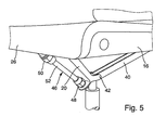
- the seat 16 is not rigidly attached to the frame 20 but also has a (not shown, usually provided in the center of the seat) hinge, wherein on the front of the frame 20, a second actuator 46 is provided.
- This second actuator 46 engages with its rear header 48 on the frame 20, wherein the front header 50 is also forked and engages a tab on the front 26 of the seat 16. If this second actuator 46 pressurized, then the diameter of the hose body 52 increases, whereas its length is shortened. As a result, the rear end of the seat 16 is raised by the hinge, not shown, on the frame 20, and the front side 26 is lowered, thereby forgetting the seat inclination.
- the backrest 18 can thus be changed in the inventive swivel chair 10 by means of the first actuator 24 in the inclination, without mechanical springs are required.
- a second actuator 46 is optionally used. It should be emphasized that both actuators 24 and 46 are independently operable and that the inclination of the seat 16 are independent of the inclination of the backrest 18 and vice versa adjustable and do not affect each other. Both actuators 24 and 46 are actuated by means of a fluid, i. pressurized by means of a gas or a liquid. This can be done manually or by machine, wherein advantageously a pressure accumulator is provided on the office chair 10. In addition, an electrically operated pump can be provided to generate the pressure.
Landscapes
- Health & Medical Sciences (AREA)
- Dentistry (AREA)
- General Health & Medical Sciences (AREA)
- Chairs Characterized By Structure (AREA)
- Chairs For Special Purposes, Such As Reclining Chairs (AREA)
Abstract
Description
- Die Erfindung betrifft einen Bürostuhl mit einem Sitz und einer Rückenlehne, wobei der Sitz auf oder an einem auf dem Boden stehendes Gestell montiert ist, und die Rückenlehne mit dem Gestell und/oder mit dem Sitz neigbar verbunden ist.
- Bürostühle mit Gestell, Sitz und Rückenlehne sind üblicherweise in der Höhe und der Neigungswinkel der Rückenlehne an unterschiedliche Benutzers anpassbar. Hierfür ist die Rückenlehne z.B. mit einem Scharniergelenk mit dem Sitz oder dem Gestell verbunden und mittels einer mechanischen Feder oder einer Gasdruckfeder derart in Richtung des Rückens des Benutzers vorgespannt, dass sie nach der Entriegelung vom Benutzer entgegen der Federkraft nach hinten gedrückt und in der gewünschten neuen Lage wieder verriegelt werden kann.
- Der Erfindung liegt die Aufgabe zugrunde, einen Bürostuhl bereit zu stellen, bei welchem die Rückenlehne nicht über den Rücken des Benutzers betätigt wird, sondern die Rückenlehne auch dann in eine gewünschte andere Position überführt werden kann, wenn sich der Benutzer nicht an ihr anlehnt.
- Diese Aufgabe wird bei einem Bürostuhl der eingangs genannten Art erfindungsgemäß dadurch gelöst, dass zusätzlich zwischen die Rückenlehne und das Gestell oder den Sitz eine durch Fluidkraft aktivierbare Betätigungsvorrichtung für die Rückenlehne zwischengeschaltet ist.
- Beim erfindungsgemäßen Bürostuhl weist die Betätigungsvorrichtung keine mechanischen Federelemente auf, die die Rückenlehne in die eine oder andere Position, d.h. in Richtung des Benutzers oder weg von diesem, drängt. Die Betätigungsvorrichtung ist rein pneumatischer und/oder hydraulischer Natur.
- Aus der
DE 299 08 008 U1 ist eine durch Fluidkraft aktivierbare Betätigungsvorrichtung bekannt, bei welcher ein Innenraum mit einem Fluid beaufschlagt werden kann. Dabei ist die Betätigungsvorrichtung schlauchartig ausgebildet und wird bei Erhöhung des Innendrucks radial vergrößert, wodurch sich deren Länge verkürzt. Auf dieser Weise kann eine axiale Hubbewegung erzeugt werden. - Aus der
EP 1 086 314 B1 ist eine ähnliche Betätigungsvorrichtung bekannt, bei welcher der Mantel des Schlauchkörpers mit einer koaxialen Strangstruktur mit zwei über Kreuz stehenden Stranggruppen ausgebildet ist. Bei Druckbeaufschlagung verkürzt sich auch bei dieser Variante der Schlauchkörper, der sich dabei radial ausdehnt. Somit können auch mit dieser Betätigungsvorrichtung ohne die Verwendung eines Kolbens Hubbewegungen ausgeführt werden. - Bei einer bevorzugten Ausführungsform der Erfindung ist die Betätigungsvorrichtung schlauchartig ausgebildet und wird durch Fluidkraft derart aktiviert, dass sie bei radialer Ausdehnung sich verkürzt. Die Integration einer derartigen Betätigungsvorrichtung in einen Bürostuhl hat den wesentlichen Vorteil, dass keine mechanischen Federn als Kraftspeicher verwendet werden müssen. Durch die Menge und Geschwindigkeit der Fluidzugabe oder -abgabe kann die Betätigungsvorrichtung zwischen ihren Endstellungen jede beliebige Zwischenstellung einnehmen, die positionsgenau erreicht werden kann. Außerdem sind beliebige Positionen der Betätigungsvorrichtung speicherbar und wieder abrufbar. Außerdem kann der Bürostuhl bei Nichtgebrauch nach einer vorgebbaren Zeit wieder in seine Ausgangslage oder Ruhelage zurückkehren.
- Mit Vorzug weist die Betätigungsvorrichtung zwei Kopfstücke auf, wobei sie an wenigstens einem ein Scharniergelenk aufweist. Mittels dieses Scharniergelenks kann die Betätigungsvorrichtung einerseits einfach am Sitz oder dem Gestell sowie an der Rückenlehne montiert werden und überträgt die Zug- und Druckkräfte biegungsfrei. Die Kopfstücke können auf einfache Weise an die Abmessungen des Bürostuhls angepasst werden.
- Bei einer Weiterbildung der Erfindung ist vorgesehen, dass wenigstens eines der Kopfstücke eine Anschlusseinrichtung für ein fluides Medium aufweist. Über die Anschlusseinrichtung kann das Fluid dem Innenraum der Betätigungsvorrichtung zugeführt oder aus diesem abgeführt werden. Ein Hydraulikfluid wird in einen Sammeltank geleitet, aus dem es dann bei Gebrauch wieder zurückgeführt werden kann. Ein pneumatisches Medium, z.B. Luft, wird in die Umgebung abgeführt und bei Bedarf aus der Umgebung der Betätigungsvorrichtung wieder zugeführt.
- Dabei ist bei einer Ausführungsform der Erfindung die Anschlusseinrichtung zum Anschluss einer manuellen Betätigungseinrichtung, insbesondere einer Luftpumpe und/oder einer Ablassvorrichtung ausgerüstet. Diese manuelle Betätigungseinrichtung kann z.B. ein Handhebel sein, der sich unterhalb des Sitzes befindet, mit dem der Innenraum der Betätigungsvorrichtung aufgeblasen oder dessen Innendruck verringert wird. Es besteht auch die Möglichkeit, dass ein Druckspeicher vorgesehen ist, der dadurch befüllt wird, dass der Benutzer den Sitz belastet.
- Alternativ ist die Anschlusseinrichtung zum Anschluss einer motorischen Einrichtung oder eines Druckschlauchs, insbesondere einer Fluidpumpe und/oder einer Ablassvorrichtung ausgerüstet. Diese Fluidpumpe wird bevorzugt elektrisch betätigt, so dass am Bürostuhl z.B. ein zusätzlicher Druckschalter vorgesehen ist, mit welchem die Fluidpumpe sowie die Ablassvorrichtung gesteuert werden.
- Erfindungsgemäß weist die Betätigungsvorrichtung einen Schlauchkörper auf, in dessen Mantel wenigstens zwei über Kreuz verlaufende und koaxial zueinander angeordnete Strangstrukturen aufweist. Diese Strangstrukturen umfassen den Schlauchkörper in beide Richtungen wendelartig und bilden quasi einen Netzschlauch der den Innenraum umgreift und dessen Form bestimmt. Die beiden Strangstrukturen verlaufen also an ihren Kreuzungsstellen scherenartig zueinander.
- Um das optische Erscheinungsbild des Bürostuhls nicht zu beeinträchtigen, befindet sich die Betätigungsvorrichtung unterhalb des Sitzes. Da die Betätigungsvorrichtung einen relativ schlanken Schlauchkörper aufweist, kann sie auch ohne Abdeckgehäuse verbaut werden, ohne dass sie optisch auffällt oder das Gesamtbild des Bürostuhls beeinträchtigt. Dabei verläuft die Betätigungsvorrichtung erfindungsgemäß in ihrer Ruhelage parallel zur Ebene des Sitzes. Mit Vorzug ist sie in den Unterbau des Sitzes integriert.
- Bei einer bevorzugten Variante der Erfindung erstreckt sich die Betätigungsvorrichtung von der Sitzvorderkante in Richtung der Rückenlehne. Eine Verkürzung oder Verlängerung der Betätigungsvorrichtung bewirkt direkt eine Kippneigung der Rückenlehne, da die Betätigungsvorrichtung unterhalb des Sitzes an die Rückenlehne angeschlossen ist, so dass die Unterkante mehr oder weniger weit von der Vorderkante des Sitzes entfernt liegt.
- Eine bevorzugte Weiterbildung der Erfindung sieht vor, dass eine zweite Betätigungsvorrichtung vorgesehen ist, die zwischen den Sitz und das Gestell zur Veränderung der Sitzneigung zwischengeschaltet ist. Diese zweite Betätigungsvorrichtung entspricht dem Aufbau der zuvor beschriebenen Betätigungsvorrichtung für die Rückenlehne, wobei sie bei einer motorischen Versorgung von der gleichen Druckquelle versorgt werden kann. Mittels der zweiten Betätigungsvorrichtung kann die Sitzneigung individuell auf unterschiedliche Benutzer eingestellt und verstellt die die Neigungslage fixiert werden.
- Weitere Vorteile, Merkmale und Einzelheiten der Erfindung ergeben sich aus der nachfolgenden Beschreibung, in der unter Bezugnahme auf die Zeichnung zwei Varianten der Erfindung beschrieben sind.
- In der Zeichnung zeigen:
- Figur 1
- eine Seitenansicht einer ersten Variante des Bürostuhls in Ruhelage;
- Figur 2
- den Bürostuhl gemäß
Figur 1 mit geneigter Rückenlehne; - Figur 3
- eine vergrößerte Wiedergabe des Ausschnitts III gemäß
Figur 1 ; - Figur 4
- eine perspektivische Ansicht in Richtung des Pfeils IV gemäß
Figur 3 unter den Sitz; und - Figur 5
- eine vergrößerte Wiedergabe eines Teilausschnitts des Sitzes gemäß einer zweiten Variante des erfindungsgemäßen Bürostuhls.
- Die
Figur 1 zeigt einen insgesamt mit 10 bezeichneten Bürostuhls gemäß einer ersten Variante der Erfindung, der ein teleskopierbares Gestell 12 mit einem Fuß-Drehkreuz 14, einen Sitz 16 und eine Rückenlehne 18 aufweist. Das Gestell 12 ist über einen Rahmen 20 sowohl mit dem Sitz 16 als auch mit der Rückenlehne 18 verbunden. Der untere Teil 22 des Rahmens 20 ist drehbar einstellbar und ggf. arretierbar am oberen Ende des Gestells 12 montiert. Ferner ist erkennbar, dass der Sitz 16 und die Rückenlehne 18 eine Polsterung oder Bespannung aufweisen. - Ferner ist erkennbar, dass unterhalb des Sitzes 16 und parallel zu dessen Ebene eine Betätigungsvorrichtung 24 vorgesehen ist, die sich von der Vorderseite 26 des Sitzes 16 in Richtung der Rückenlehne 18 erstreckt. Die Betätigungsvorrichtung 24 weist in der
Figur 1 ihre Ruhelage auf, in welcher sie eine langgestreckte Form besitzt. Die Rückenlehne 18 weist in dieser Ruhelage einen Neigungswinkel α von ca. 20° auf. - In der
Figur 2 weist die Betätigungsvorrichtung 24 eine ihrer Arbeitslagen auf, in welcher sie verkürzt ist, jedoch einen größeren Durchmesser aufweist. Die Rückenlehne 18 weist in dieser Arbeitslage einen Neigungswinkel β von ca. 10° auf. - Die Betätigungsvorrichtung 24 ist mit ihrem vorderen Ende am Rahmen 20 montiert, wohingegen das hintere Ende an der Rückenlehne 18 angreift, was im Detail in
Figur 3 dargestellt ist. Die Betätigungsvorrichtung 24 besitzt einen zentralen Schlauchkörper 28, dessen Enden von einem vorderen Kopfstück 30 und einem hinteren Kopfstück 32 gebildet werden. Das vordere Kopfstück 30 ist gabelartig ausgebildet und greift in eine Zunge 34 am Rahmen 20 und bildet dadurch ein Scharniergelenk 36. Das hintere Kopfstück 32 kann ebenfalls gabelartig ausgeführt sein und mit einer an der Rückenlehne 18 vorgesehenen Lasche verbunden sein. Beim dargestellten Ausführungsbeispiel besitzt das hintere Kopfstück 32 einen axial abragenden Gewindebolzen, der in eine entsprechende Gewindeöffnung an der Rückenlehne 18 eingeschraubt ist. Hierfür weist das hintere Kopfstück 32 einen Sechskant 38 auf, an welchem ein geeignetes Werkzeug, z.B. ein Maulschlüssel, angesetzt werden kann. Die Rückenlehne 18 erstreckt sich oberhalb des Sitzes 16 und weist unterhalb des Sitzes 16 ein Traggerüst 40 auf, welches mittels eines Scharniers 42 schwenkbar am Rahmen 20 befestigt ist. Ferner ist erkennbar, dass im Übergang von Traggerüst 40 und Bespannung der Rückenlehne 18 ein Knie 43 ausgebildet ist, welches die hintere, unterhalb der Rückenlehne 18 sich befindende Kante 45 des Sitzes 16 umgeht. - In der
Figur 4 ist der Übergang vom Rahmen 20 in den Sitz 16 erkennbar, wobei das Scharniergelenk 36 an einer Querstrebe 44 sitzt. Bei einer Druckbeaufschlagung des Schlauchkörpers 28 der Betätigungsvorrichtung 24 vergrößert sich deren Durchmesser, wobei sich die Länge verkürzt. Hierdurch wird das Traggerüst 40 der Rückenlehne 18 am Scharnier 42 entgegen des Uhrzeigersinns verschwenkt, wodurch das Knie 43 nach oben vorne verlagert wird. Entsprechend neigt sich die Rückenlehne 18 nach vorne. Wird der Druck in der Betätigungsvorrichtung 24 abgelassen, verkleinert sich der Durchmesser des Schlauchkörpers 28, wodurch sich die Länge vergrößert und die Rückenlehne 18 sich nach hinten neigt. - Beim in der
Figur 5 dargestellten Ausführungsbeispiel ist der Sitz 16 nicht starr am Rahmen 20 befestigt sondern weist ebenfalls ein (nicht dargestelltes, üblicherweise in der Sitzmitte vorgesehenes) Scharnier aus, wobei an der Vorderseite des Rahmens 20 eine zweite Betätigungsvorrichtung 46 vorgesehen ist. Diese zweite Betätigungsvorrichtung 46 greift mit ihrem hinteren Kopfstück 48 am Rahmen 20 an, wobei das vordere Kopfstück 50 ebenfalls gabelförmig ausgebildet ist und an einer Lasche an der Vorderseite 26 des Sitzes 16 angreift. Wird diese zweite Betätigungsvorrichtung 46 mit Druck beaufschlagt, dann vergrößert sich der Durchmesser dessen Schlauchkörpers 52, wohingegen sich dessen Länge verkürzt. Dadurch wird das hintere Ende des Sitzes 16 um das nicht gezeigte Scharnier am Rahmen 20 angehoben, bzw. die Vorderseite 26 abgesenkt und dadurch die Sitzneigung vergstellt. - Die Rückenlehne 18 kann also beim erfindungsgemäßen Drehstuhl 10 mittels der ersten Betätigungsvorrichtung 24 in der Neigung verändert werden, ohne dass mechanische Federn erforderlich sind. Zur Änderung der Neigung des Sitzes 16 wird optional eine zweite Betätigungsvorrichtung 46 verwendet. Hervorzuheben ist, dass beide Betätigungsvorrichtungen 24 und 46 unabhängig voneinander betätigbar sind und dass die Neigung des Sitzes 16 unabhängig von der Neigung der Rückenlehne 18 und umgekehrt einstellbar sind und sich gegenseitig nicht beeinflussen. Beide Betätigungsvorrichtungen 24 und 46 werden mittels eines Fluids, d.h. mittels eines Gases oder einer Flüssigkeit mit Druck beaufschlagt. Dies kann manuell oder maschinell erfolgen, wobei vorteilhaft ein Druckspeicher am Bürostuhl 10 vorgesehen ist. Zur Erzeugung des Drucks kann zudem eine elektrisch betriebene Pumpe vorgesehen sein.
Claims (12)
- Bürostuhl (10) mit einem Sitz (16) und einer Rückenlehne (18), wobei der Sitz (16) auf oder an einem auf dem Boden stehendes Gestell (21) montiert ist, und die Rückenlehne (18) mit dem Gestell (12) und/oder mit dem Sitz (16) neigbar verbunden ist, dadurch gekennzeichnet, dass zusätzlich zwischen die Rückenlehne (18) und das Gestell (12) oder den Sitz (16) eine durch Fluidkraft aktivierbare Betätigungsvorrichtung (24) für die Rückenlehne (18) zwischengeschaltet ist.
- Bürostuhl nach Anspruch 1, dadurch gekennzeichnet, dass die Betätigungsvorrichtung (24) schlauchartig ausgebildet ist und durch Fluidkraft derart aktivierbar ist, dass sie sich bei radialer Aufweitung verkürzt.
- Bürostuhl nach einem der vorhergehenden Ansprüche, dadurch gekennzeichnet, dass die Betätigungsvorrichtung (24) zwei Kopfstücke (30, 32) aufweist, wobei sie an wenigstens einem ein Scharniergelenk (36) aufweist.
- Bürostuhl nach einem der vorhergehenden Ansprüche, dadurch gekennzeichnet, dass wenigstens einer der Kopfstücke (30 oder 32) eine Anschlusseinrichtung für ein fluides Druckmedium aufweist.
- Bürostuhl nach Anspruch 4, dadurch gekennzeichnet, dass die Anschlusseinrichtung zum Anschluss einer manuellen Betätigungseinrichtung, insbesondere einer Fluidpumpe und/oder einer Ablassvorrichtung ausgerüstet ist.
- Bürostuhl nach Anspruch 4, dadurch gekennzeichnet, dass die Anschlusseinrichtung zum Anschluss einer motorischen Einrichtung oder eines Druckschlauchs, insbesondere einer Fluidpumpe und/oder einer Ablassvorrichtung ausgerüstet ist.
- Bürostuhl nach einem der vorhergehenden Ansprüche, dadurch gekennzeichnet, dass die Betätigungsvorrichtung (24) einen Schlauchkörper (28) aufweist, dessen Mantel wenigstens zwei über Kreuz verlaufende und koaxial zueinander angeordnete Strangstrukturen aufweist.
- Bürostuhl nach einem der vorhergehenden Ansprüche, dadurch gekennzeichnet, dass die Betätigungsvorrichtung (24) sich unterhalb des Sitzes (16) befindet.
- Bürostuhl nach einem der vorhergehenden Ansprüche, dadurch gekennzeichnet, dass die Betätigungsvorrichtung (24) in der Ruhelage parallel zur Ebene des Sitzes (16) verläuft.
- Bürostuhl nach einem der vorhergehenden Ansprüche, dadurch gekennzeichnet, dass die Betätigungsvorrichtung (24) von der Sitzvorderseite (26) sich in Richtung der Rückenlehne (18) erstreckt.
- Bürostuhl nach einem der vorhergehenden Ansprüche, dadurch gekennzeichnet, dass eine zweite Betätigungsvorrichtung (46) vorgesehen ist, die zwischen den Sitz (16) und das Gestell (12) zur Veränderung der Sitzneigung (Winkel α und β)zwischengeschaltet ist.
- Bürostuhl nach einem der vorhergehenden Ansprüche, dadurch gekennzeichnet, dass der Sitz (16) über ein Scharniergelenk mit dem Gestell (12) verbunden ist.
Priority Applications (1)
| Application Number | Priority Date | Filing Date | Title |
|---|---|---|---|
| EP15001155.9A EP3085272B1 (de) | 2015-04-20 | 2015-04-20 | Bürostuhl |
Applications Claiming Priority (1)
| Application Number | Priority Date | Filing Date | Title |
|---|---|---|---|
| EP15001155.9A EP3085272B1 (de) | 2015-04-20 | 2015-04-20 | Bürostuhl |
Publications (2)
| Publication Number | Publication Date |
|---|---|
| EP3085272A1 true EP3085272A1 (de) | 2016-10-26 |
| EP3085272B1 EP3085272B1 (de) | 2017-08-02 |
Family
ID=52991434
Family Applications (1)
| Application Number | Title | Priority Date | Filing Date |
|---|---|---|---|
| EP15001155.9A Not-in-force EP3085272B1 (de) | 2015-04-20 | 2015-04-20 | Bürostuhl |
Country Status (1)
| Country | Link |
|---|---|
| EP (1) | EP3085272B1 (de) |
Citations (4)
| Publication number | Priority date | Publication date | Assignee | Title |
|---|---|---|---|---|
| US4966413A (en) * | 1989-08-17 | 1990-10-30 | Palarski Timothy D | Articulated relaxation chair |
| DE29908008U1 (de) | 1999-05-05 | 1999-07-22 | Festo AG & Co, 73734 Esslingen | Betätigungseinrichtung |
| EP1086314B1 (de) | 1999-04-14 | 2005-01-12 | FESTO AG & Co | Betätigungseinrichtung |
| US20100066132A1 (en) * | 2008-09-17 | 2010-03-18 | Rafael Tal Marchand | Adjustable workstation |
-
2015
- 2015-04-20 EP EP15001155.9A patent/EP3085272B1/de not_active Not-in-force
Patent Citations (4)
| Publication number | Priority date | Publication date | Assignee | Title |
|---|---|---|---|---|
| US4966413A (en) * | 1989-08-17 | 1990-10-30 | Palarski Timothy D | Articulated relaxation chair |
| EP1086314B1 (de) | 1999-04-14 | 2005-01-12 | FESTO AG & Co | Betätigungseinrichtung |
| DE29908008U1 (de) | 1999-05-05 | 1999-07-22 | Festo AG & Co, 73734 Esslingen | Betätigungseinrichtung |
| US20100066132A1 (en) * | 2008-09-17 | 2010-03-18 | Rafael Tal Marchand | Adjustable workstation |
Also Published As
| Publication number | Publication date |
|---|---|
| EP3085272B1 (de) | 2017-08-02 |
Similar Documents
| Publication | Publication Date | Title |
|---|---|---|
| DE102016108420B4 (de) | Hydraulisches Werkzeug | |
| EP1853455B1 (de) | Sitz | |
| EP2403761B1 (de) | Fluggastsitzvorrichtung | |
| DE2940250A1 (de) | Ergonomischer stuhl | |
| EP2374371A1 (de) | Sitzmöbel mit einem in eine Aufstehhilfsposition schwenkbaren Sitz | |
| EP2571720A2 (de) | Verstellvorrichtung für kraftfahrzeugsitze, insbesondere höhenverstellvorrichtungen | |
| DE19945118A1 (de) | Sessel mit Aufstehhilfe | |
| EP2638827A1 (de) | Schwenkbeschlag zum Verstellen eines Polstermöbels | |
| DE102006047403B4 (de) | Rückenlehnenmechanismus für eine Bedienerplattform eines Industriefahrzeugs, das ein Fahrer im Stehen bedienen kann | |
| EP1632152A2 (de) | Sitzmöbel | |
| EP3085272B1 (de) | Bürostuhl | |
| EP2172136B1 (de) | Sitzmöbel mit Sitzteil und Rückenteil | |
| DE3425622C1 (de) | Hoeheneinstellbares Podest fuer Buehnen o.dgl. | |
| EP3146868B1 (de) | Multifunktionsmöbel | |
| DE19953481A1 (de) | Sicherheitseinrichtung für ein Kraftfahrzeug mit einer Fussablage | |
| DE202017104400U1 (de) | Sitz- und/oder Liegemöbel | |
| DE202006010395U1 (de) | Sitzmöbel oder Sitz-Liegemöbel | |
| DE202018100807U1 (de) | Sitz- und Stützmöbel | |
| EP2245964B1 (de) | Sitzmöbel mit einem eine Rückenlehne und ein Fußteil verbindenden Koppelgestänge | |
| DE102017117655A1 (de) | Zweiradständer | |
| DE2810632B2 (de) | Trimmgerät | |
| DE102005042264B3 (de) | Schneidvorrichtung | |
| DE202014100062U1 (de) | Sitzmöbel mit federnder Rückenlehne | |
| DE19833402C2 (de) | Schalensitz für Fahrzeuge | |
| EP1972315B1 (de) | Sessel mit Aufstehhilfe |
Legal Events
| Date | Code | Title | Description |
|---|---|---|---|
| PUAI | Public reference made under article 153(3) epc to a published international application that has entered the european phase |
Free format text: ORIGINAL CODE: 0009012 |
|
| 17P | Request for examination filed |
Effective date: 20160220 |
|
| AK | Designated contracting states |
Kind code of ref document: A1 Designated state(s): AL AT BE BG CH CY CZ DE DK EE ES FI FR GB GR HR HU IE IS IT LI LT LU LV MC MK MT NL NO PL PT RO RS SE SI SK SM TR |
|
| AX | Request for extension of the european patent |
Extension state: BA ME |
|
| GRAP | Despatch of communication of intention to grant a patent |
Free format text: ORIGINAL CODE: EPIDOSNIGR1 |
|
| INTG | Intention to grant announced |
Effective date: 20170314 |
|
| GRAS | Grant fee paid |
Free format text: ORIGINAL CODE: EPIDOSNIGR3 |
|
| GRAA | (expected) grant |
Free format text: ORIGINAL CODE: 0009210 |
|
| AK | Designated contracting states |
Kind code of ref document: B1 Designated state(s): AL AT BE BG CH CY CZ DE DK EE ES FI FR GB GR HR HU IE IS IT LI LT LU LV MC MK MT NL NO PL PT RO RS SE SI SK SM TR |
|
| REG | Reference to a national code |
Ref country code: CH Ref legal event code: EP Ref country code: AT Ref legal event code: REF Ref document number: 913493 Country of ref document: AT Kind code of ref document: T Effective date: 20170815 |
|
| REG | Reference to a national code |
Ref country code: IE Ref legal event code: FG4D Free format text: LANGUAGE OF EP DOCUMENT: GERMAN |
|
| REG | Reference to a national code |
Ref country code: DE Ref legal event code: R096 Ref document number: 502015001519 Country of ref document: DE |
|
| REG | Reference to a national code |
Ref country code: NL Ref legal event code: MP Effective date: 20170802 |
|
| REG | Reference to a national code |
Ref country code: LT Ref legal event code: MG4D |
|
| PG25 | Lapsed in a contracting state [announced via postgrant information from national office to epo] |
Ref country code: FI Free format text: LAPSE BECAUSE OF FAILURE TO SUBMIT A TRANSLATION OF THE DESCRIPTION OR TO PAY THE FEE WITHIN THE PRESCRIBED TIME-LIMIT Effective date: 20170802 Ref country code: SE Free format text: LAPSE BECAUSE OF FAILURE TO SUBMIT A TRANSLATION OF THE DESCRIPTION OR TO PAY THE FEE WITHIN THE PRESCRIBED TIME-LIMIT Effective date: 20170802 Ref country code: LT Free format text: LAPSE BECAUSE OF FAILURE TO SUBMIT A TRANSLATION OF THE DESCRIPTION OR TO PAY THE FEE WITHIN THE PRESCRIBED TIME-LIMIT Effective date: 20170802 Ref country code: NL Free format text: LAPSE BECAUSE OF FAILURE TO SUBMIT A TRANSLATION OF THE DESCRIPTION OR TO PAY THE FEE WITHIN THE PRESCRIBED TIME-LIMIT Effective date: 20170802 Ref country code: NO Free format text: LAPSE BECAUSE OF FAILURE TO SUBMIT A TRANSLATION OF THE DESCRIPTION OR TO PAY THE FEE WITHIN THE PRESCRIBED TIME-LIMIT Effective date: 20171102 Ref country code: HR Free format text: LAPSE BECAUSE OF FAILURE TO SUBMIT A TRANSLATION OF THE DESCRIPTION OR TO PAY THE FEE WITHIN THE PRESCRIBED TIME-LIMIT Effective date: 20170802 |
|
| PG25 | Lapsed in a contracting state [announced via postgrant information from national office to epo] |
Ref country code: BG Free format text: LAPSE BECAUSE OF FAILURE TO SUBMIT A TRANSLATION OF THE DESCRIPTION OR TO PAY THE FEE WITHIN THE PRESCRIBED TIME-LIMIT Effective date: 20171102 Ref country code: LV Free format text: LAPSE BECAUSE OF FAILURE TO SUBMIT A TRANSLATION OF THE DESCRIPTION OR TO PAY THE FEE WITHIN THE PRESCRIBED TIME-LIMIT Effective date: 20170802 Ref country code: PL Free format text: LAPSE BECAUSE OF FAILURE TO SUBMIT A TRANSLATION OF THE DESCRIPTION OR TO PAY THE FEE WITHIN THE PRESCRIBED TIME-LIMIT Effective date: 20170802 Ref country code: RS Free format text: LAPSE BECAUSE OF FAILURE TO SUBMIT A TRANSLATION OF THE DESCRIPTION OR TO PAY THE FEE WITHIN THE PRESCRIBED TIME-LIMIT Effective date: 20170802 Ref country code: GR Free format text: LAPSE BECAUSE OF FAILURE TO SUBMIT A TRANSLATION OF THE DESCRIPTION OR TO PAY THE FEE WITHIN THE PRESCRIBED TIME-LIMIT Effective date: 20171103 Ref country code: IS Free format text: LAPSE BECAUSE OF FAILURE TO SUBMIT A TRANSLATION OF THE DESCRIPTION OR TO PAY THE FEE WITHIN THE PRESCRIBED TIME-LIMIT Effective date: 20171202 Ref country code: ES Free format text: LAPSE BECAUSE OF FAILURE TO SUBMIT A TRANSLATION OF THE DESCRIPTION OR TO PAY THE FEE WITHIN THE PRESCRIBED TIME-LIMIT Effective date: 20170802 |
|
| REG | Reference to a national code |
Ref country code: FR Ref legal event code: PLFP Year of fee payment: 4 |
|
| PG25 | Lapsed in a contracting state [announced via postgrant information from national office to epo] |
Ref country code: DK Free format text: LAPSE BECAUSE OF FAILURE TO SUBMIT A TRANSLATION OF THE DESCRIPTION OR TO PAY THE FEE WITHIN THE PRESCRIBED TIME-LIMIT Effective date: 20170802 Ref country code: CZ Free format text: LAPSE BECAUSE OF FAILURE TO SUBMIT A TRANSLATION OF THE DESCRIPTION OR TO PAY THE FEE WITHIN THE PRESCRIBED TIME-LIMIT Effective date: 20170802 |
|
| REG | Reference to a national code |
Ref country code: DE Ref legal event code: R097 Ref document number: 502015001519 Country of ref document: DE |
|
| PG25 | Lapsed in a contracting state [announced via postgrant information from national office to epo] |
Ref country code: EE Free format text: LAPSE BECAUSE OF FAILURE TO SUBMIT A TRANSLATION OF THE DESCRIPTION OR TO PAY THE FEE WITHIN THE PRESCRIBED TIME-LIMIT Effective date: 20170802 Ref country code: SK Free format text: LAPSE BECAUSE OF FAILURE TO SUBMIT A TRANSLATION OF THE DESCRIPTION OR TO PAY THE FEE WITHIN THE PRESCRIBED TIME-LIMIT Effective date: 20170802 Ref country code: SM Free format text: LAPSE BECAUSE OF FAILURE TO SUBMIT A TRANSLATION OF THE DESCRIPTION OR TO PAY THE FEE WITHIN THE PRESCRIBED TIME-LIMIT Effective date: 20170802 |
|
| PLBE | No opposition filed within time limit |
Free format text: ORIGINAL CODE: 0009261 |
|
| STAA | Information on the status of an ep patent application or granted ep patent |
Free format text: STATUS: NO OPPOSITION FILED WITHIN TIME LIMIT |
|
| 26N | No opposition filed |
Effective date: 20180503 |
|
| PG25 | Lapsed in a contracting state [announced via postgrant information from national office to epo] |
Ref country code: SI Free format text: LAPSE BECAUSE OF FAILURE TO SUBMIT A TRANSLATION OF THE DESCRIPTION OR TO PAY THE FEE WITHIN THE PRESCRIBED TIME-LIMIT Effective date: 20170802 |
|
| PG25 | Lapsed in a contracting state [announced via postgrant information from national office to epo] |
Ref country code: MT Free format text: LAPSE BECAUSE OF FAILURE TO SUBMIT A TRANSLATION OF THE DESCRIPTION OR TO PAY THE FEE WITHIN THE PRESCRIBED TIME-LIMIT Effective date: 20170802 |
|
| PG25 | Lapsed in a contracting state [announced via postgrant information from national office to epo] |
Ref country code: MC Free format text: LAPSE BECAUSE OF FAILURE TO SUBMIT A TRANSLATION OF THE DESCRIPTION OR TO PAY THE FEE WITHIN THE PRESCRIBED TIME-LIMIT Effective date: 20170802 |
|
| REG | Reference to a national code |
Ref country code: CH Ref legal event code: PL |
|
| REG | Reference to a national code |
Ref country code: BE Ref legal event code: MM Effective date: 20180430 |
|
| REG | Reference to a national code |
Ref country code: IE Ref legal event code: MM4A |
|
| PG25 | Lapsed in a contracting state [announced via postgrant information from national office to epo] |
Ref country code: LU Free format text: LAPSE BECAUSE OF NON-PAYMENT OF DUE FEES Effective date: 20180420 |
|
| PG25 | Lapsed in a contracting state [announced via postgrant information from national office to epo] |
Ref country code: CH Free format text: LAPSE BECAUSE OF NON-PAYMENT OF DUE FEES Effective date: 20180430 Ref country code: BE Free format text: LAPSE BECAUSE OF NON-PAYMENT OF DUE FEES Effective date: 20180430 Ref country code: LI Free format text: LAPSE BECAUSE OF NON-PAYMENT OF DUE FEES Effective date: 20180430 |
|
| PG25 | Lapsed in a contracting state [announced via postgrant information from national office to epo] |
Ref country code: IE Free format text: LAPSE BECAUSE OF NON-PAYMENT OF DUE FEES Effective date: 20180420 |
|
| REG | Reference to a national code |
Ref country code: DE Ref legal event code: R082 Ref document number: 502015001519 Country of ref document: DE Representative=s name: PATENTANWAELTE MAGENBAUER & KOLLEGEN PARTNERSC, DE Ref country code: DE Ref legal event code: R081 Ref document number: 502015001519 Country of ref document: DE Owner name: FESTO SE & CO. KG, DE Free format text: FORMER OWNER: FESTO AG & CO. KG, 73734 ESSLINGEN, DE Ref country code: DE Ref legal event code: R081 Ref document number: 502015001519 Country of ref document: DE Owner name: FESTO AG & CO. KG, DE Free format text: FORMER OWNER: FESTO AG & CO. KG, 73734 ESSLINGEN, DE |
|
| PG25 | Lapsed in a contracting state [announced via postgrant information from national office to epo] |
Ref country code: TR Free format text: LAPSE BECAUSE OF FAILURE TO SUBMIT A TRANSLATION OF THE DESCRIPTION OR TO PAY THE FEE WITHIN THE PRESCRIBED TIME-LIMIT Effective date: 20170802 |
|
| PG25 | Lapsed in a contracting state [announced via postgrant information from national office to epo] |
Ref country code: PT Free format text: LAPSE BECAUSE OF FAILURE TO SUBMIT A TRANSLATION OF THE DESCRIPTION OR TO PAY THE FEE WITHIN THE PRESCRIBED TIME-LIMIT Effective date: 20170802 |
|
| PG25 | Lapsed in a contracting state [announced via postgrant information from national office to epo] |
Ref country code: CY Free format text: LAPSE BECAUSE OF FAILURE TO SUBMIT A TRANSLATION OF THE DESCRIPTION OR TO PAY THE FEE WITHIN THE PRESCRIBED TIME-LIMIT Effective date: 20170802 Ref country code: HU Free format text: LAPSE BECAUSE OF FAILURE TO SUBMIT A TRANSLATION OF THE DESCRIPTION OR TO PAY THE FEE WITHIN THE PRESCRIBED TIME-LIMIT; INVALID AB INITIO Effective date: 20150420 Ref country code: RO Free format text: LAPSE BECAUSE OF FAILURE TO SUBMIT A TRANSLATION OF THE DESCRIPTION OR TO PAY THE FEE WITHIN THE PRESCRIBED TIME-LIMIT Effective date: 20170802 Ref country code: MK Free format text: LAPSE BECAUSE OF NON-PAYMENT OF DUE FEES Effective date: 20170802 |
|
| PG25 | Lapsed in a contracting state [announced via postgrant information from national office to epo] |
Ref country code: AL Free format text: LAPSE BECAUSE OF FAILURE TO SUBMIT A TRANSLATION OF THE DESCRIPTION OR TO PAY THE FEE WITHIN THE PRESCRIBED TIME-LIMIT Effective date: 20170802 |
|
| REG | Reference to a national code |
Ref country code: AT Ref legal event code: MM01 Ref document number: 913493 Country of ref document: AT Kind code of ref document: T Effective date: 20200420 |
|
| PG25 | Lapsed in a contracting state [announced via postgrant information from national office to epo] |
Ref country code: AT Free format text: LAPSE BECAUSE OF NON-PAYMENT OF DUE FEES Effective date: 20200420 |
|
| PGFP | Annual fee paid to national office [announced via postgrant information from national office to epo] |
Ref country code: IT Payment date: 20230428 Year of fee payment: 9 Ref country code: FR Payment date: 20230417 Year of fee payment: 9 Ref country code: DE Payment date: 20220622 Year of fee payment: 9 |
|
| P01 | Opt-out of the competence of the unified patent court (upc) registered |
Effective date: 20230623 |
|
| PGFP | Annual fee paid to national office [announced via postgrant information from national office to epo] |
Ref country code: GB Payment date: 20230420 Year of fee payment: 9 |
|
| REG | Reference to a national code |
Ref country code: DE Ref legal event code: R119 Ref document number: 502015001519 Country of ref document: DE |
|
| GBPC | Gb: european patent ceased through non-payment of renewal fee |
Effective date: 20240420 |
|
| PG25 | Lapsed in a contracting state [announced via postgrant information from national office to epo] |
Ref country code: DE Free format text: LAPSE BECAUSE OF NON-PAYMENT OF DUE FEES Effective date: 20241105 |
|
| PG25 | Lapsed in a contracting state [announced via postgrant information from national office to epo] |
Ref country code: GB Free format text: LAPSE BECAUSE OF NON-PAYMENT OF DUE FEES Effective date: 20240420 |
|
| PG25 | Lapsed in a contracting state [announced via postgrant information from national office to epo] |
Ref country code: FR Free format text: LAPSE BECAUSE OF NON-PAYMENT OF DUE FEES Effective date: 20240430 |
|
| PG25 | Lapsed in a contracting state [announced via postgrant information from national office to epo] |
Ref country code: GB Free format text: LAPSE BECAUSE OF NON-PAYMENT OF DUE FEES Effective date: 20240420 Ref country code: FR Free format text: LAPSE BECAUSE OF NON-PAYMENT OF DUE FEES Effective date: 20240430 Ref country code: DE Free format text: LAPSE BECAUSE OF NON-PAYMENT OF DUE FEES Effective date: 20241105 |
|
| PG25 | Lapsed in a contracting state [announced via postgrant information from national office to epo] |
Ref country code: IT Free format text: LAPSE BECAUSE OF NON-PAYMENT OF DUE FEES Effective date: 20240420 |