EP3085199B1 - Heatable pane with high frequency transmission - Google Patents
Heatable pane with high frequency transmission Download PDFInfo
- Publication number
- EP3085199B1 EP3085199B1 EP14808607.7A EP14808607A EP3085199B1 EP 3085199 B1 EP3085199 B1 EP 3085199B1 EP 14808607 A EP14808607 A EP 14808607A EP 3085199 B1 EP3085199 B1 EP 3085199B1
- Authority
- EP
- European Patent Office
- Prior art keywords
- pane
- transparent
- electrically conductive
- disc
- conductive coating
- Prior art date
- Legal status (The legal status is an assumption and is not a legal conclusion. Google has not performed a legal analysis and makes no representation as to the accuracy of the status listed.)
- Active
Links
- 230000005540 biological transmission Effects 0.000 title claims description 44
- 239000012799 electrically-conductive coating Substances 0.000 claims description 73
- 230000005670 electromagnetic radiation Effects 0.000 claims description 29
- 238000010438 heat treatment Methods 0.000 claims description 18
- 239000011521 glass Substances 0.000 claims description 11
- -1 polyethylene Polymers 0.000 claims description 10
- XOLBLPGZBRYERU-UHFFFAOYSA-N tin dioxide Chemical compound O=[Sn]=O XOLBLPGZBRYERU-UHFFFAOYSA-N 0.000 claims description 9
- BQCADISMDOOEFD-UHFFFAOYSA-N Silver Chemical compound [Ag] BQCADISMDOOEFD-UHFFFAOYSA-N 0.000 claims description 8
- 229910052751 metal Inorganic materials 0.000 claims description 8
- 239000002184 metal Substances 0.000 claims description 8
- 229910052709 silver Inorganic materials 0.000 claims description 8
- 239000004332 silver Substances 0.000 claims description 8
- 238000004519 manufacturing process Methods 0.000 claims description 7
- XLOMVQKBTHCTTD-UHFFFAOYSA-N Zinc monoxide Chemical compound [Zn]=O XLOMVQKBTHCTTD-UHFFFAOYSA-N 0.000 claims description 6
- 229910044991 metal oxide Inorganic materials 0.000 claims description 5
- 150000004706 metal oxides Chemical class 0.000 claims description 5
- 229910001887 tin oxide Inorganic materials 0.000 claims description 5
- HZNVUJQVZSTENZ-UHFFFAOYSA-N 2,3-dichloro-5,6-dicyano-1,4-benzoquinone Chemical compound ClC1=C(Cl)C(=O)C(C#N)=C(C#N)C1=O HZNVUJQVZSTENZ-UHFFFAOYSA-N 0.000 claims description 4
- PXHVJJICTQNCMI-UHFFFAOYSA-N Nickel Chemical compound [Ni] PXHVJJICTQNCMI-UHFFFAOYSA-N 0.000 claims description 4
- KDLHZDBZIXYQEI-UHFFFAOYSA-N Palladium Chemical compound [Pd] KDLHZDBZIXYQEI-UHFFFAOYSA-N 0.000 claims description 4
- VYPSYNLAJGMNEJ-UHFFFAOYSA-N Silicium dioxide Chemical compound O=[Si]=O VYPSYNLAJGMNEJ-UHFFFAOYSA-N 0.000 claims description 4
- 239000005329 float glass Substances 0.000 claims description 4
- 239000000203 mixture Substances 0.000 claims description 4
- 230000000737 periodic effect Effects 0.000 claims description 4
- 229920003229 poly(methyl methacrylate) Polymers 0.000 claims description 4
- 239000004926 polymethyl methacrylate Substances 0.000 claims description 4
- 239000004698 Polyethylene Substances 0.000 claims description 3
- RTAQQCXQSZGOHL-UHFFFAOYSA-N Titanium Chemical compound [Ti] RTAQQCXQSZGOHL-UHFFFAOYSA-N 0.000 claims description 3
- 229910045601 alloy Inorganic materials 0.000 claims description 3
- 239000000956 alloy Substances 0.000 claims description 3
- 229910003437 indium oxide Inorganic materials 0.000 claims description 3
- PJXISJQVUVHSOJ-UHFFFAOYSA-N indium(iii) oxide Chemical compound [O-2].[O-2].[O-2].[In+3].[In+3] PJXISJQVUVHSOJ-UHFFFAOYSA-N 0.000 claims description 3
- 229910052758 niobium Inorganic materials 0.000 claims description 3
- 239000010955 niobium Substances 0.000 claims description 3
- GUCVJGMIXFAOAE-UHFFFAOYSA-N niobium atom Chemical compound [Nb] GUCVJGMIXFAOAE-UHFFFAOYSA-N 0.000 claims description 3
- 239000004417 polycarbonate Substances 0.000 claims description 3
- 229920000515 polycarbonate Polymers 0.000 claims description 3
- 229920000642 polymer Polymers 0.000 claims description 3
- 239000010936 titanium Substances 0.000 claims description 3
- 229910052719 titanium Inorganic materials 0.000 claims description 3
- 239000011787 zinc oxide Substances 0.000 claims description 3
- OKTJSMMVPCPJKN-UHFFFAOYSA-N Carbon Chemical compound [C] OKTJSMMVPCPJKN-UHFFFAOYSA-N 0.000 claims description 2
- VYZAMTAEIAYCRO-UHFFFAOYSA-N Chromium Chemical compound [Cr] VYZAMTAEIAYCRO-UHFFFAOYSA-N 0.000 claims description 2
- RYGMFSIKBFXOCR-UHFFFAOYSA-N Copper Chemical compound [Cu] RYGMFSIKBFXOCR-UHFFFAOYSA-N 0.000 claims description 2
- 239000004743 Polypropylene Substances 0.000 claims description 2
- XUIMIQQOPSSXEZ-UHFFFAOYSA-N Silicon Chemical compound [Si] XUIMIQQOPSSXEZ-UHFFFAOYSA-N 0.000 claims description 2
- ATJFFYVFTNAWJD-UHFFFAOYSA-N Tin Chemical compound [Sn] ATJFFYVFTNAWJD-UHFFFAOYSA-N 0.000 claims description 2
- HCHKCACWOHOZIP-UHFFFAOYSA-N Zinc Chemical compound [Zn] HCHKCACWOHOZIP-UHFFFAOYSA-N 0.000 claims description 2
- 229910052782 aluminium Inorganic materials 0.000 claims description 2
- XAGFODPZIPBFFR-UHFFFAOYSA-N aluminium Chemical compound [Al] XAGFODPZIPBFFR-UHFFFAOYSA-N 0.000 claims description 2
- 239000005388 borosilicate glass Substances 0.000 claims description 2
- 229910052793 cadmium Inorganic materials 0.000 claims description 2
- BDOSMKKIYDKNTQ-UHFFFAOYSA-N cadmium atom Chemical compound [Cd] BDOSMKKIYDKNTQ-UHFFFAOYSA-N 0.000 claims description 2
- 239000002041 carbon nanotube Substances 0.000 claims description 2
- 229910021393 carbon nanotube Inorganic materials 0.000 claims description 2
- 229910052804 chromium Inorganic materials 0.000 claims description 2
- 239000011651 chromium Substances 0.000 claims description 2
- 229920001940 conductive polymer Polymers 0.000 claims description 2
- 229920001577 copolymer Polymers 0.000 claims description 2
- 229910052802 copper Inorganic materials 0.000 claims description 2
- 239000010949 copper Substances 0.000 claims description 2
- 239000005357 flat glass Substances 0.000 claims description 2
- PCHJSUWPFVWCPO-UHFFFAOYSA-N gold Chemical compound [Au] PCHJSUWPFVWCPO-UHFFFAOYSA-N 0.000 claims description 2
- 229910052737 gold Inorganic materials 0.000 claims description 2
- 239000010931 gold Substances 0.000 claims description 2
- 229910052759 nickel Inorganic materials 0.000 claims description 2
- 229910052763 palladium Inorganic materials 0.000 claims description 2
- 229920001467 poly(styrenesulfonates) Polymers 0.000 claims description 2
- 229920000573 polyethylene Polymers 0.000 claims description 2
- 229920001155 polypropylene Polymers 0.000 claims description 2
- 229960002796 polystyrene sulfonate Drugs 0.000 claims description 2
- 239000011970 polystyrene sulfonate Substances 0.000 claims description 2
- 229910052710 silicon Inorganic materials 0.000 claims description 2
- 239000010703 silicon Substances 0.000 claims description 2
- 239000005361 soda-lime glass Substances 0.000 claims description 2
- 239000011135 tin Substances 0.000 claims description 2
- 229910052718 tin Inorganic materials 0.000 claims description 2
- WFKWXMTUELFFGS-UHFFFAOYSA-N tungsten Chemical compound [W] WFKWXMTUELFFGS-UHFFFAOYSA-N 0.000 claims description 2
- 229910052721 tungsten Inorganic materials 0.000 claims description 2
- 239000010937 tungsten Substances 0.000 claims description 2
- XLYOFNOQVPJJNP-UHFFFAOYSA-N water Substances O XLYOFNOQVPJJNP-UHFFFAOYSA-N 0.000 claims description 2
- 229910052725 zinc Inorganic materials 0.000 claims description 2
- 239000011701 zinc Substances 0.000 claims description 2
- 238000000059 patterning Methods 0.000 claims 1
- 239000010410 layer Substances 0.000 description 56
- 239000002131 composite material Substances 0.000 description 30
- 238000000034 method Methods 0.000 description 27
- 238000000576 coating method Methods 0.000 description 26
- 239000011248 coating agent Substances 0.000 description 14
- 238000004891 communication Methods 0.000 description 10
- 229920000139 polyethylene terephthalate Polymers 0.000 description 10
- 239000005020 polyethylene terephthalate Substances 0.000 description 10
- 229920001169 thermoplastic Polymers 0.000 description 10
- 239000004416 thermosoftening plastic Substances 0.000 description 10
- 230000008569 process Effects 0.000 description 9
- 229920003023 plastic Polymers 0.000 description 8
- 239000004033 plastic Substances 0.000 description 8
- 229920002037 poly(vinyl butyral) polymer Polymers 0.000 description 8
- 230000008901 benefit Effects 0.000 description 5
- 239000000463 material Substances 0.000 description 5
- 230000005855 radiation Effects 0.000 description 5
- 239000000853 adhesive Substances 0.000 description 4
- 230000001070 adhesive effect Effects 0.000 description 4
- 230000035699 permeability Effects 0.000 description 4
- 238000004088 simulation Methods 0.000 description 4
- 230000007704 transition Effects 0.000 description 4
- 239000004952 Polyamide Substances 0.000 description 3
- 239000005038 ethylene vinyl acetate Substances 0.000 description 3
- AMGQUBHHOARCQH-UHFFFAOYSA-N indium;oxotin Chemical compound [In].[Sn]=O AMGQUBHHOARCQH-UHFFFAOYSA-N 0.000 description 3
- 238000009434 installation Methods 0.000 description 3
- 238000003475 lamination Methods 0.000 description 3
- 229920002647 polyamide Polymers 0.000 description 3
- 239000004814 polyurethane Substances 0.000 description 3
- 238000004544 sputter deposition Methods 0.000 description 3
- 239000000126 substance Substances 0.000 description 3
- 229920002799 BoPET Polymers 0.000 description 2
- 239000004793 Polystyrene Substances 0.000 description 2
- 229910006404 SnO 2 Inorganic materials 0.000 description 2
- GWEVSGVZZGPLCZ-UHFFFAOYSA-N Titan oxide Chemical compound O=[Ti]=O GWEVSGVZZGPLCZ-UHFFFAOYSA-N 0.000 description 2
- 238000005229 chemical vapour deposition Methods 0.000 description 2
- 238000005260 corrosion Methods 0.000 description 2
- 230000007797 corrosion Effects 0.000 description 2
- 230000008878 coupling Effects 0.000 description 2
- 238000010168 coupling process Methods 0.000 description 2
- 238000005859 coupling reaction Methods 0.000 description 2
- 238000012217 deletion Methods 0.000 description 2
- 230000037430 deletion Effects 0.000 description 2
- 230000001419 dependent effect Effects 0.000 description 2
- 238000011161 development Methods 0.000 description 2
- 238000009826 distribution Methods 0.000 description 2
- 230000007613 environmental effect Effects 0.000 description 2
- 238000002474 experimental method Methods 0.000 description 2
- 230000000873 masking effect Effects 0.000 description 2
- 230000003287 optical effect Effects 0.000 description 2
- 229920000728 polyester Polymers 0.000 description 2
- 239000004800 polyvinyl chloride Substances 0.000 description 2
- 229920002620 polyvinyl fluoride Polymers 0.000 description 2
- 230000003678 scratch resistant effect Effects 0.000 description 2
- 229910052814 silicon oxide Inorganic materials 0.000 description 2
- 230000000475 sunscreen effect Effects 0.000 description 2
- OGIDPMRJRNCKJF-UHFFFAOYSA-N titanium oxide Inorganic materials [Ti]=O OGIDPMRJRNCKJF-UHFFFAOYSA-N 0.000 description 2
- 238000007740 vapor deposition Methods 0.000 description 2
- 230000000007 visual effect Effects 0.000 description 2
- 229910001111 Fine metal Inorganic materials 0.000 description 1
- 229920001609 Poly(3,4-ethylenedioxythiophene) Polymers 0.000 description 1
- 229910052581 Si3N4 Inorganic materials 0.000 description 1
- 230000006750 UV protection Effects 0.000 description 1
- 230000009471 action Effects 0.000 description 1
- 238000005452 bending Methods 0.000 description 1
- 230000015572 biosynthetic process Effects 0.000 description 1
- 239000000919 ceramic Substances 0.000 description 1
- 230000008859 change Effects 0.000 description 1
- 238000004040 coloring Methods 0.000 description 1
- 238000010276 construction Methods 0.000 description 1
- 238000001816 cooling Methods 0.000 description 1
- PMHQVHHXPFUNSP-UHFFFAOYSA-M copper(1+);methylsulfanylmethane;bromide Chemical compound Br[Cu].CSC PMHQVHHXPFUNSP-UHFFFAOYSA-M 0.000 description 1
- 238000002425 crystallisation Methods 0.000 description 1
- 230000008025 crystallization Effects 0.000 description 1
- 238000005137 deposition process Methods 0.000 description 1
- 238000013461 design Methods 0.000 description 1
- 238000010586 diagram Methods 0.000 description 1
- 239000003989 dielectric material Substances 0.000 description 1
- 230000000694 effects Effects 0.000 description 1
- 230000005611 electricity Effects 0.000 description 1
- 238000005530 etching Methods 0.000 description 1
- 230000005284 excitation Effects 0.000 description 1
- 239000011888 foil Substances 0.000 description 1
- 238000013003 hot bending Methods 0.000 description 1
- 230000001771 impaired effect Effects 0.000 description 1
- 229910052809 inorganic oxide Inorganic materials 0.000 description 1
- 239000011229 interlayer Substances 0.000 description 1
- 238000005304 joining Methods 0.000 description 1
- 238000005457 optimization Methods 0.000 description 1
- 238000013021 overheating Methods 0.000 description 1
- TWNQGVIAIRXVLR-UHFFFAOYSA-N oxo(oxoalumanyloxy)alumane Chemical compound O=[Al]O[Al]=O TWNQGVIAIRXVLR-UHFFFAOYSA-N 0.000 description 1
- BPUBBGLMJRNUCC-UHFFFAOYSA-N oxygen(2-);tantalum(5+) Chemical compound [O-2].[O-2].[O-2].[O-2].[O-2].[Ta+5].[Ta+5] BPUBBGLMJRNUCC-UHFFFAOYSA-N 0.000 description 1
- 238000000623 plasma-assisted chemical vapour deposition Methods 0.000 description 1
- 229920006254 polymer film Polymers 0.000 description 1
- 229920002223 polystyrene Polymers 0.000 description 1
- 229920000915 polyvinyl chloride Polymers 0.000 description 1
- 238000003825 pressing Methods 0.000 description 1
- 230000001681 protective effect Effects 0.000 description 1
- 230000009467 reduction Effects 0.000 description 1
- 238000006748 scratching Methods 0.000 description 1
- 230000002393 scratching effect Effects 0.000 description 1
- 230000035945 sensitivity Effects 0.000 description 1
- 229910010271 silicon carbide Inorganic materials 0.000 description 1
- HBMJWWWQQXIZIP-UHFFFAOYSA-N silicon carbide Chemical compound [Si+]#[C-] HBMJWWWQQXIZIP-UHFFFAOYSA-N 0.000 description 1
- HQVNEWCFYHHQES-UHFFFAOYSA-N silicon nitride Chemical compound N12[Si]34N5[Si]62N3[Si]51N64 HQVNEWCFYHHQES-UHFFFAOYSA-N 0.000 description 1
- PBCFLUZVCVVTBY-UHFFFAOYSA-N tantalum pentoxide Inorganic materials O=[Ta](=O)O[Ta](=O)=O PBCFLUZVCVVTBY-UHFFFAOYSA-N 0.000 description 1
- 238000002834 transmittance Methods 0.000 description 1
- 239000012780 transparent material Substances 0.000 description 1
- 238000011179 visual inspection Methods 0.000 description 1
Images


Classifications
-
- H—ELECTRICITY
- H05—ELECTRIC TECHNIQUES NOT OTHERWISE PROVIDED FOR
- H05B—ELECTRIC HEATING; ELECTRIC LIGHT SOURCES NOT OTHERWISE PROVIDED FOR; CIRCUIT ARRANGEMENTS FOR ELECTRIC LIGHT SOURCES, IN GENERAL
- H05B3/00—Ohmic-resistance heating
- H05B3/84—Heating arrangements specially adapted for transparent or reflecting areas, e.g. for demisting or de-icing windows, mirrors or vehicle windshields
-
- B—PERFORMING OPERATIONS; TRANSPORTING
- B32—LAYERED PRODUCTS
- B32B—LAYERED PRODUCTS, i.e. PRODUCTS BUILT-UP OF STRATA OF FLAT OR NON-FLAT, e.g. CELLULAR OR HONEYCOMB, FORM
- B32B17/00—Layered products essentially comprising sheet glass, or glass, slag, or like fibres
- B32B17/06—Layered products essentially comprising sheet glass, or glass, slag, or like fibres comprising glass as the main or only constituent of a layer, next to another layer of a specific material
- B32B17/10—Layered products essentially comprising sheet glass, or glass, slag, or like fibres comprising glass as the main or only constituent of a layer, next to another layer of a specific material of synthetic resin
- B32B17/10005—Layered products essentially comprising sheet glass, or glass, slag, or like fibres comprising glass as the main or only constituent of a layer, next to another layer of a specific material of synthetic resin laminated safety glass or glazing
- B32B17/10009—Layered products essentially comprising sheet glass, or glass, slag, or like fibres comprising glass as the main or only constituent of a layer, next to another layer of a specific material of synthetic resin laminated safety glass or glazing characterized by the number, the constitution or treatment of glass sheets
- B32B17/10036—Layered products essentially comprising sheet glass, or glass, slag, or like fibres comprising glass as the main or only constituent of a layer, next to another layer of a specific material of synthetic resin laminated safety glass or glazing characterized by the number, the constitution or treatment of glass sheets comprising two outer glass sheets
-
- B—PERFORMING OPERATIONS; TRANSPORTING
- B32—LAYERED PRODUCTS
- B32B—LAYERED PRODUCTS, i.e. PRODUCTS BUILT-UP OF STRATA OF FLAT OR NON-FLAT, e.g. CELLULAR OR HONEYCOMB, FORM
- B32B17/00—Layered products essentially comprising sheet glass, or glass, slag, or like fibres
- B32B17/06—Layered products essentially comprising sheet glass, or glass, slag, or like fibres comprising glass as the main or only constituent of a layer, next to another layer of a specific material
- B32B17/10—Layered products essentially comprising sheet glass, or glass, slag, or like fibres comprising glass as the main or only constituent of a layer, next to another layer of a specific material of synthetic resin
- B32B17/10005—Layered products essentially comprising sheet glass, or glass, slag, or like fibres comprising glass as the main or only constituent of a layer, next to another layer of a specific material of synthetic resin laminated safety glass or glazing
- B32B17/10165—Functional features of the laminated safety glass or glazing
- B32B17/10174—Coatings of a metallic or dielectric material on a constituent layer of glass or polymer
- B32B17/10183—Coatings of a metallic or dielectric material on a constituent layer of glass or polymer being not continuous, e.g. in edge regions
- B32B17/10192—Coatings of a metallic or dielectric material on a constituent layer of glass or polymer being not continuous, e.g. in edge regions patterned in the form of columns or grids
-
- H—ELECTRICITY
- H05—ELECTRIC TECHNIQUES NOT OTHERWISE PROVIDED FOR
- H05B—ELECTRIC HEATING; ELECTRIC LIGHT SOURCES NOT OTHERWISE PROVIDED FOR; CIRCUIT ARRANGEMENTS FOR ELECTRIC LIGHT SOURCES, IN GENERAL
- H05B3/00—Ohmic-resistance heating
- H05B3/84—Heating arrangements specially adapted for transparent or reflecting areas, e.g. for demisting or de-icing windows, mirrors or vehicle windshields
- H05B3/86—Heating arrangements specially adapted for transparent or reflecting areas, e.g. for demisting or de-icing windows, mirrors or vehicle windshields the heating conductors being embedded in the transparent or reflecting material
-
- H—ELECTRICITY
- H05—ELECTRIC TECHNIQUES NOT OTHERWISE PROVIDED FOR
- H05B—ELECTRIC HEATING; ELECTRIC LIGHT SOURCES NOT OTHERWISE PROVIDED FOR; CIRCUIT ARRANGEMENTS FOR ELECTRIC LIGHT SOURCES, IN GENERAL
- H05B2203/00—Aspects relating to Ohmic resistive heating covered by group H05B3/00
- H05B2203/002—Heaters using a particular layout for the resistive material or resistive elements
- H05B2203/007—Heaters using a particular layout for the resistive material or resistive elements using multiple electrically connected resistive elements or resistive zones
-
- H—ELECTRICITY
- H05—ELECTRIC TECHNIQUES NOT OTHERWISE PROVIDED FOR
- H05B—ELECTRIC HEATING; ELECTRIC LIGHT SOURCES NOT OTHERWISE PROVIDED FOR; CIRCUIT ARRANGEMENTS FOR ELECTRIC LIGHT SOURCES, IN GENERAL
- H05B2203/00—Aspects relating to Ohmic resistive heating covered by group H05B3/00
- H05B2203/002—Heaters using a particular layout for the resistive material or resistive elements
- H05B2203/008—Heaters using a particular layout for the resistive material or resistive elements with layout including a portion free of resistive material, e.g. communication window
-
- H—ELECTRICITY
- H05—ELECTRIC TECHNIQUES NOT OTHERWISE PROVIDED FOR
- H05B—ELECTRIC HEATING; ELECTRIC LIGHT SOURCES NOT OTHERWISE PROVIDED FOR; CIRCUIT ARRANGEMENTS FOR ELECTRIC LIGHT SOURCES, IN GENERAL
- H05B2203/00—Aspects relating to Ohmic resistive heating covered by group H05B3/00
- H05B2203/013—Heaters using resistive films or coatings
Definitions
- the invention relates to an electrically heatable pane, in particular a vehicle window, with a transparent, electrically conductive coating and low transmission attenuation for electromagnetic radiation in the high-frequency range. Furthermore, the invention relates to a method for producing such a disc and its use.
- the transparent, electrically conductive coatings have in common that they are also impermeable to electromagnetic radiation in the high frequency range. Through an all-round and full-surface glazing of a vehicle with transparent, electrically conductive coatings, the transmission and reception of electromagnetic radiation in the interior is no longer possible.
- sensors such as rain sensors, camera systems or stationary antennas usually one or two localized areas of the electrically conductive, transparent coating are stripped. These stripped areas form a so-called communication window or data transmission window and are, for example, off EP 1 605 729 A2 known.
- communication windows are visually very conspicuous. Deformed areas may cause disturbances in the driver's field of vision which impair driving safety and must be avoided at all costs. Therefore, communication windows are arranged at inconspicuous positions of the disc, for example in the region of the inner mirror of a windshield, and covered by black prints and plastic screens.
- Such communication windows are too small to allow the transmission and reception of high-frequency electromagnetic radiation, as is necessary for example for mobile telephony and satellite-based navigation (GPS). This applies in particular if the antenna required for this purpose is arranged far away from the pane and because of the small communication window only little signal intensity can reach the receiving area of the antenna or only little signal intensity can be transmitted through the communication window to the outside. Nevertheless, the user expects to be able to operate mobile phones at any position in the interior of a vehicle.
- the object of the present invention is now to provide a pane with a transparent, electrically conductive coating which is electrically heated and sufficient transmission of high-frequency electromagnetic radiation, in particular for the operation of satellite-assisted navigation (GPS) and mobile telephony in the bands GSM 900 and DCS 1800, UMTS and LTE allows, which is visually appealing and the view through the disc is not substantially restricts, and which can be produced inexpensively.
- a disc according to the invention comprises at least one first disc with an outer side and an inner side, at least one transparent, electrically conductive coating which is arranged on the outer side and / or the inner side of the first disc and at least two bus bars provided for connection to a voltage source the transparent, electrically conductive coating are connected so that between the bus bars, a current path is formed for a heating current.
- the pane according to the invention comprises at least three areas with at least two rows of stratified structures.
- Stripped structure here means a portion of the transparent, electrically conductive coating in which the coating is not present or removed.
- Row here preferably means the entirety of immediately adjacent stratified structures, which are arranged substantially orthogonal to the direction of the current path.
- the base line that is to say the line which, for example, connects the lowermost point or the lowermost line of the stratified structures, is arranged orthogonally or substantially orthogonally to the direction of the current path.
- essentially orthogonal means that the maximum angle between the above-mentioned line and the direction of the current path averages between 60 ° and 120 °, preferably between 75 ° and 105 ° and particularly preferably between 85 ° and 95 ° is.
- the stratified structure is completely surrounded by the transparent electrically conductive coating. This means that several stratified structures are not connected to one another by further stripping. This has the particular advantage that the heating current can flow around the stripped structures and forms a heating area in the transparent, electrically conductive coating.
- the stratified structure has a length a and a width w, wherein the length a is greater than the width w and the length a is arranged substantially parallel to the direction of the current path.
- the longitudinal direction of the stratified structure is arranged substantially parallel to the direction of the shortest distance between the bus bars.
- the longitudinal direction of the stratified structure is oriented substantially parallel to the direction of a current path as it would pass through the same wafer but without areas with stripped structures.
- essentially parallel means that the maximum angle ⁇ between the longitudinal direction of the stratified structure and the direction of the current path is on average less than or equal to 30 °, preferably less than or equal to 15 ° and particularly preferably less than or equal to 5 ° , Ideally, the longitudinal direction is aligned parallel to the direction of the current path, since this least distracts the heating current and results in a very homogeneous heating power distribution.
- the transparent, electrically conductive coating has at least three areas with stripped structures, wherein the areas are arranged next to each other, and preferably immediately next to one another, and along the current path or along the direction of the shortest distance between the bus bars. That is, there is at least a first region adjacent to a middle region and adjacent thereto a third region. According to the invention, each region has at least two rows of disassembled structures. A region is preferably defined by the area that encompasses all rows of a region.
- the stratified structures are arranged rows substantially orthogonal to the direction of the current path or to the direction of the shortest distance between the bus bars.
- the ratio of length a to width w is greater than 5: 1, preferably greater than 10: 1 and in particular from 150: 1 to 25: 1.
- the length a is strongly wavelength dependent, while the width w is chosen to be as small as possible to minimize the influence on the current flow and the homogeneous heating power distribution and as large as necessary to allow a desired and sufficient transmission.
- the ratio of distance b to width w is from 3: 1 to 20: 1, preferably from 5: 1 to 10: 1.
- the ratio of distance b to width w is from 3: 1 to 20: 1, preferably from 5: 1 to 10: 1.
- the pane according to the invention can be formed as a single pane from a first pane with a transparent, electrically conductive coating.
- the disc according to the invention may be formed as a composite disc.
- a composite pane according to the invention preferably comprises a first pane, an intermediate layer and a second pane and at least one transparent, electrically conductive coating which is arranged between the intermediate layer and the first pane and / or between the intermediate layer and the second pane.
- the transparent, electrically conductive coating can also be arranged on a carrier film, which is preferably laminated via further intermediate layers within the first and the second pane.
- the first disc and / or the second disc can both in the case of single disc as well as in the case of the composite disc a single disc or a already laminated composite disc of two or more discs, which form a firmly connected unit by the lamination.
- a further aspect of the invention comprises a pane arrangement with at least one pane or a composite pane and at least one transmitting and / or receiving unit with at least one transmitting and / or receiving area.
- the transmitting and / or receiving unit is for example a GPS receiver or a mobile radio antenna for transmitting and receiving mobile radio signals.
- the transmitting and / or receiving unit is arranged at a distance d on one side of the disk or composite disk and the transmission or reception area is aligned with the disk or composite disk such that a signal arriving from the opposite side of the disk or composite disk is detected or detected the opposite side can be sent.
- the transmitting and / or receiving unit is arranged on the vehicle interior facing side of the disc.
- signal means a high-frequency electromagnetic radiation which is transmitted and / or received by the transmitting and / or receiving unit.
- the disc comprises at least a first area, a middle area and a third area.
- the middle region is advantageously arranged in such a way that the signal strikes or leaves the pane or composite pane at a maximum angle of incidence ⁇ max, 0 from 5 ° to 30 °, preferably from 10 ° to 20 °.
- the magnitude of the angle of incidence ⁇ is greater than the maximum angle of incidence ⁇ max, 0 .
- the angle of incidence ⁇ is determined in the plane which is formed by the normal direction on the disk or composite disk and the direction of the current path.
- the distance d is greater than or equal to 80 mm and preferably from 80 mm to 750 mm.
- the advantage of the solution according to the invention is particularly great at this distance d, since the area which is as well as possible covered by the opening angle of the transmitting and / or receiving unit (ie the half-width of the corresponding directional diagram) is thus given by the at least three areas. from 60 ° to 150 ° and preferably from 100 ° to 140 ° on the disk, so that the maximum signal input through the disk can be detected or transmitted.
- the area of the areas and the area on which the transmission and / or reception area intersects the pane preferably correspond to more than 70%, particularly preferably to more than 90%. In particular, both surfaces are approximately congruent.
- a further aspect of the invention comprises a pane with at least one pane or a composite pane, wherein at least one transmitting and / or receiving unit can be arranged at a distance d on one side of the pane or composite pane and the transmission or reception area on the pane or composite pane can be aligned so that a signal arriving from the opposite side of the disc or composite disc can be detected or sent to the opposite side.
- a prior art disk with a transparent, electrically conductive coating attenuates incoming high frequency electromagnetic radiation by -15 dB to -45 dB. That is, the transmission is lowered by a factor of 6 to 178.
- Transmitting and / or receiving units for transmitting and / or receiving high-frequency electromagnetic radiation such as mobile radio transceivers or GPS receivers, which are arranged in a vehicle near a windscreen with such a transparent, electrically conductive coating show only a very limited functionality.
- the present invention is based on the finding that a disc according to the invention with enttiketen structures according to the invention and in particular with an aspect ratio of length to width of greater than 5: 1 has a sufficiently high permeability to high-frequency electromagnetic radiation and the disc still heated sufficiently and homogeneously can.
- it is not necessary to remove the transparent, electrically conductive coating over a large area. It is sufficient to discrete structures with only a small line width, which does not significantly affect the visual clarity and the aesthetic appearance of the disc. This can be further improved by introducing several areas with a different density of stratified structures depending on the angle of incidence of the signal on the pane.
- the disturbance of the transparency for the driver or the vehicle occupants can be kept low. Gleichsein the angle of incidence ⁇ is small and it meets enough signal on the transmitting and / or receiving unit or to the outside. In the critical regions with large angles of incidence ⁇ of typically up to 70 °, the density of the layered structures is significantly increased according to the invention and thus the transmission through these slice regions is increased. At the same time, these areas are of less importance for visual inspection and disturb the driver or vehicle occupants only to a small extent. In the case of the pane according to the invention, the proportion of the stripped area on the total area in the middle area is smaller than the proportion of the stripped area on the total area in the other areas.
- the stratified structure has the form of a full-surface stripped rectangle or a stripped rectangular frame.
- Particularly high permeabilities for high-frequency electromagnetic radiation with high heating power and high homogeneity of the heating field could be achieved with these molds.
- the stripped structure has the shape of a rectangular frame, then the stripped structure is advantageously bordered not only by its outer edge but also by its inner edge completely by the transparent electrically conductive coating and particularly preferably completely filled with the transparent electrically conductive coating.
- particularly high permeabilities for high-frequency electromagnetic radiation could be achieved with only one low structuring effort can be achieved.
- process time and process costs can be kept low.
- the periodicity between the stripped structures is from 4 mm to 20 mm, preferably from 5 mm to 10 mm.
- the periodicity describes the distance b with which the stratified structures are repeated in a row.
- the distance b in particular has an influence on the transmission and can be optimized for the frequency for which the disk should have an optimal transmission.
- the distance b is preferably the horizontal or vertical minimum distance between two stratified structures. For distances b of less than 1 mm, a strong coupling between the stratified structures can occur, resulting in an undesirable increase in transmission loss.
- the stratified structures according to the invention have a line width d of from 0.025 mm to 0.3 mm and preferably from 0.03 mm to 0.14 mm.
- Such line widths are technically easy to produce, for example by laser structuring. Furthermore, they little affect the optical transparency through the disc.
- the minimum distance h between two adjacent rows with stratified structures is within a range of 2 mm to 150 mm.
- the minimum distance h is dependent on the frequency for which the disc should have an optimal transmission. At the same time, it is decisive for the proportion of the stratified surface of an area on its total area and thus for the undisturbed optical transparency through the pane.
- the minimum distance h is preferably the horizontal or vertical minimum distance between two adjacent bands. For minimum distances h of less than 2 mm, strong coupling between the stratified structures can occur, resulting in an undesirable increase in transmission loss.
- the length a of the stratified structures is preferably from 8 mm to 150 mm.
- the length a is tuned to the frequency band or the frequency bands for which the disc should have the lowest possible transmission loss. Furthermore, the length a depends on the sheet resistance of the transparent, electrically conductive coating and the effective relative permittivity ⁇ eff of the disks and the intermediate layer.
- the length a is preferably from 35 mm to 120 mm and particularly preferably from 40 mm to 90 mm.
- the length a with low transmission loss is preferably from 20 mm to 70 mm.
- the optimal length a with low transmission loss with sufficient bandwidth can be determined by the skilled person in the context of simple simulations and experiments.
- the length a is preferably from 35 mm to 120 mm and particularly preferably from 40 mm to 60 mm. In the range of 1.5 GHz, the length a with low transmission loss is preferably from 40 mm to 60 mm.
- the optimal length a with low transmission loss with sufficient bandwidth can be determined by the skilled person in the context of simple simulations and experiments.
- the length a of the stripped structures ignoring the sheet resistance, of ⁇ / 7 * ⁇ e f f to 3 * ⁇ / 2 * ⁇ e f f .
- ⁇ indicates the wavelength for which the transmission is to be optimized.
- the length a is preferably about ⁇ / 4 * ⁇ e f f , As studies by the inventors have shown, structures with lengths a in this range have a low transmission loss with sufficient bandwidth.
- the length a 0 of the stratified structure in the middle region is greater than the length a 1 in the first region and / or the length a 1 ' in the third region.
- High-frequency electromagnetic radiation occurs in the different areas at a different angle of incidence through the disk.
- the angle of incidence is small and larger in the regions remote from the middle region.
- the length a 0 can for larger angles of incidence in the first and third Be adapted range to the other excitation situation with shortened distances h and be chosen smaller or larger in the described embodiment.
- bus bars can be arranged both horizontally and vertically as well as in a different direction on the disc. Consequently, the longitudinal sides of the stratified structures are to be arranged vertically, horizontally or in other directions.
- the pane preferably contains glass, particularly preferably flat glass, float glass, quartz glass, borosilicate glass, soda-lime glass, or clear plastics, preferably rigid clear plastics, in particular polyethylene, polypropylene, polycarbonate, polymethyl methacrylate, polystyrene, polyamide, polyester, polyvinyl chloride and / or Mixtures thereof.
- Suitable glasses are for example made EP 0 847 965 B1 known.
- the thickness of the disc can vary widely and so perfectly adapted to the requirements of the case. It is preferred to use discs with the standard thicknesses of 1.0 mm to 25 mm and preferably of 1.4 mm to 2.1 mm.
- the size of the disc can vary widely and depends on the size of the use according to the invention.
- the wafer has dielectric properties and a relative permittivity of 2 to 8.
- a slice of polymers preferably has a relative permittivity of 2 to 5.
- a slice of glass preferably has a relative permittivity of 6 to 8, and more preferably about 7.
- the disc may have any three-dimensional shape.
- the three-dimensional shape has no shadow zones, so that it can be coated, for example, by sputtering.
- the disc is planar or slightly or strongly bent in one direction or in several directions of the space.
- the disc can be colorless or colored.
- the pane according to the invention as a composite pane, at least one of the panes contains glass and at least one of the panes contains plastic.
- the outer pane contains glass and the inner pane plastic.
- the discs of the composite disc are connected to each other by at least one intermediate layer.
- the intermediate layer preferably contains a thermoplastic such as polyvinyl butyral (PVB), ethylene vinyl acetate (EVA), polyurethane (PU), polyethylene terephthalate (PET) or multiple layers thereof, preferably with thicknesses of 0.3 mm to 0.9 mm.
- PVB polyvinyl butyral
- EVA ethylene vinyl acetate
- PU polyurethane
- PET polyethylene terephthalate
- the transparent, electrically conductive coating according to the invention is permeable to electromagnetic radiation, preferably electromagnetic radiation of a wavelength of 300 to 1,300 nm, in particular for visible light.
- Permeable means that the total transmission of the composite disc meets the legal requirements for windscreens and front side windows and in particular for visible light preferably> 70% and in particular> 75% is permeable.
- transmissive can also mean 10% to 70% light transmission.
- the transparent, electrically conductive coating is preferably a functional coating, particularly preferably a functional coating having a sunscreen effect.
- a coating with a sunscreen effect has reflective properties in the infrared range and thus in the range of solar radiation. As a result, a heating of the interior of a vehicle or building due to solar radiation is advantageously reduced.
- Such coatings are known to the person skilled in the art and typically contain at least one metal, in particular silver or a silver-containing alloy.
- the transparent, electrically conductive coating may comprise a sequence of a plurality of individual layers, in particular at least one metallic layer and dielectric layers containing, for example, at least one metal oxide.
- the metal oxide preferably contains zinc oxide, tin oxide, indium oxide, titanium oxide, silicon oxide, aluminum oxide or the like and combinations of one or more thereof.
- the dielectric material may also include silicon nitride, silicon carbide or aluminum nitride.
- This layer construction is generally obtained by a series of deposition processes performed by a vacuum process such as magnetic field assisted sputtering.
- a vacuum process such as magnetic field assisted sputtering.
- metal layers are provided which contain in particular titanium or niobium.
- the lower metal layer serves as an adhesion and crystallization layer.
- the upper metal layer serves as a protective and getter layer to prevent a change of the silver during the further process steps.
- Particularly suitable transparent, electrically conductive coatings comprise at least one metal, preferably silver, nickel, chromium, niobium, tin, titanium, copper, palladium, zinc, gold, cadmium, aluminum, silicon, tungsten or alloys thereof, and / or at least one metal oxide layer , preferably tin-doped indium oxide (ITO), aluminum-doped zinc oxide (AZO), fluorine-doped tin oxide (FTO, SnO 2 : F), antimony-doped tin oxide (ATO, SnO 2 : Sb), and / or carbon nanotubes and / or optically transparent, electrically conductive polymers, preferably poly (3,4-ethylenedioxythiophene), polystyrene sulfonate, poly (4,4-dioctylcylopentadithiophene), 2,3-dichloro-5,6-dicyano-1,4-benzoquinone, mixture
- the thickness of the transparent, electrically conductive coating can vary widely and be adapted to the requirements of the individual case. It is essential that the thickness of the transparent, electrically conductive coating should not be so high that it is impermeable to electromagnetic radiation, preferably electromagnetic radiation of a wavelength of 300 to 1,300 nm and in particular visible light.
- the transparent, electrically conductive coating preferably has a layer thickness of 10 nm to 5 ⁇ m and more preferably of 30 nm to 1 ⁇ m.
- the sheet resistance of the transparent, electrically conductive coating is preferably from 0.35 ohms / square to 200 ohms / square, preferably 0.5 ohms / square to 200 ohms / square, most preferably from 0.6 ohms / square to 30 ohms / square Square, and in particular from 2 ohms / square to 20 ohms / square.
- the transparent, electrically conductive coating may in principle have even lower surface resistances than 0.35 ohms / square, especially if only a small amount of light transmission is required during their use.
- the transparent, electrically conductive coating preferably has good infrared-reflecting properties and / or particularly low emissivities (Low-E).
- At least one transparent, electrically conductive layer is located on at least one of the inner sides of the panes.
- a transparent, electrically conductive layer may be located on the inner side of one or the other disks.
- a transparent, electrically conductive layer can also be located on each of the two inner sides.
- a plurality of transparent, electrically conductive coatings it is also possible for a plurality of transparent, electrically conductive coatings to be located on a plurality of inner sides of the disks.
- the areas with stratified structures are preferably arranged congruently in the various coatings in order to ensure a low transmission attenuation
- a transparent, electrically conductive coating may be embedded between two thermoplastic intermediate layers.
- the transparent, electrically conductive coating is then preferably applied to a carrier film or carrier disk.
- the carrier film or carrier disk preferably contains a polymer, in particular polyvinyl butyral (PVB), ethylene vinyl acetate (EVA), polyurethane (PU), polyethylene terephthalate (PET) or combinations thereof.
- the transparent, electrically conductive layer or a carrier foil with the transparent, electrically conductive layer is arranged on one side of a single pane.
- the transparent, electrically conductive coating can be applied to a carrier film, for example a PET film.
- the carrier film can be connected directly or via at least one intermediate layer to the first disk.
- the area with the Deposited structures can be introduced into the transparent, electrically conductive coating before or after bonding to the first pane.
- the application of the transparent, electrically conductive coating in process step (a) can be effected by methods known per se, preferably by magnetic field-assisted sputtering. This is particularly advantageous in terms of a simple, fast, inexpensive and uniform coating of the first disc.
- the transparent, electrically conductive coating can also be applied, for example, by vapor deposition, chemical vapor deposition (CVD), plasma-assisted vapor deposition (PECVD) or by wet-chemical methods.
- the first pane may be subjected to a temperature treatment after process step (a).
- the first pane with the electrically conductive coating is heated to a temperature of at least 200 ° C., preferably at least 300 ° C.
- the temperature treatment may serve to increase the transmission and / or the reduction of the sheet resistance of the transparent, electrically conductive coating.
- the first disk may be bent after process step (a), typically at a temperature of 500 ° C to 700 ° C. Since it is technically easier to coat a flat disc, this procedure is advantageous if the first disc is to be bent. Alternatively, however, the first pane can also be bent before process step (a), for example if the transparent, electrically conductive coating is not suitable for withstanding a bending process without damage.
- the stripping of the stripped structures in the transparent, electrically conductive coating preferably takes place by means of a laser beam.
- Methods for structuring thin metal films are for example EP 2 200 097 A1 or EP 2 139 049 A1 known.
- the width of the stripping is preferably 10 ⁇ m to 1000 ⁇ m, particularly preferably 25 ⁇ m to 300 ⁇ m and in particular 70 ⁇ m to 140 ⁇ m. In this area, a particularly clean and residue-free removal by the laser beam takes place.
- the stripping by means of a laser beam is particularly advantageous because the stripped lines are optically very inconspicuous and affect the appearance and transparency only slightly.
- the stripping a line of width d which is wider than the width of a laser cut, is made by repeatedly tracing the line with the laser beam. The process duration and the process costs therefore increase with increasing line width.
- the stripping can be carried out by mechanical removal as well as by chemical or physical etching.
- the first pane is advantageously arranged so that that of its surfaces, which is provided with the electrically conductive coating, faces the intermediate layer. This has the particular advantage that the transparent, electrically conductive coating is protected by the lamination against environmental influences and contact by the user.
- thermoplastic intermediate layer can be formed by a single or by two or more thermoplastic films, which are arranged one above the other in terms of surface area.
- the joining of the first and second disks in process step (d) preferably takes place under the action of heat, vacuum and / or pressure. It can be used per se known methods for producing a disc.
- so-called autoclave processes can be carried out at an elevated pressure of about 10 bar to 15 bar and temperatures of 130 ° C. to 145 ° C. for about 2 hours.
- vacuum bag or vacuum ring methods known per se operate at about 200 mbar and 80 ° C. to 110 ° C.
- the first disc, the thermoplastic intermediate layer and the second disc can also be pressed in a calender between at least one pair of rollers to form a disc.
- Plants of this type are known for the production of discs and usually have at least one heating tunnel in front of a press shop.
- the temperature during the pressing operation is, for example, from 40 ° C to 150 ° C.
- vacuum laminators can be used. These consist of one or more heatable and evacuable chambers in which the first disc and the second disc are laminated within, for example, about 60 minutes at reduced pressures of 0.01 mbar to 800 mbar and temperatures of 80 ° C to 170 ° C.
- the first pane and the second pane can be bent prior to process step (c) in a hot bending process known per se.
- the first and the second disc can advantageously be bent together, so that an equal curvature of the discs is ensured.
- the invention further extends to the use of a disk as described above in a vehicle body or a vehicle door of a means of transport on land, water or in the air, in buildings as part of an external facade or as a building window and / or as a built-in part in furniture and appliances.
- a pane according to the invention as a windshield is particularly advantageous.
- the mobile stations are usually mounted on roofs or elevated positions and radiate from above. Satellite navigation signals also radiate from above onto a vehicle.
- the high-frequency electromagnetic radiation can then pass in the direction of travel from the front through the windshield according to the invention into the interior of the vehicle. Since windshields have a strongly inclined installation position to improve the aerodynamics, mobile radio signals or satellite navigation signals, in particular from above, can pass through the pane according to the invention into the vehicle interior.
- FIG. 1 shows a schematic representation of a disc 10 according to the invention the disc 10 is here, for example, a vehicle windshield in a plan view of the side IV, that is, on the driver and the interior facing side of the disc 10th
- the pane 10 comprises a first pane 1.1 on whose outside III a transparent electrically conductive coating 3 is arranged.
- a bus bar 20.1 is arranged on the transparent electrically conductive coating 3 and connected to it in an electrically conductive manner.
- another bus bar 20.2 is arranged on the transparent, electrically conductive coating 3 and likewise connected to it in an electrically conductive manner.
- the bus bars 20.1 and 20.2 are known per se and exist for example, from a metal strip or a printed electrically conductive silver print.
- the two bus bars 20.1 and 20.2 are each, for example, in the middle, connected to a terminal, with which the bus bars 20.1 and 20.2 are connected via supply lines to a voltage source 21.
- the voltage source 21 is connected, for example, to an on-board voltage network of a vehicle or via voltage transformers to an on-board voltage network of a vehicle.
- the application of a voltage to the bus bars 20.1 and 20.2 leads to the formation of a heating current which heats the transparent electrically conductive coating 3 by ohmic resistance heating.
- the resulting current path 22 is indicated for example by an arrow. It runs essentially along the shortest connection between the bus bars 20.1 and 20.2. For more complex disk geometries, with more than two bus bars and taking into account the own ohmic resistance of the bus bars 20.1 and 20.2, the current 22 can run bent. The exact real current paths can be easily determined for the expert, for example by simulations.
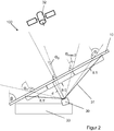
- FIG. 2 shows a disc assembly according to the invention 100.
- the disc assembly 100 includes, for example, a disc 10 according to the invention, as shown in FIG. 1 has been described in detail.
- the disc 10 is installed, for example, as a windshield in a vehicle.
- the installation angle ⁇ under which the disc 10 is installed to the vertical, is preferably from 50 ° to 65 ° and for example 60 °.
- the dashboard 33 is arranged below the disc 10.
- a transmitting and / or receiving unit 30 is arranged here, for example, a GPS receiver for receiving signals from satellite 32 for satellite-based navigation.
- the distance d of the transmitting and / or receiving unit 30 to the disk 10 is for example 50 cm.
- the transmitting and / or receiving region 31 of the transmitting and / or receiving unit 30 is aligned with the disk 10 and, in this example, conical, so that the transmitting and / or receiving region 31 intersects the disk 10 in a circular or elliptical manner.
- the transmitting and / or receiving region 31 is essentially congruent with the regions 8, 8, 8, 8, 8, 1 ', which have the stripped structures 4, 4, 4, 4, 4'.
- the signals emitted by satellites 32 strike the disc 10 at an incident angle ⁇ 1 ' , ⁇ 0 , ⁇ 1.
- the angle of incidence ⁇ 1' , ⁇ 0 , ⁇ 1 is determined in the plane passing through the normal direction the disc 10 and the direction of the Current paths 22 is formed.
- the angle of incidence ⁇ 1 ' , ⁇ 0 , ⁇ 1 can be determined in the plane formed by the normal direction on the disc 10 and the direction of the shortest connection between the bus bars 20.1 and 20.2.
- the central region 8.0 is arranged such that the maximum angle of incidence ⁇ max, 0, for example at the transition of the region 8.0 to the region 8.1 is 17 ° and at the transition of the region 8.0 to the region 8.1 'is 17 °.
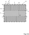
- FIG. 3A shows an enlarged view of the section Y of the disc according to the invention FIG. 1 in the middle range 8.0.
- the transparent, electrically conductive coating 3 in the central region 8.0 for example, three rows 9 with stratified structures 4.0.
- the stratified structures 4.0 are formed, for example, as a stripped rectangular frame and are stripped, for example, by laser structuring.
- the stratified structure 4.0 is completely surrounded by the transparent, electrically conductive coating 3. That is, the stratified structure 4.0 is not associated with further stratified structures or stratified interconnections or stratified areas.
- the stratified structure 4.0 is completely surrounded by the transparent, electrically conductive coating 3 at its outer edge 14 and at its inner edge 15. Due to the stratified structures 4.0, the otherwise transparent to high-frequency electromagnetic radiation, transparent electrically conductive coating 3 is permeable.
- the stratified structures 4.0 are optimized in this embodiment for the transmission of GPS-L1 signals for satellite-based navigation with a frequency of 1.575 GHz.
- the length a 0 stripped structures 4.0 is for example 55 mm.
- the width w of the stratified structures 4.0 is, for example, 1 mm.
- the aspect ratio of the length a 0 to the width w is for example 55: 1.
- the periodicity b of the stratified structures 4.0 within a row 9 is preferably constant, for example 7 mm.
- the distance h 0 of the rows 9 is for example 85 mm.
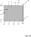
- FIG. 3B shows an enlarged view of a section of the disc according to the invention FIG. 3A .
- the stratified structures 4.0 are aligned substantially parallel to the direction of the current path 22.
- the maximum angle ⁇ between the longitudinal direction of the stratified structure 4.0 along the length a 0 and the direction of the current path 22 on average less than 30 °, preferably less than 15 ° and more preferably less than 5 °.
- the angle ⁇ between the length a of the stratified structures 4.0, 4.1, 4.1 ' is on average less than 5 °.
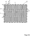
- FIG. 3C shows an enlarged view of the section Z of the disc 10 according to the invention FIG. 1 in the direction of the current path 22 extending, first area 8.1.
- the first area 8.1 here borders, for example, on the upper bus bar 20.2.
- the length a 1 stripped structures 4.1 is for example 45 mm.
- the width w stratified structures 4.1 is for example 1 mm and in this example corresponds to the width w of the stratified structures 4.0.
- the aspect ratio of the length a 1 to the width w is for example 45: 1.
- the periodicity b of the stratified structures 4.1 within a row 9 is preferably constant, for example 7 mm.
- the distance h 1 of the rows 9 is for example 5 mm.
- the stratified structures 4.1 'in the area 8.1' correspond in their arrangement and their dimensions to those of the first area 8.1 and the description of FIG. 3C , It is understood that the stratified structures 4.1 'in the area 8.1' can also have other lengths a 1 ' , widths w 1' , distances b 1 ' or distances h 1' .
- the stratified structures 4.0, 4.1, 4.1 ' are stripped, for example, by laser structuring and have only a very small line width d of, for example, 0.1 mm.
- the periodic distance b in particular affects the level of transmission transmittance and the bandwidth for high-frequency electromagnetic Radiation. It is understood that the distance b need not be constant in all areas, but are selected for the respective area such that the transmission through the disk 10 is optimized.
- the length a is matched to the high-frequency electromagnetic radiation with frequency f, for which the disc 10 should be maximum permeability.
- the length a for stratified structures 4 in a first approximation via the relationship a c / (4 * f * ( ⁇ eff ) 0.5 ) depends on the effective relative permittivity ⁇ eff of the slice 1.1, 2.1 and the intermediate layer 2, where c is the speed of light. Due to adjacently arranged rows 9 with stratified structures 4, it is possible to influence the rows 9 with one another and thus to form resonances and frequency shifts, which adapt and optimize the length a, the width b, the vertical distance d and the horizontal distance h make necessary. These can be calculated by simulations familiar to the person skilled in the art.
- the disc 10 off FIG. 2 has been optimized for the operation of satellite-based navigation (GPS).
- GPS satellite-based navigation
- the disk 10 can be optimized in a simple manner for the transmission of other frequency bands or multiple frequency bands.
- FIGS. 3A . 3B and 3C the stratified structures 4.0, 4.1, 4.1 'of a row 9 are each arranged along a straight baseline.
- Figure 3D shows one Enlarged view of a section of an alternative disc according to the invention, in which the stratified structures 4.0, 4.1, 4.1 'of a row 9 are each arranged along a curved base line 16.
- the curvature of the base line 16 preferably corresponds to the curvature of the lower or upper edge of the disc 10 or the curvature of the lower bus bar 20.1 or the upper bus bar 20.2.
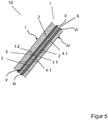
- FIG. 4 shows a cross-sectional view taken along the section AA 'from FIG. 3A using the example of a composite pane.
- the disc 10 is optimized without limiting the invention for the transmission of high-frequency electromagnetic radiation in the GPS band.
- the disk 10 comprises a composite disk 1 of two individual disks, namely a rigid first disk 1.1 and a rigid second disk 1.2, which are firmly connected to one another via a thermoplastic intermediate layer 2.
- the individual panes 1.1, 1.2 each have approximately the same size and are made, for example, of glass, in particular float glass, cast glass and ceramic glass, where they are likewise made of a non-glass material, for example plastic, in particular polystyrene (PS), polyamide (PA), polyester ( PE), polyvinyl chloride (PVC), polycarbonate (PC), polymethylmethacrylate (PMA) or polyethylene terephthalate (PET).
- PS polystyrene
- PA polyamide
- PE polyester
- PVC polyvinyl chloride
- PC polycarbonate
- PMA polymethylmethacrylate
- PET polyethylene terephthalate
- any material with sufficient transparency, sufficient chemical resistance and proper dimensional and dimensional stability can be used.
- the respective thickness of the first disk 1.1 and the second disk 1.2 may vary widely depending on the use and may be, for example, in the range of 1 to 24 mm for glass.
- the first disk 1.1 has a thickness of 2.1 mm and the second disk 1.2 has a thickness of 1.8 mm.
- the disc surfaces are denoted by the Roman numerals I-IV, wherein side I of the outside of the second disc 1.2, side II of the inside of the second disc 1.1, side III of the outside of the first disc 1.1 and side IV of the inside of the first disc 1.1 of the composite disc 1 corresponds.
- side I of the outside of the second disc 1.2 side II of the inside of the second disc 1.1
- side III of the outside of the first disc 1.1 side IV of the inside of the first disc 1.1 of the composite disc 1 corresponds.
- the side of a disc which faces the vehicle exterior.
- Inside is the side of a disc, which faces the vehicle interior.
- the side IV can also point outwards and the side I of the passenger compartment of the motor vehicle can be facing.
- the intermediate layer 2 for connecting first pane 1.1 and second pane 1.2 preferably contains an adhesive plastic, preferably based on polyvinyl butyral (PVB), ethylene vinyl acetate (EVA) or polyurethane (PU).
- PVB polyvinyl butyral
- EVA ethylene vinyl acetate
- PU polyurethane
- the composite pane 1 is transparent to visible light, for example in the wavelength range from 350 nm to 800 nm, the term "transparency” being understood to mean a light transmission of more than 50%, preferably more than 70% and especially preferably more than 75%.
- the relative permittivity number of the disks 1.1, 1.2 of the composite disk 1 is from 6 to 8 and, for example, 7 for disks made of float glass.
- the transparent, electrically conductive coating 3 is applied to the intermediate layer 2 facing side III of the inner first disc 1.1.
- the transparent, electrically conductive coating 3 serves as an electrically heatable coating.
- the transparent, electrically conductive coating 3 is for example made EP 0 847 965 B1 known and contains two silver layers, each embedded between a plurality of metal and metal oxide layers.
- the transparent, electrically conductive coating 3 has a sheet resistance of about 1 ohm / square.
- the transparent, electrically conductive coating 3, for example, also act as an infrared-reflecting layer. This means that the amount of heat radiation from incoming sunlight is reflected to a large extent. When using the composite pane 1 in a vehicle, this ensures a reduced heating of the interior in sunlight.
- the transparent, electrically conductive coating 3 can nevertheless be arranged on the side II of the outer, second pane 1.2 facing the thermoplastic intermediate layer 2, or on both inner sides of the pane II and III.
- the transparent, electrically conductive coating 3 may additionally or exclusively be arranged on one of the outer sides I and IV or both outer sides I and IV of the composite pane 1.
- the transparent, electrically conductive coating 3 is applied to the entire first pane 1.1, minus a edge-removed area 5.
- the edge deletion in area 5 prevents contact of the transparent, electrically conductive coating 3, which is advantageous in the case of corrosion-sensitive coatings.
- the second pane 1.2 for example, provided with an opaque ink layer, which is applied to the side II and forms a frame-shaped circumferential masking strip, which is not shown in detail in the figures.
- the color layer is preferably made of an electrically non-conductive, black-colored material that can be baked in the first 1.1 or the second disc 1.2.
- the masking strip prevents on the one hand the view of an adhesive strand, with which the composite pane 1 is glued into the vehicle body, on the other hand it serves as UV protection for the adhesive material used.
- FIG. 5 shows a cross-sectional view along the section AA 'from FIG. 3A an alternative embodiment of a disc 10 according to the invention with a composite disc 1.
- the first disc 1.1 and the second disc 1.2 are connected to a three-layer intermediate layer.
- the three-layer intermediate layer contains a film 6, which contains, for example, polyethylene terephthalate (PET), and which is arranged between two layers 2 of an adhesive plastic, for example polyvinyl butyral (PVB).
- PET film is formed here, for example, as a carrier of the transparent, electrically conductive coating 3.
- FIG. 6 shows a cross-sectional view along the section AA 'from FIG. 3A an alternative embodiment of a disc 10 according to the invention with a single disc 1 '.
- the transparent, electrically conductive coating 3 with the areas 9 with stripped structures 4.1, 2.4 is arranged on the inner side of the vehicle IV facing the individual pane 1 '.
- Shape and material of the single disc 1 ' correspond to the first disc 1.1 FIG. 3A
- the transparent, electrically conductive coating 3 and the areas 8.0, 8, 8, 8, 1 ' also correspond to the exemplary embodiment of FIG FIG. 3A
- the transparent, electrically conductive coating 3 is, for example, a so-called low-E layer and has a low emissivity for infrared radiation.
- the transparent, electrically conductive coating 3 contains or consists, for example, of an indium tin oxide (ITO) layer having a sheet resistance of 20 ohms / square.
- ITO indium tin oxide
- the indium-tin oxide layer is made inert to environmental influences and scratch-resistant, so that the indium-tin oxide layer, for example, on a vehicle interior facing surface of a side window of a motor vehicle can be arranged.
- Transparent, electrically conductive coatings 3 with such high surface resistances may require correspondingly high operating voltages of more than 100 V for electrical heating, as are present, for example, in electric vehicles.
- the current-carrying transparent transparent, electrically conductive coating 3 can be protected by an insulating layer containing, for example, a polymer film such as polyethylene terephthalate (PET) or polyvinyl fluoride (PVF).
- the transparent, electrically conductive coating 3 may comprise an insulating and scratch-resistant covering layer of inorganic oxides, such as silicon oxide, titanium oxide, tantalum pentoxide or combinations thereof.
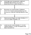
- FIG. 7A shows a flowchart of an embodiment of the inventive method for producing a disc 10 according to the invention.
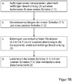
- FIG. 7B shows a flowchart of a further variant of an embodiment of the inventive method for producing a disc 10 according to the invention
- FIG. 7A be in FIG. 7B the first disk 1.1 and the second disk 1.2 first bent and then the ent harsheten structures 4.0,4.1,4.1 'introduced.
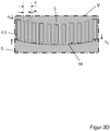
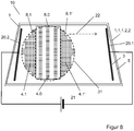
- FIG. 8 shows a further embodiment of a disc 10 according to the invention.
- the bus bars 20.1 and 20.2 are arranged in this example on the vertical sides of the disc 10.
- the heating current which forms when a voltage is applied has a current path 22, which extends horizontally in the transparent, electrically conductive coating 3 across the pane 10 on average. Since, for a sufficient and homogeneous heating power, the longer side of the stratified structures 4.0, 1.4, 1.4.1 'with the length a 0 , a 1 , a 1' must be aligned essentially parallel to the direction of the current path 22, the areas 8.0, 8.1, 8.1 'arranged in a horizontal direction next to each other.
- the stratified structures 4.0.4.1.4.1 ' are accordingly arranged horizontally with their longitudinal direction.
- the rich 9 are arranged here in the vertical direction. Otherwise corresponds to in FIG. 8 shown disc 10 of the disc 10 from FIG. 1 ,
- the disc 10 according to the invention has decisive advantages over discs according to the prior art.
- the pane 10 according to the invention can be heated electrically over the entire pane and yet has a sufficiently high transmission for electromagnetic radiation.
- the proportion of uncoated area by the Deposited Structures 4.0 in the driver's central field of vision is reduced and allows a good visual overview for the driver.
Description
Die Erfindung betrifft eine elektrisch beheizbare Scheibe, insbesondere eine Fahrzeugscheibe, mit transparenter, elektrisch leitfähiger Beschichtung und niedriger Transmissionsdämpfung für elektromagnetische Strahlung im Hochfrequenzbereich. Des Weiteren betrifft die Erfindung ein Verfahren zur Herstellung einer solchen Scheibe und deren Verwendung.The invention relates to an electrically heatable pane, in particular a vehicle window, with a transparent, electrically conductive coating and low transmission attenuation for electromagnetic radiation in the high-frequency range. Furthermore, the invention relates to a method for producing such a disc and its use.
Aktuelle Kraftfahrzeuge benötigen eine Vielzahl von technischen Einrichtungen zum Senden und Empfangen von elektromagnetischer Strahlung zum Betrieb von Grunddiensten wie Rundfunkempfang, vorzugsweise in den Bändern AM, FM oder DAB, Mobiltelefonie in den Bändern GSM 900 und DCS 1800, UMTS und LTE sowie satellitengestützer Navigation (GPS) und WLAN.Current motor vehicles require a variety of technical facilities for transmitting and receiving electromagnetic radiation for the operation of basic services such as radio reception, preferably in the bands AM, FM or DAB, mobile telephony in the bands GSM 900 and DCS 1800, UMTS and LTE and satellite-based navigation (GPS ) and WLAN.
Gleichzeitig weisen moderne Fahrzeugverglasungen zunehmend allseitige und vollflächige elektrisch leitfähige und für sichtbares Licht transparente Beschichtungen auf. Diese transparenten, elektrisch leitfähigen Beschichtungen schützen beispielsweise Innenräume vor Überhitzung durch Sonnenlicht oder Auskühlung, indem sie einfallende Wärmestrahlung reflektieren, wie aus
Den transparenten, elektrisch leitfähigen Beschichtungen ist gemeinsam, dass sie auch undurchlässig für elektromagnetische Strahlung im Hochfrequenzbereich sind. Durch eine allseitige und vollflächige Verglasung eines Fahrzeugs mit transparenten, elektrisch leitfähigen Beschichtungen ist das Senden und Empfangen von elektromagnetischer Strahlung im Innenraum nicht mehr möglich. Für den Betrieb von Sensoren wie Regensensoren, Kamerasystemen oder ortsfesten Antennen werden üblicherweise ein oder zwei örtlich begrenzte Bereiche der elektrisch leitfähigen, transparenten Beschichtung entschichtet. Diese entschichteten Bereiche bilden ein sogenanntes Kommunikationsfenster oder Datenübertragungsfenster und sind beispielsweise aus
Da die transparenten, elektrisch leitfähigen Beschichtungen die Farbgebung und Reflexionswirkung einer Scheibe beeinflussen, sind Kommunikationsfenster optisch sehr auffällig. Durch entschichtete Bereiche können sich Störungen im Sichtfeld des Fahrers ergeben, die die Fahrsicherheit beieinträchtigen und die unbedingt zu vermeiden sind. Deshalb werden Kommunikationsfenster an unauffälligen Positionen der Scheibe angeordnet, beispielsweise im Bereich des Innenspiegels einer Windschutzscheibe, und durch Schwarzdrucke und Kunststoffblenden abgedeckt.Since the transparent, electrically conductive coatings affect the coloring and reflection effect of a pane, communication windows are visually very conspicuous. Deformed areas may cause disturbances in the driver's field of vision which impair driving safety and must be avoided at all costs. Therefore, communication windows are arranged at inconspicuous positions of the disc, for example in the region of the inner mirror of a windshield, and covered by black prints and plastic screens.
Derartige Kommunikationsfenster sind zu klein um das Senden und Empfangen hochfrequenter elektromagnetischer Strahlung zu ermöglichen, wie es beispielsweise für Mobiltelefonie und satellitengestützte Navigation (GPS) notwendig ist. Dies gilt insbesondere, wenn die dafür notwendige Antenne weit von der Scheibe entfernt angeordnet ist und durch das kleine Kommunikationsfenster nur wenig Signalintensität in den Empfangsbereich der Antenne gelangen kann beziehungsweise nur wenig Signalintensität durch das Kommunikationsfenster nach außen gesendet werden kann. Dennoch erwartet der Benutzer Mobiltelefone an jeder beliebigen Position im Innenraum eines Fahrzeugs betreiben zu können.Such communication windows are too small to allow the transmission and reception of high-frequency electromagnetic radiation, as is necessary for example for mobile telephony and satellite-based navigation (GPS). This applies in particular if the antenna required for this purpose is arranged far away from the pane and because of the small communication window only little signal intensity can reach the receiving area of the antenna or only little signal intensity can be transmitted through the communication window to the outside. Nevertheless, the user expects to be able to operate mobile phones at any position in the interior of a vehicle.
Aus der
Weiterhin ist aus
Die Aufgabe der vorliegenden Erfindung besteht nunmehr darin, eine Scheibe mit transparenter, elektrisch leitfähiger Beschichtung bereitzustellen, die elektrisch beheizbar ist und die eine ausreichende Transmission von hochfrequenter elektromagnetischer Strahlung, insbesondere zum Betrieb satellitengestützer Navigation (GPS) sowie von Mobiltelefonie in den Bändern GSM 900 und DCS 1800, UMTS und LTE ermöglicht, die optisch ansprechend ist und die Durchsicht durch die Scheibe nicht wesentlich einschränkt, und die kostengünstig hergestellt werden kann. Diese und weitere Aufgaben werden nach dem Vorschlag der Erfindung durch eine Scheibe und eine Scheibenanordnung mit den Merkmalen der unabhängigen Patentansprüche gelöst. Vorteilhafte Ausgestaltungen der Erfindung sind durch die Merkmale der Unteransprüche angegeben.
Ein Verfahren zur Herstellung einer beheizbaren Scheibe mit Hochfrequenz-Transmission sowie die Verwendung einer solchen Scheibe gehen aus weiteren unabhängigen Patentansprüchen hervor.
Eine erfindungsgemäße Scheibe umfasst mindestens eine erste Scheibe mit einer Außenseite und einer Innenseite, mindestens eine transparente, elektrisch leitfähige Beschichtung, die auf der Außenseite und/oder der Innenseite der ersten Scheibe angeordnet ist und mindestens zwei zum Anschluss an eine Spannungsquelle vorgesehene Sammelleiter, die mit der transparenten, elektrisch leitfähigen Beschichtung so verbunden sind, dass zwischen den Sammelleitern ein Strompfad für einen Heizstrom geformt ist.The object of the present invention is now to provide a pane with a transparent, electrically conductive coating which is electrically heated and sufficient transmission of high-frequency electromagnetic radiation, in particular for the operation of satellite-assisted navigation (GPS) and mobile telephony in the bands GSM 900 and DCS 1800, UMTS and LTE allows, which is visually appealing and the view through the disc is not substantially restricts, and which can be produced inexpensively. These and other objects are achieved according to the proposal of the invention by a disc and a disc assembly having the features of the independent claims. Advantageous embodiments of the invention are indicated by the features of the subclaims.
A method for producing a heatable disc with high-frequency transmission and the use of such a disc are apparent from further independent claims.
A disc according to the invention comprises at least one first disc with an outer side and an inner side, at least one transparent, electrically conductive coating which is arranged on the outer side and / or the inner side of the first disc and at least two bus bars provided for connection to a voltage source the transparent, electrically conductive coating are connected so that between the bus bars, a current path is formed for a heating current.
Des Weiteren umfasst die erfindungsgemäße Scheibe mindestens drei Bereiche mit mindestens zwei Reihen von entschichteten Strukturen. Entschichtete Struktur bedeutet hier ein Abschnitt der transparenten, elektrisch leitfähigen Beschichtung in dem die Beschichtung nicht vorhanden oder entfernt ist. Reihe bedeutet hier bevorzugt die Gesamtheit von unmittelbar benachbarten entschichteten Strukturen, die im Wesentlichen orthogonal zur Richtung des Strompfads angeordnet sind. Insbesondere ist die Basislinie, also die Linie, die beispielsweise den untersten Punkt oder die unterste Linie der entschichteten Strukturen verbindet, orthogonal oder im Wesentlichen orthogonal zur Richtung des Strompfads angeordnet. Im Wesentlichen orthogonal bedeutet im Rahmen der hier vorliegenden Erfindung, dass der maximale Winkel zwischen der oben genannten Linie und der Richtung des Strompfads im Mittel zwischen 60° und 120°, bevorzugt zwischen 75° und 105° und besonders bevorzugt zwischen 85° und 95° ist.
Die entschichtete Struktur ist vollständig von der transparenten elektrisch leitfähigen Beschichtung umrandet. Das heißt mehrere entschichtete Strukturen sind nicht durch weitere Entschichtungen miteinander verbunden. Dies hat den besonderen Vorteil, dass der Heizstrom die entschichteten Strukturen umfließen kann und einen Heizbereich in der transparenten, elektrisch leitfähigen Beschichtung bildet.
Die entschichtete Struktur weist eine Länge a und eine Breite w auf, wobei die Länge a größer als die Breite w ist und die Länge a im Wesentlichen parallel zur Richtung des Strompfads angeordnet ist.
In einer alternativen Ausgestaltung der Erfindung ist die Längsrichtung der entschichteten Struktur im Wesentlichen parallel zur Richtung des kürzesten Abstandes zwischen den Sammelleitern angeordnet.
In einer weiteren alternativen Ausgestaltung der Erfindung ist die Längsrichtung der entschichteten Struktur im Wesentlichen parallel zur Richtung eines Strompfads ausgerichtet, wie er durch die gleiche Scheibe, aber ohne Bereiche mit entschichteten Strukturen, verlaufen würde.
Im Wesentlichen parallel bedeutet im Rahmen der hier vorliegenden Erfindung, dass der maximale Winkel γ zwischen der Längsrichtung der entschichteten Struktur und der Richtung des Strompfads im Mittel kleiner oder gleich 30°, bevorzugt kleiner oder gleich 15° und besonders bevorzugt kleiner oder gleich 5° ist. Idealerweise ist die Längsrichtung parallel zur Richtung des Strompfads ausgerichtet, da dies den Heizstrom am wenigsten ablenkt und sich eine sehr homogene Heizleistungsverteilung ergibt. Dies hat den Vorteil, dass dann der Einfluss auf die Gesamtleistung minimal ist. Abweichungen von der Richtung des Strompfades können aus Gründen der Ästhetik oder aus Gründen der gewünschten Umleitung des Strompfades im beschriebenen geringen Maße (≤30°) und insbesondere lokal in der unmittelbaren Umgebung der entschichteten Struktur notwendig sein. Bei der erfindungsgemäßen Scheibe weist die transparente, elektrisch leitfähige Beschichtung mindestens drei Bereiche mit entschichteten Strukturen auf, wobei die Bereiche nebeneinander, und bevorzugt unmittelbar nebeneinander, und entlang des Strompfads oder entlang der Richtung des kürzesten Abstands zwischen den Sammelleitern angeordnet sind. Das heißt, es gibt mindestens einen ersten Bereich, daran angrenzend einen mittleren Bereich und daran angrenzend einen dritten Bereich. Erfindungsgemäß weist jeder Bereich mindestens zwei Reihen von entschichteten Strukturen auf. Ein Bereich wird bevorzugt durch die Fläche definiert, die alle Reihen eines Bereichs umfasst.Furthermore, the pane according to the invention comprises at least three areas with at least two rows of stratified structures. Stripped structure here means a portion of the transparent, electrically conductive coating in which the coating is not present or removed. Row here preferably means the entirety of immediately adjacent stratified structures, which are arranged substantially orthogonal to the direction of the current path. In particular, the base line, that is to say the line which, for example, connects the lowermost point or the lowermost line of the stratified structures, is arranged orthogonally or substantially orthogonally to the direction of the current path. In the context of the present invention, essentially orthogonal means that the maximum angle between the above-mentioned line and the direction of the current path averages between 60 ° and 120 °, preferably between 75 ° and 105 ° and particularly preferably between 85 ° and 95 ° is.
The stratified structure is completely surrounded by the transparent electrically conductive coating. This means that several stratified structures are not connected to one another by further stripping. This has the particular advantage that the heating current can flow around the stripped structures and forms a heating area in the transparent, electrically conductive coating.
The stratified structure has a length a and a width w, wherein the length a is greater than the width w and the length a is arranged substantially parallel to the direction of the current path.
In an alternative embodiment of the invention, the longitudinal direction of the stratified structure is arranged substantially parallel to the direction of the shortest distance between the bus bars.
In a further alternative embodiment of the invention, the longitudinal direction of the stratified structure is oriented substantially parallel to the direction of a current path as it would pass through the same wafer but without areas with stripped structures.
In the context of the present invention, essentially parallel means that the maximum angle γ between the longitudinal direction of the stratified structure and the direction of the current path is on average less than or equal to 30 °, preferably less than or equal to 15 ° and particularly preferably less than or equal to 5 ° , Ideally, the longitudinal direction is aligned parallel to the direction of the current path, since this least distracts the heating current and results in a very homogeneous heating power distribution. This has the advantage that then the influence on the overall performance is minimal. Deviations from the direction of the current path may be necessary for reasons of aesthetics or for the sake of the desired deflection of the current path to a small degree (≤30 °) as described, and in particular locally in the immediate vicinity of the disassembled structure. In the pane according to the invention, the transparent, electrically conductive coating has at least three areas with stripped structures, wherein the areas are arranged next to each other, and preferably immediately next to one another, and along the current path or along the direction of the shortest distance between the bus bars. That is, there is at least a first region adjacent to a middle region and adjacent thereto a third region. According to the invention, each region has at least two rows of disassembled structures. A region is preferably defined by the area that encompasses all rows of a region.
In einer vorteilhaften Ausgestaltung der Erfindung sind die entschichteten Strukturen Reihen im Wesentlichen orthogonal zur Richtung des Strompfads oder zur Richtung des kürzesten Abstands zwischen den Sammelleitern angeordnet.In an advantageous embodiment of the invention, the stratified structures are arranged rows substantially orthogonal to the direction of the current path or to the direction of the shortest distance between the bus bars.
Bei der erfindungsgemäßen Scheibe beträgt das Verhältnis von Länge a zu Breite w größer 5:1, bevorzugt größer 10:1 und insbesondere von 150:1 bis 25:1. Die Länge a ist stark von der Wellenlänge abhängig, während die Breite w so klein wie möglich gewählt wird, um den Einfluss auf den Stromfluss und die homogene Heizleistungsverteilung zu minimieren und so groß wie nötig um eine gewünschte und ausreichende Transmission zu ermöglichen.In the case of the pane according to the invention, the ratio of length a to width w is greater than 5: 1, preferably greater than 10: 1 and in particular from 150: 1 to 25: 1. The length a is strongly wavelength dependent, while the width w is chosen to be as small as possible to minimize the influence on the current flow and the homogeneous heating power distribution and as large as necessary to allow a desired and sufficient transmission.
In einer vorteilhaften Ausgestaltung der erfindungsgemäßen Scheibe beträgt das Verhältnis aus Abstand b zur Breite w von 3:1 bis 20:1, bevorzugt von 5:1 bis 10:1. Für kleinere Verhältnisse ergibt sich eine sehr schlechte und inhomogene Beheizbarkeit der Scheibe. Für größere Verhältnisse ist die Transmission hochfrequenter elektromagnetischer Strahlung nur ungenügend. Der Bereich um 7:1 ist dabei besonders vorteilhaft.In an advantageous embodiment of the pane according to the invention, the ratio of distance b to width w is from 3: 1 to 20: 1, preferably from 5: 1 to 10: 1. For smaller ratios results in a very poor and inhomogeneous Heizbarkeit the disc. For larger conditions, the transmission of high-frequency electromagnetic radiation is insufficient. The range around 7: 1 is particularly advantageous.
Die erfindungsgemäße Scheibe kann als Einzelscheibe aus einer ersten Scheibe mit einer transparenten, elektrisch leitfähigen Beschichtung ausgebildet sein. Alternativ kann die erfindungsgemäße Scheibe als Verbundscheibe ausgebildet sein. Eine erfindungsgemäße Verbundscheibe umfasst bevorzugt eine erste Scheibe, eine Zwischenschicht und eine zweite Scheibe sowie mindestens eine transparente, elektrisch leitfähige Beschichtung, die zwischen der Zwischenschicht und der ersten Scheibe und/oder zwischen der Zwischenschicht und der zweiten Scheibe angeordnet ist. Die transparente, elektrisch leitfähige Beschichtung kann auch auf einer Trägerfolie angeordnet sein, die bevorzugt über weitere Zwischenschichten innerhalb der ersten und der zweiten Scheibe einlaminiert wird.The pane according to the invention can be formed as a single pane from a first pane with a transparent, electrically conductive coating. Alternatively, the disc according to the invention may be formed as a composite disc. A composite pane according to the invention preferably comprises a first pane, an intermediate layer and a second pane and at least one transparent, electrically conductive coating which is arranged between the intermediate layer and the first pane and / or between the intermediate layer and the second pane. The transparent, electrically conductive coating can also be arranged on a carrier film, which is preferably laminated via further intermediate layers within the first and the second pane.
Die erste Scheibe und/oder die zweite Scheibe kann sowohl im Falle der Einzelscheibe als auch im Falle der Verbundscheibe eine einzelne Scheibe oder eine bereits laminierte Verbundscheibe aus zwei oder mehr Scheiben sein, die durch die Lamination eine fest verbundene Einheit bilden.The first disc and / or the second disc can both in the case of single disc as well as in the case of the composite disc a single disc or a already laminated composite disc of two or more discs, which form a firmly connected unit by the lamination.
Ein weiterer Aspekt der Erfindung umfasst eine Scheibenanordnung mit mindestens einer Scheibe oder einer Verbundscheibe und mindestens einer Sende- und/oder Empfangseinheit mit mindestens einem Sende- und/oder Empfangsbereich. Die Sende- und/oder Empfangseinheit ist beispielsweise ein GPS-Empfänger oder eine Mobilfunkantenne zum Senden und Empfangen von Mobilfunksignalen.A further aspect of the invention comprises a pane arrangement with at least one pane or a composite pane and at least one transmitting and / or receiving unit with at least one transmitting and / or receiving area. The transmitting and / or receiving unit is for example a GPS receiver or a mobile radio antenna for transmitting and receiving mobile radio signals.
Die Sende- und/oder Empfangseinheit ist mit einem Abstand d auf einer Seite der Scheibe oder Verbundscheibe angeordnet und der Sende- oder Empfangsbereich auf die Scheibe oder Verbundscheibe derart ausgerichtet ist, dass ein von der gegenüberliegenden Seite der Scheibe oder Verbundscheibe eintreffendes Signal erfasst oder auf die gegenüberliegende Seite gesendet werden kann. Bei Verwendung der Scheibenanordnung in einem Fahrzeug und insbesondere als Windschutzscheibe ist die Sende- und/oder Empfangseinheit auf der dem Fahrzeuginnenraum zugewandten Seite der Scheibe angeordnet. Signal bedeutet im Rahmen der hier vorliegenden Erfindung eine hochfrequente elektromagnetische Strahlung, die von der Sende- und/oder Empfangseinheit gesendet und/oder empfangen wird.The transmitting and / or receiving unit is arranged at a distance d on one side of the disk or composite disk and the transmission or reception area is aligned with the disk or composite disk such that a signal arriving from the opposite side of the disk or composite disk is detected or detected the opposite side can be sent. When using the disc assembly in a vehicle and in particular as a windshield, the transmitting and / or receiving unit is arranged on the vehicle interior facing side of the disc. In the context of the present invention, signal means a high-frequency electromagnetic radiation which is transmitted and / or received by the transmitting and / or receiving unit.
Die Scheibe umfasst mindestens einen ersten Bereich, einen mittleren Bereich und einen dritten Bereich. Der mittlere Bereich ist vorteilhafterweise derart angeordnet, dass das Signal unter einem maximalen Einfallswinkel αmax,0 von 5° bis 30°, bevorzugt von 10° bis 20°, auf die Scheibe oder Verbundscheibe trifft oder diese verlässt. Des Weiteren ist im ersten und/oder dritten Bereich der Betrag des Einfallswinkel α größer als der maximale Einfallswinkel αmax,0. Der Einfallswinkel α wird dabei in der Ebene, die durch die Normalenrichtung auf die Scheibe oder Verbundscheibe und die Richtung des Strompfads gebildet wird, bestimmt.The disc comprises at least a first area, a middle area and a third area. The middle region is advantageously arranged in such a way that the signal strikes or leaves the pane or composite pane at a maximum angle of incidence α max, 0 from 5 ° to 30 °, preferably from 10 ° to 20 °. Furthermore, in the first and / or third region, the magnitude of the angle of incidence α is greater than the maximum angle of incidence α max, 0 . The angle of incidence α is determined in the plane which is formed by the normal direction on the disk or composite disk and the direction of the current path.
In einer vorteilhaften Ausgestaltung der Erfindung beträgt der Abstand d größer oder gleich 80 mm und bevorzugt von 80 mm bis 750 mm. Der Vorteil der erfindungsgemäßen Lösung ist in diesem Abstand d besonders groß, da somit durch die mindestens drei Bereiche eine möglichst gute Überdeckung der Fläche gegeben ist, die sich durch den Öffnungswinkel der Sende- und/oder Empfangseinheit (das heißt der Halbwertsbreite des entsprechenden Richtdiagramms) von 60° bis 150° und bevorzugt von 100° bis 140° auf der Scheibe ergibt, so dass der maximale Signaleintrag durch die Scheibe erfasst oder gesendet werden kann.In an advantageous embodiment of the invention, the distance d is greater than or equal to 80 mm and preferably from 80 mm to 750 mm. The advantage of the solution according to the invention is particularly great at this distance d, since the area which is as well as possible covered by the opening angle of the transmitting and / or receiving unit (ie the half-width of the corresponding directional diagram) is thus given by the at least three areas. from 60 ° to 150 ° and preferably from 100 ° to 140 ° on the disk, so that the maximum signal input through the disk can be detected or transmitted.
Die Fläche der Bereiche und die Fläche auf der der Sende- und/oder Empfangsbereich die Scheibe schneidet, stimmen bevorzugt zu mehr als 70%, besonders bevorzugt zu mehr als 90% überein. Insbesondere sind beide Flächen ungefähr deckungsgleich.The area of the areas and the area on which the transmission and / or reception area intersects the pane preferably correspond to more than 70%, particularly preferably to more than 90%. In particular, both surfaces are approximately congruent.
Ein weiterer Aspekt der Erfindung umfasst eine Scheibe mit mindestens einer Scheibe oder einer Verbundscheibe, wobei mindestens eine Sende- und/oder Empfangseinheit mit einem Abstand d auf einer Seite der Scheibe oder Verbundscheibe angeordnet werden kann und der Sende- oder Empfangsbereich auf die Scheibe oder Verbundscheibe derart ausgerichtet werden kann, dass ein von der gegenüberliegenden Seite der Scheibe oder Verbundscheibe eintreffendes Signal erfasst oder auf die gegenüberliegende Seite gesendet werden kann.A further aspect of the invention comprises a pane with at least one pane or a composite pane, wherein at least one transmitting and / or receiving unit can be arranged at a distance d on one side of the pane or composite pane and the transmission or reception area on the pane or composite pane can be aligned so that a signal arriving from the opposite side of the disc or composite disc can be detected or sent to the opposite side.
Eine Scheibe nach dem Stand der Technik mit einer transparenten, elektrisch leitfähigen Beschichtung dämpft eine ankommende hochfrequente elektromagnetische Strahlung um -15 dB bis -45 dB. Das heißt, die Transmission wird um einen Faktor von 6 bis 178 erniedrigt. Sende- und/oder Empfangseinheiten für das Senden und/oder Empfangen hochfrequenter elektromagnetischer Strahlung wie Mobilfunktransceiver oder GPS-Empfänger, die in einem Fahrzeug nahe einer Windschutzscheibe mit einer derartigen transparenten, elektrisch leitfähigen Beschichtung angeordnet sind, zeigen nur eine sehr eingeschränkte Funktionalität. Das Einbringen eines Kommunikationsfensters nach dem Stand der Technik bei dem die transparente, elektromagnetische Beschichtung in einem kleinen Bereich vollflächig oder rasterförmig entschichtet ist, stellen nur eine befriedigende Lösung dar, wenn die Sende- und/oder Empfangseinheit sehr nahe zur oder unmittelbar an der Windschutzscheibe angeordnet ist. Je weiter die Sende- und/oder Empfangseinheit von der Windschutzscheibe beabstandet ist, desto größer muss das Kommunikationsfenster und damit der entschichtete Bereich sein. Derartige Kommunikationsfenster sind optisch sehr auffällig und werden nur bei geeigneter Kaschierung, beispielsweise durch einen Schwarzdruck, vom Kunden akzeptiert. Des Weiteren ist der Bereich des Kommunikationsfensters großflächig nicht beheizbar.A prior art disk with a transparent, electrically conductive coating attenuates incoming high frequency electromagnetic radiation by -15 dB to -45 dB. That is, the transmission is lowered by a factor of 6 to 178. Transmitting and / or receiving units for transmitting and / or receiving high-frequency electromagnetic radiation, such as mobile radio transceivers or GPS receivers, which are arranged in a vehicle near a windscreen with such a transparent, electrically conductive coating show only a very limited functionality. The introduction of a communication window according to the prior art in which the transparent, electromagnetic coating in a small area is completely coated or raster-shaped, provide only a satisfactory solution, if the transmitting and / or receiving unit very close to or arranged directly on the windshield is. The farther the transmitting and / or receiving unit is spaced from the windshield, the larger the communication window and thus the stripped area must be. Such communication windows are visually very conspicuous and are accepted by the customer only with suitable lamination, for example by a black print. Furthermore, the area of the communication window can not be heated over a large area.
Die vorliegende Erfindung beruht nun auf der Erkenntnis, dass eine erfindungsgemäße Scheibe mit erfindungsgemäßen entschichteten Strukturen und insbesondere mit einem Aspektverhältnis von Länge zu Breite von größer 5:1 eine ausreichend hohe Durchlässigkeit für hochfrequente elektromagnetische Strahlung aufweist und die Scheibe gleichzeitig noch ausreichend und homogen beheizt werden kann. Im Gegensatz zu Scheiben nach dem Stand der Technik ist es nicht notwendig die transparente, elektrisch leitfähige Beschichtung großflächig zu entschichten. Es genügen entschichtete Strukturen mit einer nur geringen Linienbreite, die die optische Durchsicht und das ästhetische Erscheinungsbild der Scheibe nicht wesentlich beeinträchtigen. Verbessern lässt sich dies nochmals durch die Einführung von mehreren Bereichen mit einer unterschiedlichen Dichte von entschichteten Strukturen in Abhängigkeit vom Einfallswinkel des Signals auf die Scheibe. Durch eine geringe Dichte von entschichteten Strukturen im mittleren Bereich, kann die Störung der Durchsicht für den Fahrer oder die Fahrzeuginsassen geringgehalten werden. Gleichzeigt ist der Einfallwinkel α klein und es trifft genügen Signal auf die Sende- und/oder Empfangseinheit beziehungsweise nach außen. In den kritischen Bereichen mit großen Einfallswinkel α von typischerweise bis zu 70° ist die Dichte der entschichteten Strukturen erfindungsgemäß deutlich erhöht und damit die Transmission durch diese Scheibenbereiche erhöht. Gleichzeitig sind diese Bereiche für die optische Durchsicht von geringerer Bedeutung und stören den Fahrer oder die Fahrzeuginsassen nur in geringem Umfang.
Bei der erfindungsgemäßen Scheibe ist der Anteil der entschichteten Fläche an der Gesamtfläche in dem mittleren Bereich kleiner ist als der Anteil der entschichteten Fläche an der Gesamtfläche in den anderen Bereichen. Bei Scheiben mit mehr als drei Bereichen nimmt vorteilhafterweise der Anteil der entschichteten Fläche an der Gesamtfläche mit zunehmendem Abstand zum mittleren Bereich zu. Bei der erfindungsgemäßen Scheibe hat die entschichtete Struktur die Form eines vollflächig-entschichteten Rechtecks oder eines entschichteten rechteckförmigen Rahmens. Mit diesen Formen konnten besonders hohe Durchlässigkeiten für hochfrequente elektromagnetische Strahlung bei gleichzeitiger hoher Heizleistung und großer Homogenität des Heizfeldes erzielt werden. Hat die entschichtete Struktur die Form eines rechteckförmigen Rahmens, so ist die entschichtete Struktur vorteilhafterweise neben ihrem außenliegenden Rand auch noch an ihrem innenliegenden Rand vollständig von der transparenten elektrisch leitfähigen Beschichtung umrandet und besonders bevorzugt vollständig mit der transparenten elektrisch leitfähigen Beschichtung gefüllt. Mit derartigen entschichteten Strukturen konnten besonders hohe Durchlässigkeiten für hochfrequente elektromagnetische Strahlung mit nur einem geringen Strukturierungsaufwand erzielt werden. Gleichzeitig kann die Prozesszeit und die Prozesskosten niedrig gehalten werden.The present invention is based on the finding that a disc according to the invention with entschichteten structures according to the invention and in particular with an aspect ratio of length to width of greater than 5: 1 has a sufficiently high permeability to high-frequency electromagnetic radiation and the disc still heated sufficiently and homogeneously can. in the Contrary to discs according to the prior art, it is not necessary to remove the transparent, electrically conductive coating over a large area. It is sufficient to discrete structures with only a small line width, which does not significantly affect the visual clarity and the aesthetic appearance of the disc. This can be further improved by introducing several areas with a different density of stratified structures depending on the angle of incidence of the signal on the pane. Due to the low density of stratified structures in the middle area, the disturbance of the transparency for the driver or the vehicle occupants can be kept low. Gleichsein the angle of incidence α is small and it meets enough signal on the transmitting and / or receiving unit or to the outside. In the critical regions with large angles of incidence α of typically up to 70 °, the density of the layered structures is significantly increased according to the invention and thus the transmission through these slice regions is increased. At the same time, these areas are of less importance for visual inspection and disturb the driver or vehicle occupants only to a small extent.
In the case of the pane according to the invention, the proportion of the stripped area on the total area in the middle area is smaller than the proportion of the stripped area on the total area in the other areas. For slices with more than three areas advantageously increases the proportion of the stratified surface of the total area with increasing distance to the central area. In the case of the pane according to the invention, the stratified structure has the form of a full-surface stripped rectangle or a stripped rectangular frame. Particularly high permeabilities for high-frequency electromagnetic radiation with high heating power and high homogeneity of the heating field could be achieved with these molds. If the stripped structure has the shape of a rectangular frame, then the stripped structure is advantageously bordered not only by its outer edge but also by its inner edge completely by the transparent electrically conductive coating and particularly preferably completely filled with the transparent electrically conductive coating. With such stratified structures, particularly high permeabilities for high-frequency electromagnetic radiation could be achieved with only one low structuring effort can be achieved. At the same time, process time and process costs can be kept low.
In einer vorteilhaften Ausgestaltung der erfindungsgemäßen Scheibe beträgt die Periodizität zwischen den entschichteten Strukturen von 4 mm bis 20 mm, bevorzugt von 5 mm bis 10 mm. Die Periodizität beschreibt den Abstand b mit dem sich die entschichteten Strukturen in einer Reihe wiederholen. Der Abstand b nimmt dabei insbesondere Einfluss auf die Transmission und kann für die Frequenz, für die die Scheibe eine optimale Transmission aufweisen soll, optimiert werden. Der Abstand b ist bevorzugt der horizontale oder vertikale minimale Abstand zwischen zwei entschichteten Strukturen. Für Abstände b von weniger als 1 mm kann eine starke Kopplung zwischen den entschichteten Strukturen erfolgen, die zu einer unerwünschten Erhöhung der Transmissionsdämpfung führt.In an advantageous embodiment of the pane according to the invention, the periodicity between the stripped structures is from 4 mm to 20 mm, preferably from 5 mm to 10 mm. The periodicity describes the distance b with which the stratified structures are repeated in a row. The distance b in particular has an influence on the transmission and can be optimized for the frequency for which the disk should have an optimal transmission. The distance b is preferably the horizontal or vertical minimum distance between two stratified structures. For distances b of less than 1 mm, a strong coupling between the stratified structures can occur, resulting in an undesirable increase in transmission loss.
In einer weiteren vorteilhaften Ausgestaltung weisen die erfindungsgemäßen entschichteten Strukturen eine Linienbreite d von 0,025 mm bis 0,3 mm und bevorzugt von 0,03 mm bis 0,14 mm auf. Derartige Linienbreiten sind technisch einfach herzustellen, beispielsweise durch Laserstrukturierung. Des Weiteren beeinträchtigen sie wenig die optische Durchsicht durch die Scheibe.In a further advantageous embodiment, the stratified structures according to the invention have a line width d of from 0.025 mm to 0.3 mm and preferably from 0.03 mm to 0.14 mm. Such line widths are technically easy to produce, for example by laser structuring. Furthermore, they little affect the optical transparency through the disc.
In einer vorteilhaften Ausgestaltung der Erfindung beträgt der minimale Abstand h zwischen zwei benachbarten Reihen mit entschichteten Strukturen innerhalb eines Bereichs von 2 mm bis 150 mm. In einer vorteilhaften Weiterbildung der Erfindung beträgt der Abstand h0 im mittleren Bereich von 35 mm bis 120 mm und besonders bevorzugt von 70 mm bis 100 mm und der Abstand h1,h1' in den anderen Bereichen von 2 mm bis 20 mm und besonders bevorzugt von 3 mm bis 10 mm. Der minimale Abstand h ist dabei von der Frequenz abhängig, für die die Scheibe eine optimale Transmission aufweisen soll. Gleichzeitig ist er entscheidend für den Anteil der entschichteten Fläche eines Bereichs an dessen Gesamtfläche und damit für die ungestörte optische Durchsicht durch die Scheibe. Der minimale Abstand h ist bevorzugt der horizontale oder vertikale minimale Abstand zwischen zwei benachbarten Breichen. Für minimale Abstände h von weniger als 2 mm kann eine starke Kopplung zwischen den entschichteten Strukturen erfolgen, die zu einer unerwünschten Erhöhung der Transmissionsdämpfung führt.In an advantageous embodiment of the invention, the minimum distance h between two adjacent rows with stratified structures is within a range of 2 mm to 150 mm. In an advantageous development of the invention, the distance h 0 in the central region of 35 mm to 120 mm and particularly preferably from 70 mm to 100 mm and the distance h 1 , h 1 ' in the other areas of 2 mm to 20 mm and especially preferably from 3 mm to 10 mm. The minimum distance h is dependent on the frequency for which the disc should have an optimal transmission. At the same time, it is decisive for the proportion of the stratified surface of an area on its total area and thus for the undisturbed optical transparency through the pane. The minimum distance h is preferably the horizontal or vertical minimum distance between two adjacent bands. For minimum distances h of less than 2 mm, strong coupling between the stratified structures can occur, resulting in an undesirable increase in transmission loss.
Die Länge a der entschichteten Strukturen beträgt bevorzugt von 8 mm bis 150 mm. Die Länge a ist auf das Frequenzband oder die Frequenzbänder abgestimmt, für die die Scheibe eine möglichst geringe Transmissionsdämpfung aufweisen soll. Des Weiteren ist die Länge a von dem Flächenwiderstand der transparenten, elektrisch leitfähigen Beschichtung und der effektiven relativen Permittivitätszahl εeff der Scheiben und der Zwischenschicht abhängig.The length a of the stratified structures is preferably from 8 mm to 150 mm. The length a is tuned to the frequency band or the frequency bands for which the disc should have the lowest possible transmission loss. Furthermore, the length a depends on the sheet resistance of the transparent, electrically conductive coating and the effective relative permittivity ε eff of the disks and the intermediate layer.
Für einen Mobilfunkbetrieb im GSM 900-Band beträgt die Länge a bevorzugt von 35 mm bis 120 mm und besonders bevorzugt von 40 mm bis 90 mm. Im Bereich von 1,8 GHz beträgt die Länge a mit niedriger Transmissionsdämpfung bevorzugt von 20 mm bis 70 mm. Die optimale Länge a mit niedriger Transmissionsdämpfung bei ausreichender Bandbreite kann vom Fachmann im Rahmen einfacher Simulationen und Experimente ermittelt werden.For a mobile operation in the GSM 900 band, the length a is preferably from 35 mm to 120 mm and particularly preferably from 40 mm to 90 mm. In the range of 1.8 GHz, the length a with low transmission loss is preferably from 20 mm to 70 mm. The optimal length a with low transmission loss with sufficient bandwidth can be determined by the skilled person in the context of simple simulations and experiments.
Für einen Empfang von GPS-Signalen zur sattelitengestützten Navigation beträgt die Länge a bevorzugt von 35 mm bis 120 mm und besonders bevorzugt von 40 mm bis 60 mm. Im Bereich von 1,5 GHz beträgt die Länge a mit niedriger Transmissionsdämpfung bevorzugt von 40 mm bis 60 mm. Die optimale Länge a mit niedriger Transmissionsdämpfung bei ausreichender Bandbreite kann vom Fachmann im Rahmen einfacher Simulationen und Experimente ermittelt werden.For a reception of GPS signals for satellite-aided navigation, the length a is preferably from 35 mm to 120 mm and particularly preferably from 40 mm to 60 mm. In the range of 1.5 GHz, the length a with low transmission loss is preferably from 40 mm to 60 mm. The optimal length a with low transmission loss with sufficient bandwidth can be determined by the skilled person in the context of simple simulations and experiments.
In einer weiteren bevorzugten Ausführungsform beträgt die Länge a der entschichteten Strukturen, unter Vernachlässigung des Flächenwiderstands, von ![]()
![]()
![]()
![]()
![]()
![]()
In einer weiteren vorteilhaften Ausgestaltung der erfindungsgemäßen Scheibe ist die Länge a0 der entschichteten Struktur in dem mittleren Bereich größer ist als die Länge a1 im ersten Bereich und/oder die Länge a1' im dritten Bereich. Hochfrequente elektromagnetische Strahlung tritt in den unterschiedlichen Bereichen unter einen unterschiedlichen Einfallswinkel durch die Scheibe. Im mittleren Bereich ist der Einfallswinkel gering und in den von dem mittleren Bereich entfernten Bereichen größer. Auch die Länge a0 kann für größere Einfallswinkel im ersten bzw. dritten Bereich an die andere Anregungssituation mit verkürzten Abständen h angepasst sein und in der beschriebenen Ausgestaltung kleiner oder größer gewählt werden.In a further advantageous embodiment of the pane according to the invention, the length a 0 of the stratified structure in the middle region is greater than the length a 1 in the first region and / or the length a 1 ' in the third region. High-frequency electromagnetic radiation occurs in the different areas at a different angle of incidence through the disk. In the middle region, the angle of incidence is small and larger in the regions remote from the middle region. Also, the length a 0 can for larger angles of incidence in the first and third Be adapted range to the other excitation situation with shortened distances h and be chosen smaller or larger in the described embodiment.
Es versteht sich, dass die Sammelleiter sowohl horizontal als auch vertikal als auch in einer anderen Richtung auf der Scheibe angeordnet sein können. Folglich sind auch die Längsseiten der entschichteten Strukturen vertikal, horizontal oder in anderen Richtungen anzuordnen.It is understood that the bus bars can be arranged both horizontally and vertically as well as in a different direction on the disc. Consequently, the longitudinal sides of the stratified structures are to be arranged vertically, horizontally or in other directions.
Die Scheibe enthält bevorzugt Glas, besonders bevorzugt Flachglas, Floatglas, Quarzglas, Borosilikatglas, Kalk-Natron-Glas, oder klare Kunststoffe, vorzugsweise starre klare Kunststoffe, insbesondere Polyethylen, Polypropylen, Polycarbonat, Polymethylmethacrylat, Polystyrol, Polyamid, Polyester, Polyvinylchlorid und/oder Gemische davon. Geeignete Gläser sind beispielsweise aus
Die Dicke der Scheibe kann breit variieren und so hervorragend den Erfordernissen des Einzelfalls angepasst werden. Vorzugsweise werden Scheiben mit den Standardstärken von 1,0 mm bis 25 mm und bevorzugt von 1,4 mm bis 2,1 mm verwendet. Die Größe der Scheibe kann breit variieren und richtet sich nach der Größe der erfindungsgemäßen Verwendung.The thickness of the disc can vary widely and so perfectly adapted to the requirements of the case. It is preferred to use discs with the standard thicknesses of 1.0 mm to 25 mm and preferably of 1.4 mm to 2.1 mm. The size of the disc can vary widely and depends on the size of the use according to the invention.
In einer vorteilhaften Ausgestaltung der Erfindung hat die Scheibe dielektrische Eigenschaften und eine relative Permittivitätszahl von 2 bis 8. Eine Scheibe aus Polymeren hat bevorzugt eine relative Permittivitätszahl von 2 bis 5. Eine Scheibe aus Glas hat bevorzugt eine relative Permittivitätszahl von 6 bis 8 und insbesondere von etwa 7.In an advantageous embodiment of the invention, the wafer has dielectric properties and a relative permittivity of 2 to 8. A slice of polymers preferably has a relative permittivity of 2 to 5. A slice of glass preferably has a relative permittivity of 6 to 8, and more preferably about 7.
Die Scheibe kann eine beliebige dreidimensionale Form aufweisen. Vorzugsweise hat die dreidimensionale Form keine Schattenzonen, so dass sie beispielsweise durch Kathodenzerstäubung beschichtet werden kann. Bevorzugt ist die Scheibe planar oder leicht oder stark in eine Richtung oder in mehrere Richtungen des Raumes gebogen. Die Scheibe kann farblos oder gefärbt sein.The disc may have any three-dimensional shape. Preferably, the three-dimensional shape has no shadow zones, so that it can be coated, for example, by sputtering. Preferably, the disc is planar or slightly or strongly bent in one direction or in several directions of the space. The disc can be colorless or colored.
In einer bevorzugten Ausführungsform der erfindungsgemäßen Scheibe als Verbundscheibe enthält mindestens eine der Scheiben Glas und mindestens eine der Scheiben enthält Kunststoff. Insbesondere bei einer erfindungsgemäßen Verwendung als Fahrzeugscheibe enthält die außenliegende Scheibe Glas und die innenliegende Scheibe Kunststoff.In a preferred embodiment of the pane according to the invention as a composite pane, at least one of the panes contains glass and at least one of the panes contains plastic. In particular, in a use according to the invention as a vehicle window, the outer pane contains glass and the inner pane plastic.
Die Scheiben der Verbundscheibe werden durch mindestens eine Zwischenschicht miteinander verbunden. Die Zwischenschicht enthält vorzugsweise einen thermoplastischen Kunststoff, wie Polyvinylbutyral (PVB), Ethylenvinylacetat (EVA), Polyurethan (PU), Polyethylenterephthalat (PET) oder mehrere Schichten davon, bevorzugt mit Dicken von 0,3 mm bis 0,9 mm.The discs of the composite disc are connected to each other by at least one intermediate layer. The intermediate layer preferably contains a thermoplastic such as polyvinyl butyral (PVB), ethylene vinyl acetate (EVA), polyurethane (PU), polyethylene terephthalate (PET) or multiple layers thereof, preferably with thicknesses of 0.3 mm to 0.9 mm.
Die erfindungsgemäße transparente, elektrisch leitfähige Beschichtung ist für elektromagnetische Strahlung, vorzugsweise elektromagnetische Strahlung einer Wellenlänge von 300 bis 1.300 nm, insbesondere für sichtbares Licht, durchlässig. "Durchlässig" bedeutet, dass die Gesamttransmission der Verbundscheibe den gesetzlichen Bestimmungen für Windschutzscheiben und vorderen Seitenscheiben entspricht und insbesondere für sichtbares Licht bevorzugt >70% und insbesondere >75% durchlässig ist. Für hintere Seitenscheiben und Heckscheiben kann "Durchlässig" auch 10% bis 70% Lichttransmission bedeuten.The transparent, electrically conductive coating according to the invention is permeable to electromagnetic radiation, preferably electromagnetic radiation of a wavelength of 300 to 1,300 nm, in particular for visible light. "Permeable" means that the total transmission of the composite disc meets the legal requirements for windscreens and front side windows and in particular for visible light preferably> 70% and in particular> 75% is permeable. For rear side windows and rear windows, "transmissive" can also mean 10% to 70% light transmission.
Die transparente, elektrisch leitfähige Beschichtung ist bevorzugt eine funktionelle Beschichtung, besonders bevorzugt eine funktionelle Beschichtung mit SonnenschutzWirkung. Eine Beschichtung mit Sonnenschutzwirkung weist reflektierende Eigenschaften im Infrarot-Bereich und damit im Bereich der Sonneneinstrahlung auf. Dadurch wird ein Aufheizen des Innenraums eines Fahrzeugs oder Gebäudes infolge von Sonnenstrahlung vorteilhaft vermindert. Solche Beschichtungen sind dem Fachmann bekannt und enthalten typischerweise zumindest ein Metall, insbesondere Silber oder eine silberhaltige Legierung. Die transparente, elektrisch leitfähige Beschichtung kann eine Abfolge mehrerer Einzelschichten umfassen, insbesondere zumindest eine metallische Schicht und dielektrische Schichten, die beispielsweise zumindest ein Metalloxid enthalten. Das Metalloxid enthält bevorzugt Zinkoxid, Zinnoxid, Indiumoxid, Titanoxid, Siliziumoxid, Aluminiumoxid oder dergleichen sowie Kombinationen von einem oder mehreren daraus. Das dielektrische Material kann auch Siliziumnitrid, Siliziumcarbid oder Aluminiumnitrid enthalten.The transparent, electrically conductive coating is preferably a functional coating, particularly preferably a functional coating having a sunscreen effect. A coating with a sunscreen effect has reflective properties in the infrared range and thus in the range of solar radiation. As a result, a heating of the interior of a vehicle or building due to solar radiation is advantageously reduced. Such coatings are known to the person skilled in the art and typically contain at least one metal, in particular silver or a silver-containing alloy. The transparent, electrically conductive coating may comprise a sequence of a plurality of individual layers, in particular at least one metallic layer and dielectric layers containing, for example, at least one metal oxide. The metal oxide preferably contains zinc oxide, tin oxide, indium oxide, titanium oxide, silicon oxide, aluminum oxide or the like and combinations of one or more thereof. The dielectric material may also include silicon nitride, silicon carbide or aluminum nitride.
Dieser Schichtaufbau wird im Allgemeinen durch eine Folge von Abscheidevorgängen erhalten, die durch ein Vakuumverfahren wie die magnetfeldgestützte Kathodenzerstäubung durchgeführt wird. Auf beiden Seiten der Silberschicht können auch sehr feine Metallschichten vorgesehen werden, die insbesondere Titan oder Niob enthalten. Die untere Metallschicht dient als Haft- und Kristallisationsschicht. Die obere Metallschicht dient als Schutz- und Getterschicht, um eine Veränderung des Silbers während der weiteren Prozessschritte zu verhindern.This layer construction is generally obtained by a series of deposition processes performed by a vacuum process such as magnetic field assisted sputtering. On both sides of the silver layer can also be very fine metal layers are provided which contain in particular titanium or niobium. The lower metal layer serves as an adhesion and crystallization layer. The upper metal layer serves as a protective and getter layer to prevent a change of the silver during the further process steps.
Besonders geeignete transparente, elektrisch leitfähige Beschichtungen enthalten mindestens ein Metall, bevorzugt Silber, Nickel, Chrom, Niob, Zinn, Titan, Kupfer, Palladium, Zink, Gold, Cadmium, Aluminium, Silizium, Wolfram oder Legierungen daraus, und/oder mindestens eine Metalloxidschicht, bevorzugt Zinn-dotiertes Indiumoxid (ITO), Aluminium-dotiertes Zinkoxid (AZO), Fluor-dotiertes Zinnoxid (FTO, SnO2:F), Antimon-dotiertes Zinnoxid (ATO, SnO2:Sb), und/oder Kohlenstoffnanoröhrchen und/oder optisch transparente, elektrisch leitfähige Polymere, bevorzugt Poly(3,4-ethylenedioxythiophene), Polystyrensulfonat, Poly(4,4-dioctylcylopentadithiophen), 2,3-Dichloro-5,6-dicyano-1,4-benzoquinon, Gemische und/oder Copolymere davonParticularly suitable transparent, electrically conductive coatings comprise at least one metal, preferably silver, nickel, chromium, niobium, tin, titanium, copper, palladium, zinc, gold, cadmium, aluminum, silicon, tungsten or alloys thereof, and / or at least one metal oxide layer , preferably tin-doped indium oxide (ITO), aluminum-doped zinc oxide (AZO), fluorine-doped tin oxide (FTO, SnO 2 : F), antimony-doped tin oxide (ATO, SnO 2 : Sb), and / or carbon nanotubes and / or optically transparent, electrically conductive polymers, preferably poly (3,4-ethylenedioxythiophene), polystyrene sulfonate, poly (4,4-dioctylcylopentadithiophene), 2,3-dichloro-5,6-dicyano-1,4-benzoquinone, mixtures and / or copolymers thereof
Die Dicke der transparenten, elektrisch leitfähigen Beschichtung kann breit variieren und den Erfordernissen des Einzelfalls angepasst werden. Wesentlich ist dabei, dass die Dicke der transparenten, elektrisch leitfähigen Beschichtung nicht so hoch werden darf, dass sie für elektromagnetische Strahlung, vorzugsweise elektromagnetische Strahlung einer Wellenlänge von 300 bis 1.300 nm und insbesondere sichtbares Licht, undurchlässig wird. Die transparente, elektrisch leitfähige Beschichtung weist bevorzugt eine Schichtdicke von 10 nm bis 5 µm und besonders bevorzugt von 30 nm bis 1 µm auf.The thickness of the transparent, electrically conductive coating can vary widely and be adapted to the requirements of the individual case. It is essential that the thickness of the transparent, electrically conductive coating should not be so high that it is impermeable to electromagnetic radiation, preferably electromagnetic radiation of a wavelength of 300 to 1,300 nm and in particular visible light. The transparent, electrically conductive coating preferably has a layer thickness of 10 nm to 5 μm and more preferably of 30 nm to 1 μm.
Der Flächenwiderstand der transparenten, elektrisch leitfähigen Beschichtung beträgt bevorzugt von 0,35 Ohm/Quadrat bis 200 Ohm/Quadrat, bevorzugt 0,5 Ohm/Quadrat bis 200 Ohm/Quadrat, ganz besonders bevorzugt von 0,6 Ohm/Quadrat bis 30 Ohm/Quadrat, und insbesondere von 2 Ohm/Quadrat bis 20 Ohm/Quadrat. Die transparente, elektrisch leitfähige Beschichtung kann prinzipiell noch niedrigere Flächenwiderstände als 0,35 Ohm/Quadrat aufweisen, insbesondere wenn bei deren Verwendung nur eine geringe Lichttransmission benötigt wird. Die transparente, elektrisch leitfähige Beschichtung weist bevorzugt gute infrarotreflektierende Eigenschaften und/oder besonders niedrige Emissivitäten (Low-E) auf.The sheet resistance of the transparent, electrically conductive coating is preferably from 0.35 ohms / square to 200 ohms / square, preferably 0.5 ohms / square to 200 ohms / square, most preferably from 0.6 ohms / square to 30 ohms / square Square, and in particular from 2 ohms / square to 20 ohms / square. The transparent, electrically conductive coating may in principle have even lower surface resistances than 0.35 ohms / square, especially if only a small amount of light transmission is required during their use. The transparent, electrically conductive coating preferably has good infrared-reflecting properties and / or particularly low emissivities (Low-E).
Bei einer vorteilhaften Ausgestaltung der erfindungsgemäßen Verbundscheibe befindet sich mindestens eine transparente, elektrisch leitfähige Schicht auf mindestens einer der innenliegenden Seiten der Scheiben. Im Falle eines Scheibenverbundes aus zwei Scheiben kann sich eine transparente, elektrisch leitfähige Schicht auf der innenliegenden Seite der einen oder der anderen Scheiben befinden. Alternativ kann sich auch jeweils eine transparente, elektrisch leitfähige Schicht auf jeder der beiden innenliegenden Seiten befinden. Im Falle eines Scheibenverbunds aus mehr als zwei Scheiben können sich auch mehrere transparente, elektrisch leitfähige Beschichtungen auf mehreren innenliegenden Seiten der Scheiben befinden. Dabei sind die Bereiche mit entschichteten Strukturen bevorzugt deckungsgleich in den verschiedenen Beschichtungen angeordnet um eine niedrige Transmissionsdämpfung zu gewährleistenIn an advantageous embodiment of the composite pane according to the invention, at least one transparent, electrically conductive layer is located on at least one of the inner sides of the panes. In the case of a disk composite of two disks, a transparent, electrically conductive layer may be located on the inner side of one or the other disks. Alternatively, a transparent, electrically conductive layer can also be located on each of the two inner sides. In the case of a disk composite comprising more than two disks, it is also possible for a plurality of transparent, electrically conductive coatings to be located on a plurality of inner sides of the disks. The areas with stratified structures are preferably arranged congruently in the various coatings in order to ensure a low transmission attenuation
Alternativ kann eine transparente, elektrisch leitfähige Beschichtung zwischen zwei thermoplastischen Zwischenschichten eingebettet sein. Die transparente, elektrisch leitfähige Beschichtung ist dann bevorzugt auf eine Trägerfolie oder Trägerscheibe aufgebracht. Die Trägerfolie oder Trägerscheibe enthält bevorzugt ein Polymer, insbesondere Polyvinylbutyral (PVB), Ethylenvinylacetat (EVA), Polyurethan (PU), Polyethylenterephthalat (PET) oder Kombinationen daraus.Alternatively, a transparent, electrically conductive coating may be embedded between two thermoplastic intermediate layers. The transparent, electrically conductive coating is then preferably applied to a carrier film or carrier disk. The carrier film or carrier disk preferably contains a polymer, in particular polyvinyl butyral (PVB), ethylene vinyl acetate (EVA), polyurethane (PU), polyethylene terephthalate (PET) or combinations thereof.
In einer alternativen Ausgestaltung der Erfindung ist die transparente, elektrisch leitfähige Schicht oder eine Trägerfolie mit der transparenten, elektrisch leitfähigen Schicht auf einer Seite einer Einzelscheibe angeordnet.In an alternative embodiment of the invention, the transparent, electrically conductive layer or a carrier foil with the transparent, electrically conductive layer is arranged on one side of a single pane.
Die Erfindung umfasst ein Verfahren zur Herstellung einer wie oben beschriebenen erfindungsgemäßen Scheibe, wobei mindestens:
- (a) die transparente, elektrisch leitfähige Beschichtung auf der Außenseite und/oder der Innenseite einer ersten Scheibe aufgebracht wird und
- (b) mindestens drei Bereich mit mindestens zwei Reihen von entschichteten Strukturen in die transparente, elektrisch leitfähige Beschichtung eingebracht wird.
- (A) the transparent, electrically conductive coating on the outside and / or the inside of a first disc is applied and
- (B) at least three area is introduced with at least two rows of stratified structures in the transparent, electrically conductive coating.
In einer alternativen Ausführungsform des erfindungsgemäßen Verfahrens kann die transparente, elektrisch leitfähige Beschichtung auf eine Trägerfolie, beispielsweise eine PET-Folie aufgebracht werden. Die Trägerfolie kann direkt oder über mindestens eine Zwischenschicht mit der ersten Scheibe verbunden werden. Der Bereich mit den entschichteten Strukturen kann vor oder nach dem Verbinden mit der ersten Scheibe in die transparente, elektrisch leitfähige Beschichtung eingebracht werden.In an alternative embodiment of the method according to the invention, the transparent, electrically conductive coating can be applied to a carrier film, for example a PET film. The carrier film can be connected directly or via at least one intermediate layer to the first disk. The area with the Deposited structures can be introduced into the transparent, electrically conductive coating before or after bonding to the first pane.
Das Aufbringen der transparenten, elektrisch leitfähigen Beschichtung in Verfahrensschritt (a) kann durch an sich bekannte Verfahren erfolgen, bevorzugt durch magnetfeldunterstützte Kathodenzerstäubung. Das ist besonders vorteilhaft im Hinblick auf eine einfache, schnelle, kostengünstige und gleichmäßige Beschichtung der ersten Scheibe. Die transparenten, elektrisch leitfähigen Beschichtung kann aber auch beispielsweise durch Aufdampfen, chemische Gasphasenabscheidung (chemical vapour deposition, CVD), plasmagestützte Gasphasenabscheidung (PECVD) oder durch nasschemische Verfahren aufgebracht werden.The application of the transparent, electrically conductive coating in process step (a) can be effected by methods known per se, preferably by magnetic field-assisted sputtering. This is particularly advantageous in terms of a simple, fast, inexpensive and uniform coating of the first disc. However, the transparent, electrically conductive coating can also be applied, for example, by vapor deposition, chemical vapor deposition (CVD), plasma-assisted vapor deposition (PECVD) or by wet-chemical methods.
Die erste Scheibe kann nach Verfahrensschritt (a) einer Temperaturbehandlung unterzogen werden. Dabei wird die erste Scheibe mit der elektrisch leitfähigen Beschichtung auf eine Temperatur von mindestens 200°C, bevorzugt mindestens 300°C erwärmt. Die Temperaturbehandlung kann der Erhöhung der Transmission und/oder der Verringerung des Flächenwiderstands der transparenten, elektrisch leitfähigen Beschichtung dienen.The first pane may be subjected to a temperature treatment after process step (a). In this case, the first pane with the electrically conductive coating is heated to a temperature of at least 200 ° C., preferably at least 300 ° C. The temperature treatment may serve to increase the transmission and / or the reduction of the sheet resistance of the transparent, electrically conductive coating.
Die erste Scheibe kann nach Verfahrensschritt (a) gebogen werden, typischerweise bei einer Temperatur von 500°C bis 700°C. Da es technisch einfacher ist, eine plane Scheibe zu beschichten, ist dieses Vorgehen vorteilhaft, wenn die erste Scheibe gebogen werden soll. Alternativ kann die erste Scheibe aber auch vor Verfahrensschritt (a) gebogen werden, beispielsweise wenn die transparente, elektrisch leitfähige Beschichtung nicht dazu geeignet ist, einen Biegeprozess ohne Beschädigungen zu überstehen.The first disk may be bent after process step (a), typically at a temperature of 500 ° C to 700 ° C. Since it is technically easier to coat a flat disc, this procedure is advantageous if the first disc is to be bent. Alternatively, however, the first pane can also be bent before process step (a), for example if the transparent, electrically conductive coating is not suitable for withstanding a bending process without damage.
Die Entschichtung der entschichteten Strukturen in der transparenten, elektrisch leitfähigen Beschichtung erfolgt bevorzugt durch einen Laserstrahl. Verfahren zum Strukturieren dünner Metallfilme sind beispielsweise aus
Eine vorteilhafte Weiterbildung des erfindungsgemäßen Verfahrens umfasst mindestens die folgenden weiteren Schritte:
- (c) Anordnen einer thermoplastischen Zwischenschicht auf der ersten Scheibe und Anordnen einer zweiten Scheibe auf der thermoplastischen Zwischenschicht und
- (d) Verbinden der ersten Scheibe und der zweiten Scheibe über die thermoplastische Zwischenschicht.
- (c) disposing a thermoplastic intermediate layer on the first wafer and placing a second wafer on the thermoplastic intermediate layer and
- (D) connecting the first disc and the second disc via the thermoplastic intermediate layer.
In Verfahrensschritt (c) wird die erste Scheibe vorteilhafterweise so angeordnet, dass diejenige ihrer Oberflächen, welche mit der elektrisch leitfähigen Beschichtung versehen ist, der Zwischenschicht zugewandt ist. Dies hat den besonderen Vorteil, dass die transparente, elektrisch leitfähige Beschichtung durch das Einlaminieren vor Umwelteinflüssen und Berührung durch den Benutzer geschützt wird.In method step (c), the first pane is advantageously arranged so that that of its surfaces, which is provided with the electrically conductive coating, faces the intermediate layer. This has the particular advantage that the transparent, electrically conductive coating is protected by the lamination against environmental influences and contact by the user.
Die thermoplastische Zwischenschicht kann durch eine einzelne oder auch durch zwei oder mehrere thermoplastische Folien, die flächenmäßig übereinander angeordnet werden, ausgebildet werden.The thermoplastic intermediate layer can be formed by a single or by two or more thermoplastic films, which are arranged one above the other in terms of surface area.
Das Verbinden von erster und zweiter Scheibe in Verfahrensschritt (d) erfolgt bevorzugt unter Einwirkung von Hitze, Vakuum und/oder Druck. Es können an sich bekannte Verfahren zur Herstellung einer Scheibe verwendet werden.The joining of the first and second disks in process step (d) preferably takes place under the action of heat, vacuum and / or pressure. It can be used per se known methods for producing a disc.
Es können beispielsweise sogenannte Autoklavverfahren bei einem erhöhten Druck von etwa 10 bar bis 15 bar und Temperaturen von 130°C bis 145°C über etwa 2 Stunden durchgeführt werden. An sich bekannte Vakuumsack- oder Vakuumringverfahren arbeiten beispielsweise bei etwa 200 mbar und 80°C bis 110°C. Die erste Scheibe, die thermoplastische Zwischenschicht und die zweite Scheibe können auch in einem Kalander zwischen mindestens einem Walzenpaar zu einer Scheibe verpresst werden. Anlagen dieser Art sind zur Herstellung von Scheiben bekannt und verfügen normalerweise über mindestens einen Heiztunnel vor einem Presswerk. Die Temperatur während des Pressvorgangs beträgt beispielsweise von 40°C bis 150°C.For example, so-called autoclave processes can be carried out at an elevated pressure of about 10 bar to 15 bar and temperatures of 130 ° C. to 145 ° C. for about 2 hours. For example, vacuum bag or vacuum ring methods known per se operate at about 200 mbar and 80 ° C. to 110 ° C. The first disc, the thermoplastic intermediate layer and the second disc can also be pressed in a calender between at least one pair of rollers to form a disc. Plants of this type are known for the production of discs and usually have at least one heating tunnel in front of a press shop. The temperature during the pressing operation is, for example, from 40 ° C to 150 ° C.
Kombinationen von Kalander- und Autoklavverfahren haben sich in der Praxis besonders bewährt. Alternativ können Vakuumlaminatoren eingesetzt werden. Diese bestehen aus einer oder mehreren beheizbaren und evakuierbaren Kammern, in denen die erste Scheibe und die zweite Scheibe innerhalb von beispielsweise etwa 60 Minuten bei verminderten Drucken von 0,01 mbar bis 800 mbar und Temperaturen von 80°C bis 170°C laminiert werden.Combinations of calender and autoclave processes have proven particularly useful in practice. Alternatively, vacuum laminators can be used. These consist of one or more heatable and evacuable chambers in which the first disc and the second disc are laminated within, for example, about 60 minutes at reduced pressures of 0.01 mbar to 800 mbar and temperatures of 80 ° C to 170 ° C.
Zur Herstellung einer gebogenen Verbundscheibe können die erste Scheibe und die zweite Scheibe vor dem Verfahrensschritt (c) in einem an sich bekannten Heißbiegeprozess gebogen werden. Dabei können die erste und die zweite Scheibe vorteilhafterweise gemeinsam gebogen, so dass eine gleiche Krümmung der Scheiben sichergestellt ist.To produce a curved composite pane, the first pane and the second pane can be bent prior to process step (c) in a hot bending process known per se. In this case, the first and the second disc can advantageously be bent together, so that an equal curvature of the discs is ensured.
Die Erfindung erstreckt sich weiterhin auf die Verwendung einer wie oben beschriebenen Scheibe in einer Fahrzeugkarosserie oder einer Fahrzeugtür eines Fortbewegungsmittels zu Lande, zu Wasser oder in der Luft, in Gebäuden als Teil einer Außenfassade oder als Gebäudefenster und/oder als Einbauteil in Möbeln und Geräten.The invention further extends to the use of a disk as described above in a vehicle body or a vehicle door of a means of transport on land, water or in the air, in buildings as part of an external facade or as a building window and / or as a built-in part in furniture and appliances.
Die Verwendung einer erfindungsgemäßen Scheibe als Windschutzscheibe ist besonders vorteilhaft. In Städten sind die Mobilfunksendestationen üblicherweise auf Dächern oder erhöhten Positionen montiert und strahlen von oben herab. Satellitennavigationssignale strahlen ebenso von oben herab auf ein Fahrzeug ein. Die hochfrequente, elektromagnetische Strahlung kann dann in Fahrtrichtung von vorne durch die erfindungsgemäße Windschutzscheibe in den Innenraum des Fahrzeugs gelangen. Da Windschutzscheiben zur Verbesserung der Aerodynamik eine stark geneigte Einbauposition aufweisen, können Mobilfunksignale oder Satellitennavigationssignale, insbesondere von oben, durch die erfindungsgemäße Scheibe hindurch in den Fahrzeuginnenraum gelangen.The use of a pane according to the invention as a windshield is particularly advantageous. In cities, the mobile stations are usually mounted on roofs or elevated positions and radiate from above. Satellite navigation signals also radiate from above onto a vehicle. The high-frequency electromagnetic radiation can then pass in the direction of travel from the front through the windshield according to the invention into the interior of the vehicle. Since windshields have a strongly inclined installation position to improve the aerodynamics, mobile radio signals or satellite navigation signals, in particular from above, can pass through the pane according to the invention into the vehicle interior.
Die Erfindung wird nachfolgend anhand einer Zeichnung und eines Beispiels näher erläutert. Die Zeichnung ist nicht vollständig maßstabsgetreu. Die Erfindung wird durch die Zeichnung in keiner Weise eingeschränkt. Es zeigen:
Figur 1- eine schematische Darstellung einer erfindungsgemäßen Scheibe in einer Draufsicht,
Figur 2- eine Querschnittdarstellung entlang der Schnittlinie B-B'
aus Figur 1 , - Figur 3A
- eine vergrößerte Darstellung des Ausschnitts Y der erfindungsgemäßen
Scheibe aus Figur 1 , - Figur 3B
- eine vergrößerte Darstellung eines Ausschnitts der erfindungsgemäßen Scheibe aus
Figur 3A , - Figur 3C
- eine vergrößerte Darstellung des Ausschnitts Z der erfindungsgemäßen
Scheibe aus Figur 1 , - Figur 3D
- eine vergrößerte Darstellung eines Ausschnitts einer alternativen erfindungsgemäßen Scheibe,
- Figur 4
- eine Querschnittdarstellung entlang der Schnittlinie A-A' aus
Figur 3A , Figur 5- eine Querschnittdarstellung entlang der Schnittlinie A-A' aus
Figur 3A eines alternativen Ausführungsbeispiels einer erfindungsgemäßen Scheibe, Figur 6- eine Querschnittdarstellung entlang der Schnittlinie A-A' aus
Figur 3A eines weiteren alternativen Ausführungsbeispiels einer erfindungsgemäßen Scheibe, - Figur 7A
- ein Flussdiagramm eines Ausführungsbeispiels des erfindungsgemäßen Verfahrens,
- Figur 7B
- ein Flussdiagramm eines alternativen Ausführungsbeispiels des erfindungsgemäßen Verfahrens und
- Figur 8
- eine schematische Darstellung eines alternativen Ausgestaltungsbeispiels einer erfindungsgemäßen Scheibe in einer Draufsicht.
- FIG. 1
- a schematic representation of a disc according to the invention in a plan view,
- FIG. 2
- a cross-sectional view along the section line BB 'from
FIG. 1 . - FIG. 3A
- an enlarged view of the section Y of the disc according to the invention from
FIG. 1 . - FIG. 3B
- an enlarged view of a section of the disc according to the invention
FIG. 3A . - FIG. 3C
- an enlarged view of the section Z of the disc according to the invention
FIG. 1 . - Figure 3D
- an enlarged view of a section of an alternative inventive disc,
- FIG. 4
- a cross-sectional view along the section AA 'from
FIG. 3A . - FIG. 5
- a cross-sectional view along the section AA 'from
FIG. 3A an alternative embodiment of a disc according to the invention, - FIG. 6
- a cross-sectional view along the section AA 'from
FIG. 3A a further alternative embodiment of a disc according to the invention, - FIG. 7A
- a flow chart of an embodiment of the method according to the invention,
- FIG. 7B
- a flowchart of an alternative embodiment of the method according to the invention and
- FIG. 8
- a schematic representation of an alternative embodiment of an inventive disc in a plan view.
Die Scheibe 10 umfasst eine erste Scheibe 1.1 auf deren Außenseite III eine transparente elektrisch leitfähige Beschichtung 3 angeordnet ist. Entlang des unteren Scheibenrandes ist ein Sammelleiter 20.1 auf der transparenten elektrisch leitfähigen Beschichtung 3 angeordnet und mit dieser elektrisch leitend verbunden. Entlang des oberen Scheibenrandes ist ein weiterer Sammelleiter 20.2 auf der transparenten elektrisch leitfähigen Beschichtung 3 angeordnet und ebenfalls mit dieser elektrisch leitend verbunden. Die Sammelleiter 20.1 und 20.2 sind an sich bekannt und bestehen beispielsweise aus einem Metallstreifen oder einem aufgedruckten elektrisch leitfähigen Silberdruck. Die beiden Sammelleiter 20.1 und 20.2 sind jeweils beispielsweise mittig, mit einem Anschluss verbunden, mit dem die Sammelleiter 20.1 und 20.2 über Zuleitungen mit einer Spannungsquelle 21 verbunden sind. Die Spannungsquelle 21 ist beispielsweise ein Bordspannungsnetz eines Fahrzeugs oder über Spannungswandler mit einem Bordspannungsnetz eines Fahrzeugs verbunden. Das Anlegen einer Spannung an die Sammelleiter 20.1 und 20.2 führt zur Ausbildung eines Heizstromes der die transparente elektrisch leitfähige Beschichtung 3 durch ohmsche Widerstandsheizung erwärmt. Der dabei entstehende Strompfad 22 ist beispielsweise durch einen Pfeil angedeutet. Er verläuft im Wesentlichen entlang der kürzesten Verbindung zwischen den Sammelleitern 20.1 und 20.2. Bei komplizierteren Scheibengeometrien, bei mehr als zwei Sammelleitern und bei Berücksichtigung des eigenen ohmschen Widerstands der Sammelleiter 20.1 und 20.2 kann der Strompfand 22 gebogen verlaufen. Die exakten realen Strompfade lassen sich für den Fachmann einfach ermitteln, beispielsweise durch Simulationen.The
Die Signale, die von Satteliten 32 ausgesandt werden, treffen unter einem Einfallswinkel α1',α0,α1 auf die Scheibe 10. Der Einfallswinkel α1',α0,α1 wird in der Ebene bestimmt, die durch die Normalenrichtung auf die Scheibe 10 und die Richtung des Strompfads 22 gebildet wird. Alternativ kann der Einfallswinkel α1',α0,α1 in der Ebene bestimmt werden, die durch die Normalenrichtung auf die Scheibe 10 und die Richtung der kürzestens Verbindung zwischen den Sammelleitern 20.1 und 20.2 gebildet wird. Der mittlere Bereich 8.0 ist dabei derart angeordnet, dass der maximale Einfallswinkel αmax,0 beispielsweise am Übergang des Bereichs 8.0 zum Bereich 8.1 17° beträgt und am Übergang des Bereichs 8.0 zum Bereich 8.1' 17° beträgt. Dies führt dazu, dass der Betrag des Einfallswinkels α1' größer als 17° ist und der Betrag des Einfallswinkels α1 größer als 17° ist. Es versteht sich, dass der maximale Einfallswinkel αmax,0 am Übergang des Bereichs 8.0 zum Bereich 8.1 der maximale Einfallswinkel αmax,0 am Übergang des Bereichs 8.0 zum Bereich 8.1' nicht gleich sein muss.The signals emitted by
Die entschichtete Struktur 4.0 ist vollständig von der transparenten, elektrisch leitfähigen Beschichtung 3 umrandet. Das heißt, die entschichtete Struktur 4.0 ist nicht mit weitereren entschichteten Strukturen oder entschichteten Verbindungslinien oder entschichteten Flächen verbunden. Die entschichtete Struktur 4.0 ist an ihrem äußeren Rand 14 und an ihrem inneren Rand 15 vollständig von der transparenten, elektrisch leitfähigen Beschichtung 3 umgeben. Durch die entschichteten Strukturen 4.0 wird die ansonsten für hochfrequente elektromagnetische Strahlung undurchlässige, transparente elektrisch leitfähige Beschichtung 3 durchlässig.The stratified structure 4.0 is completely surrounded by the transparent, electrically
Die entschichteten Strukturen 4.0 sind in diesem Ausführungsbeispiel für die Durchlässigkeit von GPS-L1-Signalen zur satellitengestützten Navigation mit einer Frequenz von 1,575 GHz optimiert. Die Länge a0 entschichteten Strukturen 4.0 beträgt beispielsweise 55 mm. Die Breite w der entschichteten Strukturen 4.0 beträgt beispielsweise 1 mm. Das Aspektverhältnis der Länge a0 zur Breite w beträgt beispielsweise 55:1.The stratified structures 4.0 are optimized in this embodiment for the transmission of GPS-L1 signals for satellite-based navigation with a frequency of 1.575 GHz. The length a 0 stripped structures 4.0 is for example 55 mm. The width w of the stratified structures 4.0 is, for example, 1 mm. The aspect ratio of the length a 0 to the width w is for example 55: 1.
Die Periodizität b der entschichteten Strukturen 4.0 innerhalb einer Reihe 9 ist bevorzugt konstant und beträgt beispielsweise 7 mm. Der Abstand h0 der Reihen 9 beträgt beispielsweise 85 mm.The periodicity b of the stratified structures 4.0 within a row 9 is preferably constant, for example 7 mm. The distance h 0 of the rows 9 is for example 85 mm.
Die entschichteten Strukturen 4.1' im Bereich 8.1' entsprechen in ihrer Anordnung und ihren Abmessungen denjenigen aus dem ersten Bereich 8.1 und der Beschreibung zur
Die entschichteten Strukturen 4.0, 4.1, 4.1' werden beispielsweise durch Laserstrukturierung entschichtet und haben nur eine sehr geringe Linienbreite d von beispielsweise 0,1 mm.The stratified structures 4.0, 4.1, 4.1 'are stripped, for example, by laser structuring and have only a very small line width d of, for example, 0.1 mm.
Der periodische Abstand b nimmt insbesondere Einfluss auf die Höhe der Transmissionsdurchlässigkeit und auf die Bandbreite für hochfrequente elektromagnetische Strahlung. Es versteht sich, dass der Abstand b nicht in allen Bereichen konstant sein muss, sondern für den jeweiligen Bereich derart gewählt werden, dass die Transmission durch die Scheibe 10 optimiert wird.The periodic distance b in particular affects the level of transmission transmittance and the bandwidth for high-frequency electromagnetic Radiation. It is understood that the distance b need not be constant in all areas, but are selected for the respective area such that the transmission through the
Eine Optimierung erfolgt über die Parameter Länge a, Breite w, die Dichte der entschichteten Strukturen, die sich aus dem periodischen Abstand b und dem Abstand h ergibt, sowie dem Flächenwiderstand. In der folgenden Tabelle sind zur besseren Übersicht die jeweiligen Parameter und deren hauptsächliche Einflussgröße dargestellt:
Die Länge a ist auf die hochfrequente elektromagnetische Strahlung mit Frequenz f abgestimmt, für die die Scheibe 10 maximal durchlässig sein soll. Die Länge a ist für entschichtete Strukturen 4 in erster Näherung über die Beziehung a = c/(4*f*(εeff)0,5) von der effektiven relativen Permittivitätszahl εeff der Scheibe 1.1,1.2 und der Zwischenschicht 2 abhängig, wobei c die Lichtgeschwindigkeit ist. Auf Grund von benachbart angeordneten Reihen 9 mit entschichteten Strukturen 4 kann es zur Beeinflussung der Reihen 9 untereinander und damit zur Ausbildung von Resonanzen und Frequenzverschiebungen, die eine Anpassung und Optimierung der Länge a, der Breite b, des vertikalen Abstands d und des horizontalen Abstand h notwendig machen. Diese können durch dem Fachmann geläufige Simulationen berechnet werden.The length a is matched to the high-frequency electromagnetic radiation with frequency f, for which the
Die Scheibe 10 aus
In den
Die Scheibenflächen sind mit den römischen Ziffern I-IV bezeichnet, wobei Seite I der Außenseite der zweiten Scheibe 1.2, Seite II der Innenseite der zweiten Scheibe 1.1, Seite III der Außenseite der ersten Scheibe 1.1 und Seite IV der Innenseite der ersten Scheibe 1.1 der Verbundscheibe 1 entspricht. Außenseite ist im Sinne der vorliegenden Erfindung die Seite einer Scheibe, die dem Fahrzeugaußenraum zugewandt ist. Innenseite ist die Seite einer Scheibe, die dem Fahrzeuginnenraum zugewandt ist. In der Verwendung als Windschutzscheibe ist die Seite I der äußeren Umgebung und die Seite IV der Fahrgastzelle des Kraftfahrzeugs zugewandt. Es versteht sich, dass die Seite IV auch nach außen weisen kann und die Seite I der Fahrgastzelle des Kraftfahrzeugs zugewandt sein kann.The disc surfaces are denoted by the Roman numerals I-IV, wherein side I of the outside of the second disc 1.2, side II of the inside of the second disc 1.1, side III of the outside of the first disc 1.1 and side IV of the inside of the first disc 1.1 of the
Die Zwischenschicht 2 zur Verbindung von erster Scheibe 1.1 und zweiter Scheibe 1.2 enthält vorzugsweise einen klebenden Kunststoff bevorzugt auf Basis von Polyvinylbutyral (PVB), Ethylen-Vinyl-Acetat (EVA) oder Polyurethan (PU).The
Die Verbundscheibe 1 ist für sichtbares Licht beispielsweise im Wellenlängenbereich von 350 nm bis 800 nm transparent, wobei unter dem Begriff "Transparenz" eine Lichtdurchlässigkeit von mehr als 50%, vorzugsweise mehr als 70% und insbesondere bevorzugt mehr als 75% zu verstehen ist.The
Die relative Permittivitätszahl der Scheiben 1.1,1.2 der Verbundscheibe 1 beträgt für Scheiben aus Floatglas von 6 bis 8 und beispielsweise 7.The relative permittivity number of the disks 1.1, 1.2 of the
Im dargestellten Beispiel ist die transparente, elektrisch leitfähige Beschichtung 3 auf die der Zwischenschicht 2 zugewandten Seite III der innenliegenden ersten Scheibe 1.1 aufgebracht. Die transparente, elektrisch leitfähige Beschichtung 3 dient als elektrisch beheizbare Beschichtung. Die transparente, elektrisch leitfähige Beschichtung 3 ist beispielsweise aus
Die transparente, elektrisch leitfähige Beschichtung 3 kann gleichwohl auf die der thermoplastischen Zwischenschicht 2 zugewandten Seite II der außenliegenden, zweiten Scheibe 1.2, oder auf beiden Scheibeninnenseiten II und III angeordnet sein. Die transparente, elektrisch leitfähige Beschichtung 3 kann zusätzlich oder ausschließlich auf einer der Außenseiten I und IV oder beiden Außenseiten I und IV der Verbundscheibe 1 angeordnet sein.The transparent, electrically
Die transparente, elektrisch leitfähige Beschichtung 3 ist auf der gesamten ersten Scheibe 1.1 aufgebracht, abzüglich eines randentschichteten Bereichs 5. Die Randentschichtung im Bereich 5 verhindert einen Kontakt der transparenten, elektrisch leitfähigen Beschichtung 3, was bei korrosionsempfindlichen Beschichtungen vorteilhaft ist. Weiterhin ist die zweite Scheibe 1.2 beispielsweise mit einer opaken Farbschicht versehen, die auf der Seite II aufgebracht ist und einen rahmenförmig umlaufenden Maskierungsstreifen bildet, welcher in den Figuren nicht näher dargestellt ist. Die Farbschicht besteht vorzugsweise aus einem elektrisch nichtleitenden, schwarz eingefärbten Material, das in die erste 1.1 oder die zweite Scheibe 1.2 eingebrannt werden kann. Der Maskierungsstreifen verhindert einerseits die Sicht auf einen Klebestrang, mit dem die Verbundscheibe 1 in die Fahrzeugkarosserie eingeklebt ist, andererseits dient er als UV-Schutz für das verwendete Klebematerial.The transparent, electrically
Die erfindungsgemäße Scheibe 10 weist entscheidende Vorteile zu Scheiben nach dem Stand der Technik auf. Die erfindungsgemäße Scheibe 10 ist elektrisch über die komplette Scheibe beheizbar und weist dennoch eine genügend hohe Transmission für elektromagnetische Strahlung auf. Die Anteil an entschichteter Fläche durch die entschichteten Strukturen 4.0 im zentralen Sichtfeld des Fahrers ist reduziert und ermöglicht eine gute optische Durchsicht für den Fahrer. Durch die Erhöhung des Anteils an entschichteter Fläche in den Randbereichen der Scheibe 10 mit großen Einfallswinkels α, können auch diese Bereiche 8.1,8.1' effektiv für die Transmission von hochfrequenter elektromagnetischer Strahlung genutzt werden und die Gesamttransmission der Scheibe deutlich erhöht werden.The
Dieses Ergebnis war für den Fachmann unerwartet und überraschend.This result was unexpected and surprising to the skilled person.
- 11
- Verbundscheibelaminated pane
- 1'1'
- EinzelscheibeSingle disc
- 1.11.1
- erste Scheibe,first disc,
- 1.21.2
- zweite Scheibesecond disc
- 22
- Zwischenschichtinterlayer
- 33
- transparente, elektrisch leitfähige Beschichtungtransparent, electrically conductive coating
- 4,4.0,4.1,4.1'4,4.0,4.1,4.1 '
- entschichteter Bereich, entschichtete Strukturstripped area, stripped structure
- 55
- Randentschichtungedge deletion
- 66
- Trägerfoliesupport film
- 8.0,8.1,8.1'8.0,8.1,8.1 '
- BereichArea
- 99
- Reiheline
- 1010
- Scheibedisc
- 1414
- außenliegender Randoutboard edge
- 1515
- innenliegender Randinside edge
- 1616
- Basislinie einer Reihe 9Baseline of a series 9
- 20.1,20.220.1,20.2
- Sammelleiterbusbars
- 2121
- Spannungsquellevoltage source
- 2222
- Strom pfadElectricity path
- 3030
- Sende- und/oder EmpfangseinheitTransmitting and / or receiving unit
- 3131
- Sende- und/oder EmpfangsbereichTransmitting and / or receiving area
- 3232
- Satellitsatellite
- 3333
- Armaturenbrettdashboard
- 100100
- Scheibenanordnungdisk assembly
- αα
- Einfallswinkel, AustrittswinkelAngle of incidence, exit angle
- ββ
-
Einbauwinkel der Scheibe 10Installation angle of the
disc 10 - γγ
-
Winkel zwischen entschichteter Struktur 4 und Strompfad 22Angle between stratified structure 4 and
current path 22 - A-A'A-A '
- Schnittlinieintersection
- B-B'B-B '
- Schnittlinieintersection
- a, a0, a1, a1' a, a 0 , a 1 , a 1 '
- Länge einer entschichteten Struktur 4,4.0,4.1,4.1'Length of a stripped structure 4,4.0,4.1,4.1 '
- bb
- periodischer Abstand zwischen zwei entschichteten Strukturen 4 in einer Reihe 9periodic distance between two stratified structures 4 in a row 9
- dd
- Linienbreite einer entschichteten Struktur 4,4.0,4.1,4.1'Line width of a stratified structure 4,4.0,4.1,4.1 '
- εeff ε eff
- effektive relative Permittivitätszahleffective relative permittivity
- hH
- Abstand benachbarter Reihen 9 eines Bereichs 8.0,8.1,8.1'Distance between adjacent rows 9 of a range 8.0,8.1,8.1 '
- ww
- Breite einer entschichteten Struktur 4,4.0,4.1,4.1'Width of a stratified structure 4,4.0,4.1,4.1 '
- λλ
- Wellenlängewavelength
- YY
- Ausschnittneckline
- ZZ
- Ausschnittneckline
- II
- Außenseite der zweiten Scheibe 1.2Outside of the second pane 1.2
- IIII
- Innenseite der zweiten Scheibe 1.2Inner side of the second disc 1.2
- IIIIII
- Außenseite der ersten Scheibe 1.1Outside of the first pane 1.1
- IVIV
- Innenseite der ersten Scheibe 1.1Inside of the first pane 1.1
- VV
-
Seite der Zwischenschicht 2Side of the
intermediate layer 2 - VIVI
-
Seite der Zwischenschicht 2Side of the
intermediate layer 2
Claims (16)
- Pane (10), comprising:- at least one first pane (1.1) with an outer face (III) and an inner face (IV),- at least one transparent, electrically conductive coating (3), which is arranged on the outer face (III) and/or the inner face (IV) of the first pane (1.1), and- at least two busbars (20.1, 20.2), which are provided for connecting to a voltage source (21) and which are connected to the transparent, electrically conductive coating (3) such that a current path (22) for a heating current is formed between the busbars (20.1, 20.2),wherein- the transparent, electrically conductive coating (3) has at least three regions (8.1,8.0,8.1') with de-coated structures (4),- the regions (8.1,8.0,8.1') are arranged adjacent one another and along the current path (22),- each region (8.1,8.0,8.1') has at least two rows (9) of de-coated structures (4), and- the de-coated structure (4) has the form of a full-surface de-coated rectangle or of a de-coated rectangular frame with a length a and a width w, wherein the length a is greater than the width w and a maximum angle γ between the longitudinal direction of the de-coated structure (4) and the direction of the current path (22) is, on average, less than or equal to 30°,characterized in that- the ratio of length a to width w is greater than 5:1,- the proportion of the de-coated area to the total area in the central region (8.0) of the pane (10) is less than the proportion of the de-coated area to the total area in the upper region (8.1) of the pane (10) and/or the lower region (8.1') of the pane (10).
- Pane (10) according to claim 1, wherein the ratio of length a to width w is greater than 10:1, and in particular is from 150:1 to 25:1.
- Pane (10) according to one of claims 1 or 2, wherein the length a of the de-coated structure (4) is from 8 mm to 150 mm.
- Pane (10) according to one of claims 1 through 3, wherein the length a of the de-coated structure (4) is from


- Pane (10) according to one of claims 1 through 4, wherein the length a0 of the de-coated structure (4) in the central region (8.0) of the pane (10) is greater than the length a1 in the upper region (8.1) of the pane (10) and/or the length a1' in the lower region (8.1') of the pane (10).
- Pane (10) according to one of claims 1 through 5, wherein a line width d of the de-coated structure (4) is from 25 µm to 300 µm and preferably 30 µm to 140 µm.
- Pane (10) according to one of claims 1 through 6, wherein a periodic distance b between two de-coated structures (4) immediately adjacent in a row is from 4 mm to 20 mm and preferably from 5 mm to 10 mm and particularly preferably is constant and/or the ratio of distance b to the width w is from 3:1 to 20:1, preferably from 5:1 to 10:1.
- Pane (10) according to one of claims 1 through 7, wherein a minimum distance h in the direction of the current path (22) between adjacent rows (9) is from 2 mm to 150 mm.
- Pane (10) according to one of claims 1 through 8, wherein the region (8.0,8.1,8.1') has at least two rows (9), preferably 3 to 7 rows (9) and/or each row (9) has at least two, preferably 5 to 200 and particularly preferably 20 to 110 de-coated structures (4.0,4.1,4.1').
- Pane (10) according to one of claims 1 through 9, wherein the first pane (1.1) and/or the second pane (1.2) contains glass, preferably flat glass, float glass, quartz glass, borosilicate glass, soda lime glass, or polymers, preferably polyethylene, polypropylene, polycarbonate, polymethyl methacrylate, and/or mixtures thereof and/or has an effective relative permittivity εeff from 2 to 8 and preferably from 6 to 8.
- Pane (10) according to one of claims 1 through 10, wherein the transparent, electrically conductive coating (3) contains at least one metal, preferably silver, nickel, chromium, niobium, tin, titanium, copper, palladium, zinc, gold, cadmium, aluminum, silicon, tungsten, or alloys thereof, and/or at least one metal oxide layer, preferably tin-doped indium oxide (ITO), aluminum-doped zinc oxide (AZO), fluorine-doped tin oxide (FTO, SnO2:F), antimony-doped tin oxide(ATO, SnO2:Sb), and/or carbon nanotubes and/or optically transparent, electrically conductive polymers, preferably poly(3,4-ethylenedioxythiophenes), polystyrene sulfonate, poly(4,4-dioctyl cylopentadithiophene), 2,3-dichloro-5,6-dicyano-1,4-benzoquinone, mixtures and/or copolymers thereof and/or the transparent, electrically conductive coating (3) has a sheet resistance from 0.35 ohm/square to 200 ohm/square, preferably 0.35 ohm/square to 30 ohm/square.
- Laminated pane (1) comprising at least:- a pane (10) according to one of claims 1 through 11 and- a second pane (1.2) that is areally bonded to the pane (10) via at least one intermediate layer (2).
- Pane arrangement (100) comprising at least:- a pane (10) according to one of claims 1 through 11 or a laminated pane (1) according to claim 12 and- a transmitting and/or receiving unit (30) with a transmitting and/or receiving region (31),
wherein- the transmitting and/or receiving unit (30) is arranged on one face of the pane (10) or laminated pane (1) and the transmitting or receiving region (31) is aligned on the pane (10) or laminated pane (1) such that an incoming signal from the opposite side can be acquired or sent to the opposite side,- the central region (8.0) of the pane (10) is arranged such that the signal strikes or exits the pane (10) or laminated pane (1) at a maximum angle of incidence αmax,0 from 5° to 30°, preferably from 10° to 20°, and- in the upper or lower region (8.1, 8.1') of the pane (10) the amount of the angle of incidence α is greater than the maximum angle of incidence αmax,0. - Pane arrangement (100) according to claim 13, wherein the distance d between the transmitting and/or receiving unit (30) and the pane (10) or laminated pane (1) is greater than 80 mm and preferably from 80 mm to 750 mm.
- Method for producing a pane (10) according to one of claims 1 through 11, wherein at least:a. a transparent, electrically conductive coating (3) is applied on the outer face (III) and/or the inner face (IV) of a first pane (1.1), andb. at least three regions (8.0,8.1,8.1') with at least two rows (9) of de-coated structures (4.0,4.1,4.1') are introduced into the transparent, electrically conductive coating (3) by laser patterning.
- Use of a pane (10) according to one of claims 1 through 11 or a laminated pane (1) according to claim 12 as a glazing with low transmission attenuation for high-frequency electromagnetic radiation, in a vehicle body or a vehicle door of a means of transportation on land, on water, or in the air, preferably as a windshield, in buildings as part of an external façade or a building window and/or as a built-in part in furniture and appliances.
Priority Applications (2)
| Application Number | Priority Date | Filing Date | Title |
|---|---|---|---|
| EP14808607.7A EP3085199B1 (en) | 2013-12-16 | 2014-12-05 | Heatable pane with high frequency transmission |
| PL14808607T PL3085199T3 (en) | 2013-12-16 | 2014-12-05 | Heatable pane with high frequency transmission |
Applications Claiming Priority (3)
| Application Number | Priority Date | Filing Date | Title |
|---|---|---|---|
| EP13197404 | 2013-12-16 | ||
| EP14808607.7A EP3085199B1 (en) | 2013-12-16 | 2014-12-05 | Heatable pane with high frequency transmission |
| PCT/EP2014/076676 WO2015091016A1 (en) | 2013-12-16 | 2014-12-05 | Heatable pane with high-frequency transmission |
Publications (2)
| Publication Number | Publication Date |
|---|---|
| EP3085199A1 EP3085199A1 (en) | 2016-10-26 |
| EP3085199B1 true EP3085199B1 (en) | 2018-08-22 |
Family
ID=49765911
Family Applications (1)
| Application Number | Title | Priority Date | Filing Date |
|---|---|---|---|
| EP14808607.7A Active EP3085199B1 (en) | 2013-12-16 | 2014-12-05 | Heatable pane with high frequency transmission |
Country Status (12)
| Country | Link |
|---|---|
| US (1) | US10536994B2 (en) |
| EP (1) | EP3085199B1 (en) |
| JP (1) | JP6456390B2 (en) |
| KR (1) | KR101964504B1 (en) |
| CN (1) | CN105981473B (en) |
| CA (1) | CA2932770C (en) |
| EA (1) | EA033458B1 (en) |
| ES (1) | ES2699005T3 (en) |
| MX (1) | MX362003B (en) |
| PL (1) | PL3085199T3 (en) |
| PT (1) | PT3085199T (en) |
| WO (1) | WO2015091016A1 (en) |
Families Citing this family (27)
| Publication number | Priority date | Publication date | Assignee | Title |
|---|---|---|---|---|
| KR20150114119A (en) * | 2014-03-31 | 2015-10-12 | (주)엘지하우시스 | Heating seat with high efficiency for car |
| JP6812730B2 (en) * | 2015-10-09 | 2021-01-13 | Agc株式会社 | Front window for vehicles and articles for vehicles using it |
| EP3435735B1 (en) * | 2016-03-24 | 2020-12-02 | NGK Insulators, Ltd. | Radiation device and processing device using same radiation device |
| US10827564B1 (en) * | 2016-08-09 | 2020-11-03 | Apple Inc. | Windows with heatable infrared-transparent areas |
| CN106304432A (en) * | 2016-09-23 | 2017-01-04 | 江阴宝曼电子科技有限公司 | The processing technology of automobile fever tablet |
| FR3057733A1 (en) * | 2016-10-13 | 2018-04-20 | Commissariat A L'energie Atomique Et Aux Energies Alternatives | USE AS A HEATING ELEMENT OF A CONDUCTIVE AND TRANSPARENT POLYMERIC FILM BASED ON POLY (THIO- OR SELENO-) PHENIC POLYMERS |
| CN108621753A (en) * | 2017-03-24 | 2018-10-09 | 凯姆控股有限公司 | Planar heating structure |
| WO2018192727A1 (en) | 2017-04-18 | 2018-10-25 | Saint-Gobain Glass France | Pane having heatable tco coating |
| US11432375B2 (en) * | 2017-10-31 | 2022-08-30 | Adasky, Ltd. | Protective window for resistive heating |
| GB201719994D0 (en) | 2017-11-30 | 2018-01-17 | Pilkington Group Ltd | Conductive pattern sheet, glazing having the same, vehicle having the glazing, method of manufacturing the sheet and method of manufacturing the glazing |
| DE102017223686A1 (en) * | 2017-12-22 | 2019-06-27 | Continental Automotive Gmbh | Disc system with a disc and a control device, vehicle equipped therewith, and use of such a disc system |
| CN108162728B (en) * | 2018-01-11 | 2019-10-18 | 福建省万达汽车玻璃工业有限公司 | A kind of coated glass with communication window |
| BR112020025866A2 (en) * | 2018-09-03 | 2021-03-23 | Saint-Gobain Glass France | vehicle window having a transponder |
| CN111612118A (en) * | 2019-02-26 | 2020-09-01 | 法国圣-戈班玻璃公司 | Coated glazing with improved readability and method for manufacturing same |
| JP2020152132A (en) * | 2019-03-18 | 2020-09-24 | 豊田合成株式会社 | Vehicle part |
| JP2022528502A (en) * | 2019-03-18 | 2022-06-14 | アスク インダストリーズ ソシエタ ペル アツィオーニ | How to manufacture the rear window of a vehicle equipped with a heater-integrated antenna |
| BR112022001601A2 (en) * | 2019-08-28 | 2022-03-22 | Saint Gobain | Panel with pattern for high frequency transmission |
| GB201916522D0 (en) * | 2019-11-13 | 2019-12-25 | Pilkington Group Ltd | Glazing having a data tranmission window, method of manufacturing the same and use of the same |
| US11677142B2 (en) | 2019-12-05 | 2023-06-13 | Agc Glass Europe | Glazing unit with a housing |
| CN114271026A (en) | 2020-04-15 | 2022-04-01 | 法国圣戈班玻璃厂 | Glass pane with an electrically heatable communication window for a sensor and a camera system |
| US20240027864A1 (en) | 2020-09-18 | 2024-01-25 | Sage Electrochromics, Inc. | Pane with a functional element having electrically switchable optical properties and pattern for high-frequency transmission |
| FR3114586B1 (en) * | 2020-09-29 | 2022-09-09 | Saint Gobain | Radio Frequency Transparent Solar Control Heated Glazing |
| CN113682009B (en) * | 2021-07-06 | 2023-04-07 | 福耀玻璃工业集团股份有限公司 | Tectorial membrane board assembly and vehicle |
| JP2023037945A (en) * | 2021-09-06 | 2023-03-16 | 日本板硝子株式会社 | glass body |
| WO2023161070A1 (en) | 2022-02-25 | 2023-08-31 | Saint-Gobain Glass France | Method for producing a curved pane which is de-coated in some regions |
| WO2023247871A1 (en) | 2022-06-23 | 2023-12-28 | Saint-Gobain Glass France | Transparent glass article for a cold compartment and multiple glazing unit incorporating the article |
| FR3137084A1 (en) | 2022-06-23 | 2023-12-29 | Saint-Gobain Glass France | Transparent glass article for cold compartment and multiple glazing incorporating said article. |
Family Cites Families (25)
| Publication number | Priority date | Publication date | Assignee | Title |
|---|---|---|---|---|
| US2878357A (en) * | 1956-07-13 | 1959-03-17 | Gen Dynamics Corp | Electric heated laminated glass panel |
| JPH02258655A (en) | 1988-12-16 | 1990-10-19 | Nippon Sheet Glass Co Ltd | Heat-radiation reflecting laminated plate |
| DE19541743A1 (en) | 1994-12-08 | 1996-06-13 | Bosch Gmbh Robert | Composite metallised glass panel with patterned metal interlayer |
| DE19503892C1 (en) | 1995-02-07 | 1996-10-24 | Sekurit Saint Gobain Deutsch | Car glass pane provided with an electrical conductive layer |
| FR2757151B1 (en) | 1996-12-12 | 1999-01-08 | Saint Gobain Vitrage | GLAZING COMPRISING A SUBSTRATE PROVIDED WITH A STACK OF THIN FILMS FOR SUN PROTECTION AND / OR THERMAL INSULATION |
| DE19817712C1 (en) | 1998-04-21 | 2000-02-03 | Sekurit Saint Gobain Deutsch | Transparent plate, in particular glass pane with a coating and a radiation window |
| JP2002020142A (en) * | 2000-06-29 | 2002-01-23 | Nippon Sheet Glass Co Ltd | Windshield for vehicle and method for manufacturing the same |
| JP3865590B2 (en) * | 2001-02-19 | 2007-01-10 | 日立建機株式会社 | Hydraulic circuit for construction machinery |
| US6492619B1 (en) * | 2001-04-11 | 2002-12-10 | Centre Luxembourgeois De Recherches Pour Le Verre Et La Ceramique S.A. (Crvc) | Dual zone bus bar arrangement for heatable vehicle window |
| JP2003069282A (en) | 2001-08-30 | 2003-03-07 | Takenaka Komuten Co Ltd | Specified electromagnetic wave transmitting plate |
| US6730389B2 (en) | 2001-10-25 | 2004-05-04 | Ppg Industries Ohio, Inc. | Coated substrate having a frequency selective surface |
| JP3994259B2 (en) * | 2001-12-06 | 2007-10-17 | 旭硝子株式会社 | Automotive window glass with conductive film and radio wave transmission / reception structure for automobile |
| DE10164063B4 (en) * | 2001-12-24 | 2007-12-06 | Saint-Gobain Sekurit Deutschland Gmbh & Co. Kg | Composite disc with an electrically controllable functional element |
| US7132625B2 (en) * | 2002-10-03 | 2006-11-07 | Ppg Industries Ohio, Inc. | Heatable article having a configured heating member |
| US6922175B2 (en) * | 2002-12-04 | 2005-07-26 | The Ohio State University | Radio transmission region in metallic panel |
| US6891517B2 (en) * | 2003-04-08 | 2005-05-10 | Ppg Industries Ohio, Inc. | Conductive frequency selective surface utilizing arc and line elements |
| DE20321682U1 (en) * | 2003-11-07 | 2008-11-13 | Saint-Gobain Sekurit Deutschland Gmbh & Co. Kg | Heatable composite disc |
| GB0408392D0 (en) | 2004-04-15 | 2004-05-19 | Pilkington Plc | Electrically heated window |
| US8664570B2 (en) * | 2004-10-04 | 2014-03-04 | Guardian Industries Corp. | Vehicle window having bus bar(s) of conductive black frit |
| DE102008018147A1 (en) * | 2008-04-10 | 2009-10-15 | Saint-Gobain Sekurit Deutschland Gmbh & Co. Kg | Transparent disc with a heatable coating and low-resistance conductive structures |
| ATE531083T1 (en) | 2008-06-25 | 2011-11-15 | Atec Holding Ag | DEVICE FOR STRUCTURING A SOLAR MODULE |
| DE102008051730A1 (en) | 2008-10-15 | 2010-04-22 | Saint-Gobain Sekurit Deutschland Gmbh & Co. Kg | Transparent article having a localized, structured, electrically heatable, transparent region, process for its preparation and its use |
| EP2200097A1 (en) | 2008-12-16 | 2010-06-23 | Saint-Gobain Glass France S.A. | Method of manufacturing a photovoltaic device and system for patterning an object |
| GB0914961D0 (en) * | 2009-08-27 | 2009-09-30 | Appleton Steve | Electrically heated window |
| DE102011115967A1 (en) * | 2011-10-13 | 2013-04-18 | Daimler Ag | Windshield for motor car, has intersecting lines that are interrupted at crossing points so that metallic material remains to some areas of coating portion |
-
2014
- 2014-12-05 EP EP14808607.7A patent/EP3085199B1/en active Active
- 2014-12-05 KR KR1020167018814A patent/KR101964504B1/en active IP Right Grant
- 2014-12-05 PT PT14808607T patent/PT3085199T/en unknown
- 2014-12-05 MX MX2016007854A patent/MX362003B/en active IP Right Grant
- 2014-12-05 WO PCT/EP2014/076676 patent/WO2015091016A1/en active Application Filing
- 2014-12-05 JP JP2016540478A patent/JP6456390B2/en active Active
- 2014-12-05 CN CN201480068679.6A patent/CN105981473B/en active Active
- 2014-12-05 CA CA2932770A patent/CA2932770C/en not_active Expired - Fee Related
- 2014-12-05 PL PL14808607T patent/PL3085199T3/en unknown
- 2014-12-05 US US15/100,280 patent/US10536994B2/en active Active
- 2014-12-05 ES ES14808607T patent/ES2699005T3/en active Active
- 2014-12-05 EA EA201691200A patent/EA033458B1/en not_active IP Right Cessation
Non-Patent Citations (1)
| Title |
|---|
| None * |
Also Published As
| Publication number | Publication date |
|---|---|
| JP2017510022A (en) | 2017-04-06 |
| CN105981473B (en) | 2019-05-31 |
| EA201691200A1 (en) | 2016-11-30 |
| KR101964504B1 (en) | 2019-04-01 |
| CA2932770A1 (en) | 2015-06-25 |
| WO2015091016A1 (en) | 2015-06-25 |
| US10536994B2 (en) | 2020-01-14 |
| MX362003B (en) | 2019-01-03 |
| KR20160095156A (en) | 2016-08-10 |
| PL3085199T3 (en) | 2019-02-28 |
| EA033458B1 (en) | 2019-10-31 |
| PT3085199T (en) | 2018-11-29 |
| CA2932770C (en) | 2019-08-20 |
| CN105981473A (en) | 2016-09-28 |
| ES2699005T3 (en) | 2019-02-06 |
| US20160374150A1 (en) | 2016-12-22 |
| JP6456390B2 (en) | 2019-01-23 |
| EP3085199A1 (en) | 2016-10-26 |
| MX2016007854A (en) | 2016-09-07 |
Similar Documents
| Publication | Publication Date | Title |
|---|---|---|
| EP3085199B1 (en) | Heatable pane with high frequency transmission | |
| EP3081378B1 (en) | Pane with high frequency transmission | |
| EP2380234B2 (en) | Transparent plane antenna, manufacturing method for the antenna, and use of the antenna | |
| EP3281247B1 (en) | Vehicle antenna window | |
| EP2936926B1 (en) | Glasspane with electrical heating layer | |
| EP2586610B1 (en) | Sheet with high frequency transmission | |
| EP3189706B1 (en) | Pane with electric heating area | |
| EP2936925A1 (en) | Pane having an electric heating layer | |
| EP3962733B1 (en) | Laminated glazing with a recess in the internal pane | |
| EP3178295B1 (en) | Transparent pane with an electrical heating layer, method for its production and its use | |
| EP3362284B1 (en) | Heatable laminated vehicle pane with improved heat distribution | |
| WO2022136107A1 (en) | Glazing having a light source | |
| WO2021037467A1 (en) | Windowpane with pattern for high-frequency transmission | |
| EP3847581B1 (en) | Vehicle pane with transponder | |
| EP3949007A1 (en) | Windscreen antenna | |
| DE202021101982U1 (en) | Composite pane | |
| DE202018006266U1 (en) | Vehicle window with a transponder | |
| WO2023161070A1 (en) | Method for producing a curved pane which is de-coated in some regions | |
| EP4353050A1 (en) | Pane having patterned functional coating | |
| WO2021209391A1 (en) | Glazing having sensor button | |
| WO2022129202A1 (en) | Glazing having metal-based functional layer | |
| DE202017006838U1 (en) | Electrically heated window pane with a sheet-like, net-like, electrically conductive heating structure |
Legal Events
| Date | Code | Title | Description |
|---|---|---|---|
| PUAI | Public reference made under article 153(3) epc to a published international application that has entered the european phase |
Free format text: ORIGINAL CODE: 0009012 |
|
| 17P | Request for examination filed |
Effective date: 20160517 |
|
| AK | Designated contracting states |
Kind code of ref document: A1 Designated state(s): AL AT BE BG CH CY CZ DE DK EE ES FI FR GB GR HR HU IE IS IT LI LT LU LV MC MK MT NL NO PL PT RO RS SE SI SK SM TR |
|
| AX | Request for extension of the european patent |
Extension state: BA ME |
|
| DAX | Request for extension of the european patent (deleted) | ||
| GRAP | Despatch of communication of intention to grant a patent |
Free format text: ORIGINAL CODE: EPIDOSNIGR1 |
|
| STAA | Information on the status of an ep patent application or granted ep patent |
Free format text: STATUS: GRANT OF PATENT IS INTENDED |
|
| RIC1 | Information provided on ipc code assigned before grant |
Ipc: B32B 17/10 20060101ALI20170913BHEP Ipc: H05B 3/84 20060101AFI20170913BHEP Ipc: H05B 3/86 20060101ALI20170913BHEP |
|
| INTG | Intention to grant announced |
Effective date: 20171005 |
|
| GRAJ | Information related to disapproval of communication of intention to grant by the applicant or resumption of examination proceedings by the epo deleted |
Free format text: ORIGINAL CODE: EPIDOSDIGR1 |
|
| STAA | Information on the status of an ep patent application or granted ep patent |
Free format text: STATUS: REQUEST FOR EXAMINATION WAS MADE |
|
| GRAP | Despatch of communication of intention to grant a patent |
Free format text: ORIGINAL CODE: EPIDOSNIGR1 |
|
| STAA | Information on the status of an ep patent application or granted ep patent |
Free format text: STATUS: GRANT OF PATENT IS INTENDED |
|
| INTC | Intention to grant announced (deleted) | ||
| INTG | Intention to grant announced |
Effective date: 20180305 |
|
| GRAS | Grant fee paid |
Free format text: ORIGINAL CODE: EPIDOSNIGR3 |
|
| GRAA | (expected) grant |
Free format text: ORIGINAL CODE: 0009210 |
|
| STAA | Information on the status of an ep patent application or granted ep patent |
Free format text: STATUS: THE PATENT HAS BEEN GRANTED |
|
| AK | Designated contracting states |
Kind code of ref document: B1 Designated state(s): AL AT BE BG CH CY CZ DE DK EE ES FI FR GB GR HR HU IE IS IT LI LT LU LV MC MK MT NL NO PL PT RO RS SE SI SK SM TR |
|
| REG | Reference to a national code |
Ref country code: GB Ref legal event code: FG4D Free format text: NOT ENGLISH |
|
| REG | Reference to a national code |
Ref country code: CH Ref legal event code: EP |
|
| REG | Reference to a national code |
Ref country code: AT Ref legal event code: REF Ref document number: 1034016 Country of ref document: AT Kind code of ref document: T Effective date: 20180915 |
|
| REG | Reference to a national code |
Ref country code: IE Ref legal event code: FG4D Free format text: LANGUAGE OF EP DOCUMENT: GERMAN |
|
| REG | Reference to a national code |
Ref country code: DE Ref legal event code: R096 Ref document number: 502014009273 Country of ref document: DE |
|
| REG | Reference to a national code |
Ref country code: RO Ref legal event code: EPE |
|
| REG | Reference to a national code |
Ref country code: NL Ref legal event code: FP |
|
| REG | Reference to a national code |
Ref country code: PT Ref legal event code: SC4A Ref document number: 3085199 Country of ref document: PT Date of ref document: 20181129 Kind code of ref document: T Free format text: AVAILABILITY OF NATIONAL TRANSLATION Effective date: 20181121 |
|
| REG | Reference to a national code |
Ref country code: SE Ref legal event code: TRGR |
|
| REG | Reference to a national code |
Ref country code: LT Ref legal event code: MG4D |
|
| PG25 | Lapsed in a contracting state [announced via postgrant information from national office to epo] |
Ref country code: FI Free format text: LAPSE BECAUSE OF FAILURE TO SUBMIT A TRANSLATION OF THE DESCRIPTION OR TO PAY THE FEE WITHIN THE PRESCRIBED TIME-LIMIT Effective date: 20180822 Ref country code: NO Free format text: LAPSE BECAUSE OF FAILURE TO SUBMIT A TRANSLATION OF THE DESCRIPTION OR TO PAY THE FEE WITHIN THE PRESCRIBED TIME-LIMIT Effective date: 20181122 Ref country code: RS Free format text: LAPSE BECAUSE OF FAILURE TO SUBMIT A TRANSLATION OF THE DESCRIPTION OR TO PAY THE FEE WITHIN THE PRESCRIBED TIME-LIMIT Effective date: 20180822 Ref country code: BG Free format text: LAPSE BECAUSE OF FAILURE TO SUBMIT A TRANSLATION OF THE DESCRIPTION OR TO PAY THE FEE WITHIN THE PRESCRIBED TIME-LIMIT Effective date: 20181122 Ref country code: IS Free format text: LAPSE BECAUSE OF FAILURE TO SUBMIT A TRANSLATION OF THE DESCRIPTION OR TO PAY THE FEE WITHIN THE PRESCRIBED TIME-LIMIT Effective date: 20181222 Ref country code: GR Free format text: LAPSE BECAUSE OF FAILURE TO SUBMIT A TRANSLATION OF THE DESCRIPTION OR TO PAY THE FEE WITHIN THE PRESCRIBED TIME-LIMIT Effective date: 20181123 Ref country code: LT Free format text: LAPSE BECAUSE OF FAILURE TO SUBMIT A TRANSLATION OF THE DESCRIPTION OR TO PAY THE FEE WITHIN THE PRESCRIBED TIME-LIMIT Effective date: 20180822 |
|
| REG | Reference to a national code |
Ref country code: ES Ref legal event code: FG2A Ref document number: 2699005 Country of ref document: ES Kind code of ref document: T3 Effective date: 20190206 |
|
| PG25 | Lapsed in a contracting state [announced via postgrant information from national office to epo] |
Ref country code: AL Free format text: LAPSE BECAUSE OF FAILURE TO SUBMIT A TRANSLATION OF THE DESCRIPTION OR TO PAY THE FEE WITHIN THE PRESCRIBED TIME-LIMIT Effective date: 20180822 Ref country code: HR Free format text: LAPSE BECAUSE OF FAILURE TO SUBMIT A TRANSLATION OF THE DESCRIPTION OR TO PAY THE FEE WITHIN THE PRESCRIBED TIME-LIMIT Effective date: 20180822 Ref country code: LV Free format text: LAPSE BECAUSE OF FAILURE TO SUBMIT A TRANSLATION OF THE DESCRIPTION OR TO PAY THE FEE WITHIN THE PRESCRIBED TIME-LIMIT Effective date: 20180822 |
|
| PG25 | Lapsed in a contracting state [announced via postgrant information from national office to epo] |
Ref country code: EE Free format text: LAPSE BECAUSE OF FAILURE TO SUBMIT A TRANSLATION OF THE DESCRIPTION OR TO PAY THE FEE WITHIN THE PRESCRIBED TIME-LIMIT Effective date: 20180822 |
|
| REG | Reference to a national code |
Ref country code: DE Ref legal event code: R097 Ref document number: 502014009273 Country of ref document: DE |
|
| PG25 | Lapsed in a contracting state [announced via postgrant information from national office to epo] |
Ref country code: SM Free format text: LAPSE BECAUSE OF FAILURE TO SUBMIT A TRANSLATION OF THE DESCRIPTION OR TO PAY THE FEE WITHIN THE PRESCRIBED TIME-LIMIT Effective date: 20180822 Ref country code: DK Free format text: LAPSE BECAUSE OF FAILURE TO SUBMIT A TRANSLATION OF THE DESCRIPTION OR TO PAY THE FEE WITHIN THE PRESCRIBED TIME-LIMIT Effective date: 20180822 |
|
| PLBE | No opposition filed within time limit |
Free format text: ORIGINAL CODE: 0009261 |
|
| STAA | Information on the status of an ep patent application or granted ep patent |
Free format text: STATUS: NO OPPOSITION FILED WITHIN TIME LIMIT |
|
| 26N | No opposition filed |
Effective date: 20190523 |
|
| REG | Reference to a national code |
Ref country code: CH Ref legal event code: PL |
|
| PG25 | Lapsed in a contracting state [announced via postgrant information from national office to epo] |
Ref country code: SI Free format text: LAPSE BECAUSE OF FAILURE TO SUBMIT A TRANSLATION OF THE DESCRIPTION OR TO PAY THE FEE WITHIN THE PRESCRIBED TIME-LIMIT Effective date: 20180822 Ref country code: MC Free format text: LAPSE BECAUSE OF FAILURE TO SUBMIT A TRANSLATION OF THE DESCRIPTION OR TO PAY THE FEE WITHIN THE PRESCRIBED TIME-LIMIT Effective date: 20180822 |
|
| REG | Reference to a national code |
Ref country code: IE Ref legal event code: MM4A |
|
| PG25 | Lapsed in a contracting state [announced via postgrant information from national office to epo] |
Ref country code: IE Free format text: LAPSE BECAUSE OF NON-PAYMENT OF DUE FEES Effective date: 20181205 |
|
| PG25 | Lapsed in a contracting state [announced via postgrant information from national office to epo] |
Ref country code: LI Free format text: LAPSE BECAUSE OF NON-PAYMENT OF DUE FEES Effective date: 20181231 Ref country code: CH Free format text: LAPSE BECAUSE OF NON-PAYMENT OF DUE FEES Effective date: 20181231 |
|
| PG25 | Lapsed in a contracting state [announced via postgrant information from national office to epo] |
Ref country code: MT Free format text: LAPSE BECAUSE OF FAILURE TO SUBMIT A TRANSLATION OF THE DESCRIPTION OR TO PAY THE FEE WITHIN THE PRESCRIBED TIME-LIMIT Effective date: 20180822 |
|
| PGFP | Annual fee paid to national office [announced via postgrant information from national office to epo] |
Ref country code: PT Payment date: 20191204 Year of fee payment: 6 Ref country code: SE Payment date: 20191210 Year of fee payment: 6 |
|
| PGFP | Annual fee paid to national office [announced via postgrant information from national office to epo] |
Ref country code: AT Payment date: 20191125 Year of fee payment: 6 |
|
| PG25 | Lapsed in a contracting state [announced via postgrant information from national office to epo] |
Ref country code: HU Free format text: LAPSE BECAUSE OF FAILURE TO SUBMIT A TRANSLATION OF THE DESCRIPTION OR TO PAY THE FEE WITHIN THE PRESCRIBED TIME-LIMIT; INVALID AB INITIO Effective date: 20141205 Ref country code: CY Free format text: LAPSE BECAUSE OF FAILURE TO SUBMIT A TRANSLATION OF THE DESCRIPTION OR TO PAY THE FEE WITHIN THE PRESCRIBED TIME-LIMIT Effective date: 20180822 Ref country code: MK Free format text: LAPSE BECAUSE OF NON-PAYMENT OF DUE FEES Effective date: 20180822 |
|
| PG25 | Lapsed in a contracting state [announced via postgrant information from national office to epo] |
Ref country code: PT Free format text: LAPSE BECAUSE OF NON-PAYMENT OF DUE FEES Effective date: 20210607 |
|
| REG | Reference to a national code |
Ref country code: SE Ref legal event code: EUG |
|
| REG | Reference to a national code |
Ref country code: AT Ref legal event code: MM01 Ref document number: 1034016 Country of ref document: AT Kind code of ref document: T Effective date: 20201205 |
|
| PG25 | Lapsed in a contracting state [announced via postgrant information from national office to epo] |
Ref country code: AT Free format text: LAPSE BECAUSE OF NON-PAYMENT OF DUE FEES Effective date: 20201205 |
|
| PG25 | Lapsed in a contracting state [announced via postgrant information from national office to epo] |
Ref country code: SE Free format text: LAPSE BECAUSE OF NON-PAYMENT OF DUE FEES Effective date: 20201206 |
|
| PGFP | Annual fee paid to national office [announced via postgrant information from national office to epo] |
Ref country code: LU Payment date: 20211124 Year of fee payment: 8 |
|
| PGFP | Annual fee paid to national office [announced via postgrant information from national office to epo] |
Ref country code: CZ Payment date: 20211116 Year of fee payment: 8 Ref country code: RO Payment date: 20211126 Year of fee payment: 8 Ref country code: SK Payment date: 20211115 Year of fee payment: 8 Ref country code: TR Payment date: 20211203 Year of fee payment: 8 Ref country code: NL Payment date: 20211116 Year of fee payment: 8 |
|
| PGFP | Annual fee paid to national office [announced via postgrant information from national office to epo] |
Ref country code: IT Payment date: 20211110 Year of fee payment: 8 Ref country code: BE Payment date: 20211119 Year of fee payment: 8 |
|
| PGFP | Annual fee paid to national office [announced via postgrant information from national office to epo] |
Ref country code: PL Payment date: 20211115 Year of fee payment: 8 |
|
| PGFP | Annual fee paid to national office [announced via postgrant information from national office to epo] |
Ref country code: ES Payment date: 20220105 Year of fee payment: 8 |
|
| REG | Reference to a national code |
Ref country code: SK Ref legal event code: MM4A Ref document number: E 29665 Country of ref document: SK Effective date: 20221205 |
|
| PG25 | Lapsed in a contracting state [announced via postgrant information from national office to epo] |
Ref country code: RO Free format text: LAPSE BECAUSE OF NON-PAYMENT OF DUE FEES Effective date: 20221205 Ref country code: CZ Free format text: LAPSE BECAUSE OF NON-PAYMENT OF DUE FEES Effective date: 20221205 |
|
| REG | Reference to a national code |
Ref country code: NL Ref legal event code: MM Effective date: 20230101 |
|
| REG | Reference to a national code |
Ref country code: BE Ref legal event code: MM Effective date: 20221231 |
|
| PG25 | Lapsed in a contracting state [announced via postgrant information from national office to epo] |
Ref country code: LU Free format text: LAPSE BECAUSE OF NON-PAYMENT OF DUE FEES Effective date: 20221205 |
|
| PG25 | Lapsed in a contracting state [announced via postgrant information from national office to epo] |
Ref country code: NL Free format text: LAPSE BECAUSE OF NON-PAYMENT OF DUE FEES Effective date: 20230101 |
|
| PG25 | Lapsed in a contracting state [announced via postgrant information from national office to epo] |
Ref country code: SK Free format text: LAPSE BECAUSE OF NON-PAYMENT OF DUE FEES Effective date: 20221205 Ref country code: BE Free format text: LAPSE BECAUSE OF NON-PAYMENT OF DUE FEES Effective date: 20221231 |
|
| PGFP | Annual fee paid to national office [announced via postgrant information from national office to epo] |
Ref country code: GB Payment date: 20231102 Year of fee payment: 10 |
|
| REG | Reference to a national code |
Ref country code: ES Ref legal event code: FD2A Effective date: 20240126 |
|
| PG25 | Lapsed in a contracting state [announced via postgrant information from national office to epo] |
Ref country code: IT Free format text: LAPSE BECAUSE OF NON-PAYMENT OF DUE FEES Effective date: 20221205 |
|
| PGFP | Annual fee paid to national office [announced via postgrant information from national office to epo] |
Ref country code: FR Payment date: 20231108 Year of fee payment: 10 Ref country code: DE Payment date: 20231031 Year of fee payment: 10 |