CN113682009B - Tectorial membrane board assembly and vehicle - Google Patents
Tectorial membrane board assembly and vehicle Download PDFInfo
- Publication number
- CN113682009B CN113682009B CN202110765096.0A CN202110765096A CN113682009B CN 113682009 B CN113682009 B CN 113682009B CN 202110765096 A CN202110765096 A CN 202110765096A CN 113682009 B CN113682009 B CN 113682009B
- Authority
- CN
- China
- Prior art keywords
- membrane
- film
- subunits
- removal
- subunit
- Prior art date
- Legal status (The legal status is an assumption and is not a legal conclusion. Google has not performed a legal analysis and makes no representation as to the accuracy of the status listed.)
- Active
Links
Images


Classifications
-
- B—PERFORMING OPERATIONS; TRANSPORTING
- B32—LAYERED PRODUCTS
- B32B—LAYERED PRODUCTS, i.e. PRODUCTS BUILT-UP OF STRATA OF FLAT OR NON-FLAT, e.g. CELLULAR OR HONEYCOMB, FORM
- B32B17/00—Layered products essentially comprising sheet glass, or glass, slag, or like fibres
- B32B17/06—Layered products essentially comprising sheet glass, or glass, slag, or like fibres comprising glass as the main or only constituent of a layer, next to another layer of a specific material
-
- B—PERFORMING OPERATIONS; TRANSPORTING
- B32—LAYERED PRODUCTS
- B32B—LAYERED PRODUCTS, i.e. PRODUCTS BUILT-UP OF STRATA OF FLAT OR NON-FLAT, e.g. CELLULAR OR HONEYCOMB, FORM
- B32B3/00—Layered products comprising a layer with external or internal discontinuities or unevennesses, or a layer of non-planar shape; Layered products comprising a layer having particular features of form
- B32B3/26—Layered products comprising a layer with external or internal discontinuities or unevennesses, or a layer of non-planar shape; Layered products comprising a layer having particular features of form characterised by a particular shape of the outline of the cross-section of a continuous layer; characterised by a layer with cavities or internal voids ; characterised by an apertured layer
- B32B3/266—Layered products comprising a layer with external or internal discontinuities or unevennesses, or a layer of non-planar shape; Layered products comprising a layer having particular features of form characterised by a particular shape of the outline of the cross-section of a continuous layer; characterised by a layer with cavities or internal voids ; characterised by an apertured layer characterised by an apertured layer, the apertures going through the whole thickness of the layer, e.g. expanded metal, perforated layer, slit layer regular cells B32B3/12
-
- B—PERFORMING OPERATIONS; TRANSPORTING
- B32—LAYERED PRODUCTS
- B32B—LAYERED PRODUCTS, i.e. PRODUCTS BUILT-UP OF STRATA OF FLAT OR NON-FLAT, e.g. CELLULAR OR HONEYCOMB, FORM
- B32B33/00—Layered products characterised by particular properties or particular surface features, e.g. particular surface coatings; Layered products designed for particular purposes not covered by another single class
-
- B—PERFORMING OPERATIONS; TRANSPORTING
- B60—VEHICLES IN GENERAL
- B60J—WINDOWS, WINDSCREENS, NON-FIXED ROOFS, DOORS, OR SIMILAR DEVICES FOR VEHICLES; REMOVABLE EXTERNAL PROTECTIVE COVERINGS SPECIALLY ADAPTED FOR VEHICLES
- B60J3/00—Antiglare equipment associated with windows or windscreens; Sun visors for vehicles
- B60J3/007—Sunglare reduction by coatings, interposed foils in laminar windows, or permanent screens
Landscapes
- Engineering & Computer Science (AREA)
- Mechanical Engineering (AREA)
- Aerials With Secondary Devices (AREA)
Abstract
Description
技术领域technical field
本申请涉及玻璃工艺技术领域,尤其是涉及一种覆膜板总成及车辆。The present application relates to the technical field of glass technology, in particular to a film-coated panel assembly and a vehicle.
背景技术Background technique
玻璃是覆膜板总成的其中一种,玻璃对车辆、建筑物提供采光、视野,在各种使用场景中,应用玻璃的主要目的是透过可见光。多数场景只需要透过可见光,而隔绝太阳光中的红外线、紫外线,筛选可见光的常用方法是在玻璃上涂覆光学薄膜以形成例如,在线低辐射(Low Emissivity,LOW-E)玻璃、离线LOW-E玻璃、红外线吸收/反射玻璃、紫外线吸收/反射玻璃等应用。Glass is one of the film-coated panel assemblies. Glass provides lighting and vision for vehicles and buildings. In various usage scenarios, the main purpose of applying glass is to transmit visible light. Most scenes only need to pass through visible light, while blocking infrared and ultraviolet rays in sunlight. A common method for screening visible light is to coat optical films on glass to form, for example, online low-emissivity (Low-E) glass, offline LOW -E glass, infrared absorbing/reflecting glass, ultraviolet absorbing/reflecting glass and other applications.
在玻璃上涂覆薄膜从而实现紫外线、红外线的隔离,但同时会伴随对电磁波信号的干扰,导致信号通过受阻,现有保持通讯的技术在玻璃上的实现主要有两种方式:区域全部除膜和图案除膜。区域除膜可以用掩模、抛光、刻蚀等方式实现特定区域消除薄膜,除膜区域恢复为原玻璃特征;而图案除膜是在除膜区域对膜层进行图案设计,按使用需求对特定电磁波信号进行筛选恢复通讯功能。Coating a thin film on the glass to achieve the isolation of ultraviolet and infrared rays, but at the same time, it will be accompanied by interference to electromagnetic wave signals, resulting in the obstruction of signal passage. There are two main ways to realize the existing communication technology on glass: remove the film in all areas and pattern remover. Area film removal can be achieved by masking, polishing, etching, etc. to remove the film in a specific area, and the film removal area will return to the original glass characteristics; while pattern film removal is to design the film layer in the film removal area, according to the use requirements. The electromagnetic wave signal is screened to restore the communication function.
目前,不管是区域全部除膜,还是图案除膜的除膜面积比都过高,导致出现非连续的整体外观,无法隔离紫、红外线,工艺难度大等问题。At present, whether it is the removal of the film in the whole area or the removal of the film in the pattern, the area ratio of the film removal is too high, resulting in a discontinuous overall appearance, the inability to isolate purple and infrared rays, and the difficulty of the process.
发明内容Contents of the invention
本申请公开了一种覆膜板总成,能够实现较低的除膜面积比,解决非连续的整体外观,无法隔离紫、红外线,工艺难度大的技术问题。The application discloses a film-coated panel assembly, which can achieve a relatively low film removal area ratio, solve the technical problems of discontinuous overall appearance, inability to isolate purple and infrared rays, and difficult process.
第一方面,本申请提供了一种覆膜板总成,所述覆膜板总成包括透明板及膜层,所述膜层设置于所述透明板的一侧,所述膜层具有除膜区,所述除膜区内设置有多个阵列排布的环形除膜单元,所述膜层对应所述除膜单元的部分被除去,所述除膜单元占所述除膜区的面积比值小于或等于10%。In a first aspect, the present application provides a film-coated board assembly, which includes a transparent board and a film layer, the film layer is arranged on one side of the transparent board, and the film layer has A film area, the film removal area is provided with a plurality of annular film removal units arranged in an array, the part of the film layer corresponding to the film removal unit is removed, and the film removal unit occupies the area of the film removal area The ratio is less than or equal to 10%.
以所述除膜单元具有特定的图案,使得所述除膜单元占所述除膜区的面积比值小于或等于10%,避免过多部分的所述膜层被除去,从而使得所述覆膜板总成保留隔离紫、红外线的功能,且提高了各频段的电磁波信号的透过率。同时,阵列排布的所述除膜单元使得所述膜层被除去的部分较为规整,所述覆膜板总成整体外观上较为连续。The film removal unit has a specific pattern, so that the area ratio of the film removal unit to the film removal area is less than or equal to 10%, avoiding the removal of too much of the film layer, so that the film The plate assembly retains the function of isolating violet and infrared rays, and improves the transmittance of electromagnetic wave signals in various frequency bands. At the same time, the film removal units arranged in an array make the part of the film layer removed more regular, and the overall appearance of the film-coated plate assembly is relatively continuous.
可选的,所述除膜单元包括多个第一除膜子单元及多个第二除膜子单元,通过设置所述第一除膜子单元用于透过第一频段的电磁波信号,通过设置所述第二除膜子单元用于透过第二频段的电磁波信号,其中所述第一频段低于所述第二频段。Optionally, the film removal unit includes a plurality of first film removal subunits and a plurality of second film removal subunits, by setting the first film removal subunits to transmit electromagnetic wave signals in the first frequency band, through The second film removing subunit is configured to pass through electromagnetic wave signals in a second frequency band, wherein the first frequency band is lower than the second frequency band.
可选的,所述第一频段介于1GHz-4GHz,所述第二频段介于2GHz-8GHz。Optionally, the first frequency band is between 1GHz-4GHz, and the second frequency band is between 2GHz-8GHz.
可选的,所述除膜单元包括多个第一除膜子单元及多个第二除膜子单元,多个所述第一除膜子单元在第一方向上间隔设置,多个所述第二除膜子单元在所述第一方向上间隔设置,且所述第一除膜子单元与所述第二除膜子单元在第二方向上交替排布,其中,所述第一方向与所述第二方向互相垂直。Optionally, the film removal unit includes a plurality of first film removal subunits and a plurality of second film removal subunits, the plurality of first film removal subunits are arranged at intervals in the first direction, and the plurality of film removal subunits The second film removal subunits are arranged at intervals in the first direction, and the first film removal subunits and the second film removal subunits are alternately arranged in the second direction, wherein the first direction perpendicular to the second direction.
可选的,所述第一除膜子单元与所述第二除膜子单元对应的边缘外周长不同。Optionally, the outer perimeters of the corresponding edges of the first membrane removal subunit and the second membrane removal subunit are different.
可选的,所述除膜单元占所述除膜区的面积比值小于或等于8%。Optionally, the area ratio of the film removal unit to the film removal area is less than or equal to 8%.
可选的,多个所述第二除膜子单元间隔设置于所述第一除膜子单元围设的区域内。Optionally, a plurality of the second film removal subunits are arranged at intervals in the area surrounded by the first film removal subunits.
可选的,单个所述第二除膜子单元的周缘与所述第一除膜子单元对应的周缘至少部分重叠设置。Optionally, the peripheral edge of a single second film removing subunit is at least partially overlapped with the corresponding peripheral edge of the first film removing subunit.
可选的,所述第一除膜子单元包括第一除膜部及由所述第一除膜部延伸而出的多个第二除膜部,所述第一除膜部设置于多个所述第二除膜子单元之间的间隙,且分别与多个所述第二除膜子单元相连,多个所述第二除膜部分别与对应的所述第二除膜子单元的周缘至少部分重叠设置。Optionally, the first film removal sub-unit includes a first film removal part and a plurality of second film removal parts extending from the first film removal part, and the first film removal part is arranged in a plurality of The gaps between the second film removal subunits are respectively connected to a plurality of the second film removal subunits, and the plurality of second film removal parts are respectively connected to the corresponding second film removal subunits. The peripheries are at least partially overlapping.
可选的,多个所述第二除膜子单元之间的间隙为W1,所述第一除膜子单元的其中一边与所述除膜单元对应的一边的距离为W2,且满足W1=K*W2,其中K值介于1.5-2.5之间。Optionally, the gap between the plurality of second film removal subunits is W 1 , the distance between one side of the first film removal subunit and the side corresponding to the film removal unit is W 2 , and satisfies W 1 =K*W 2 , wherein the K value is between 1.5-2.5.
可选的,当所述除膜单元为外边长范围为4mm-20mm的正方形时,其中K值介于1.8-2.2之间。Optionally, when the membrane removing unit is a square whose outer side length ranges from 4 mm to 20 mm, the value of K is between 1.8 and 2.2.
可选的,W1的范围为0.1mm-4mm,W2的范围为0.05mm-2mm。Optionally, the range of W 1 is 0.1mm-4mm, and the range of W 2 is 0.05mm-2mm.
可选的,所述除膜单元在所述膜层的投影形状为圆形或多边形中的任意一种或多种。Optionally, the projection shape of the film removing unit on the film layer is any one or more of circle or polygon.
第二方面,本申请还提供了一种车辆,所述车辆包括如第一方面所述的覆膜板总成。In a second aspect, the present application also provides a vehicle, the vehicle comprising the film-clad assembly as described in the first aspect.
附图说明Description of drawings
为了更清楚的说明本申请实施方式中的技术方案,下面将对实施方式中所需要使用的附图作简单的介绍,显而易见的,下面描述中的附图仅仅是本申请的一些实施方式,对于本领域普通技术人员来讲,在不付出创造性劳动性的前提下,还可以根据这些附图获得其他的附图。In order to illustrate the technical solutions in the embodiments of the present application more clearly, the drawings that need to be used in the embodiments will be briefly introduced below. Obviously, the drawings in the following description are only some embodiments of the application. Those of ordinary skill in the art can also obtain other drawings based on these drawings without any creative effort.
图1为本申请一实施方式提供的覆膜板总成俯视示意图。FIG. 1 is a schematic top view of a film-coated panel assembly provided in an embodiment of the present application.
图2为图1中沿I-I线的局部剖视示意图。Fig. 2 is a schematic partial cross-sectional view along line I-I in Fig. 1 .
图3为图1中A虚线框选部分的局部放大示意图。FIG. 3 is a partially enlarged schematic diagram of a part framed by a dotted line in FIG. 1 .
图4为本申请一实施方式提供的除膜单元图案示意图。FIG. 4 is a schematic diagram of a pattern of a film removal unit provided in an embodiment of the present application.
图5为本申请一实施方式提供的覆膜板总成衰减性能示意图。Fig. 5 is a schematic diagram of the attenuation performance of the film-coated panel assembly provided by an embodiment of the present application.
图6为本申请另一实施方式提供的除膜单元图案示意图。FIG. 6 is a schematic diagram of a pattern of a film removing unit provided in another embodiment of the present application.
图7为本申请一实施方式提供的第一除膜子单元与第二除膜子单元的图案示意图。Fig. 7 is a schematic diagram of the pattern of the first film removal sub-unit and the second film removal sub-unit provided by an embodiment of the present application.
图8为本申请一实施方式提供的覆膜板总成衰减性能示意图。FIG. 8 is a schematic diagram of the attenuation performance of the film-coated panel assembly provided by an embodiment of the present application.
图9为本申请另一实施方式提供的除膜单元图案示意图。FIG. 9 is a schematic diagram of a pattern of a film removing unit provided in another embodiment of the present application.
图10为本申请一实施方式提供的车辆俯视示意图。Fig. 10 is a schematic top view of a vehicle provided by an embodiment of the present application.
标号说明:覆膜板总成-1、透明板-11、膜层-12、除膜区-13、除膜单元-131、第一除膜子单元-1311、第一除膜部-131a、第二除膜部-131b、第二除膜子单元-1312、车辆-2、车架-21。Explanation of symbols: film-covered plate assembly-1, transparent plate-11, film layer-12, film removal area-13, film removal unit-131, first film removal subunit-1311, first film removal part-131a, The second film removal unit-131b, the second film removal subunit-1312, the vehicle-2, and the frame-21.
具体实施方式Detailed ways
下面将结合本申请实施方式中的附图,对本申请实施方式中的技术方案进行清楚、完整的描述,显然,所描述的实施方式仅是本申请一部分实施方式,而不是全部的实施方式。基于本申请中的实施方式,本领域普通技术人员在没有做出创造性劳动前提下所获得的所有其他实施方式,都属于本申请保护的范围。The technical solutions in the embodiments of the application will be clearly and completely described below in conjunction with the accompanying drawings in the embodiments of the application. Obviously, the described embodiments are only part of the embodiments of the application, not all of them. Based on the implementation manners in this application, all other implementation manners obtained by persons of ordinary skill in the art without making creative efforts belong to the scope of protection of this application.
本申请提供了一种覆膜板总成1,请一并参阅图1及图2,图1为本申请一实施方式提供的覆膜板总成俯视示意图;图2为图1中沿I-I线的局部剖视示意图。所述覆膜板总成1包括透明板11及膜层12,所述膜层12设置于所述透明板11的一侧,所述膜层12具有除膜区13,所述除膜区13内设置有多个阵列排布的环形除膜单元131,所述膜层12对应所述除膜单元131的部分被除去,所述除膜单元131占所述除膜区13的面积比值小于或等于10%。The application provides a film-coated
需要说明的是,在所述透明板11的一侧设置所述膜层12,根据所述膜层12采用的材料不同,所述膜层12可以吸收/反射紫外线、红外线,使得所述覆膜板总成1具有吸收/反射紫外线、红外线的功能。对于大多数所述膜层12采用的材料来说,携带有数据的通信电磁波信号通过所述膜层12传输时的透过率较低。那么,当所述覆膜板总成1应用于需求通信功能的场景中时,例如,在线LOW-E玻璃、离线LOW-E玻璃等,通过通信电磁波信号的所述膜层12的部分将被除去,以使得通信电磁波信号能够以较大的透过率通过所述覆膜板总成1,实现通信功能。It should be noted that the
现有技术中,存在除膜单元131占除膜区13的面积比值达到100%,此种方式与覆膜的所述覆膜板总成1的功能相悖,所述除膜区13的吸收/反射紫外线、红外线的功能失效。更常用的除膜方案是应对不同通讯波段作图案设计,如用激光除膜对所述膜层12进行网格除膜,但通常除膜单元131占除膜区13的面积比值也有17%,从而对6.3GHz、8.3GHz频点左右的信号导通。对于更低的常用频率,如电子不停车收费系统(Electronic TollCollection,ETC)的5.8GHz、全球定位系统(GlobDl Positioning System,GPS)的1.5GHz,除膜单元131占除膜区13的面积比值将更高。In the prior art, the area ratio of the
另一方面,从实现的工艺技术上来讲,玻璃的精细除膜工艺通常采用激光除膜工艺。激光除膜刻线速度一般是3m/s-10m/s,速度越大,需要的激光功率越高,激光器寿命越低,因此常用的刻线速度在5m/s左右。假如以10m/s的刻线速度,对于500mm*500mm网格区域,除膜时间为50s,勉强达到LOW-E镀膜玻璃的生产产能。可以理解的,除膜效率主要制约于除膜面积,如LOW-E玻璃的应用除膜,网格图案除膜效率一般为20mm2/s-625mm2/s,无法在整片玻璃上刻蚀,限制了LOW-E玻璃的应用场景。因此,除膜单元131占除膜区13的面积比值越小,实现的工艺技术难度越低。On the other hand, in terms of the realized process technology, the fine film removal process of glass usually adopts the laser film removal process. The speed of laser film removal and marking is generally 3m/s-10m/s. The higher the speed, the higher the laser power required and the lower the laser life. Therefore, the commonly used marking speed is about 5m/s. Assuming a marking speed of 10m/s, for a grid area of 500mm*500mm, the film removal time is 50s, barely reaching the production capacity of LOW-E coated glass. It is understandable that the film removal efficiency is mainly restricted by the film removal area, such as the application of LOW-E glass, the film removal efficiency of the grid pattern is generally 20mm 2 /s-625mm 2 /s, which cannot be etched on the entire glass , limiting the application scenarios of LOW-E glass. Therefore, the smaller the ratio of the area of the
可以理解的,在本实施方式中,以所述除膜单元131具有特定的图案,使得所述除膜单元131占所述除膜区13的面积比值小于或等于10%,避免过多部分的所述膜层12被除去,从而使得所述覆膜板总成1保留隔离紫、红外线的功能,且提高了各频段的电磁波信号的透过率。同时,阵列排布的所述除膜单元131使得所述膜层12被除去的部分较为规整,所述覆膜板总成1整体外观上较为连续。It can be understood that in this embodiment, the
可以理解的,根据实际的电磁波信号通过所述覆膜板总成1的面积,所述除膜区13的面积占所述透明板11的面积可以是小于或等于5%,例如100m*100m的小区域,也可以是20%-50%的半覆盖区域,还可以是100%全覆盖区域,本申请对此不加以限制。It can be understood that, according to the actual electromagnetic wave signal passing through the area of the film-covered
接下来,将以一些可能的实施方式对具体的所述除膜单元131的图案设计进行说明。Next, the specific pattern design of the
在一种可能的实施方式中,所述除膜单元131包括多个第一除膜子单元1311及多个第二除膜子单元1312,通过设置所述第一除膜子单元1311用于透过第一频段的电磁波信号,通过设置所述第二除膜子单元1312用于透过第二频段的电磁波信号,其中所述第一频段低于所述第二频段。In a possible implementation manner, the
具体的,所述第一除膜子单元1311与所述第二除膜子单元1312的设计图案不同,从而使得所述膜层12对应所述第一除膜子单元1311与所述第二除膜子单元1312被除去的部分不同,使得所述膜层12对应所述第一除膜子单元1311与所述第二除膜子单元1312能够通过的电磁波信号的频段也不同。Specifically, the design patterns of the first
在本实施方式中,所述第一频段介于1GHz-4GHz,所述第二频段介于2GHz-8GHz。更优选的,所述第一频段介于2.4GHz-2.6GHz,所述第二频段介于4.8GHz-5.8GHz。In this embodiment, the first frequency band is between 1 GHz and 4 GHz, and the second frequency band is between 2 GHz and 8 GHz. More preferably, the first frequency band is between 2.4GHz-2.6GHz, and the second frequency band is between 4.8GHz-5.8GHz.
具体的,所述第一频段介于1GHz-4GHz,也就是说,所述第一频段为较为常用的较低频段的电磁波信号;所述第二频段介于2GHz-8GHz,也就是说,所述第二频段为较为常用的较高频段的电磁波信号。Specifically, the first frequency band is between 1GHz-4GHz, that is to say, the first frequency band is an electromagnetic wave signal of a relatively commonly used lower frequency band; the second frequency band is between 2GHz-8GHz, that is to say, the The second frequency band mentioned above is an electromagnetic wave signal of a relatively commonly used higher frequency band.
可以理解的,在其他可能的实施方式中,所述第一频段和所述第二频段还可以介于其他频段,本申请对此不加以限制。It can be understood that, in other possible implementation manners, the first frequency band and the second frequency band may also be between other frequency bands, which is not limited in the present application.
在一种可能的实施方式中,请一并参阅图1及图3,图3为图1中A虚线框选部分的局部放大示意图。多个所述第一除膜子单元1311在第一方向D1上间隔设置,多个所述第二除膜子单元1312在所述第一方向D1上间隔设置,且所述第一除膜子单元1311与所述第二除膜子单元1312在第二方向D2上交替排布,其中,所述第一方向D1与所述第二方向D2互相垂直。In a possible implementation manner, please refer to FIG. 1 and FIG. 3 together. FIG. 3 is a partially enlarged schematic diagram of a part marked with a dashed line in FIG. 1 . A plurality of the first
具体的,所述第一方向D1及所述第二方向D2如图3中箭头所示。图3所示的图案为本实施方式中的单位所述除膜单元131的设计图案,所述第一除膜子单元1311及所述第二除膜子单元1312的环形封闭区域内,对应的所述膜层12部分将被除去。Specifically, the first direction D1 and the second direction D2 are shown by arrows in FIG. 3 . The pattern shown in FIG. 3 is the design pattern of the
需要说明的是,在本实施方式中,所述第一除膜子单元1311及所述第二除膜子单元1312的形状为正方形,在其他可能的实施方式中,所述第一除膜子单元1311及所述第二除膜子单元1312还可以是其他形状,且所述第一除膜子单元1311及所述第二除膜子单元1312的形状可以是相同的,也可以是不同的,本申请对此不加以限制。It should be noted that, in this embodiment, the shape of the first
在本实施方式中,所述第一除膜子单元1311与所述第二除膜子单元1312对应的边缘外周长不同。In this embodiment, the outer perimeters of the corresponding edges of the first
具体的,所述第一除膜子单元1311与所述第二除膜子单元1312对应的边缘是指,以所述第一除膜子单元1311的环形外边缘与所述第二除膜子单元1312的环形外边缘相比较,或者是所述第一除膜子单元1311的环形内边缘与所述第二除膜子单元1312的环形内边缘相比较。当所述第一除膜子单元1311与所述第二除膜子单元1312对应的边缘外周长不同时,所述第一除膜子单元1311与所述第二除膜子单元1312的环形面积也不同。可以理解的,通过的电磁波信号的频率与所述除膜单元131的环形面积相关,且所述除膜单元131的环形面积越大,能够通过的电磁波信号的频率越低;反之亦然,所述除膜单元131的环形面积越小,能够通过的电磁波信号的频率越高。Specifically, the edge corresponding to the first
可以理解的,在本实施方式中,通过设计所述第一除膜子单元1311与所述第二除膜子单元1312对应的边缘外周长不同,能够实现多频段的电磁波信号以较高的透过率通过,或者加大电磁波信号的通讯频带宽度。It can be understood that in this embodiment, by designing the first
在本实施方式中,所述除膜单元131占所述除膜区13的面积比值小于或等于8%,或者更优选小于或等于5%。In this embodiment, the area ratio of the
具体的,以此种所述除膜单元131的设计图案对所述膜层12进行除膜,可以使得所述除膜单元131占所述除膜区13的面积比值小于或等于5%。可以理解的,所述除膜单元131占所述除膜区13的面积比值越小,所述覆膜板总成1整体外观上更为连续、美观。Specifically, removing the
在一种可能的实施方式中,请一并参阅图4,图4为本申请一实施方式提供的除膜单元图案示意图。多个所述第二除膜子单元1312间隔设置于所述第一除膜子单元1311围设的区域内。In a possible implementation manner, please also refer to FIG. 4 , which is a schematic diagram of a pattern of a film removal unit provided in an embodiment of the present application. A plurality of the second
具体的,在本实施方式中,单个所述第一除膜子单元1311的边缘外周长相较于所述第二除膜子单元1312对应的边缘外周长要长,因此,所述第一除膜子单元1311对应的所述透明板11部分用于通过较低频段的电磁波信号,所述第二除膜子单元1312对应的所述透明板11部分用于通过较高频段的电磁波信号。Specifically, in this embodiment, the outer circumference of the edge of the single first
在本实施方式中,单个所述第二除膜子单元1312的周缘与所述第一除膜子单元1311的周缘至少部分重叠设置。其中,重叠的部分占多个所述第二除膜子单元1312外边长的总和,介于30%-50%之间,优选40%。In this embodiment, the periphery of the single second
可以理解的,此种设置方式利用所述第一除膜子单元1311与所述第二除膜子单元1312的重合部分,进一步减小了所述膜层12被除去的部分,同时,充分的利用了所有电磁波的透波区域。在本实施方式中,所述除膜单元131占所述除膜区13的面积比值小于或等于10%,能够实现较低的除膜面积比。It can be understood that this arrangement utilizes the overlapping portion of the first
具体的,请一并参阅图5,图5为本申请一实施方式提供的覆膜板总成衰减性能示意图。如图5所示,其横坐标为通过所述覆膜板总成1的电磁波信号的频段,纵坐标为通过后的电磁波信号的衰减量。结合图5的结果可以得出,本实施方式的所述除膜单元131的图案设计,可以使得所述覆膜板总成1按此方式除膜后的电磁波信号通过性能在2.4GHz、5.8GHz与未设置所述膜层12的玻璃大致相同。Specifically, please refer to FIG. 5 together. FIG. 5 is a schematic diagram of the attenuation performance of the film-coated panel assembly provided in an embodiment of the present application. As shown in FIG. 5 , the abscissa is the frequency band of the electromagnetic wave signal passing through the film-coated
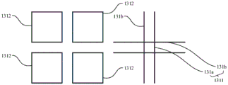
在一种可能的实施方式中,请一并参阅图6,图6为本申请另一实施方式提供的除膜单元图案示意图。所述第一除膜子单元1311包括第一除膜部131a及由所述第一除膜部131a延伸而出的多个第二除膜部131b,所述第一除膜部131a设置于多个所述第二除膜子单元1312之间的间隙,且分别与多个所述第二除膜子单元1312相连,多个所述第二除膜部131b分别与对应的所述第二除膜子单元1312的周缘至少部分重叠设置。In a possible implementation manner, please refer to FIG. 6 together. FIG. 6 is a schematic diagram of a pattern of a film removal unit provided in another implementation manner of the present application. The first
具体的,所述第一除膜部131a内切于多个所述第二除膜子单元1312,也就是说,所述第一除膜部131a与多个所述第二除膜子单元1312均没有重叠的部分,且由所述第一除膜部131a的每个所述第二除膜部131b均分别与所述第二除膜子单元1312对应的周缘至少部分重叠设置。Specifically, the first
为了更好的观察本实施方式中所述第一除膜子单元1311与所述第二除膜子单元1312的设计图案,请一并参阅图7,图7为本申请一实施方式提供的第一除膜子单元与第二除膜子单元的图案示意图。具体的,如图7所示,所述第一除膜子单元1311整体上以“井”字型分布,多个所述第二除膜子单元1312形成间隔设置的多个正方形。所述第一除膜部131a为“井”字型中间的小正方形,所述第二除膜部131b由所述第一除膜部131a的小正方形的边长延伸形成。在本实施方式中,相邻且垂直的所述第二除膜部131b,与对应的一个所述第二除膜子单元1312相邻的两边重叠设置。In order to better observe the design patterns of the first
需要说明的是,每个所述第二除膜部131b由所述第一除膜部131a的各个边长沿相反的方向延伸形成,且每个所述第二除膜部131b的延伸长度、宽度均可以是不同的。在其他可能的实施方式中,只要不影响所述第一除膜子单元1311与所述第二除膜子单元1312的至少部分重叠设置,本申请对所述第一除膜子单元1311与所述第二除膜子单元1312的形状也不加以限制。It should be noted that each of the second
在本实施方式中,如图6所示,所述第二除膜子单元1312对应的所述透明板11部分用于通过较高频段的电磁波信号,而所述第一除膜子单元1311对应的所述透明板11部分能够通过较低频段的电磁波信号,也就是说,所述第二除膜部131b与所述第二除膜子单元1312重叠设置的部分能够同时通过较高以及较低频段的电磁波信号。In this embodiment, as shown in FIG. 6 , the part of the
需要补充说明的是,与图4相比,当本实施例的膜层12用于导热和/或导电功能时,由于除膜单元131的外周不封闭,因此除膜单元131内周的膜层12可以与除膜单元131外周的膜层12连通,整体膜层12的导热性和/或导电性更佳。It should be added that, compared with FIG. 4 , when the
具体的,请一并参阅图8,图8为本申请另一实施方式提供的覆膜板总成衰减性能示意图。如图8所示,其横坐标为通过所述覆膜板总成1的电磁波信号的频段,纵坐标为通过后的电磁波信号的衰减量。结合图8的结果可以得出,本实施方式的所述除膜单元131的图案设计,可以使得所述覆膜板总成1按此方式除膜后,满足移动5G双频段(2.6GHz、4.9GHz)的通信功能。在2515MHz-2675MHz、4800MHz-4900MHz相对于未设置所述膜层12的玻璃衰减小于5dB,满足了镀膜玻璃对车载5G信号的通透要求。Specifically, please refer to FIG. 8 together. FIG. 8 is a schematic diagram of attenuation performance of a film-coated panel assembly provided in another embodiment of the present application. As shown in FIG. 8 , the abscissa is the frequency band of the electromagnetic wave signal passing through the film-coated
在一种可能的实施方式中,请再次参阅图4,多个所述第二除膜子单元1312之间的间隙为W1,所述第一除膜子单元1311的其中一边与所述除膜单元131对应的一边的距离为W2,且满足W1=K*W2,其中K值介于1.5-2.5之间。In a possible implementation manner, please refer to FIG. 4 again, the gap between the plurality of second
具体的,当满足W1=K*W2时,所述第一除膜子单元1311对应的所述透明板11部分以及所述第二除膜子单元1312对应的所述透明板11部分的谐振性能最优。所谓谐振是指,当两个电磁波信号的频段相同或较为接近,且距离合适时,两个电磁波信号将产生谐振,以使得电磁波信号的辐射强度更强。在本实施方式中,优选的,K取值为2。Specifically, when W 1 =K*W 2 is satisfied, the part of the
可以理解的,当W1≠K*W2时,所述第一除膜子单元1311对应的所述透明板11部分将使得较低频段的电磁波信号产生谐振,而所述第二除膜子单元1312对应的所述透明板11部分将使得较高频段的电磁波信号产生谐振,以兼顾高低频电磁波信号的谐振性能。It can be understood that when W 1 ≠K*W 2 , the part of the
在一种可能的实施方式中,请再次参阅图4及图6,当所述除膜单元131为D外边长范围为4mm-20mm的正方形时,其中K值介于1.8-2.2之间。In a possible implementation manner, please refer to FIG. 4 and FIG. 6 again, when the
在本实施方式中,优选的,所述除膜单元131为D外边长为12mm,所述第一除膜子单元1311为L1外边长11.6mm的正方形,所述第二除膜子单元1312为L2外边长5.4mm的正方形。In this embodiment, preferably, the
具体的,所述除膜单元131的D外边长,所述第一除膜子单元1311的L1外边长以及所述第二除膜子单元1312的L2外边长如图4及图6所示。可以理解的,上述数值是以较低除膜面积比实现的,激光大面积除膜方案量产的一种应用。在其他可能的实施方式中,所述除膜单元131的D外边长,所述第一除膜子单元1311的L1外边长以及所述第二除膜子单元1312的L2外边长还可以是其他数值,本申请对此不加以限制。Specifically, the D outer side length of the
在一种可能的实施方式中,W1的范围为0.1mm-4mm,W2的范围为0.05mm-2mm。In a possible implementation manner, the range of W 1 is 0.1mm-4mm, and the range of W 2 is 0.05mm-2mm.
优选的,本实施方式中的W1为0.8mm,W2为0.4mm,是根据上文所述除膜单元131的D外边长,所述第一除膜子单元1311的L1外边长以及所述第二除膜子单元1312的L2外边长计算得出的优选数值。当所述除膜单元131的D外边长,所述第一除膜子单元1311的L1外边长以及所述第二除膜子单元1312的L2外边长改变时,W1及W2的数值也可能发生改变,本申请对此不加以限制。Preferably, in this embodiment, W1 is 0.8 mm, and W2 is 0.4 mm, which is based on the length of the outer edge D of the membrane-removing
在一种可能的实施方式中,请一并参阅图9,图9为本申请另一实施方式提供的除膜单元图案示意图。所述除膜单元131在所述膜层12的投影形状为圆形或多边形中的任意一种或多种。In a possible implementation manner, please also refer to FIG. 9 , which is a schematic diagram of a pattern of a film removal unit provided in another implementation manner of the present application. The projection shape of the
具体的,如图9所示,所述除膜单元131在所述膜层12的投影形状为圆形,可以理解的,所述除膜单元131的投影形状对通过的电磁波信号的频段、谐振以及除膜面积比均有影响。只要不影响所述除膜单元131占所述除膜区13的面积比值小于或等于10%,本申请对所述除膜单元131在所述膜层12的投影形状不加以限制。Specifically, as shown in FIG. 9 , the projected shape of the
需要说明的是,本申请提供的所述覆膜板总成1满足了镀膜玻璃产品对双频信号的通讯需求,如WIFI双频段2.4GHz、5.8GHz,中国移动5G双频段2.6GHz、4.8GHz,或者兼顾ETC、V2X、5G的组合应用。It should be noted that the
本申请还提供了一种车辆2,请一并参阅图10,图10为本申请一实施方式提供的车辆俯视示意图。所述车辆2包括如上文所述的覆膜板总成1。The present application also provides a
具体的,所述车辆2还包括车架21,所述覆膜板总成1安装于所述车架21上。可以理解的,当所述覆膜板总成1应用于车辆2上时,所述覆膜板总成1可以应用于车辆2的前挡风玻璃、天窗玻璃、侧窗玻璃、后挡玻璃等夹层产品中,本申请对此不加以限制。所述覆膜板总成1请参阅上文描述,在此不再赘述。Specifically, the
需要说明的是,所述覆膜板总成1还可以应用于其他场景,例如,在建筑领域应用于中空幕墙低辐射玻璃、带通讯功能的电子设备等,本申请对此不加以限制。It should be noted that the film-coated
本文中应用了具体个例对本申请的原理及实施方式进行了阐述,以上实施例的说明只是用于帮助理解本申请的核心思想;同时,对于本领域的一般技术人员,依据本申请的思想,在具体实施方式及应用范围上均会有改变之处,综上所述,本说明书内容不应理解为对本申请的限制。In this paper, specific examples are used to illustrate the principle and implementation of the application. The description of the above embodiments is only used to help understand the core idea of the application; meanwhile, for those of ordinary skill in the art, according to the thinking of the application, There will be changes in specific implementation methods and application ranges. To sum up, the content of this specification should not be construed as limiting the application.
Claims (13)
Priority Applications (1)
| Application Number | Priority Date | Filing Date | Title |
|---|---|---|---|
| CN202110765096.0A CN113682009B (en) | 2021-07-06 | 2021-07-06 | Tectorial membrane board assembly and vehicle |
Applications Claiming Priority (1)
| Application Number | Priority Date | Filing Date | Title |
|---|---|---|---|
| CN202110765096.0A CN113682009B (en) | 2021-07-06 | 2021-07-06 | Tectorial membrane board assembly and vehicle |
Publications (2)
| Publication Number | Publication Date |
|---|---|
| CN113682009A CN113682009A (en) | 2021-11-23 |
| CN113682009B true CN113682009B (en) | 2023-04-07 |
Family
ID=78576750
Family Applications (1)
| Application Number | Title | Priority Date | Filing Date |
|---|---|---|---|
| CN202110765096.0A Active CN113682009B (en) | 2021-07-06 | 2021-07-06 | Tectorial membrane board assembly and vehicle |
Country Status (1)
| Country | Link |
|---|---|
| CN (1) | CN113682009B (en) |
Cited By (1)
| Publication number | Priority date | Publication date | Assignee | Title |
|---|---|---|---|---|
| WO2025168573A1 (en) * | 2024-02-09 | 2025-08-14 | Agc Glass Europe | Glazing unit and associated decoating method |
Citations (3)
| Publication number | Priority date | Publication date | Assignee | Title |
|---|---|---|---|---|
| CN101056828A (en) * | 2004-11-10 | 2007-10-17 | 日本板硝子株式会社 | Curved laminated glass for vehicle and vehicle fixed with the curved laminated glass |
| WO2016173058A1 (en) * | 2015-04-28 | 2016-11-03 | 罗森伯格技术(昆山)有限公司 | Multi-frequency antenna |
| CN112153833A (en) * | 2019-06-28 | 2020-12-29 | Oppo广东移动通信有限公司 | Housing assembly, antenna device and electronic equipment |
Family Cites Families (14)
| Publication number | Priority date | Publication date | Assignee | Title |
|---|---|---|---|---|
| JP2011102217A (en) * | 2009-11-11 | 2011-05-26 | Asahi Glass Co Ltd | Heat ray reflecting glass plate, and method for bending the heat ray reflecting glass plate |
| EP2586610B1 (en) * | 2011-10-27 | 2014-05-07 | Saint-Gobain Glass France | Sheet with high frequency transmission |
| CN104583146B (en) * | 2012-08-28 | 2017-02-22 | 法国圣戈班玻璃厂 | Coated pane having areas in which the coating is partially removed |
| ES2707776T3 (en) * | 2012-10-15 | 2019-04-05 | Saint Gobain | Luna with high frequency transmission |
| US8927069B1 (en) * | 2013-10-02 | 2015-01-06 | Eritek, Inc. | Method and apparatus for improving radio frequency signal transmission through low-emissivity coated glass |
| WO2015091016A1 (en) * | 2013-12-16 | 2015-06-25 | Saint-Gobain Glass France | Heatable pane with high-frequency transmission |
| CN106273881B (en) * | 2015-05-29 | 2019-06-21 | 法国圣戈班玻璃公司 | Low-emissivity glass, method for manufacturing the same, and vehicle window |
| AT517932B1 (en) * | 2015-10-16 | 2018-03-15 | Siemens Ag Oesterreich | Conductively coated window pane, in particular for rail vehicles |
| KR102570124B1 (en) * | 2016-10-18 | 2023-08-23 | 삼성전자 주식회사 | Film laminate and window product including the film laminate |
| EP3778275A4 (en) * | 2018-03-27 | 2022-03-16 | Nippon Sheet Glass Company, Limited | VEHICLE GLASS AND METHOD FOR MANUFACTURING VEHICLE GLASS |
| CN113454845A (en) * | 2019-02-13 | 2021-09-28 | 旭硝子欧洲玻璃公司 | Glazing unit with frequency selective coating and method |
| PE20220735A1 (en) * | 2019-08-28 | 2022-05-05 | Saint Gobain | PANEL WITH PATTERN FOR HIGH FREQUENCY TRANSMISSION |
| CN110698076A (en) * | 2019-11-14 | 2020-01-17 | 武汉长利新材料科技有限公司 | Method for manufacturing coated glass of front windshield automobile |
| CN112829400A (en) * | 2021-02-03 | 2021-05-25 | 中国科学院上海硅酸盐研究所 | A structure/stealth integrated composite material and preparation method thereof |
-
2021
- 2021-07-06 CN CN202110765096.0A patent/CN113682009B/en active Active
Patent Citations (3)
| Publication number | Priority date | Publication date | Assignee | Title |
|---|---|---|---|---|
| CN101056828A (en) * | 2004-11-10 | 2007-10-17 | 日本板硝子株式会社 | Curved laminated glass for vehicle and vehicle fixed with the curved laminated glass |
| WO2016173058A1 (en) * | 2015-04-28 | 2016-11-03 | 罗森伯格技术(昆山)有限公司 | Multi-frequency antenna |
| CN112153833A (en) * | 2019-06-28 | 2020-12-29 | Oppo广东移动通信有限公司 | Housing assembly, antenna device and electronic equipment |
Cited By (1)
| Publication number | Priority date | Publication date | Assignee | Title |
|---|---|---|---|---|
| WO2025168573A1 (en) * | 2024-02-09 | 2025-08-14 | Agc Glass Europe | Glazing unit and associated decoating method |
Also Published As
| Publication number | Publication date |
|---|---|
| CN113682009A (en) | 2021-11-23 |
Similar Documents
| Publication | Publication Date | Title |
|---|---|---|
| US12071810B2 (en) | Glazing unit with frequency selective coating and method | |
| Farooq et al. | Polarization-insensitive triband FSS for RF shielding at normal and higher temperatures by retrofitting on ordinary glass windows | |
| US12071368B2 (en) | Glazing unit with frequency selective coating and method | |
| CN113682009B (en) | Tectorial membrane board assembly and vehicle | |
| CN113423672B (en) | Flush-mounted glass unit with frequency selective coating and method | |
| Bagheri et al. | Enhancing 5G propagation into vehicles and buildings using optically transparent and polarisation insensitive metasurfaces over wide-incidence angles | |
| WO2023153328A1 (en) | Fresnel zone plate lens, glass pane having built-in fresnel zone plate lens, and glass pane equipped with fresnel zone plate lens | |
| Nasir et al. | A miniaturized and high optically transparent frequency selective surface for rf shielding using double-glazed glass windows for green building applications | |
| JP7292540B1 (en) | glass body | |
| JPH11195890A (en) | Novel conductive bipolar element pattern that reflects electromagnetic waves in a specific range of frequencies and frequency-selective electromagnetic shielding material having the same | |
| US11958768B2 (en) | Glazing unit with frequency selective coating and method | |
| Seng et al. | Investigation and enhancement of radio frequency signal losses of glassy window | |
| CN120237436B (en) | Double-layer complementary frequency selective surface with multi-band communication signal anti-reflection function | |
| Zhang et al. | A passive transparent metasurface based on low-emissivity glass | |
| Khalily et al. | Amirmasood Bagheri, Shadi Danesh, Fan Wang 2, Seyed Ehsan Hosseininejad | |
| CN217387546U (en) | Transparent low-loss absorption-permeability integrated frequency selective surface based on thin metal wires | |
| FI12276U1 (en) | Glazing | |
| CN117940389A (en) | Glass body | |
| CN121251224A (en) | Hollow glass component and preparation method thereof | |
| Ragulis et al. | Microwave transmission optimization of a modern glass window | |
| Zhuang et al. | Poster: PanoGlass: Optically Transparent Panoramic Metasurface for Sub-6 GHz Network | |
| WO2023060160A1 (en) | Electromagnetic communication enhancements through transparent conductive layers on a substrate | |
| WO2023060159A1 (en) | Electromagnetic communication enhancements through a coated transparent substrate | |
| JP2002171120A (en) | Radio wave converging structure and antenna device | |
| CN119038883A (en) | Low-emissivity glass for electromagnetic wave anti-reflection |
Legal Events
| Date | Code | Title | Description |
|---|---|---|---|
| PB01 | Publication | ||
| PB01 | Publication | ||
| SE01 | Entry into force of request for substantive examination | ||
| SE01 | Entry into force of request for substantive examination | ||
| GR01 | Patent grant | ||
| GR01 | Patent grant |