JP7292540B1 - glass body - Google Patents
glass body Download PDFInfo
- Publication number
- JP7292540B1 JP7292540B1 JP2022570664A JP2022570664A JP7292540B1 JP 7292540 B1 JP7292540 B1 JP 7292540B1 JP 2022570664 A JP2022570664 A JP 2022570664A JP 2022570664 A JP2022570664 A JP 2022570664A JP 7292540 B1 JP7292540 B1 JP 7292540B1
- Authority
- JP
- Japan
- Prior art keywords
- radio wave
- conductive film
- film
- glass
- less
- Prior art date
- Legal status (The legal status is an assumption and is not a legal conclusion. Google has not performed a legal analysis and makes no representation as to the accuracy of the status listed.)
- Active
Links
Images


Classifications
-
- C—CHEMISTRY; METALLURGY
- C03—GLASS; MINERAL OR SLAG WOOL
- C03C—CHEMICAL COMPOSITION OF GLASSES, GLAZES OR VITREOUS ENAMELS; SURFACE TREATMENT OF GLASS; SURFACE TREATMENT OF FIBRES OR FILAMENTS MADE FROM GLASS, MINERALS OR SLAGS; JOINING GLASS TO GLASS OR OTHER MATERIALS
- C03C17/00—Surface treatment of glass, not in the form of fibres or filaments, by coating
- C03C17/34—Surface treatment of glass, not in the form of fibres or filaments, by coating with at least two coatings having different compositions
- C03C17/36—Surface treatment of glass, not in the form of fibres or filaments, by coating with at least two coatings having different compositions at least one coating being a metal
-
- C—CHEMISTRY; METALLURGY
- C03—GLASS; MINERAL OR SLAG WOOL
- C03C—CHEMICAL COMPOSITION OF GLASSES, GLAZES OR VITREOUS ENAMELS; SURFACE TREATMENT OF GLASS; SURFACE TREATMENT OF FIBRES OR FILAMENTS MADE FROM GLASS, MINERALS OR SLAGS; JOINING GLASS TO GLASS OR OTHER MATERIALS
- C03C27/00—Joining pieces of glass to pieces of other inorganic material; Joining glass to glass other than by fusing
- C03C27/06—Joining glass to glass by processes other than fusing
-
- E—FIXED CONSTRUCTIONS
- E06—DOORS, WINDOWS, SHUTTERS, OR ROLLER BLINDS IN GENERAL; LADDERS
- E06B—FIXED OR MOVABLE CLOSURES FOR OPENINGS IN BUILDINGS, VEHICLES, FENCES OR LIKE ENCLOSURES IN GENERAL, e.g. DOORS, WINDOWS, BLINDS, GATES
- E06B3/00—Window sashes, door leaves, or like elements for closing wall or like openings; Layout of fixed or moving closures, e.g. windows in wall or like openings; Features of rigidly-mounted outer frames relating to the mounting of wing frames
- E06B3/66—Units comprising two or more parallel glass or like panes permanently secured together
- E06B3/663—Elements for spacing panes
Abstract
ガラス体(100)は、第1面と、第1面とは反対側の第2面(12)と、を有する第1ガラス板(1)を備え、第1面及び第2面(12)の少なくとも一方の板面は、直進性のある波長を有する電波が透過可能な電波透過領域(43)を含んでおり、電波透過領域(43)は、電波を通過させる互いに離間した複数の電波通過部(43A)と、隣り合う電波通過部(43A)の間で電波の遮断性がある導電膜が形成された導電膜部(43B)と、を有しており、電波透過領域(43)は、複数の電波通過部(43A)を通過した電波の一部が回折して導電膜部(43B)と対向する空間で重なり合う電波拡散構造で構成されている。A glass body (100) comprises a first glass plate (1) having a first side and a second side (12) opposite the first side, the first side and the second side (12) includes a radio wave transmission area (43) through which radio waves having a straight wavelength can pass, and the radio wave transmission area (43) comprises a plurality of mutually spaced radio wave transmission areas through which radio waves pass. a portion (43A) and a conductive film portion (43B) formed with a conductive film that blocks radio waves between adjacent radio wave passage portions (43A), and the radio wave transmission region (43) is , a plurality of radio wave passing portions (43A), part of which is diffracted and overlapped in a space facing the conductive film portion (43B).
Description
本発明は、ガラス体に関する。 The present invention relates to glass bodies.
車両や建物の窓ガラスの板面にLow-E膜(低放射膜)が形成された、断熱性又は遮熱性を有するガラス体が知られている(例えば、特許文献1参照)。このLow-E膜は、数百MHz~数十GHzの周波数帯域の電波に対して透過性が低い(遮断性を有する)といった問題がある。 BACKGROUND ART A heat-insulating or heat-insulating glass body having a Low-E film (low-emissivity film) formed on a plate surface of a window glass of a vehicle or building is known (see, for example, Patent Document 1). This Low-E film has a problem that it has low permeability (has blocking properties) for radio waves in a frequency band of several hundred MHz to several tens of GHz.
そこで、特許文献2に記載のガラス体は、平行な複数の線で構成される開口部をLow-E膜に設けており、この複数の線の長さとLow-E膜の面積との比率を規定することで、数百MHz~数十GHzの周波数帯域の電波に対して電波透過性を高めている。
Therefore, in the glass body described in
また、特許文献3に記載のガラス体は、不連続な複数の島からなるLow-E膜を有する第1膜領域に設けており、この第1膜領域が電波透過性を有している。また、特許文献3には、第1ガラス板の第2面に第1膜領域を設け、第2ガラス板の第4面のうち第1膜領域に対向する位置にアンテナを設けた複層ガラスパネルの実施形態が開示されている。
Further, the glass body described in
第4世代移動通信システム(以下、「4G」という)及び第5世代移動通信システム(以下、「5G」という)で使用される周波数帯域に含まれる700MHz~30GHzの電波はそれより低い周波数帯の電波と比較して直進性が高く、特許文献2に記載の開口部や特許文献3に記載の第1膜領域は、この電波の直進性を担保する形状に設定されている。特に、特許文献2に記載の開口部は、平行な複数の線をLow-E膜に設けているため、縞模様として視認されやすく、外観上の影響が大きくなってしまう。また、4Gや5Gは直進性が高いため、室内側において、屋外の基地局から飛来する電波に対して該開口部に対向する空間以外では電波が弱くなりやすく、電波を受信し難いといった問題がある。このため、直進性が高い電波における室内側の通信環境の改善が必要となる。
Radio waves of 700 MHz to 30 GHz included in the frequency band used in the 4th generation mobile communication system (hereinafter referred to as "4G") and the 5th generation mobile communication system (hereinafter referred to as "5G") are in the lower frequency band The straightness of radio waves is higher than that of radio waves, and the opening described in
そこで、受信エリアを拡げることが可能な電波透過性を有するガラス体が望まれている。 Therefore, there is a demand for a glass body having radio wave transparency that can expand the reception area.
本発明に係るガラス体の特徴構成は、第1面と、当該第1面とは反対側の第2面と、を有する第1ガラス板を備え、前記第1面及び前記第2面の少なくとも一方の板面は、直進性のある波長を有する電波が透過可能な電波透過領域を含んでおり、前記電波透過領域は、前記電波を通過させる互いに離間した複数の電波通過部と、隣り合う前記電波通過部の間で前記電波の遮断性がある導電膜が形成された導電膜部と、を有しており、前記電波透過領域は、複数の前記電波通過部を通過した前記電波の一部が回折して前記導電膜部と対向する空間で重なり合う電波拡散構造で構成されている点にある。 A glass body according to the present invention includes a first glass plate having a first surface and a second surface opposite to the first surface, and at least one of the first surface and the second surface One of the plate surfaces includes a radio wave transmitting area through which radio waves having a straight wavelength can pass, and the radio wave transmitting area includes a plurality of mutually spaced radio wave passing portions for passing the radio waves, and the adjacent radio wave passing portions. and a conductive film portion in which the conductive film having the radio wave shielding property is formed between the radio wave passing portions, and the radio wave transmitting region is a portion of the radio waves that have passed through the plurality of the radio wave passing portions. diffracts and overlaps in the space facing the conductive film portion.
上述したように、例えば4Gの周波数帯域である700MHz~3.5GHzの電波や5Gの周波数帯域である3.6GHz~30GHzの電波は直進性が高く、ガラス体を通過する電波は、第1ガラス板の導電膜のない領域に対向する範囲内において電波強度が高くなる。一方、電波受信エリアを大きくするために、ガラス体に導電膜を設けなければ良いが、その場合は、断熱性や遮熱性(以下、「断熱性能」という)が無くなり、断熱性能と電波透過性とのトレードオフの関係にあった。 As described above, for example, radio waves of 700 MHz to 3.5 GHz, which is the frequency band of 4G, and radio waves of 3.6 GHz to 30 GHz, which is the frequency band of 5G, have high straightness. The radio wave intensity increases in the range facing the area of the plate without the conductive film. On the other hand, in order to increase the radio wave reception area, it is better not to provide a conductive film on the glass body, but in that case, the heat insulation and heat shielding properties (hereinafter referred to as "heat insulation performance") will be lost, and the heat insulation performance and radio wave permeability will be lost. There was a trade-off relationship with
本構成のガラス体は、電波透過領域において、電波を通過させる互いに離間した複数の電波通過部を設け、隣り合う電波通過部の間に導電膜部を設けている。つまり、電波透過領域においても導電膜部を設けることにより、断熱性能を高め、複数の電波通過部を設けることにより、電波透過性を高めている。 The glass body of this configuration is provided with a plurality of spaced apart radio wave passing portions for passing radio waves in the radio wave transmitting region, and a conductive film portion is provided between the adjacent radio wave passing portions. In other words, even in the radio wave transmitting region, the heat insulation performance is enhanced by providing the conductive film portion, and radio wave transparency is enhanced by providing a plurality of radio wave passing portions.
さらに、本構成の電波透過領域は、複数の電波通過部を通過した電波の一部が回折して導電膜部と対向する空間で重なり合う電波拡散構造で構成されている。つまり、電波通過部を通過した電波が直進するだけでなく回折し、電波回折成分が導電膜部と対向する空間で重なり合う。これにより、電波強度が弱くなりやすい導電膜部と対向する空間において、電波強度を高めることが可能となり、電波受信エリアを大きくすることができる。このように、受信エリアを拡げることが可能な電波透過性を有するガラス体となっている。 Further, the radio wave transmission region of this configuration is configured with a radio wave diffusion structure in which a part of the radio wave that has passed through the plurality of radio wave passage portions is diffracted and overlapped in the space facing the conductive film portion. In other words, the radio wave that has passed through the radio wave passing portion not only travels straight but also diffracts, and the radio wave diffraction components overlap in the space facing the conductive film portion. As a result, the radio wave intensity can be increased in the space facing the conductive film portion where the radio wave intensity tends to be weak, and the radio wave reception area can be enlarged. In this way, the glass body has radio wave transparency that can expand the reception area.
他の特徴構成として、前記電波通過部は、中心を通る線分の最大長が、前記波長の4倍以下である点にある。 Another characteristic configuration is that the radio wave passing portion has a maximum length of a line segment passing through the center that is four times or less the wavelength.
例えば、電波通過部が矩形状であり、一辺の長さが100mmであれば、波長が25mm以上(周波数帯が約12GHz以下)の電波回折成分が増加するとの知見を得た。本構成のように、電波通過部の中心を通る線分の最大長を波長の4倍以下とすれば、使用する周波数帯域に応じて、広い受信エリアで電波強度を高めることが可能な電波通過部の寸法を決定することができる。 For example, it has been found that if the radio wave passing portion is rectangular and the length of one side is 100 mm, the radio wave diffraction component with a wavelength of 25 mm or more (frequency band of about 12 GHz or less) increases. As in this configuration, if the maximum length of the line segment passing through the center of the radio wave passing part is set to four times or less than the wavelength, the radio wave passing can increase the radio wave intensity in a wide reception area according to the frequency band used. The dimensions of the part can be determined.
他の特徴構成として、隣り合う前記電波通過部の最短距離となる前記導電膜部の幅は、10mm以上500mm以下である点にある。 Another characteristic configuration is that the width of the conductive film portion, which is the shortest distance between the adjacent radio wave passing portions, is 10 mm or more and 500 mm or less.
本構成のように、隣り合う電波通過部の最短距離となる導電膜部の幅が10mm以上500mm以下であれば、断熱性能と電波透過性とを両立させることができる。なお、導電膜部の幅が10mmより小さい場合、導電膜部による電波遮断性が低下して電波透過領域全体が一体的な電波透過性を有することとなるため、電波回折成分が低下し、導電膜部の幅が500mmよりも大きい場合、第1ガラス板の近傍空間で電波の重なりが無いデッドスペースが生じ易くなる。 As in this configuration, if the width of the conductive film portion, which is the shortest distance between the adjacent radio wave passing portions, is 10 mm or more and 500 mm or less, both heat insulation performance and radio wave transparency can be achieved. If the width of the conductive film portion is less than 10 mm, the radio wave shielding property of the conductive film portion is reduced, and the entire radio wave transmission region has integral radio wave transparency. If the width of the film portion is greater than 500 mm, a dead space in which radio waves do not overlap is likely to occur in the vicinity of the first glass plate.
他の特徴構成として、前記少なくとも一方の板面は、前記電波透過領域の周囲に前記導電膜が形成された電波非透過領域を含んでおり、前記電波通過部には、互いに離間した前記導電膜で覆われた複数の島を有するパターニングが形成されている点にある。 As another characteristic configuration, the at least one plate surface includes a radio wave non-transmitting region in which the conductive film is formed around the radio wave transmitting region, and the radio wave passing portion includes the conductive films spaced apart from each other. A patterning having a plurality of islands covered with is formed.
本構成のように、電波通過部に、互いに離間した導電膜で覆われた複数の島を有するパターニングが形成されていれば、電波非透過領域と電波透過領域との間で外観上の影響を小さくすることができる。 As in this configuration, if a pattern having a plurality of islands covered with a conductive film separated from each other is formed in the radio wave passing portion, there is no influence on the appearance between the radio wave non-transmitting region and the radio wave transmitting region. can be made smaller.
他の特徴構成として、隣り合う前記島の間には、1μm以上100μm以下の線幅を有する細線が形成されており、隣り合う前記細線の間隔が200μm以上10mm以下である点にある。 Another characteristic configuration is that a thin line having a line width of 1 μm or more and 100 μm or less is formed between the adjacent islands, and the distance between the adjacent thin lines is 200 μm or more and 10 mm or less.
本構成のように、隣り合う島の間には、1μm以上100μm以下の線幅を有する細線が形成されており、隣り合う細線の間隔が200μm以上10mm以下であれば、電波透過性を担保しつつ、外観上の影響を小さくすることができる。なお、細線の線幅が1μmより小さくなれば隣り合う島と島の絶縁が取り難くなるため電波透過性の確保が難しくなり、100μmより大きくなれば、断熱性能が低下しやすくなる。また、隣り合う細線の間隔が200μmより小さくなれば、断熱性能が低下し、10mmより大きくなれば、電波透過性が低下しやすくなる。 As in this configuration, thin lines having a line width of 1 μm or more and 100 μm or less are formed between adjacent islands, and if the distance between adjacent thin lines is 200 μm or more and 10 mm or less, radio wave transmission is ensured. while reducing the influence on the appearance. If the line width of the thin wire is less than 1 μm, it becomes difficult to insulate adjacent islands, making it difficult to ensure radio wave transmission. Also, if the distance between adjacent thin wires is less than 200 μm, the heat insulation performance is lowered, and if it is more than 10 mm, the radio wave transmittance tends to be reduced.
他の特徴構成として、前記島は、矩形状である点にある。 Another feature is that the islands are rectangular.
本構成のように島が矩形状であれば、パターニング加工が容易である。 If the island has a rectangular shape as in this configuration, the patterning process is easy.
他の特徴構成として、前記波長は、10mm以上428mm以下である点にある。 Another feature is that the wavelength is 10 mm or more and 428 mm or less.
本構成のように波長が10mm以上428mm以下(周波数帯が700MHz以上30GHz以下)であれば、特に直進性が高くなるため、上記構成のガラス体を採用することによる有用性を高めることができる。 If the wavelength is 10 mm or more and 428 mm or less (the frequency band is 700 MHz or more and 30 GHz or less) as in this configuration, the linearity is particularly high, so that the usefulness of using the glass body with the above configuration can be enhanced.
他の特徴構成として、前記導電膜は、Low-E膜である点にある。 Another feature is that the conductive film is a Low-E film.
本構成のように導電膜をLow-E膜とすれば、断熱性能を高めつつ、受信エリアを拡げることが可能な電波透過性を担保できる。 By using a Low-E film as the conductive film as in this configuration, it is possible to ensure radio wave transparency capable of expanding the receiving area while improving the heat insulation performance.
他の特徴構成として、前記第2面に対向する第3面と、当該第3面とは反対側の第4面と、を有する第2ガラス板と、前記第2面と前記第3面とに接触し、前記第1ガラス板と前記第2ガラス板との間に空隙層を形成するスペーサと、を更に備え、前記電波透過領域は、前記第2面又は前記第3面に形成されている点にある。 As another characteristic configuration, a second glass plate having a third surface facing the second surface and a fourth surface opposite to the third surface, the second surface and the third surface and forming a gap layer between the first glass plate and the second glass plate, wherein the radio wave transmitting region is formed on the second surface or the third surface. at the point where
本構成のような複層ガラスにおいて、第1ガラス板の第2面、又は、第2ガラス板の第3面にLow-E膜を配置すれば断熱性能が高まる。この断熱性能を高めたガラス体において、電波透過領域を第2面又は第3面に形成すれば、上記構成のガラス体を採用することによる有用性を高めることができる。 In the multi-layered glass of this configuration, if the Low-E film is arranged on the second surface of the first glass plate or the third surface of the second glass plate, the heat insulating performance is enhanced. In the glass body with improved heat insulating performance, if the radio wave transmission region is formed on the second surface or the third surface, the usefulness of the glass body having the above configuration can be enhanced.
以下に、本発明に係るガラス体の実施形態について、図面に基づいて説明する。ただし、以下の実施形態に限定されることなく、その要旨を逸脱しない範囲内で種々の変形が可能である。 An embodiment of the glass body according to the present invention will be described below with reference to the drawings. However, without being limited to the following embodiments, various modifications are possible without departing from the scope of the invention.
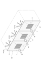
本実施形態におけるガラス体100は、種々の用途に用いることができ、例えば、建物の窓ガラス、自動車、航空機、船舶、列車などの移動体の窓ガラスとして用いることができる。図1には、ガラス体100を建物の窓ガラスに用いた模式図が示されている。なお、ガラス体100は、外気と接する窓ガラスであっても良いし、室内を区画する窓ガラスであっても良い。
The
図1に示すように、ガラス体100は、板面が矩形の外形を有する第1ガラス板1を備えている。ガラス体100は、直進性を有する4Gの周波数帯域である700MHz~3.5GHz(波長428mm~85mm)や5Gの周波数帯域3.6GHz~30GHz(波長83mm~10mm)の全帯域または一部の帯域に対応する電波が透過可能な電波透過領域43と、電波透過領域43の周囲にLow-E膜41(導電膜の一例)が形成された電波非透過領域42とを含んでいる。本実施形態における電波透過領域43は、電波の一部が回折して電波受信エリアを拡げる電波拡散構造となっている。電波透過領域43の詳細は後述する。
As shown in FIG. 1, the
第1ガラス板1(後述する第2ガラス板2も同様)の材料は特には限定されず、公知のガラス板を用いることができる。例えば、熱線吸収ガラス、クリアガラス、グリーンガラス、UVグリーンガラス、ソーダライムガラスなど種々のガラス板を用いることができる。第1ガラス板1の厚みは、特には限定されないが、例えば、2~15mmであることが好ましく、2.5~8mmであることがさらに好ましい。
The material of the first glass plate 1 (the same applies to the
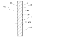
<第一実施形態:単板ガラス>
図2に示すように、第1ガラス板1は、第1面11と、第1面11とは反対側の第2面12とを有する。この第1ガラス板1の第2面12に、電波遮断性を有するLow-E膜41(導電膜の一例)が形成されている。Low-E膜41は、電波の遮断性がある導電性薄膜である。導電性薄膜の表面抵抗率は20Ω未満であると好ましい。こうすると、Low-E膜41は赤外域から電波域(数百MHz~数十GHzの周波数帯域)にわたる波長領域で高い反射率を有する。そのためLow-E膜41が形成されている第1ガラス板1の板面は、電波の透過性は低くなるが、放射率も低くなる。第1ガラス板1の第2面12に、Low-E膜41が全域に形成されている電波非透過領域42を有する。また、Low-E膜41が形成された板面である第2面12の一部(図では中央部分)に、Low-E膜41の一部がレーザ加工等により除去された電波透過領域43が設けられている。この電波透過領域43は、直進性を有する4Gの周波数帯域である700MHz~3.5GHz(波長428mm~85mm)や5Gの周波数帯域3.6GHz~30GHz(波長83mm~10mm)の全帯域または一部の帯域に対応する電波の透過を可能にするように配置される。なお、第1ガラス板1の第1面11に、電波非透過領域42及び電波透過領域43を設けても良い。<First Embodiment: Single Plate Glass>
As shown in FIG. 2 , the
<第二実施形態:複層ガラス>
図3に示すように、ガラス体100は、板面がほぼ同じ矩形の外形を有する2つのガラス板、つまり第1ガラス板1及び第2ガラス板2を有する複層ガラスである。一対のガラス板1,2は、その周縁部に配置されたスペーサ5によって互いに連結されている。スペーサ5により、一対のガラス板1,2間には空隙層3が形成される。第1ガラス板1は、室外側の板面である第1面11と、第1面11とは反対側の空隙層3側の板面である第2面12とを有する。第2ガラス板2は、空隙層3側の板面である第3面13と、第3面13とは反対側の室内側の板面である第4面14とを有する。つまり、スペーサ5は、第2面12と第3面13とに接触している。空隙層3の側の板面(第2面12)に、電波遮断性を有するLow-E膜41(導電膜の一例)が形成されている。なお、図示を省略するが、スペーサ5よりも外側に配置されたシール材が配置された枠体により、空隙層3は密閉されている。<Second embodiment: double glazing>
As shown in FIG. 3, the
第1ガラス板1の第2面12に、Low-E膜41が全域に形成されている電波非透過領域42を有する。また、Low-E膜41が形成された板面である第2面12に、Low-E膜41の一部がレーザ加工等により除去された電波透過領域43が設けられている。この電波透過領域43は、直進性を有する4Gの周波数帯域である700MHz~3.5GHz(波長428mm~85mm)や5Gの周波数帯域3.6GHz~30GHz(波長83mm~10mm)の全帯域または一部の帯域に対応する電波の透過を可能にするように配置される。なお、本実施形態のような複層ガラスにおいて、第1ガラス板1の第2面12、又は、第2ガラス板2の第3面13にLow-E膜41を配置すれば断熱性能が高まる。また、第1ガラス板1の第1面11又は第2ガラス板2の第4面14に、電波非透過領域42及び電波透過領域43を設けても良い。また、ガラス体100の室内側の板面(第4面14)に、電波送受信用のアンテナ(不図示)を設置してもよいし、室内の天井等にアンテナを設置しても良い。
The
<Low-E膜>
Low-E膜41は、本発明の目的を阻害しない限り特に限定されないが、好ましくは、銀を主成分とする層を含む多層膜である。また、Low-E膜41は、金属層、金属酸化物層、金属窒化物層および金属酸窒化物層から選ばれる2種以上の層を積層した多層からなるのも好ましい。金属層の好適な例としては銀層が挙げられる。金属酸化物層の好適な例としては、酸化スズ層、酸化チタン層または酸化亜鉛層が挙げられる。金属窒化物層の好適な例としては窒化ケイ素が挙げられる。金属酸窒化物層の好適な例としては酸窒化ケイ素が挙げられる。Low-E膜41は、物理的気相成長法(PVD)等の真空成膜法が好ましく、特にスパッタリング法が大面積を均一に成膜できるため好ましい。電波透過領域43は、例えば、スパッタリング法によりガラス板にLow-E膜41を成膜した後、レーザ加工等によりLow-E膜41を除去することで形成される。電波透過領域43は、各種のマスキング材を用いて形成してもよい。電波透過領域43は、このような手法で形成することで、ガラス板の所望の位置に容易に配置することができる。<Low-E film>
The Low-
また、Low-E膜41は、酸化スズ層、窒化ケイ素層、酸窒化ケイ素層、酸化チタン層、酸化亜鉛層および銀層から選ばれる3種以上の層を積層した多層からなるのがより好ましく、ガラス板表面から順次、(1)酸化スズ層(第1反射防止層)、酸化亜鉛層(第1反射防止層)、銀層(金属層)、酸化亜鉛層(第2反射防止層)および酸化スズ層(第2反射防止層)、(2)窒化ケイ素層(第1反射防止層)、酸化亜鉛層(第1反射防止層)、銀層(金属層)および酸化亜鉛層(第2反射防止層)を積層した3層または5層からなるのが最も好ましい。
Further, the Low-
Low-E膜41は、銀を主成分とする金属層を含有する。金属層の膜厚は5nm以上20nm以下であることが好ましく、10nm以上15nm以下であることが更に好ましい。Low-E膜41が、銀を主成分とする所定の膜厚の金属層を有することで、熱の放射を抑制することができる。これにより、ガラス体100は、断熱性能を向上させることができる。また、金属層の膜厚が15nm以下であることで、Low-E膜41による外観上の影響を小さくすることができる。
The Low-
Low-E膜41は、金属層の内側である、Low-E膜41が形成された板面に近い側に第1反射防止層を有し、第1反射防止層の光学膜厚の合計が20nm以上120nm以下であると好適である。Low-E膜41は、金属層の外側である、Low-E膜41が形成された板面から遠い側に第2反射防止層を有し、第2反射防止層の光学膜厚の合計が60nm以上120nm以下であると好適である。光学膜厚は、(屈折率n)×(膜厚d)によって算出することができる。第1反射防止層(第2反射防止層)が複数の膜によって構成される場合には、それぞれの膜で算出される光学膜厚の合計が第1反射防止層(第2反射防止層)の光学膜厚となる。光学膜厚を算出する上で、屈折率は可視光の波長により値が変動する。ここでは、可視光の波長を一般的な可視域の基準波長(550nm)の場合の屈折率に基づいた光学膜厚である。
The Low-
上記のように、Low-E膜41は、金属層を基準にして第1ガラス板1の第2面12に近い側に所定の膜厚の第1反射防止層が存在することで、金属層が保護されてLow-E膜41は低反射性能を有することになり、熱を確実に遮断することができる。また、ガラス体100において高い可視光透過率と好適な反射色調を実現できる。
As described above, the Low-
また、Low-E膜41は、金属層を基準にして第1ガラス板1の第2面12に遠い側に所定の膜厚の第2反射防止層が存在する場合においても、金属層が保護されてLow-E膜41は低反射性能を有することになり、熱を確実に遮断することができる。また、ガラス体100において高い可視光透過率と好適な反射色調を実現できる。
In addition, the Low-
<電波透過領域>
図4に示すように、本実施形態における電波非透過領域42は、電波透過領域43の周囲にLow-E膜41が形成された領域となっており、電波透過領域43は、電波の一部が回折して電波受信エリアを拡げる電波拡散構造となっている。電波透過領域43は、直進性のある波長(10mm~500mm)を有する電波を通過させる互いに離間した複数(本実施形態では5×5の25個)の電波通過部43Aと、隣り合う電波通過部43Aの間で電波遮断性があるLow-E膜41が形成された導電膜部43Bとを有している。この電波透過領域43は、複数の電波通過部43Aを通過した電波の一部が回折して導電膜部43Bと対向する空間で重なり合う電波拡散構造で構成されている。<Radio wave transmission area>
As shown in FIG. 4, the radio wave
本実施形態における電波通過部43Aは矩形状に形成されており、4辺のうち最も長い辺が、通過する電波の波長(10mm~500mm、以下、単に「波長」という)に対して4倍以下となっている。換言すると、電波通過部43Aは、中心を通る線分の最大長L(偏波となる電波の電界振動方向)が、波長の4倍以下である。このように、電波通過部43Aの中心を通る線分の最大長Lを波長の4倍以下とすれば、使用する周波数帯域に応じて、広い受信エリアで電波強度を高めることが可能な電波通過部43Aの寸法を決定することができる。一方、5G(ミリ波)の周波数帯域30GHz~300GHz(波長11mm未満)に対応する電波については、電波通過部43Aの加工が困難となるため、本実施形態に係る電波拡散構造として好ましくなく、通過する電波の波長を10mm以上としても良いし、5G(sub6帯)の波長49mm以上(周波数帯6GHz以下)に限定しても良い。なお、本実施形態では、電波通過部43Aが正方形であるため、4辺全て電波通過部43Aの中心を通る線分の最大長Lと等しくなるが、長方形である場合は、4辺のうち長い方の2辺が電波通過部43Aの中心を通る線分の最大長Lと等しくなる。
The radio
また、電波通過部43Aは、中心を通る線分の最大長Lが10mm以上、且つ、波長の4倍以下であることが好ましく、20mm以上、且つ、波長の2倍以下であることが更に好ましい。なお、電波通過部43Aの中心を通る線分の最大長Lは、10mmより下回ると、後述するパターニング加工が困難となり、波長の4倍を超えると電波回折成分が減少し、広い受信エリアで電波強度を高めることが困難となる。
The maximum length L of the line segment passing through the center of the radio
隣り合う電波通過部43Aの最短距離となる導電膜部43Bの幅Wは、10mm以上、且つ、500mm以下であることが好ましく、10mm以上、且つ、100mm以下であることが更に好ましい。このように、隣り合う電波通過部43Aの最短距離となる導電膜部43Bの幅Wが10mm以上500mm以下であれば、断熱性能と電波透過性とを両立させることができる。なお、導電膜部43Bの幅Wが10mmより小さい場合、導電膜部43Bによる電波遮断性が低下して電波透過領域43全体が一体的な電波透過性を有することとなるため、電波回折成分が低下し、導電膜部43Bの幅Wが500mmよりも大きい場合、第1ガラス板1の近傍空間で電波の重なりが無いデッドスペースが生じ易くなる。
The width W of the
夫々の電波通過部43Aには、互いに離間したLow-E膜41で覆われた複数の島43Aaを有するパターニングが形成されている。電波通過部43Aは、例えば、スパッタリング法によりガラス板にLow-E膜41を成膜した後、レーザ加工等によりLow-E膜41のみを除去することで、隣り合う島43Aaの間に細線43Abが形成される。
このように細線43Abを形成すれば、ガラス板に傷が付かず、細線43Abを目立たなくすることができる。本実施形態における複数の島43Aaは、同一の線幅を有する細線43Abを介して、互いに等間隔に離間したシンメトリー形状で形成されている。A pattern having a plurality of islands 43Aa covered with the Low-
By forming the thin wire 43Ab in this manner, the glass plate is not damaged, and the thin wire 43Ab can be made inconspicuous. A plurality of islands 43Aa in the present embodiment are formed in a symmetrical shape that is spaced apart from each other at equal intervals via fine lines 43Ab having the same line width.
この細線43Abの線幅は、1μm以上100μm以下であることが好ましく、5μm以上30μm以下であることが更に好ましい。細線43Abの線幅が1μmより小さくなれば一体的なLow-E膜41となって隣り合う島43Aaと島43Aaの絶縁が取り難くなるため電波透過性の確保が難しくなり、100μmより大きくなれば、断熱性能が低下しやすくなる。
The line width of the thin wire 43Ab is preferably 1 μm or more and 100 μm or less, more preferably 5 μm or more and 30 μm or less. If the line width of the fine wire 43Ab is smaller than 1 μm, it becomes difficult to insulate the adjacent islands 43Aa from each other by forming the integrated Low-
隣り合う細線43Abの間隔(隣り合う細線43Abの線中心間距離)は、200μm以上10mm以下であることが好ましく、500μm以上3mm以下であることが更に好ましい。また、隣り合う細線43Abの間隔が200μmより小さくなれば、断熱性能が低下し、10mmより大きくなれば、電波透過性が低下しやすくなる。なお、隣り合う細線43Abの間隔の上限値は、波長の3分の1以下であることが好ましい。 The interval between the adjacent thin wires 43Ab (distance between the line centers of the adjacent thin wires 43Ab) is preferably 200 μm or more and 10 mm or less, more preferably 500 μm or more and 3 mm or less. Further, if the interval between the adjacent fine wires 43Ab is less than 200 μm, the heat insulating performance is lowered, and if it is larger than 10 mm, the radio wave transmittance tends to be lowered. In addition, the upper limit of the interval between the adjacent thin wires 43Ab is preferably one-third or less of the wavelength.
<評価試験>
(試験条件)
第1ガラス板1の厚みが6mmのソーダライムガラスを用い、第2面12を覆うLow-E膜41は、第1ガラス板1の第2面12側から、SnO2/ZnO/Ag/SUS/ZnO/SnO2として、合計膜厚が80nm、放射率が0.1とした。Low-E膜41を除去するレーザ加工条件は、ガラスを除去すること無くLow-E膜41のみ除去できるように、YAG:Ndレーザを用いて、繰り返し周波数100kHz,波長355nm,操作速度300mm/secとした。<Evaluation test>
(Test condition)
A soda-lime glass having a thickness of 6 mm is used for the
(放射率)
フーリエ変換赤外分光度計(Perkin Elmer製 Frontier Gold)を用い、JIS-R3106に従い放射率を測定した。電波通過部43Aの個数及び大きさ、細線43Abの線幅及び間隔を変化させた場合における電波通過部43Aの放射率を表1に示す。電波通過部43A及び島43Aaを全て正方形で形成し、隣り合う電波通過部43Aの最短距離となる導電膜部43Bの幅を50mmに設定した。

Emissivity was measured according to JIS-R3106 using a Fourier transform infrared spectrophotometer (Frontier Gold manufactured by Perkin Elmer). Table 1 shows the emissivity of the radio
表1の試験番号(3)に示すように、細線43Abの線幅が100μmより大きくなれば、電波通過部43Aの放射率が著しく悪化し、断熱性能が低下することが理解できる。また、試験番号(1),(2),(4),(5),(6)に示すように、電波通過部43Aの個数や大きさに関わらず、細線43Abの線幅を100μm以下、且つ、細線43Abの間隔を200μm以上とすれば、第1ガラス板1の板面全域をLow-E膜41で覆う場合に比べて、放射率の悪化を抑制し、断熱性能が維持されることが理解できる。
As shown in Test No. (3) in Table 1, when the line width of the fine wire 43Ab is greater than 100 μm, the emissivity of the radio
(電波透過特性)
続いて、本実施形態におけるガラス体100の電波透過領域43は、電波の一部が回折して電波受信エリアを拡げる電波拡散構造となっていることを立証するシミュレーション結果について説明する。図5~図14には、本実施形態に係るガラス体100及び比較例に係るガラス体の電波透過特性を確認したシミュレーション結果が示されている。なお、図5~図8は、Micro-Stripes2高周波電磁界シミュレータを用い、図9~図14は、Altair Feko高周波電磁界シミュレータを用いた。また、図5~図12は、第1ガラス板1の第1面11に対して電波を垂直に入射させる垂直入射とし、図13及び図14は、第1ガラス板1の第1面11に対して電波を斜めに入射させる斜め入射とした。(Radio wave transmission characteristics)
Next, simulation results that prove that the radio
図5~図8には、電波透過領域43の電波通過部43Aとして、100mm×100mmの開口(中心を通る線分の最大長Lが100mm)を有する平面視(開口の上辺)から見たシミュレーション結果が示されている。この電波通過部43Aに対し、30GHz~1GHz(波長10mm~300mm)の電波を照射するシミュレーションを行った。図の破線で囲まれた領域が強い電波(入射する電波を0dBとしたときの電波透過損失10dB以下)の分布を示している。
5 to 8 show simulations viewed from a plan view (upper side of the opening) having an opening of 100 mm×100 mm (the maximum length L of a line segment passing through the center is 100 mm) as the radio
比較例としての図5に示すように、周波数帯が比較的高い30GHz~15GHz(波長10mm~20mm)においては、電波通過部43Aを通過した電波がほぼ回折すること無く直進していることが分かる。一方、本実施例としての図6に示すように、周波数帯が比較的低い10GHz~1GHz(波長30mm~300mm)においては、電波通過部43Aを通過した電波が導電膜部43Bに対向する空間まで拡がるように回折していることが分かる。
As shown in FIG. 5 as a comparative example, in the relatively high frequency band of 30 GHz to 15 GHz (wavelength 10 mm to 20 mm), the radio wave passing through the radio
図7~図8には、導電膜部43Bの幅Wを50mmに設定したときにおける隣り合う電波通過部43Aを通過した電波の重なり状況を示している。図7に示すように、周波数帯5GHz(波長60mm)では、導電膜部43Bに対向する空間で広い重なりを有しており、周波数帯10GHz(波長30mm)では、やや重なり度合が低下するものの、電波透過領域43は、複数の電波通過部43Aを通過した電波の一部が回折して導電膜部43Bと対向する空間で重なり合う電波拡散構造で構成されていることが理解できる。図8に示すように、周波数帯が低い3GHz~1GHz(波長100mm~300mm)では、導電膜部43Bに対向する空間で広い重なりを有している。これらから、電波の波長(30mm~300)が開口長さ100mm(中心を通る線分の最大長L)に対して、4分の1よりも大きいことが好ましいことが分かる。換言すると、電波通過部43Aは、波長の4倍以下であることが好ましい。なお、電波の波長(60mm~300mm)が開口長さ100mm(中心を通る線分の最大長L)に対して、2分の1よりも大きいことが更に好ましく、この場合、電波通過部43Aは波長の2倍以下となる。
FIGS. 7 and 8 show how radio waves passing through the adjacent radio
図9~図12には、第1ガラス板1の第1面11側から3.5GHzの周波数帯(波長86mm)を有する電波を垂直に入射させ、第1ガラス板1の第2面12から平行に1m離間した空間(図では2点鎖線)における電波の拡がりのシミュレーション結果が示されている。図9は、第1ガラス板1の第2面12の全体がLow-E膜41で覆われた比較例1を示し、図10は、第1ガラス板1の第2面12の中央のLow-E膜41を除去して形成された100mm×100mmの開口を1つ有する比較例2を示し、図11は、第1ガラス板1の第2面12の中央のLow-E膜41を除去して形成された500mm×500mmの開口を1つ有する比較例3を示している。図12は、上述した実施形態に係るガラス体100のように、100mm×100mmの電波通過部43Aを5×5個並べて合計500mm×500mmの電波透過領域43を第1ガラス板1の第2面12の中央に形成した本実施例を示している。
9 to 12, a radio wave having a frequency band of 3.5 GHz (wavelength 86 mm) is vertically incident from the
図9に示す比較例1では電波が遮断されており、電波透過損失が30dB以上であったため、第1ガラス板1の第2面12側では、ほとんど電波を受信できていない。図10に示す比較例2では開口から直進した電波のみであり、電波の拡がりが全く無かった。図11に示す比較例3では、500mmの開口長さであり、電波波長86mmに対して4倍以上であることから、電波の拡がりがほとんど無かった。一方、図12に示す本実施例では、電波透過損失が3dB以上15dB以下の範囲に拡がっており、電波強度がやや低下するものの、電波の受信エリアを拡大することができた。 In Comparative Example 1 shown in FIG. 9, radio waves were blocked and the radio wave transmission loss was 30 dB or more. In Comparative Example 2 shown in FIG. 10, only radio waves propagated straight from the opening, and there was no spreading of the radio waves. In Comparative Example 3 shown in FIG. 11, the opening length was 500 mm, which was four times or more the radio wave wavelength of 86 mm, so there was almost no spread of radio waves. On the other hand, in the present embodiment shown in FIG. 12, the radio wave transmission loss spreads over the range of 3 dB to 15 dB, and the radio wave reception area can be expanded although the radio wave intensity is slightly reduced.
図13及び図14には、第1ガラス板1を板面方向に4枚並べて配置した場合における電波の拡がりのシミュレーション結果が示されている。具体的には、図13及び図14では、3.5GHzの周波数帯(波長86mm)を有する電波を各々の第1ガラス板1の第1面11側から第2面12に向けて右向きの入射角45度で斜め入射させ、xy平面沿って水平方向に形成される領域R(図では2点鎖線)における電波の拡がりが示されている。領域Rは、4枚の第1ガラス板1が並べて配置される第1辺部Aと第1辺部Aに垂直となる第2辺部Bとによって形成される矩形領域である。図13及び図14では、第1辺部Aの長さが7800mmに設定され、第2辺部Bの長さが5500mmに設定されている。第1辺部Aに沿う複数の開口(電波透過領域43)は、第1辺部Aの両端から開口までの距離P1が900mmに設定され、隣接する開口間の距離P2が1800mmに設定されている。図13では、第1ガラス板1として第2面12の中央のLow-E膜41を除去して形成された500mm×500mmの開口を1つ有する比較例3のガラス体が用いられている。図14では、第1ガラス板1として、上述した実施形態に係るガラス体100のように、100mm×100mmの電波通過部43Aを5×5個並べて合計500mm×500mmの電波透過領域43を第2面12の中央に形成した本実施例のガラス体が用いられている。
FIGS. 13 and 14 show simulation results of the spread of radio waves when four
比較例3のガラス体が用いられた図13では、第1ガラス板1の開口を通過した夫々の電波はいずれも水平方向の拡がりが小さいため、電波が領域Rの半分程度しか行き渡らない。一方、本実施例のガラス体が用いられた図14では、電波透過領域43を通過した夫々の電波はいずれも水平方向の拡がりが大きいため、電波が領域Rに対して全体的に行き渡るようになった。以下、具体的に説明する。領域Rについて、左上の角から右下の角に向けて仮想の対角線Cを引き、領域Rのうち対角線Cに対して左側を第1領域R1とし右側を第2領域R2とする。この場合、図13では、第1ガラス板1の開口を通過した電波は、第1領域R1には行き渡るものの、第2領域R2のうち対角線Cから離れた領域には行き渡らない。一方、図14では、電波強度がやや低下するものの、電波が第1領域R1だけでなく第2領域R2にも広く行き渡り、電波が領域Rに対して全体的に行き渡ることが確認された。
In FIG. 13, in which the glass body of Comparative Example 3 is used, each radio wave that has passed through the opening of the
このように、本実施形態におけるガラス体100は、電波透過領域43において、電波を通過させる互いに離間した複数の電波通過部43Aを設け、隣り合う電波通過部43Aの間に導電膜部43Bを設けている。つまり、電波透過領域43においても導電膜部43Bを設けることにより、断熱性能を高め、複数の電波通過部43Aを設けることにより、電波透過性を高めている。
As described above, the
また、電波透過領域43は、複数の電波通過部43Aを通過した電波の一部が回折して導電膜部43Bと対向する空間で重なり合う電波拡散構造で構成されている。つまり、電波通過部43Aを通過した電波が直進するだけでなく回折し、電波回折成分が導電膜部43Bと対向する空間で重なり合う。これにより、電波強度が弱くなりやすい導電膜部43Bと対向する空間において、電波強度を高めることが可能となり、電波受信エリアを大きくすることができる。よって、受信エリアを拡げることが可能な電波透過性を有するガラス体100となっている。
Further, the radio
[その他の実施形態]
(1)上述した実施形態における電波透過領域43は、矩形状に限定されず、例えば、円形状、長円状、楕円状、十字形等であっても良い。この場合でも、電波通過部43Aは、中心を通る線分の最大長Lが10mm以上、且つ、波長の4倍以下であることが好ましい。
(2)図15に示すように、電波透過領域43の電波通過部43Aを円環状に形成しても良い。この場合でも、電波通過部43Aに複数の細線43Abを同心円状に等間隔で形成したパターニング加工が施されることが好ましい。電波透過領域43の各種寸法範囲は、上述した実施形態と同様である。
(3)上述した実施形態における電波通過部43Aに形成された複数の島43Aaを省略して、電波通過部43Aの全域に亘ってLow-E膜41を除去しても良い。また、島43Aaの形状も矩形状に限定されず、例えば、円形状、長円状、楕円状等であっても良い。
(4)電波透過領域43は、Low-E膜41を除去してガラス板を露出させる必要はなく、少なくとも銀を主成分とする金属層が除去されていれば良い。[Other embodiments]
(1) The radio
(2) As shown in FIG. 15, the radio
(3) The plurality of islands 43Aa formed in the radio
(4) The radio
(5)第二実施形態における複層ガラスにおいて、第1ガラス板1の第2面12に遮熱膜を配置し、第2ガラス板2の第3面13にLow-E膜41を配置しても良い。遮熱膜は、好ましくは、チタンの窒化物を主成分とする層を含む多層膜である。金属窒化物層の好適な例としては窒化チタン層が挙げられる。遮熱膜の膜厚は、積層される膜の種類により適宜選択されるが、通常、5~100nmであり、好ましくは10~50nmである。遮熱膜は、例えば熱線吸収膜によって構成されている。遮熱膜が熱線吸収膜であると、遮熱膜によって赤外線を吸収することができるので、ガラス体100において遮熱性を向上することができる。
(5) In the multi-layer glass of the second embodiment, the heat shield film is arranged on the
本発明は、建物の窓ガラス、自動車、航空機、船舶、列車などの移動体の窓ガラスとしてのガラス体に利用可能である。 INDUSTRIAL APPLICABILITY The present invention is applicable to glass bodies as window glass of buildings, and window glass of moving bodies such as automobiles, aircraft, ships, and trains.
1 :第1ガラス板
2 :第2ガラス板
3 :空隙層
5 :スペーサ
11 :第1面
12 :第2面
13 :第3面
14 :第4面
41 :Low-E膜(導電膜)
42 :電波非透過領域
43 :電波透過領域
43A :電波通過部
43Aa :島
43Ab :細線
43B :導電膜部
100 :ガラス体
L :中心を通る線分の最大長
W :導電膜部の幅
1: first glass plate 2: second glass plate 3: void layer 5: spacer 11: first surface 12: second surface 13: third surface 14: fourth surface 41: Low-E film (conductive film)
42: radio wave non-transmitting region 43: radio
Claims (6)
前記第1面及び前記第2面の少なくとも一方の板面は、直進性のある10mm以上500mm以下の波長を有する電波が透過可能な電波透過領域を含んでおり、
前記電波透過領域は、前記電波を通過させる互いに離間した複数の電波通過部と、隣り合う前記電波通過部の間で前記電波の遮断性がある導電膜が形成された導電膜部と、を有しており、
前記電波透過領域は、複数の前記電波通過部を通過した前記電波の一部が回折して前記導電膜部と対向する空間で重なり合う電波拡散構造で構成されており、
前記少なくとも一方の板面は、前記電波透過領域の周囲に前記導電膜が形成された電波非透過領域を含んでおり、
前記電波通過部には、互いに離間した前記導電膜で覆われた複数の島を有するパターニングが形成されており、
前記電波通過部は、中心を通る線分の最大長が、前記波長の4倍以下であり、
隣り合う前記電波通過部の最短距離となる前記導電膜部の幅は、10mm以上500mm以下であるガラス体。 A first glass plate having a first surface and a second surface opposite to the first surface,
At least one plate surface of the first surface and the second surface includes a radio wave transmission region through which radio waves having a straight wavelength of 10 mm or more and 500 mm or less can be transmitted,
The radio wave transmitting region has a plurality of radio wave passing portions separated from each other through which the radio wave passes, and a conductive film portion formed with the conductive film having the radio wave blocking property between the adjacent radio wave passing portions. and
The radio wave transmission region is configured with a radio wave diffusion structure in which a part of the radio wave that has passed through the plurality of radio wave passage portions is diffracted and overlaps in a space facing the conductive film portion,
said at least one plate surface includes a radio wave non-transmitting region in which said conductive film is formed around said radio wave transmitting region;
patterning having a plurality of islands covered with the conductive film separated from each other is formed in the radio wave passing portion ;
the maximum length of a line segment passing through the center of the radio wave passing portion is four times or less than the wavelength;
The glass body , wherein the width of the conductive film portion that is the shortest distance between the adjacent radio wave passing portions is 10 mm or more and 500 mm or less .
前記第2面と前記第3面とに接触し、前記第1ガラス板と前記第2ガラス板との間に空隙層を形成するスペーサと、を更に備え、
前記電波透過領域は、前記第2面又は前記第3面に形成されている請求項5に記載のガラス体。 a second glass plate having a third surface facing the second surface and a fourth surface opposite to the third surface;
a spacer that contacts the second surface and the third surface and forms a void layer between the first glass plate and the second glass plate;
6. The glass body according to claim 5 , wherein the radio wave transmission region is formed on the second surface or the third surface.
Priority Applications (1)
| Application Number | Priority Date | Filing Date | Title |
|---|---|---|---|
| JP2023090816A JP2023113772A (en) | 2021-09-06 | 2023-06-01 | glass body |
Applications Claiming Priority (3)
| Application Number | Priority Date | Filing Date | Title |
|---|---|---|---|
| JP2021144790 | 2021-09-06 | ||
| JP2021144790 | 2021-09-06 | ||
| PCT/JP2022/032740 WO2023033034A1 (en) | 2021-09-06 | 2022-08-31 | Glass body |
Related Child Applications (1)
| Application Number | Title | Priority Date | Filing Date |
|---|---|---|---|
| JP2023090816A Division JP2023113772A (en) | 2021-09-06 | 2023-06-01 | glass body |
Publications (3)
| Publication Number | Publication Date |
|---|---|
| JPWO2023033034A1 JPWO2023033034A1 (en) | 2023-03-09 |
| JP7292540B1 true JP7292540B1 (en) | 2023-06-16 |
| JPWO2023033034A5 JPWO2023033034A5 (en) | 2023-08-09 |
Family
ID=85411301
Family Applications (2)
| Application Number | Title | Priority Date | Filing Date |
|---|---|---|---|
| JP2022570664A Active JP7292540B1 (en) | 2021-09-06 | 2022-08-31 | glass body |
| JP2023090816A Pending JP2023113772A (en) | 2021-09-06 | 2023-06-01 | glass body |
Family Applications After (1)
| Application Number | Title | Priority Date | Filing Date |
|---|---|---|---|
| JP2023090816A Pending JP2023113772A (en) | 2021-09-06 | 2023-06-01 | glass body |
Country Status (3)
| Country | Link |
|---|---|
| JP (2) | JP7292540B1 (en) |
| CN (1) | CN117916208A (en) |
| WO (1) | WO2023033034A1 (en) |
Citations (5)
| Publication number | Priority date | Publication date | Assignee | Title |
|---|---|---|---|---|
| WO2019073116A2 (en) | 2017-10-10 | 2019-04-18 | Stealthcase Oy | Building material |
| WO2019189042A1 (en) | 2018-03-27 | 2019-10-03 | 日本板硝子株式会社 | Vehicle window glass and method for manufacturing same |
| US20200048958A1 (en) | 2016-10-18 | 2020-02-13 | Samsung Electronics Co., Ltd. | Film laminate and window product comprising same |
| WO2020221955A1 (en) | 2019-04-29 | 2020-11-05 | Stealthcase Oy | A microwave transformer and a system for fabricating the same |
| WO2021027269A1 (en) | 2019-08-12 | 2021-02-18 | Antwave Intellectual Property Limited | Slotted electrically conductive structure for improving indoor penetration of wireless communication signal |
Family Cites Families (3)
| Publication number | Priority date | Publication date | Assignee | Title |
|---|---|---|---|---|
| JP3732349B2 (en) | 1999-02-08 | 2006-01-05 | セントラル硝子株式会社 | Low emissivity glass and its manufacturing method |
| WO2020054762A1 (en) | 2018-09-14 | 2020-03-19 | Agc株式会社 | Radio wave transmissive substrate |
| WO2021095885A1 (en) | 2019-11-15 | 2021-05-20 | 日本板硝子株式会社 | Glass body |
-
2022
- 2022-08-31 WO PCT/JP2022/032740 patent/WO2023033034A1/en active Application Filing
- 2022-08-31 JP JP2022570664A patent/JP7292540B1/en active Active
- 2022-08-31 CN CN202280060367.5A patent/CN117916208A/en active Pending
-
2023
- 2023-06-01 JP JP2023090816A patent/JP2023113772A/en active Pending
Patent Citations (5)
| Publication number | Priority date | Publication date | Assignee | Title |
|---|---|---|---|---|
| US20200048958A1 (en) | 2016-10-18 | 2020-02-13 | Samsung Electronics Co., Ltd. | Film laminate and window product comprising same |
| WO2019073116A2 (en) | 2017-10-10 | 2019-04-18 | Stealthcase Oy | Building material |
| WO2019189042A1 (en) | 2018-03-27 | 2019-10-03 | 日本板硝子株式会社 | Vehicle window glass and method for manufacturing same |
| WO2020221955A1 (en) | 2019-04-29 | 2020-11-05 | Stealthcase Oy | A microwave transformer and a system for fabricating the same |
| WO2021027269A1 (en) | 2019-08-12 | 2021-02-18 | Antwave Intellectual Property Limited | Slotted electrically conductive structure for improving indoor penetration of wireless communication signal |
Also Published As
| Publication number | Publication date |
|---|---|
| WO2023033034A1 (en) | 2023-03-09 |
| JPWO2023033034A1 (en) | 2023-03-09 |
| JP2023113772A (en) | 2023-08-16 |
| CN117916208A (en) | 2024-04-19 |
Similar Documents
| Publication | Publication Date | Title |
|---|---|---|
| JP3243789B2 (en) | Radio wave absorbing panel | |
| WO2021095885A1 (en) | Glass body | |
| JPH03136399A (en) | Electromagnetic shielding panel | |
| JP2015533756A (en) | Coated glazing with partially decoated areas | |
| KR20200031628A (en) | Antenna unit for glass, glass plate with antenna, and manufacturing method of antenna unit for glass | |
| JPH07242441A (en) | Radio wave transmissive heat rays reflection plate and production thereof | |
| RU2610079C2 (en) | Radar reflection damping glazing | |
| JP2017538646A (en) | Heated glass panel for electromagnetic shielding | |
| JP7292540B1 (en) | glass body | |
| US20210159348A1 (en) | Optically transparent electromagnetically shielding element comprising a plurality of zones | |
| WO2023032535A1 (en) | Glass body | |
| JP2017181911A (en) | Radio wave transmissive infrared reflection laminate and closing member | |
| JPH11330773A (en) | Electromagnetic shielding body and window member thereof | |
| KR20210011284A (en) | Mmw reflection structure, mmw reflection streeing structure and mmw transmission structure | |
| JP2011102217A (en) | Heat ray reflecting glass plate, and method for bending the heat ray reflecting glass plate | |
| WO2021176294A1 (en) | Glazing unit | |
| CN117940389A (en) | Glass body | |
| FI127500B (en) | Frequency selective structure | |
| WO2023153328A1 (en) | Fresnel zone plate lens, glass pane having built-in fresnel zone plate lens, and glass pane equipped with fresnel zone plate lens | |
| JP2021172583A (en) | Double layer glass panel | |
| WO2022030394A1 (en) | Frequency selection surface loading member | |
| JP2002076671A (en) | Electromagnetic wave absorber and method for absorbing electromagnetic wave | |
| FI12276U1 (en) | Glazing | |
| JP2002076672A (en) | Electromagnetic wave absorber | |
| JP2002076679A (en) | Electromagnetic wave absorber |
Legal Events
| Date | Code | Title | Description |
|---|---|---|---|
| A521 | Request for written amendment filed |
Free format text: JAPANESE INTERMEDIATE CODE: A523 Effective date: 20221118 |
|
| A621 | Written request for application examination |
Free format text: JAPANESE INTERMEDIATE CODE: A621 Effective date: 20221118 |
|
| A871 | Explanation of circumstances concerning accelerated examination |
Free format text: JAPANESE INTERMEDIATE CODE: A871 Effective date: 20221118 |
|
| A131 | Notification of reasons for refusal |
Free format text: JAPANESE INTERMEDIATE CODE: A131 Effective date: 20230214 |
|
| A521 | Request for written amendment filed |
Free format text: JAPANESE INTERMEDIATE CODE: A523 Effective date: 20230406 |
|
| TRDD | Decision of grant or rejection written | ||
| A01 | Written decision to grant a patent or to grant a registration (utility model) |
Free format text: JAPANESE INTERMEDIATE CODE: A01 Effective date: 20230509 |
|
| A61 | First payment of annual fees (during grant procedure) |
Free format text: JAPANESE INTERMEDIATE CODE: A61 Effective date: 20230606 |
|
| R150 | Certificate of patent or registration of utility model |
Ref document number: 7292540 Country of ref document: JP Free format text: JAPANESE INTERMEDIATE CODE: R150 |