EP3084126B1 - Taumelpumpe mit im stator gelagerter welle - Google Patents
Taumelpumpe mit im stator gelagerter welle Download PDFInfo
- Publication number
- EP3084126B1 EP3084126B1 EP14799383.6A EP14799383A EP3084126B1 EP 3084126 B1 EP3084126 B1 EP 3084126B1 EP 14799383 A EP14799383 A EP 14799383A EP 3084126 B1 EP3084126 B1 EP 3084126B1
- Authority
- EP
- European Patent Office
- Prior art keywords
- pump
- drive shaft
- stator
- rotor
- shaft
- Prior art date
- Legal status (The legal status is an assumption and is not a legal conclusion. Google has not performed a legal analysis and makes no representation as to the accuracy of the status listed.)
- Active
Links
- 238000007789 sealing Methods 0.000 description 8
- 239000012530 fluid Substances 0.000 description 6
- 238000005086 pumping Methods 0.000 description 2
- OKTJSMMVPCPJKN-UHFFFAOYSA-N Carbon Chemical compound [C] OKTJSMMVPCPJKN-UHFFFAOYSA-N 0.000 description 1
- 229910052799 carbon Inorganic materials 0.000 description 1
- 230000001419 dependent effect Effects 0.000 description 1
- 239000000446 fuel Substances 0.000 description 1
- 239000002184 metal Substances 0.000 description 1
- 239000002245 particle Substances 0.000 description 1
Images


Classifications
-
- F—MECHANICAL ENGINEERING; LIGHTING; HEATING; WEAPONS; BLASTING
- F04—POSITIVE - DISPLACEMENT MACHINES FOR LIQUIDS; PUMPS FOR LIQUIDS OR ELASTIC FLUIDS
- F04C—ROTARY-PISTON, OR OSCILLATING-PISTON, POSITIVE-DISPLACEMENT MACHINES FOR LIQUIDS; ROTARY-PISTON, OR OSCILLATING-PISTON, POSITIVE-DISPLACEMENT PUMPS
- F04C3/00—Rotary-piston machines or pumps, with non-parallel axes of movement of co-operating members, e.g. of screw type
- F04C3/06—Rotary-piston machines or pumps, with non-parallel axes of movement of co-operating members, e.g. of screw type the axes being arranged otherwise than at an angle of 90 degrees
- F04C3/08—Rotary-piston machines or pumps, with non-parallel axes of movement of co-operating members, e.g. of screw type the axes being arranged otherwise than at an angle of 90 degrees of intermeshing engagement type, i.e. with engagement of co-operating members similar to that of toothed gearing
-
- F—MECHANICAL ENGINEERING; LIGHTING; HEATING; WEAPONS; BLASTING
- F01—MACHINES OR ENGINES IN GENERAL; ENGINE PLANTS IN GENERAL; STEAM ENGINES
- F01C—ROTARY-PISTON OR OSCILLATING-PISTON MACHINES OR ENGINES
- F01C1/00—Rotary-piston machines or engines
- F01C1/08—Rotary-piston machines or engines of intermeshing engagement type, i.e. with engagement of co- operating members similar to that of toothed gearing
- F01C1/082—Details specially related to intermeshing engagement type machines or engines
- F01C1/084—Toothed wheels
-
- F—MECHANICAL ENGINEERING; LIGHTING; HEATING; WEAPONS; BLASTING
- F01—MACHINES OR ENGINES IN GENERAL; ENGINE PLANTS IN GENERAL; STEAM ENGINES
- F01C—ROTARY-PISTON OR OSCILLATING-PISTON MACHINES OR ENGINES
- F01C3/00—Rotary-piston machines or engines with non-parallel axes of movement of co-operating members
- F01C3/06—Rotary-piston machines or engines with non-parallel axes of movement of co-operating members the axes being arranged otherwise than at an angle of 90 degrees
- F01C3/08—Rotary-piston machines or engines with non-parallel axes of movement of co-operating members the axes being arranged otherwise than at an angle of 90 degrees of intermeshing-engagement type, i.e. with engagement of co-operating members similar to that of toothed gearing
- F01C3/085—Rotary-piston machines or engines with non-parallel axes of movement of co-operating members the axes being arranged otherwise than at an angle of 90 degrees of intermeshing-engagement type, i.e. with engagement of co-operating members similar to that of toothed gearing the axes of cooperating members being on the same plane
-
- F—MECHANICAL ENGINEERING; LIGHTING; HEATING; WEAPONS; BLASTING
- F04—POSITIVE - DISPLACEMENT MACHINES FOR LIQUIDS; PUMPS FOR LIQUIDS OR ELASTIC FLUIDS
- F04C—ROTARY-PISTON, OR OSCILLATING-PISTON, POSITIVE-DISPLACEMENT MACHINES FOR LIQUIDS; ROTARY-PISTON, OR OSCILLATING-PISTON, POSITIVE-DISPLACEMENT PUMPS
- F04C3/00—Rotary-piston machines or pumps, with non-parallel axes of movement of co-operating members, e.g. of screw type
- F04C3/06—Rotary-piston machines or pumps, with non-parallel axes of movement of co-operating members, e.g. of screw type the axes being arranged otherwise than at an angle of 90 degrees
Definitions
- the invention relates to a tumble pump.
- An embodiment of a tumble pump is from the WO 2008/110155 A1 known.
- an offset obliquely on a pump shaft of the tumble pump rotor is rotated by rotation of the pump shaft relative to a pump stator in a tumbling motion, so that formed between the pump rotor and the pump stator pump chambers are increased in volume and reduced.
- These chambers are connected to an input and an output of the tumble pump, so that a fluid is conveyed by the tumble pump.
- WO 2005/024236 discloses a rotary lobe pump with a drive part and a driven part, which rotate about different axes suitable to each other.
- a tumble pump can be provided with a shortened length. Furthermore, friction losses can be reduced with the tumble pump according to the invention.
- the invention relates to a tumbling pump for conveying fluid, for example fuel.
- the tumble pump comprises a pump stator attached to a housing of the tumble pump and a pump rotor guided in the pump stator. which is driven by a drive shaft by means of an oblique end face such that it wobbles with its rotor axis about a drive axis of the drive shaft.
- the drive shaft protrudes through the pump rotor through a through hole and is mounted in a bearing of the pump stator.
- a rotation of the drive shaft may lead to a tumbling of the pump rotor with respect to the Pumpenstators, whereby pump chambers, which are formed between the pump stator and the pump rotor by a toothing, be enlarged and reduced so that a fluid is conveyed by the tumble pump, wherein the pump stator and the pump rotor have a cycloid-shaped toothing.
- the drive shaft is mounted in the pump stator. This storage can be done in the radial and optionally in the radial direction. At a further end (the bearing in the pump stator opposite), the drive shaft is mounted in a housing part of the pump housing. Both bearings, or at least the bearing in the pump stator, can be designed as plain bearings. Thus, on the one hand radial forces can be absorbed by the two bearings and on the other hand, the sealing function can be decoupled between the mounted on the drive shaft pump shaft and the pump housing from the storage.
- the drive shaft can be stored at its ends (and not in the middle), a tilting of the drive shaft can be reduced.
- the bearing in the stator (and also the other bearings) can be designed with a smaller radius than the radius of the pump shaft, which is intended as a sealing point. This can lead to lower slide bearing speeds, which can counteract the generation of heat and friction.
- the oblique end face is provided by a pump shaft, which is positively placed on the drive shaft.
- a positive connection of the pump shaft directly to the drive shaft can spare a driver. Since it is possible to run the pump shaft without contact in the housing, the friction can be reduced.
- the arrangement may also be more resistant to particles that can pass the pump shaft passing through a sealing point, since the use of a metallic sleeve in the housing is possible.
- the drive shaft may have an additional sliding bearing (for example at an end opposite the pump stator). As a result, radial forces of a drive motor can be decoupled from radial forces on the pump shaft.
- the drive shaft carries a rotor of an electric motor as a drive.
- the drive shaft is then mounted in a housing part of the tumble pump, which carries a stator of the electric motor.
- the drive shaft may be a one-piece shaft, which is mounted at its two ends in the stator and in a housing part.
- the tumble pump further comprises a spring for pressing the drive shaft in the direction of the pump stator.
- a spring for pressing the drive shaft in the direction of the pump stator.
- this axial force can be generated by carbon brushes of the electric motor (which have a spring).
- the stator of the electric motor is offset in relation to the rotor of the electric motor in the axial direction such that when operating the motor, the drive shaft is moved by electromagnetic forces in the direction of the pump stator.
- the axial force can also be generated directly by the electric motor, so that it is possible to dispense with a separate spring.
- the drive shaft on two coupled drive shaft parts may support the rotor of an electric motor.
- Another, second part of the drive shaft can carry the pump shaft.
- the second part of the drive shaft may be mounted in the pump stator and in a further housing part.
- the two parts of the drive shaft can be positively coupled by means of a pin. In a two-piece drive shaft radial forces and tilting moments can be particularly well received, since they can be distributed to several bearings for the drive shaft parts.
- the passage opening has inside larger diameter than the drive shaft.
- the pump rotor can tumble around the drive shaft.
- the oblique end face of a drive of the tumble pump away is arranged on a side facing away from the electric motor of the tumble pump pump shaft.
- the toothing of the pump stator faces the electric motor.
- the pump shaft and the pump rotor are accommodated (in this order) between a drive of the pump and the pump stator. In this case, the spherical surfaces of the pump rotor away from the drive.
- the oblique end face to a drive of the tumbling pump is arranged on a side facing the electric motor of the tumble pump side of the pump shaft.
- the toothing of the pump stator is arranged on the side facing away from the electric motor.
- the pump stator, the pump shaft and the pump rotor received (in that order) between a drive and a housing termination.
- the spherical surfaces of the pump rotor point towards the drive.
- One end of the drive shaft may be supported in the housing end part. Further, it is possible that one end of the drive shaft or a drive shaft part is mounted in a further housing part, which also receives a drive of the tumble pump, such as an electric motor.
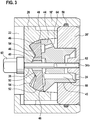
- Fig. 1 shows a tumble pump 10 having a housing 12 which is constructed of a plurality of housing parts, an end portion 14 has an inlet or inlet 16 of the tumble pump 10.
- a support member 16 which is inserted into the end part 14, carries a drive (electric motor) 18 for the tumble pump 10.
- a sealing member 20 provides a seal between a low-pressure region 24 and a high-pressure region 22 and a further end portion 26 serves as a pump stator 28th
- the housing parts 14, 16, 20 and 26 are held together by a metal ring 30.
- a shaft assembly 32 includes a drive shaft 34 which is journaled at one end in the support member 16 and at the other end in the pump stator 28 by means of plain bearings 36,38.
- the one-piece drive shaft 34 carries a rotor 40 of the electric motor 18, which is received in a stator 42 received on the support member 16.
- the drive shaft 34 carries a pump shaft 44 which is positively placed on the drive shaft 34.
- the pump shaft 44 is guided in the sealing part 20 such that a seal between the high-pressure region 22 and the low-pressure region 24 is achieved. Between the pump shaft 44 and the sealing part 20, a further sliding bearing 45 may be formed.
- the pump shaft 34 is an oblique (see Fig. 2 ) End surface 46 which cooperates with a pump rotor 48 and is mechanically coupled thereto.
- the pump rotor 48 and the pump stator 28 provide spherical surfaces 50, 52 which can slide on each other, wherein between the inner spherical surfaces 50 and the outer spherical surfaces 52 by a toothing between the pump rotor 48 and pump stator 28 chambers 54 (see Fig. 3 ) are formed, which increase and decrease upon rotation of the pump rotor 48 in the pump stator 28 and thus unfold a pumping action, so that a fluid from the low-pressure region 24 is conveyed into the high-pressure region 22.
- the pump rotor 48 has on its side facing away from the end face 46 a toothing which meshes with a toothing formed on the pump stator 28. Between the toothing of the pump rotor 48 and the toothing of the pump stator 28, the chambers 54 are formed.
- the toothing of the pump rotor 48 and the toothing of the pump stator 28 are designed, for example, as a cycloidal toothing, but may also be a different toothing.
- the pump rotor has a passage opening 49, through which the drive shaft 34 protrudes.
- the passage opening 49 has a larger diameter than the drive shaft 34 in this area, the drive shaft 34 may, as in the Fig. 1 shown in this area have a smaller diameter than in the region of the pump shaft 44th
- the drive shaft 34 can be acted upon by a spring 51 in the axial direction with force, so that via the (positively connected) pump shaft 44, the pump rotor 48 is pressed against the pump stator 28. This can be done alternatively or additionally by a corresponding offset of the rotor 40 of the electric motor 18 relative to the stator 42.
- the Fig. 2 shows a second embodiment of the tumble pump 10, wherein the components pump shaft 34, pump rotor 48 and pump stator 28 in comparison to the Fig. 1 are arranged vice versa. Furthermore, the drive shaft 34 has two shaft parts 34a and 34b. High pressure and low pressure areas are therefore also arranged in reverse.
- the housing 12 has a carrier part 16 ', which carries the drive 18 or the stator 42, the pump stator 28 and an end part 20', on which the pump stator 28 is seated.
- the opposite end part 14 with the inlet 16 is connected to the support part 16 'by means of an attachment 56.
- the end portion 20 ' has a further seal for the high-pressure region 24 with respect to the environment, which may be realized, for example, with a sealing ring 58 extending between the carrier part 16' and the end part 20 '.
- the drive shaft 34 comprises a first part 34 a, which carries the rotor 40 of the electric motor 18 and which is positively coupled via a pin 60 with a second part 34 b, which carries the pump rotor 48.
- the first part 34a is mounted in the housing 12 by means of a sliding bearing 36.
- the second part 34b is mounted in the stator 28 in a first sliding bearing 38 and in the end part 20 'in a second sliding bearing.
- the Fig. 3 shows a section of a tumble pump analogous to Fig. 2 , It can be seen that the pin 60 may be seated on the drive shaft part 34b on the stator 28 so that the drive shaft part 34b is fixed in an axial direction (away from the drive 18).
- the pump shaft has at least one channel 64 which communicates with the high-pressure region 22 and has at least one channel 66 which communicates with the low-pressure region 24.
- fluid from the low pressure region may flow into a pump chamber 54 via the channel 66, is transported by the rotor about the axis of the shaft, and then forced into the channel 64 by reducing the pumping chamber 54 as the pump rotor 48 is skewed.
Description
- Die Erfindung betrifft eine Taumelpumpe.
- Eine Ausführungsform einer Taumelpumpe ist aus der
WO 2008/110155 A1 bekannt. Dabei wird ein schräg auf einer Pumpenwelle der Taumelpumpe abgesetzter Pumpenrotor durch Rotation der Pumpenwelle gegenüber einem Pumpenstator in eine Taumelbewegung versetzt, so dass zwischen dem Pumpenrotor und dem Pumpenstator gebildete Pumpenkammern im Volumen vergrößert und verkleinert werden. Diese Kammern werden mit einem Eingang und einem Ausgang der Taumelpumpe verbunden, so dass ein Fluid durch die Taumelpumpe gefördert wird. - Auf die Pumpenwelle wirken radiale und axiale Kräfte, die beispielsweise, wie in der
WO 2008/110155 A1 gezeigt, durch ein Radialgleitlager für die Pumpenwelle aufgenommen werden. Der Gleitlagerspalt dient dabei auch zum Abdichten gegenüber dem komprimierten Fluid, was zu einem relativ langen Gleitlager führt. - Das Dokument
US 1 965 976 offenbart eine Pumpe mit einem Rotor, welcher um eine zur Antriebsachse senkrechten Achse oszilliert. Die Antriebsachse durchdringt den gesamten Pumpenmechanismus und ist an beiden Enden gelagert. - Das Dokument
WO 2005/024236 offenbart eine Drehkolbenpumpe mit einem Antriebsteil und einem Abtriebsteil, welche sich um unterschiedliche zueinander geeignete Achsen drehen. - Mit der Erfindung kann eine Taumelpumpe mit einer verkürzten Baulänge bereitgestellt werden. Weiter können mit der erfindungsgemäßen Taumelpumpe Reibungsverluste vermindert werden.
- Diese Vorteile können mit dem Gegenstand der unabhängigen Ansprüche erreicht werden. Weitere Ausführungsformen der Erfindung ergeben sich aus den abhängigen Ansprüchen und aus der folgenden Beschreibung.
- Die Erfindung betrifft eine Taumelpumpe zum Fördern von Fluid, beispielsweise Kraftstoff.
- Gemäß einer Ausführungsform der Erfindung umfasst die Taumelpumpe einen an einem Gehäuse der Taumelpumpe befestigten Pumpenstator und einen im Pumpenstator geführten Pumpenrotor. der von einer Antriebswelle mittels einer schrägen Stirnfläche derart angetrieben wird, dass er mit seiner Rotorachse um eine Antriebsachse der Antriebswelle taumelt. Die Antriebswelle durchragt dabei den Pumpenrotor durch eine Durchgangsöffnung und ist in einer Lagerung des Pumpenstators gelagert.
- Eine Rotation der Antriebswelle kann zu einem Taumeln des Pumpenrotors bezüglich des Pumpenstators führen, wodurch Pumpenkammern, die zwischen dem Pumpenstator und dem Pumpenrotor durch eine Verzahnung gebildet sind, derart vergrößert und verkleinert werden, dass ein Fluid durch die Taumelpumpe gefördert wird, wobei der Pumpenstator und der Pumpenrotor eine zykloidenförmige Verzahnung aufweisen.
- Bei der Taumelpumpe ist die Antriebswelle im Pumpenstator gelagert. Diese Lagerung kann in radialer und optional in radialer Richtung erfolgen. An einem weiteren Ende (dem Lager im Pumpenstator gegenüberliegend) ist die Antriebswelle in einem Gehäuseteil des Pumpengehäuses gelagert. Beide Lager, oder zumindest das Lager im Pumpenstator, können als Gleitlager ausgeführt sein. Damit können einerseits Radialkräfte von den beiden Lagern aufgenommen werden und anderseits kann die Dichtfunktion zwischen einer auf der Antriebswelle aufgesteckten Pumpenwelle und dem Pumpengehäuse von der Lagerung entkoppelt werden.
- Da die Antriebswelle an ihren Enden (und nicht in der Mitte) gelagert werden kann, kann ein Verkippen der Antriebswelle vermindert werden.
- Das Lager im Stator (und auch die anderen Lager) können mit einem geringeren Radius ausgeführt werden als der Radius der Pumpenwelle, der als Dichtstelle vorgesehen ist. Dies kann zu geringeren Gleitlagergeschwindigkeiten führen, was dem Entstehen von Wärme und Reibung entgegenwirken kann.
- Gemäß der Erfindung wird die schräge Stirnfläche von einer Pumpenwelle bereitstellt, die formschlüssig auf die Antriebswelle gesteckt ist. Eine formschlüssige Verbindung der Pumpenwelle direkt an der Antriebswelle kann einen Mitnehmer ersparen. Da es möglich ist, die Pumpenwelle berührungslos im Gehäuse laufen zu lassen, kann die Reibung reduziert werden. Die Anordnung kann auch resistenter gegenüber Partikeln sein, die an der Pumpenwelle vorbei durch eine Dichtstelle dringen können, da der Einsatz einer metallischen Hülse im Gehäuse möglich ist.
- Die Antriebswelle kann ein zusätzliches Gleitlager (beispielsweise an einem dem Pumpenstator gegenüberliegenden Ende) aufweisen. Dadurch können Radialkräfte eines Antriebsmotors von Radialkräften an der Pumpenwelle entkoppelt werden.
- Gemäß einer Ausführungsform der Erfindung trägt die Antriebswelle einen Rotor eines Elektromotors als Antrieb. Die Antriebswelle ist dann in einem Gehäuseteil der Taumelpumpe, das einen Stator des Elektromotors trägt, gelagert. Beispielsweise kann die Antriebswelle eine einstückige Welle sein, die an ihren beiden Enden im Stator und in einem Gehäuseteil gelagert ist.
- Gemäß einer Ausführungsform der Erfindung umfasst die Taumelpumpe weiter eine Feder zum Drücken der Antriebswelle in Richtung des Pumpenstators. Auf diese Weise kann die Dichtfunktion zwischen den Kugelflächen des Pumpenrotors bzw. Pumpenstators und der Verzahnung eingestellt bzw. erhöht werden, da der Pumpenrotor über die Antriebswelle und die Pumpenwelle in Richtung Pumpenstator gedrückt wird.
- Beispielsweise kann diese Axialkraft durch Kohle-Bürsten des Elektromotors (die eine Feder aufweisen) erzeugt werden.
- Gemäß einer Ausführungsform der Erfindung ist der Stator des Elektromotors derart gegenüber dem Rotor des Elektromotors in axialer Richtung versetzt, dass beim Betreiben des Motors die Antriebswelle durch elektromagnetische Kräfte in Richtung des Pumpenstators bewegt wird. Die Axialkraft kann auch direkt durch den Elektromotor erzeugt werden, so dass auf eine gesonderte Feder verzichtet werden kann.
- Gemäß einer Ausführungsform der Erfindung weist die Antriebswelle zwei miteinander gekoppelte Antriebswellenteile auf. Ein Teil der Antriebswelle (eine Motorwelle) kann den Rotor eines Elektromotors tragen. Ein weiterer, zweiter Teil der Antriebswelle kann die Pumpenwelle tragen. Beispielsweise kann der zweite Teil der Antriebswelle im Pumpenstator und in einem weiteren Gehäuseteil gelagert sein. Die beiden Teile der Antriebswelle können mittels eines Stifts formschlüssig gekoppelt sein. Bei einer zweiteiligen Antriebswelle können radiale Kräfte und Kipp-Momente besonders gut aufgenommen werden, da sie auf mehrere Lager für die Antriebswellenteile verteilt werden können.
- Gemäß der Erfindung weist die Durchgangsöffnung innen größeren Durchmesser auf als die Antriebswelle. Somit kann der Pumpenrotor um die Antriebswelle taumeln.
- Gemäß einer ersten Ausführungsform der Erfindung weist die schräge Stirnfläche von einem Antrieb der Taumelpumpe weg. Dabei ist die schräge Stirnfläche auf einer dem Elektromotor der Taumelpumpe abgewandten Seite der Pumpenwelle angeordnet. Bei dieser ersten Ausführung ist die Verzahnung des Pumpenstators dem Elektromotor zugewandt. Beispielsweise sind die Pumpenwelle und der Pumpenrotor (in dieser Reihenfolge) zwischen einem Antrieb der Pumpe und dem Pumpenstator aufgenommen. Dabei weisen die Kugelflächen des Pumpenrotors vom Antrieb weg.
- Gemäß einer zweiten Ausführungsform der Erfindung weist die schräge Stirnfläche zu einem Antrieb der Taumelpumpe hin. Dabei ist die schräge Stirnfläche auf einer dem Elektromotor der Taumelpumpe zugewandten Seite der Pumpenwelle angeordnet. Bei dieser zweiten Ausführung ist die Verzahnung des Pumpenstators auf der dem Elektromotor abgewandten Seite angeordnet. Beispielsweise sind der Pumpenstator, die Pumpenwelle und der Pumpenrotor (in dieser Reihenfolge) zwischen einem Antrieb und einem Gehäuseabschlussteil aufgenommen. In diesem Fall weisen die Kugelflächen des Pumpenrotors zum Antrieb hin.
- Ein Ende der Antriebswelle kann in dem Gehäuseabschlussteil gelagert sein. Weiter ist es möglich, dass ein Ende der Antriebswelle bzw. eines Antriebswellenteils in einem weiteren Gehäuseteil gelagert ist, das auch einen Antrieb der Taumelpumpe, wie etwa einen Elektromotor, aufnimmt.
- Im Folgenden werden Ausführungsbeispiele der Erfindung mit Bezug auf die beiliegenden Figuren detailliert beschrieben.
-
Fig. 1 zeigt einen Querschnitt durch eine Taumelpumpe gemäß einer Ausführungsform der Erfindung. -
Fig. 2 zeigt einen Querschnitt durch eine Taumelpumpe gemäß einer weiteren Ausführungsform der Erfindung. -
Fig. 3 zeigt einen Querschnitt eines Abschnitts einer Taumelpumpe gemäß einer weiteren Ausführungsform der Erfindung. - Grundsätzlich sind identische oder ähnliche Teile mit den gleichen Bezugszeichen versehen.
-
Fig. 1 zeigt eine Taumelpumpe 10, die ein Gehäuse 12 aufweist, das aus mehreren Gehäuseteilen aufgebaut ist, ein Endteil 14 weist einen Einlass bzw. Eingang 16 der Taumelpumpe 10 auf. Ein Trägerteil 16, das in das Endteil 14 gesteckt ist, trägt einen Antrieb (Elektromotor) 18 für die Taumelpumpe 10. Ein Dichtteil 20 stellt eine Abdichtung zwischen einem Niederdruckbereich 24 und einem Hochdruckbereich 22 bereit und ein weiteres Endteil 26 dient gleichzeitig als Pumpenstator 28. Die Gehäuseteile 14, 16, 20 und 26 werden von einem Blechring 30 zusammengehalten. - Eine Wellenanordnung 32 umfasst eine Antriebswelle 34, die an einem Ende in dem Trägerteil 16 und am anderen Ende im Pumpenstator 28 mittels Gleitlagern 36, 38 gelagert ist. Die einstückige Antriebswelle 34 trägt einen Rotor 40 des Elektromotors 18, der in einem am Trägerteil 16 aufgenommen Stator 42 aufgenommen ist. Weiter trägt die Antriebswelle 34 eine Pumpenwelle 44, die formschlüssig auf die Antriebswelle 34 gesteckt ist. Die Pumpenwelle 44 ist im Dichtteil 20 derart geführt, dass eine Abdichtung zwischen dem Hochdruckbereich 22 und dem Niederdruckbereich 24 erreicht wird. Zwischen der Pumpenwelle 44 und dem Dichtteil 20 kann ein weiteres Gleitlager 45 gebildet sein.
- Die Pumpenwelle 34 stellt eine schräge (siehe dazu
Fig. 2 ) Stirnfläche 46 bereit, die mit einem Pumpenrotor 48 zusammenwirkt und mit diesem mechanisch gekoppelt ist. Der Pumpenrotor 48 und der Pumpenstator 28 stellen Kugelflächen 50, 52 bereit, die aufeinander gleiten können, wobei zwischen den inneren Kugelflächen 50 und den äußeren Kugelflächen 52 durch eine Verzahnung zwischen Pumpenrotor 48 und Pumpenstator 28 Kammern 54 (sieheFig. 3 ) gebildet sind, die sich bei Drehung des Pumpenrotors 48 im Pumpenstator 28 vergrößern und verkleinern und somit eine Pumpwirkung entfalten, so dass ein Fluid aus dem Niederdruckbereich 24 in den Hochdruckbereich 22 gefördert wird. - Der Pumpenrotor 48 weist an seiner der Stirnfläche 46 abgewandten Seite eine Verzahnung auf, die auf einer auf dem Pumpenstator 28 ausgebildeten Verzahnung kämmt. Zwischen der Verzahnung des Pumpenrotors 48 und der Verzahnung des Pumpenstators 28 sind die Kammern 54 gebildet. Die Verzahnung des Pumpenrotors 48 und die Verzahnung des Pumpenstators 28 sind beispielsweise als Zykloidenverzahnung ausgeführt, können aber auch eine andere Verzahnung sein.
- Der Pumpenrotor weist eine Durchgangsöffnung 49 auf, durch die die Antriebswelle 34 ragt. Die Durchgangsöffnung 49 weist einen größeren Durchmesser als die Antriebswelle 34 in diesem Bereich auf, Die Antriebswelle 34 kann, wie in der
Fig. 1 gezeigt, in diesem Bereich einen geringeren Durchmesser aufweisen, als im Bereich der Pumpenwelle 44. - Die Antriebswelle 34 kann von einer Feder 51 in axialer Richtung mit Kraft beaufschlagt werden, so dass über die (formschlüssig verbundene) Pumpenwelle 44 der Pumpenrotor 48 gegen den Pumpenstator 28 gedrückt wird. Dies kann alternativ oder zusätzlich durch einen entsprechenden Versatz des Rotors 40 des Elektromotors 18 gegenüber dem Stator 42 erfolgen.
- Die
Fig. 2 zeigt ein zweites Ausführungsbeispiel der Taumelpumpe 10, bei der die Komponenten Pumpenwelle 34, Pumpenrotor 48 und Pumpenstator 28 im Vergleich zu derFig. 1 umgekehrt angeordnet sind. Weiter weist die Antriebswelle 34 zwei Wellenteile 34a und 34b auf. Hochdruck- und Niederdruckbereich sind daher ebenfalls umgekehrt angeordnet. - Das Gehäuse 12 weist ein Trägerteil 16' auf, das den Antrieb 18 bzw. den Stator 42, den Pumpenstator 28 und ein Endteil 20' trägt, auf dem der Pumpenstator 28 aufsitzt. Das gegenüberliegende Endteil 14 mit dem Einlass 16 ist mit dem Trägerteil 16' mittels eines Aufsatzes 56 verbunden.
- Das Endteil 20' weist eine weitere Dichtung für den Hochdruckbereich 24 gegenüber der Umgebung auf, die beispielsweise mit einem zwischen dem Trägerteil 16' und dem Endteil 20' verlaufenden Dichtring 58 realisiert sein kann.
- Die Antriebswelle 34 umfasst einen ersten Teil 34a, der den Rotor 40 des Elektromotors 18 trägt und der mit einem zweiten Teil 34b, der den Pumpenrotor 48 trägt, über einen Stift 60 formschlüssig gekoppelt ist. Der erste Teil 34a ist mittels eines Gleitlagers 36 im Gehäuse 12 gelagert. Der zweite Teil 34b ist im Stator 28 in einem ersten Gleitlager 38 und im Endteil 20' in einem zweiten Gleitlager gelagert.
- Die
Fig. 3 zeigt einen Ausschnitt aus einer Taumelpumpe analog derFig. 2 . Es ist zu erkennen, dass der Stift 60 an dem Antriebswellenteil 34b auf dem Stator 28 abgesetzt sein kann, so dass der Antriebswellenteil 34b in einer axialen Richtung (vom Antrieb 18 weg) fixiert ist. - In der
Fig. 3 ist auch gezeigt, dass die Pumpenwelle zumindest einen Kanal 64 aufweist, der mit dem Hochdruckbereich 22 in Verbindung steht und zumindest einen Kanal 66 aufweist, der mit dem Niederdruckbereich 24 in Verbindung steht. - Bei Drehung des Rotors 48 kann Fluid aus dem Niederdruckbereich über den Kanal 66 in eine Pumpenkammer 54 strömen, wird vom Rotor um die Achse der Welle transportiert und dann durch Verkleinerung der Pumpenkammer 54, da der Pumpenrotor 48 schräg steht, in den Kanal 64 gepresst.
Claims (7)
- Taumelpumpe (10), umfassend:einen an einem Gehäuse (12) der Taumelpumpe befestigten Pumpenstator (28); einen im Pumpenstator (28) geführten Pumpenrotor (48), der von einer einen Rotor eines Elektromotors tragenden Antriebswelle (34) mittels einer schrägen Stirnfläche (46) derart angetrieben wird, dass er mit seiner Rotorachse um eine Antriebsachse der Antriebswelle (34) taumelt; wobei der Pumpenstator und der Pumpenrotor (48) eine zykloidenförmige Verzahnung aufweisen, wobei die schräge Stirnfläche (46) von einer Pumpenwelle (44) bereitgestellt und auf einer dem Elektromotor (18) der Taumelpumpe zugewandten oder abgewandten Seite der Pumpenwelle (44) angeordnet ist, dadurch gekennzeichnet, dassdie Pumpenwelle (44) einen Durchgang aufweist unddie Antriebswelle (34) in den Durchgang der Pumpenwelle (44) formschlüssig eingesteckt ist und den Pumpenrotor (48) durch eine Durchgangsöffnung (49) durchragt und in einer Lagerung (38) des Pumpenstators (28) gelagert ist, dass die Durchgangsöffnung (49) des Pumpenrotors (48) einen größeren Durchmesser aufweist als die Antriebswelle (34) und dass die Antriebswelle (34) an einem dem Pumpenstator (28) gegenüberliegenden Ende in einem Gehäuseteil (16,16') des Gehäuses (12) gelagert ist.
- Taumelpumpe (10) nach Anspruch 1,
wobei eine Antriebswelle (34) einen Rotor (40) eines Elektromotors (18) trägt und die Antriebswelle (34) in einem Gehäuseteil (16, 16') der Taumelpumpe, das einen Stator (42) des Elektromotors (18) trägt, gelagert ist. - Taumelpumpe (10) nach einem der vorhergehenden Ansprüche, weiter umfassend:
eine Feder (51) zum Drücken der Antriebswelle (34) in Richtung des Pumpenstators (28). - Taumelpumpe (10) nach Anspruch 2 oder 3,
wobei der Stator (42) des Elektromotors (18) derart gegenüber dem Rotor (40) des Elektromotors (18) in axialer Richtung versetzt ist, dass beim Betreiben des Elektromotors die Antriebswelle (34) durch elektromagnetische Kräfte in Richtung des Pumpenstators (28) bewegt wird. - Taumelpumpe (10) nach einem der vorhergehenden Ansprüche,
wobei die Antriebswelle (34) zwei miteinander gekoppelte Antriebswellenteile (34a, 34b) aufweist. - Taumelpumpe (10) nach einem der vorhergehenden Ansprüche,
wobei der Pumpenstator (28), die Pumpenwelle (44) und der Pumpenrotor (48) in Richtung der Antriebswelle gesehen zwischen dem Elektromotor (18) und einem Gehäuseabschlussteil (20') aufgenommen sind; und wobei die Antriebswelle (34) in dem Gehäuseabschlussteil (20') gelagert ist. - Taumelpumpe (10) nach einem der vorhergehenden Ansprüche,
wobei der Pumpenstator (28) ein Gleitlager (38) für die Antriebswelle (34) aufweist.
Applications Claiming Priority (2)
| Application Number | Priority Date | Filing Date | Title |
|---|---|---|---|
| DE102013226974.9A DE102013226974A1 (de) | 2013-12-20 | 2013-12-20 | Taumelpumpe mit im Stator gelagerter Welle |
| PCT/EP2014/074158 WO2015090730A1 (de) | 2013-12-20 | 2014-11-10 | Taumelpumpe mit im stator gelagerter welle |
Publications (2)
| Publication Number | Publication Date |
|---|---|
| EP3084126A1 EP3084126A1 (de) | 2016-10-26 |
| EP3084126B1 true EP3084126B1 (de) | 2019-02-27 |
Family
ID=51903887
Family Applications (1)
| Application Number | Title | Priority Date | Filing Date |
|---|---|---|---|
| EP14799383.6A Active EP3084126B1 (de) | 2013-12-20 | 2014-11-10 | Taumelpumpe mit im stator gelagerter welle |
Country Status (3)
| Country | Link |
|---|---|
| EP (1) | EP3084126B1 (de) |
| DE (1) | DE102013226974A1 (de) |
| WO (1) | WO2015090730A1 (de) |
Cited By (1)
| Publication number | Priority date | Publication date | Assignee | Title |
|---|---|---|---|---|
| DE102021115440A1 (de) | 2021-06-15 | 2022-12-15 | Schwäbische Hüttenwerke Automotive GmbH | Rotationspumpe mit einer Axialschubbegrenzungseinrichtung |
Families Citing this family (2)
| Publication number | Priority date | Publication date | Assignee | Title |
|---|---|---|---|---|
| DE102020124825A1 (de) | 2020-09-23 | 2022-03-24 | Kolektor Group D.O.O. | Motor-Pumpe-Einheit |
| DE102021103306A1 (de) | 2021-02-12 | 2022-08-18 | Kolektor Group D.O.O. | Handgeführtes Druckflüssigkeitsgerät |
Citations (1)
| Publication number | Priority date | Publication date | Assignee | Title |
|---|---|---|---|---|
| WO2005024236A1 (de) * | 2003-09-11 | 2005-03-17 | Cor Pumps + Compressors Ag | Drehkolbenmaschine |
Family Cites Families (7)
| Publication number | Priority date | Publication date | Assignee | Title |
|---|---|---|---|---|
| US1965976A (en) * | 1932-04-16 | 1934-07-10 | James L Kempthorne | Mechanism for pumps, compressors, and the like |
| US2380886A (en) * | 1941-12-18 | 1945-07-31 | Hydraulic Dev Corp Inc | Balanced ball type vane pump or motor |
| FR1104109A (fr) * | 1954-04-28 | 1955-11-16 | Rech S Etudes | Perfectionnement apporté à des pompes ou moteurs à fluide à pistons |
| AT322362B (de) * | 1973-03-12 | 1975-05-26 | Keplinger Klaus | Motor und/oder pumpe |
| JP2001200784A (ja) * | 2000-01-19 | 2001-07-27 | Toyota Autom Loom Works Ltd | 斜板式圧縮機 |
| JP5135361B2 (ja) | 2007-03-13 | 2013-02-06 | ローベルト ボツシユ ゲゼルシヤフト ミツト ベシユレンクテル ハフツング | ポンプ若しくはモータ |
| DE102011080803A1 (de) * | 2011-08-11 | 2013-02-14 | Robert Bosch Gmbh | Drehkolbenmaschine, die als Pumpe, Verdichter oder Motor arbeitet |
-
2013
- 2013-12-20 DE DE102013226974.9A patent/DE102013226974A1/de not_active Withdrawn
-
2014
- 2014-11-10 EP EP14799383.6A patent/EP3084126B1/de active Active
- 2014-11-10 WO PCT/EP2014/074158 patent/WO2015090730A1/de active Application Filing
Patent Citations (1)
| Publication number | Priority date | Publication date | Assignee | Title |
|---|---|---|---|---|
| WO2005024236A1 (de) * | 2003-09-11 | 2005-03-17 | Cor Pumps + Compressors Ag | Drehkolbenmaschine |
Cited By (1)
| Publication number | Priority date | Publication date | Assignee | Title |
|---|---|---|---|---|
| DE102021115440A1 (de) | 2021-06-15 | 2022-12-15 | Schwäbische Hüttenwerke Automotive GmbH | Rotationspumpe mit einer Axialschubbegrenzungseinrichtung |
Also Published As
| Publication number | Publication date |
|---|---|
| EP3084126A1 (de) | 2016-10-26 |
| WO2015090730A1 (de) | 2015-06-25 |
| DE102013226974A1 (de) | 2015-06-25 |
Similar Documents
| Publication | Publication Date | Title |
|---|---|---|
| EP1723335A1 (de) | Axialkolbenmaschine | |
| EP1797320A1 (de) | RADIALKOLBENPUMPE MIT ROLLENSTÖßEL | |
| WO2014187518A1 (de) | Gelenkanordnungen | |
| EP2359005B1 (de) | Flügelzellenpumpe | |
| EP3084126B1 (de) | Taumelpumpe mit im stator gelagerter welle | |
| EP2450571A1 (de) | Schleifringeinheit und Verwendung der Schleifringeinheit in einer Windkraftanlage | |
| WO2012034619A1 (de) | Axialkolbenmaschine | |
| EP0949419B1 (de) | Innenzahnradmaschine | |
| EP0666422B1 (de) | Lagerung und Antrieb der Rotoren eines Schraubenrotorverdichters | |
| WO2011161178A1 (de) | Axialkolbenmaschine | |
| DE102009055945A1 (de) | Flügelzellenpumpe | |
| EP2662570B1 (de) | Vakuumpumpe | |
| WO2005024237A1 (de) | Drehkolbenmaschine | |
| DE102019118708A1 (de) | Druckversorgungseinrichtung mit einer Zahnradpumpe | |
| DE19650274A1 (de) | Pumpenaggregat | |
| DE102005025869B4 (de) | Geräuscharme Kolbenpumpe | |
| EP3500732B1 (de) | Förderaggregat | |
| EP2035265B1 (de) | Fahrzeugbremsanlagen-kolbenpumpe | |
| EP2655802B1 (de) | Zahnradmaschine mit kleinem durchmesser-längenverhältnis | |
| DE3610302A1 (de) | Maschine mit fluiddurchsatz der spiralbauart | |
| DE102016103902B4 (de) | Rotoranordnung für eine Pumpe sowie Pumpenaggregat | |
| DE202019107191U1 (de) | Druckversorgungseinrichtung mit einer Zahnradpumpe | |
| DE102019118697A1 (de) | Zahnradpumpe | |
| DE102019202336A1 (de) | Exzenterantrieb einer Exzenterpumpe | |
| WO2024061583A1 (de) | Folienlager und lagerbock zum aufnehmen eines folienlagers |
Legal Events
| Date | Code | Title | Description |
|---|---|---|---|
| PUAI | Public reference made under article 153(3) epc to a published international application that has entered the european phase |
Free format text: ORIGINAL CODE: 0009012 |
|
| 17P | Request for examination filed |
Effective date: 20160720 |
|
| AK | Designated contracting states |
Kind code of ref document: A1 Designated state(s): AL AT BE BG CH CY CZ DE DK EE ES FI FR GB GR HR HU IE IS IT LI LT LU LV MC MK MT NL NO PL PT RO RS SE SI SK SM TR |
|
| AX | Request for extension of the european patent |
Extension state: BA ME |
|
| DAX | Request for extension of the european patent (deleted) | ||
| STAA | Information on the status of an ep patent application or granted ep patent |
Free format text: STATUS: EXAMINATION IS IN PROGRESS |
|
| 17Q | First examination report despatched |
Effective date: 20171127 |
|
| GRAP | Despatch of communication of intention to grant a patent |
Free format text: ORIGINAL CODE: EPIDOSNIGR1 |
|
| STAA | Information on the status of an ep patent application or granted ep patent |
Free format text: STATUS: GRANT OF PATENT IS INTENDED |
|
| INTG | Intention to grant announced |
Effective date: 20181126 |
|
| GRAS | Grant fee paid |
Free format text: ORIGINAL CODE: EPIDOSNIGR3 |
|
| GRAA | (expected) grant |
Free format text: ORIGINAL CODE: 0009210 |
|
| STAA | Information on the status of an ep patent application or granted ep patent |
Free format text: STATUS: THE PATENT HAS BEEN GRANTED |
|
| AK | Designated contracting states |
Kind code of ref document: B1 Designated state(s): AL AT BE BG CH CY CZ DE DK EE ES FI FR GB GR HR HU IE IS IT LI LT LU LV MC MK MT NL NO PL PT RO RS SE SI SK SM TR |
|
| REG | Reference to a national code |
Ref country code: GB Ref legal event code: FG4D Free format text: NOT ENGLISH |
|
| REG | Reference to a national code |
Ref country code: CH Ref legal event code: EP |
|
| REG | Reference to a national code |
Ref country code: DE Ref legal event code: R096 Ref document number: 502014010973 Country of ref document: DE |
|
| REG | Reference to a national code |
Ref country code: AT Ref legal event code: REF Ref document number: 1101624 Country of ref document: AT Kind code of ref document: T Effective date: 20190315 |
|
| REG | Reference to a national code |
Ref country code: IE Ref legal event code: FG4D Free format text: LANGUAGE OF EP DOCUMENT: GERMAN |
|
| REG | Reference to a national code |
Ref country code: NL Ref legal event code: MP Effective date: 20190227 |
|
| REG | Reference to a national code |
Ref country code: LT Ref legal event code: MG4D |
|
| PG25 | Lapsed in a contracting state [announced via postgrant information from national office to epo] |
Ref country code: NO Free format text: LAPSE BECAUSE OF FAILURE TO SUBMIT A TRANSLATION OF THE DESCRIPTION OR TO PAY THE FEE WITHIN THE PRESCRIBED TIME-LIMIT Effective date: 20190527 Ref country code: PT Free format text: LAPSE BECAUSE OF FAILURE TO SUBMIT A TRANSLATION OF THE DESCRIPTION OR TO PAY THE FEE WITHIN THE PRESCRIBED TIME-LIMIT Effective date: 20190627 Ref country code: LT Free format text: LAPSE BECAUSE OF FAILURE TO SUBMIT A TRANSLATION OF THE DESCRIPTION OR TO PAY THE FEE WITHIN THE PRESCRIBED TIME-LIMIT Effective date: 20190227 Ref country code: SE Free format text: LAPSE BECAUSE OF FAILURE TO SUBMIT A TRANSLATION OF THE DESCRIPTION OR TO PAY THE FEE WITHIN THE PRESCRIBED TIME-LIMIT Effective date: 20190227 Ref country code: NL Free format text: LAPSE BECAUSE OF FAILURE TO SUBMIT A TRANSLATION OF THE DESCRIPTION OR TO PAY THE FEE WITHIN THE PRESCRIBED TIME-LIMIT Effective date: 20190227 Ref country code: FI Free format text: LAPSE BECAUSE OF FAILURE TO SUBMIT A TRANSLATION OF THE DESCRIPTION OR TO PAY THE FEE WITHIN THE PRESCRIBED TIME-LIMIT Effective date: 20190227 |
|
| PG25 | Lapsed in a contracting state [announced via postgrant information from national office to epo] |
Ref country code: RS Free format text: LAPSE BECAUSE OF FAILURE TO SUBMIT A TRANSLATION OF THE DESCRIPTION OR TO PAY THE FEE WITHIN THE PRESCRIBED TIME-LIMIT Effective date: 20190227 Ref country code: BG Free format text: LAPSE BECAUSE OF FAILURE TO SUBMIT A TRANSLATION OF THE DESCRIPTION OR TO PAY THE FEE WITHIN THE PRESCRIBED TIME-LIMIT Effective date: 20190527 Ref country code: IS Free format text: LAPSE BECAUSE OF FAILURE TO SUBMIT A TRANSLATION OF THE DESCRIPTION OR TO PAY THE FEE WITHIN THE PRESCRIBED TIME-LIMIT Effective date: 20190627 Ref country code: LV Free format text: LAPSE BECAUSE OF FAILURE TO SUBMIT A TRANSLATION OF THE DESCRIPTION OR TO PAY THE FEE WITHIN THE PRESCRIBED TIME-LIMIT Effective date: 20190227 Ref country code: GR Free format text: LAPSE BECAUSE OF FAILURE TO SUBMIT A TRANSLATION OF THE DESCRIPTION OR TO PAY THE FEE WITHIN THE PRESCRIBED TIME-LIMIT Effective date: 20190528 Ref country code: HR Free format text: LAPSE BECAUSE OF FAILURE TO SUBMIT A TRANSLATION OF THE DESCRIPTION OR TO PAY THE FEE WITHIN THE PRESCRIBED TIME-LIMIT Effective date: 20190227 |
|
| PG25 | Lapsed in a contracting state [announced via postgrant information from national office to epo] |
Ref country code: EE Free format text: LAPSE BECAUSE OF FAILURE TO SUBMIT A TRANSLATION OF THE DESCRIPTION OR TO PAY THE FEE WITHIN THE PRESCRIBED TIME-LIMIT Effective date: 20190227 Ref country code: DK Free format text: LAPSE BECAUSE OF FAILURE TO SUBMIT A TRANSLATION OF THE DESCRIPTION OR TO PAY THE FEE WITHIN THE PRESCRIBED TIME-LIMIT Effective date: 20190227 Ref country code: SK Free format text: LAPSE BECAUSE OF FAILURE TO SUBMIT A TRANSLATION OF THE DESCRIPTION OR TO PAY THE FEE WITHIN THE PRESCRIBED TIME-LIMIT Effective date: 20190227 Ref country code: AL Free format text: LAPSE BECAUSE OF FAILURE TO SUBMIT A TRANSLATION OF THE DESCRIPTION OR TO PAY THE FEE WITHIN THE PRESCRIBED TIME-LIMIT Effective date: 20190227 Ref country code: ES Free format text: LAPSE BECAUSE OF FAILURE TO SUBMIT A TRANSLATION OF THE DESCRIPTION OR TO PAY THE FEE WITHIN THE PRESCRIBED TIME-LIMIT Effective date: 20190227 Ref country code: RO Free format text: LAPSE BECAUSE OF FAILURE TO SUBMIT A TRANSLATION OF THE DESCRIPTION OR TO PAY THE FEE WITHIN THE PRESCRIBED TIME-LIMIT Effective date: 20190227 Ref country code: CZ Free format text: LAPSE BECAUSE OF FAILURE TO SUBMIT A TRANSLATION OF THE DESCRIPTION OR TO PAY THE FEE WITHIN THE PRESCRIBED TIME-LIMIT Effective date: 20190227 |
|
| REG | Reference to a national code |
Ref country code: DE Ref legal event code: R097 Ref document number: 502014010973 Country of ref document: DE |
|
| PG25 | Lapsed in a contracting state [announced via postgrant information from national office to epo] |
Ref country code: SM Free format text: LAPSE BECAUSE OF FAILURE TO SUBMIT A TRANSLATION OF THE DESCRIPTION OR TO PAY THE FEE WITHIN THE PRESCRIBED TIME-LIMIT Effective date: 20190227 Ref country code: PL Free format text: LAPSE BECAUSE OF FAILURE TO SUBMIT A TRANSLATION OF THE DESCRIPTION OR TO PAY THE FEE WITHIN THE PRESCRIBED TIME-LIMIT Effective date: 20190227 |
|
| PLBE | No opposition filed within time limit |
Free format text: ORIGINAL CODE: 0009261 |
|
| STAA | Information on the status of an ep patent application or granted ep patent |
Free format text: STATUS: NO OPPOSITION FILED WITHIN TIME LIMIT |
|
| 26N | No opposition filed |
Effective date: 20191128 |
|
| PG25 | Lapsed in a contracting state [announced via postgrant information from national office to epo] |
Ref country code: SI Free format text: LAPSE BECAUSE OF FAILURE TO SUBMIT A TRANSLATION OF THE DESCRIPTION OR TO PAY THE FEE WITHIN THE PRESCRIBED TIME-LIMIT Effective date: 20190227 |
|
| PGFP | Annual fee paid to national office [announced via postgrant information from national office to epo] |
Ref country code: IT Payment date: 20191120 Year of fee payment: 6 |
|
| PG25 | Lapsed in a contracting state [announced via postgrant information from national office to epo] |
Ref country code: TR Free format text: LAPSE BECAUSE OF FAILURE TO SUBMIT A TRANSLATION OF THE DESCRIPTION OR TO PAY THE FEE WITHIN THE PRESCRIBED TIME-LIMIT Effective date: 20190227 |
|
| REG | Reference to a national code |
Ref country code: CH Ref legal event code: PL |
|
| PG25 | Lapsed in a contracting state [announced via postgrant information from national office to epo] |
Ref country code: MC Free format text: LAPSE BECAUSE OF FAILURE TO SUBMIT A TRANSLATION OF THE DESCRIPTION OR TO PAY THE FEE WITHIN THE PRESCRIBED TIME-LIMIT Effective date: 20190227 Ref country code: LI Free format text: LAPSE BECAUSE OF NON-PAYMENT OF DUE FEES Effective date: 20191130 Ref country code: LU Free format text: LAPSE BECAUSE OF NON-PAYMENT OF DUE FEES Effective date: 20191110 Ref country code: CH Free format text: LAPSE BECAUSE OF NON-PAYMENT OF DUE FEES Effective date: 20191130 |
|
| REG | Reference to a national code |
Ref country code: BE Ref legal event code: MM Effective date: 20191130 |
|
| PG25 | Lapsed in a contracting state [announced via postgrant information from national office to epo] |
Ref country code: IE Free format text: LAPSE BECAUSE OF NON-PAYMENT OF DUE FEES Effective date: 20191110 |
|
| PG25 | Lapsed in a contracting state [announced via postgrant information from national office to epo] |
Ref country code: BE Free format text: LAPSE BECAUSE OF NON-PAYMENT OF DUE FEES Effective date: 20191130 |
|
| REG | Reference to a national code |
Ref country code: AT Ref legal event code: MM01 Ref document number: 1101624 Country of ref document: AT Kind code of ref document: T Effective date: 20191110 |
|
| PG25 | Lapsed in a contracting state [announced via postgrant information from national office to epo] |
Ref country code: AT Free format text: LAPSE BECAUSE OF NON-PAYMENT OF DUE FEES Effective date: 20191110 |
|
| PG25 | Lapsed in a contracting state [announced via postgrant information from national office to epo] |
Ref country code: CY Free format text: LAPSE BECAUSE OF FAILURE TO SUBMIT A TRANSLATION OF THE DESCRIPTION OR TO PAY THE FEE WITHIN THE PRESCRIBED TIME-LIMIT Effective date: 20190227 |
|
| PG25 | Lapsed in a contracting state [announced via postgrant information from national office to epo] |
Ref country code: HU Free format text: LAPSE BECAUSE OF FAILURE TO SUBMIT A TRANSLATION OF THE DESCRIPTION OR TO PAY THE FEE WITHIN THE PRESCRIBED TIME-LIMIT; INVALID AB INITIO Effective date: 20141110 Ref country code: MT Free format text: LAPSE BECAUSE OF FAILURE TO SUBMIT A TRANSLATION OF THE DESCRIPTION OR TO PAY THE FEE WITHIN THE PRESCRIBED TIME-LIMIT Effective date: 20190227 |
|
| PG25 | Lapsed in a contracting state [announced via postgrant information from national office to epo] |
Ref country code: IT Free format text: LAPSE BECAUSE OF NON-PAYMENT OF DUE FEES Effective date: 20201110 |
|
| PG25 | Lapsed in a contracting state [announced via postgrant information from national office to epo] |
Ref country code: MK Free format text: LAPSE BECAUSE OF FAILURE TO SUBMIT A TRANSLATION OF THE DESCRIPTION OR TO PAY THE FEE WITHIN THE PRESCRIBED TIME-LIMIT Effective date: 20190227 |
|
| PGFP | Annual fee paid to national office [announced via postgrant information from national office to epo] |
Ref country code: DE Payment date: 20230124 Year of fee payment: 9 |
|
| PGFP | Annual fee paid to national office [announced via postgrant information from national office to epo] |
Ref country code: GB Payment date: 20231123 Year of fee payment: 10 |
|
| PGFP | Annual fee paid to national office [announced via postgrant information from national office to epo] |
Ref country code: FR Payment date: 20231123 Year of fee payment: 10 |
|
| PGFP | Annual fee paid to national office [announced via postgrant information from national office to epo] |
Ref country code: DE Payment date: 20240123 Year of fee payment: 10 |