EP3083394B1 - Herstellverfahren zum herstellen eines tragenden rumpfpaneels sowie damit herstellbares rumpfpaneel - Google Patents
Herstellverfahren zum herstellen eines tragenden rumpfpaneels sowie damit herstellbares rumpfpaneel Download PDFInfo
- Publication number
- EP3083394B1 EP3083394B1 EP14828127.2A EP14828127A EP3083394B1 EP 3083394 B1 EP3083394 B1 EP 3083394B1 EP 14828127 A EP14828127 A EP 14828127A EP 3083394 B1 EP3083394 B1 EP 3083394B1
- Authority
- EP
- European Patent Office
- Prior art keywords
- panel
- filler
- filler panel
- fuselage
- shell
- Prior art date
- Legal status (The legal status is an assumption and is not a legal conclusion. Google has not performed a legal analysis and makes no representation as to the accuracy of the status listed.)
- Active
Links
Images
Classifications
-
- B—PERFORMING OPERATIONS; TRANSPORTING
- B64—AIRCRAFT; AVIATION; COSMONAUTICS
- B64C—AEROPLANES; HELICOPTERS
- B64C1/00—Fuselages; Constructional features common to fuselages, wings, stabilising surfaces or the like
- B64C1/06—Frames; Stringers; Longerons ; Fuselage sections
- B64C1/12—Construction or attachment of skin panels
-
- B—PERFORMING OPERATIONS; TRANSPORTING
- B64—AIRCRAFT; AVIATION; COSMONAUTICS
- B64C—AEROPLANES; HELICOPTERS
- B64C1/00—Fuselages; Constructional features common to fuselages, wings, stabilising surfaces or the like
- B64C1/06—Frames; Stringers; Longerons ; Fuselage sections
- B64C1/066—Interior liners
-
- B—PERFORMING OPERATIONS; TRANSPORTING
- B64—AIRCRAFT; AVIATION; COSMONAUTICS
- B64C—AEROPLANES; HELICOPTERS
- B64C1/00—Fuselages; Constructional features common to fuselages, wings, stabilising surfaces or the like
- B64C1/06—Frames; Stringers; Longerons ; Fuselage sections
- B64C1/068—Fuselage sections
-
- B—PERFORMING OPERATIONS; TRANSPORTING
- B64—AIRCRAFT; AVIATION; COSMONAUTICS
- B64F—GROUND OR AIRCRAFT-CARRIER-DECK INSTALLATIONS SPECIALLY ADAPTED FOR USE IN CONNECTION WITH AIRCRAFT; DESIGNING, MANUFACTURING, ASSEMBLING, CLEANING, MAINTAINING OR REPAIRING AIRCRAFT, NOT OTHERWISE PROVIDED FOR; HANDLING, TRANSPORTING, TESTING OR INSPECTING AIRCRAFT COMPONENTS, NOT OTHERWISE PROVIDED FOR
- B64F5/00—Designing, manufacturing, assembling, cleaning, maintaining or repairing aircraft, not otherwise provided for; Handling, transporting, testing or inspecting aircraft components, not otherwise provided for
- B64F5/10—Manufacturing or assembling aircraft, e.g. jigs therefor
-
- B—PERFORMING OPERATIONS; TRANSPORTING
- B64—AIRCRAFT; AVIATION; COSMONAUTICS
- B64C—AEROPLANES; HELICOPTERS
- B64C1/00—Fuselages; Constructional features common to fuselages, wings, stabilising surfaces or the like
- B64C2001/0054—Fuselage structures substantially made from particular materials
- B64C2001/0072—Fuselage structures substantially made from particular materials from composite materials
-
- Y—GENERAL TAGGING OF NEW TECHNOLOGICAL DEVELOPMENTS; GENERAL TAGGING OF CROSS-SECTIONAL TECHNOLOGIES SPANNING OVER SEVERAL SECTIONS OF THE IPC; TECHNICAL SUBJECTS COVERED BY FORMER USPC CROSS-REFERENCE ART COLLECTIONS [XRACs] AND DIGESTS
- Y02—TECHNOLOGIES OR APPLICATIONS FOR MITIGATION OR ADAPTATION AGAINST CLIMATE CHANGE
- Y02P—CLIMATE CHANGE MITIGATION TECHNOLOGIES IN THE PRODUCTION OR PROCESSING OF GOODS
- Y02P70/00—Climate change mitigation technologies in the production process for final industrial or consumer products
- Y02P70/50—Manufacturing or production processes characterised by the final manufactured product
-
- Y—GENERAL TAGGING OF NEW TECHNOLOGICAL DEVELOPMENTS; GENERAL TAGGING OF CROSS-SECTIONAL TECHNOLOGIES SPANNING OVER SEVERAL SECTIONS OF THE IPC; TECHNICAL SUBJECTS COVERED BY FORMER USPC CROSS-REFERENCE ART COLLECTIONS [XRACs] AND DIGESTS
- Y02—TECHNOLOGIES OR APPLICATIONS FOR MITIGATION OR ADAPTATION AGAINST CLIMATE CHANGE
- Y02T—CLIMATE CHANGE MITIGATION TECHNOLOGIES RELATED TO TRANSPORTATION
- Y02T50/00—Aeronautics or air transport
- Y02T50/40—Weight reduction
Definitions
- the invention relates to a production method for producing a load-bearing fuselage panel for a fuselage section of an aircraft fuselage in the area of an aircraft cabin.
- WO 2012 / 152 934 A2 discloses a panel for detachable arrangement between an outer skin of a means of transport and an inner lining of the means of transport, with a plate-like insulating body, the at least one integrated Has an air conditioning duct and has at least one groove-like line guide that is open in sections towards the inner surface, a method for producing such a panel and an aircraft with a multiplicity of such panels.
- a fuselage structural component for an aircraft which has a load-bearing inner skin, a non-load-bearing outer skin and a sandwich core in between.
- a foam layer is proposed as the sandwich core.
- the inner skin has frames and stringers on the inside and stringers on the outside.
- U.S. 5,985,362 A discloses an insulation system for aircraft fuselage walls.
- the insulation is formed by a sprayed foam sprayed against a barrier material and against the inside of the skin over any inwardly projecting structural members.
- a fuselage segment for an aircraft and a method for producing the fuselage segment is known.
- the fuselage segment is provided with an outer skin and an inner skin spaced apart by a core.
- Line channels for system integration are integrated into the core.
- the object of the invention is to simplify the manufacture of an aircraft fuselage and the maintenance of aircraft.
- the invention proposes a manufacturing method for manufacturing a load-bearing fuselage panel according to claim 1.
- the invention provides a manufacturing method for manufacturing a load-bearing fuselage panel according to claim 1.
- the method comprises steps a) to f), whereby throughout the present disclosure, including the claims, the designations of the steps with a) to f) or with additional numbers are only chosen for easier reference and do not say anything about a specific order of the steps: Preferably, at least two of steps a), c) and/or d) are carried out at least at times overlapping and/or in parallel.
- step a) includes the step: a1) Pre-assembly of the filling panel.
- step a) includes the step: a2) Manufacture of the filling panel from composite material or composite materials.
- step a) includes the step: a3) Manufacture of the filling panel from profile elements made of a flat material and filling material.
- step a) includes the step: a4) Providing the filling panel with a core material, in particular a structural foam.
- step a) includes the step: a5) Providing the filling panel with projections and cavities.
- step a) includes the step: a6) Providing the filling panel with joining surfaces that are prepared for a material connection with at least one of the shells.
- step a) includes the step: a8) Manufacture of the filling panel with omega profiles with foam content.
- step b) includes the step: b1) Preassembling at least one functional element of the fuselage structure and/or the cabin in the filling panel before carrying out steps e) and f).
- step b) includes the step: b2) introducing at least one functional element of the fuselage structure and/or the cabin between steps e) and f) into the filling panel attached to the one fuselage component.
- step b) includes the step: b3) Installation of at least one system component of a cabin system, a flight system and/or a fuselage structure system as a functional element in at least one cavity of the filling element.
- step b) includes the step: b4) introducing at least one functional element into at least one cavity of the filling element and filling the cavity with an insulating material and/or covering the cavity with a shell when carrying out at least one of steps e) and f).
- step c) includes the step: c1) Manufacture of the outer skin from a metal material.
- step c) includes the step: c2) Manufacture of the outer skin from a composite material.
- the outer skin is particularly preferably made from or using a fiber composite material, such as CFRP.
- step c) includes the step: c3) Manufacture of the outer skin with a lightning protection device.
- step c) includes the step: c4) Manufacture of the outer skin in such a way that the damage protection requirements of the aircraft are met. This can be done, for example, by equipping the outer skin with a damage, load and/or fatigue monitoring device or by manufacturing the structure of the outer skin separately according to the place of use, e.g. by means of fiber orientation of fibers of a fiber composite structure that is appropriate for the flow of forces, by using Taylored blanks with correspondingly variable thicknesses, etc. happen.
- step d) includes the step: d1) manufacturing the inner panel with a predetermined fire protection property.
- the inner panel can be manufactured in a fire protection design, for example by selecting the appropriate material, by additionally providing fire protection materials or the like. It is of particular advantage that the inner panel, due to the integration of functional elements in the filling panel, can be designed with correspondingly fewer openings or interruptions, which would otherwise possibly require special fire protection measures—such as fire bulkheads, for example.
- step d) includes the step: d2) Manufacture of the inner panel in such a way that the fire protection requirements of the cabin are met.
- step d) includes the step: d3) Manufacture of the inner panel in such a way that it is suitable as an outer closure of the cabin towards the fuselage structure.
- step e) includes the step: e1) cohesively connecting the filling panel to one shell.
- step e) includes the step: e2) connecting the filling panel to the one shell by creating covalent bonds.
- a connection is preferably used which produces covalent bonds, for example diffusion bonding from TP to TP.
- step e) includes the step: e3) arranging the filling panel with open cavities, so that an open sandwich structure is created for introducing functional elements into the filling panel.
- step e) includes the step: e4) Gluing the filling panel to the prepared joint surfaces of the filling panel with one shell.
- step e) includes the step: e5) releasably connecting the filling panel to one shell.
- step e) includes the step: e6) detachable fastening of the filling panel to one shell by means of a functional layer.
- step e) includes the step: e7) releasable attachment of the filling panel to one shell by means of an adhesive which dissolves under a dissolving treatment, such as heating.
- step e) includes the step: e8) Fastening the filling panel initially only to the outer skin.
- step f) includes the step: f1) cohesively connecting the filling panel to the other shell.
- step f) includes the step: f2) connecting the filling panel to the other shell by creating covalent bonds.
- a connection is preferably used which produces covalent bonds, for example diffusion bonding from TP to TP.
- step f) includes the step: f3) Gluing the filling panel to the other shell on the prepared joint surfaces of the filling panel.
- step f) includes the step: f4) releasably connecting the filling panel to the other shell.
- step f) includes the step: f5) detachable fastening of the filling panel to the other shell by means of a further functional layer.
- step f) includes the step: f6) releasably attaching the filling panel to the other shell by means of an adhesive which dissolves under a dissolving treatment.
- step f) includes the step: f7) attaching the inner panel to the infill element after first attaching the infill element to the outer skin.
- step f) includes the step: f8) Closing an open sandwich structure formed by cavities in the filling panel after at least one functional element has been introduced into the cavity.
- the method according to embodiments of the invention can be used to produce a load-bearing fuselage panel for forming a fuselage section as part of the support structure of an aircraft fuselage in an area of a cabin of an aircraft, the fuselage panel being in sandwich construction with an inner panel and an outer skin as shells and one embedded between the shells Filling panel is designed as a core, with the outer skin being designed as part of a fuselage structure and the outer boundary of the aircraft fuselage, with the inner panel being designed for an interior boundary of the cabin and with functional elements of the fuselage structure and the cabin or the aircraft being integrated into the filling panel and with the filling panel is provided with webs, frames and/or ribs integrated therein as functional elements for the load-bearing structure of the fuselage structure and is manufactured separately, with at least one of the shells mi t is provided with a positioning aid for positioning the filling panel.
- an aircraft fuselage or an aircraft cabin is provided with such a fuselage panel.
- the structural aircraft fuselage and cabin are manufactured separately from the structure.
- the system integration also takes place as a separate work step between structure production and cabin integration.
- the invention makes it possible to integrate functional elements of the cabin or already functional elements of the supporting structure or functional elements of other systems of the aircraft during the manufacture of the supporting structure and to transfer the structure and cabin production into an overall concept.
- the functional integration takes place during the production of a load-bearing sandwich structure for an aircraft fuselage, such as in particular an aircraft fuselage.
- an aircraft fuselage such as in particular an aircraft fuselage.
- system installations and outer skin production are integrated into a joint development and production concept.
- the extension of the construction - taking cabin requirements into account during fuselage manufacture or taking into account the requirements of the supporting structure during cabin manufacture - can also mean that crash elements can also be incorporated into the structure.
- the concept preferably allows simple, sectional modifications and repairs, which will reduce the long-life costs of an aircraft and increase its recyclability.
- a significant weight and cost saving can be achieved by reducing the number of riveted and screwed connections and converting them to adhesive connections or the like.
- the structural concept of an overall integration of the production of fuselage structure and cabin elements can simplify and summarize work processes of system integration, and thus costs can be saved in production.
- FIG. 1 shows a fuselage panel 10 for forming part of a supporting fuselage structure 12 and an exterior wall of a cabin 14 of an aircraft, such as an airplane.
- the fuselage panel 10 is sandwiched or formed as a sandwich 16 having an inner shell 18, an outer shell 20 and a core 22 therebetween.
- the inner shell 18 is formed by an inner panel 24 which serves to form an interior boundary 26 of the cabin 14 .
- the outer shell 20 is formed by an outer skin 28 which serves to form part of the fuselage structure 12 and the perimeter of the aircraft fuselage.
- the core 22 is formed by a filling panel 30 into which functional elements 32 of the fuselage structure 12, the cabin 14 or another system of the aircraft are integrated.
- the fuselage panel 10 is principally made up of three core elements.
- the outer skin 28 and the inner panel 24 form the shells 18, 20.
- the two shells 18, 20 are connected to one another by an assembly process, with the preassembled filling panels 30 being used.
- These pre-assembled filling panels 30 are made, for example, from composite materials, such as CFRP materials, and contain a core material 34 and prepared joining surfaces 36 for connecting the filling panel 30 to the shells 18, 20.
- the joint surfaces are designed in such a way that the fusion of the components results in a material connection at the polymer level.
- the filling panel 30 can be produced using RTM technology.
- RTM stands for Resin Transfer Molding, in English something like “injection molding”.
- Resin transfer molding is a process for producing molded parts from duroplastics and/or elastomers. In comparison to pressing, the molding compound is injected by means of pistons or similar injection devices from a mostly preheated antechamber via distribution channels into a mold cavity, in which it hardens under heat and pressure.
- the filling panels 30 can also be produced in large numbers, in particular by means of RTM technology, so that high fuselage cadences can also be achieved. With the help of the RTM method it is also possible to produce the corresponding interfaces for adjusting the joining surfaces 36 .
- an RTM process can form a one-piece infill panel 30 from integral structural foam 38 which, when cured, is capable of transmitting forces and loads.
- the filling panels 30 can, of course, also be produced in other ways, for example in a fully thermoplastic composite construction.
- the functional element 32 is formed with projections 40 with joining surfaces 36 on their end surfaces and cavities 42 in between.
- the cavities 42 can serve to accommodate the functional elements 32 and can be filled with insulating material (not shown) during the manufacture of a system installation.
- the structural foam 38 material used may also exhibit insulating properties.
- the filling panels 30 can be manufactured in a separate process, different designs can occur.
- profile elements 44 are also indicated, which also take on load-bearing tasks.
- the fuselage loads can be transferred through the structural foam 38 and/or profile elements 44—possibly in combination with frames to be used.
- partial omega profiles with a proportion of foam or simple ribs can occur in the filling panel 30 .
- Nodes can also be realized in the filling panel 30 .
- both supporting functional elements 32 - for example the profile elements 44 - and insulating functional elements 32 through the structural foam 38 and / or the insulating material to be filled - and others
- Functional elements 32 such as air conditioning elements, air ducts, cable ducts, cabling, etc., all integrate in the filling panel 30.
- An assembly process is preferably carried out in such a way that the outer shell 20, formed by the outer skin 28, is manufactured in such a way that positioning aids (not shown) for the pre-assembled filling panels 30 are already installed and corresponding preparations for the "fusion" of the outer skin 28 with the pre-assembled filling panels 30 is present.
- the outer skin 28 can, for example, consist of or be constructed from composite materials, such as CFRP materials in particular, or from metallic materials or from mixed forms (e.g. metal and CFRP).
- the inner panel 24 is manufactured, which preferably also has positioning aids (not shown) and—as described above—has the appropriate properties for use as a cabin 14 .
- the filling panels 30, which are preferably preassembled, are also manufactured and correspondingly equipped with system functions. For example, cables, insulation, ventilation, etc. can already be integrated into the filling panel 30 during its manufacture.
- These filling panels 30 are preferably to be made of composite materials, such as in particular CFRP or similar composites, in order to avoid thermal bridges between the inner panel 24 and the outer skin 28 .
- the assembly is now preferably carried out by means of an incorporated functional layer 46, 48.
- a film is made of material-to-material connection the shells 18, 20 are provided with the filling panel 30 suitable material.
- the functional layer 46, 48 is preferably formed in such a way that the connection can be released by means of a special treatment.
- the foil is made from a hot melt adhesive 52 .
- the functional layer 46, 48 enables a structural connection between the shells 18, 20 and the pre-assembled filling panel 30.
- the filling panel 30 is preferably first connected to the outer skin 28 with a first functional layer 46 .
- An open sandwich structure is now formed, with the cavities 42 still being exposed.
- the open sandwich structure allows further systems to be installed in the hull.
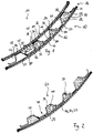
- the open sandwich structure 54 is in 2 shown.
- the further functional elements 32 can now be introduced into cavities 42 and thus the fuselage panel 10 can be fully equipped with functional elements 32 .
- very different systems can be integrated into the fuselage panel 10 .
- the open sandwich structure 54 is closed with the inner panel 24 . This also takes place with an assembly process based on a second functional layer 48, in which case the film 50 with the detachable adhesive 52 can also be used.
- connection-establishing functional layer 46 can be used for disassembly or repair.
- the functional layer 46, 48 be heated and dissolved. In this way, the functional elements 32 integrated in the filling panel 30 can be reached.
Landscapes
- Engineering & Computer Science (AREA)
- Aviation & Aerospace Engineering (AREA)
- Mechanical Engineering (AREA)
- Manufacturing & Machinery (AREA)
- Transportation (AREA)
- Laminated Bodies (AREA)
Description
- Die Erfindung betrifft ein Herstellverfahren zum Herstellen eines tragenden Rumpfpaneels für einen Rumpfabschnitt eines Luftfahrzeugrumpfes im Bereich einer Kabine eines Luftfahrzeuges.
- Bisher erfolgt die Entwicklung, Konzeption und Herstellung von Luftfahrzeugen, wie insbesondere Verkehrsflugzeugen, derart, dass von einem Flugzeughersteller zunächst die tragende Rumpfstruktur konzipiert und hergestellt wird und dann je nach Anforderungen des Verkehrsflugzeuges die Kabine entworfen und in die Rumpfstruktur eingepasst wird. Demnach werden heutzutage bei den großen Flugzeugherstellern, wie beispielsweise bei der Fa. Airbus, der strukturelle Flugzeugrumpf und die Kabine inklusive deren Verkleidungselemente hin zu der Struktur des Flugzeugrumpfes separat gefertigt. Ebenso findet die Integration von Systemen, wie Flugsystemen, Unterhaltungssystemen, Klimatisierungssystemen, Steuerungssystemen, als separater Arbeitsschritt zwischen Strukturfertigung und Kabinenintegration statt. Dieses Konzept hat sich zwar hinsichtlich der Variabilität der Kabinen und der so gegebenen möglichen Einsatzzwecken bewährt, führt aber zu einer großen Komplexität der Fertigung.
- Zum Stand der Technik bezüglich Aufbau von Rumpfstrukturen für Luftfahrzeuge wird z.B. auf die
DE 10 2010 013 370 A1 , dieEP 2 411 280 B1 sowie auf Herbeck/Kindervater: Ein neues Designkonzept für einen CFK-Flugzeugrumpf; Werkstoffkolloquium 2006; Wettbewerb der Werkstoffe; DLR Werkstoffkolloquium 2006 verwiesen. -
WO 2012 / 152 934 A2 offenbart ein Paneel zur lösbaren Anordnung zwischen einer Außenhaut eines Transportmittels und einer Innenverkleidung des Transportmittels, mit einem plattenartigen Isolationskörper, der zumindest einen integrierten Klimakanal aufweist und zumindest eine zur Innenfläche abschnittsweise geöffnete nutenartige Leitungsführung hat, ein Verfahren zur Herstellung eines derartigen Paneels sowie ein Flugzeug mit einer Vielzahl von derartigen Paneelen. - Aus der
DE 10 2012 019 905 B3 ist ein Rumpfstrukturbauteil für ein Luftfahrzeug bekannt, welches eine tragende Innenhaut, eine nicht tragende Außenhaut und einen Sandwichkern dazwischen aufweist. Als Sandwichkern wird eine Schaumstoffschicht vorgeschlagen. Die Innenhaut ist auf ihrer Innenseite mit Spanten und Stringern und auf ihrer Außenseite mit Stringern versehen. -
US 5 985 362 A offenbart ein Isoliersystem für Rumpfwände eines Luftfahrzeugs. Die Isolierung wird durch einen aufgesprühten Schaum gebildet der gegen ein Barrierematerial und gegen die Innenseite der Außenhaut über jegliche nach einwärts vorspringende Strukturelemente gesprüht ist. - Aus der
DE 10 2009 015 856 A1 ist ein Rumpfsegment für ein Luftfahrzeug und ein Verfahren zum Herstellen des Rumpfsegments bekannt. Das Rumpfsegment ist mit einer Außenhaut und einer Innenhaut versehen, die über einen Kern voneiander beabstandet sind. In den Kern sind Leitungskanäle zur Systemintegration integriert. - Aus der nachveröffentlichten
EP2 857 186 A2 ist ein Verfahren zur Herstellung eines Faserverbundbauteils und einer Strukturkomponente eines Luft- oder Raumfahrzeugs bekannt, bei dem ein Schaumkörper ausgebildet und mit Einbuchtungen versehen wird. In den Einbuchtungen werden verstärkende Elemente ausgebildet. Anschließend wird der Schaumkörper mit den darin ausgebildeten Elementen mit einem Hautabschnitt verbunden. - Aufgabe der Erfindung ist es, die Herstellung eines Luftfahrzeugrumpfes und die Wartung von Luftfahrzeugen zu vereinfachen.
- Zum Lösen dieser Aufgabe schlägt die Erfindung ein Herstellverfahren zum Herstellen eines tragenden Rumpfpaneels gemäß Anspruch 1 vor.
- Vorteilhafte Ausgestaltungen der Erfindung sind Gegenstand der Unteransprüche. Die Erfindung schafft gemäß einem ersten Aspekt ein Herstellverfahren zum Herstellen eines tragenden Rumpfpaneels gemäss Anspruch 1.
- Das Verfahren umfasst Schritte a) bis f), wobei in der gesamten hiesigen Offenbarung einschließlich der Ansprüche die Bezeichnungen der Schritte mit a) bis f) oder mit zusätzlichen Nummern lediglich zur einfacheren Bezugnahme gewählt ist und keinerlei Aussagen über eine bestimmte Reihenfolge der Schritte aussagt:
Vorzugsweise werden wenigstens zwei der Schritte a), c) und/oder d) zumindest zeitweise überschneidend und/oder parallel durchgeführt. - Vorzugsweise enthält Schritt a) den Schritt:
a1) Vormontieren des Füllpaneels. - Vorzugsweise enthält Schritt a) den Schritt:
a2) Fertigen des Füllpaneels aus Verbundwerkstoff oder Verbundwerkstoffen. - Vorzugsweise enthält Schritt a) den Schritt:
a3) Fertigen des Füllpaneels aus Profilelementen aus einem flächigen Material und Füllmaterial. - Vorzugsweise enthält Schritt a) den Schritt:
a4) Versehen des Füllpaneels mit einem Kernwerkstoff, insbesondere einem strukturellen Schaum. - Vorzugsweise enthält Schritt a) den Schritt:
a5) Versehen des Füllpaneels mit Vorsprüngen und Hohlräumen. - Vorzugsweise enthält Schritt a) den Schritt:
a6) Versehen des Füllpaneels mit Fügeflächen, die für eine stoffschlüssige Verbindung mit wenigstens einer der Schalen vorbereitet werden. - Vorzugsweise enthält Schritt a) wenigstens einen der Schritte:
- a7.1) Fertigen des Füllpaneels in RTM-Technologie oder
- a7.2) Fertigen des Füllpaneels in voll thermoplastischer Composite-Bauweise.
- Vorzugsweise enthält Schritt a) den Schritt:
a8) Fertigen des Füllpaneels mit Omegaprofilen mit Schaumanteil. - Erfindungsgemäß entält Schritt b) den Schritt:
b1) Vormontieren wenigstens eines Funktionselements der Rumpfstruktur und/oder der Kabine in das Füllpaneel vor Durchführung der Schritte e) und f). - Vorzugsweise enthält Schritt b) den Schritt:
b2) Einbringen wenigstens eines Funktionselements der Rumpfstruktur und/oder der Kabine zwischen den Schritten e) und f) in das an das eine Rumpfbauelement befestigte Füllpaneel. - Vorzugsweise enthält Schritt b) den Schritt:
b3) Einbau wenigstens einer Systemkomponente eines Kabinensystems, eines Flugsystems und/oder eines Rumpfstruktursystems als Funktionselement in wenigstens einen Hohlraum des Füllelements. - Vorzugsweise enthält Schritt b) den Schritt:
b4) Einbringen wenigstens eines Funktionselements in wenigstens einen Hohlraum des Füllelements und Verfüllen des Hohlraums mit einem Isolationsmaterial und/oder Überdecken des Hohlraumes mit einer Schale im Rahmen der Durchführung wenigstens einer der Schritte e) und f). - Vorzugsweise enthält Schritt c) den Schritt:
c1) Fertigen der Außenhaut aus einem Metallmaterial. - Vorzugsweise enthält Schritt c) den Schritt:
c2) Fertigen der Außenhaut aus einem Verbundwerkstoff. Besonders bevorzugt wird die Außenhaut aus oder unter Verwendung eines Faserverbundwerkstoffs, wie z.B. CFK, gefertigt. - Vorzugsweise enthält Schritt c) den Schritt:
c3) Fertigen der Außenhaut mit einer Blitzschutzeinrichtung. - Für weitere Einzelheiten zu möglichen Blitzschutzeinrichtungen wird auf die
DE 10 2011 112 518 A1 oder dieDE 10 2006 046 002 A1 verwiesen. - Vorzugsweise enthält Schritt c) den Schritt:
c4) Fertigen der Außenhaut derart, dass Beschädigungsschutzanforderungen des Luftfahrzeugs erfüllt werden. Dies kann z.B. durch Ausrüsten der Außenhaut mit einer Beschädigungs-, Belastungs- und/oder Ermüdungsüberwachungseinrichtung oder durch gesonderte Fertigung der Struktur der Außenhaut entsprechend des Einsatzortes, z.B. mittels kraftflussgerechtem Faserverlauf von Fasern einer Faserverbundstruktur, durch Einsatz von Taylored Blanks mit entsprechend variablen Dicken usw. geschehen. - Für weitere Einzelheiten zu einer möglichen Beschädigungs-, Belastungs- und/oder Ermüdungsüberwachungseinrichtung wird ausdrücklich auf die
WO 2012/010496 ,WO 2012/055699 A1 ,DE 10 2008 003 498 A1 und dieWO 2009/071602 A2 verwiesen. - Vorzugsweise enthält Schritt d) den Schritt:
d1) Fertigen des Innenpaneels mit einer vorbestimmten Brandschutzeigenschaft. Insbesondere kann das Innenpaneel in Brandschutzausführung, z.B. durch entsprechende Materialauswahl, durch zusätzliches Vorsehen von Brandschutzmaterialien oder dergleichen gefertigt werden. Von besonderem Vorteil ist, dass das Innenpaneel aufgrund der Integration von Funktionselementen in das Füllpaneel mit entsprechend weniger Durchbrechungen oder Unterbrechungen, die ansonsten womöglich einer besonderen Brandschutzmaßnahme - wie z.B. Brandschott - bedürften, ausgebildet werden kann. - Vorzugsweise enthält Schritt d) den Schritt:
d2) Fertigen des Innenpaneels derart, dass Brandschutzanforderungen der Kabine erfüllt werden. - Vorzugsweise enthält Schritt d) den Schritt:
d3) Fertigen des Innenpaneels derart, dass es als Außenabschluss der Kabine zur Rumpfstruktur hin geeignet ist. - Vorzugsweise enthält Schritt e) den Schritt:
e1) stoffschlüssiges Verbinden des Füllpaneels mit der einen Schale. - Vorzugsweise enthält Schritt e) den Schritt:
e2) Verbinden des Füllpaneels mit der einen Schale durch Erzeugung kovalenter Bindungen. Vorzugsweise wird in einem Fügeverfahren eine Verbindung verwendet, die ko-valente Bindungen erzeugt, z.B. ein Diffusions-Bonding von TP zu TP. - Vorzugsweise enthält Schritt e) den Schritt:
e3) Anordnen des Füllpaneels mit offenen Hohlräumen, so dass eine offene Sandwichstruktur zum Einbringen von Funktionselementen in das Füllpaneel entsteht. - Vorzugsweise enthält Schritt e) den Schritt:
e4) Verkleben des Füllpaneels an vorbereiteten Fügeflächen des Füllpaneels mit der einen Schale. - Vorzugsweise enthält Schritt e) den Schritt:
e5) lösbares Verbinden des Füllpaneels mit der einen Schale. - Vorzugsweise enthält Schritt e) den Schritt:
e6) lösbares Befestigen des Füllpaneels an die eine Schale mittels einer Funktionsschicht. - Vorzugsweise enthält Schritt e) den Schritt:
e7) lösbares Befestigen des Füllpaneels an die eine Schale mittels eines sich unter einer Lösebehandlung - wie z.B. Erwärmen - lösenden Klebemittels. - Vorzugsweise enthält Schritt e) den Schritt:
e8) Befestigen des Füllpaneels zunächst nur an die Außenhaut. - Vorzugsweise enthält Schritt f) den Schritt:
f1) stoffschlüssiges Verbinden des Füllpaneels mit der anderen Schale. - Vorzugsweise enthält Schritt f) den Schritt:
f2) Verbinden des Füllpaneels mit der anderen Schale durch Erzeugung kovalenter Bindungen. Vorzugsweise wird in einem Fügeverfahren eine Verbindung verwendet, die ko-valente Bindungen erzeugt, z.B. ein Diffusions-Bonding von TP zu TP. - Vorzugsweise enthält Schritt f) den Schritt:
f3) Verkleben des Füllpaneels an vorbereiteten Fügeflächen des Füllpaneels mit der anderen Schale. - Vorzugsweise enthält Schritt f) den Schritt:
f4) lösbares Verbinden des Füllpaneels mit der andere Schale. - Vorzugsweise enthält Schritt f) den Schritt:
f5) lösbares Befestigen des Füllpaneels an die andere Schale mittels einer weiteren Funktionsschicht. - Vorzugsweise enthält Schritt f) den Schritt:
f6) lösbares Befestigen des Füllpaneels an die andere Schale mittels eines sich unter einer Lösebehandlung lösenden Klebemittels. - Vorzugsweise enthält Schritt f) den Schritt:
f7) Befestigen des Innenpaneels an das Füllelement, nachdem zunächst das Füllelement an die Außenhaut befestigt worden ist. - Vorzugsweise enthält Schritt f) den Schritt:
f8) Verschließen einer durch Hohlräume des Füllpaneels gebildeten offenen Sandwichstruktur, nachdem wenigstens ein Funktionselement in den Hohlraum eingebracht worden ist. - Mit dem Verfahren gemäß Ausführungsformen der Erfindung lässt sich ein tragendes Rumpfpaneel zum Bilden eines Rumpfabschnitts als Teil der Tragstruktur eines Luftfahrzeugrumpfes in einem Bereich einer Kabine eines Luftfahrzeuges herstellen, wobei das Rumpfpaneel in Sandwichbauweise mit einem Innenpaneel und einer Außenhaut als Schalen und einem zwischen den Schalen eingebetteten Füllpaneel als Kern ausgebildet ist, wobei die Außenhaut als Teil einer Rumpfstruktur und der äußeren Begrenzung des Luftfahrzeugrumpfes ausgebildet ist, wobei das Innenpaneel für eine Innenraumbegrenzung der Kabine ausgebildet ist und wobei Funktionselemente der Rumpfstruktur und der Kabine oder des Luftfahrzeugs in das Füllpaneel integriert sind und wobei das Füllpaneel mit darin integrierten Stegen, Spanten, und/oder Rippen als Funktionselemente zum tragenden Aufbau der Rumpfstruktur versehen und separat gefertigt ist, wobei beim Fertigen der Außenhaut und/oder des Innenpaneels mindestens eine der Schalen mit einer Positionierhilfe zum Positionieren des Füllpaneels versehen ist.
- Bei einer vorteilhaften Verwendung des Verfahrens wird einen Luftfahrzeugrumpf oder eine Luftfahrzeugkabine, mit einem derartigen Rumpfpaneel versehen.
- Besondere Vorteile bevorzugter Ausgestaltungen der Erfindung werden im Folgenden näher erläutert.
- In der traditionellen Fertigung von Flugzeugrumpfen und deren Kabine werden der strukturelle Flugzeugrumpf und die Kabine inklusive deren Verkleidungselemente hin zur Struktur separat gefertigt. Ebenso findet die Systemintegration als separater Arbeitsschritt zwischen Strukturfertigung und Kabinenintegration statt. Im Gegensatz zu dieser traditionellen Entwicklungsweise und Fertigungsweise ist es mit der Erfindung möglich, während der Fertigung der Tragstruktur bereits Funktionselemente der Kabine bzw. bereits Funktionselemente der Tragstruktur oder auch Funktionselemente anderer Systeme des Luftfahrzeuges zu integrieren und die Struktur und die Kabinenfertigung in ein Gesamtkonzept zu überführen.
- Bisher wurden jeweils einzelne Funktionalitäten in die Rumpfstruktur integriert, jedoch fehlt die Einbettung in ein übergreifendes Gesamtkonzept zur Rumpffertigung inklusive der Kabinenintegration und System integration zur übergreifenden Funktionsintegration.
- Bei einer besonders bevorzugten Ausgestaltung des Herstellverfahrens findet während der Herstellung einer tragenden Sandwichstruktur für einen Luftfahrzeugrumpf, wie insbesondere einen Flugzeugrumpf, die Funktionsintegration statt. Es werden bereits bei der Entwicklung der Sandwichstruktur für den Flugzeugrumpf, z.B. Kabinenanforderungen, Systeminstallationen und Außenhautfertigung, in einem gemeinsamen Entwicklungs- und Herstellungskonzept integriert.
- Es entsteht somit ein tragendes Rumpfpaneel, welches direkt die Funktion der Kabine, z.B. Brandschutzeigenschaft, der Systeminstallation und Wartbarkeit der Systeme sowie die strukturellen Eigenschaften der Außenhaut inklusive z.B. von Blitzschutzintegration oder sonstiger Anforderungen für die Außenhaut erfüllt.
- Die Erweiterung der Bauweise - Berücksichtigung von Kabinenanforderungen bereits bei der Rumpffertigung bzw. Berücksichtigung von Anforderungen der Tragstruktur bei der Kabinenfertigung - kann auch dazu führen, dass auch Crash-Elemente in die Struktur eingearbeitet werden können.
- Vorzugsweise werden durch das Konzept einfache, sektionsweise Modifikationen und Reparaturen möglich, was die Long-Life-Kosten eines Fluggerätes senken und die Recycling-Fähigkeit erhöhen wird.
- Durch eine mögliche Nutzung von funktionsintegrierten Werkstoffsystemen bereits im Bauweisenkonzept und im Fertigungskonzept wird zusätzlich in einen Rumpf eingebrachtes Gewicht vermieden, welches durch die traditionelle separate Betrachtung der einzelnen Arbeitsabläufe eingebracht wird.
- Zum Beispiel lässt sich durch eine Reduktion von Niet- und Schraubenverbindung und eine Überführung in Klebeverbindungen oder dergleichen eine deutliche Gewichts- und Kosteneinsparung erreichen.
- Das Strukturkonzept einer Gesamtintegration der Fertigung von Rumpfstruktur und Kabinenelementen kann Arbeitsabläufe der Systemintegration vereinfachen und zusammenfassen, und somit können Kosten bei der Fertigung gespart werden.
- Ein Ausführungsbeispiel der Erfindung wird hiernach anhand der Zeichnungen näher erläutert. Darin zeigt:
- Fig. 1
- eine Schnittdarstellung durch ein tragendes Rumpfpaneel in Sandwichbauweise zum Aufbau eines einen Teil einer Außenwandung einer Kabine und gleichzeitig einen Teil einer tragenden Rumpfstruktur bildenden Rumpfpaneels;
- Fig. 2
- eine Ansicht vergleichbar von
Fig. 1 einer Vorstufe bei der Fertigung des Rumpfpaneels vonFig. 1 . -
Fig. 1 zeigt ein Rumpfpaneel 10 zum Bilden eines Teils einer tragenden Rumpfstruktur 12 und einer Außenwandung einer Kabine 14 eines Luftfahrzeuges, wie beispielsweise eines Flugzeuges. Das Rumpfpaneel 10 ist in Sandwichbauweise bzw. als Sandwichelement 16 mit einer inneren Schale 18, einer äußeren Schale 20 und einem Kern 22 dazwischen ausgebildet. - Die innere Schale 18 wird durch ein Innenpaneel 24 gebildet, das zum Bilden einer Innenraumbegrenzung 26 der Kabine 14 dient.
- Die äußere Schale 20 ist durch eine Außenhaut 28 gebildet, die zum Bilden eines Teils der Rumpfstruktur 12 und der äußeren Begrenzung des Luftfahrzeugrumpfes dient.
- Der Kern 22 ist durch ein Füllpaneel 30 gebildet, in welches Funktionselemente 32 der Rumpfstruktur 12, der Kabine 14 oder eines sonstigen Systems des Luftfahrzeugs integriert sind.
- Demnach ist das Rumpfpaneel 10 im Wesentlichen prinzipiell aus drei Kernelementen aufgebaut. Die Außenhaut 28 und das Innenpaneel 24 bilden die Schalen 18, 20. Durch einen Montageprozess werden die beiden Schalen 18, 20 miteinander verbunden, wobei die vormontierten Füllpaneele 30 zum Einsatz kommen.
- Diese vormontierten Füllpaneele 30 werden z.B. in Verbundwerkstoffweise, wie z.B aus CFK-Werkstoffen, ausgeführt und beinhalten einen Kernwerkstoff 34 sowie vorbereitete Fügeflächen 36 zur Verbindung des Füllpaneels 30 mit den Schalen 18, 20.
- Die Ausführung der Fügeflächen erfolgt derart, dass es bei der Fusion der Bauteile zu einer Materialverbindung auf Polymerebene kommt.
- Die Herstellung des Füllpaneels 30 kann mittels einer RTM-Technologie erfolgen. "RTM" steht für Resin Transfer Moulding, zu Deutsch etwa "Spritzpressen". Das Resin Transfer Moulding ist ein Verfahren zur Herstellung von Formteilen aus Duroplasten und/oder Elastomeren. Im Vergleich zum Pressen wird hierbei die Formmasse mittels Kolben oder dergleichen Einspritzeinrichtungen von einer meist vorbeheizten Vorkammer über Verteilerkanäle in ein Formnest eingespritzt, worin sie unter Wärme und Druck aushärtet.
- Die Herstellung der Füllpaneele 30 kann insbesondere mittels einer RTM-Technologie auch in großer Stückzahl erfolgen, so dass auch hohe Rumpfkadenzen erreichbar sind. Mit Hilfe der RTM-Methode ist es auch möglich, die entsprechenden Schnittstellen zur Einstellung der Fügeflächen 36 herzustellen.
- Durch ein RTM-Verfahren kann z.B. ein einstückig ausgebildetes Füllpaneel 30 aus integriertem, strukturellem Schaum 38, welcher in ausgehärtetem Zustand zur Übertragung von Kräften und Lasten fähig ist, ausgebildet werden.
- Die Herstellung der Füllpaneele 30 kann natürlich aber auch auf andere Art und Weise erfolgen, wie z.B. in voll thermoplastischer Composite-Bauweise.
- Das Funktionselement 32 ist insbesondere mit Vorsprüngen 40 mit Fügeflächen 36 an deren Endflächen und Hohlräumen 42 dazwischen ausgebildet.
- Die Hohlräume 42 können zum Aufnehmen der Funktionselemente 32 dienen und können bei der Herstellung einer Systeminstallation mit Isolationsmaterial (nicht dargestellt) aufgefüllt werden.
- Der verwendete Werkstoff des strukturellen Schaums 38 kann ebenfalls isolierende Eigenschaften aufzeigen.
- Eine derartige Bauweise ermöglicht es,
- a) das Innenpaneel derart auszuführen, dass Brandschutzanforderungen der Kabine 14 eines Luftfahrzeuges erfüllt werden;
- b) die Außenhaut 28 derart auszuführen, dass auch Blitzschutz- und Beschädigungsschutz-Anforderungen eines Luftfahrzeuges erfüllt werden; und
- c) die Füllpaneele 30 in vormontierter Weise derart zu fertigen, dass sie Systemfunktionen tragen.
- Da die Füllpaneele 30 in einem separaten Prozess gefertigt werden können, können verschiedene Ausführungen vorkommen.
- In dem dargestellten Ausführungsbeispiel sind neben dem strukturellen Schaum 38 auch Profilelemente 44 angedeutet, die tragende Aufgaben mit übernehmen.
- Insbesondere können durch den strukturellen Schaum 38 und/oder Profilelemente 44 - eventuell in Kombination mit einzusetzenden Spanten - die Rumpflasten übertragen werden.
- Beispielsweise können teilweise Omegaprofile mit Schaumanteil oder auch einfache Rippen in dem Füllpaneel 30 vorkommen. Ebenfalls können Knotenpunkte in dem Füllpaneel 30 realisiert werden.
- Dadurch lassen sich sowohl tragende Funktionselemente 32 - beispielsweise die Profilelemente 44 - als auch isolierende Funktionselemente 32 durch den strukturellen Schaum 38 und/oder das auszufüllende Isoliermaterial - und auch weitere Funktionselemente 32, wie z.B. Klimatisierungselemente, Luftführungskanäle, Kabelkanäle, Verkabelungen usw. allesamt in dem Füllpaneel 30 integrieren.
- Im Folgenden wird ein möglicher Montageprozess für das in
Fig. 1 dargestellte Rumpfpaneel 10 näher erläutert. - Ein Montageprozess erfolgte vorzugsweise derart, dass die äußere Schale 20, gebildet durch die Außenhaut 28, derart gefertigt wird, dass bereits Positionierhilfen (nicht dargestellt) für die vormontierten Füllpaneele 30 eingebaut sind und entsprechende Vorbereitungen zur "Fusion" der Außenhaut 28 mit den vormontierten Füllpaneelen 30 vorliegt.
- Die Außenhaut 28 kann z.B. aus Composite-Materialien, wie insbesondere CFK-Materialien, oder aus metallischen Werkstoffen oder aus Mischformen (z.B. Metall und CFK) bestehen oder aufgebaut sein.
- In einem parallelen Schritt wird das Innenpaneel 24 gefertigt, welches vorzugsweise ebenfalls Positionierhilfen (nicht dargestellt) trägt und - wie oben beschrieben - die entsprechenden Eigenschaften für die Nutzung als Kabine 14 aufweist.
- Die vorzugsweise vormontierten Füllpaneele 30 werden ebenfalls gefertigt und entsprechend mit Systemfunktion ausgerüstet. Zum Beispiel können bereits Kabel, Isolierungen, Lüftungen usw. in das Füllpaneel 30 bei dessen Fertigung integriert werden. Diese Füllpaneele 30 sind vorzugsweise in Verbundmaterialien, wie insbesondere CFK oder dergleichen Composite, auszuführen, um Wärmebrücken zwischen Innenpaneel 24 und Außenhaut 28 zu vermeiden.
- Die Montage erfolgt nun vorzugsweise mittels einer eingearbeiteten Funktionsschicht 46, 48. Zum Beispiel wird eine Folie aus zum stoffschlüssigen Verbinden der Schalen 18, 20 mit dem Füllpaneel 30 geeigneten Material vorgesehen. Vorzugsweise wird die Funktionsschicht 46, 48 derart ausgebildet, dass ein Lösen der Verbindung durch eine spezielle Behandlung möglich ist. Beispielsweise wird die Folie aus einem warmschmelzenden Klebemittel 52 hergestellt.
- Die Funktionsschicht 46, 48 ermöglicht eine strukturelle Verbindung zwischen den Schalen 18, 20 und dem vormontierten Füllpaneel 30.
- Hierzu wird vorzugsweise zunächst das Füllpaneel 30 mit einer ersten Funktionsschicht 46 mit der Außenhaut 28 verbunden. Es entsteht nun eine offene Sandwichstruktur, wobei die Hohlräume 42 noch frei liegen.
- Die offene Sandwichstruktur ermöglicht es, weiter Systeme in den Rumpf zu installieren. Die offene Sandwichstruktur 54 ist in
Fig. 2 dargestellt. - Insbesondere können nun die weiteren Funktionselemente 32 in Hohlräume 42 eingebracht werden und somit das Rumpfpaneel 10 fertig mit Funktionselementen 32 ausgerüstet werden. Dadurch lassen sich ganz unterschiedliche Systeme in das Rumpfpaneel 10 integrieren.
- Ist die Ausrüstung erfolgt, wird die offene Sandwichstruktur 54 mit dem Innenpaneel 24 geschlossen. Dieses erfolgt ebenfalls mit einem Montageprozess basierend auf einer zweiten Funktionsschicht 48, wobei ebenfalls die Folie 50 mit dem lösbaren Klebemittel 52 eingesetzt werden kann.
- Zur Demontage oder Reparatur kann die verbindungsherstellende Funktionsschicht 46 genutzt werden. Beispielsweise bei Verwendung eines heißschmelzenden Klebemittels als Werkstoff für die Folie 50 kann die Funktionsschicht 46, 48 erwärmt und gelöst werden. So kann man die in dem Füllpaneel 30 integrierten Funktionselemente 32 erreichen.
-
- 10
- Rumpfpaneel
- 12
- Rumpfstruktur
- 14
- Kabine
- 16
- Sandwichelement
- 18
- innere Schale
- 20
- äußere Schale
- 22
- Kern
- 24
- Innenpaneel
- 26
- Innenraumbegrenzung
- 28
- Außenhaut
- 30
- Füllpaneel
- 32
- Funktionselement
- 34
- Kernwerkstoff
- 36
- Fügefläche
- 38
- struktureller Schaum
- 40
- Vorsprung
- 42
- Hohlraum
- 44
- Profilelement
- 46
- erste Funktionsschicht
- 48
- zweite Funktionsschicht
- 50
- Folie
- 52
- Klebemittel
- 54
- offene Sandwichstruktur
Claims (7)
- Herstellverfahren zum Herstellen eines tragenden Rumpfpaneels (10) für einen Rumpfabschnitt eines Luftfahrzeugrumpfes in einem Bereich einer Kabine (14) eines Luftfahrzeuges, mit:Anfertigen des Rumpfpaneels (10) in Sandwichbauweise mit einem Innenpaneel (24) und einer Außenhaut (28) als Schalen (18, 20) und einem zwischen den Schalen (18, 20) eingebetteten Füllpaneel (30) als Kern (22), unter Ausbilden der Außenhaut (28) als Teil einer Rumpfstruktur (12) und der äußeren Begrenzung des Luftfahrzeugrumpfes,Ausbilden des Innenpaneels (24) für eine Innenraumbegrenzung (26) der Kabine (14),Integration von Funktionselementen (32) der Rumpfstruktur (12) und integration von Funktionselementen (32) der Kabine (14) und/oder des Luftfahrzeugs in das Füllpaneel (30), wobei das Verfahren die Schritte umfasst:a) Entwerfen und separates Fertigen des Füllpaneels (30) derart, dass es zur Aufnahme von Funktionselementen (32) der Rumpfstruktur (12) und zur Aufnahme von Funktionselementen (32) der Kabine (14) und/oder des Luftfahrzeuges ausgebildet ist,b) Versehen des Füllpaneels (30) mit Funktionselementen (32) der Kabine (14) und/oder des Luftfahrzeuges, Versehen des Füllpaneels (30) im Laufe der Fertigung gemäß Schritt a) mit Stegen, Spanten und/oder Rippen als Funktionselemente (32) zum tragenden Aufbau der Rumpfstruktur (12),c) Fertigen der Außenhaut (28) als Schale (18, 20) des Rumpfpaneels (10),d) Fertigen des Innenpaneels (24) als Schale (18, 20) des Rumpfpaneels (10),e) Befestigen des Füllpaneels (30) an eine der Schalen (18, 20) undf) Befestigen der anderen Schale (18, 20) an dem Füllpaneel (30),wobei beim Fertigen gemäß Schritt c) und/oder Schritt d) mindestens eine der Schalen (18, 20) mit einer Positionierhilfe zum Positionieren des Füllpaneels (30) versehen ist,
wobei Schritt b) den Schritt enthält:
b1) Vormontieren der Stege (12), Spanten (13) und/oder Rippen als Funktionselemente (32) der Rumpfstruktur (12) in das Füllpaneel (30) vor den Schritten e) und f). - Herstellverfahren nach Anspruch 1,
dadurch gekennzeichnet,
dass Schritt a) wenigstens einen, mehrere oder alle der Schritte enthält:a1) Vormontieren des Füllpaneels (30),a2) Fertigen des Füllpaneels (30) aus Verbundwerkstoff oder Verbundwerkstoffen;a3) Fertigen des Füllpaneels (30) aus Profilelementen (44) aus einem flächigen Material und Füllmaterial;a4) Versehen des Füllpaneels (30) mit einem Kernwerkstoff (34), insbesondere einem strukturellen Schaum (38);a5) Versehen des Füllpaneels (30) mit Vorsprüngen (40) und Hohlräumen (42);a6) Versehen des Füllpaneels (30) mit Fügeflächen (36), die für eine stoffschlüssige Verbindung mit wenigstens einer der Schalen (18, 20) vorbereitet werden;a7.1) Fertigen des Füllpaneels (30) in RTM-Technologie;a7.2) Fertigen des Füllpaneels (30) in voll thermoplastischer Composite-Bauweise; und/odera8) Fertigen des Füllpaneels (30) mit Omegaprofilen mit Schaumanteil. - Herstellverfahren nach einem der Ansprüche 1 oder 2,
dadurch gekennzeichnet,
dass Schritt b) wenigstens einen, mehrere oder alle der Schritte enthält:b2) Einbringen wenigstens eines Funktionselements (32) der Rumpfstruktur (12) und/oder der Kabine (14) zwischen den Schritten e) und f) in das an das eine Rumpfbauelement befestigte Füllpaneel (30);b3) Einbau wenigstens einer Systemkomponente eines Kabinensystems, eines Flugsystems und/oder eines Rumpfstruktursystems als Funktionselement (32) in wenigstens einen Hohlraum (42) des Füllelements; und/oderb4) Einbringen wenigstens eines Funktionselements (32) in wenigstens einen Hohlraum (42) des Füllelements und Verfüllen des Hohlraums (42) mit einem Isolationsmaterial und/oder Überdecken des Hohlraumes (42) mit einer Schale (18, 20) im Rahmen der Durchführung wenigstens einer der Schritte e) und f). - Herstellverfahren nach einem der Ansprüche 1 bis 3,
dadurch gekennzeichnet,
dass Schritt c) wenigstens einen, mehrere oder alle der Schritte enthält:c1) Fertigen der Außenhaut (28) aus einem Metallmaterial;c2) Fertigen der Außenhaut (28) aus einem Verbundwerkstoff, insbesondere Faserverbundwerkstoff;c3) Fertigen der Außenhaut (28) mit einer Blitzschutzeinrichtung;c4) Fertigen der Außenhaut (28) derart, dass Beschädigungsschutzanforderungen des Luftfahrzeugs erfüllt werden, insbesondere durch Ausrüsten der Außenhaut (28) mit einer Beschädigungs- oder Ermüdungsüberwachungseinrichtung. - Herstellverfahren nach einem der Ansprüche 1 bis 4,
dadurch gekennzeichnet,
dass Schritt d) einen, mehrere oder alle der folgenden Schritte aufweist:d1) Fertigen des Innenpaneels (24) mit einer vorbestimmten Brandschutzeigenschaft;d2) Fertigen des Innenpaneels (24) derart, dass Brandschutzanforderungen der Kabine (14) erfüllt werden;d3) Fertigen des Innenpaneels (24) derart, dass es als Außenabschluss der Kabine (14) zur Rumpfstruktur (12) hin geeignet ist. - Herstellverfahren nach einem der Ansprüche 1 bis 5,
dadurch gekennzeichnet,
dass Schritt e) einen mehrere oder alle der folgenden Schritte enthält:e1) stoffschlüssiges Verbinden des Füllpaneels (30) mit der einen Schale (18);e2) Verbinden des Füllpaneels (30) mit der einen Schale (18) unter Erzeugung kovalenter Bindungen;e3) Anordnen des Füllpaneels (30) mit offenen Hohlräumen (42), so dass eine offene Sandwichstruktur (54) zum Einbringen von Funktionselementen (32) in das Füllpaneel (30) entsteht;e4) Verkleben des Füllpaneels (30) an vorbereiteten Fügeflächen (36) des Füllpaneels (30) mit der einen Schale (18);e5) lösbares Verbinden des Füllpaneels (30) mit der einen Schale (18);e6) lösbares Befestigen des Füllpaneels (30) an die eine Schale (18) mittels einer Funktionsschicht (46, 48);e7) lösbares Befestigen des Füllpaneels (30) an die eine Schale (18) mittels eines sich unter einer Lösebehandlung lösenden Klebemittels (52); und/odere8) Befestigen des Füllpaneels (30) zunächst nur an die Außenhaut (28). - Herstellverfahren nach einem der Ansprüche 1 bis 6,
dadurch gekennzeichnet,
dass Schritt f) einen mehrere oder alle der folgenden Schritte enthält:f1) stoffschlüssiges Verbinden des Füllpaneels (30) mit der anderen Schale (20);f2) Verbinden des Füllpaneels (30) mit der anderen Schale (20) unter Erzeugung kovalenter Bindungen;f3) Verkleben des Füllpaneels (30) an vorbereiteten Fügeflächen (36) des Füllpaneels (30) mit der anderen Schale (20);f4) lösbares Verbinden des Füllpaneels (30) mit der anderen Schale (20);f5) lösbares Befestigen des Füllpaneels (30) an die andere Schale (20) mittels einer weiteren Funktionsschicht (48);f6) lösbares Befestigen des Füllpaneels (30) an die andere Schale (20) mittels eines sich unter einer Lösebehandlung lösenden Klebemittels (52); und/oderf7) Befestigen des Innenpaneels (24) an das Füllelement, nachdem zunächst das Füllelement an die Außenhaut (28) befestigt worden ist;f8) Verschließen einer durch Hohlräume (42) des Füllpaneels (30) gebildeten offenen Sandwichstruktur (54), nachdem wenigstens ein Funktionselement (32) in den Hohlraum (42) eingebracht worden ist.
Applications Claiming Priority (2)
| Application Number | Priority Date | Filing Date | Title |
|---|---|---|---|
| DE102013021066.6A DE102013021066A1 (de) | 2013-12-18 | 2013-12-18 | Herstellverfahren zum Herstellen eines tragenden Rumpfpaneels sowie damit herstellbares Rumpfpaneel |
| PCT/DE2014/000601 WO2015090263A1 (de) | 2013-12-18 | 2014-11-26 | Herstellverfahren zum herstellen eines tragenden rumpfpaneels sowie damit herstellbares rumpfpaneel |
Publications (2)
| Publication Number | Publication Date |
|---|---|
| EP3083394A1 EP3083394A1 (de) | 2016-10-26 |
| EP3083394B1 true EP3083394B1 (de) | 2022-07-27 |
Family
ID=52391719
Family Applications (1)
| Application Number | Title | Priority Date | Filing Date |
|---|---|---|---|
| EP14828127.2A Active EP3083394B1 (de) | 2013-12-18 | 2014-11-26 | Herstellverfahren zum herstellen eines tragenden rumpfpaneels sowie damit herstellbares rumpfpaneel |
Country Status (6)
| Country | Link |
|---|---|
| US (1) | US20160368586A1 (de) |
| EP (1) | EP3083394B1 (de) |
| CN (1) | CN106029494B (de) |
| CA (1) | CA2932368A1 (de) |
| DE (1) | DE102013021066A1 (de) |
| WO (1) | WO2015090263A1 (de) |
Families Citing this family (8)
| Publication number | Priority date | Publication date | Assignee | Title |
|---|---|---|---|---|
| EP2979975B1 (de) * | 2014-07-30 | 2017-09-27 | AIRBUS HELICOPTERS DEUTSCHLAND GmbH | Flugzeug mit einer Rahmenstruktur mit mindestens einem Hohlrahmen |
| DE102015220642A1 (de) * | 2015-10-22 | 2017-04-27 | Airbus Defence and Space GmbH | Strukturanordnung, Luft- oder Raumfahrzeug und Verfahren zum Herstellen einer Strukturanordnung |
| KR20200141052A (ko) * | 2018-04-05 | 2020-12-17 | 젠더 그룹 인터내셔널 아게 | 운송수단용 교환기 요소 및 이러한 교환기 요소가 구비된 운송수단 |
| DE102018207763A1 (de) * | 2018-05-17 | 2019-11-21 | Airbus Operations Gmbh | Rumpfstruktur für ein Luftfahrzeug |
| FR3090573A1 (fr) * | 2018-12-20 | 2020-06-26 | Airbus Operations | Panneau de revêtement mural pour aéronef à isolation intégrée |
| RU202616U1 (ru) * | 2020-11-02 | 2021-03-01 | Федеральное государственное бюджетное образовательное учреждение высшего образования "Казанский национальный исследовательский технический университет им. А.Н. Туполева - КАИ" | Фюзеляж летательного аппарата из ферменного заполнителя |
| RU2768416C1 (ru) * | 2021-04-15 | 2022-03-24 | Акционерное общество «Обнинское научно-производственное предприятие «Технология» им. А.Г.Ромашина» | Термостойкая трехслойная сотовая конструкция |
| US20240262066A1 (en) | 2023-02-08 | 2024-08-08 | B/E Aerospace, Inc. | Continuous manufacturing method of acoustic transmission loss panels with resonator network cores |
Citations (1)
| Publication number | Priority date | Publication date | Assignee | Title |
|---|---|---|---|---|
| EP2857186A2 (de) * | 2013-09-16 | 2015-04-08 | Airbus Operations GmbH | Verfahren zur Herstellung einer Faserverbundkomponente, Faserverbundkomponente, sowie Strukturbauteil für ein Luft- oder Raumfahrzeug |
Family Cites Families (13)
| Publication number | Priority date | Publication date | Assignee | Title |
|---|---|---|---|---|
| US5985362A (en) * | 1997-12-22 | 1999-11-16 | Mcdonnell Douglas Corporation | Insulation system for transport aircraft |
| US7997529B2 (en) * | 2006-01-19 | 2011-08-16 | The Boeing Company | Compliant panel for aircraft |
| DE102006046002B4 (de) | 2006-09-27 | 2009-03-12 | Eads Deutschland Gmbh | Schichtsystem zum Blitzschutz von Bauteilen |
| DE102007058102B4 (de) | 2007-12-03 | 2016-02-04 | Airbus Defence and Space GmbH | Zustandsüberwachungssystem für ein Luftfahrzeug |
| DE102008003498B4 (de) | 2008-01-08 | 2022-09-01 | Airbus Defence and Space GmbH | Aufprallerfassungselement für ein Luftfahrzeug, damit aufgebaute Aufprallerfassungsvorrichtung sowie Verfahren zur Überwachung von Aufprallvorgängen auf ein Luftfahrzeug |
| DE102009014377A1 (de) | 2009-03-23 | 2010-09-30 | Airbus Deutschland Gmbh | Flugzeugstruktur mit in Strukturelemente integrierte Luftführungsschächte |
| DE102009015856B4 (de) * | 2009-04-01 | 2012-01-26 | Airbus Operations Gmbh | Rumpfsegment und Verfahren zur Herstellung des Rumpfsegments |
| DE102010013370B8 (de) | 2010-03-30 | 2013-12-12 | Eads Deutschland Gmbh | Wandbauteil für ein Luftfahrzeug |
| DE102010032093B4 (de) | 2010-07-23 | 2018-12-27 | Aed Engineering Gmbh | Überwachungsvorrichtung für Reparaturpatches, Reparaturkit sowie Verfahren zum Überwachen eines Reparaturpatches |
| DE102010049909A1 (de) | 2010-10-28 | 2012-05-03 | Eads Deutschland Gmbh | Instandhaltungsinformationsvorrichtung, Zustandssensor zur Verwendung darin sowie damit durchführbares Verfahren zur Entscheidungsfindung für oder gegen eine Instandhaltung |
| DE102011075774A1 (de) * | 2011-05-12 | 2012-11-15 | Airbus Operations Gmbh | Panel, verfahren zur herstellung eines panels und flugzeug |
| DE102011112518B4 (de) | 2011-05-27 | 2020-01-09 | Airbus Defence and Space GmbH | Verfahren zur Herstellung einer Oberflächenstruktur mit Blitzschutz sowie Fahrzeugbauteilherstellverfahren |
| DE102012019905B3 (de) * | 2012-10-10 | 2013-09-19 | Deutsches Zentrum für Luft- und Raumfahrt e.V. | Rumpfstrukturbauteil für Fahrzeuge, insbesondere für Luft- und/oder Raumfahrzeuge |
-
2013
- 2013-12-18 DE DE102013021066.6A patent/DE102013021066A1/de not_active Withdrawn
-
2014
- 2014-11-26 CN CN201480069041.4A patent/CN106029494B/zh active Active
- 2014-11-26 EP EP14828127.2A patent/EP3083394B1/de active Active
- 2014-11-26 WO PCT/DE2014/000601 patent/WO2015090263A1/de not_active Ceased
- 2014-11-26 CA CA2932368A patent/CA2932368A1/en not_active Abandoned
-
2016
- 2016-06-17 US US15/186,121 patent/US20160368586A1/en not_active Abandoned
Patent Citations (1)
| Publication number | Priority date | Publication date | Assignee | Title |
|---|---|---|---|---|
| EP2857186A2 (de) * | 2013-09-16 | 2015-04-08 | Airbus Operations GmbH | Verfahren zur Herstellung einer Faserverbundkomponente, Faserverbundkomponente, sowie Strukturbauteil für ein Luft- oder Raumfahrzeug |
Also Published As
| Publication number | Publication date |
|---|---|
| EP3083394A1 (de) | 2016-10-26 |
| CN106029494A (zh) | 2016-10-12 |
| CN106029494B (zh) | 2019-03-15 |
| US20160368586A1 (en) | 2016-12-22 |
| CA2932368A1 (en) | 2015-06-25 |
| WO2015090263A1 (de) | 2015-06-25 |
| DE102013021066A1 (de) | 2015-06-18 |
Similar Documents
| Publication | Publication Date | Title |
|---|---|---|
| EP3083394B1 (de) | Herstellverfahren zum herstellen eines tragenden rumpfpaneels sowie damit herstellbares rumpfpaneel | |
| EP2242682B1 (de) | VERFAHREN ZUM VERBINDEN VON ZWEI RUMPFSEKTIONEN UNTER SCHAFFUNG EINES QUERSTOßES SOWIE QUERSTOßVERBINDUNG | |
| DE102012000564B4 (de) | Urformwerkzeug und Verfahren für die Fertigung eines aus faserverstärktem Kunststoff bestehenden aerodynamisch geformten Luftfahrzeugbauteils | |
| DE102005059933B4 (de) | Flechttechnisch hergestelltes Faserverbundbauteil | |
| EP1957360B1 (de) | Luftfahrzeug-druckkabinentür aus faserverbundwerkstoff | |
| DE102007003277B4 (de) | Rumpf eines Luft- oder Raumfahrzeuges in CFK-Metall Hybridbauweise mit einem Metallrahmen | |
| DE102013218520A1 (de) | Verfahren zur Herstellung eines Faserverbundbauteils, Faserverbundbauteil, sowie Strukturbauteil für ein Luft- oder Raumfahrzeug | |
| EP2361753A1 (de) | Verfahren und Anordnung zur Herstellung eines einstückigen Hohlprofilbauteils mit Faserverbundwerkstoff | |
| EP1815969B1 (de) | Flugzeugbauteil sowie Verfahren zur Herstellung eines Flugzeugbauteiles | |
| DE102007033261A1 (de) | Faserverbundbauteil mit thermoplastischen Versteifungselementen | |
| DE102011101450B4 (de) | Flugzeugbaugruppe und Verfahren zur Herstellung einer Flugzeugbaugruppe | |
| EP2552774B1 (de) | Wandbauteil für ein luftfahrzeug | |
| DE102011102364A1 (de) | Freitragendes Kabinenstruktursegment | |
| EP3134254B1 (de) | Verfahren zum verbinden von verbindungsabschnitten von wenigstens zwei bauteilen und baugruppe | |
| DE102008059653B4 (de) | Flächiges Bauteil eines Fluggerätes und Verfahren zu dessen Herstellung | |
| DE102010003356B4 (de) | Verfahren zur Herstellung eines Bauteils aus einem Verbundmaterial und Komponente für ein Bauteil aus einem Verbundmaterial | |
| DE102011083162A1 (de) | Mehrlagiges Faserverbundbauteil und Verfahren zum Herstellen desselben | |
| DE102014102117B4 (de) | Verfahren und Verbindungsanordnung zum Verbinden eines Strömungskörper-Bauelementes mit einem oder mehreren Bauteilen | |
| DE102010042186A1 (de) | Verbund, Luft- oder Raumfahrzeug sowie Verfahren | |
| EP3580109A1 (de) | Dachsegmente für das dach eines wagenkastens | |
| AT517198A1 (de) | Steuerflächenelement für ein Flugzeug | |
| WO2017050578A1 (de) | Flächiges fahrkorbelement für eine aufzugsanlage | |
| EP3580052B1 (de) | Verbindungselement zur anbindung eines bauteils an eine faserverbundstruktur | |
| DE102005030939A1 (de) | Verfahren zur Herstellung eines im Wesentlichen schalenförmigen Bauteils | |
| DE102018112850A1 (de) | Bauteil mit verbundenen Faserverbundwerkstoff-Teilelementen sowie Verfahren und Vorrichtung zum Verbinden der Teilelemente |
Legal Events
| Date | Code | Title | Description |
|---|---|---|---|
| PUAI | Public reference made under article 153(3) epc to a published international application that has entered the european phase |
Free format text: ORIGINAL CODE: 0009012 |
|
| 17P | Request for examination filed |
Effective date: 20160530 |
|
| AK | Designated contracting states |
Kind code of ref document: A1 Designated state(s): AL AT BE BG CH CY CZ DE DK EE ES FI FR GB GR HR HU IE IS IT LI LT LU LV MC MK MT NL NO PL PT RO RS SE SI SK SM TR |
|
| AX | Request for extension of the european patent |
Extension state: BA ME |
|
| DAX | Request for extension of the european patent (deleted) | ||
| STAA | Information on the status of an ep patent application or granted ep patent |
Free format text: STATUS: EXAMINATION IS IN PROGRESS |
|
| 17Q | First examination report despatched |
Effective date: 20190426 |
|
| GRAP | Despatch of communication of intention to grant a patent |
Free format text: ORIGINAL CODE: EPIDOSNIGR1 |
|
| STAA | Information on the status of an ep patent application or granted ep patent |
Free format text: STATUS: GRANT OF PATENT IS INTENDED |
|
| INTG | Intention to grant announced |
Effective date: 20220303 |
|
| GRAS | Grant fee paid |
Free format text: ORIGINAL CODE: EPIDOSNIGR3 |
|
| GRAA | (expected) grant |
Free format text: ORIGINAL CODE: 0009210 |
|
| STAA | Information on the status of an ep patent application or granted ep patent |
Free format text: STATUS: THE PATENT HAS BEEN GRANTED |
|
| AK | Designated contracting states |
Kind code of ref document: B1 Designated state(s): AL AT BE BG CH CY CZ DE DK EE ES FI FR GB GR HR HU IE IS IT LI LT LU LV MC MK MT NL NO PL PT RO RS SE SI SK SM TR |
|
| REG | Reference to a national code |
Ref country code: CH Ref legal event code: EP |
|
| REG | Reference to a national code |
Ref country code: DE Ref legal event code: R096 Ref document number: 502014016328 Country of ref document: DE |
|
| REG | Reference to a national code |
Ref country code: AT Ref legal event code: REF Ref document number: 1506908 Country of ref document: AT Kind code of ref document: T Effective date: 20220815 |
|
| REG | Reference to a national code |
Ref country code: IE Ref legal event code: FG4D Free format text: LANGUAGE OF EP DOCUMENT: GERMAN |
|
| REG | Reference to a national code |
Ref country code: LT Ref legal event code: MG9D |
|
| REG | Reference to a national code |
Ref country code: NL Ref legal event code: MP Effective date: 20220727 |
|
| PG25 | Lapsed in a contracting state [announced via postgrant information from national office to epo] |
Ref country code: SE Free format text: LAPSE BECAUSE OF FAILURE TO SUBMIT A TRANSLATION OF THE DESCRIPTION OR TO PAY THE FEE WITHIN THE PRESCRIBED TIME-LIMIT Effective date: 20220727 Ref country code: RS Free format text: LAPSE BECAUSE OF FAILURE TO SUBMIT A TRANSLATION OF THE DESCRIPTION OR TO PAY THE FEE WITHIN THE PRESCRIBED TIME-LIMIT Effective date: 20220727 Ref country code: PT Free format text: LAPSE BECAUSE OF FAILURE TO SUBMIT A TRANSLATION OF THE DESCRIPTION OR TO PAY THE FEE WITHIN THE PRESCRIBED TIME-LIMIT Effective date: 20221128 Ref country code: NO Free format text: LAPSE BECAUSE OF FAILURE TO SUBMIT A TRANSLATION OF THE DESCRIPTION OR TO PAY THE FEE WITHIN THE PRESCRIBED TIME-LIMIT Effective date: 20221027 Ref country code: NL Free format text: LAPSE BECAUSE OF FAILURE TO SUBMIT A TRANSLATION OF THE DESCRIPTION OR TO PAY THE FEE WITHIN THE PRESCRIBED TIME-LIMIT Effective date: 20220727 Ref country code: LV Free format text: LAPSE BECAUSE OF FAILURE TO SUBMIT A TRANSLATION OF THE DESCRIPTION OR TO PAY THE FEE WITHIN THE PRESCRIBED TIME-LIMIT Effective date: 20220727 Ref country code: LT Free format text: LAPSE BECAUSE OF FAILURE TO SUBMIT A TRANSLATION OF THE DESCRIPTION OR TO PAY THE FEE WITHIN THE PRESCRIBED TIME-LIMIT Effective date: 20220727 Ref country code: FI Free format text: LAPSE BECAUSE OF FAILURE TO SUBMIT A TRANSLATION OF THE DESCRIPTION OR TO PAY THE FEE WITHIN THE PRESCRIBED TIME-LIMIT Effective date: 20220727 Ref country code: ES Free format text: LAPSE BECAUSE OF FAILURE TO SUBMIT A TRANSLATION OF THE DESCRIPTION OR TO PAY THE FEE WITHIN THE PRESCRIBED TIME-LIMIT Effective date: 20220727 |
|
| PG25 | Lapsed in a contracting state [announced via postgrant information from national office to epo] |
Ref country code: PL Free format text: LAPSE BECAUSE OF FAILURE TO SUBMIT A TRANSLATION OF THE DESCRIPTION OR TO PAY THE FEE WITHIN THE PRESCRIBED TIME-LIMIT Effective date: 20220727 Ref country code: IS Free format text: LAPSE BECAUSE OF FAILURE TO SUBMIT A TRANSLATION OF THE DESCRIPTION OR TO PAY THE FEE WITHIN THE PRESCRIBED TIME-LIMIT Effective date: 20221127 Ref country code: HR Free format text: LAPSE BECAUSE OF FAILURE TO SUBMIT A TRANSLATION OF THE DESCRIPTION OR TO PAY THE FEE WITHIN THE PRESCRIBED TIME-LIMIT Effective date: 20220727 Ref country code: GR Free format text: LAPSE BECAUSE OF FAILURE TO SUBMIT A TRANSLATION OF THE DESCRIPTION OR TO PAY THE FEE WITHIN THE PRESCRIBED TIME-LIMIT Effective date: 20221028 |
|
| PG25 | Lapsed in a contracting state [announced via postgrant information from national office to epo] |
Ref country code: SM Free format text: LAPSE BECAUSE OF FAILURE TO SUBMIT A TRANSLATION OF THE DESCRIPTION OR TO PAY THE FEE WITHIN THE PRESCRIBED TIME-LIMIT Effective date: 20220727 Ref country code: RO Free format text: LAPSE BECAUSE OF FAILURE TO SUBMIT A TRANSLATION OF THE DESCRIPTION OR TO PAY THE FEE WITHIN THE PRESCRIBED TIME-LIMIT Effective date: 20220727 Ref country code: DK Free format text: LAPSE BECAUSE OF FAILURE TO SUBMIT A TRANSLATION OF THE DESCRIPTION OR TO PAY THE FEE WITHIN THE PRESCRIBED TIME-LIMIT Effective date: 20220727 Ref country code: CZ Free format text: LAPSE BECAUSE OF FAILURE TO SUBMIT A TRANSLATION OF THE DESCRIPTION OR TO PAY THE FEE WITHIN THE PRESCRIBED TIME-LIMIT Effective date: 20220727 |
|
| REG | Reference to a national code |
Ref country code: DE Ref legal event code: R097 Ref document number: 502014016328 Country of ref document: DE |
|
| PG25 | Lapsed in a contracting state [announced via postgrant information from national office to epo] |
Ref country code: SK Free format text: LAPSE BECAUSE OF FAILURE TO SUBMIT A TRANSLATION OF THE DESCRIPTION OR TO PAY THE FEE WITHIN THE PRESCRIBED TIME-LIMIT Effective date: 20220727 Ref country code: EE Free format text: LAPSE BECAUSE OF FAILURE TO SUBMIT A TRANSLATION OF THE DESCRIPTION OR TO PAY THE FEE WITHIN THE PRESCRIBED TIME-LIMIT Effective date: 20220727 |
|
| PLBE | No opposition filed within time limit |
Free format text: ORIGINAL CODE: 0009261 |
|
| STAA | Information on the status of an ep patent application or granted ep patent |
Free format text: STATUS: NO OPPOSITION FILED WITHIN TIME LIMIT |
|
| PG25 | Lapsed in a contracting state [announced via postgrant information from national office to epo] |
Ref country code: MC Free format text: LAPSE BECAUSE OF FAILURE TO SUBMIT A TRANSLATION OF THE DESCRIPTION OR TO PAY THE FEE WITHIN THE PRESCRIBED TIME-LIMIT Effective date: 20220727 Ref country code: AL Free format text: LAPSE BECAUSE OF FAILURE TO SUBMIT A TRANSLATION OF THE DESCRIPTION OR TO PAY THE FEE WITHIN THE PRESCRIBED TIME-LIMIT Effective date: 20220727 |
|
| REG | Reference to a national code |
Ref country code: CH Ref legal event code: PL |
|
| 26N | No opposition filed |
Effective date: 20230502 |
|
| REG | Reference to a national code |
Ref country code: BE Ref legal event code: MM Effective date: 20221130 |
|
| PG25 | Lapsed in a contracting state [announced via postgrant information from national office to epo] |
Ref country code: LI Free format text: LAPSE BECAUSE OF NON-PAYMENT OF DUE FEES Effective date: 20221130 Ref country code: CH Free format text: LAPSE BECAUSE OF NON-PAYMENT OF DUE FEES Effective date: 20221130 |
|
| PG25 | Lapsed in a contracting state [announced via postgrant information from national office to epo] |
Ref country code: SI Free format text: LAPSE BECAUSE OF FAILURE TO SUBMIT A TRANSLATION OF THE DESCRIPTION OR TO PAY THE FEE WITHIN THE PRESCRIBED TIME-LIMIT Effective date: 20220727 Ref country code: LU Free format text: LAPSE BECAUSE OF NON-PAYMENT OF DUE FEES Effective date: 20221126 |
|
| PG25 | Lapsed in a contracting state [announced via postgrant information from national office to epo] |
Ref country code: IE Free format text: LAPSE BECAUSE OF NON-PAYMENT OF DUE FEES Effective date: 20221126 |
|
| PG25 | Lapsed in a contracting state [announced via postgrant information from national office to epo] |
Ref country code: BE Free format text: LAPSE BECAUSE OF NON-PAYMENT OF DUE FEES Effective date: 20221130 |
|
| REG | Reference to a national code |
Ref country code: AT Ref legal event code: MM01 Ref document number: 1506908 Country of ref document: AT Kind code of ref document: T Effective date: 20221126 |
|
| PG25 | Lapsed in a contracting state [announced via postgrant information from national office to epo] |
Ref country code: AT Free format text: LAPSE BECAUSE OF NON-PAYMENT OF DUE FEES Effective date: 20221126 |
|
| PG25 | Lapsed in a contracting state [announced via postgrant information from national office to epo] |
Ref country code: HU Free format text: LAPSE BECAUSE OF FAILURE TO SUBMIT A TRANSLATION OF THE DESCRIPTION OR TO PAY THE FEE WITHIN THE PRESCRIBED TIME-LIMIT; INVALID AB INITIO Effective date: 20141126 |
|
| PG25 | Lapsed in a contracting state [announced via postgrant information from national office to epo] |
Ref country code: CY Free format text: LAPSE BECAUSE OF FAILURE TO SUBMIT A TRANSLATION OF THE DESCRIPTION OR TO PAY THE FEE WITHIN THE PRESCRIBED TIME-LIMIT Effective date: 20220727 |
|
| PG25 | Lapsed in a contracting state [announced via postgrant information from national office to epo] |
Ref country code: MK Free format text: LAPSE BECAUSE OF FAILURE TO SUBMIT A TRANSLATION OF THE DESCRIPTION OR TO PAY THE FEE WITHIN THE PRESCRIBED TIME-LIMIT Effective date: 20220727 Ref country code: IT Free format text: LAPSE BECAUSE OF FAILURE TO SUBMIT A TRANSLATION OF THE DESCRIPTION OR TO PAY THE FEE WITHIN THE PRESCRIBED TIME-LIMIT Effective date: 20220727 |
|
| PG25 | Lapsed in a contracting state [announced via postgrant information from national office to epo] |
Ref country code: TR Free format text: LAPSE BECAUSE OF FAILURE TO SUBMIT A TRANSLATION OF THE DESCRIPTION OR TO PAY THE FEE WITHIN THE PRESCRIBED TIME-LIMIT Effective date: 20220727 |
|
| PG25 | Lapsed in a contracting state [announced via postgrant information from national office to epo] |
Ref country code: BG Free format text: LAPSE BECAUSE OF FAILURE TO SUBMIT A TRANSLATION OF THE DESCRIPTION OR TO PAY THE FEE WITHIN THE PRESCRIBED TIME-LIMIT Effective date: 20220727 |
|
| PG25 | Lapsed in a contracting state [announced via postgrant information from national office to epo] |
Ref country code: MT Free format text: LAPSE BECAUSE OF FAILURE TO SUBMIT A TRANSLATION OF THE DESCRIPTION OR TO PAY THE FEE WITHIN THE PRESCRIBED TIME-LIMIT Effective date: 20220727 |
|
| PGFP | Annual fee paid to national office [announced via postgrant information from national office to epo] |
Ref country code: DE Payment date: 20251119 Year of fee payment: 12 |
|
| PGFP | Annual fee paid to national office [announced via postgrant information from national office to epo] |
Ref country code: GB Payment date: 20251120 Year of fee payment: 12 |
|
| PGFP | Annual fee paid to national office [announced via postgrant information from national office to epo] |
Ref country code: FR Payment date: 20251126 Year of fee payment: 12 |