EP3083060B1 - Split mainframe including tramp release cylinders - Google Patents
Split mainframe including tramp release cylinders Download PDFInfo
- Publication number
- EP3083060B1 EP3083060B1 EP14812680.8A EP14812680A EP3083060B1 EP 3083060 B1 EP3083060 B1 EP 3083060B1 EP 14812680 A EP14812680 A EP 14812680A EP 3083060 B1 EP3083060 B1 EP 3083060B1
- Authority
- EP
- European Patent Office
- Prior art keywords
- mainframe
- attachment
- tramp release
- flange
- crusher
- Prior art date
- Legal status (The legal status is an assumption and is not a legal conclusion. Google has not performed a legal analysis and makes no representation as to the accuracy of the status listed.)
- Active
Links
Images


Classifications
-
- B—PERFORMING OPERATIONS; TRANSPORTING
- B02—CRUSHING, PULVERISING, OR DISINTEGRATING; PREPARATORY TREATMENT OF GRAIN FOR MILLING
- B02C—CRUSHING, PULVERISING, OR DISINTEGRATING IN GENERAL; MILLING GRAIN
- B02C2/00—Crushing or disintegrating by gyratory or cone crushers
- B02C2/02—Crushing or disintegrating by gyratory or cone crushers eccentrically moved
- B02C2/04—Crushing or disintegrating by gyratory or cone crushers eccentrically moved with vertical axis
-
- B—PERFORMING OPERATIONS; TRANSPORTING
- B02—CRUSHING, PULVERISING, OR DISINTEGRATING; PREPARATORY TREATMENT OF GRAIN FOR MILLING
- B02C—CRUSHING, PULVERISING, OR DISINTEGRATING IN GENERAL; MILLING GRAIN
- B02C23/00—Auxiliary methods or auxiliary devices or accessories specially adapted for crushing or disintegrating not provided for in preceding groups or not specially adapted to apparatus covered by a single preceding group
- B02C23/04—Safety devices
Definitions
- the present disclosure generally relates to gyratory rock crushing equipment. More specifically, the present disclosure relates to large cone crushers that include a two-piece mainframe split into upper and lower mainframe sections.
- Rock crushing systems such as those referred to as cone crushers, generally break apart rock, stones or other material in a crushing gap between a stationary element and a moving element.
- a conical rock crusher is comprised of a head assembly including a crushing head that gyrates about a vertical axis within a stationary bowl positioned within the mainframe of the rock crusher.
- the crushing head is assembled surrounding an eccentric that rotates about a fixed shaft to impart the gyrational motion of the crushing head which crushes rock, stone or other material in a crushing gap between the crushing head and the bowl.
- the eccentric can be driven by a variety of power drives, such as an attached gear, driven by a pinion and countershaft assembly, and a number of mechanical power sources, such as electrical motors or combustion engines.
- Cone crushers of prior art are for example disclosed in US2005/269436 , EP0050090 and US5931394 .
- the conical crushing head rotates within a mainframe. Since large cone crushers are extremely big and heavy, the mainframe can be split into two pieces, most commonly referred to as an upper and a lower mainframe. The mainframe is split into two sections due to manufacturing and transportation limitations.
- the present disclosure relates to a mainframe for a gyratory crusher.
- the mainframe constructed in accordance with the present disclosure is split into two pieces that are joined to each other.
- the mainframe in accordance with the present disclosure includes a lower mainframe and an upper mainframe that are connected to each other.
- the upper and lower mainframes are connected to each other by a series of fasteners.
- the lower mainframe includes an upper flange that extends radially outward from the generally cylindrical main body of the lower mainframe.
- the upper mainframe is connected to and supports an adjustment ring.
- the adjustment ring in turn, includes a threaded inner surface that receives and supports the bowl of the crushing equipment.
- the adjustment ring includes an attachment flange that extends radially outward from the main body of the adjustment ring.
- the attachment flange formed on the adjustment ring provides a point of attachment for the adjustment ring to the upper mainframe.
- the gyratory crusher of the present disclosure includes a plurality of tramp release cylinders that each extend between the upper flange of the lower mainframe and the attachment flange of the adjustment ring.
- Each of the tramp release cylinders can be actuated to create a compressive force that pulls the adjustment ring toward the lower mainframe.
- the compressive force created by the plurality of tramp release cylinders compresses the upper mainframe between the lower mainframe and the adjustment ring.
- the compressive force created by the tramp release cylinders reduces the tensile forces seen by the fasteners used to join the upper and lower mainframes and reduces fatigue failure on these fasteners.
- the upper flange formed on the lower mainframe includes a series of clevises spaced around the upper flange.
- Each of the clevises provides a point of attachment for a first end of the tramp release cylinders.
- the clevises can be either cast with the remaining portions of the lower mainframe or can be attached as a separate component to the upper flange utilizing either mechanical fasteners or welding.
- each tramp release cylinder is received in an opening formed along the attachment flange of the adjustment ring.
- a piston rod extending from the second end of the tramp release cylinder includes a spherical bearing that is seated within a cup mounted to or formed as a portion of the adjustment ring.
- the upper mainframe is compressed between the lower mainframe and the adjustment ring by the series of tramp release cylinders.
- the upper mainframe includes a series of spaced attachment projections that each extend radially from the main body of the upper mainframe.
- the attachment projections formed on the upper mainframe are spaced from each other and each receive a pin that passes through the attachment flange of the adjustment ring and the attachment projections formed on the upper mainframe.
- the series of pins prevent rotation of the adjustment ring relative to the mainframe.
- the series of tramp release cylinders extend through the space between adjacent attachment projections such that each of the tramp release cylinders do not directly engage the upper mainframe.
- the lower mainframe including the upper flange also functions as a mounting location for mounting the entire crusher assembly to a foundation.
- the use of the extending upper flange on the lower mainframe allows the point of mounting between the foundation and the crusher assembly to be moved closer to the center of gravity of the crusher assembly. The movement of the mounting location toward the center of gravity reduces the overturning moment seen by the foundation.
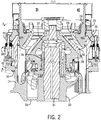
- Fig. 1 illustrates a gyrational crusher, such as a cone crusher 10, that is operable to crush material, such as rock, stone, ore, mineral or other substances.
- the cone crusher 10 shown in Fig. 1 is of sufficiently large size such that the mainframe 12 is split into two separate pieces based upon both manufacturing and transportation limitations.
- the mainframe 12 includes a lower mainframe 14 and an upper mainframe 16 that are joined to each other by a series of fasteners 18.
- the upper mainframe 16 receives and supports an adjustment ring 20.
- a series of pins 22 are used to align the adjustment ring 20 relative to the upper mainframe 16 and prevent rotation there between.
- the adjustment ring 20 receives and partially supports a bowl 24 which in turn supports a bowl liner 26.
- the bowl liner 26 combines with a mantle 28 to define a crushing gap 30.
- Mantle 28 is mounted to a head assembly 32 that is supported on a main shaft 34.
- the main shaft 34 is connected to a mainframe hub 33 that is connected to the outer barrel (cylinder) of the mainframe by multiple arms 35.
- An eccentric 36 rotates about the stationary main shaft 34, thereby causing the head assembly 32 to gyrate within the cone crusher 10. Gyration of the head assembly 32 within the stationary bowl 24 supported by the adjustment ring 20 allows rock, stone, ore, minerals or other materials to be crushed between the mantle 28 and the bowl liner 26.
- a drive shaft rotates the eccentric 36. Since the outer diameter of the eccentric 36 is offset from the inner diameter, the rotation of the eccentric 36 creates the gyrational movement of the head assembly within the stationary bowl 24. The gyrational movement of the head assembly 32 changes the size of the crushing gap 30 which allows the material to be crushed to enter into the crushing gap. Further rotation of the eccentric 36 creates the crushing force within the crushing gap 30 to reduce the size of particles being crushed by the cone crusher 10.
- the cone crusher 10 may be one of many different types of cone crushers available from various manufacturers, such as Metso Minerals of Waukesha, Wisconsin.
- An example of the cone crusher 10 shown in Fig. 1 can be an MP® Series rock crusher, such as the MP 2500 available from Metso Minerals. However, different types of cone crushers could be utilized while operating within the scope of the present disclosure.
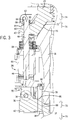
- a series of tramp release cylinders 38 are connected between an attachment flange 40 formed on the adjustment ring 20 and an upper flange 42 formed as part of the lower mainframe 14.
- Each of the tramp release cylinders 38 receives a supply of hydraulic fluid which causes the tramp release cylinder to compress the upper mainframe 16 between the adjustment ring 20 and the lower mainframe 14.
- each of the tramp release cylinders 38 is a double acting hydraulic cylinder that includes a main body 44 that surrounds a movable piston 46. Piston 46 is connected to a piston rod 48. A first end 50 of each tramp release cylinder 38 includes an attachment bracket 52 that receives a connector pin 54. The connector pin 54 extends through a clevis 56 formed as part of the upper flange 42 formed on the lower mainframe 14.
- Second end 58 of the tramp release cylinder 38 is coupled to the attachment flange 40 formed as part of the adjustment ring 20.
- the rod 48 extends through an opening 60 formed in the attachment flange 40.
- the outermost end 62 of the rod includes a spherical nut 64.
- the spherical nut 64 includes a contact surface 66 that is received within a stationary cup 68 that is aligned with the opening 60. The interaction between the spherical nut 64 and the cup 68 allows for a small amount of movement of the rod 48 within the opening 60.
- the piston 46 When hydraulic fluid is supplied to the tramp release cylinder 38, the piston 46 is urged downwardly, which creates the compressive force on the upper mainframe 16.
- the compressive force is seen at the joint created by tapered upper surface 70 on the upper mainframe 16 and the tapered lower surface 72 formed on the adjustment ring 20.
- the compressive force created by the tramp release cylinders 38 is also seen at the joint between the upper mainframe 16 and the lower mainframe 14, such that the upper mainframe 16 is compressed between the adjustment ring 20 and the lower mainframe 14.
- the compressive force created by the tramp release cylinders 38 is shown by arrows 74 in Fig. 3 .
- the hydraulic system allows the oil to flow away from the clamping side of the cylinder when actuated acting to limit hydraulic pressure, allowing the cylinder to have a force limit.
- a series of individual clevises 56 are integrally cast as a portion of the upper attachment flange 42.
- the connector pin 54 passes through conventional attachment bracket 52 that is mounted to the first end of the tramp release cylinder 38. This design allows for the use of a conventional double acting hydraulic cylinder which can be easily connected to the individual clevises 56 through the connector pin 54.
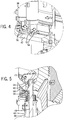
- Fig. 5 illustrates the position of the spherical nut 64 along the rod 48.
- the spherical nut 64 is seated within the cup 68 which rests within a recess formed in the outer surface 73 of the attachment flange 40.
- the recess is defined by a recessed surface 94. The interaction between the spherical nut 64 and the cup 68 allows for slight movement between the two components during the compressive action of the tramp release cylinder 38.
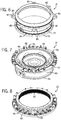
- Fig. 6 illustrates the upper mainframe 16 constructed in accordance with the present disclosure.
- the upper mainframe 16 includes a lower attachment lip 76 that extends radially from a cylindrical main body 77.
- the attachment lip 76 includes a series of holes 78 that receive the fasteners 18 used to secure the upper mainframe 16 to the lower mainframe 14, as illustrated in Fig. 3 .
- the upper end of the upper mainframe 16 includes a series of spaced attachment projections 80 that each include an opening 82.
- the opening 82 receives one of the pins 22 shown in Fig. 1 to constrain in rotation the upper mainframe 16 to the adjustment ring 20. As illustrated in Fig.
- each of the attachment projections 80 is spaced from the adjacent attachment projection 80 by a recessed area 84.
- the recessed area 84 allows the series of tramp release cylinders 38 to extend between the lower mainframe 14 and the adjustment ring 20, as illustrated in Fig. 1 . In this manner, each of the tramp release cylinders 38 does not directly engage the upper mainframe 16 and instead is used to couple the lower mainframe 14 to the adjustment ring 20.
- the lower mainframe 14 includes the series of clevises 56 spaced along the upper flange 42.
- the upper flange 42 extends radially from the cylindrical main body 83 and is spaced vertically above the lower lip 85.
- the position of the individual clevises 56 on the upper flange 42 reduce the overall required length of the tramp release cylinders 38, as compared to an embodiment in which the flange were formed as part of the lower lip 85.
- the lower mainframe 14 includes a flat contact surface 86 that extends axially above the upper flange 42 and includes a series of spaced holes 88.
- Spaced holes 88 have the same spacing as the holes 78 formed on the attachment lip 76 of the upper mainframe 16 such that the fasteners 18 can pass through the aligned holes 78, 88, as shown in Fig. 3 .
- a locking nut 90 holds the fastener 18 in place as illustrated.
- Fig. 8 illustrates the adjustment ring 20 of the present disclosure.
- the adjustment ring 20 includes a threaded inner surface 92 that interacts with the bowl 24 such that the position of the bowl can be adjusted.
- the adjustment ring 20 includes the series of openings 60 formed in the attachment flange 40. Each of the openings 60 extend through the attachment flange 40.
- the openings 60 that support the second end of one of the tramp release cylinders 38 include a counterbore on top.
- the openings 60 that receive one of the pins 22 have a longer counterbore from the bottom to interface with the pin 22.
- the pins 22 are used to circumferentially constrain the adjustment ring 20 to the upper mainframe, as illustrated in Fig. 1 .
- Each of the openings 60 designed to receive the first end of one of the tramp release cylinders 38 includes a recessed surface 94 that serves as the support for the cup 68, as illustrated in Fig. 3 .
- the upper flange 42 of the lower mainframe 14 includes a series of clevises 56 that are spaced around the upper flange 42 and protrude vertically from an upper surface 96 of the upper flange 42.
- each of the clevises 56 is cast as part of the entire lower mainframe and thus is an integral component with the material that forms the upper flange 42.
- Fig. 9 illustrates the integral formation of the clevis 56 with the upper flange 42.
- the clevis 56 includes attachment opening 98 that receives the pivot pin used to connect the tramp release cylinder to the upper flange 42.
- the clevis 56 is spaced radially outward from the holes 88 extending through the contact surface 86 formed on the lower mainframe 14.
- Fig. 10 illustrates an alternate embodiment of clevis 56.
- the clevis 56 is formed as a separate structure that is attached to the upper surface 96 of the upper flange 42.
- the clevis 56 is attached by a pair of fasteners 100.
- the clevis 56 could be attached using other methods, such as welding.
- each of the fasteners 100 passes through an attachment hole 102 formed in a lower support flange 104.
- a threaded portion 106 of the fastener is received in the attachment flange 42 to securely hold the clevis 56 in the position shown in Fig. 10 .
- the lower mainframe 14 can be formed without the clevises 56 and the clevises 56 can be attached in a subsequent attachment process.
- the clevis has been shown and described as being the point of attachment to the upper flange 42 of the lower mainframe 14, it is contemplated that the clevis could be eliminated from the lower mainframe 14 and a portion of the tramp release cylinder could be connected directly to the attachment flange 42, as illustrated in Fig. 11 .
- the clevis is replaced by a series of cylinder attachment openings 108.
- the cylinder attachment openings 108 are spaced around the upper flange 42 at the same spacing as the spacing between the clevises.
- Each of the cylinder attachment openings 108 extends through the entire thickness of the upper attachment flange 42 from the upper surface 96 to lower surface 110.
- FIG. 11 illustrates an embodiment in which the tramp release cylinder 38 shown in Fig. 3 is inverted.
- the first end 50 of the tramp release cylinder 38 will be connected to the attachment flange 40 of the adjustment ring 20 while the second end 58 of the tramp release cylinder 38 is connected to the upper flange 42.
- the attachment flange 40 could include spaced clevises to provide a point of attachment for the tramp release cylinder 38.
- piston rod 48 extends through the cylinder attachment opening 108.
- the piston rod 48 includes a spherical nut 114 that is received within a cup 116.
- the embodiment shown in Fig. 11 eliminates the need for any of the clevises, whether the clevises are integrally formed with the lower mainframe as shown in Fig. 9 or attached at a later processing step, as in the embodiment of Fig. 10 .
- Fig. 12 illustrates yet another alternate embodiment for positioning a series of spaced clevises 56 along the lower mainframe 14.
- the upper flange is reduced and instead a bolt on ring 118 is utilized.
- the bolt on ring 118 includes a support flange 120 having an attachment opening 122.
- the attachment opening 122 is aligned with the holes 88 formed in the lower mainframe 14.
- the holes 88 are primarily utilized to attach the lower mainframe 14 to the upper mainframe 16.
- several of these holes 88 can be utilized to attach the ring 118 to the lower mainframe 14.
- the ring 118 can be formed separately from the lower mainframe 14 and subsequently attached utilizing a series of fasteners, as described.
- the use of a separate bolt on ring 118 is a modular design that reduces the size of the lower mainframe, which may reduce shipping size and costs for the lower mainframe and the separate ring 118.
- the upper flange 42 formed on the lower mainframe 14 also serves as the mounting location for supporting the lower mainframe 14 on a foundation 124.
- a mounting pad 126 is formed as part of the mainframe and is located between the lower surface 110 of the lower mainframe 14 and a top surface 128 of the foundation 124.
- An attachment bolt 130 extends from the upper surface 96 through the upper flange 42 and the mounting pad 126 and is received within the foundation 124. Since the upper flange 42 extends radially past the lower lip 85, the remaining portions of the lower mainframe 14 can extend below the top surface 128 of the foundation.
- Fig. 14 shows an alternate embodiment in which the mounting pad 126 is formed between the lip 85 and the top surface 128 of the foundation 124.
- Fig. 15 illustrates an embodiment in which the mounting pad 126 is formed along the lower surface 110 of the upper flange 42 and is positioned above the top surface 128 of the foundation 124.
- An isolation spring element 134 is schematically illustrated in Fig. 15 .
- the vibration isolation spring 134 is positioned between the foundation and the lower mainframe mounting pad 132 to reduce the transmitted forces from the cone crusher to the foundation.
- the mounting location between the lower mainframe 14 and the foundation 124 is closer to the center of gravity for the cone crusher assembly as compared to the embodiment shown in Fig. 14 .
Landscapes
- Engineering & Computer Science (AREA)
- Food Science & Technology (AREA)
- Mechanical Engineering (AREA)
- Crushing And Grinding (AREA)
- Crushing And Pulverization Processes (AREA)
- Disintegrating Or Milling (AREA)
Applications Claiming Priority (2)
| Application Number | Priority Date | Filing Date | Title |
|---|---|---|---|
| US14/134,625 US20150174581A1 (en) | 2013-12-19 | 2013-12-19 | Split mainframe including tramp release cylinders |
| PCT/US2014/066396 WO2015094556A1 (en) | 2013-12-19 | 2014-11-19 | Split mainframe including tramp release cylinders |
Publications (2)
| Publication Number | Publication Date |
|---|---|
| EP3083060A1 EP3083060A1 (en) | 2016-10-26 |
| EP3083060B1 true EP3083060B1 (en) | 2017-12-20 |
Family
ID=52103003
Family Applications (1)
| Application Number | Title | Priority Date | Filing Date |
|---|---|---|---|
| EP14812680.8A Active EP3083060B1 (en) | 2013-12-19 | 2014-11-19 | Split mainframe including tramp release cylinders |
Country Status (14)
Families Citing this family (5)
| Publication number | Priority date | Publication date | Assignee | Title |
|---|---|---|---|---|
| AU2015401842B2 (en) * | 2015-07-03 | 2018-07-26 | Sandvik Intellectual Property Ab | Crushing shell with rotational lock |
| US10722895B2 (en) * | 2017-04-17 | 2020-07-28 | McCloskey International Limited | Cone crusher |
| CN108160173B (zh) * | 2017-12-28 | 2023-12-22 | 浙江双金机械集团股份有限公司 | 大型移动式石料破碎模块设备 |
| CN108246398A (zh) * | 2017-12-29 | 2018-07-06 | 福建省宝山机械有限公司 | 一种上锥减震的圆锥破碎机 |
| CN108246399A (zh) * | 2017-12-29 | 2018-07-06 | 福建省宝山机械有限公司 | 一种上锥减震摆动式的圆锥破碎机 |
Family Cites Families (36)
| Publication number | Priority date | Publication date | Assignee | Title |
|---|---|---|---|---|
| US557216A (en) * | 1896-03-31 | Stone-breaker | ||
| US500597A (en) * | 1893-07-04 | Crushing-machine | ||
| US348758A (en) * | 1886-09-07 | Crushing-machine | ||
| US1090216A (en) * | 1907-08-05 | 1914-03-17 | Joseph E Kennedy | Crushing and pulverizing machine. |
| US1054135A (en) * | 1908-08-28 | 1913-02-25 | Power And Mining Machinery Company | Crusher. |
| US1799477A (en) * | 1924-12-22 | 1931-04-07 | Allis Chalmers Mfg Co | Crusher |
| US1791584A (en) * | 1929-12-09 | 1931-02-10 | Nordberg Manufacturing Co | Cone crusher |
| US2050718A (en) * | 1935-04-16 | 1936-08-11 | William M Mccaskell | Gyratory crusher |
| US2628788A (en) * | 1946-12-30 | 1953-02-17 | John R Kueneman | Gyratory crusher |
| US3420457A (en) * | 1966-02-10 | 1969-01-07 | Nordberg Manufacturing Co | Locking and adjusting means for crushers and control means therefor |
| US4168036A (en) * | 1978-02-22 | 1979-09-18 | Litton Systems, Inc. | Fabricated cone crusher |
| SU820881A1 (ru) * | 1979-01-15 | 1981-04-15 | Всесоюзный Ордена Трудового Красногознамени Научно-Исследовательскийи Проектный Институт Механическойобработки Полезных Ископаемых | Конусна дробилка |
| US4478373A (en) * | 1980-10-14 | 1984-10-23 | Rexnord Inc. | Conical crusher |
| US5464165A (en) * | 1994-02-07 | 1995-11-07 | W. S. Tyler, Incorporated | Cone crusher having inclined hold-down cylinders |
| US5540394A (en) * | 1995-05-02 | 1996-07-30 | Astec Industries, Inc. | Adjuster mechanism for gyrasphere crusher concave |
| US5927623A (en) * | 1996-03-18 | 1999-07-27 | Cedarapids, Inc. | Gyratory crusher with automatic control system |
| US5738288A (en) * | 1996-06-05 | 1998-04-14 | Nordberg Incorporated | Conical crusher having a single piece inner crushing member |
| US5820045A (en) * | 1996-06-05 | 1998-10-13 | Nordberg Incorporated | Conical Crusher having a single piece outer crushing member |
| US5996916A (en) * | 1996-10-15 | 1999-12-07 | Cedarapids, Inc. | Cone crusher having positive head hold-down mechanism |
| US5806772A (en) * | 1996-11-22 | 1998-09-15 | Nordberg, Inc. | Conical gyratory grinding and crushing apparatus |
| US5931394A (en) * | 1998-03-30 | 1999-08-03 | Astec Industries, Inc. | Anti-spin mechanism for gyratory crusher |
| US5950939A (en) * | 1998-08-24 | 1999-09-14 | Johnson Crushers International | Cone crusher for rock |
| US6000648A (en) * | 1998-10-14 | 1999-12-14 | Ani Mineral Processing, Inc. | Cone crusher having integral socket and main frame |
| US6007009A (en) * | 1998-10-14 | 1999-12-28 | Ani Mineral Processing, Inc. | Bowl assembly for cone crusher |
| US6032886A (en) * | 1999-03-18 | 2000-03-07 | Johnson Crushers International | Adjustment for rock crusher |
| US6513738B1 (en) * | 2000-02-17 | 2003-02-04 | Metso Minerals Industries, Inc. | Adjustment mechanism utilizing a variable displacement motor for a rock crusher |
| CN2619716Y (zh) * | 2003-06-27 | 2004-06-09 | 沈阳工业学院 | 一种圆锥破碎机 |
| US20050269436A1 (en) * | 2004-06-04 | 2005-12-08 | Innotech Solutions, Llc | Cone rock crusher |
| US7104482B2 (en) * | 2004-11-15 | 2006-09-12 | Johnson Crushers International | Clutch for rock crusher |
| FR2879480B1 (fr) * | 2004-12-17 | 2007-03-02 | Metso Minerals France Sa Sa | Broyeur a cone |
| US7566018B1 (en) * | 2008-11-04 | 2009-07-28 | Fl Smidth A/S | Rock crusher counterweight oil deflection plates |
| CN201431893Y (zh) * | 2009-06-29 | 2010-03-31 | 海盐县通惠地质矿山机械有限公司 | 氮气式液压圆锥破碎机的液压清腔、保护和破碎装置 |
| US8387905B2 (en) * | 2010-10-19 | 2013-03-05 | Flsmidth A/S | Modular shell for crusher device |
| KR101191267B1 (ko) * | 2011-04-14 | 2012-10-16 | 하용간 | 콘형 크러셔 |
| KR20120001360U (ko) * | 2011-05-24 | 2012-02-28 | 정태현 | 콘크러셔 |
| CN102357371B (zh) * | 2011-10-02 | 2013-07-31 | 长兴县长虹路桥矿山机械设备有限公司 | 一种多缸液压滚动轴承圆锥破碎机 |
-
2013
- 2013-12-19 US US14/134,625 patent/US20150174581A1/en not_active Abandoned
-
2014
- 2014-11-19 RU RU2016129156A patent/RU2654732C1/ru active
- 2014-11-19 CA CA2934452A patent/CA2934452C/en active Active
- 2014-11-19 MX MX2016008003A patent/MX2016008003A/es active IP Right Grant
- 2014-11-19 PE PE2016000835A patent/PE20160970A1/es unknown
- 2014-11-19 AP AP2016009289A patent/AP2016009289A0/en unknown
- 2014-11-19 WO PCT/US2014/066396 patent/WO2015094556A1/en not_active Ceased
- 2014-11-19 BR BR112016014231A patent/BR112016014231B8/pt active IP Right Grant
- 2014-11-19 ES ES14812680.8T patent/ES2662603T3/es active Active
- 2014-11-19 UA UAA201607882A patent/UA120263C2/uk unknown
- 2014-11-19 CN CN201480069588.4A patent/CN105828951B/zh active Active
- 2014-11-19 EP EP14812680.8A patent/EP3083060B1/en active Active
- 2014-11-19 AU AU2014367110A patent/AU2014367110B2/en active Active
-
2016
- 2016-06-17 CL CL2016001577A patent/CL2016001577A1/es unknown
Also Published As
| Publication number | Publication date |
|---|---|
| PE20160970A1 (es) | 2016-10-08 |
| CA2934452A1 (en) | 2015-06-25 |
| BR112016014231B1 (pt) | 2021-09-28 |
| AP2016009289A0 (en) | 2016-06-30 |
| BR112016014231A2 (cg-RX-API-DMAC7.html) | 2017-08-08 |
| RU2016129156A (ru) | 2018-01-24 |
| RU2654732C1 (ru) | 2018-05-22 |
| MX2016008003A (es) | 2017-03-10 |
| AU2014367110A1 (en) | 2016-07-07 |
| AU2014367110B2 (en) | 2018-08-23 |
| ES2662603T3 (es) | 2018-04-09 |
| BR112016014231B8 (pt) | 2023-03-07 |
| CL2016001577A1 (es) | 2016-11-18 |
| UA120263C2 (uk) | 2019-11-11 |
| CA2934452C (en) | 2021-01-26 |
| EP3083060A1 (en) | 2016-10-26 |
| US20150174581A1 (en) | 2015-06-25 |
| CN105828951A (zh) | 2016-08-03 |
| WO2015094556A1 (en) | 2015-06-25 |
| CN105828951B (zh) | 2018-11-20 |
Similar Documents
| Publication | Publication Date | Title |
|---|---|---|
| EP3083060B1 (en) | Split mainframe including tramp release cylinders | |
| CA2703440C (en) | Concentrated bi-density eccentric counterweight for cone-type rock crusher | |
| CA2774950C (en) | Crusher device | |
| FI128712B (en) | Vertical split bowl liner for cone crusher and cone crusher | |
| US8979009B2 (en) | Concrete crusher | |
| EP3184174A1 (en) | Gyration-type crusher | |
| EP2716365B1 (en) | Gyratory crusher bearing | |
| EP3184173A1 (en) | Gyration-type crusher | |
| AU2015303921A1 (en) | Top service clamping cylinders for a gyratory crusher | |
| AU2014379504B2 (en) | System and method for hydraulically removing a socket from a mainshaft of a gyrational crusher |
Legal Events
| Date | Code | Title | Description |
|---|---|---|---|
| PUAI | Public reference made under article 153(3) epc to a published international application that has entered the european phase |
Free format text: ORIGINAL CODE: 0009012 |
|
| 17P | Request for examination filed |
Effective date: 20160615 |
|
| AK | Designated contracting states |
Kind code of ref document: A1 Designated state(s): AL AT BE BG CH CY CZ DE DK EE ES FI FR GB GR HR HU IE IS IT LI LT LU LV MC MK MT NL NO PL PT RO RS SE SI SK SM TR |
|
| AX | Request for extension of the european patent |
Extension state: BA ME |
|
| DAX | Request for extension of the european patent (deleted) | ||
| GRAP | Despatch of communication of intention to grant a patent |
Free format text: ORIGINAL CODE: EPIDOSNIGR1 |
|
| STAA | Information on the status of an ep patent application or granted ep patent |
Free format text: STATUS: GRANT OF PATENT IS INTENDED |
|
| INTG | Intention to grant announced |
Effective date: 20170626 |
|
| GRAS | Grant fee paid |
Free format text: ORIGINAL CODE: EPIDOSNIGR3 |
|
| GRAA | (expected) grant |
Free format text: ORIGINAL CODE: 0009210 |
|
| STAA | Information on the status of an ep patent application or granted ep patent |
Free format text: STATUS: THE PATENT HAS BEEN GRANTED |
|
| AK | Designated contracting states |
Kind code of ref document: B1 Designated state(s): AL AT BE BG CH CY CZ DE DK EE ES FI FR GB GR HR HU IE IS IT LI LT LU LV MC MK MT NL NO PL PT RO RS SE SI SK SM TR |
|
| REG | Reference to a national code |
Ref country code: GB Ref legal event code: FG4D |
|
| REG | Reference to a national code |
Ref country code: CH Ref legal event code: EP |
|
| REG | Reference to a national code |
Ref country code: IE Ref legal event code: FG4D |
|
| REG | Reference to a national code |
Ref country code: AT Ref legal event code: REF Ref document number: 955887 Country of ref document: AT Kind code of ref document: T Effective date: 20180115 |
|
| REG | Reference to a national code |
Ref country code: DE Ref legal event code: R096 Ref document number: 602014018914 Country of ref document: DE |
|
| REG | Reference to a national code |
Ref country code: ES Ref legal event code: FG2A Ref document number: 2662603 Country of ref document: ES Kind code of ref document: T3 Effective date: 20180409 |
|
| REG | Reference to a national code |
Ref country code: SE Ref legal event code: TRGR |
|
| REG | Reference to a national code |
Ref country code: NL Ref legal event code: MP Effective date: 20171220 |
|
| PG25 | Lapsed in a contracting state [announced via postgrant information from national office to epo] |
Ref country code: LT Free format text: LAPSE BECAUSE OF FAILURE TO SUBMIT A TRANSLATION OF THE DESCRIPTION OR TO PAY THE FEE WITHIN THE PRESCRIBED TIME-LIMIT Effective date: 20171220 Ref country code: NO Free format text: LAPSE BECAUSE OF FAILURE TO SUBMIT A TRANSLATION OF THE DESCRIPTION OR TO PAY THE FEE WITHIN THE PRESCRIBED TIME-LIMIT Effective date: 20180320 |
|
| REG | Reference to a national code |
Ref country code: LT Ref legal event code: MG4D |
|
| REG | Reference to a national code |
Ref country code: AT Ref legal event code: MK05 Ref document number: 955887 Country of ref document: AT Kind code of ref document: T Effective date: 20171220 |
|
| PG25 | Lapsed in a contracting state [announced via postgrant information from national office to epo] |
Ref country code: GR Free format text: LAPSE BECAUSE OF FAILURE TO SUBMIT A TRANSLATION OF THE DESCRIPTION OR TO PAY THE FEE WITHIN THE PRESCRIBED TIME-LIMIT Effective date: 20180321 Ref country code: LV Free format text: LAPSE BECAUSE OF FAILURE TO SUBMIT A TRANSLATION OF THE DESCRIPTION OR TO PAY THE FEE WITHIN THE PRESCRIBED TIME-LIMIT Effective date: 20171220 Ref country code: RS Free format text: LAPSE BECAUSE OF FAILURE TO SUBMIT A TRANSLATION OF THE DESCRIPTION OR TO PAY THE FEE WITHIN THE PRESCRIBED TIME-LIMIT Effective date: 20171220 Ref country code: BG Free format text: LAPSE BECAUSE OF FAILURE TO SUBMIT A TRANSLATION OF THE DESCRIPTION OR TO PAY THE FEE WITHIN THE PRESCRIBED TIME-LIMIT Effective date: 20180320 Ref country code: HR Free format text: LAPSE BECAUSE OF FAILURE TO SUBMIT A TRANSLATION OF THE DESCRIPTION OR TO PAY THE FEE WITHIN THE PRESCRIBED TIME-LIMIT Effective date: 20171220 |
|
| PG25 | Lapsed in a contracting state [announced via postgrant information from national office to epo] |
Ref country code: NL Free format text: LAPSE BECAUSE OF FAILURE TO SUBMIT A TRANSLATION OF THE DESCRIPTION OR TO PAY THE FEE WITHIN THE PRESCRIBED TIME-LIMIT Effective date: 20171220 |
|
| PG25 | Lapsed in a contracting state [announced via postgrant information from national office to epo] |
Ref country code: SK Free format text: LAPSE BECAUSE OF FAILURE TO SUBMIT A TRANSLATION OF THE DESCRIPTION OR TO PAY THE FEE WITHIN THE PRESCRIBED TIME-LIMIT Effective date: 20171220 Ref country code: EE Free format text: LAPSE BECAUSE OF FAILURE TO SUBMIT A TRANSLATION OF THE DESCRIPTION OR TO PAY THE FEE WITHIN THE PRESCRIBED TIME-LIMIT Effective date: 20171220 Ref country code: CY Free format text: LAPSE BECAUSE OF FAILURE TO SUBMIT A TRANSLATION OF THE DESCRIPTION OR TO PAY THE FEE WITHIN THE PRESCRIBED TIME-LIMIT Effective date: 20171220 Ref country code: CZ Free format text: LAPSE BECAUSE OF FAILURE TO SUBMIT A TRANSLATION OF THE DESCRIPTION OR TO PAY THE FEE WITHIN THE PRESCRIBED TIME-LIMIT Effective date: 20171220 |
|
| PG25 | Lapsed in a contracting state [announced via postgrant information from national office to epo] |
Ref country code: IT Free format text: LAPSE BECAUSE OF FAILURE TO SUBMIT A TRANSLATION OF THE DESCRIPTION OR TO PAY THE FEE WITHIN THE PRESCRIBED TIME-LIMIT Effective date: 20171220 Ref country code: SM Free format text: LAPSE BECAUSE OF FAILURE TO SUBMIT A TRANSLATION OF THE DESCRIPTION OR TO PAY THE FEE WITHIN THE PRESCRIBED TIME-LIMIT Effective date: 20171220 Ref country code: PL Free format text: LAPSE BECAUSE OF FAILURE TO SUBMIT A TRANSLATION OF THE DESCRIPTION OR TO PAY THE FEE WITHIN THE PRESCRIBED TIME-LIMIT Effective date: 20171220 Ref country code: AT Free format text: LAPSE BECAUSE OF FAILURE TO SUBMIT A TRANSLATION OF THE DESCRIPTION OR TO PAY THE FEE WITHIN THE PRESCRIBED TIME-LIMIT Effective date: 20171220 Ref country code: IS Free format text: LAPSE BECAUSE OF FAILURE TO SUBMIT A TRANSLATION OF THE DESCRIPTION OR TO PAY THE FEE WITHIN THE PRESCRIBED TIME-LIMIT Effective date: 20180420 |
|
| REG | Reference to a national code |
Ref country code: DE Ref legal event code: R097 Ref document number: 602014018914 Country of ref document: DE |
|
| REG | Reference to a national code |
Ref country code: FR Ref legal event code: PLFP Year of fee payment: 5 |
|
| PLBE | No opposition filed within time limit |
Free format text: ORIGINAL CODE: 0009261 |
|
| STAA | Information on the status of an ep patent application or granted ep patent |
Free format text: STATUS: NO OPPOSITION FILED WITHIN TIME LIMIT |
|
| PG25 | Lapsed in a contracting state [announced via postgrant information from national office to epo] |
Ref country code: DK Free format text: LAPSE BECAUSE OF FAILURE TO SUBMIT A TRANSLATION OF THE DESCRIPTION OR TO PAY THE FEE WITHIN THE PRESCRIBED TIME-LIMIT Effective date: 20171220 |
|
| 26N | No opposition filed |
Effective date: 20180921 |
|
| PG25 | Lapsed in a contracting state [announced via postgrant information from national office to epo] |
Ref country code: SI Free format text: LAPSE BECAUSE OF FAILURE TO SUBMIT A TRANSLATION OF THE DESCRIPTION OR TO PAY THE FEE WITHIN THE PRESCRIBED TIME-LIMIT Effective date: 20171220 |
|
| REG | Reference to a national code |
Ref country code: CH Ref legal event code: PL |
|
| PG25 | Lapsed in a contracting state [announced via postgrant information from national office to epo] |
Ref country code: LU Free format text: LAPSE BECAUSE OF NON-PAYMENT OF DUE FEES Effective date: 20181119 Ref country code: MC Free format text: LAPSE BECAUSE OF FAILURE TO SUBMIT A TRANSLATION OF THE DESCRIPTION OR TO PAY THE FEE WITHIN THE PRESCRIBED TIME-LIMIT Effective date: 20171220 |
|
| REG | Reference to a national code |
Ref country code: IE Ref legal event code: MM4A |
|
| PG25 | Lapsed in a contracting state [announced via postgrant information from national office to epo] |
Ref country code: CH Free format text: LAPSE BECAUSE OF NON-PAYMENT OF DUE FEES Effective date: 20181130 Ref country code: LI Free format text: LAPSE BECAUSE OF NON-PAYMENT OF DUE FEES Effective date: 20181130 |
|
| PG25 | Lapsed in a contracting state [announced via postgrant information from national office to epo] |
Ref country code: IE Free format text: LAPSE BECAUSE OF NON-PAYMENT OF DUE FEES Effective date: 20181119 |
|
| PG25 | Lapsed in a contracting state [announced via postgrant information from national office to epo] |
Ref country code: MT Free format text: LAPSE BECAUSE OF NON-PAYMENT OF DUE FEES Effective date: 20181119 |
|
| PG25 | Lapsed in a contracting state [announced via postgrant information from national office to epo] |
Ref country code: PT Free format text: LAPSE BECAUSE OF FAILURE TO SUBMIT A TRANSLATION OF THE DESCRIPTION OR TO PAY THE FEE WITHIN THE PRESCRIBED TIME-LIMIT Effective date: 20171220 |
|
| PG25 | Lapsed in a contracting state [announced via postgrant information from national office to epo] |
Ref country code: RO Free format text: LAPSE BECAUSE OF FAILURE TO SUBMIT A TRANSLATION OF THE DESCRIPTION OR TO PAY THE FEE WITHIN THE PRESCRIBED TIME-LIMIT Effective date: 20171220 Ref country code: MK Free format text: LAPSE BECAUSE OF NON-PAYMENT OF DUE FEES Effective date: 20171220 Ref country code: HU Free format text: LAPSE BECAUSE OF FAILURE TO SUBMIT A TRANSLATION OF THE DESCRIPTION OR TO PAY THE FEE WITHIN THE PRESCRIBED TIME-LIMIT; INVALID AB INITIO Effective date: 20141119 |
|
| PG25 | Lapsed in a contracting state [announced via postgrant information from national office to epo] |
Ref country code: AL Free format text: LAPSE BECAUSE OF FAILURE TO SUBMIT A TRANSLATION OF THE DESCRIPTION OR TO PAY THE FEE WITHIN THE PRESCRIBED TIME-LIMIT Effective date: 20171220 |
|
| REG | Reference to a national code |
Ref country code: ES Ref legal event code: PC2A Owner name: METSO OUTOTEC USA INC Effective date: 20221018 |
|
| REG | Reference to a national code |
Ref country code: BE Ref legal event code: PD Owner name: METSO OUTOTEC USA INC.; US Free format text: DETAILS ASSIGNMENT: CHANGE OF OWNER(S), MERGE; FORMER OWNER NAME: METSO MINERALS INDUSTRIES, INC. Effective date: 20221019 |
|
| REG | Reference to a national code |
Ref country code: GB Ref legal event code: 732E Free format text: REGISTERED BETWEEN 20230202 AND 20230208 |
|
| REG | Reference to a national code |
Ref country code: DE Ref legal event code: R081 Ref document number: 602014018914 Country of ref document: DE Owner name: METSO OUTOTEC USA INC., BROOKFIELD, US Free format text: FORMER OWNER: METSO MINERALS INDUSTRIES, INC., WAUKESHA, WIS., US Ref country code: DE Ref legal event code: R081 Ref document number: 602014018914 Country of ref document: DE Owner name: METSO USA INC. (N.D.GES.D.STAATES DELAWARE), B, US Free format text: FORMER OWNER: METSO MINERALS INDUSTRIES, INC., WAUKESHA, WIS., US |
|
| P01 | Opt-out of the competence of the unified patent court (upc) registered |
Effective date: 20230527 |
|
| REG | Reference to a national code |
Ref country code: FI Ref legal event code: PCE Owner name: METSO OUTOTEC USA INC., US |
|
| REG | Reference to a national code |
Ref country code: DE Ref legal event code: R081 Ref document number: 602014018914 Country of ref document: DE Owner name: METSO USA INC. (N.D.GES.D.STAATES DELAWARE), B, US Free format text: FORMER OWNER: METSO OUTOTEC USA INC., BROOKFIELD, WI, US |
|
| REG | Reference to a national code |
Ref country code: BE Ref legal event code: HC Owner name: METSO USA INC.; US Free format text: DETAILS ASSIGNMENT: CHANGE OF OWNER(S), CHANGE OF OWNER(S) NAME; FORMER OWNER NAME: METSO OUTOTEC USA INC. Effective date: 20250624 |
|
| REG | Reference to a national code |
Ref country code: ES Ref legal event code: PC2A Owner name: METSO USA INC. Effective date: 20251128 |
|
| PGFP | Annual fee paid to national office [announced via postgrant information from national office to epo] |
Ref country code: DE Payment date: 20251007 Year of fee payment: 12 |
|
| PGFP | Annual fee paid to national office [announced via postgrant information from national office to epo] |
Ref country code: GB Payment date: 20251016 Year of fee payment: 12 |
|
| PGFP | Annual fee paid to national office [announced via postgrant information from national office to epo] |
Ref country code: FI Payment date: 20251113 Year of fee payment: 12 |
|
| PGFP | Annual fee paid to national office [announced via postgrant information from national office to epo] |
Ref country code: FR Payment date: 20251023 Year of fee payment: 12 |
|
| PGFP | Annual fee paid to national office [announced via postgrant information from national office to epo] |
Ref country code: TR Payment date: 20251106 Year of fee payment: 12 Ref country code: BE Payment date: 20251015 Year of fee payment: 12 |
|
| PGFP | Annual fee paid to national office [announced via postgrant information from national office to epo] |
Ref country code: SE Payment date: 20251010 Year of fee payment: 12 |
|
| PGFP | Annual fee paid to national office [announced via postgrant information from national office to epo] |
Ref country code: ES Payment date: 20251210 Year of fee payment: 12 |