EP3081688A2 - Electrical household appliance - Google Patents
Electrical household appliance Download PDFInfo
- Publication number
- EP3081688A2 EP3081688A2 EP16169116.7A EP16169116A EP3081688A2 EP 3081688 A2 EP3081688 A2 EP 3081688A2 EP 16169116 A EP16169116 A EP 16169116A EP 3081688 A2 EP3081688 A2 EP 3081688A2
- Authority
- EP
- European Patent Office
- Prior art keywords
- channel
- passage
- fluid
- household appliance
- refrigerant fluid
- Prior art date
- Legal status (The legal status is an assumption and is not a legal conclusion. Google has not performed a legal analysis and makes no representation as to the accuracy of the status listed.)
- Withdrawn
Links
- 239000012530 fluid Substances 0.000 claims abstract description 106
- 239000003507 refrigerant Substances 0.000 claims abstract description 51
- 238000001035 drying Methods 0.000 claims abstract description 28
- 238000000605 extraction Methods 0.000 claims abstract description 6
- 238000009833 condensation Methods 0.000 claims abstract description 4
- 230000005494 condensation Effects 0.000 claims abstract description 4
- 238000005406 washing Methods 0.000 claims description 14
- 238000004891 communication Methods 0.000 claims description 10
- 238000005192 partition Methods 0.000 claims description 10
- 239000007788 liquid Substances 0.000 claims description 6
- 238000004804 winding Methods 0.000 claims description 6
- 229910052751 metal Inorganic materials 0.000 claims description 5
- 239000002184 metal Substances 0.000 claims description 5
- XLYOFNOQVPJJNP-UHFFFAOYSA-N water Substances O XLYOFNOQVPJJNP-UHFFFAOYSA-N 0.000 description 3
- 239000000498 cooling water Substances 0.000 description 2
- 239000000463 material Substances 0.000 description 2
- 238000000034 method Methods 0.000 description 2
- 239000004411 aluminium Substances 0.000 description 1
- 229910052782 aluminium Inorganic materials 0.000 description 1
- XAGFODPZIPBFFR-UHFFFAOYSA-N aluminium Chemical compound [Al] XAGFODPZIPBFFR-UHFFFAOYSA-N 0.000 description 1
- 238000000071 blow moulding Methods 0.000 description 1
- 238000010276 construction Methods 0.000 description 1
- 238000001816 cooling Methods 0.000 description 1
- 239000000284 extract Substances 0.000 description 1
- 238000010438 heat treatment Methods 0.000 description 1
- 238000004519 manufacturing process Methods 0.000 description 1
- 238000000465 moulding Methods 0.000 description 1
- 238000007493 shaping process Methods 0.000 description 1
Images

Classifications
-
- D—TEXTILES; PAPER
- D06—TREATMENT OF TEXTILES OR THE LIKE; LAUNDERING; FLEXIBLE MATERIALS NOT OTHERWISE PROVIDED FOR
- D06F—LAUNDERING, DRYING, IRONING, PRESSING OR FOLDING TEXTILE ARTICLES
- D06F58/00—Domestic laundry dryers
- D06F58/20—General details of domestic laundry dryers
- D06F58/24—Condensing arrangements
Definitions
- This invention relates to an electrical household appliance for drying laundry.
- the electrical household appliance might also be a washer-dryer where the drying action follows a washing action.
- an electrical household drying appliance which comprises a plastic duct extending between a laundry drying compartment and an impeller which extracts moist air from the compartment.
- the duct Along the inside surface of the duct there is a plurality of outlet nozzles for delivering cooling water from the water mains.
- the cooling water sprayed inside the duct condenses part of the moisture present in the air extracted from the drying compartment.
- a drawback of a solution of this type is its low condensing efficiency.
- Document EP 0 429 953 describes a laundry dryer with a condenser having a channel for the passage of hot air from the drying compartment and a channel for the passage of cooling air used as refrigerant fluid, these channels being separated by a condensing wall.
- the technical purpose which forms the basis of this invention is to propose an electrical household appliance that overcomes the above mentioned drawbacks of the prior art.
- the aim of this invention is to provide an electrical household appliance capable of improving the efficiency with which the moisture extracted from the washing compartment is condensed.
- the reference numeral 1 denotes an electrical household appliance for drying laundry.
- electrical household appliances capable of performing this function are known as dryers or washer-dryers (which wash and dry the laundry).
- the electrical household appliance 1 comprises:
- the extraction line 3 is at least partly interposed between the drying compartment 2 and an impeller 5 which sucks the gaseous fluid (typically moist air) from the drying compartment 2. Downstream of the impeller 5, the gaseous fluid is advantageously heated by a heating element and channelled back into the drying compartment 2.
- the electrical household appliance 1 comprises a door 6 giving access to the drying compartment 2 and a wall 60 opposite the door 6, the door 6 and the wall 60 contributing to delimiting the drying compartment 2.
- the extraction line 3 extends from the wall 60 opposite the door 6.
- the extraction line 3 comprises a condenser 4 which allows the condensation of at least a part of the vapour present in the gaseous fluid.
- the condenser 4 is connected directly to at least one of the walls delimiting the drying compartment 2 (typically the wall 60 opposite the door 6).
- the condenser 4 comprises:
- the condenser 4 comprises a condensing wall 40 which separates the channel 41 for the passage of the gaseous fluid from a first part of the channel 42 for the passage of the refrigerant fluid.
- the condensing wall 40 extends for a length greater than 5 centimetres along the line followed by the first part of the channel 42.
- the condensing wall 40 shapes or contributes to shaping the channel 41 for the passage of the gaseous fluid and the first part of the channel 42 for the passage of the refrigerant fluid.
- the condensing wall 40 is in contact with the channel 41 for the passage of the gaseous fluid and the first part of the channel 42 for the passage of the refrigerant fluid.
- the condensing wall 40 usually has a thickness of less than 3 millimetres. It may be made of plastic material (as in the embodiment illustrated in Figure 8 ) or metal (as in the embodiment illustrated in Figure 3 ).
- the first part of the channel 42 for the passage of the refrigerant fluid extends substantially alongside the channel 41 for the passage of the gaseous fluid.
- the refrigerant fluid in the first part of the channel 42 for the passage of the refrigerant fluid flows in the opposite direction to the gaseous fluid in the channel 41 for the passage of the gaseous fluid.
- the first part of the channel 42 for the passage of the refrigerant fluid has a winding shape. This considerably improves heat exchange with the gaseous fluid.
- the condensing wall 40 extends substantially parallel to a plane.
- the condensing wall 40 is planar.
- the first part of the channel 42 for the passage of the refrigerant fluid defines a zone which extends substantially parallel to a plane, this zone being for exchanging heat with the channel 41 for the passage of the gaseous fluid.
- the condenser 4 comprises two superposed metal sheets comprising a first portion where they are in contact and a second portion where they are apart so as to define, interposed between them, the first part of the channel 42 for the passage of the refrigerant fluid.
- the condensing wall 40 is integrated into the two superposed metal sheets.
- the metal sheets are irremovably connected to each other (by a process known as "roll-bonding"). They are preferably made of aluminium.
- the condenser 4 comprises an outer delimiting surface 45.
- the first part of the channel 42 for the passage of the refrigerant fluid conveniently defines a gap 46 interposed between the channel 41 for the passage of the gaseous fluid and the outer delimiting surface 45 of the condenser 4.
- the first part of the channel 42 for the passage of the refrigerant fluid is interposed between the outer delimiting surface 45 and a duct which delimits the channel 41 for the passage of the gaseous fluid; thus, a duct delimiting the first part of the channel 42 does not extend into the channel 41 of the passage of the gaseous fluid.
- the gap 46 is delimited by:
- the gap 46 comprises a plurality of partitions 463 which confer a winding shape on the first part of the channel 42 for the passage of the refrigerant fluid.
- the partitions 463 are at least partly built into the lid 462. More specifically, the partitions 463 extend from a base 465 of the lid 462 until coming into contact with a wall of the shell 461 opposite the base 465 of the lid 462.
- the partitions 463 are transversal (preferably at right angles) to the base 465 of the lid 462. That way, the shell 461 and the lid 462 define, in combination, the channel 42 for the passage of the refrigerant fluid.
- the partitions 463 are formed entirely on the lid 462. In an alternative embodiment, they might be aligned with partitions formed on the shell 461 to define, in combination, the winding channel 42 for the passage of the refrigerant fluid.
- the utility of placing the partitions 463 on the lid is linked to the fact that simplifying the geometry of the shell 461 allows it to be made as a single part, preferably by blow moulding, without abandoning the advantages of a winding path in terms of heat exchange efficiency.
- the partitions 463 are formed (for example, by moulding) on the lid 462. This feature facilitates the process for manufacturing the condenser 4.
- the shell 461 delimits the channel 41 for the passage of the gaseous fluid.
- the gap 46 only partly circumscribes the channel 41 for the passage of the gaseous fluid.
- An extension line followed by the channel 41 for the passage of the gaseous fluid is defined.
- the gap 46 or the channel 42 for the passage of the refrigerant fluid
- the channel 41 comprises two main legs 71, 72 which are transversal to each other (for example, substantially at right angles).
- the channel 42 for the passage of the refrigerant fluid extends only along one of the two main legs.
- the outer delimiting surface 45 comprises:
- the channel 42 for the passage of the refrigerant fluid extends along the first face 73.
- the channel 42 for the passage of the refrigerant fluid does not, on the other hand, extend along the second face 74 and the two flanks 75, 76.
- conduit comprising a part which places the channel 42 for the passage of the refrigerant fluid and the channel 41 for the passage of the gaseous fluid in fluid communication, the part of the conduit being at least partly outside the condenser 4.
- the channel 42 for the passage of the refrigerant fluid comprises a tank 48 comprising an interfacing opening 481 which places it in fluid communication with the channel 41 for the passage of the gaseous fluid.
- the tank 48 is annular and surrounds the channel 41 for the passage of the gaseous fluid.
- the tank 48 comprises an outlet 482 for delivering the refrigerant fluid.
- the opening 481 of the tank defines a spillway through which the refrigerant fluid flows out of the channel for the passage of the gaseous fluid. In this case, the refrigerant fluid is then extracted by the same means as those used for extracting the condensate.
- the tank 48 may comprise a refrigerant fluid extraction outlet 483 separate from the opening 481.
- the condensing wall 40 might coincide with a wall which delimits a tubular duct for the passage of the refrigerant fluid and extending inside a duct which externally delimits the channel 41 for the passage of the gaseous fluid.
- the electrical household appliance 1 is a washer-dryer where the drying compartment 2 coincides with a washing compartment 2.
- the electrical household appliance 1 performs both a washing treatment and a drying treatment.
- the washing compartment 2 houses a rotating drum.
- the washer-dryer comprises washing liquid drainage means (for example a drain pump and pipe) which are, advantageously:
- the electrical household appliance 1, in the embodiment of Figure 8 comprises a condensate outlet channel 47 outside the channel 41 for the passage of the gaseous fluid.
- the outlet channel 47 places the channel 41 for the passage of the gaseous fluid in fluid communication with the washing compartment 2. This allows also the condensate which forms in the condenser 4 to be extracted by way of the drainage means used to extract the washing liquid or the refrigerant fluid.
- the refrigerant fluid might not be in fluid communication with the washing compartment 2. In that case, it is extracted by way of dedicated drainage means (pump, ducting, etc.).
Landscapes
- Engineering & Computer Science (AREA)
- Textile Engineering (AREA)
- Detail Structures Of Washing Machines And Dryers (AREA)
- Surgical Instruments (AREA)
Abstract
i) a drying compartment (2);
ii) a line (3) for extracting a gaseous fluid from the drying compartment (2), the extraction line (3) comprising a condenser (4) which allows the condensation of at least a part of the vapour present in the gaseous fluid.
- a channel (41) for the passage of the gaseous fluid from the drying compartment (2);
- a channel (42) for the passage of a refrigerant fluid.
Description
- This invention relates to an electrical household appliance for drying laundry. The electrical household appliance might also be a washer-dryer where the drying action follows a washing action.
- Known in the prior art is an electrical household drying appliance which comprises a plastic duct extending between a laundry drying compartment and an impeller which extracts moist air from the compartment.
- Along the inside surface of the duct there is a plurality of outlet nozzles for delivering cooling water from the water mains. The cooling water sprayed inside the duct condenses part of the moisture present in the air extracted from the drying compartment.
- A drawback of a solution of this type is its low condensing efficiency.
- Document
EP 0 429 953 describes a laundry dryer with a condenser having a channel for the passage of hot air from the drying compartment and a channel for the passage of cooling air used as refrigerant fluid, these channels being separated by a condensing wall. - In this context, the technical purpose which forms the basis of this invention is to propose an electrical household appliance that overcomes the above mentioned drawbacks of the prior art.
- More specifically, the aim of this invention is to provide an electrical household appliance capable of improving the efficiency with which the moisture extracted from the washing compartment is condensed.
- The technical purpose indicated and the aims specified are substantially achieved by an electrical household appliance comprising the technical features described in one or more of the appended claims.
- Further features and advantages of the invention are more apparent in the non-limiting description which follows of a preferred non-limiting embodiment of an electrical household appliance illustrated in the accompanying drawings, in which:
-
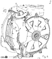
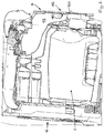
Figure 1 is a perspective view of a component of an electrical household appliance in accordance with this invention; -
Figure 2 shows a cross section ofFigure 1 ; -
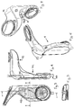
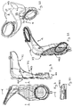
Figure 3 shows a component of an electrical household appliance in accordance with this invention; -
Figure 4 shows a cross section through the plane A-A ofFigure 3 ; -
Figure 5 shows a cross section through the plane B-B ofFigure 3 ; -
Figures 6 and 7 are perspective views of the component ofFigure 3 ; -
Figure 8 shows a component alternative to that ofFigure 3 ; -
Figure 9 shows a cross section through the plane A-A ofFigure 8 ; -
Figure 10 shows a cross section through the plane B-B ofFigure 8 ; -
Figures 11 and 12 are perspective views of the component ofFigure 8 ; -
Figure 13 schematically shows a component alternative to those ofFigures 3 and8 . - In the accompanying drawings, the
reference numeral 1 denotes an electrical household appliance for drying laundry. Typically, electrical household appliances capable of performing this function are known as dryers or washer-dryers (which wash and dry the laundry). - The
electrical household appliance 1 comprises: - i) a
drying compartment 2; - ii) a
line 3 for extracting a gaseous fluid from thedrying compartment 2. - Conveniently, the
extraction line 3 is at least partly interposed between thedrying compartment 2 and animpeller 5 which sucks the gaseous fluid (typically moist air) from thedrying compartment 2. Downstream of theimpeller 5, the gaseous fluid is advantageously heated by a heating element and channelled back into thedrying compartment 2. Conveniently, theelectrical household appliance 1 comprises a door 6 giving access to thedrying compartment 2 and a wall 60 opposite the door 6, the door 6 and the wall 60 contributing to delimiting thedrying compartment 2. Theextraction line 3 extends from the wall 60 opposite the door 6. - The
extraction line 3 comprises acondenser 4 which allows the condensation of at least a part of the vapour present in the gaseous fluid. Conveniently, thecondenser 4 is connected directly to at least one of the walls delimiting the drying compartment 2 (typically the wall 60 opposite the door 6). - The
condenser 4 comprises: - a
channel 41 for the passage of the gaseous fluid from thedrying compartment 2; - a
channel 42 for the passage of a refrigerant fluid. Typically, the refrigerant fluid is liquid, in particular, water (preferably drawn from the water mains). - The
condenser 4 comprises acondensing wall 40 which separates thechannel 41 for the passage of the gaseous fluid from a first part of thechannel 42 for the passage of the refrigerant fluid. Thecondensing wall 40 extends for a length greater than 5 centimetres along the line followed by the first part of thechannel 42. - The
condensing wall 40 shapes or contributes to shaping thechannel 41 for the passage of the gaseous fluid and the first part of thechannel 42 for the passage of the refrigerant fluid. Thus, thecondensing wall 40 is in contact with thechannel 41 for the passage of the gaseous fluid and the first part of thechannel 42 for the passage of the refrigerant fluid. Thecondensing wall 40 usually has a thickness of less than 3 millimetres. It may be made of plastic material (as in the embodiment illustrated inFigure 8 ) or metal (as in the embodiment illustrated inFigure 3 ). - Conveniently, the first part of the
channel 42 for the passage of the refrigerant fluid extends substantially alongside thechannel 41 for the passage of the gaseous fluid. In the preferred embodiment, the refrigerant fluid in the first part of thechannel 42 for the passage of the refrigerant fluid flows in the opposite direction to the gaseous fluid in thechannel 41 for the passage of the gaseous fluid. Conveniently, the first part of thechannel 42 for the passage of the refrigerant fluid has a winding shape. This considerably improves heat exchange with the gaseous fluid. - Conveniently, the
condensing wall 40 extends substantially parallel to a plane. Preferably, thecondensing wall 40 is planar. - In the embodiment of
Figure 3 or8 , the first part of thechannel 42 for the passage of the refrigerant fluid defines a zone which extends substantially parallel to a plane, this zone being for exchanging heat with thechannel 41 for the passage of the gaseous fluid. - In the embodiment of
Figure 3 , thecondenser 4 comprises two superposed metal sheets comprising a first portion where they are in contact and a second portion where they are apart so as to define, interposed between them, the first part of thechannel 42 for the passage of the refrigerant fluid. Thecondensing wall 40 is integrated into the two superposed metal sheets. The metal sheets are irremovably connected to each other (by a process known as "roll-bonding"). They are preferably made of aluminium. - As shown by way of example in the embodiments illustrated, the
condenser 4 comprises an outerdelimiting surface 45. The first part of thechannel 42 for the passage of the refrigerant fluid conveniently defines agap 46 interposed between thechannel 41 for the passage of the gaseous fluid and the outer delimitingsurface 45 of thecondenser 4. Conveniently, the first part of thechannel 42 for the passage of the refrigerant fluid is interposed between the outerdelimiting surface 45 and a duct which delimits thechannel 41 for the passage of the gaseous fluid; thus, a duct delimiting the first part of thechannel 42 does not extend into thechannel 41 of the passage of the gaseous fluid. - In the embodiment of
Figure 8 , thegap 46 is delimited by: - a
shell 461 made as a single part and having an opening; - a
lid 462 which occludes the opening. Conveniently, the outer delimitingsurface 45 is partly integrated into thelid 462. - The
gap 46 comprises a plurality ofpartitions 463 which confer a winding shape on the first part of thechannel 42 for the passage of the refrigerant fluid. Thepartitions 463 are at least partly built into thelid 462. More specifically, thepartitions 463 extend from abase 465 of thelid 462 until coming into contact with a wall of theshell 461 opposite thebase 465 of thelid 462. Thepartitions 463 are transversal (preferably at right angles) to thebase 465 of thelid 462. That way, theshell 461 and thelid 462 define, in combination, thechannel 42 for the passage of the refrigerant fluid. Advantageously, thepartitions 463 are formed entirely on thelid 462. In an alternative embodiment, they might be aligned with partitions formed on theshell 461 to define, in combination, the windingchannel 42 for the passage of the refrigerant fluid. - The utility of placing the
partitions 463 on the lid is linked to the fact that simplifying the geometry of theshell 461 allows it to be made as a single part, preferably by blow moulding, without abandoning the advantages of a winding path in terms of heat exchange efficiency. Conveniently, thepartitions 463 are formed (for example, by moulding) on thelid 462. This feature facilitates the process for manufacturing thecondenser 4. Conveniently, theshell 461 delimits thechannel 41 for the passage of the gaseous fluid. - In the preferred embodiment, the
gap 46 only partly circumscribes thechannel 41 for the passage of the gaseous fluid. An extension line followed by thechannel 41 for the passage of the gaseous fluid is defined. Conveniently, the gap 46 (or thechannel 42 for the passage of the refrigerant fluid) does not completely surround the extension line followed by thechannel 41 for the passage of the gaseous fluid (the Applicant has found that this considerably simplifies construction but without reducing heat exchange efficiency). - Conveniently, the
channel 41 comprises twomain legs channel 42 for the passage of the refrigerant fluid extends only along one of the two main legs. - Conveniently, the outer delimiting
surface 45 comprises: - a first and a
second face - two
flanks - Conveniently, the
channel 42 for the passage of the refrigerant fluid extends along thefirst face 73. Thechannel 42 for the passage of the refrigerant fluid does not, on the other hand, extend along thesecond face 74 and the twoflanks - In the example embodiment shown in
Figure 8 , there is no interface which: - is common to the
channel 41 for the passage of the gaseous fluid and to thechannel 42 for the passage of the refrigerant fluid; - places the
channel 41 for the passage of the gaseous fluid and thechannel 42 for the passage of the refrigerant fluid in fluid communication inside thecondenser 4. - Conveniently (in an embodiment not illustrated), there might be a conduit comprising a part which places the
channel 42 for the passage of the refrigerant fluid and thechannel 41 for the passage of the gaseous fluid in fluid communication, the part of the conduit being at least partly outside thecondenser 4. - In the embodiment of
Figure 13 , alternatively to the embodiment ofFigure 3 orFigure 8 , thechannel 42 for the passage of the refrigerant fluid comprises atank 48 comprising aninterfacing opening 481 which places it in fluid communication with thechannel 41 for the passage of the gaseous fluid. In one particular (non-limiting) embodiment, thetank 48 is annular and surrounds thechannel 41 for the passage of the gaseous fluid. Thetank 48 comprises anoutlet 482 for delivering the refrigerant fluid. Conveniently, theopening 481 of the tank defines a spillway through which the refrigerant fluid flows out of the channel for the passage of the gaseous fluid. In this case, the refrigerant fluid is then extracted by the same means as those used for extracting the condensate. Alternatively, thetank 48 may comprise a refrigerantfluid extraction outlet 483 separate from theopening 481. - In an embodiment not illustrated, the condensing
wall 40 might coincide with a wall which delimits a tubular duct for the passage of the refrigerant fluid and extending inside a duct which externally delimits thechannel 41 for the passage of the gaseous fluid. - In the preferred embodiment, the
electrical household appliance 1 is a washer-dryer where thedrying compartment 2 coincides with awashing compartment 2. - In the
washing compartment 2, therefore, theelectrical household appliance 1 performs both a washing treatment and a drying treatment. Typically, thewashing compartment 2 houses a rotating drum. The washer-dryer comprises washing liquid drainage means (for example a drain pump and pipe) which are, advantageously: - in fluid communication with the
channel 42 for the passage of the refrigerant fluid; - located downstream of the
channel 42 for the passage of the refrigerant fluid relative to the direction of refrigerant fluid outflow. - This allows the refrigerant fluid (typically liquid) to be extracted by way of the drainage means, which are also used to extract the washing liquid.
- The
electrical household appliance 1, in the embodiment ofFigure 8 , comprises acondensate outlet channel 47 outside thechannel 41 for the passage of the gaseous fluid. Theoutlet channel 47 places thechannel 41 for the passage of the gaseous fluid in fluid communication with thewashing compartment 2. This allows also the condensate which forms in thecondenser 4 to be extracted by way of the drainage means used to extract the washing liquid or the refrigerant fluid. - The refrigerant fluid, however, might not be in fluid communication with the
washing compartment 2. In that case, it is extracted by way of dedicated drainage means (pump, ducting, etc.). - The invention as described herein brings numerous advantages.
- In particular, it improves condensation of the moist air extracted from the drying compartment.
- It shall be understood that the invention described above may be modified and adapted in several ways without departing from the scope of the inventive concept. Moreover, all the details of the invention may be substituted by other technically equivalent elements. In practice, all the materials used, as well as the dimensions, may vary according to requirements.
Claims (9)
- An electrical household appliance for drying laundry comprising:i) a drying compartment (2);ii) a line (3) for extracting a gaseous fluid from the drying compartment (2), the extraction line (3) comprising a condenser (4) which allows the condensation of at least a part of the vapour present in the gaseous fluid,characterized in that
the condenser (4) comprising:- a channel (41) for the passage of the gaseous fluid from the drying compartment (2);- a channel (42) for the passage of a refrigerant fluid and- a condensing wall (40) which separates the channel (41) for the passage of the gaseous fluid from a first part of the channel (42) for the passage of the refrigerant fluid,A) the electrical household appliance is a washer-dryer where the drying compartment (2) is also a washing compartment, the washer-dryer comprising means for draining out the washing liquid, which are in fluid communication with the channel (42) for the passage of the refrigerant fluid and which are located downstream of the channel (42) for the passage of the refrigerant fluid relative to the direction of refrigerant fluid outflow
and/or in thatB) the first part of the channel (42) for the passage of the refrigerant fluid has a winding shape and/or in thatC) the channel (42) for the passage of the refrigerant fluid comprises a tank (48) comprising an interfacing opening (481) which places it in fluid communication with the channel (41) for the passage of the gaseous fluid. - The electrical household appliance according to claim 1, characterized in that the first part of the channel (42) for the passage of the refrigerant fluid extends substantially alongside a part of the channel (41) for the passage of the gaseous fluid.
- The electrical household appliance according to any of the preceding claims, characterized in that the condensing wall (40) extends substantially parallel to a plane.
- The electrical household appliance according to any of the preceding claims characterized in that the condenser (4) comprises two superposed metal sheets comprising a first portion where they are in contact and a second portion where they are apart so as to define, interposed between them, the first part of the channel (42) for the passage of the refrigerant fluid.
- The electrical household appliance according to any of the preceding claims, characterized in that the condenser (4) comprises an outer delimiting surface (45), the first part of the channel (42) for the passage of the refrigerant fluid defining a gap (46) interposed between the channel (41) for the passage of the gaseous fluid and the outer delimiting surface (45) of the condenser (4).
- The electrical household appliance according to claim 5, characterized in that the gap (46) is delimited by:- a shell (461) made as a single part and having an opening;- a lid (462) which occludes the opening;the gap (46) comprising a plurality of partitions (463) which confer a winding shape on the first part of the channel (42) for the passage of the refrigerant fluid, the partitions (463) being at least partly built into the lid (462).
- The electrical household appliance according to claim 5 or 6, characterized in that gap (46) only partly circumscribes the channel (41) for the passage of the gaseous fluid.
- The electrical household appliance according to any of the preceding claims, characterized in that there is no interface which:- is common to the channel (41) for the passage of the gaseous fluid and to the channel (42) for the passage of the refrigerant fluid;- places the channel (41) for the passage of the gaseous fluid and the channel (42) for the passage of the refrigerant fluid in fluid communication inside the condenser (4).
- The electrical household appliance according to claim 1, characterized in that it comprises a condensate outlet channel (47) outside the channel (41) for the passage of the gaseous fluid and which places the channel (41) for the passage of the gaseous fluid in fluid communication with the washing compartment.
Applications Claiming Priority (2)
| Application Number | Priority Date | Filing Date | Title |
|---|---|---|---|
| IT000080A ITRN20100080A1 (en) | 2010-12-22 | 2010-12-22 | APPLIANCE |
| EP11810676.4A EP2655725B1 (en) | 2010-12-22 | 2011-12-20 | Electrical household appliance |
Related Parent Applications (2)
| Application Number | Title | Priority Date | Filing Date |
|---|---|---|---|
| EP11810676.4A Division EP2655725B1 (en) | 2010-12-22 | 2011-12-20 | Electrical household appliance |
| EP11810676.4A Division-Into EP2655725B1 (en) | 2010-12-22 | 2011-12-20 | Electrical household appliance |
Publications (2)
| Publication Number | Publication Date |
|---|---|
| EP3081688A2 true EP3081688A2 (en) | 2016-10-19 |
| EP3081688A3 EP3081688A3 (en) | 2016-11-02 |
Family
ID=43737336
Family Applications (2)
| Application Number | Title | Priority Date | Filing Date |
|---|---|---|---|
| EP11810676.4A Not-in-force EP2655725B1 (en) | 2010-12-22 | 2011-12-20 | Electrical household appliance |
| EP16169116.7A Withdrawn EP3081688A3 (en) | 2010-12-22 | 2011-12-20 | Electrical household appliance |
Family Applications Before (1)
| Application Number | Title | Priority Date | Filing Date |
|---|---|---|---|
| EP11810676.4A Not-in-force EP2655725B1 (en) | 2010-12-22 | 2011-12-20 | Electrical household appliance |
Country Status (5)
| Country | Link |
|---|---|
| EP (2) | EP2655725B1 (en) |
| IT (1) | ITRN20100080A1 (en) |
| PL (1) | PL2655725T3 (en) |
| RU (2) | RU2016112994A (en) |
| WO (1) | WO2012085839A1 (en) |
Cited By (1)
| Publication number | Priority date | Publication date | Assignee | Title |
|---|---|---|---|---|
| WO2020259335A1 (en) * | 2019-06-28 | 2020-12-30 | 青岛海尔滚筒洗衣机有限公司 | Clothes dryer condenser assembly and clothes dryer |
Families Citing this family (5)
| Publication number | Priority date | Publication date | Assignee | Title |
|---|---|---|---|---|
| EP2554740B1 (en) * | 2011-08-01 | 2019-09-04 | Samsung Electronics Co., Ltd. | Drying apparatus and washing machine having the same and control method thereof |
| EP2708639A1 (en) * | 2012-09-14 | 2014-03-19 | Electrolux Home Products Corporation N.V. | Home appliance with a liquid guiding device |
| EP2708636A1 (en) * | 2012-09-14 | 2014-03-19 | Electrolux Home Products Corporation N.V. | Appliance with a liquid guiding device |
| ITPR20120071A1 (en) * | 2012-10-23 | 2014-04-24 | Indesit Co Spa | DRYING DEVICE WITH BLOWING |
| CN113756071B (en) * | 2020-06-02 | 2023-06-30 | 青岛海尔洗涤电器有限公司 | Condenser for drying equipment and drying equipment |
Citations (1)
| Publication number | Priority date | Publication date | Assignee | Title |
|---|---|---|---|---|
| EP0429953A2 (en) | 1989-12-01 | 1991-06-05 | Bosch-Siemens HausgerÀ¤te GmbH | Air cooled condenser for a clothes dryer |
Family Cites Families (4)
| Publication number | Priority date | Publication date | Assignee | Title |
|---|---|---|---|---|
| DE8017935U1 (en) * | 1980-07-04 | 1980-10-02 | Sueddeutsche Kuehlerfabrik Julius Fr. Behr Gmbh & Co Kg, 7000 Stuttgart | Air-cooled condensation heat dryer |
| DE3027900C2 (en) * | 1980-07-23 | 1986-11-06 | Bosch-Siemens Hausgeräte GmbH, 7000 Stuttgart | Air-cooled heat exchanger for household tumble dryers |
| SU1633042A1 (en) * | 1989-03-14 | 1991-03-07 | В.П.Алешин и П.А.Ечеистов | Linen drying machine |
| IT1282926B1 (en) * | 1995-05-18 | 1998-04-01 | Zanussi Elettrodomestici | CONDENSATION DRYING MACHINE EQUIPPED WITH A WATER-SAFETY DEVICE |
-
2010
- 2010-12-22 IT IT000080A patent/ITRN20100080A1/en unknown
-
2011
- 2011-12-20 RU RU2016112994A patent/RU2016112994A/en not_active Application Discontinuation
- 2011-12-20 EP EP11810676.4A patent/EP2655725B1/en not_active Not-in-force
- 2011-12-20 RU RU2013133174/12A patent/RU2583908C2/en not_active IP Right Cessation
- 2011-12-20 EP EP16169116.7A patent/EP3081688A3/en not_active Withdrawn
- 2011-12-20 PL PL11810676T patent/PL2655725T3/en unknown
- 2011-12-20 WO PCT/IB2011/055813 patent/WO2012085839A1/en not_active Ceased
Patent Citations (1)
| Publication number | Priority date | Publication date | Assignee | Title |
|---|---|---|---|---|
| EP0429953A2 (en) | 1989-12-01 | 1991-06-05 | Bosch-Siemens HausgerÀ¤te GmbH | Air cooled condenser for a clothes dryer |
Cited By (1)
| Publication number | Priority date | Publication date | Assignee | Title |
|---|---|---|---|---|
| WO2020259335A1 (en) * | 2019-06-28 | 2020-12-30 | 青岛海尔滚筒洗衣机有限公司 | Clothes dryer condenser assembly and clothes dryer |
Also Published As
| Publication number | Publication date |
|---|---|
| RU2583908C2 (en) | 2016-05-10 |
| EP3081688A3 (en) | 2016-11-02 |
| WO2012085839A1 (en) | 2012-06-28 |
| PL2655725T3 (en) | 2017-08-31 |
| RU2013133174A (en) | 2015-02-10 |
| RU2016112994A (en) | 2018-11-28 |
| EP2655725A1 (en) | 2013-10-30 |
| ITRN20100080A1 (en) | 2012-06-23 |
| EP2655725B1 (en) | 2016-08-17 |
Similar Documents
| Publication | Publication Date | Title |
|---|---|---|
| EP2702199B1 (en) | Heat pump laundry dryer | |
| EP2655725B1 (en) | Electrical household appliance | |
| EP3064629B1 (en) | Pulsator-type heat pump combined washer-dryer and drying method | |
| EP2576888B1 (en) | A thermoelectric heat pump laundry dryer | |
| EP2883487B1 (en) | Drying machine | |
| CN106192325B (en) | Electric clothes dryer | |
| RU2014134887A (en) | HOUSEHOLD DRYER | |
| CN111809339B (en) | A wall-mounted washing machine | |
| CN105088627A (en) | Washing machine and condenser used for washing machine | |
| CN104233737A (en) | Water condenser, washing-drying machine and clothes drying method | |
| EP3077586B1 (en) | A heat pump dryer | |
| CN107981821A (en) | Induced air system and dish washer | |
| EP3088598B1 (en) | Clothes dryer | |
| EP2797479B1 (en) | A dishwasher comprising a fan receptacle | |
| CN206346058U (en) | For the condenser of clothes treatment device and the clothes treatment device with it | |
| CN107587331A (en) | A kind of condensing unit and clothes-drying device using aluminium flat conduit | |
| CN114775249B (en) | Laundry treatment unit condensing components and washer-dryer | |
| CN103255605A (en) | Cabinet type clothes dryer | |
| CN111304891B (en) | a washing machine | |
| CN107997721A (en) | Induced air system and dish washer | |
| CN109440402A (en) | A kind of washing machine | |
| CN204803583U (en) | Clothe nursing machine | |
| EP2458068B1 (en) | Laundry drying equipment comprising a blower | |
| CN105780425A (en) | Washing machine and drying device thereof | |
| KR20130070278A (en) | dish washer |
Legal Events
| Date | Code | Title | Description |
|---|---|---|---|
| PUAI | Public reference made under article 153(3) epc to a published international application that has entered the european phase |
Free format text: ORIGINAL CODE: 0009012 |
|
| PUAL | Search report despatched |
Free format text: ORIGINAL CODE: 0009013 |
|
| AC | Divisional application: reference to earlier application |
Ref document number: 2655725 Country of ref document: EP Kind code of ref document: P |
|
| AK | Designated contracting states |
Kind code of ref document: A2 Designated state(s): AL AT BE BG CH CY CZ DE DK EE ES FI FR GB GR HR HU IE IS IT LI LT LU LV MC MK MT NL NO PL PT RO RS SE SI SK SM TR |
|
| AK | Designated contracting states |
Kind code of ref document: A3 Designated state(s): AL AT BE BG CH CY CZ DE DK EE ES FI FR GB GR HR HU IE IS IT LI LT LU LV MC MK MT NL NO PL PT RO RS SE SI SK SM TR |
|
| RIC1 | Information provided on ipc code assigned before grant |
Ipc: D06F 58/24 20060101AFI20160929BHEP |
|
| RAP1 | Party data changed (applicant data changed or rights of an application transferred) |
Owner name: WHIRLPOOL EMEA S.P.A |
|
| STAA | Information on the status of an ep patent application or granted ep patent |
Free format text: STATUS: THE APPLICATION IS DEEMED TO BE WITHDRAWN |
|
| 18D | Application deemed to be withdrawn |
Effective date: 20170503 |