EP3081672A1 - Verfahren zur herstellung eines formwerkzeugs für die kunststoffverarbeitung und formwerkzeug für die kunststoffverarbeitung - Google Patents
Verfahren zur herstellung eines formwerkzeugs für die kunststoffverarbeitung und formwerkzeug für die kunststoffverarbeitung Download PDFInfo
- Publication number
- EP3081672A1 EP3081672A1 EP15163453.2A EP15163453A EP3081672A1 EP 3081672 A1 EP3081672 A1 EP 3081672A1 EP 15163453 A EP15163453 A EP 15163453A EP 3081672 A1 EP3081672 A1 EP 3081672A1
- Authority
- EP
- European Patent Office
- Prior art keywords
- profile
- investment
- mold
- guide groove
- flat
- Prior art date
- Legal status (The legal status is an assumption and is not a legal conclusion. Google has not performed a legal analysis and makes no representation as to the accuracy of the status listed.)
- Granted
Links
- 229920003023 plastic Polymers 0.000 title claims abstract description 20
- 239000004033 plastic Substances 0.000 title claims abstract description 20
- 238000000034 method Methods 0.000 title claims description 11
- 238000000465 moulding Methods 0.000 claims abstract description 13
- 238000004519 manufacturing process Methods 0.000 claims abstract description 9
- 238000005323 electroforming Methods 0.000 claims abstract description 5
- 238000004026 adhesive bonding Methods 0.000 claims description 3
- 238000003466 welding Methods 0.000 claims description 3
- 238000007493 shaping process Methods 0.000 abstract description 2
- 239000011324 bead Substances 0.000 description 3
- 230000015572 biosynthetic process Effects 0.000 description 2
- 238000011161 development Methods 0.000 description 2
- 230000018109 developmental process Effects 0.000 description 2
- 230000007704 transition Effects 0.000 description 2
- 230000003313 weakening effect Effects 0.000 description 2
- 239000000853 adhesive Substances 0.000 description 1
- 230000001070 adhesive effect Effects 0.000 description 1
- 239000000969 carrier Substances 0.000 description 1
- 238000005266 casting Methods 0.000 description 1
- 230000006378 damage Effects 0.000 description 1
- 230000000694 effects Effects 0.000 description 1
- 239000011888 foil Substances 0.000 description 1
- 230000010354 integration Effects 0.000 description 1
- 238000010137 moulding (plastic) Methods 0.000 description 1
- 230000003287 optical effect Effects 0.000 description 1
- 229920000642 polymer Polymers 0.000 description 1
- 230000008719 thickening Effects 0.000 description 1
Images


Classifications
-
- B—PERFORMING OPERATIONS; TRANSPORTING
- B29—WORKING OF PLASTICS; WORKING OF SUBSTANCES IN A PLASTIC STATE IN GENERAL
- B29C—SHAPING OR JOINING OF PLASTICS; SHAPING OF MATERIAL IN A PLASTIC STATE, NOT OTHERWISE PROVIDED FOR; AFTER-TREATMENT OF THE SHAPED PRODUCTS, e.g. REPAIRING
- B29C33/00—Moulds or cores; Details thereof or accessories therefor
- B29C33/42—Moulds or cores; Details thereof or accessories therefor characterised by the shape of the moulding surface, e.g. ribs or grooves
-
- B—PERFORMING OPERATIONS; TRANSPORTING
- B29—WORKING OF PLASTICS; WORKING OF SUBSTANCES IN A PLASTIC STATE IN GENERAL
- B29C—SHAPING OR JOINING OF PLASTICS; SHAPING OF MATERIAL IN A PLASTIC STATE, NOT OTHERWISE PROVIDED FOR; AFTER-TREATMENT OF THE SHAPED PRODUCTS, e.g. REPAIRING
- B29C33/00—Moulds or cores; Details thereof or accessories therefor
- B29C33/30—Mounting, exchanging or centering
- B29C33/306—Exchangeable mould parts, e.g. cassette moulds, mould inserts
-
- B—PERFORMING OPERATIONS; TRANSPORTING
- B29—WORKING OF PLASTICS; WORKING OF SUBSTANCES IN A PLASTIC STATE IN GENERAL
- B29C—SHAPING OR JOINING OF PLASTICS; SHAPING OF MATERIAL IN A PLASTIC STATE, NOT OTHERWISE PROVIDED FOR; AFTER-TREATMENT OF THE SHAPED PRODUCTS, e.g. REPAIRING
- B29C41/00—Shaping by coating a mould, core or other substrate, i.e. by depositing material and stripping-off the shaped article; Apparatus therefor
- B29C41/02—Shaping by coating a mould, core or other substrate, i.e. by depositing material and stripping-off the shaped article; Apparatus therefor for making articles of definite length, i.e. discrete articles
- B29C41/22—Making multilayered or multicoloured articles
-
- B—PERFORMING OPERATIONS; TRANSPORTING
- B29—WORKING OF PLASTICS; WORKING OF SUBSTANCES IN A PLASTIC STATE IN GENERAL
- B29C—SHAPING OR JOINING OF PLASTICS; SHAPING OF MATERIAL IN A PLASTIC STATE, NOT OTHERWISE PROVIDED FOR; AFTER-TREATMENT OF THE SHAPED PRODUCTS, e.g. REPAIRING
- B29C41/00—Shaping by coating a mould, core or other substrate, i.e. by depositing material and stripping-off the shaped article; Apparatus therefor
- B29C41/34—Component parts, details or accessories; Auxiliary operations
- B29C41/38—Moulds, cores or other substrates
-
- C—CHEMISTRY; METALLURGY
- C25—ELECTROLYTIC OR ELECTROPHORETIC PROCESSES; APPARATUS THEREFOR
- C25D—PROCESSES FOR THE ELECTROLYTIC OR ELECTROPHORETIC PRODUCTION OF COATINGS; ELECTROFORMING; APPARATUS THEREFOR
- C25D1/00—Electroforming
-
- B—PERFORMING OPERATIONS; TRANSPORTING
- B23—MACHINE TOOLS; METAL-WORKING NOT OTHERWISE PROVIDED FOR
- B23P—METAL-WORKING NOT OTHERWISE PROVIDED FOR; COMBINED OPERATIONS; UNIVERSAL MACHINE TOOLS
- B23P15/00—Making specific metal objects by operations not covered by a single other subclass or a group in this subclass
- B23P15/24—Making specific metal objects by operations not covered by a single other subclass or a group in this subclass dies
-
- B—PERFORMING OPERATIONS; TRANSPORTING
- B29—WORKING OF PLASTICS; WORKING OF SUBSTANCES IN A PLASTIC STATE IN GENERAL
- B29C—SHAPING OR JOINING OF PLASTICS; SHAPING OF MATERIAL IN A PLASTIC STATE, NOT OTHERWISE PROVIDED FOR; AFTER-TREATMENT OF THE SHAPED PRODUCTS, e.g. REPAIRING
- B29C33/00—Moulds or cores; Details thereof or accessories therefor
- B29C2033/0094—Means for masking a part of the moulding surface
-
- B—PERFORMING OPERATIONS; TRANSPORTING
- B29—WORKING OF PLASTICS; WORKING OF SUBSTANCES IN A PLASTIC STATE IN GENERAL
- B29C—SHAPING OR JOINING OF PLASTICS; SHAPING OF MATERIAL IN A PLASTIC STATE, NOT OTHERWISE PROVIDED FOR; AFTER-TREATMENT OF THE SHAPED PRODUCTS, e.g. REPAIRING
- B29C41/00—Shaping by coating a mould, core or other substrate, i.e. by depositing material and stripping-off the shaped article; Apparatus therefor
- B29C41/02—Shaping by coating a mould, core or other substrate, i.e. by depositing material and stripping-off the shaped article; Apparatus therefor for making articles of definite length, i.e. discrete articles
- B29C41/18—Slush casting, i.e. pouring moulding material into a hollow mould with excess material being poured off
-
- B—PERFORMING OPERATIONS; TRANSPORTING
- B29—WORKING OF PLASTICS; WORKING OF SUBSTANCES IN A PLASTIC STATE IN GENERAL
- B29C—SHAPING OR JOINING OF PLASTICS; SHAPING OF MATERIAL IN A PLASTIC STATE, NOT OTHERWISE PROVIDED FOR; AFTER-TREATMENT OF THE SHAPED PRODUCTS, e.g. REPAIRING
- B29C45/00—Injection moulding, i.e. forcing the required volume of moulding material through a nozzle into a closed mould; Apparatus therefor
- B29C45/17—Component parts, details or accessories; Auxiliary operations
- B29C45/26—Moulds
- B29C45/2673—Moulds with exchangeable mould parts, e.g. cassette moulds
- B29C45/2675—Mounting of exchangeable mould inserts
-
- B—PERFORMING OPERATIONS; TRANSPORTING
- B29—WORKING OF PLASTICS; WORKING OF SUBSTANCES IN A PLASTIC STATE IN GENERAL
- B29C—SHAPING OR JOINING OF PLASTICS; SHAPING OF MATERIAL IN A PLASTIC STATE, NOT OTHERWISE PROVIDED FOR; AFTER-TREATMENT OF THE SHAPED PRODUCTS, e.g. REPAIRING
- B29C45/00—Injection moulding, i.e. forcing the required volume of moulding material through a nozzle into a closed mould; Apparatus therefor
- B29C45/17—Component parts, details or accessories; Auxiliary operations
- B29C45/26—Moulds
- B29C45/37—Mould cavity walls, i.e. the inner surface forming the mould cavity, e.g. linings
-
- B—PERFORMING OPERATIONS; TRANSPORTING
- B29—WORKING OF PLASTICS; WORKING OF SUBSTANCES IN A PLASTIC STATE IN GENERAL
- B29L—INDEXING SCHEME ASSOCIATED WITH SUBCLASS B29C, RELATING TO PARTICULAR ARTICLES
- B29L2031/00—Other particular articles
- B29L2031/30—Vehicles, e.g. ships or aircraft, or body parts thereof
- B29L2031/3005—Body finishings
- B29L2031/3008—Instrument panels
-
- B—PERFORMING OPERATIONS; TRANSPORTING
- B29—WORKING OF PLASTICS; WORKING OF SUBSTANCES IN A PLASTIC STATE IN GENERAL
- B29L—INDEXING SCHEME ASSOCIATED WITH SUBCLASS B29C, RELATING TO PARTICULAR ARTICLES
- B29L2031/00—Other particular articles
- B29L2031/30—Vehicles, e.g. ships or aircraft, or body parts thereof
- B29L2031/3005—Body finishings
- B29L2031/3041—Trim panels
Definitions
- the invention relates to a method for producing a molding tool for plastics processing and a molding tool for plastics processing.
- Shaping tools such as molded skin tools, play an important role in the plastics processing industry. Casting or slush skins can be produced with them, which can then be backfoamed and / or applied to carriers in order to produce plastic moldings of the kind found, for example, in the automotive industry, for example for automotive interior trim.
- a widely used method for producing such molds is electroforming, in which the metallic mold is produced electrolytically.
- molding tools with which shaped skins having a given geometry, in particular undercut grooves, such as those required for integration of optical waveguides into surfaces or for covering the transition of two-color slush skins or foils with a piping , can be produced.
- Examples of the application of such molds reveal, for example, the DE10 2009 036 678 A1 , the DE 10 2011 089 285 A1 or the DE 100 62 825 A1 ,
- the object of the invention is to provide a method for producing an improved mold for plastics processing with a system profile and an improved mold for plastic processing with investment profile.
- the improvement consists in particular on the one hand in an increase in the amount of realizable investment profiles, ie the development of molds with new, previously unrealizable investment profiles and on the other hand in an increase in the life of previously feasible investment profiles.
- the electroforming of the mold is carried out in a conventional manner known per se.
- molds are formed in the webs, which have the shape of the investment profile, such as the holding webs with omega-shaped cross-section in the molds according to the DE 10 2011 089 285 A1 or the DE 10 2009 036 678 A1
- only flat, narrow ribs are formed at the points where the finished tool should have the investment profiles.
- Narrow is a rib if it has a width of about 0.5mm to 5mm.
- extruded profiles are provided as investment profile. This makes it possible to realize a wide variety of groove cross sections, in particular omega, trapezoidal or similar undercuts in a simple and cost-effective manner.
- ribs are produced, at least one of which has a guide groove, wherein at least one investment profile is provided, which has adapted to the geometry of the guide groove, projecting guide portion and / or that at least one investment profile is provided which has at least one guide groove, wherein at least one rib is made, one adapted to the geometry of the guide groove having projecting guide portion.
- the guide grooves may for example have a width of 0.3 mm and define together with the projecting, adapted to their geometry guide sections an exact, accurate and secure arrangement of investment profiles.
- the investment profile can be attached to the flat, narrow ribs in different ways. If the investment profile is fixed by welding, weld beads can be provided on one or both sides in the transition region between rib and investment profile, which then effectively prevents unclean edges in the field of vision. If the investment profile is fixed by gluing, the labor costs compared to a welding can be reduced. In cases where the use of a suitable adhesive could cause undesirable effects in the particular polymer chemistry, the investment profile can also be secured by clamping.
- the molding tool according to the invention for the plastics processing has a mold surface and at least one investment profile. It is essential to the invention that the at least one contact profile is fastened to a flat, narrow rib formed on the mold surface.
- Narrow is a rib if it has a width of about 0.5mm to 5mm.
- At least one rib on which a contact profile is attached has a guide groove, wherein at least one investment profile has a, adapted to the geometry of the guide groove, projecting guide section and / or that at least one bearing profile has at least one guide groove, wherein at least one rib has a, adapted to the geometry of the guide groove, projecting guide portion.
- the guide grooves may for example have a width of 0.3 mm and define together with the projecting, adapted to their geometry guide sections an exact, accurate and secure arrangement of investment profiles.
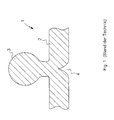
- FIG. 1 shows an electroformed mold 1 for plastics processing according to the prior art.
- the mold 1 has a mold surface 2, which is in normal use in contact with the plastic to be molded.
- a substantially omega-shaped contact profile 3 is formed galvanoplastically, resulting in a local vulnerability 4, which reduces the life of the mold 1.
- FIG. 2 shows a first embodiment of a mold 10, which also has a substantially omega-shaped investment profile 13 and a mold surface 12.
- the investment profile 13 is an extruded profile with guide portion 17 which is attached to a galvanoformed mold base 15 galvanoplastically molded flat, narrow rib 16 with guide 18 by gluing.
- FIG. 3 shows a second embodiment of a mold 20 having a substantially T-shaped abutment profile 23 and a mold surface 22.
- the investment profile 23 is an extruded profile with a guide groove 27 which is secured to a galvanoformed mold base 25 galvanoplastically molded flat, narrow rib 26 with electroformed guide portion 28 by clamping.
- FIG. 4 shows a third embodiment of a molding tool 30 having a substantially arcuate abutment profile 33 and a mold surface 32.
- the investment profile 33 is an extruded profile, wherein the top 37 is adapted to an electroformed mold base 35 galvanoplastically molded flat, narrow rib 36 to the underside of the arcuate contact profile 33.
- the investment profile 33 is welded to the flat narrow rib 36, wherein weld beads 38,39 arise at the welds, which reliably prevent the formation of an unclean edge in the field of view of the plastic part produced when using the mold 30.
Landscapes
- Engineering & Computer Science (AREA)
- Mechanical Engineering (AREA)
- Chemical & Material Sciences (AREA)
- Chemical Kinetics & Catalysis (AREA)
- Electrochemistry (AREA)
- Materials Engineering (AREA)
- Metallurgy (AREA)
- Organic Chemistry (AREA)
- Moulds For Moulding Plastics Or The Like (AREA)
Abstract
Description
- Die Erfindung betrifft ein Verfahren zur Herstellung eines Formwerkzeugs für die Kunststoffverarbeitung und ein Formwerkzeug für die Kunststoffverarbeitung.
- Formwerkzeuge, beispielsweise Formhautwerkzeuge, spielen in der kunststoffverarbeitenden Industrie eine bedeutende Rolle. Mit ihnen können Gieß- oder Slushhäute hergestellt werden, die dann hinterschäumt und/oder auf Träger aufgebracht werden können, um Kunststoffformteile herzustellen, wie sie beispielsweise in der Automobilindustrie Verwendung finden, beispielsweise für KFZ-Innenverkleidungen.
- Ein weit verbreitetes Verfahren zur Herstellung solcher Formwerkzeuge ist die Galvanoplastik, bei der die metallische Form elektrolytisch hergestellt wird. Allerdings ist es mit dieser Technik bislang kaum möglich, Formwerkzeuge herzustellen, mit denen Formhäute mit einer vorgegebenen Geometrie, insbesondere hinterschnittige Nuten, wie sie beispielsweise für die Integration von Lichtleitern in Oberflächen oder für das Abdecken des Übergangs zweifarbiger Slushhäute oder Folien mit einem Keder benötigt werden, produziert werden können. Beispiele für die Anwendung derartiger Formwerkzeuge offenbaren beispielsweise die
DE10 2009 036 678 A1 , dieDE 10 2011 089 285 A1 oder dieDE 100 62 825 A1 . - Der Grund dafür ist, dass bei der Schaffung der Aufdickung, die das zur Bildung der Nut benötigte Anlageprofil bildet, am galvanoplastisch geformten Werkzeug rückseitig eine Art Kerbe entsteht, die zu einer lokalen Schwachstelle führt, die bei der Verwendung des Werkzeugs im Serienprozess der Produktion letztlich zu seiner mechanischen Zerstörung führt.
- Dementsprechend besteht die Aufgabe der Erfindung darin, ein Verfahren zur Herstellung eines verbesserten Formwerkzeugs für die Kunststoffverarbeitung mit einem Anlageprofil sowie ein verbessertes Formwerkzeug für die Kunststoffverarbeitung mit Anlageprofil bereitzustellen. Dabei besteht die Verbesserung insbesondere einerseits in einer Vergrößerung der Menge realisierbarer Anlageprofile, also der Erschließung von Formwerkzeugen mit neuen, bislang nicht realisierbaren Anlageprofilen und andererseits in einer Erhöhung der Lebensdauer bislang schon realisierbarer Anlageprofile.
- Diese Aufgabe wird gelöst durch ein Verfahren zur Herstellung eines Formwerkzeugs für die Kunststoffverarbeitung mit einem Anlageprofil mit den Merkmalen des Anspruchs 1 und ein Formwerkzeug für die Kunststoffverarbeitung mit einem Anlageprofil mit den Merkmalen des Anspruchs 7. Weiterbildungen der Erfindung sind Gegenstand der jeweiligen Unteransprüche.
- Das erfindungsgemäße Verfahren zur Herstellung eines Formwerkzeugs für die Kunststoffverarbeitung mit mindestens einem Anlageprofil weist zumindest die Schritte
- galvanoplastisches Herstellen eines Formwerkzeugs mit flachen, schmalen Rippen an den Stellen, an denen das fertige Formwerkzeug Anlageprofile aufweisen soll,
- Bereitstellen des mindestens einen Anlageprofils, und
- Befestigen des mindestens eine Anlageprofils an den flachen, schmalen Rippen
- Das galvanoplastische Herstellen des Formwerkzeugs erfolgt dabei in an sich bekannter, üblicher Weise. Im Gegensatz zur bekannten Herstellung von Formwerkzeugen, bei der Stege angeformt werden, die die Form des Anlageprofils aufweisen, wie z.B. die Haltestege mit Omega-förmigem Querschnitt bei den Formwerkzeugen gemäß der
DE 10 2011 089 285 A1 oder derDE 10 2009 036 678 A1 , werden jedoch lediglich flache, schmale Rippen an den Stellen angeformt, an denen das fertige Werkzeug die Anlageprofile aufweisen soll. - An diesen flachen, schmalen Rippen werden dann die Anlageprofile in einem weiteren Verfahrensschritt befestigt.
- Als flache Rippen werden dabei insbesondere solche angesehen, die etwa 0,5mm bis 3mm hoch die Formwerkzeugoberfläche, die bei Verwendung des Formwerkzeugs in Kontakt mit dem Kunststoff gelangt, überragen. Schmal ist eine Rippe, wenn sie eine Breite von ca. 0,5mm bis 5 mm hat. Bei einer solchen Dimensionierung der Rippe ist es möglich, Schwächungen des Formwerkzeugs an seiner der Rippe gegenüberliegenden Seite zu vermeiden, was die Lebensdauer des Werkzeugs im Serienprozess spürbar erhöht. Gleichzeitig gewinnt man die Möglichkeit, die Anlageprofile erheblich freier zu gestalten.
- Besonders vorteilhaft ist es dabei, wenn Strangpressprofile als Anlageprofil bereitgestellt werden. Damit lassen sich unterschiedlichste Nutquerschnitte, insbesondere Omega-, Trapez- oder ähnliche Hinterschnitte, auf einfache und kostengünstige Weise realisieren.
- Insbesondere in Fällen, in denen es auf einen wohldefinierten und festen Sitz ankommt, ist es beforzugt, wenn Rippen hergestellt werden, von denen mindestens eine eine Führungsnut aufweist, wobei mindestens ein Anlageprofil bereitgestellt wird, das einen an die Geometrie der Führungsnut angepassten, vorspringenden Führungsabschnitt aufweist und/oder dass mindestens ein Anlageprofil bereitgestellt wird, das mindestens eine Führungsnut aufweist, wobei mindestens eine Rippe hergestellt wird, die einen an die Geometrie der Führungsnut angepassten, vorspringenden Führungsabschnitt aufweist. Die Führungsnuten können dabei beispielsweise eine Breite von 0,3 mm aufweisen und definieren gemeinsam mit den vorspringenden, an ihre Geometrie angepassten Führungsabschnitten eine exakte, passgenaue und sichere Anordnung der Anlageprofile.
- Das Anlageprofil kann dabei auf unterschiedliche Weisen an den flachen, schmalen Rippen befestigt werden. Wird das Anlageprofil durch Anschweißen befestigt, können ein- oder beidseitig im Übergangsbereich zwischen Rippe und Anlageprofil Schweißraupen vorgesehen werden, wodurch dann auch unsaubere Kanten im Sichtbereich effektiv verhindert werden. Wird das Anlageprofil durch Verkleben befestigt, kann der Arbeitsaufwand gegenüber einem Anschweißen verringert werden. In Fällen, in denen die Verwendung eines geeigneten Klebstoffs unerwünschte Effekte in der jeweiligen Polymerchemie hervorrufen könnte, kann das Anlageprofil auch durch Verklemmen befestigt werden.
- Das erfindungsgemäße Formwerkzeug für die Kunststoffverarbeitung hat eine Formwerkzeugoberfläche und mindestens ein Anlageprofil. Erfindungswesentlich ist, dass das mindestens eine Anlageprofil an einer an der Formwerkzeugoberfläche angeformten flachen, schmalen Rippe befestigt ist.
- Als flache Rippen werden dabei insbesondere solche angesehen, die etwa 0,5mm bis 3mm hoch die Formwerkzeugoberfläche, die bei Verwendung des Formwerkzeugs in Kontakt mit dem Kunststoff gelangt, überragen. Schmal ist eine Rippe, wenn sie eine Breite von ca. 0,5mm bis 5 mm hat.
- Durch diese Maßnahme ist es möglich, Schwächungen des Formwerkzeugs an seiner der Rippe gegenüberliegenden Seite zu vermeiden, was die Lebensdauer des Werkzeugs im Serienprozess spürbar erhöht. Gleichzeitig gewinnt man die Möglichkeit, die Anlageprofile erheblich freier zu gestalten.
- Wegen der dadurch erreichten Präzision im Hinblick auf die Anordnung der Anlageprofile ist es besonders vorteilhaft, wenn mindestens eine Rippe, an der ein Anlageprofil befestigt ist, eine Führungsnut aufweist, wobei mindestens ein Anlageprofil einen an die Geometrie der Führungsnut angepassten, vorspringenden Führungsabschnitt aufweist und/oder dass mindestens ein Anlageprofil mindestens eine Führungsnut aufweist, wobei mindestens eine Rippe einen an die Geometrie der Führungsnut angepassten, vorspringenden Führungsabschnitt aufweist. Die Führungsnuten können dabei beispielsweise eine Breite von 0,3 mm aufweisen und definieren gemeinsam mit den vorspringenden, an ihre Geometrie angepassten Führungsabschnitten eine exakte, passgenaue und sichere Anordnung der Anlageprofile.
- Die Erfindung wird nachfolgend anhand von Figuren näher erläutert. Es zeigen:
- Fig. 1:
- Ein galvanoplastisch hergestelltes Formwerkzeug mit Anlagefläche gemäß Stand der Technik,
- Fig. 2:
- ein erstes Ausführungsbeispiel für ein Formwerkzeug,
- Fig. 3:
- ein zweites Ausführungsbeispiel für ein Formwerkzeug, und
- Fig. 4:
- ein drittes Ausführungsbeispiel für ein Formwerkzeug.
-
Figur 1 zeigt ein galvanoplastisch hergestelltes Formwerkzeug 1 für die Kunststoffverarbeitung gemäß dem Stand der Technik. Das Formwerkzeug 1 weist eine Formwerkzeugoberfläche 2 auf, die bei bestimmungsgemäßer Verwendung in Kontakt mit dem zu formenden Kunststoff steht. An dem Formwerkzeug 1 ist ein im Wesentlichen Omega-förmiges Anlageprofil 3 galvanoplastisch angeformt, was zu einer lokalen Schwachstelle 4 führt, die die Lebensdauer des Formwerkzeugs 1 reduziert. -
Figur 2 zeigt ein erstes Ausführungsbeispiel für ein Formwerkzeug 10, das ebenfalls ein im Wesentlichen Omega-förmiges Anlageprofil 13 und eine Formwerkzeugoberfläche 12 aufweist. Das Anlageprofil 13 ist dabei ein Strangpressprofil mit Führungsabschnitt 17, das an einer galvanoplastisch hergestellten Formwerkzeugbasis 15 galvanoplastisch angeformten flachen, schmalen Rippe 16 mit Führungsnut 18 durch Kleben befestigt ist. -
Figur 3 zeigt ein zweites Ausführungsbeispiel für ein Formwerkzeug 20, das ein im Wesentlichen T-förmiges Anlageprofil 23 und eine Formwerkzeugoberfläche 22 aufweist. Das Anlageprofil 23 ist dabei ein Strangpressprofil mit Führungsnut 27, das an einer galvanoplastisch hergestellten Formwerkzeugbasis 25 galvanoplastisch angeformten flachen, schmalen Rippe 26 mit galvanoplastisch angeformtem Führungsabschnitt 28 durch Klemmen befestigt ist. -
Figur 4 zeigt ein drittes Ausführungsbeispiel für ein Formwerkzeug 30, das ein im Wesentlichen bogenförmiges Anlageprofil 33 und eine Formwerkzeugoberfläche 32 aufweist. Das Anlageprofil 33 ist dabei ein Strangpressprofil, wobei die Oberseite 37 einer an eine galvanoplastisch hergestellten Formwerkzeugbasis 35 galvanoplastisch angeformten flachen, schmalen Rippe 36 an die Unterseite des bogenförmigen Anlageprofils 33 angepasst ist. Das Anlageprofil 33 ist an der flachen schmalen Rippe 36 festgeschweißt, wobei Schweißraupen 38,39 an den Schweißnähten entstehen, welche bei Verwendung des Formwerkzeugs 30 das Entstehen einer unsauberen Kante im Sichtbereich des hergestellten Kunststoffteils sicher verhindern. -
- 1, 10, 20, 30
- Formwerkzeug
- 2, 12, 22, 32
- Formwerkzeugoberfläche
- 3, 13, 23, 33
- Anlageprofil
- 4
- Schwachstelle
- 15, 25, 35
- Formwerkzeugbasis
- 16, 26, 36
- Rippe
- 17, 28
- Führungsabschnitt
- 18, 27
- Führungsnut
- 37
- Oberseite
- 38, 39
- Schweißraupen
Claims (8)
- Verfahren zur Herstellung eines Formwerkzeugs (10,20,30) für die Kunststoffverarbeitung mit mindestens einem Anlageprofil (13,23,33) mit den Schritten- galvanoplastisches Herstellen eines vorläufigen Formwerkzeugs mit flachen, schmalen Rippen (16,26,36) an den Stellen, an denen das fertige Formwerkzeug (10,20,30) Anlageprofile aufweisen soll,- Bereitstellen des mindestens einen Anlageprofils (13,23, 33), und- Befestigen des mindestens einen Anlageprofils (13,23,33) an den flachen, schmalen Rippen (16,26,36).
- Verfahren nach Anspruch 1,
dadurch gekennzeichnet, dass ein Strangpressprofil als Anlageprofil (13,23,33) bereitgestellt wird. - Verfahren nach Anspruch 1 oder 2,
dadurch gekennzeichnet, dass Rippen (16) hergestellt werden, von denen mindestens eine eine Führungsnut (18)aufweist, wobei mindestens ein Anlageprofil (13) bereitgestellt wird, das einen an die Geometrie der Führungsnut (18) angepassten, vorspringenden Führungsabschnitt (17) aufweist und/oder dass mindestens ein Anlageprofil (23) bereitgestellt wird, das mindestens eine Führungsnut (27) aufweist, wobei mindestens eine Rippe (26) hergestellt wird, die einen an die Geometrie der Führungsnut angepassten, vorspringenden Führungsabschnitt (28) aufweist. - Verfahren nach einem der Ansprüche 1 bis 3,
dadurch gekennzeichnet, dass das Anlageprofil (13,23,33) durch Anschweißen befestigt wird. - Verfahren nach einem der Ansprüche 1 bis 3,
dadurch gekennzeichnet, dass das Anlageprofil (13,23,33) durch Verkleben befestigt wird. - Verfahren nach einem der Ansprüche 1 bis 3,
dadurch gekennzeichnet, dass das Anlageprofil (13,23,33) durch Verklemmen befestigt wird. - Formwerkzeug (10,20,30) für die Kunststoffverarbeitung mit einer Formwerkzeugoberfläche (12,22,32) und mindestens einem Anlageprofil (13,23,33),
dadurch gekennzeichnet, dass das mindestens eine Anlageprofil (13,23,33) an einer an der Formwerkzeugoberfläche (12,22,32) angeformten flachen, schmalen Rippe (16,26,36) befestigt ist. - Formwerkzeug (10,20,30) nach Anspruch 7,
dadurch gekennzeichnet, dass mindestens eine Rippe (16), an der ein Anlageprofil (13) befestigt ist, eine Führungsnut (18) aufweist, wobei mindestens ein Anlageprofil (13) einen an die Geometrie der Führungsnut (18) angepassten, vorspringenden Führungsabschnitt (17) aufweist und/oder dass mindestens ein Anlageprofil (23) mindestens eine Führungsnut (27) aufweist, wobei mindestens eine Rippe (26) einen an die Geometrie der Führungsnut (27) angepassten, vorspringenden Führungsabschnitt (28) aufweist.
Priority Applications (3)
| Application Number | Priority Date | Filing Date | Title |
|---|---|---|---|
| ES15163453.2T ES2678000T3 (es) | 2015-04-14 | 2015-04-14 | Procedimiento para la producción de una herramienta de moldeo para el procesamiento de plástico |
| HUE15163453A HUE038939T2 (hu) | 2015-04-14 | 2015-04-14 | Eljárás alakító szerszám elõállítására mûanyag feldolgozáshoz |
| EP15163453.2A EP3081672B1 (de) | 2015-04-14 | 2015-04-14 | Verfahren zur herstellung eines formwerkzeugs für die kunststoffverarbeitung |
Applications Claiming Priority (1)
| Application Number | Priority Date | Filing Date | Title |
|---|---|---|---|
| EP15163453.2A EP3081672B1 (de) | 2015-04-14 | 2015-04-14 | Verfahren zur herstellung eines formwerkzeugs für die kunststoffverarbeitung |
Publications (2)
| Publication Number | Publication Date |
|---|---|
| EP3081672A1 true EP3081672A1 (de) | 2016-10-19 |
| EP3081672B1 EP3081672B1 (de) | 2018-05-09 |
Family
ID=52875020
Family Applications (1)
| Application Number | Title | Priority Date | Filing Date |
|---|---|---|---|
| EP15163453.2A Active EP3081672B1 (de) | 2015-04-14 | 2015-04-14 | Verfahren zur herstellung eines formwerkzeugs für die kunststoffverarbeitung |
Country Status (3)
| Country | Link |
|---|---|
| EP (1) | EP3081672B1 (de) |
| ES (1) | ES2678000T3 (de) |
| HU (1) | HUE038939T2 (de) |
Citations (7)
| Publication number | Priority date | Publication date | Assignee | Title |
|---|---|---|---|---|
| JPH07309188A (ja) * | 1994-05-16 | 1995-11-28 | Toyota Motor Corp | エアバッグドアを有する部材の製造方法 |
| JPH10128775A (ja) * | 1996-10-25 | 1998-05-19 | Toyota Motor Corp | インストルメントパネル表皮の成形型及びその製造方法 |
| DE20009030U1 (de) * | 2000-02-23 | 2000-08-24 | Lupke, Manfred Arno Alfred, Thornhill, Ontario | Formblockabschnitt mit einstellbarer Formfläche |
| JP2002067047A (ja) * | 2000-08-28 | 2002-03-05 | Toyo Tire & Rubber Co Ltd | インストルメントパネル表皮の成形金型及びその製造方法 |
| DE10062825A1 (de) | 2000-12-15 | 2002-06-20 | Basf Ag | Verfahren und Formwerkzeug zum Herstellen von Formteilen, insbesondere für die KFZ-Innenverkleidung |
| DE102009036678A1 (de) | 2009-08-07 | 2011-02-10 | Daimler Ag | Verfahren zur Bereitstellung eines vorbestimmten Fugenbilds einer Formhaut, Formhautwerkzeug und Kraftfahrzeug-Innenverkleidungsteil mit einem in eine Formhaut integrierten Dekorfolienabschnitt |
| DE102011089285A1 (de) | 2011-12-20 | 2013-06-20 | Bayerische Motoren Werke Aktiengesellschaft | Formschlüssige Lichtintegration in Dekorhaut |
-
2015
- 2015-04-14 HU HUE15163453A patent/HUE038939T2/hu unknown
- 2015-04-14 EP EP15163453.2A patent/EP3081672B1/de active Active
- 2015-04-14 ES ES15163453.2T patent/ES2678000T3/es active Active
Patent Citations (7)
| Publication number | Priority date | Publication date | Assignee | Title |
|---|---|---|---|---|
| JPH07309188A (ja) * | 1994-05-16 | 1995-11-28 | Toyota Motor Corp | エアバッグドアを有する部材の製造方法 |
| JPH10128775A (ja) * | 1996-10-25 | 1998-05-19 | Toyota Motor Corp | インストルメントパネル表皮の成形型及びその製造方法 |
| DE20009030U1 (de) * | 2000-02-23 | 2000-08-24 | Lupke, Manfred Arno Alfred, Thornhill, Ontario | Formblockabschnitt mit einstellbarer Formfläche |
| JP2002067047A (ja) * | 2000-08-28 | 2002-03-05 | Toyo Tire & Rubber Co Ltd | インストルメントパネル表皮の成形金型及びその製造方法 |
| DE10062825A1 (de) | 2000-12-15 | 2002-06-20 | Basf Ag | Verfahren und Formwerkzeug zum Herstellen von Formteilen, insbesondere für die KFZ-Innenverkleidung |
| DE102009036678A1 (de) | 2009-08-07 | 2011-02-10 | Daimler Ag | Verfahren zur Bereitstellung eines vorbestimmten Fugenbilds einer Formhaut, Formhautwerkzeug und Kraftfahrzeug-Innenverkleidungsteil mit einem in eine Formhaut integrierten Dekorfolienabschnitt |
| DE102011089285A1 (de) | 2011-12-20 | 2013-06-20 | Bayerische Motoren Werke Aktiengesellschaft | Formschlüssige Lichtintegration in Dekorhaut |
Also Published As
| Publication number | Publication date |
|---|---|
| EP3081672B1 (de) | 2018-05-09 |
| HUE038939T2 (hu) | 2018-12-28 |
| ES2678000T3 (es) | 2018-08-08 |
Similar Documents
| Publication | Publication Date | Title |
|---|---|---|
| EP0076924B1 (de) | Verfahren zur Herstellung eines Dichtungs- und Halteprofils und Vorrichtung zur Durchführung des Verfahrens | |
| DE3538581C2 (de) | Metallform zum Vulkanisieren von Fahrzeugreifen | |
| DE102009060689A1 (de) | Verfahren zur Herstellung eines faserverstärkten Bauteils sowie Vorrichtung zur Durchführung des Verfahrens und faserverstärktes Bauteil | |
| WO2012079637A1 (de) | Zum einspannen einer turbinenschaufel eingerichtete einrichtung | |
| DE60011883T2 (de) | Formvorrichtung zum polymerisieren von profilierten teilen aus verbundwerkstoff | |
| EP0290536B1 (de) | Verfahren zur herstellung eines fensterprofiles mit einem dichtungselement | |
| DE69022863T2 (de) | Mehrteilige Form zum Giessen kleiner Segmente einer Reifenform. | |
| DE102009051392A1 (de) | Verfahren zum Herstellen eines Verbundkörpers aus mindestens einem vorzufertigenden Metallbauteil und mindesten einem Kunststoffbauteil und formschlüssig gefügter Verbundkörper | |
| EP1399308B1 (de) | Formsegment eines vulkanisierformwerkzeugs für luftreifen | |
| EP3081672B1 (de) | Verfahren zur herstellung eines formwerkzeugs für die kunststoffverarbeitung | |
| DE69701193T2 (de) | Formteil für Kraftfahrzeugkarosserie | |
| DE202007004123U1 (de) | Extrudierte Dicht- oder Abschlussleiste | |
| DE102004056479B4 (de) | Vorrichtung zum Umschäumen und/oder Umspritzen eines im Wesentlichen plattenförmigen Werkstücks | |
| EP0510034B1 (de) | Verfahren zur herstellung von vorgefertigten nahtlosen sockelleisten-eckstücken | |
| EP3412505A1 (de) | Verfahren zur herstellung eines leuchtenbauteils mit abstandshalter, entsprechend hergestelltes leuchtenbauteil, sowie mit einem solchen leuchtenbauteil ausgestattete fahrzeugleuchte | |
| DE10210968C1 (de) | Gebogenes Strangpreßprofil | |
| DE3301677C2 (de) | Verfahren und Vorrichtung zum Herstellen von Polyurethan-Formteilen | |
| DE4213466C2 (de) | Verfahren zum Herstellen von Profilleisten | |
| DE102016103775A1 (de) | Verfahren zur Herstellung eines Fahrzeugbauteils | |
| DE19508796A1 (de) | Verfahren zum Verbinden von Profilen aus elastomerem Werkstoff | |
| DE69706875T2 (de) | Verfahren zur Herstellung eines Formteiles für Kraftfahrzeugkarosserie | |
| WO2023169760A1 (de) | Verfahren und spritzgusswerkzeug zum herstellen eines bauteilverbunds | |
| DE2127720C3 (de) | Verfahren zum Fertigen von Eckstücken zum Ausrunden der Ecken von Ausschnitten eines Fahrzeugaufbaugerippes, insbesondere des Kastenaufbaus von Schienenfahrzeugen | |
| DE102007024204A1 (de) | Gussbauteil und Verfahren zum Herstellen eines Gussbauteils | |
| DE102006001453B4 (de) | Verfahren zur Herstellung von Spritzgießwerkzeugen sowie Werkzeugbausatz |
Legal Events
| Date | Code | Title | Description |
|---|---|---|---|
| PUAI | Public reference made under article 153(3) epc to a published international application that has entered the european phase |
Free format text: ORIGINAL CODE: 0009012 |
|
| AK | Designated contracting states |
Kind code of ref document: A1 Designated state(s): AL AT BE BG CH CY CZ DE DK EE ES FI FR GB GR HR HU IE IS IT LI LT LU LV MC MK MT NL NO PL PT RO RS SE SI SK SM TR |
|
| AX | Request for extension of the european patent |
Extension state: BA ME |
|
| STAA | Information on the status of an ep patent application or granted ep patent |
Free format text: STATUS: REQUEST FOR EXAMINATION WAS MADE |
|
| 17P | Request for examination filed |
Effective date: 20170321 |
|
| RBV | Designated contracting states (corrected) |
Designated state(s): AL AT BE BG CH CY CZ DE DK EE ES FI FR GB GR HR HU IE IS IT LI LT LU LV MC MK MT NL NO PL PT RO RS SE SI SK SM TR |
|
| STAA | Information on the status of an ep patent application or granted ep patent |
Free format text: STATUS: EXAMINATION IS IN PROGRESS |
|
| 17Q | First examination report despatched |
Effective date: 20170823 |
|
| GRAP | Despatch of communication of intention to grant a patent |
Free format text: ORIGINAL CODE: EPIDOSNIGR1 |
|
| STAA | Information on the status of an ep patent application or granted ep patent |
Free format text: STATUS: GRANT OF PATENT IS INTENDED |
|
| RIC1 | Information provided on ipc code assigned before grant |
Ipc: B23P 15/24 20060101ALN20180126BHEP Ipc: B29C 33/30 20060101ALI20180126BHEP Ipc: C25D 1/10 20060101AFI20180126BHEP Ipc: B29C 41/18 20060101ALN20180126BHEP Ipc: B29L 31/30 20060101ALN20180126BHEP Ipc: B29C 33/42 20060101ALI20180126BHEP |
|
| INTG | Intention to grant announced |
Effective date: 20180222 |
|
| GRAS | Grant fee paid |
Free format text: ORIGINAL CODE: EPIDOSNIGR3 |
|
| GRAA | (expected) grant |
Free format text: ORIGINAL CODE: 0009210 |
|
| STAA | Information on the status of an ep patent application or granted ep patent |
Free format text: STATUS: THE PATENT HAS BEEN GRANTED |
|
| AK | Designated contracting states |
Kind code of ref document: B1 Designated state(s): AL AT BE BG CH CY CZ DE DK EE ES FI FR GB GR HR HU IE IS IT LI LT LU LV MC MK MT NL NO PL PT RO RS SE SI SK SM TR |
|
| REG | Reference to a national code |
Ref country code: GB Ref legal event code: FG4D Free format text: NOT ENGLISH |
|
| REG | Reference to a national code |
Ref country code: CH Ref legal event code: EP Ref country code: AT Ref legal event code: REF Ref document number: 997644 Country of ref document: AT Kind code of ref document: T Effective date: 20180515 |
|
| REG | Reference to a national code |
Ref country code: IE Ref legal event code: FG4D Free format text: LANGUAGE OF EP DOCUMENT: GERMAN |
|
| REG | Reference to a national code |
Ref country code: DE Ref legal event code: R096 Ref document number: 502015004174 Country of ref document: DE |
|
| REG | Reference to a national code |
Ref country code: ES Ref legal event code: FG2A Ref document number: 2678000 Country of ref document: ES Kind code of ref document: T3 Effective date: 20180808 |
|
| REG | Reference to a national code |
Ref country code: NL Ref legal event code: MP Effective date: 20180509 |
|
| REG | Reference to a national code |
Ref country code: LT Ref legal event code: MG4D |
|
| PG25 | Lapsed in a contracting state [announced via postgrant information from national office to epo] |
Ref country code: FI Free format text: LAPSE BECAUSE OF FAILURE TO SUBMIT A TRANSLATION OF THE DESCRIPTION OR TO PAY THE FEE WITHIN THE PRESCRIBED TIME-LIMIT Effective date: 20180509 Ref country code: NO Free format text: LAPSE BECAUSE OF FAILURE TO SUBMIT A TRANSLATION OF THE DESCRIPTION OR TO PAY THE FEE WITHIN THE PRESCRIBED TIME-LIMIT Effective date: 20180809 Ref country code: SE Free format text: LAPSE BECAUSE OF FAILURE TO SUBMIT A TRANSLATION OF THE DESCRIPTION OR TO PAY THE FEE WITHIN THE PRESCRIBED TIME-LIMIT Effective date: 20180509 Ref country code: LT Free format text: LAPSE BECAUSE OF FAILURE TO SUBMIT A TRANSLATION OF THE DESCRIPTION OR TO PAY THE FEE WITHIN THE PRESCRIBED TIME-LIMIT Effective date: 20180509 Ref country code: BG Free format text: LAPSE BECAUSE OF FAILURE TO SUBMIT A TRANSLATION OF THE DESCRIPTION OR TO PAY THE FEE WITHIN THE PRESCRIBED TIME-LIMIT Effective date: 20180809 |
|
| REG | Reference to a national code |
Ref country code: SK Ref legal event code: T3 Ref document number: E 27907 Country of ref document: SK |
|
| PG25 | Lapsed in a contracting state [announced via postgrant information from national office to epo] |
Ref country code: RS Free format text: LAPSE BECAUSE OF FAILURE TO SUBMIT A TRANSLATION OF THE DESCRIPTION OR TO PAY THE FEE WITHIN THE PRESCRIBED TIME-LIMIT Effective date: 20180509 Ref country code: LV Free format text: LAPSE BECAUSE OF FAILURE TO SUBMIT A TRANSLATION OF THE DESCRIPTION OR TO PAY THE FEE WITHIN THE PRESCRIBED TIME-LIMIT Effective date: 20180509 Ref country code: NL Free format text: LAPSE BECAUSE OF FAILURE TO SUBMIT A TRANSLATION OF THE DESCRIPTION OR TO PAY THE FEE WITHIN THE PRESCRIBED TIME-LIMIT Effective date: 20180509 Ref country code: GR Free format text: LAPSE BECAUSE OF FAILURE TO SUBMIT A TRANSLATION OF THE DESCRIPTION OR TO PAY THE FEE WITHIN THE PRESCRIBED TIME-LIMIT Effective date: 20180810 Ref country code: HR Free format text: LAPSE BECAUSE OF FAILURE TO SUBMIT A TRANSLATION OF THE DESCRIPTION OR TO PAY THE FEE WITHIN THE PRESCRIBED TIME-LIMIT Effective date: 20180509 |
|
| REG | Reference to a national code |
Ref country code: HU Ref legal event code: AG4A Ref document number: E038939 Country of ref document: HU |
|
| PG25 | Lapsed in a contracting state [announced via postgrant information from national office to epo] |
Ref country code: EE Free format text: LAPSE BECAUSE OF FAILURE TO SUBMIT A TRANSLATION OF THE DESCRIPTION OR TO PAY THE FEE WITHIN THE PRESCRIBED TIME-LIMIT Effective date: 20180509 Ref country code: PL Free format text: LAPSE BECAUSE OF FAILURE TO SUBMIT A TRANSLATION OF THE DESCRIPTION OR TO PAY THE FEE WITHIN THE PRESCRIBED TIME-LIMIT Effective date: 20180509 Ref country code: DK Free format text: LAPSE BECAUSE OF FAILURE TO SUBMIT A TRANSLATION OF THE DESCRIPTION OR TO PAY THE FEE WITHIN THE PRESCRIBED TIME-LIMIT Effective date: 20180509 Ref country code: CZ Free format text: LAPSE BECAUSE OF FAILURE TO SUBMIT A TRANSLATION OF THE DESCRIPTION OR TO PAY THE FEE WITHIN THE PRESCRIBED TIME-LIMIT Effective date: 20180509 Ref country code: RO Free format text: LAPSE BECAUSE OF FAILURE TO SUBMIT A TRANSLATION OF THE DESCRIPTION OR TO PAY THE FEE WITHIN THE PRESCRIBED TIME-LIMIT Effective date: 20180509 |
|
| REG | Reference to a national code |
Ref country code: DE Ref legal event code: R097 Ref document number: 502015004174 Country of ref document: DE |
|
| PG25 | Lapsed in a contracting state [announced via postgrant information from national office to epo] |
Ref country code: SM Free format text: LAPSE BECAUSE OF FAILURE TO SUBMIT A TRANSLATION OF THE DESCRIPTION OR TO PAY THE FEE WITHIN THE PRESCRIBED TIME-LIMIT Effective date: 20180509 Ref country code: IT Free format text: LAPSE BECAUSE OF FAILURE TO SUBMIT A TRANSLATION OF THE DESCRIPTION OR TO PAY THE FEE WITHIN THE PRESCRIBED TIME-LIMIT Effective date: 20180509 |
|
| PLBE | No opposition filed within time limit |
Free format text: ORIGINAL CODE: 0009261 |
|
| STAA | Information on the status of an ep patent application or granted ep patent |
Free format text: STATUS: NO OPPOSITION FILED WITHIN TIME LIMIT |
|
| 26N | No opposition filed |
Effective date: 20190212 |
|
| PG25 | Lapsed in a contracting state [announced via postgrant information from national office to epo] |
Ref country code: SI Free format text: LAPSE BECAUSE OF FAILURE TO SUBMIT A TRANSLATION OF THE DESCRIPTION OR TO PAY THE FEE WITHIN THE PRESCRIBED TIME-LIMIT Effective date: 20180509 |
|
| PG25 | Lapsed in a contracting state [announced via postgrant information from national office to epo] |
Ref country code: AL Free format text: LAPSE BECAUSE OF FAILURE TO SUBMIT A TRANSLATION OF THE DESCRIPTION OR TO PAY THE FEE WITHIN THE PRESCRIBED TIME-LIMIT Effective date: 20180509 |
|
| REG | Reference to a national code |
Ref country code: CH Ref legal event code: PL |
|
| REG | Reference to a national code |
Ref country code: BE Ref legal event code: MM Effective date: 20190430 |
|
| GBPC | Gb: european patent ceased through non-payment of renewal fee |
Effective date: 20190414 |
|
| PG25 | Lapsed in a contracting state [announced via postgrant information from national office to epo] |
Ref country code: LU Free format text: LAPSE BECAUSE OF NON-PAYMENT OF DUE FEES Effective date: 20190414 Ref country code: MC Free format text: LAPSE BECAUSE OF FAILURE TO SUBMIT A TRANSLATION OF THE DESCRIPTION OR TO PAY THE FEE WITHIN THE PRESCRIBED TIME-LIMIT Effective date: 20180509 |
|
| PG25 | Lapsed in a contracting state [announced via postgrant information from national office to epo] |
Ref country code: GB Free format text: LAPSE BECAUSE OF NON-PAYMENT OF DUE FEES Effective date: 20190414 Ref country code: CH Free format text: LAPSE BECAUSE OF NON-PAYMENT OF DUE FEES Effective date: 20190430 Ref country code: LI Free format text: LAPSE BECAUSE OF NON-PAYMENT OF DUE FEES Effective date: 20190430 |
|
| PG25 | Lapsed in a contracting state [announced via postgrant information from national office to epo] |
Ref country code: BE Free format text: LAPSE BECAUSE OF NON-PAYMENT OF DUE FEES Effective date: 20190430 |
|
| PG25 | Lapsed in a contracting state [announced via postgrant information from national office to epo] |
Ref country code: TR Free format text: LAPSE BECAUSE OF FAILURE TO SUBMIT A TRANSLATION OF THE DESCRIPTION OR TO PAY THE FEE WITHIN THE PRESCRIBED TIME-LIMIT Effective date: 20180509 |
|
| PG25 | Lapsed in a contracting state [announced via postgrant information from national office to epo] |
Ref country code: IE Free format text: LAPSE BECAUSE OF NON-PAYMENT OF DUE FEES Effective date: 20190414 |
|
| PG25 | Lapsed in a contracting state [announced via postgrant information from national office to epo] |
Ref country code: PT Free format text: LAPSE BECAUSE OF FAILURE TO SUBMIT A TRANSLATION OF THE DESCRIPTION OR TO PAY THE FEE WITHIN THE PRESCRIBED TIME-LIMIT Effective date: 20180910 |
|
| PG25 | Lapsed in a contracting state [announced via postgrant information from national office to epo] |
Ref country code: CY Free format text: LAPSE BECAUSE OF FAILURE TO SUBMIT A TRANSLATION OF THE DESCRIPTION OR TO PAY THE FEE WITHIN THE PRESCRIBED TIME-LIMIT Effective date: 20180509 |
|
| REG | Reference to a national code |
Ref country code: AT Ref legal event code: MM01 Ref document number: 997644 Country of ref document: AT Kind code of ref document: T Effective date: 20200414 |
|
| PG25 | Lapsed in a contracting state [announced via postgrant information from national office to epo] |
Ref country code: IS Free format text: LAPSE BECAUSE OF FAILURE TO SUBMIT A TRANSLATION OF THE DESCRIPTION OR TO PAY THE FEE WITHIN THE PRESCRIBED TIME-LIMIT Effective date: 20180909 |
|
| PG25 | Lapsed in a contracting state [announced via postgrant information from national office to epo] |
Ref country code: MT Free format text: LAPSE BECAUSE OF FAILURE TO SUBMIT A TRANSLATION OF THE DESCRIPTION OR TO PAY THE FEE WITHIN THE PRESCRIBED TIME-LIMIT Effective date: 20180509 |
|
| PG25 | Lapsed in a contracting state [announced via postgrant information from national office to epo] |
Ref country code: AT Free format text: LAPSE BECAUSE OF NON-PAYMENT OF DUE FEES Effective date: 20200414 |
|
| PG25 | Lapsed in a contracting state [announced via postgrant information from national office to epo] |
Ref country code: MK Free format text: LAPSE BECAUSE OF FAILURE TO SUBMIT A TRANSLATION OF THE DESCRIPTION OR TO PAY THE FEE WITHIN THE PRESCRIBED TIME-LIMIT Effective date: 20180509 |
|
| P01 | Opt-out of the competence of the unified patent court (upc) registered |
Effective date: 20230427 |
|
| PGFP | Annual fee paid to national office [announced via postgrant information from national office to epo] |
Ref country code: DE Payment date: 20240418 Year of fee payment: 10 |
|
| PGFP | Annual fee paid to national office [announced via postgrant information from national office to epo] |
Ref country code: ES Payment date: 20240517 Year of fee payment: 10 |
|
| PGFP | Annual fee paid to national office [announced via postgrant information from national office to epo] |
Ref country code: SK Payment date: 20240405 Year of fee payment: 10 |
|
| PGFP | Annual fee paid to national office [announced via postgrant information from national office to epo] |
Ref country code: FR Payment date: 20240419 Year of fee payment: 10 |
|
| PGFP | Annual fee paid to national office [announced via postgrant information from national office to epo] |
Ref country code: HU Payment date: 20240410 Year of fee payment: 10 |