EP3081180B1 - Fixationssystem für knochen - Google Patents
Fixationssystem für knochen Download PDFInfo
- Publication number
- EP3081180B1 EP3081180B1 EP16173279.7A EP16173279A EP3081180B1 EP 3081180 B1 EP3081180 B1 EP 3081180B1 EP 16173279 A EP16173279 A EP 16173279A EP 3081180 B1 EP3081180 B1 EP 3081180B1
- Authority
- EP
- European Patent Office
- Prior art keywords
- round hole
- rib
- bone
- screw
- plate
- Prior art date
- Legal status (The legal status is an assumption and is not a legal conclusion. Google has not performed a legal analysis and makes no representation as to the accuracy of the status listed.)
- Active
Links
- 210000000988 bone and bone Anatomy 0.000 title claims description 130
- 239000000463 material Substances 0.000 claims description 16
- 230000015572 biosynthetic process Effects 0.000 claims description 14
- 238000005755 formation reaction Methods 0.000 claims description 14
- 238000003780 insertion Methods 0.000 claims description 8
- 230000037431 insertion Effects 0.000 claims description 8
- 230000006978 adaptation Effects 0.000 claims description 3
- 230000007704 transition Effects 0.000 claims description 3
- 239000012634 fragment Substances 0.000 description 9
- 229920003023 plastic Polymers 0.000 description 4
- 239000004033 plastic Substances 0.000 description 4
- 239000000956 alloy Substances 0.000 description 3
- 229910045601 alloy Inorganic materials 0.000 description 3
- 238000006073 displacement reaction Methods 0.000 description 3
- 229910000831 Steel Inorganic materials 0.000 description 2
- 239000007943 implant Substances 0.000 description 2
- JVTAAEKCZFNVCJ-UHFFFAOYSA-N lactic acid Chemical compound CC(O)C(O)=O JVTAAEKCZFNVCJ-UHFFFAOYSA-N 0.000 description 2
- 229910052751 metal Inorganic materials 0.000 description 2
- 239000002184 metal Substances 0.000 description 2
- 150000002739 metals Chemical class 0.000 description 2
- 239000010959 steel Substances 0.000 description 2
- 241000446313 Lamella Species 0.000 description 1
- FYYHWMGAXLPEAU-UHFFFAOYSA-N Magnesium Chemical compound [Mg] FYYHWMGAXLPEAU-UHFFFAOYSA-N 0.000 description 1
- RTAQQCXQSZGOHL-UHFFFAOYSA-N Titanium Chemical compound [Ti] RTAQQCXQSZGOHL-UHFFFAOYSA-N 0.000 description 1
- 230000006835 compression Effects 0.000 description 1
- 238000007906 compression Methods 0.000 description 1
- 230000000694 effects Effects 0.000 description 1
- 210000000610 foot bone Anatomy 0.000 description 1
- 210000002411 hand bone Anatomy 0.000 description 1
- 235000014655 lactic acid Nutrition 0.000 description 1
- 239000004310 lactic acid Substances 0.000 description 1
- 229910052749 magnesium Inorganic materials 0.000 description 1
- 239000011777 magnesium Substances 0.000 description 1
- 238000004519 manufacturing process Methods 0.000 description 1
- 230000002093 peripheral effect Effects 0.000 description 1
- 239000010936 titanium Substances 0.000 description 1
- 229910052719 titanium Inorganic materials 0.000 description 1
- 210000000689 upper leg Anatomy 0.000 description 1
Images


Classifications
-
- A—HUMAN NECESSITIES
- A61—MEDICAL OR VETERINARY SCIENCE; HYGIENE
- A61B—DIAGNOSIS; SURGERY; IDENTIFICATION
- A61B17/00—Surgical instruments, devices or methods, e.g. tourniquets
- A61B17/56—Surgical instruments or methods for treatment of bones or joints; Devices specially adapted therefor
- A61B17/58—Surgical instruments or methods for treatment of bones or joints; Devices specially adapted therefor for osteosynthesis, e.g. bone plates, screws, setting implements or the like
- A61B17/68—Internal fixation devices, including fasteners and spinal fixators, even if a part thereof projects from the skin
- A61B17/84—Fasteners therefor or fasteners being internal fixation devices
- A61B17/86—Pins or screws or threaded wires; nuts therefor
- A61B17/8605—Heads, i.e. proximal ends projecting from bone
-
- A—HUMAN NECESSITIES
- A61—MEDICAL OR VETERINARY SCIENCE; HYGIENE
- A61B—DIAGNOSIS; SURGERY; IDENTIFICATION
- A61B17/00—Surgical instruments, devices or methods, e.g. tourniquets
- A61B17/56—Surgical instruments or methods for treatment of bones or joints; Devices specially adapted therefor
- A61B17/58—Surgical instruments or methods for treatment of bones or joints; Devices specially adapted therefor for osteosynthesis, e.g. bone plates, screws, setting implements or the like
- A61B17/68—Internal fixation devices, including fasteners and spinal fixators, even if a part thereof projects from the skin
- A61B17/80—Cortical plates, i.e. bone plates; Instruments for holding or positioning cortical plates, or for compressing bones attached to cortical plates
- A61B17/8004—Cortical plates, i.e. bone plates; Instruments for holding or positioning cortical plates, or for compressing bones attached to cortical plates with means for distracting or compressing the bone or bones
- A61B17/8014—Cortical plates, i.e. bone plates; Instruments for holding or positioning cortical plates, or for compressing bones attached to cortical plates with means for distracting or compressing the bone or bones the extension or compression force being caused by interaction of the plate hole and the screws
-
- A—HUMAN NECESSITIES
- A61—MEDICAL OR VETERINARY SCIENCE; HYGIENE
- A61B—DIAGNOSIS; SURGERY; IDENTIFICATION
- A61B17/00—Surgical instruments, devices or methods, e.g. tourniquets
- A61B17/56—Surgical instruments or methods for treatment of bones or joints; Devices specially adapted therefor
- A61B17/58—Surgical instruments or methods for treatment of bones or joints; Devices specially adapted therefor for osteosynthesis, e.g. bone plates, screws, setting implements or the like
- A61B17/68—Internal fixation devices, including fasteners and spinal fixators, even if a part thereof projects from the skin
- A61B17/80—Cortical plates, i.e. bone plates; Instruments for holding or positioning cortical plates, or for compressing bones attached to cortical plates
- A61B17/8052—Cortical plates, i.e. bone plates; Instruments for holding or positioning cortical plates, or for compressing bones attached to cortical plates immobilised relative to screws by interlocking form of the heads and plate holes, e.g. conical or threaded
-
- A—HUMAN NECESSITIES
- A61—MEDICAL OR VETERINARY SCIENCE; HYGIENE
- A61B—DIAGNOSIS; SURGERY; IDENTIFICATION
- A61B17/00—Surgical instruments, devices or methods, e.g. tourniquets
- A61B2017/00004—(bio)absorbable, (bio)resorbable, resorptive
Definitions
- the invention relates to a fixation system for bones with bone screws and a bone plate which has a plurality of holes arranged in the direction of the plate's longitudinal axis for receiving bone screws.
- the holes towards the top of the bone plate are designed to be spherical all around in order to be able to support a bone screw with a spherical underside of the head in different angular positions.
- the holes On the underside of the plate, adjacent to the bone, the holes have an area of smaller diameter with a partial thread in order to also be able to receive a bone screw with a cylindrical threaded head, which is to be countersunk perpendicular to the plane of the plate.
- elongated holes with an internal thread which extends at one end of the elongated hole from the top to the bottom of the bone plate and has a circumferential or central angle in the range of 190-280 °.
- the internal thread occupies the entire depth of the elongated hole, tapers conically towards the underside of the bone plate and has a cone angle in the range from 5 to 20 °.
- elongated holes are provided in the bone plate, which can be oval, elliptical or rectangular or contain a combination of such shapes; only circular holes have been explicitly excluded from this definition of the elongated hole.
- the elongated hole is combined with a circular hole and this is provided with a three-dimensional structure, which is in the form of an internal thread or a peripheral lamella or lip.
- a conical internal thread is shown which extends from the top to the bottom of the bone plate and has a circumferential or central angle in the range from 190 to 280 °.
- a fixation system for bones with a bone plate which has elongated holes as through-holes which, near its underside adjacent to the bone, has projections which extend in the lower part of the elongated hole parallel to the plane of the plate.
- On the upper side of the bone plate there are seats for the ball heads of the bone screws.
- the seat surfaces are designed as inwardly inclined conical surfaces or spherical surfaces.
- the bone screw has a short piece of thread below the ball head which is able to deform and transform the resilient projections in the elongated hole.
- the seating surfaces of the bone plate and the bone screw make it possible to fix the bone screw in different angular positions with respect to the axis of the through holes.
- the document EP 1 859 752 A1 shows a fixation system with a bone plate and a bone screw, in which an angle-stable connection is made possible with simultaneous compression of the bones.
- the invention is based on the object of creating a fixation system with bone screws and a bone plate in which different types of bone screws - those with conical seating surfaces and those with spherical seating surfaces - can be used in order to meet the various requirements when fixing a broken or damaged bone. In particular, it should be possible to move bone fragments relative to one another during fixation.
- the new fixation system is made up of two types of bone screws and a bone plate, whereby with the first type of bone screw only screwing is possible perpendicular to the plate shape of the bone plate, which for this purpose has a radial rib and a conical seat, while with the second type of bone screw at an inclined angle can be worked to the plane of the plate, with no engagement of the bone screw in the radial rib.
- the second type of bone screw has partially spherical surfaces on the underside of the head, but no thread for engaging the bone plate.
- the bone plate has a preferably elongated plate body made of a first, fabric-compatible, rigid material that defines a top and bottom and a longitudinal axis. Hole formations are provided transversely to the plane of the plate, which consist of a first, larger round hole and a second, smaller round hole, the round holes intersecting to form edges, between which a passage is formed for the screw shaft of an obliquely set bone screw.
- a radial rib is provided around both round holes, which starts from the wall of the hole and extends in a plane close to the screw insertion side towards the center of the round hole.
- the first type of bone screw is provided with a thread on the screw head and can optionally be supported on the rib of the smaller round hole and screwed to the rib of the larger round hole, whereby deformation and mutual shape adaptation takes place.
- this deformation retains a permanent component even after the bone screw has been separated from the bone plate, which means that this deformation also includes plastic deformations beyond the purely elastic component.
- This plastically deformed, permanent portion of the deformation can, depending on the material and configuration of the structural dimensions, be present solely in the bone screw, can be present alone in the bone plate or can also be present in both the bone screw and the bone plate.
- the plastic, remaining portion is in each case in a type of furrow or groove, which at least has a depth of 10 ⁇ m, preferably more than 100 ⁇ m and particularly preferably more than 200 ⁇ m.
- the first, larger round hole has three sections, namely an upper, fillet-shaped section above the circumferential rib, a central, fillet-shaped section below the circumferential rib, and a lower, frustoconical section that tapers towards the underside of the plate body and its largest diameter is smaller than the diameter of the top or middle section.
- the smaller round hole comprises an upper section with an inclined transition area to the top of the plate, furthermore a middle section below the plane of the circumferential rib with an inclined-rounded surface and a lower, cylindrical or conical section with a diameter smaller than the diameter of the upper or middle section .
- bone screws of the first type can be used with a head which is provided in its upper area with screw thread and in its lower area with a conical seat surface, in such a way that when screwing eccentrically into a bone perpendicular to the plane of the plate Displacement of the head relative to the hole formation takes place, such that bone fragments can be brought closer together when fixing.
- the new bone plate also enables the use of bone screws of the second type with spherical seat surfaces on the underside of the screw head.
- Such ball head screws can be screwed in at an angle to the bone plate, with the screw shaft in the bone is anchored and the fixation is carried out by placing the spherical seat of the head on the matching seat of the bone plate.
- the figures show the piece of a bone plate, which consists of an elongated plate body 1 made of a first, tissue-compatible, rigid material and in which a series of hole configurations are made, of which a hole configuration 2 is shown.
- the plate body 1 can also be oval, round or polygonal or its shape can be adapted to the respective application.
- Tissue-compatible material is understood to mean, for example, metals and their alloys, such as are usually used for the production of implants.
- Preferred metals include titanium in any form, preferably also its alloys TiAl6V4 and TiCp ..
- PLA is a biocompatible and absorbable plastic made of chemically bonded lactic acid molecules, which can be used like other absorbable plastics.
- a bone plate is considered to be stiff if it provides the necessary stiffness for its intended use and application. Depending on the tissue-compatible material used, this can be ensured by the thickness and width of the plate and is usually within the range of professional action.
- bone plates for small and less stressed parts of the body are thinner and often less wide than bone plates for larger and more stressed parts, such as parts of the lower leg and thigh.
- the bone plate has an upper side 11 and an underside 12, which usually run parallel to the plane of the plate, the underside 12 being adjacent to the bone to be fixed.
- the hole formations 2 are lined up along the longitudinal axis of the elongated plate body 1 and consist of two stepped round holes, 21 and 22, which extend transversely to the plate plane and their Axes 21a, 22a intersect the longitudinal axis of the bone plate.
- the smallest diameter of the first round hole 21 is larger than the smallest diameter of the second round hole 22 and the distance between the two axes 21a and 22a is smaller than the smallest diameter of the first round hole 21.
- edges 23, 24 delimit the areas of the round holes from one another and leave a passage for the relatively thin screw shaft of a bone screw if, when a bone screw is inclined, it extends from one round hole into the other round hole.
- the circumferential angles of the wall reveals of the round holes 21, 22 are approx. 250 ° of the larger hole and approx. 220 ° of the smaller hole. Variations by 10 ° smaller and 20 ° larger are possible.
- an upper region 25 and a lower region 26 of the round hole 21 and an upper region 27 and a lower region 28 of the round hole 22 can be distinguished.
- the upper regions 25 and 27 are designed in the shape of a bowl, while the lower regions 26 and 28 form jacket surfaces with straight jacket lines.
- the upper regions 25 and 27 have larger diameters compared to the lower regions 26 and 28.
- the lower region 26 forms a frustoconical section which tapers towards the underside of the plate body 1.
- the lower region 28 is cylindrical, but it can also be designed in the shape of a truncated cone.
- a radial rib 33 extends in a plane around the hole formation 2, starting from the hole walls.
- the rib 33 is designed as a circumferential web and has a wedge-shaped cross-section which tapers towards the center of the respective round hole. In plan view, the rib 33 appears to be similar to a figure eight.
- a ridge 61 is arranged parallel to the plane of the rib 33 on the outer edge of the larger round hole 21 for the rib part attached to the larger round hole, whereby an edge 24 is formed towards the second round hole 22.
- the height of the ridge 61 increases towards the edge of the plate body 1, as best from the comparison of FIG Fig. 4 With Fig. 3 emerges.
- a gear guide is formed between the ridge 61 and the rib 33, which facilitates the engagement of the thread 41 of the head screw 40.
- each of the two round holes 21, 22 is divided into three sections: the larger round hole 21 has an upper, round valley-shaped section 31 with or without a ridge 61 above the rib 33, and below the rib 33 there is a central, round valley-shaped section 36 and a lower, frustoconical section 26 is provided.
- the smaller round hole 22 comprises an upper section 35 with an insertion bevel 62, a middle section 36 with an inclined-rounded surface 63 below the plane of the rib 33, and a lower section 28 which is preferably cylindrical, but can also be conical.
- the bone plate is designed to interact with at least two types of bone screws.
- the second type has a bone screw head with a partially spherical underside and can be supported with the underside of the head on the inclined, rounded surface 63 of the bone plate. It is also possible to position the screw axis at an angle relative to the plane of the plate, both in the longitudinal direction and (to a lesser extent) in the transverse direction to the bone plate. This is made possible by the spacing of the edges 23 from one another, which is greater than the diameter of the screw shaft of the bone screw.
- the first type of applicable bone screw 4 is in Fig. 4 shown.
- This bone screw 4 has a screw head 40 with internal engagement and with a thread 41 designed as an external thread at the upper end and a conical seat 42 designed as a support surface at the lower end, the taper of which corresponds to the taper of the lower region 26 of the larger round hole 21.
- the thread 41 can be cylindrical, but a conical thread is preferred.
- the conical inclination of the lower region 26 of the larger round hole 21 and the conical inclination of the conical seat surface 42 at the lower end of the screw head 40 of the bone screw have an angle relative to the longitudinal or symmetry axis of the bone screw or the round hole 21 in the range of 3 to 30 °.
- This cone angle is preferably in a range from 6 to 20 ° and most preferably in a range from 8 to 12 °.
- a particularly preferred design has a cone angle of about 10 ° with high fatigue strength values and good releasability of the connection between the bone screw and the bone plate.
- the screw head 40 is followed by a screw shaft 43 which is intended to be anchored in a bone element to be fixed.
- the circumferential rib 33 extends in a plane, preferably parallel to the plane of the plate, while the thread 41 extends along screw surfaces which naturally run obliquely with respect to the plane of the radial rib 33, even when the bone screw 4 is intended to be parallel or co-rotating is screwed to the axis 21a of the round hole 21.
- the shape of the thread and the rib 33 are mutually adapted.
- the ridge 61 is useful because it provides a counter-bearing for the thread of the screw head.
- the mutual adaptation of shape requires a certain flexibility of the (first) material of the bone plate at least in the area of the radial rib 33 and / or of the (second) material of the bone screw at least in the area of the thread 41. It is preferred to make the (second) material of the bone screw harder than the (first) material of the bone plate and also to choose a shape with a greater section modulus for the thread 41 compared to that of the rib 33. In this way the "softer" rib lying in one plane adapts largely the engagement screw thread 41 when the fixation system is used as intended. Nevertheless, it is also within the scope of the invention that the first and second materials have the same hardness at least in the area of the radial rib 33 and the thread 41.
- the same material can be used both for the bone screws and for the bone plate and corrosive effects in the area and in the vicinity of the contact points between the bone screw and the bone plate can be reliably avoided.
- the bone screw 4 can be used to bring bone fragments closer together and to compress them.
- the bone screw 4 is placed with its axis parallel to the axis 22a in the area of the round hole 22.
- a lateral force is exerted on the screw head 40 when the screw is screwed in, which leads to a displacement of the bone fragment to be fixed relative to the bone plate. Accordingly, if a bone fragment is already firmly connected to the bone plate, this bone fragment is pushed against the bone fragment to be fixed, as is desired.
- FIGs. 5-8 a further particularly preferred embodiment of the bone plate is shown, the same reference numerals being used for corresponding parts.
- the main difference is the design of the circumferential radial rib 33. This is partially cut away in the area of the smaller round hole 22 in order to create an inclined, rounded sliding surface 35a and a transition surface 35b, which is used to guide the head of a bone screw with a partially spherical underside of the head or to guide the screw with a conical seat surface 42 are useful.
- a residual rib 37 is formed which increases to the full size of the rib 33 in the area of the larger round hole 21.
- the remaining edge 34 extends by less than 180 ° and thus allows the lateral introduction of bone screws from the smaller round hole 22 into the larger round hole 21.
- the rib 33 has a wedge-shaped cross section with an upper side inclined towards the center of the hole and an underside parallel to the plane of the plate. In this way, the section modulus of the rib 33 is significantly smaller than the section modulus of the screw thread in engagement with the rib, so the rib 33 is more flexible even if the materials of the rib and screw thread are of the same hardness. However, a lower hardness of the rib 33 is preferred for the purpose of adapting the shape.
- a fixation system for bones with a bone plate and bone screws is created, in which bone screws with a round head can be set at different angles to the bone plate. Furthermore, when using bone screws with a conical head, the fixation system enables the relative displacement between the bone fragment to be fixed and the bone plate, which enables the surgeon to move bone fragments against one another when they are fixed.
Description
- Die Erfindung bezieht sich auf ein Fixationssystem für Knochen mit Knochenschrauben und einer Knochenplatte, die mehrere in Richtung der Plattenlängsachse angeordnete Löcher für die Aufnahme von Knochenschrauben aufweist.
- Bei einer bekannten Knochenplatte (
EP 0760632 B1 ) sind die Löcher zur Oberseite der Knochenplatte hin rundum sphärisch ausgebildet, um eine Knochenschraube mit kugeliger Unterseite des Kopfes in unterschiedlichen Winkelstellungen abstützen zu können. An der Plattenunterseite benachbart zum Knochen weisen die Löcher einen Bereich kleineren Durchmessers mit partiellem Gewinde auf, um auch eine Knochenschraube mit zylindrischem Gewindekopf aufnehmen zu können, die senkrecht zur Plattenebene eingesenkt werden soll. - Bei einer weiteren Knochenplatte (
EP 1158915 B1 undEP 1158916 B1 ) sind Langlöcher mit einem Innengewinde, das sich an einem Ende des Langlochs von der Oberseite bis zur Unterseite der Knochenplatte erstreckt und einen Umfangs- oder Zentriwinkel im Bereich von 190-280°aufweist, vorhanden. Das Innengewinde nimmt die gesamte Tiefe des Langloches ein, verjüngt sich gegen die Unterseite der Knochenplatte hin konisch und weist einen Konuswinkel im Bereich von 5 bis 20°auf. - Bei einer weiteren bekannten Knochenplatte (
EP 1255498 B1 ) sind Langlöcher in der Knochenplatte vorgesehen, die oval, elipsenförmig oder auch rechteckig ausgebildet sein können oder eine Kombination solcher Formen beinhalten; lediglich kreisrunde Löcher sind von dieser Definition des Langlochs explizit ausgeschlossen worden. Das Langloch ist mit einem kreisförmigen Loch kombiniert und dieses ist mit einer dreidimensionalen Strukturierung versehen, welche in Form eines Innengewindes oder einer peripheren Lamelle oder Lippe vorliegt. Dargestellt ist ein konisches Innengewinde, das sich von der Oberseite bis zur Unterseite der Knochenplatte erstreckt und einen Umfangs- oder Zentriwinkel im Bereich von 190 bis 280° aufweist. - Aus
DE 19858889 A1 ist ein Fixationssystem für Knochen mit einer Knochenplatte bekannt, welche Langlöcher als Durchgangslöcher besitzt, die nahe ihrer dem Knochen benachbarten Unterseite Vorsprünge aufweist, welche sich im unteren Teil des Langloches parallel zur Plattenebene erstrecken. Zur Oberseite der Knochenplatte hin gibt es Sitzflächen für Kugelköpfe der Knochenschrauben. Die Sitzflächen sind als nach innen geneigte Konusflächen oder Kugelflächen ausgebildet. Um mit den Vorsprüngen in der Knochenplatte zusammen zu arbeiten, weist die Knochenschraube unterhalb des Kugelkopfes ein kurzes Stück Gewinde auf, das in der Lage ist, die nachgiebigen Vorsprünge in dem Langloch zu deformieren und sich anzuverwandeln. Die Sitzflächen der Knochenplatte und der Knochenschraube machen es möglich, die Knochenschraube in verschiedenen Winkelstellungen bezüglich der Achse der Durchgangslöcher festzulegen. - Das Dokument
EP 1 859 752 A1 zeigt ein Fixationssystem mit einer Knochenplatte und einer Knochenschraube, bei welchem eine winkelstabile Verbindung bei gleichzeitiger Kompression der Knochen ermöglicht ist. - Der Erfindung liegt die Aufgabe zugrunde, ein Fixationssystem mit Knochenschrauben und einer Knochenplatte zu schaffen, bei dem verschiedenartige Knochenschrauben - solche mit Konussitzflächen und solche mit Kugelsitzflächen - angewendet werden können, um den unterschiedlichen Anforderungen beim Fixieren eines gebrochenen oder geschädigten Knochens zu genügen. Insbesondere sollen Knochenfragmente beim Fixieren relativ zueinander verschoben werden können.
- Das neue Fixationssystem ist aus zwei Arten Knochenschrauben und einer Knochenplatte aufgebaut, wobei mit der ersten Art Knochenschrauben nur Verschraubung senkrecht zur Plattenform der Knochenplatte möglich ist, die zu diesem Zweck eine radiale Rippe und eine konische Sitzfläche aufweist, während mit der zweiten Art Knochenschraube im Schrägwinkel zur Plattenebene gearbeitet werden kann, wobei kein Eingriff der Knochenschraube in die radiale Rippe erfolgt. Die zweite Art der Knochenschraube weist teilsphärische Flächen an der Kopfunterseite auf, jedoch kein Gewinde zum Eingriff in die Knochenplatte.
- Im Einzelnen weist die Knochenplatte einen vorzugsweise länglichen Plattenkörper aus einem ersten, gewebeverträglichen, steifen Material auf, der eine Oberseite und Unterseite und eine Längsachse bestimmt. Quer zur Plattenebene sind Lochausbildungen vorgesehen, die aus einem ersten, größeren Rundloch und einem zweiten, kleineren Rundloch bestehen, wobei sich die Rundlöcher unter Bildung von Kanten schneiden, zwischen denen ein Durchlass für den Schraubenschaft einer schräg angesetzten Knochenschraube gebildet wird. Um beide Rundlöcher herum ist eine radiale Rippe vorgesehen, die von der Lochwandung ausgeht und sich in einer Ebene nahe der Schraubeneinführungsseite auf die Rundlochmitte hin erstreckt. Die erste Art der Knochenschraube ist mit Gewinde am Schraubkopf versehen und kann sich gegebenenfalls an der Rippe des kleineren Rundloches abstützen und sich mit der Rippe des größeren Rundloches verschrauben, wodurch Deformation und gegenseitige Formanpassung erfolgt.
- Im Sinne der Erfindung behält diese Deformation auch nach dem Trennen der Knochenschraube von der Knochenplatte einen bleibenden Anteil, dies bedeutet, dass diese Deformation über den rein elastischen Anteil hinaus auch plastische Deformationen umfasst.
- Dieser plastisch deformierte, bleibende Anteil der Deformation kann je nach Material und Ausgestaltung der konstruktiven Abmessungen allein in der Knochenschraube vorliegen, kann allein in der Knochenplatte vorliegen oder kann auch in beiden, sowohl der Knochenschraube als auch der Knochenplatte vorliegen.
- Typischerweise liegt der plastische, verbleibende Anteil in jeweils einer Art Furche oder Rille vor, welche mindestens eine Tiefe von 10 µm, bevorzugt von mehr als 100 µm und besonders bevorzugt von mehr als 200 µm aufweist.
- Gemäß bevorzugter Ausführungsform weist das erste, größere Rundloch drei Abschnitte auf, nämlich einen oberen, rundkehlförmigen Abschnitt oberhalb der umlaufenden Rippe, einen mittleren, rundkehlförmigen Abschnitt unterhalb der umlaufenden Rippe sowie einen unteren, kegelstumpfförmigen Abschnitt, der sich zur Unterseite des Plattenkörpers hin verjüngt und dessen größter Durchmesser kleiner als der Durchmesser des oberen oder mittleren Abschnitts ist. Das kleinere Rundloch umfasst einen oberen Abschnitt mit einem geneigten Übergangsbereich zur Plattenoberseite hin, ferner einen mittleren Abschnitt unterhalb der Ebene der umlaufenden Rippe mit geneigt-abgerundeter Fläche sowie einen unteren, zylindrischen oder konischen Abschnitt mit einem Durchmesser kleiner als der Durchmesser des oberen oder mittleren Abschnitts.
- Bei allen Ausführungsformen lassen sich Knochenschrauben der ersten Art mit einem Kopf verwenden, der in seinem oberen Bereich mit Schraubgewinde und in seinem unteren Bereich mit einer konischen Sitzfläche versehen ist, und zwar in der Weise, dass beim exzentrischen Einschrauben senkrecht zur Plattenebene in einen Knochen eine Verschiebung des Kopfes relativ zu der Lochausbildung stattfindet, dergestalt, dass Knochenbruchstücke beim Fixieren aneinander angenähert werden können. Die neue Knochenplatte ermöglicht aber auch die Anwendung von Knochenschrauben der zweiten Art mit sphärischen Sitzflächen an der Unterseite des Schraubkopfes. Solche Kugelkopfschrauben können im Winkel zu der Knochenplatte eingeschraubt werden, wobei der Schraubenschaft im Knochen verankert wird und die Fixierung durch Anlage der sphärischen Sitzfläche des Kopfes an passender Sitzfläche der Knochenplatte erfolgt.
- Weitere Einzelheiten der Erfindung ergeben sich aus der Beschreibung der dargestellten Ausführungsbeispiele und den angefügten Ansprüchen.
-
-
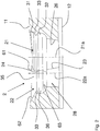
Fig. 1 eine Draufsicht auf eine Lochausbildung in einer Knochenplatte, -
Fig. 2 eine Schnittansicht der Lochausbildung, -
Fig. 3 eine perspektivische Darstellung der Lochausbildung, -
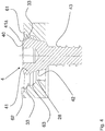
Fig. 4 eine Knochenschraube im Eingriff mit einer Lochausbildung, -
Fig. 5 eine zweite Ausführungsform einer Knochenplatte in perspektivischer Darstellung, -
Fig. 6 eine Schnittansicht der Lochausbildung, -
Fig. 7 eine Seitenansicht der Lochausbildung, und -
Fig. 8 eine Knochenschraube im Eingriff mit einer Lochausbildung, zusammen mit einer Ausschnittsvergrößerung. - Die Figuren zeigen das Stück einer Knochenplatte, die aus einem länglichen Plattenkörper 1 aus einem ersten, gewebeverträglichen, steifen Material besteht und in den eine Reihe von Lochausbildungen angebracht sind, von denen eine Lochausbildung 2 dargestellt ist. Der Plattenkörper 1 kann außer länglich auch oval, rund oder mehreckig ausgebildet oder von seiner Form her der jeweiligen Anwendung angepasst sein.
- Als gewebeverträgliches Material werden beispielsweise Metalle und deren Legierungen verstanden, wie diese üblicherweise zur Herstellung von Implantaten verwendet werden. Bevorzugte Metalle umfassen Titan in jeder Form, vorzugsweise auch dessen Legierungen TiAl6V4 und TiCp..
- Auch Stähle, wie beispielsweise Implantatestahl, beispielsweise die Legierung 1.4441 sind vorteilhaft verwendbar.
- Eine weitere Materialklasse umfasst hierfür auch resorbierbare Materialien, wie beispielsweise Magnesium oder PLA. PLA ist ein biokompatibler und resorbierbarer Kunststoff aus chemisch aneinander gebundenen Milchsäuremolekülen, der wie auch andere resorbierbare Kunststoffe verwendet werden kann.
- Als steif wird eine Knochenplatte dann angesehen, wenn diese konstruktiv die für ihre vorgesehene Verwendung und Einsatzzweck nötige Steifigkeit zur Verfügung stellt. Dies kann je nach verwendetem gewebeverträglichen Material durch die Dicke und Breite der Platte sichergestellt werden und liegt üblicherweise im Bereich fachmännischen Handelns.
- So sind beispielsweise Knochenplatten für kleine und weniger belastete Körperpartien, wie beispielsweise Hand- und Fußknochen dünner und häufig weniger breit als Knochenplatten der größeren und stärker belasteten Partien, wie beispielsweise bei Teilen des Unter- und des Oberschenkels.
- Die Knochenplatte weist eine Oberseite 11 und eine Unterseite 12 auf, die gewöhnlich parallel zur Plattenebene verlaufen, wobei die Unterseite 12 dem zu fixierenden Knochen benachbart ist. Die Lochausbildungen 2 sind entlang der Längsachse des länglichen Plattenkörpers 1 aufgereiht und bestehen aus zwei stufig ausgebildeten Rundlöchern, 21 und 22, die sich quer zur Plattenebene erstrecken und deren Achsen 21a, 22a die Längsachse der Knochenplatte schneiden. Der kleinste Durchmesser des ersten Rundlochs 21 ist größer als der kleinste Durchmesser des zweiten Rundlochs 22 und der Abstand der beiden Achsen 21a und 22a voneinander ist kleiner als der kleinste Durchmesser des ersten Rundlochs 21.
- Durch die Überschneidung der Löcher 21, 22 ergeben sich Kanten 23, 24, welche die Bereiche der Rundlöcher gegeneinander abgrenzen und einen Durchlass für den relativ dünnen Schraubschaft einer Knochenschraube freilassen, wenn bei der Schrägstellung einer Knochenschraube diese von einem Rundloch in das andere Rundloch hineinreicht. Die Umfangswinkel der Wandlaibungen der Rundlöcher 21, 22 betragen ca. 250° des größeren Loches und ca. 220° des kleineren Loches. Variationen um 10° kleiner und 20° größer sind möglich.
- Infolge der Stufigkeit der Rundlöcher 21, 22 kann man eine obere Region 25 und eine untere Region 26 des Rundloches 21 und eine obere Region 27 sowie eine untere Region 28 des Rundlochs 22 unterscheiden.
- Die oberen Regionen 25 und 27 sind schüsselförmig ausladend gestaltet, während die unteren Regionen 26 und 28 Mantelflächen mit geraden Mantellinien bilden. Die oberen Regionen 25 und 27 weisen größere Durchmesser gegenüber den unteren Regionen 26 und 28 auf. Die untere Region 26 bildet einen kegelstumpfförmigen Abschnitt, der sich zur Unterseite des Plattenkörpers 1 hin verjüngt. Die untere Region 28 ist zylindrisch ausgebildet, sie kann aber auch kegelstumpfförmig ausgebildet sein.
- Während die beiden oberen Regionen 25 und 27 der beiden Rundlöcher 21, 22 insgesamt schüsselförmig gestaltet sind, zieht sich, ausgehend von den Lochwandungen, eine radiale Rippe 33 in einer Ebene um die Lochausbildung 2 herum. Die Rippe 33 ist als umlaufender Steg ausgebildet und weist einen keilförmigen Querschnitt auf, der sich zur Mitte des jeweiligen Rundloches hin verjüngt. In der Draufsicht erscheint die Rippe 33 einer Acht ähnlich zu sein.
- Während die Rippe 33 gleichmäßig herumlaufen kann, wird für den am größeren Rundloch angebrachten Rippenteil ein Grat 61 parallel zur Ebene der Rippe 33 am Außenrand des größeren Rundlochs 21 angeordnet, wodurch sich eine Kante 24 zum zweiten Rundloch 22 hin bildet. Ausgehend von der Längsachse des Plattenkörpers 1 nimmt die Höhe des Grates 61 zum Rand des Plattenkörpers 1 hin zu, wie am besten aus dem Vergleich der
Fig. 4 mitFig. 3 hervorgeht. Zwischen dem Grat 61 und der Rippe 33 wird eine Gangführung gebildet, die den Eingriff des Gewindes 41 der Kopfschraube 40 begünstigt. - Jedes der beiden Rundlöcher 21, 22 ist in drei Abschnitte unterteilt: Das größeren Rundloch 21 weist oberhalb der Rippe 33 einen oberen, rundkehlförmigen Abschnitt 31 mit, oder auch ohne Grat 61 auf, und unterhalb der Rippe 33 sind ein mittlerer, rundkehlförmiger Abschnitt 36 und ein unterer, kegelstumpfförmiger Abschnitt 26 vorgesehen. Das kleinere Rundloch 22 umfasst einen oberen Abschnitt 35 mit Einführungsschräge 62, einen mittleren Abschnitt 36 mit einer geneigt-abgerundeten Fläche 63 unterhalb der Ebene der Rippe 33, und einen unteren Abschnitt 28, der vorzugsweise zylindrisch ausgebildet ist, aber auch konisch sein kann.
- Die Knochenplatte ist zur Zusammenwirkung mit wenigstens zweierlei Arten von Knochenschrauben ausgebildet. Die zweite Art weist einen Knochenschraubenkopf mit teilsphärischer Unterseite auf und kann sich mit der Kopfunterseite an der geneigt-abgerundeten Fläche 63 der Knochenplatte abstützen. Dabei ist auch Schrägstellung der Schraubenachse gegenüber der Plattenebene möglich, und zwar sowohl in Längsrichtung als auch (im geringen Maße) in Querrichtung zur Knochenplatte. Ermöglicht wird dies durch den Abstand der Kanten 23 voneinander, der größer ist als der Durchmesser des Schraubschaftes der Knochenschraube.
- Die erste Art von anwendbarer Knochenschraube 4 ist in
Fig. 4 dargestellt. Diese Knochenschraube 4 weist einen Schraubkopf 40 mit Inneneingriff und mit als Außengewinde ausgestaltetem Gewinde 41 am oberen Ende sowie konischer als Stützfläche ausgebildeter Sitzfläche 42 am unteren Ende auf, deren Konusneigung der Konusneigung der unteren Region 26 des größeren Rundloches 21 entspricht. Das Gewinde 41 kann zylindrisch sein, es wird jedoch konisches Gewinde bevorzugt. - Die Konusneigung der unteren Region 26 des größeren Rundloches 21 sowie die Konusneigung der konischen Sitzfläche 42 am unteren Ende des Schraubkopfs 40 der Knochenschraube weist einen Winkel relativ zur Längs- oder Symmetrieachse jeweils der Knochenschraube oder des Rundlochs 21 im Bereich von 3 bis 30° auf. Bevorzugt liegt dieser Konuswinkel in einem Bereich von 6 bis 20° und am bevorzugtesten in einem Bereich von 8 bis 12°. Eine besonderst bevorzugte Bauform hat sich mit einem Konuswinkel von etwa 10° mit hohen Dauerfestigkeitswerten und guter Lösbarkeit der Verbindung zwischen Knochenschraube und Knochenplatte sehr bewährt.
- In einem Winkelbereich von etwa 8 bis 12° werden sehr gute Stabilitätswerte gegenüber dem Verkippen der Knochenschraube relativ zur Knochenplatte bei gleichzeitig nur moderater Selbsthemmung bereitgestellt.
- An den Schraubkopf 40 schließt sich ein Schraubschaft 43 an, der dazu bestimmt ist, in einem zu fixierenden Knochenelement verankert zu werden. Die umlaufende Rippe 33 erstreckt sich in einer Ebene, vorzugsweise parallel zur Plattenebene, während sich das Gewinde 41 entlang von Schraubflächen erstreckt, die naturgemäß schräg gegenüber der Ebene der radialen Rippe 33 verlaufen, und zwar auch dann, wenn die Knochenschraube 4 bestimmungsgemäß parallel oder gleichlaufend mit der Achse 21a des Rundloches 21 verschraubt wird. Dabei erfolgt gegenseitige Formanpassung zwischen den Gewindegängen und der Rippe 33. In dieser Hinsicht ist der Grat 61 nützlich, da er ein Gegenlager für das Gewinde des Schraubkopfes bietet.
- Die gegenseitige Formanpassung setzt eine gewisse Nachgiebigkeit des (ersten) Materials der Knochenplatte wenigstens im Bereich der radialen Rippe 33 und/oder des (zweiten) Materials der Knochenschraube wenigstens im Bereich des Gewindes 41 voraus. Es wird bevorzugt, das (zweite) Material der Knochenschraube härter als das (erste) Material der Knochenplatte zu machen und auch eine Form mit einem größeren Widerstandsmoment für das Gewinde 41 gegenüber dem der Rippe 33 zu wählen. Auf diese Weise passt sich die "weichere", in einer Ebene liegende Rippe weitgehend der Eingriffsschraubwindung des Gewindes 41 an, wenn das Fixationssystem bestimmungsgemäß angewendet wird. Dennoch liegt es auch im Rahmen der Erfindung, dass mindestens im Bereich der radialen Rippe 33 und des Gewindes 41 das erste und zweite Material gleiche Härten aufweisen.
- Hierdurch können sowohl für die Knochenschrauben als auch für die Knochenplatte das gleiche Material verwendet werden und korrosive Effekte im Bereich und in der Nähe der Kontaktstellen von Knochenschraube mit Knochenplatte sicher vermieden werden.
- Im Zusammenhang mit der dargestellten Knochenplatte kann die Knochenschraube 4 zur gegenseitigen Annährung und zum Zusammenpressen von Knochenfragmenten benutzt werden. Hierzu wird die Knochenschraube 4 mit ihrer Achse parallel zur Achse 22a im Bereich des Rundloches 22 angesetzt. Sobald der untere Rand der konischen Sitzfläche 42 die Einführungsschräge 62 des kleineren Rundloches 22 erreicht, erfolgt beim Eindrehen der Schraube eine seitliche Kraft auf den Schraubkopf 40, was zu einer Verschiebung des zu fixierenden Knochenfragments relativ zu der Knochenplatte führt. Wenn demnach ein Knochenfragment mit der Knochenplatte bereits fest verbunden ist, wird dieses Knochenfragment gegen das zu fixierende Knochenfragment geschoben, wie es erwünscht ist.
- Es wird darauf hingewiesen, dass wegen des großen Umfangwinkels der Konusfläche der unteren Region 26, die im Bereich von 250 ° bis 290° liegt, bei festsitzendem Schraubkopf 40 eine genügend starke Verbindung zwischen dem Plattenkörper 1 und der Knochenschraube 4 hergestellt wird, da nach gegenseitiger Deformation die umlaufende Rippe 33 und Eingriffsschraubwindung genügend elastische Spannkraft entwickeln, um die konischen Flächen bei 26 und 42 aufeinandergepresst zu halten.
- Mit
Fig. 5 - 8 ist eine weitere besonders bevorzugte Ausführungsform der Knochenplatte dargestellt, wobei die gleichen Bezugszeichen für sich entsprechende Teile verwendet werden. - Der hauptsächliche Unterschied besteht in der Ausbildung der umlaufenden radialen Rippe 33. Diese ist im Bereich des kleineren Rundlochs 22 teilweise weggeschnitten, um eine geneigt-abgerundete Gleitfläche 35a und eine Übergangsfläche 35b zu schaffen, die zur Führung des Kopfes einer Knochenschraube mit teilsphärischer Unterseite des Kopfes oder zur Führung der Schraube mit konischer Sitzfläche 42 dienlich sind. Es wird eine Restrippe 37 gebildet, die auf volle Größe der Rippe 33 im Bereich des größeren Rundloches 21 ansteigt. Die verbleibende Randkante 34 erstreckt sich um weniger als 180° und erlaubt so die seitliche Einführung von Knochenschrauben vom kleineren Rundloch 22 in das größere Rundloch 21.
- Die Rippe 33 hat einen keilförmigen Querschnitt mit einer zur Lochmitte geneigten Oberseite und einer Unterseite parallel zur Plattenebene. Auf diese Weise ist das Widerstandsmoment der Rippe 33 bedeutend kleiner als das Widerstandsmoment der Schraubwindung im Eingriff mit der Rippe, die Rippe 33 also nachgiebiger selbst dann, wenn die Materialien von Rippe und Schraubwindung von gleicher Härte sind. Eine geringere Härte der Rippe 33 wird jedoch zu Zwecken der Formanpassung bevorzugt.
- Mit der Erfindung wird ein Fixationssystem für Knochen mit Knochenplatte und Knochenschrauben geschaffen, bei dem Knochenschrauben mit Rundkopf im unterschiedlichen Schrägwinkel zur Knochenplatte gesetzt werden können. Ferner ermöglicht das Fixationssystem bei der Anwendung von Knochenschrauben mit Kegelkopf die Relativverschiebung zwischen zu fixierendem Knochenfragment und Knochenplatte, was es dem Operateur ermöglicht, Knochenfragmente bei deren Fixierung gegeneinander zu verschieben.
Claims (13)
- Fixationssystem mit Knochenplatte und Knochenschrauben, um Teile eines gebrochenen oder geschädigten Knochens zu fixieren,
wobei die Knochenplatte umfasst:- einen vorzugsweise länglichen Plattenkörper (1), der eine Plattenebene und eine Längsachse bestimmt und aus einem ersten, insbesondere gewebeverträglichen, vorzugsweise steifen Material, besteht,- Lochausbildungen (2) quer zur Plattenebene, die aus einem ersten Rundloch (21) und einem zweiten Rundloch (22) bestehen, welche sich unter Bildung von Kanten (23,24) schneiden und eine Schraubeneinführungsseite sowie eine Schraubenaustrittsseite besitzen, wobei das erste Rundloch (21) eine konische Sitzfläche an der Schraubenaustrittsseite aufweist, und- eine radiale Rippe (33) in jedem der Rundlöcher, die sich in einer Ebene nahe der Schraubeneinführungsseite zur Rundlochmitte hin erstreckt,wobei die Knochenschrauben (4) jeweils umfassen:- einen Schraubkopf (40) aus einem zweiten, steifen Material mit im oberen Bereich des Kopfes angebrachtem Gewinde (41) und im unteren Bereich angebrachter, konischer Sitzfläche (42) sowie- einen Schraubenschaft (43), undwobei bei der Zusammenarbeit von Gewinde (41) und radialer Rippe (33) eine Deformation erfolgt, die eine gegenseitige Anpassung der Rippe (33) und Eingriffsgewindegang (41a) zur Folge hat. - Fixationssystem nach Anspruch 1,
wobei die Form und Härte der radialen Rippe (33) eine größere Nachgiebigkeit der Rippe (33) gegenüber dem Eingriffsgewindegang (41a) der Knochenschraube (4) zur Folge hat. - Fixationssystem nach Ansprüchen 1 bis 2,
wobei die radiale Rippe (33) von den Rundlochwandungen beider Rundlöcher (21,22) ausgeht und um diese vollständig herumführt. - Fixationssytem nach Anspruch 3,
wobei die umlaufende, radiale Rippe (33) im Bereich des zweiten Rundlochs (22) reduziert ist, um eine geneigt-abgerundete Gleitfläche (35a) und eine Übergangsfläche (35b) zu bilden - Fixationssytem nach Ansprüchen 3 oder 4,
wobei die umlaufende Rippe (33) im zweiten Rundloch (22) zur Oberseite (11) der Knochenplatte hin mit Einführungsschräge verläuft. - Fixationssystem nach einem der Ansprüche 1 bis 5,
wobei das erste Rundloch (21) größer als das zweite Rundloch (22) ist und umfasst:- eine obere Region (25) in Schüsselform und mit einem zugehörigen Abschnitt der radialen Rippe (33) sowie- eine untere Region (26) mit kegelstumpfförmiger Ausbildung und kleinerem Durchmesser gegenüber dem Durchmesser der oberen Region. - Fixationssystem nach Anspruch 6,
wobei das zweite, kleinere Rundloch (22) umfasst:- eine obere Region (27) in Schüsselform und mit einem zugehörigen Abschnitt der radialen Rippe (33) sowie- eine untere Region (28) mit einer zylindrischen oder konischen Fläche, deren Durchmesser kleiner ist als der Durchmesser der oberen Region. - Fixationssystem nach Anspruch 6 oder 7,
wobei die obere Region (25) des ersten, größeren Rundlochs (21) durch die Rippe (33) in einen oberen, rundkehlförmigen Abschnitt (31) oberhalb der Rippe (33) und in einen mittleren, rundkehlförmigen Abschnitt (36) unterhalb der Rippe (33) unterteilt ist und die untere Region (26) des größeren Rundlochs (21) als ein unterer, kegelstumpfförmiger Abschnitt ausgebildet ist, der sich zur Unterseite (12) des Plattenkörpers (1) hin verjüngt und dessen größter Durchmesser kleiner als der Durchmesser des oberen oder mittleren Abschnitts (31,32) ist. - Fixationssystem nach Anspruch 8,
wobei die obere Region (27) des zweiten, kleineren Rundloches (22) einen oberen Abschnitt (35) mit Einführungsschräge (62) aufweist und einen mittleren Abschnitt (36) mit einer geneigt-abgerundeter Fläche (63) unterhalb der Ebene der Rippe (33) besitzt. - Fixationssytem nach einem der Ansprüche 1 bis 9 wobei die Rippe (33) einen keilförmigen Querschnitt aufweist.
- Knochenplatte für ein Fixationssystem nach einem der vorstehenden Ansprüche wobei die Knochenplatte umfasst:
Einen Plattenkörper (1), der eine Plattenebene und eine Längsachse bestimmt, Lochausbildungen (2) quer zur Plattenebene, die aus einem ersten Rundloch (21) und einem zweiten Rundloch (22) bestehen, welche sich unter Bildung von Kanten (23,24) schneiden und eine Schraubeneinführungsseite sowie eine Schraubenaustrittsseite besitzen, wobei das erste Rundloch (21) eine konische Sitzfläche (26) an der Schraubenaustrittsseite aufweist, und eine radiale Rippe (33) in wenigstens einem der Rundlöcher, die sich in einer Ebene nahe der Schraubeneinführungsseite zur Rundlochmitte hin erstreckt, wobei um beide Rundlöcher herum eine radiale Rippe vorgesehen ist, die von der Lochwandung ausgeht und sich in einer Ebene nahe der Schraubeneinführungsseite zur Rundlochmitte hin erstreckt. - Knochenplatte nach einem der vorstehenden Ansprüche,
wobei das erste Rundloch (21) größer als das zweite Rundloch (22) ist und umfasst:
eine obere Region (25) in Schüsselform und mit einem zugehörigen Abschnitt der radialen Rippe (33), sowie eine untere Region (26) mit kegelstumpfförmiger Ausbildung und kleinerem Durchmesser gegenüber dem Durchmesser der oberen Region. - Knochenplatte nach dem vorstehenden Anspruch,
wobei das zweite, kleinere Rundloch (22) umfasst: eine obere Region (27) in Schüsselform und mit einem zugehörigen Abschnitt der radialen Rippe (33) sowie eine untere Region (28) mit einer zylindrischen oder konischen Fläche, deren Durchmesser kleiner ist als der Durchmesser der oberen Region.
Applications Claiming Priority (3)
| Application Number | Priority Date | Filing Date | Title |
|---|---|---|---|
| DE102010025702.8A DE102010025702B4 (de) | 2010-06-30 | 2010-06-30 | Fixationssystem für Knochen mit Knochenplatte und Knochenschrauben |
| PCT/EP2011/003112 WO2012000627A1 (de) | 2010-06-30 | 2011-06-24 | Fixationssystem für knochen |
| EP11730209.1A EP2588015B1 (de) | 2010-06-30 | 2011-06-24 | Fixationssystem für knochen |
Related Parent Applications (2)
| Application Number | Title | Priority Date | Filing Date |
|---|---|---|---|
| EP11730209.1A Division-Into EP2588015B1 (de) | 2010-06-30 | 2011-06-24 | Fixationssystem für knochen |
| EP11730209.1A Division EP2588015B1 (de) | 2010-06-30 | 2011-06-24 | Fixationssystem für knochen |
Publications (2)
| Publication Number | Publication Date |
|---|---|
| EP3081180A1 EP3081180A1 (de) | 2016-10-19 |
| EP3081180B1 true EP3081180B1 (de) | 2020-10-21 |
Family
ID=44503678
Family Applications (2)
| Application Number | Title | Priority Date | Filing Date |
|---|---|---|---|
| EP16173279.7A Active EP3081180B1 (de) | 2010-06-30 | 2011-06-24 | Fixationssystem für knochen |
| EP11730209.1A Active EP2588015B1 (de) | 2010-06-30 | 2011-06-24 | Fixationssystem für knochen |
Family Applications After (1)
| Application Number | Title | Priority Date | Filing Date |
|---|---|---|---|
| EP11730209.1A Active EP2588015B1 (de) | 2010-06-30 | 2011-06-24 | Fixationssystem für knochen |
Country Status (7)
| Country | Link |
|---|---|
| EP (2) | EP3081180B1 (de) |
| DE (1) | DE102010025702B4 (de) |
| DK (1) | DK2588015T3 (de) |
| ES (2) | ES2606560T3 (de) |
| PL (1) | PL2588015T3 (de) |
| PT (1) | PT2588015T (de) |
| WO (1) | WO2012000627A1 (de) |
Families Citing this family (12)
| Publication number | Priority date | Publication date | Assignee | Title |
|---|---|---|---|---|
| US20100256687A1 (en) | 2009-04-01 | 2010-10-07 | Merete Medical Gmbh | Fixation Device and Method of Use for a Ludloff Osteotomy Procedure |
| DE102009016394B4 (de) | 2009-04-07 | 2016-02-11 | Merete Medical Gmbh | Vorrichtung zur winkelstabilen Fixation und Kompression einer Bruchstelle bzw. Osteotomie an einem Knochen |
| ES2573811T3 (es) | 2009-12-22 | 2016-06-10 | Merete Medical Gmbh | Sistema de placa ósea para la osteosíntesis |
| DE202011051165U1 (de) | 2011-08-31 | 2011-11-14 | Merete Medical Gmbh | Anatomisch angepasste, plantare Knochenplatte sowie Knochenplattensystem |
| DE102012103894B4 (de) | 2012-05-03 | 2016-10-27 | Merete Medical Gmbh | Knochenplattensystem für Osteosynthese |
| US9545276B2 (en) | 2013-03-15 | 2017-01-17 | Aristotech Industries Gmbh | Fixation device and method of use for a lapidus-type plantar hallux valgus procedure |
| USD745162S1 (en) | 2014-01-27 | 2015-12-08 | Merete Medical Gmbh | Bone plate |
| MX2017010834A (es) | 2015-02-26 | 2017-12-07 | Medartis Holding Ag | Placa de hueso y equipo quirurgico para fijar fragmentos de hueso. |
| US10687873B2 (en) | 2016-08-17 | 2020-06-23 | Globus Medical Inc. | Stabilization systems |
| US11197701B2 (en) | 2016-08-17 | 2021-12-14 | Globus Medical, Inc. | Stabilization systems |
| DE102021202281A1 (de) | 2021-03-09 | 2022-09-15 | Karl Leibinger Medizintechnik Gmbh & Co. Kg | Verankerbare Implantatanordnung |
| DE102022106581A1 (de) | 2022-03-21 | 2023-09-21 | Medical Magnesium GmbH | System zur Osteosynthese mit Knochenplatte und Knochenanker aus Magnesiumlegierungen |
Family Cites Families (13)
| Publication number | Priority date | Publication date | Assignee | Title |
|---|---|---|---|---|
| EP0760632B1 (de) * | 1995-03-27 | 2000-09-13 | Synthes AG, Chur | Knochenplatte |
| CA2230058C (en) * | 1995-09-06 | 2005-03-29 | Synthes (U.S.A.) | Bone plate |
| DE19858889B4 (de) * | 1998-12-19 | 2008-08-07 | Wolter, Dietmar, Prof. Dr.Med. | Fixationssystem für Knochen |
| ATE270526T1 (de) | 1999-03-09 | 2004-07-15 | Synthes Ag | Knochenplatte mit konischen gewinden |
| AU756487B2 (en) | 1999-03-09 | 2003-01-16 | Synthes Gmbh | Bone plate |
| WO2001054601A1 (de) | 2000-01-27 | 2001-08-02 | Synthes Ag Chur | Knochenplatte |
| US7695472B2 (en) * | 2003-03-26 | 2010-04-13 | Swiss Orthopedic Solutions Sa | Locking bone plate |
| EP1649819A1 (de) * | 2004-10-19 | 2006-04-26 | Christian Maier | Knochenplatte |
| FR2880929B1 (fr) * | 2005-01-17 | 2007-03-30 | Didier Roux | Systeme de fixation du type par vis imperdable |
| CN101272743B (zh) * | 2005-07-25 | 2011-01-26 | 史密夫和内修有限公司 | 使用多轴式板的系统 |
| ATE404129T1 (de) * | 2006-05-26 | 2008-08-15 | Aap Implantate Ag | Knochenplatte |
| US20080234749A1 (en) * | 2007-01-26 | 2008-09-25 | Zimmer Technology, Inc. | Bone plate providing threaded locking head screw capture |
| AR061999A1 (es) * | 2007-07-18 | 2008-08-10 | Pizzicara Mario Angel | Placa bloqueada de orificios combinados, control de estabilidad y doble angulacion, para union de huesos fracturados |
-
2010
- 2010-06-30 DE DE102010025702.8A patent/DE102010025702B4/de active Active
-
2011
- 2011-06-24 PT PT117302091T patent/PT2588015T/pt unknown
- 2011-06-24 ES ES11730209.1T patent/ES2606560T3/es active Active
- 2011-06-24 ES ES16173279T patent/ES2841375T3/es active Active
- 2011-06-24 EP EP16173279.7A patent/EP3081180B1/de active Active
- 2011-06-24 PL PL11730209T patent/PL2588015T3/pl unknown
- 2011-06-24 EP EP11730209.1A patent/EP2588015B1/de active Active
- 2011-06-24 WO PCT/EP2011/003112 patent/WO2012000627A1/de active Application Filing
- 2011-06-24 DK DK11730209.1T patent/DK2588015T3/en active
Non-Patent Citations (1)
| Title |
|---|
| None * |
Also Published As
| Publication number | Publication date |
|---|---|
| EP2588015B1 (de) | 2016-11-16 |
| EP2588015A1 (de) | 2013-05-08 |
| WO2012000627A1 (de) | 2012-01-05 |
| DE102010025702A1 (de) | 2012-01-05 |
| DK2588015T3 (en) | 2017-02-20 |
| ES2841375T3 (es) | 2021-07-08 |
| PT2588015T (pt) | 2017-02-21 |
| EP3081180A1 (de) | 2016-10-19 |
| PL2588015T3 (pl) | 2017-05-31 |
| ES2606560T3 (es) | 2017-03-24 |
| DE102010025702B4 (de) | 2016-08-18 |
Similar Documents
| Publication | Publication Date | Title |
|---|---|---|
| EP3081180B1 (de) | Fixationssystem für knochen | |
| EP2584983B1 (de) | Knochenplatte sowie fixationssystem mit knochenplatte | |
| EP0291632B1 (de) | Kleinknochenplatte, insbesondere für die Versorgung von Frakturen des Schädel- und Gesichtsskeletts oder dergleichen | |
| EP1568329B1 (de) | Knochenverankerungselement | |
| EP1800615B1 (de) | Knochenplatte | |
| DE102005004841B4 (de) | Osteosyntheseplatte mit einer Vielzahl von Bohrungen zur Aufnahme von Knochenschrauben | |
| EP0487830B1 (de) | Korrekturimplantat für die menschliche Wirbelsäule | |
| DE4343117C2 (de) | Fixationssystem für Knochen | |
| DE202011106835U1 (de) | Knochenplatte | |
| DE3027148A1 (de) | Einrichtung mit einer platte und zu deren befestigung an einem knochen dienenden schrauben | |
| EP2844169B1 (de) | Knochenplattensystem für osteosynthese | |
| EP1476098A1 (de) | Zwischenwirbelimplantat | |
| EP2741701A1 (de) | System aus einer knochenplatte und einer knochenschraube | |
| WO2016142502A1 (de) | Knochenplatte mit einer knochenschraube | |
| WO2006072284A1 (de) | Variabel winkelstabile schraubverbindung für die osteosynthese | |
| EP1859752B1 (de) | Knochenplatte | |
| DE102010025000B4 (de) | Knochenplatte | |
| WO2008003313A2 (de) | Osteosynthesisches fixationssystem | |
| EP2801330A1 (de) | Knochenplatte mit einem Inlay und Verfahren zum Herstellen einer Knochenplatte | |
| DE102010064626B3 (de) | Knochenplatte | |
| EP3501437A1 (de) | Knochenplatte und verfahren zum herstellen einer knochenplatte | |
| AT508196B1 (de) | Fixierungssystem für knochen mit konvexem bohrloch |
Legal Events
| Date | Code | Title | Description |
|---|---|---|---|
| PUAI | Public reference made under article 153(3) epc to a published international application that has entered the european phase |
Free format text: ORIGINAL CODE: 0009012 |
|
| 17P | Request for examination filed |
Effective date: 20160607 |
|
| AC | Divisional application: reference to earlier application |
Ref document number: 2588015 Country of ref document: EP Kind code of ref document: P |
|
| AK | Designated contracting states |
Kind code of ref document: A1 Designated state(s): AL AT BE BG CH CY CZ DE DK EE ES FI FR GB GR HR HU IE IS IT LI LT LU LV MC MK MT NL NO PL PT RO RS SE SI SK SM TR |
|
| RIC1 | Information provided on ipc code assigned before grant |
Ipc: A61B 17/00 20060101ALI20200403BHEP Ipc: A61B 17/80 20060101AFI20200403BHEP Ipc: A61B 17/86 20060101ALI20200403BHEP |
|
| GRAP | Despatch of communication of intention to grant a patent |
Free format text: ORIGINAL CODE: EPIDOSNIGR1 |
|
| STAA | Information on the status of an ep patent application or granted ep patent |
Free format text: STATUS: GRANT OF PATENT IS INTENDED |
|
| INTG | Intention to grant announced |
Effective date: 20200515 |
|
| RIN1 | Information on inventor provided before grant (corrected) |
Inventor name: BARTSCH, THOMAS Inventor name: PAULIN, THOMAS Inventor name: ALEMU, BRUKE SEYOUM Inventor name: FISCHER, HANS-JOACHIM |
|
| GRAS | Grant fee paid |
Free format text: ORIGINAL CODE: EPIDOSNIGR3 |
|
| GRAA | (expected) grant |
Free format text: ORIGINAL CODE: 0009210 |
|
| STAA | Information on the status of an ep patent application or granted ep patent |
Free format text: STATUS: THE PATENT HAS BEEN GRANTED |
|
| AC | Divisional application: reference to earlier application |
Ref document number: 2588015 Country of ref document: EP Kind code of ref document: P |
|
| AK | Designated contracting states |
Kind code of ref document: B1 Designated state(s): AL AT BE BG CH CY CZ DE DK EE ES FI FR GB GR HR HU IE IS IT LI LT LU LV MC MK MT NL NO PL PT RO RS SE SI SK SM TR |
|
| REG | Reference to a national code |
Ref country code: GB Ref legal event code: FG4D Free format text: NOT ENGLISH |
|
| REG | Reference to a national code |
Ref country code: CH Ref legal event code: EP |
|
| REG | Reference to a national code |
Ref country code: IE Ref legal event code: FG4D Free format text: LANGUAGE OF EP DOCUMENT: GERMAN |
|
| REG | Reference to a national code |
Ref country code: DE Ref legal event code: R096 Ref document number: 502011016951 Country of ref document: DE |
|
| REG | Reference to a national code |
Ref country code: AT Ref legal event code: REF Ref document number: 1325019 Country of ref document: AT Kind code of ref document: T Effective date: 20201115 |
|
| REG | Reference to a national code |
Ref country code: NL Ref legal event code: MP Effective date: 20201021 |
|
| PG25 | Lapsed in a contracting state [announced via postgrant information from national office to epo] |
Ref country code: PT Free format text: LAPSE BECAUSE OF FAILURE TO SUBMIT A TRANSLATION OF THE DESCRIPTION OR TO PAY THE FEE WITHIN THE PRESCRIBED TIME-LIMIT Effective date: 20210222 Ref country code: RS Free format text: LAPSE BECAUSE OF FAILURE TO SUBMIT A TRANSLATION OF THE DESCRIPTION OR TO PAY THE FEE WITHIN THE PRESCRIBED TIME-LIMIT Effective date: 20201021 Ref country code: NL Free format text: LAPSE BECAUSE OF FAILURE TO SUBMIT A TRANSLATION OF THE DESCRIPTION OR TO PAY THE FEE WITHIN THE PRESCRIBED TIME-LIMIT Effective date: 20201021 Ref country code: NO Free format text: LAPSE BECAUSE OF FAILURE TO SUBMIT A TRANSLATION OF THE DESCRIPTION OR TO PAY THE FEE WITHIN THE PRESCRIBED TIME-LIMIT Effective date: 20210121 Ref country code: FI Free format text: LAPSE BECAUSE OF FAILURE TO SUBMIT A TRANSLATION OF THE DESCRIPTION OR TO PAY THE FEE WITHIN THE PRESCRIBED TIME-LIMIT Effective date: 20201021 Ref country code: GR Free format text: LAPSE BECAUSE OF FAILURE TO SUBMIT A TRANSLATION OF THE DESCRIPTION OR TO PAY THE FEE WITHIN THE PRESCRIBED TIME-LIMIT Effective date: 20210122 |
|
| REG | Reference to a national code |
Ref country code: LT Ref legal event code: MG4D |
|
| PG25 | Lapsed in a contracting state [announced via postgrant information from national office to epo] |
Ref country code: BG Free format text: LAPSE BECAUSE OF FAILURE TO SUBMIT A TRANSLATION OF THE DESCRIPTION OR TO PAY THE FEE WITHIN THE PRESCRIBED TIME-LIMIT Effective date: 20210121 Ref country code: PL Free format text: LAPSE BECAUSE OF FAILURE TO SUBMIT A TRANSLATION OF THE DESCRIPTION OR TO PAY THE FEE WITHIN THE PRESCRIBED TIME-LIMIT Effective date: 20201021 Ref country code: LV Free format text: LAPSE BECAUSE OF FAILURE TO SUBMIT A TRANSLATION OF THE DESCRIPTION OR TO PAY THE FEE WITHIN THE PRESCRIBED TIME-LIMIT Effective date: 20201021 Ref country code: IS Free format text: LAPSE BECAUSE OF FAILURE TO SUBMIT A TRANSLATION OF THE DESCRIPTION OR TO PAY THE FEE WITHIN THE PRESCRIBED TIME-LIMIT Effective date: 20210221 Ref country code: SE Free format text: LAPSE BECAUSE OF FAILURE TO SUBMIT A TRANSLATION OF THE DESCRIPTION OR TO PAY THE FEE WITHIN THE PRESCRIBED TIME-LIMIT Effective date: 20201021 |
|
| PG25 | Lapsed in a contracting state [announced via postgrant information from national office to epo] |
Ref country code: HR Free format text: LAPSE BECAUSE OF FAILURE TO SUBMIT A TRANSLATION OF THE DESCRIPTION OR TO PAY THE FEE WITHIN THE PRESCRIBED TIME-LIMIT Effective date: 20201021 |
|
| REG | Reference to a national code |
Ref country code: ES Ref legal event code: FG2A Ref document number: 2841375 Country of ref document: ES Kind code of ref document: T3 Effective date: 20210708 |
|
| REG | Reference to a national code |
Ref country code: DE Ref legal event code: R097 Ref document number: 502011016951 Country of ref document: DE |
|
| PG25 | Lapsed in a contracting state [announced via postgrant information from national office to epo] |
Ref country code: CZ Free format text: LAPSE BECAUSE OF FAILURE TO SUBMIT A TRANSLATION OF THE DESCRIPTION OR TO PAY THE FEE WITHIN THE PRESCRIBED TIME-LIMIT Effective date: 20201021 Ref country code: EE Free format text: LAPSE BECAUSE OF FAILURE TO SUBMIT A TRANSLATION OF THE DESCRIPTION OR TO PAY THE FEE WITHIN THE PRESCRIBED TIME-LIMIT Effective date: 20201021 Ref country code: SM Free format text: LAPSE BECAUSE OF FAILURE TO SUBMIT A TRANSLATION OF THE DESCRIPTION OR TO PAY THE FEE WITHIN THE PRESCRIBED TIME-LIMIT Effective date: 20201021 Ref country code: LT Free format text: LAPSE BECAUSE OF FAILURE TO SUBMIT A TRANSLATION OF THE DESCRIPTION OR TO PAY THE FEE WITHIN THE PRESCRIBED TIME-LIMIT Effective date: 20201021 Ref country code: RO Free format text: LAPSE BECAUSE OF FAILURE TO SUBMIT A TRANSLATION OF THE DESCRIPTION OR TO PAY THE FEE WITHIN THE PRESCRIBED TIME-LIMIT Effective date: 20201021 Ref country code: SK Free format text: LAPSE BECAUSE OF FAILURE TO SUBMIT A TRANSLATION OF THE DESCRIPTION OR TO PAY THE FEE WITHIN THE PRESCRIBED TIME-LIMIT Effective date: 20201021 |
|
| PLBE | No opposition filed within time limit |
Free format text: ORIGINAL CODE: 0009261 |
|
| STAA | Information on the status of an ep patent application or granted ep patent |
Free format text: STATUS: NO OPPOSITION FILED WITHIN TIME LIMIT |
|
| PG25 | Lapsed in a contracting state [announced via postgrant information from national office to epo] |
Ref country code: DK Free format text: LAPSE BECAUSE OF FAILURE TO SUBMIT A TRANSLATION OF THE DESCRIPTION OR TO PAY THE FEE WITHIN THE PRESCRIBED TIME-LIMIT Effective date: 20201021 |
|
| 26N | No opposition filed |
Effective date: 20210722 |
|
| PG25 | Lapsed in a contracting state [announced via postgrant information from national office to epo] |
Ref country code: AL Free format text: LAPSE BECAUSE OF FAILURE TO SUBMIT A TRANSLATION OF THE DESCRIPTION OR TO PAY THE FEE WITHIN THE PRESCRIBED TIME-LIMIT Effective date: 20201021 |
|
| PG25 | Lapsed in a contracting state [announced via postgrant information from national office to epo] |
Ref country code: SI Free format text: LAPSE BECAUSE OF FAILURE TO SUBMIT A TRANSLATION OF THE DESCRIPTION OR TO PAY THE FEE WITHIN THE PRESCRIBED TIME-LIMIT Effective date: 20201021 |
|
| PG25 | Lapsed in a contracting state [announced via postgrant information from national office to epo] |
Ref country code: MC Free format text: LAPSE BECAUSE OF FAILURE TO SUBMIT A TRANSLATION OF THE DESCRIPTION OR TO PAY THE FEE WITHIN THE PRESCRIBED TIME-LIMIT Effective date: 20201021 |
|
| REG | Reference to a national code |
Ref country code: CH Ref legal event code: PL |
|
| GBPC | Gb: european patent ceased through non-payment of renewal fee |
Effective date: 20210624 |
|
| REG | Reference to a national code |
Ref country code: BE Ref legal event code: MM Effective date: 20210630 |
|
| PG25 | Lapsed in a contracting state [announced via postgrant information from national office to epo] |
Ref country code: LU Free format text: LAPSE BECAUSE OF NON-PAYMENT OF DUE FEES Effective date: 20210624 |
|
| PG25 | Lapsed in a contracting state [announced via postgrant information from national office to epo] |
Ref country code: LI Free format text: LAPSE BECAUSE OF NON-PAYMENT OF DUE FEES Effective date: 20210630 Ref country code: IE Free format text: LAPSE BECAUSE OF NON-PAYMENT OF DUE FEES Effective date: 20210624 Ref country code: GB Free format text: LAPSE BECAUSE OF NON-PAYMENT OF DUE FEES Effective date: 20210624 Ref country code: CH Free format text: LAPSE BECAUSE OF NON-PAYMENT OF DUE FEES Effective date: 20210630 |
|
| PG25 | Lapsed in a contracting state [announced via postgrant information from national office to epo] |
Ref country code: IS Free format text: LAPSE BECAUSE OF FAILURE TO SUBMIT A TRANSLATION OF THE DESCRIPTION OR TO PAY THE FEE WITHIN THE PRESCRIBED TIME-LIMIT Effective date: 20210221 |
|
| PG25 | Lapsed in a contracting state [announced via postgrant information from national office to epo] |
Ref country code: BE Free format text: LAPSE BECAUSE OF NON-PAYMENT OF DUE FEES Effective date: 20210630 |
|
| REG | Reference to a national code |
Ref country code: AT Ref legal event code: MM01 Ref document number: 1325019 Country of ref document: AT Kind code of ref document: T Effective date: 20210624 |
|
| PG25 | Lapsed in a contracting state [announced via postgrant information from national office to epo] |
Ref country code: AT Free format text: LAPSE BECAUSE OF NON-PAYMENT OF DUE FEES Effective date: 20210624 |
|
| PG25 | Lapsed in a contracting state [announced via postgrant information from national office to epo] |
Ref country code: HU Free format text: LAPSE BECAUSE OF FAILURE TO SUBMIT A TRANSLATION OF THE DESCRIPTION OR TO PAY THE FEE WITHIN THE PRESCRIBED TIME-LIMIT; INVALID AB INITIO Effective date: 20110624 Ref country code: CY Free format text: LAPSE BECAUSE OF FAILURE TO SUBMIT A TRANSLATION OF THE DESCRIPTION OR TO PAY THE FEE WITHIN THE PRESCRIBED TIME-LIMIT Effective date: 20201021 |
|
| P01 | Opt-out of the competence of the unified patent court (upc) registered |
Effective date: 20230525 |
|
| PGFP | Annual fee paid to national office [announced via postgrant information from national office to epo] |
Ref country code: FR Payment date: 20230621 Year of fee payment: 13 |
|
| PGFP | Annual fee paid to national office [announced via postgrant information from national office to epo] |
Ref country code: IT Payment date: 20230630 Year of fee payment: 13 Ref country code: ES Payment date: 20230719 Year of fee payment: 13 |
|
| PGFP | Annual fee paid to national office [announced via postgrant information from national office to epo] |
Ref country code: DE Payment date: 20231102 Year of fee payment: 13 |