EP3081074A1 - Système d'entraînement et procédé associé - Google Patents
Système d'entraînement et procédé associé Download PDFInfo
- Publication number
- EP3081074A1 EP3081074A1 EP16165104.7A EP16165104A EP3081074A1 EP 3081074 A1 EP3081074 A1 EP 3081074A1 EP 16165104 A EP16165104 A EP 16165104A EP 3081074 A1 EP3081074 A1 EP 3081074A1
- Authority
- EP
- European Patent Office
- Prior art keywords
- motor
- fluid
- drive system
- belt
- drive
- Prior art date
- Legal status (The legal status is an assumption and is not a legal conclusion. Google has not performed a legal analysis and makes no representation as to the accuracy of the status listed.)
- Granted
Links
- 238000000034 method Methods 0.000 title claims abstract description 13
- 230000026058 directional locomotion Effects 0.000 claims abstract description 3
- 239000012530 fluid Substances 0.000 claims description 106
- 230000033001 locomotion Effects 0.000 claims description 11
- 230000004044 response Effects 0.000 claims description 9
- 230000007423 decrease Effects 0.000 claims description 3
- 230000003247 decreasing effect Effects 0.000 claims description 2
- 230000007246 mechanism Effects 0.000 description 8
- 230000009471 action Effects 0.000 description 5
- 238000012423 maintenance Methods 0.000 description 5
- 239000000463 material Substances 0.000 description 4
- 230000008439 repair process Effects 0.000 description 4
- 230000005540 biological transmission Effects 0.000 description 3
- 230000006870 function Effects 0.000 description 2
- 230000000670 limiting effect Effects 0.000 description 2
- 230000007257 malfunction Effects 0.000 description 2
- 230000036961 partial effect Effects 0.000 description 2
- 230000008569 process Effects 0.000 description 2
- 241001124569 Lycaenidae Species 0.000 description 1
- 229910000831 Steel Inorganic materials 0.000 description 1
- 230000006978 adaptation Effects 0.000 description 1
- 230000004075 alteration Effects 0.000 description 1
- 230000000712 assembly Effects 0.000 description 1
- 238000000429 assembly Methods 0.000 description 1
- 230000004888 barrier function Effects 0.000 description 1
- 239000000446 fuel Substances 0.000 description 1
- 230000004048 modification Effects 0.000 description 1
- 238000012986 modification Methods 0.000 description 1
- 230000000737 periodic effect Effects 0.000 description 1
- 230000001737 promoting effect Effects 0.000 description 1
- 230000002829 reductive effect Effects 0.000 description 1
- 230000001105 regulatory effect Effects 0.000 description 1
- 230000000284 resting effect Effects 0.000 description 1
- 239000011435 rock Substances 0.000 description 1
- 238000012163 sequencing technique Methods 0.000 description 1
- 239000010959 steel Substances 0.000 description 1
Images


Classifications
-
- F—MECHANICAL ENGINEERING; LIGHTING; HEATING; WEAPONS; BLASTING
- F16—ENGINEERING ELEMENTS AND UNITS; GENERAL MEASURES FOR PRODUCING AND MAINTAINING EFFECTIVE FUNCTIONING OF MACHINES OR INSTALLATIONS; THERMAL INSULATION IN GENERAL
- F16H—GEARING
- F16H7/00—Gearings for conveying rotary motion by endless flexible members
- F16H7/08—Means for varying tension of belts, ropes, or chains
- F16H7/10—Means for varying tension of belts, ropes, or chains by adjusting the axis of a pulley
- F16H7/12—Means for varying tension of belts, ropes, or chains by adjusting the axis of a pulley of an idle pulley
- F16H7/1254—Means for varying tension of belts, ropes, or chains by adjusting the axis of a pulley of an idle pulley without vibration damping means
- F16H7/1281—Means for varying tension of belts, ropes, or chains by adjusting the axis of a pulley of an idle pulley without vibration damping means where the axis of the pulley moves along a substantially circular path
-
- A—HUMAN NECESSITIES
- A01—AGRICULTURE; FORESTRY; ANIMAL HUSBANDRY; HUNTING; TRAPPING; FISHING
- A01D—HARVESTING; MOWING
- A01D69/00—Driving mechanisms or parts thereof for harvesters or mowers
- A01D69/002—Driving mechanisms or parts thereof for harvesters or mowers driven by power take-off
-
- A—HUMAN NECESSITIES
- A01—AGRICULTURE; FORESTRY; ANIMAL HUSBANDRY; HUNTING; TRAPPING; FISHING
- A01D—HARVESTING; MOWING
- A01D69/00—Driving mechanisms or parts thereof for harvesters or mowers
- A01D69/03—Driving mechanisms or parts thereof for harvesters or mowers fluid
-
- A—HUMAN NECESSITIES
- A01—AGRICULTURE; FORESTRY; ANIMAL HUSBANDRY; HUNTING; TRAPPING; FISHING
- A01D—HARVESTING; MOWING
- A01D69/00—Driving mechanisms or parts thereof for harvesters or mowers
- A01D69/08—Clutches
-
- A—HUMAN NECESSITIES
- A01—AGRICULTURE; FORESTRY; ANIMAL HUSBANDRY; HUNTING; TRAPPING; FISHING
- A01F—PROCESSING OF HARVESTED PRODUCE; HAY OR STRAW PRESSES; DEVICES FOR STORING AGRICULTURAL OR HORTICULTURAL PRODUCE
- A01F15/00—Baling presses for straw, hay or the like
- A01F15/08—Details
- A01F15/0841—Drives for balers
-
- F—MECHANICAL ENGINEERING; LIGHTING; HEATING; WEAPONS; BLASTING
- F16—ENGINEERING ELEMENTS AND UNITS; GENERAL MEASURES FOR PRODUCING AND MAINTAINING EFFECTIVE FUNCTIONING OF MACHINES OR INSTALLATIONS; THERMAL INSULATION IN GENERAL
- F16H—GEARING
- F16H7/00—Gearings for conveying rotary motion by endless flexible members
- F16H7/08—Means for varying tension of belts, ropes, or chains
- F16H2007/0802—Actuators for final output members
- F16H2007/0812—Fluid pressure
-
- F—MECHANICAL ENGINEERING; LIGHTING; HEATING; WEAPONS; BLASTING
- F16—ENGINEERING ELEMENTS AND UNITS; GENERAL MEASURES FOR PRODUCING AND MAINTAINING EFFECTIVE FUNCTIONING OF MACHINES OR INSTALLATIONS; THERMAL INSULATION IN GENERAL
- F16H—GEARING
- F16H7/00—Gearings for conveying rotary motion by endless flexible members
- F16H7/08—Means for varying tension of belts, ropes, or chains
- F16H2007/0863—Finally actuated members, e.g. constructional details thereof
- F16H2007/0865—Pulleys
-
- F—MECHANICAL ENGINEERING; LIGHTING; HEATING; WEAPONS; BLASTING
- F16—ENGINEERING ELEMENTS AND UNITS; GENERAL MEASURES FOR PRODUCING AND MAINTAINING EFFECTIVE FUNCTIONING OF MACHINES OR INSTALLATIONS; THERMAL INSULATION IN GENERAL
- F16H—GEARING
- F16H7/00—Gearings for conveying rotary motion by endless flexible members
- F16H7/08—Means for varying tension of belts, ropes, or chains
- F16H2007/0876—Control or adjustment of actuators
- F16H2007/0885—Control or adjustment of actuators the tension being a function of engine running condition
-
- F—MECHANICAL ENGINEERING; LIGHTING; HEATING; WEAPONS; BLASTING
- F16—ENGINEERING ELEMENTS AND UNITS; GENERAL MEASURES FOR PRODUCING AND MAINTAINING EFFECTIVE FUNCTIONING OF MACHINES OR INSTALLATIONS; THERMAL INSULATION IN GENERAL
- F16H—GEARING
- F16H7/00—Gearings for conveying rotary motion by endless flexible members
- F16H7/08—Means for varying tension of belts, ropes, or chains
- F16H2007/0889—Path of movement of the finally actuated member
- F16H2007/0893—Circular path
Definitions
- a drive system for an agricultural work machine having a primary drive system configured to drive a performance system for performing a crop preparation or handling operation.
- the drive system includes a hydraulic fluid pump having a fluid outlet and a hydraulic motor operatively connected to the fluid outlet of the hydraulic fluid pump, wherein the hydraulic motor includes an output.
- a wheel is operatively connected the output of the hydraulic motor and to the primary drive system. The wheel is configured to be driven by the output of the hydraulic motor.
- a belt is operatively connected to the wheel and to the primary drive system.
- a tensioner is disposed adjacently to the belt, the tensioner being configured to tension the belt as the wheel is driven by the hydraulic motor.
- an agricultural work machine driven by a primary power source to provide a crop preparation or handling operation.
- the work machine includes a performance system and a primary drive system.
- the performance system is configured to perform the crop preparation or handling operation of the work machine.
- the primary drive system is operatively connected to the primary power source and is configured to drive the performance system for the crop preparation or handling operation.
- a secondary drive system is operatively connected to the primary drive system, wherein the secondary drive system includes a belt configured to adjust a condition of the primary drive system.
- the secondary drive system also include a fluid driven motor having an output, configured to be driven in a first direction by a fluid flowing in a first fluid flow direction and driven in a second direction by the fluid flowing in a second fluid flow direction, and a first tensioner disposed adjacently to the belt at a first location.
- the first tensioner is configured to apply a first force to the belt at the first location in response to fluid flowing in the first fluid flow direction.
- the plunger head 20 When the drive cylinder 34 is fully retracted, as shown in FIG. 1 , the plunger head 20 is fully extended to the rear, with the pins 30 and 32 being located such that they lie along a longitudinal central axis of the baling chamber 18. Extension of the cylinder 34 will cause the link 26 to be pivoted upwardly about the pin 32 resulting in the plunger head 20 being retracted to the extent that it uncovers a crop material inlet 40 extending entirely across a region located just in front of a stationary knife (not shown) provided across a forward end 42 of a bottom wall or floor 44 of the baling chamber 18.
- the baling chamber 18 includes a front section 46 of fixed cross section which is joined to a rear section 48, of variable cross section, having opposite side panels which are respectively mounted for swinging horizontally about vertical hinges (not shown) provided at their forward ends.
- a twine tying arrangement (not shown) is provided for wrapping and tying multiple loops of twine about a completed bale.
- a needle yoke arrangement 50 including opposite arms 52, is joined by a cross tube 54.
- the needle yoke arrangement 50 is mounted for vertical pivotal movement about a horizontal transverse axis defined by pivotal connections 56 that connect respective ends of the arms 52 to opposite side locations of rear regions of the fixed front baling chamber section 46.
- the hub 110 is fixedly coupled to a flywheel 112, which in turn is fixedly coupled to a drive shaft 114.
- the drive shaft 114 is operatively connected to the above described systems and subsytems for forming bales, tying bales, and moving the formed bales into and out of the baling chamber 18.
- the flywheel experiences sufficient angular momentum to develop several thousands of pounds of horsepower, which in general terms, is a large amount of torque. Consequently, when the flywheel needs to be slowed and stopped from rotation, a brake apparatus 116, which disposed adjacently to an exterior surface 118 of the flywheel 112, is used to brake the flywheel 112. See FIG. 2 .
- the brake apparatus 116 includes a brake handle 120 which disposed at a location accessible to an operator outside the housing 84. Movement of the brake handle 120 moves a brake pad device 122 into and out of engagement with the surface 118 of the flywheel 112.
- the idler system 140 is an alternative or secondary drive system, in addition to the primary drive system 100 which includes the drive connector 82 which is coupled to the PTO or some other external drive system.
- the idler system 140 is configured to move or adjust the location of the various system components including those described in the above described systems and subsystems for forming bales, tying bales, and moving the formed bales, to repair, maintain, or make adjustments to these and other performance systems of the work machine.
- the idler system 140 therefore, is configured to move the hub 110, the flywheel 112, and the drive shaft 114 in both a clockwise direction and a counter clockwise direction around a longitudinal axis 142 of the drive shaft 114 to repair, adjust, or maintain the baler performance systems.
- the idler system 140 is operatively connected to the bracket 136 for support by the internal frame 130.
- the idler system 140 includes a base 144, which is rigidly coupled to the bracket 136 by one or more connectors 146, and which support a motor 150.
- the motor 150 is fixedly coupled to the base 144 and includes an output drive shaft 152 which extends through the base 144 and to which a first pulley wheel 154 is operatively connected.
- the base 144 in one embodiment, is formed a sheet steel, and includes a "teardrop" shaped planar profile which defines an aperture 156 through which the clutch assembly 108 extends.
- a second pulley wheel 158 is disposed adjacently to the aperture 156 and is fixedly coupled to the clutch assembly 108 and the hub 110.
- the second pulley 158 includes a plurality of apertures 160 which align with corresponding apertures 162 of the clutch assembly 108 and apertures 164 of the hub 110. Connectors (not shown) are received by each of the apertures 160, 162, and 164 to thereby fix the second pulley 158 to the clutch assembly 108 and to the hub 110 such that rotation of the drive shaft 102 moves the pulley 158 and rotational movement of the second pulley 158 moves both the clutch assembly 108 and the hub 110.
- the controller 219 includes an electronic controller configured to control the flow of fluid in response to an input provided by the operator of the baler, either through devices located at the baler or located at a tractor or other vehicle pulling the baler.
- the electronic controller in different embodiments, includes a microcontroller, a microprocessor, dedicated circuitry, or software controlled circuitry configured to provide the directional control of the hub 110 in response to a user input.
- the flow of fluid through the fluid circuit is reversed, such that fluid flow moves from the hydraulic source 212, through the valve 214, along the fluid line 218, and through the valve 222.
- the fluid flow actuates the cylinder 186 to move the rod 232 and the idler pulley 198 into contact with the belt 166.
- the application of the idler pulley 198 applies a tension to the belt 166 at the second location 178 as previously described.
- the fluid flow continues through the port 226, the motor 150, through the port 224, through the valve 220 along the fluid line 216, through the valve 214 and back to the source 212.
- the controller 219 is configured to control the operation of the valves 220 and 222 to control the pressure and/or flow control delivered to the respective hydraulic cylinders 184 and 186.
- the valves 220 and 222 are operatively connected to respective control lines 246 and 248 which transmit signals to respective valves to adjust the fluid flow or pressure in the fluid lines 216 and 218.
- the valves 220 and 222 in different embodiments, are configured to control the amount of tension provided by the pulleys 196 and 198 through the action of the cylinders 184 and 186. In other embodiments, the valves 220 and 222 are not included.
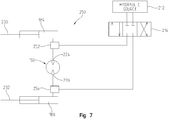
- FIG. 7 illustrates another embodiment of a fluid control circuit 250 operatively connected to the motor 150 and to the hydraulic cylinders 184 and 186.
- each of the hydraulic cylinders includes respective piston rods 230 and 232.
- the hydraulic source 212 is operatively connected to the valve 214 which is configured to provide a flow of fluid to and from the motor 150 over the first fluid line 216, or conduit, and the second fluid line 218, or conduit.
- a first pressure control valve 252 is operatively connected to the port 224 of the motor 150 and a second pressure control valve 254 is operatively connected to the port 226 of the motor 150.
- FIG. 9 illustrates another embodiment of a fluid control circuit 280 operatively connected to the motor 150 of the idler system 260 of FIG. 8 .
- the hydraulic source 212 is operatively connected to the motor 150 and the operation thereof is controlled by the controller 219.
- a valve 282 is operatively connected to the controller 219 for movement of the valve from at least a first position to a second position to control the motor 150.
- the valve 282 is a selectable control valve configured to respond to one or more control signals provided by the controller 219.
- the selectable control valve 282 in different embodiments, is located on a vehicle, such as a tractor, or on a work machine such as a bailer.
Landscapes
- Engineering & Computer Science (AREA)
- General Engineering & Computer Science (AREA)
- Life Sciences & Earth Sciences (AREA)
- Environmental Sciences (AREA)
- Mechanical Engineering (AREA)
- Devices For Conveying Motion By Means Of Endless Flexible Members (AREA)
- Harvester Elements (AREA)
- Transmissions By Endless Flexible Members (AREA)
Applications Claiming Priority (1)
| Application Number | Priority Date | Filing Date | Title |
|---|---|---|---|
| US14/685,805 US9528576B2 (en) | 2015-04-14 | 2015-04-14 | Drive system with hydraulic idler tensioner |
Publications (2)
| Publication Number | Publication Date |
|---|---|
| EP3081074A1 true EP3081074A1 (fr) | 2016-10-19 |
| EP3081074B1 EP3081074B1 (fr) | 2018-06-27 |
Family
ID=55754146
Family Applications (1)
| Application Number | Title | Priority Date | Filing Date |
|---|---|---|---|
| EP16165104.7A Active EP3081074B1 (fr) | 2015-04-14 | 2016-04-13 | Système d'entraînement et procédé associé |
Country Status (4)
| Country | Link |
|---|---|
| US (2) | US9528576B2 (fr) |
| EP (1) | EP3081074B1 (fr) |
| BR (1) | BR102016008079A2 (fr) |
| RU (1) | RU2016112113A (fr) |
Families Citing this family (9)
| Publication number | Priority date | Publication date | Assignee | Title |
|---|---|---|---|---|
| US9759293B2 (en) * | 2014-10-21 | 2017-09-12 | Litens Automotive Partnership | Endless drive arrangement and improved two-armed tensioning system for same |
| HUE057086T2 (hu) | 2015-02-06 | 2022-04-28 | Litens Automotive Inc | Végtelenített hajtás hibrid gépjármûhöz, kétkarú feszítõelemmel, valamint nem körpálya menti karokkal |
| EP3464941B1 (fr) * | 2016-05-30 | 2023-08-02 | Litens Automotive Partnership | Agencement d'entraînement sans fin et système de tensionnement pour celui-ci |
| EP3506731B1 (fr) | 2016-08-31 | 2021-07-21 | Tube-Line Manufacturing Ltd. | Presse à balles rondes continue |
| US11261945B1 (en) * | 2017-06-22 | 2022-03-01 | Board Of Trustees Of The University Of Alabama, For And On Behalf Of The University Of Alabama In Huntsville | Coupling system for reducing fatigue and dynamic amplification of loads in objects |
| DE102017217645A1 (de) * | 2017-10-05 | 2019-04-11 | Bayerische Motoren Werke Aktiengesellschaft | Riemenspannvorrichtung |
| US10806092B2 (en) | 2018-07-06 | 2020-10-20 | Deere & Company | Remote control system |
| CN109458365B (zh) * | 2018-12-24 | 2024-02-02 | 江苏徐工工程机械研究院有限公司 | 工程机械液压系统以及工程机械 |
| CN113864413B (zh) * | 2021-10-28 | 2023-03-17 | 南昌矿机集团股份有限公司 | 一种破碎机传动皮带的张紧装置及方法 |
Citations (7)
| Publication number | Priority date | Publication date | Assignee | Title |
|---|---|---|---|---|
| US4893883A (en) * | 1988-03-02 | 1990-01-16 | Caterpillar Inc. | Belt tension control system |
| US5176581A (en) * | 1991-06-06 | 1993-01-05 | Kumm Industries, Inc. | Self-energized controllable belt tensioner |
| US5334106A (en) * | 1993-05-06 | 1994-08-02 | Caterpillar Inc. | Hydraulic recoil and belt tension control system |
| EP1340421A1 (fr) * | 2002-02-28 | 2003-09-03 | Deere & Company | Presse à balles |
| EP1974601A1 (fr) * | 2007-03-31 | 2008-10-01 | Maschinenfabrik Bernhard Krone GmbH | Presse de formage en grands balles |
| EP2193707A1 (fr) * | 2008-10-31 | 2010-06-09 | Deere & Company | Machine de travail |
| WO2014159895A1 (fr) * | 2013-03-13 | 2014-10-02 | Husqvarna Ab | Système de tension de courroie à contrôle de patinage |
Family Cites Families (78)
| Publication number | Priority date | Publication date | Assignee | Title |
|---|---|---|---|---|
| US2082634A (en) * | 1936-02-01 | 1937-06-01 | Cameron Machine Co | Electric control system |
| US2356567A (en) * | 1941-10-16 | 1944-08-22 | Gen Electric | Control system |
| US2639623A (en) * | 1950-03-29 | 1953-05-26 | Harry S Ausherman | Belt tightener and slack adjuster |
| US2726364A (en) * | 1952-04-12 | 1955-12-06 | Nolan Company | Overload-controlling mechanism for electric motor-driven apparatus |
| US2766417A (en) * | 1952-08-09 | 1956-10-09 | Nolan Company | Belt drive actuated motor controlling switch mechanism |
| GB773398A (en) * | 1954-10-20 | 1957-04-24 | Stothert & Pitt Ltd | Improvements in and relating to vibratory rollers |
| US3012520A (en) * | 1959-11-18 | 1961-12-12 | Guy A Curtis | Reversible driving mechanism with automatic stop |
| US3184374A (en) * | 1962-09-24 | 1965-05-18 | Black Clawson Co | Apparatus for oscillating a traveling web in paper machinery |
| US3403474A (en) * | 1966-07-11 | 1968-10-01 | Spasoff John | Actuator mechanism for movable closure |
| US3575058A (en) * | 1968-08-20 | 1971-04-13 | Excelermatic | Motion transmission drive |
| US3640145A (en) * | 1970-05-21 | 1972-02-08 | Excelermatic | Motion transmission drive |
| USRE27861E (en) * | 1972-02-16 | 1974-01-01 | Motion transmission devi cp | |
| US3817114A (en) * | 1973-01-29 | 1974-06-18 | Case Co J I | Chain tightener for endless chain |
| US3887026A (en) * | 1973-09-24 | 1975-06-03 | Ford Motor Co | Motor vehicle power steering device |
| US4007826A (en) * | 1976-04-02 | 1977-02-15 | Stephens-Adamson, Inc. | Dual pressure take-up apparatus and system for dual belt conveyor-elevator |
| US4564098A (en) * | 1979-06-21 | 1986-01-14 | Hormann Kg | Drive assembly for door operator |
| US4759256A (en) * | 1984-04-16 | 1988-07-26 | Nl Industries, Inc. | Tensioner recoil control apparatus |
| US4699097A (en) * | 1984-08-31 | 1987-10-13 | Mazda Motor Corporation | Means for suppressing engine output torque fluctuations |
| US4758310A (en) * | 1986-04-08 | 1988-07-19 | Miller Ray R | Belt and drum-type pressing apparatus |
| US4877487A (en) * | 1986-04-08 | 1989-10-31 | Miller Ray R | Belt and drum-type press with supplemental nip loading means |
| US4758208A (en) * | 1987-07-13 | 1988-07-19 | General Motors Corporation | Automatic belt tensioner for vehicle combined starter-generator |
| JPH0718349B2 (ja) * | 1989-02-09 | 1995-03-01 | 本田技研工業株式会社 | 内燃機関の巻掛伝動装置 |
| US5132604A (en) * | 1989-04-04 | 1992-07-21 | Honda Giken Kogyo Kabushiki Kaisha | Engine starter and electric generator system |
| JPH0319157U (fr) * | 1989-07-05 | 1991-02-25 | ||
| DE4213038C1 (fr) * | 1992-04-21 | 1993-07-15 | Dr.Ing.H.C. F. Porsche Ag, 7000 Stuttgart, De | |
| ZA94606B (en) * | 1993-02-04 | 1994-07-22 | Intechn Technologies C C | Turnstyle control mechanism |
| US5444969A (en) | 1993-07-12 | 1995-08-29 | New Holland North America, Inc. | Round baler apparatus for monitoring bale shape |
| US5752891A (en) * | 1995-03-20 | 1998-05-19 | Ford Global Technologies, Inc. | Electronically controlled accessory drive system for the automotive engine |
| ID18899A (id) * | 1996-11-20 | 1998-05-20 | Lg Ind Systems Co Ltd | Alat pengendali tegangan rantai |
| DE19733263A1 (de) * | 1997-08-01 | 1999-02-04 | Sipra Patent Beteiligung | Fadenliefervorrichtung an einer Textilmaschine und Bandspannvorrichtung dafür |
| DE19881945B4 (de) * | 1997-11-13 | 2006-05-04 | Koyo Seiko Co., Ltd. | Riemen-System mit kontinuierlich variabler Drehzahl |
| DE19926615A1 (de) * | 1999-06-11 | 2000-12-14 | Schaeffler Waelzlager Ohg | Spanneinrichtung für Zugmittel wie Riemen oder Ketten |
| DE19926612A1 (de) * | 1999-06-11 | 2000-12-14 | Schaeffler Waelzlager Ohg | Riementrieb einer Brennkraftmaschine |
| JP4634565B2 (ja) * | 2000-03-09 | 2011-02-16 | 東北リコー株式会社 | 印刷装置 |
| US7032349B2 (en) * | 2000-04-27 | 2006-04-25 | Atoma International Corp. | Coreless motor door closure system for motor vehicles |
| RU2240452C1 (ru) * | 2000-10-03 | 2004-11-20 | Дзе Гейтс Корпорейшн | Сдвоенное линейное устройство для натяжения ремня |
| MXPA03003935A (es) * | 2000-10-03 | 2003-08-19 | Gates Corp | Sistema de transmision con banda para accesorios y motor/generador. |
| US6716124B2 (en) * | 2000-11-29 | 2004-04-06 | Borgwarner Inc. | Hydraulic tensioner with improved pressure relief valve reactive to peak operating loads |
| US20020123401A1 (en) * | 2001-03-02 | 2002-09-05 | Henry Rassem Ragheb | Combination starter-generator |
| TWI225539B (en) * | 2001-11-06 | 2004-12-21 | Gates Corp | Travel limited linear belt tensioner |
| US6609985B2 (en) * | 2001-11-07 | 2003-08-26 | Borgwarner Inc. | Tensioner with vibrational damping |
| US6689001B2 (en) * | 2001-12-12 | 2004-02-10 | Dayco Products, Llc | Adaptive belt tensioner system for control of reversible torque load pulley |
| US6652401B2 (en) * | 2002-02-11 | 2003-11-25 | The Gates Corporation | Method of tuning a belt drive system |
| US6651416B2 (en) | 2002-02-28 | 2003-11-25 | Deere & Company | Large rectangular baler having hydraulically powered functions, and control system therefor |
| US6852050B2 (en) * | 2002-04-17 | 2005-02-08 | Carrier Commercial Refrigeration, Inc. | Lateral sensor for conveyor belt |
| US6726532B2 (en) * | 2002-07-24 | 2004-04-27 | Taiwan Semiconductor Manufacturing Co., Ltd | Belt tensioning assembly for CMP apparatus |
| US6960145B2 (en) * | 2002-08-30 | 2005-11-01 | Trw, Inc. | Belt tensioner for electric power steering unit |
| RU2296896C2 (ru) * | 2002-12-16 | 2007-04-10 | Дзе Гейтс Корпорейшн | Активное натяжное устройство |
| DE20311436U1 (de) * | 2003-07-24 | 2003-09-18 | DBT Automation GmbH, 44534 Lünen | Vorrichtung zur Erfassung von Kratzerketten-Spannungszuständen |
| JP2005195059A (ja) * | 2004-01-05 | 2005-07-21 | Bando Chem Ind Ltd | オートテンショナの制御装置 |
| US6834631B1 (en) * | 2004-03-08 | 2004-12-28 | Dana Corporation | Method of determining transition from starter to alternator function by monitoring belt tension or tensioner position |
| AT501482B8 (de) * | 2004-05-26 | 2007-02-15 | Gfm Beteiligungs & Man Gmbh | Vorrichtung zum intermittierenden antreiben einer spindel für eine werkstückhalterung, insbesondere einer schmiedemaschine |
| DE102004028017A1 (de) * | 2004-06-08 | 2005-12-29 | Bayerische Motoren Werke Ag | Zugmittelanordnung |
| ITPI20040077A1 (it) * | 2004-10-14 | 2005-01-14 | Univ Pisa | Meccanismo motoriduttore a rigidezza variabile e rapidamente controllabile |
| US7479078B2 (en) * | 2004-11-17 | 2009-01-20 | Dayco Products, Llc | Belt tensioner system |
| DE102005017038A1 (de) * | 2005-04-13 | 2006-10-19 | Schaeffler Kg | Zugmitteltrieb, insbesondere Riementrieb für Nebenaggregate eines Verbrennungsmotors |
| GB2426561B (en) * | 2005-05-24 | 2010-07-28 | Ford Global Tech Llc | Chain tensioner |
| BE1016375A5 (nl) * | 2005-06-06 | 2006-09-05 | Dredging Int | Inrichting met flexibel gemonteerde paalwagen. |
| US7494434B2 (en) * | 2005-06-15 | 2009-02-24 | Gm Global Technology Operations, Inc. | Belt alternator starter accessory drive with dual tensioner |
| US7553248B2 (en) * | 2005-09-21 | 2009-06-30 | Exmark Manufacturing Company, Incorporated | Belt drive system incorporating fixed brake member |
| US7322895B2 (en) * | 2005-11-23 | 2008-01-29 | Gm Global Technology Operations, Inc. | Automotive accessory drive system |
| WO2007079447A2 (fr) * | 2005-12-30 | 2007-07-12 | Tibion Corporation | Actionneur linéaire |
| US20070155558A1 (en) * | 2005-12-30 | 2007-07-05 | Horst Robert W | Continuously variable transmission |
| US7648436B2 (en) * | 2005-12-30 | 2010-01-19 | Tibion Corporation | Rotary actuator |
| US7815533B2 (en) * | 2006-09-18 | 2010-10-19 | Ford Global Technologies | Camshaft drive system for internal combustion engine |
| DE602006012706D1 (de) | 2006-12-22 | 2010-04-15 | Max Planck Gesellschaft | Verfahren und Vorrichtung zur optischen Vernier-Spektroskopie |
| DE102008042201B4 (de) * | 2007-09-27 | 2023-12-21 | Baumüller Nürnberg GmbH | Elektromotorischer Verspannmechanismus und Startmethodik dafür |
| JP4707072B2 (ja) * | 2008-05-23 | 2011-06-22 | 本田技研工業株式会社 | 車両用動力伝達装置 |
| PL2248412T3 (pl) | 2009-05-08 | 2012-11-30 | Deere & Co | Prasa do bel okrągłych |
| US8291687B2 (en) | 2009-07-31 | 2012-10-23 | Agco Corporation | Continuous round baler |
| US9133762B2 (en) * | 2009-09-18 | 2015-09-15 | GM Global Technology Operations LLC | Drive belt tensioner for motor generator unit |
| US20120152644A1 (en) * | 2010-12-20 | 2012-06-21 | Paul Harriman Kydd | Compliant, balanced belt or chain drive |
| DE102011003727A1 (de) | 2011-02-07 | 2012-08-09 | Deere & Company | Rundballenpresse mit seitlichen Führungen für den Pressriemen |
| US20120318589A1 (en) * | 2011-06-20 | 2012-12-20 | GM Global Technology Operations LLC | Belt tensioning assembly for an engine system having a motor-generator unit |
| WO2013033822A1 (fr) * | 2011-09-05 | 2013-03-14 | Litens Automotive Partnership | Système et procédé d'entraînement à courroie intelligents |
| JP2013096471A (ja) * | 2011-10-31 | 2013-05-20 | Tsubakimoto Chain Co | 油圧式テンショナ |
| KR101220915B1 (ko) * | 2011-11-04 | 2013-02-14 | 주식회사 오토파워 | 활성화 함수와 토크 보상기를 이용한 속도 리플 억제 방법 |
| JP2013204690A (ja) * | 2012-03-28 | 2013-10-07 | Tsubakimoto Chain Co | 油圧式テンショナ |
-
2015
- 2015-04-14 US US14/685,805 patent/US9528576B2/en active Active
-
2016
- 2016-03-31 RU RU2016112113A patent/RU2016112113A/ru not_active Application Discontinuation
- 2016-04-12 BR BR102016008079A patent/BR102016008079A2/pt active Search and Examination
- 2016-04-13 EP EP16165104.7A patent/EP3081074B1/fr active Active
- 2016-09-28 US US15/278,103 patent/US9995374B2/en active Active
Patent Citations (7)
| Publication number | Priority date | Publication date | Assignee | Title |
|---|---|---|---|---|
| US4893883A (en) * | 1988-03-02 | 1990-01-16 | Caterpillar Inc. | Belt tension control system |
| US5176581A (en) * | 1991-06-06 | 1993-01-05 | Kumm Industries, Inc. | Self-energized controllable belt tensioner |
| US5334106A (en) * | 1993-05-06 | 1994-08-02 | Caterpillar Inc. | Hydraulic recoil and belt tension control system |
| EP1340421A1 (fr) * | 2002-02-28 | 2003-09-03 | Deere & Company | Presse à balles |
| EP1974601A1 (fr) * | 2007-03-31 | 2008-10-01 | Maschinenfabrik Bernhard Krone GmbH | Presse de formage en grands balles |
| EP2193707A1 (fr) * | 2008-10-31 | 2010-06-09 | Deere & Company | Machine de travail |
| WO2014159895A1 (fr) * | 2013-03-13 | 2014-10-02 | Husqvarna Ab | Système de tension de courroie à contrôle de patinage |
Also Published As
| Publication number | Publication date |
|---|---|
| BR102016008079A2 (pt) | 2016-11-08 |
| US9528576B2 (en) | 2016-12-27 |
| RU2016112113A (ru) | 2017-10-06 |
| US20170016518A1 (en) | 2017-01-19 |
| US20160305514A1 (en) | 2016-10-20 |
| US9995374B2 (en) | 2018-06-12 |
| EP3081074B1 (fr) | 2018-06-27 |
Similar Documents
| Publication | Publication Date | Title |
|---|---|---|
| US9995374B2 (en) | Drive system with hydraulic idler tensioner | |
| US6651416B2 (en) | Large rectangular baler having hydraulically powered functions, and control system therefor | |
| EP3053430B1 (fr) | Ramasseuse-presse | |
| US10080328B2 (en) | Mower-conditioner header speed control based on forward travel speed | |
| US10827675B2 (en) | Drive system of a utility vehicle | |
| EP3158852B1 (fr) | Unité d'alimentation de rotor pour machines agricoles | |
| US10806092B2 (en) | Remote control system | |
| US11700793B2 (en) | Baler rotor feeding apparatus | |
| EP3397043B1 (fr) | Variateur de vitesse pour grande presse à balles carrées | |
| EP1600049A1 (fr) | Appareil pour fissurer les grains | |
| EP2353364B1 (fr) | Appareil de ramassage de récolte | |
| US6973779B2 (en) | Hydraulic power system for agricultural implement including flow-rate indicator | |
| EP3695705B1 (fr) | Machine de récolte avec système de détection de débit de récolte | |
| EP3912454A1 (fr) | Système de réglage de conditionneur de rouleau pour moissonneuse agricole | |
| US3945175A (en) | Variable speed feed roll drive mechanism for forage harvesters | |
| EP1340421A1 (fr) | Presse à balles | |
| CN105900544A (zh) | 一种履带自走式打捆旋耕机 | |
| CA1064264A (fr) | Appareil de commande pour dispositif collecteur | |
| NL7905196A (nl) | Verplaatsbare oogstmachine. | |
| EP4295667A1 (fr) | Circuit de pression auxiliaire pour une presse à balles rondes | |
| US20240049639A1 (en) | Actively variable swath gate position | |
| AU2003200756B2 (en) | Large rectangular baler having hydraulically powered functions, and control system therefor | |
| KR0120957B1 (ko) | 트랙터 착탈용 콤바인 |
Legal Events
| Date | Code | Title | Description |
|---|---|---|---|
| PUAI | Public reference made under article 153(3) epc to a published international application that has entered the european phase |
Free format text: ORIGINAL CODE: 0009012 |
|
| AK | Designated contracting states |
Kind code of ref document: A1 Designated state(s): AL AT BE BG CH CY CZ DE DK EE ES FI FR GB GR HR HU IE IS IT LI LT LU LV MC MK MT NL NO PL PT RO RS SE SI SK SM TR |
|
| AX | Request for extension of the european patent |
Extension state: BA ME |
|
| STAA | Information on the status of an ep patent application or granted ep patent |
Free format text: STATUS: REQUEST FOR EXAMINATION WAS MADE |
|
| 17P | Request for examination filed |
Effective date: 20170419 |
|
| RBV | Designated contracting states (corrected) |
Designated state(s): AL AT BE BG CH CY CZ DE DK EE ES FI FR GB GR HR HU IE IS IT LI LT LU LV MC MK MT NL NO PL PT RO RS SE SI SK SM TR |
|
| STAA | Information on the status of an ep patent application or granted ep patent |
Free format text: STATUS: EXAMINATION IS IN PROGRESS |
|
| 17Q | First examination report despatched |
Effective date: 20170801 |
|
| GRAP | Despatch of communication of intention to grant a patent |
Free format text: ORIGINAL CODE: EPIDOSNIGR1 |
|
| STAA | Information on the status of an ep patent application or granted ep patent |
Free format text: STATUS: GRANT OF PATENT IS INTENDED |
|
| RIC1 | Information provided on ipc code assigned before grant |
Ipc: A01D 34/76 20060101ALI20180125BHEP Ipc: F16H 7/12 20060101ALI20180125BHEP Ipc: A01D 69/08 20060101ALI20180125BHEP Ipc: A01D 34/56 20060101ALI20180125BHEP Ipc: A01D 69/00 20060101ALI20180125BHEP Ipc: A01F 15/08 20060101AFI20180125BHEP Ipc: A01D 69/03 20060101ALI20180125BHEP Ipc: F16H 7/08 20060101ALI20180125BHEP Ipc: F16H 7/00 20060101ALI20180125BHEP |
|
| INTG | Intention to grant announced |
Effective date: 20180219 |
|
| GRAS | Grant fee paid |
Free format text: ORIGINAL CODE: EPIDOSNIGR3 |
|
| GRAA | (expected) grant |
Free format text: ORIGINAL CODE: 0009210 |
|
| STAA | Information on the status of an ep patent application or granted ep patent |
Free format text: STATUS: THE PATENT HAS BEEN GRANTED |
|
| AK | Designated contracting states |
Kind code of ref document: B1 Designated state(s): AL AT BE BG CH CY CZ DE DK EE ES FI FR GB GR HR HU IE IS IT LI LT LU LV MC MK MT NL NO PL PT RO RS SE SI SK SM TR |
|
| REG | Reference to a national code |
Ref country code: GB Ref legal event code: FG4D |
|
| REG | Reference to a national code |
Ref country code: AT Ref legal event code: REF Ref document number: 1011488 Country of ref document: AT Kind code of ref document: T Effective date: 20180715 |
|
| REG | Reference to a national code |
Ref country code: IE Ref legal event code: FG4D |
|
| REG | Reference to a national code |
Ref country code: DE Ref legal event code: R096 Ref document number: 602016003766 Country of ref document: DE |
|
| PG25 | Lapsed in a contracting state [announced via postgrant information from national office to epo] |
Ref country code: SE Free format text: LAPSE BECAUSE OF FAILURE TO SUBMIT A TRANSLATION OF THE DESCRIPTION OR TO PAY THE FEE WITHIN THE PRESCRIBED TIME-LIMIT Effective date: 20180627 Ref country code: LT Free format text: LAPSE BECAUSE OF FAILURE TO SUBMIT A TRANSLATION OF THE DESCRIPTION OR TO PAY THE FEE WITHIN THE PRESCRIBED TIME-LIMIT Effective date: 20180627 Ref country code: FI Free format text: LAPSE BECAUSE OF FAILURE TO SUBMIT A TRANSLATION OF THE DESCRIPTION OR TO PAY THE FEE WITHIN THE PRESCRIBED TIME-LIMIT Effective date: 20180627 Ref country code: NO Free format text: LAPSE BECAUSE OF FAILURE TO SUBMIT A TRANSLATION OF THE DESCRIPTION OR TO PAY THE FEE WITHIN THE PRESCRIBED TIME-LIMIT Effective date: 20180927 Ref country code: BG Free format text: LAPSE BECAUSE OF FAILURE TO SUBMIT A TRANSLATION OF THE DESCRIPTION OR TO PAY THE FEE WITHIN THE PRESCRIBED TIME-LIMIT Effective date: 20180927 |
|
| REG | Reference to a national code |
Ref country code: NL Ref legal event code: MP Effective date: 20180627 |
|
| REG | Reference to a national code |
Ref country code: LT Ref legal event code: MG4D |
|
| PG25 | Lapsed in a contracting state [announced via postgrant information from national office to epo] |
Ref country code: LV Free format text: LAPSE BECAUSE OF FAILURE TO SUBMIT A TRANSLATION OF THE DESCRIPTION OR TO PAY THE FEE WITHIN THE PRESCRIBED TIME-LIMIT Effective date: 20180627 Ref country code: RS Free format text: LAPSE BECAUSE OF FAILURE TO SUBMIT A TRANSLATION OF THE DESCRIPTION OR TO PAY THE FEE WITHIN THE PRESCRIBED TIME-LIMIT Effective date: 20180627 Ref country code: HR Free format text: LAPSE BECAUSE OF FAILURE TO SUBMIT A TRANSLATION OF THE DESCRIPTION OR TO PAY THE FEE WITHIN THE PRESCRIBED TIME-LIMIT Effective date: 20180627 Ref country code: GR Free format text: LAPSE BECAUSE OF FAILURE TO SUBMIT A TRANSLATION OF THE DESCRIPTION OR TO PAY THE FEE WITHIN THE PRESCRIBED TIME-LIMIT Effective date: 20180928 |
|
| REG | Reference to a national code |
Ref country code: AT Ref legal event code: MK05 Ref document number: 1011488 Country of ref document: AT Kind code of ref document: T Effective date: 20180627 |
|
| PG25 | Lapsed in a contracting state [announced via postgrant information from national office to epo] |
Ref country code: NL Free format text: LAPSE BECAUSE OF FAILURE TO SUBMIT A TRANSLATION OF THE DESCRIPTION OR TO PAY THE FEE WITHIN THE PRESCRIBED TIME-LIMIT Effective date: 20180627 |
|
| PG25 | Lapsed in a contracting state [announced via postgrant information from national office to epo] |
Ref country code: AT Free format text: LAPSE BECAUSE OF FAILURE TO SUBMIT A TRANSLATION OF THE DESCRIPTION OR TO PAY THE FEE WITHIN THE PRESCRIBED TIME-LIMIT Effective date: 20180627 Ref country code: PL Free format text: LAPSE BECAUSE OF FAILURE TO SUBMIT A TRANSLATION OF THE DESCRIPTION OR TO PAY THE FEE WITHIN THE PRESCRIBED TIME-LIMIT Effective date: 20180627 Ref country code: SK Free format text: LAPSE BECAUSE OF FAILURE TO SUBMIT A TRANSLATION OF THE DESCRIPTION OR TO PAY THE FEE WITHIN THE PRESCRIBED TIME-LIMIT Effective date: 20180627 Ref country code: IS Free format text: LAPSE BECAUSE OF FAILURE TO SUBMIT A TRANSLATION OF THE DESCRIPTION OR TO PAY THE FEE WITHIN THE PRESCRIBED TIME-LIMIT Effective date: 20181027 Ref country code: CZ Free format text: LAPSE BECAUSE OF FAILURE TO SUBMIT A TRANSLATION OF THE DESCRIPTION OR TO PAY THE FEE WITHIN THE PRESCRIBED TIME-LIMIT Effective date: 20180627 Ref country code: EE Free format text: LAPSE BECAUSE OF FAILURE TO SUBMIT A TRANSLATION OF THE DESCRIPTION OR TO PAY THE FEE WITHIN THE PRESCRIBED TIME-LIMIT Effective date: 20180627 Ref country code: RO Free format text: LAPSE BECAUSE OF FAILURE TO SUBMIT A TRANSLATION OF THE DESCRIPTION OR TO PAY THE FEE WITHIN THE PRESCRIBED TIME-LIMIT Effective date: 20180627 |
|
| PG25 | Lapsed in a contracting state [announced via postgrant information from national office to epo] |
Ref country code: ES Free format text: LAPSE BECAUSE OF FAILURE TO SUBMIT A TRANSLATION OF THE DESCRIPTION OR TO PAY THE FEE WITHIN THE PRESCRIBED TIME-LIMIT Effective date: 20180627 Ref country code: IT Free format text: LAPSE BECAUSE OF FAILURE TO SUBMIT A TRANSLATION OF THE DESCRIPTION OR TO PAY THE FEE WITHIN THE PRESCRIBED TIME-LIMIT Effective date: 20180627 Ref country code: SM Free format text: LAPSE BECAUSE OF FAILURE TO SUBMIT A TRANSLATION OF THE DESCRIPTION OR TO PAY THE FEE WITHIN THE PRESCRIBED TIME-LIMIT Effective date: 20180627 |
|
| REG | Reference to a national code |
Ref country code: DE Ref legal event code: R097 Ref document number: 602016003766 Country of ref document: DE |
|
| PLBE | No opposition filed within time limit |
Free format text: ORIGINAL CODE: 0009261 |
|
| STAA | Information on the status of an ep patent application or granted ep patent |
Free format text: STATUS: NO OPPOSITION FILED WITHIN TIME LIMIT |
|
| PG25 | Lapsed in a contracting state [announced via postgrant information from national office to epo] |
Ref country code: DK Free format text: LAPSE BECAUSE OF FAILURE TO SUBMIT A TRANSLATION OF THE DESCRIPTION OR TO PAY THE FEE WITHIN THE PRESCRIBED TIME-LIMIT Effective date: 20180627 |
|
| 26N | No opposition filed |
Effective date: 20190328 |
|
| PG25 | Lapsed in a contracting state [announced via postgrant information from national office to epo] |
Ref country code: SI Free format text: LAPSE BECAUSE OF FAILURE TO SUBMIT A TRANSLATION OF THE DESCRIPTION OR TO PAY THE FEE WITHIN THE PRESCRIBED TIME-LIMIT Effective date: 20180627 |
|
| PG25 | Lapsed in a contracting state [announced via postgrant information from national office to epo] |
Ref country code: AL Free format text: LAPSE BECAUSE OF FAILURE TO SUBMIT A TRANSLATION OF THE DESCRIPTION OR TO PAY THE FEE WITHIN THE PRESCRIBED TIME-LIMIT Effective date: 20180627 |
|
| REG | Reference to a national code |
Ref country code: CH Ref legal event code: PL |
|
| REG | Reference to a national code |
Ref country code: BE Ref legal event code: MM Effective date: 20190430 |
|
| PG25 | Lapsed in a contracting state [announced via postgrant information from national office to epo] |
Ref country code: MC Free format text: LAPSE BECAUSE OF FAILURE TO SUBMIT A TRANSLATION OF THE DESCRIPTION OR TO PAY THE FEE WITHIN THE PRESCRIBED TIME-LIMIT Effective date: 20180627 Ref country code: LU Free format text: LAPSE BECAUSE OF NON-PAYMENT OF DUE FEES Effective date: 20190413 |
|
| PG25 | Lapsed in a contracting state [announced via postgrant information from national office to epo] |
Ref country code: LI Free format text: LAPSE BECAUSE OF NON-PAYMENT OF DUE FEES Effective date: 20190430 Ref country code: CH Free format text: LAPSE BECAUSE OF NON-PAYMENT OF DUE FEES Effective date: 20190430 |
|
| PG25 | Lapsed in a contracting state [announced via postgrant information from national office to epo] |
Ref country code: BE Free format text: LAPSE BECAUSE OF NON-PAYMENT OF DUE FEES Effective date: 20190430 |
|
| PG25 | Lapsed in a contracting state [announced via postgrant information from national office to epo] |
Ref country code: TR Free format text: LAPSE BECAUSE OF FAILURE TO SUBMIT A TRANSLATION OF THE DESCRIPTION OR TO PAY THE FEE WITHIN THE PRESCRIBED TIME-LIMIT Effective date: 20180627 |
|
| PG25 | Lapsed in a contracting state [announced via postgrant information from national office to epo] |
Ref country code: IE Free format text: LAPSE BECAUSE OF NON-PAYMENT OF DUE FEES Effective date: 20190413 |
|
| PG25 | Lapsed in a contracting state [announced via postgrant information from national office to epo] |
Ref country code: PT Free format text: LAPSE BECAUSE OF FAILURE TO SUBMIT A TRANSLATION OF THE DESCRIPTION OR TO PAY THE FEE WITHIN THE PRESCRIBED TIME-LIMIT Effective date: 20181029 |
|
| GBPC | Gb: european patent ceased through non-payment of renewal fee |
Effective date: 20200413 |
|
| PG25 | Lapsed in a contracting state [announced via postgrant information from national office to epo] |
Ref country code: GB Free format text: LAPSE BECAUSE OF NON-PAYMENT OF DUE FEES Effective date: 20200413 |
|
| PG25 | Lapsed in a contracting state [announced via postgrant information from national office to epo] |
Ref country code: CY Free format text: LAPSE BECAUSE OF FAILURE TO SUBMIT A TRANSLATION OF THE DESCRIPTION OR TO PAY THE FEE WITHIN THE PRESCRIBED TIME-LIMIT Effective date: 20180627 |
|
| PG25 | Lapsed in a contracting state [announced via postgrant information from national office to epo] |
Ref country code: MT Free format text: LAPSE BECAUSE OF FAILURE TO SUBMIT A TRANSLATION OF THE DESCRIPTION OR TO PAY THE FEE WITHIN THE PRESCRIBED TIME-LIMIT Effective date: 20180627 Ref country code: HU Free format text: LAPSE BECAUSE OF FAILURE TO SUBMIT A TRANSLATION OF THE DESCRIPTION OR TO PAY THE FEE WITHIN THE PRESCRIBED TIME-LIMIT; INVALID AB INITIO Effective date: 20160413 |
|
| PG25 | Lapsed in a contracting state [announced via postgrant information from national office to epo] |
Ref country code: MK Free format text: LAPSE BECAUSE OF FAILURE TO SUBMIT A TRANSLATION OF THE DESCRIPTION OR TO PAY THE FEE WITHIN THE PRESCRIBED TIME-LIMIT Effective date: 20180627 |
|
| PGFP | Annual fee paid to national office [announced via postgrant information from national office to epo] |
Ref country code: DE Payment date: 20240320 Year of fee payment: 9 |
|
| PGFP | Annual fee paid to national office [announced via postgrant information from national office to epo] |
Ref country code: FR Payment date: 20240425 Year of fee payment: 9 |