EP3080576B1 - Devices and methods for inspecting a wheel - Google Patents
Devices and methods for inspecting a wheel Download PDFInfo
- Publication number
- EP3080576B1 EP3080576B1 EP14824279.5A EP14824279A EP3080576B1 EP 3080576 B1 EP3080576 B1 EP 3080576B1 EP 14824279 A EP14824279 A EP 14824279A EP 3080576 B1 EP3080576 B1 EP 3080576B1
- Authority
- EP
- European Patent Office
- Prior art keywords
- wheel
- lateral
- main
- inspection device
- module
- Prior art date
- Legal status (The legal status is an assumption and is not a legal conclusion. Google has not performed a legal analysis and makes no representation as to the accuracy of the status listed.)
- Active
Links
- 238000000034 method Methods 0.000 title claims description 28
- 238000007689 inspection Methods 0.000 claims description 221
- 239000012530 fluid Substances 0.000 claims description 116
- 230000007547 defect Effects 0.000 claims description 76
- 238000005096 rolling process Methods 0.000 claims description 49
- 239000000523 sample Substances 0.000 claims description 36
- 239000002184 metal Substances 0.000 claims description 21
- 238000002604 ultrasonography Methods 0.000 claims 4
- 238000001514 detection method Methods 0.000 description 33
- 238000010586 diagram Methods 0.000 description 30
- 238000007789 sealing Methods 0.000 description 10
- XLYOFNOQVPJJNP-UHFFFAOYSA-N water Substances O XLYOFNOQVPJJNP-UHFFFAOYSA-N 0.000 description 5
- 230000005484 gravity Effects 0.000 description 4
- 238000009434 installation Methods 0.000 description 3
- 230000001105 regulatory effect Effects 0.000 description 3
- 238000003491 array Methods 0.000 description 2
- 230000005540 biological transmission Effects 0.000 description 2
- 238000013461 design Methods 0.000 description 2
- 238000006073 displacement reaction Methods 0.000 description 2
- 239000002360 explosive Substances 0.000 description 2
- 230000003137 locomotive effect Effects 0.000 description 2
- 238000004519 manufacturing process Methods 0.000 description 2
- 230000003068 static effect Effects 0.000 description 2
- 238000003723 Smelting Methods 0.000 description 1
- 229910000831 Steel Inorganic materials 0.000 description 1
- 230000002950 deficient Effects 0.000 description 1
- 238000011161 development Methods 0.000 description 1
- 238000004299 exfoliation Methods 0.000 description 1
- 239000000463 material Substances 0.000 description 1
- 238000005259 measurement Methods 0.000 description 1
- 238000012986 modification Methods 0.000 description 1
- 230000004048 modification Effects 0.000 description 1
- 238000012545 processing Methods 0.000 description 1
- 239000010959 steel Substances 0.000 description 1
Images







Classifications
-
- G—PHYSICS
- G01—MEASURING; TESTING
- G01M—TESTING STATIC OR DYNAMIC BALANCE OF MACHINES OR STRUCTURES; TESTING OF STRUCTURES OR APPARATUS, NOT OTHERWISE PROVIDED FOR
- G01M17/00—Testing of vehicles
- G01M17/08—Railway vehicles
- G01M17/10—Suspensions, axles or wheels
-
- B—PERFORMING OPERATIONS; TRANSPORTING
- B61—RAILWAYS
- B61K—AUXILIARY EQUIPMENT SPECIALLY ADAPTED FOR RAILWAYS, NOT OTHERWISE PROVIDED FOR
- B61K9/00—Railway vehicle profile gauges; Detecting or indicating overheating of components; Apparatus on locomotives or cars to indicate bad track sections; General design of track recording vehicles
- B61K9/12—Measuring or surveying wheel-rims
-
- G—PHYSICS
- G01—MEASURING; TESTING
- G01N—INVESTIGATING OR ANALYSING MATERIALS BY DETERMINING THEIR CHEMICAL OR PHYSICAL PROPERTIES
- G01N29/00—Investigating or analysing materials by the use of ultrasonic, sonic or infrasonic waves; Visualisation of the interior of objects by transmitting ultrasonic or sonic waves through the object
- G01N29/04—Analysing solids
- G01N29/041—Analysing solids on the surface of the material, e.g. using Lamb, Rayleigh or shear waves
-
- G—PHYSICS
- G01—MEASURING; TESTING
- G01N—INVESTIGATING OR ANALYSING MATERIALS BY DETERMINING THEIR CHEMICAL OR PHYSICAL PROPERTIES
- G01N29/00—Investigating or analysing materials by the use of ultrasonic, sonic or infrasonic waves; Visualisation of the interior of objects by transmitting ultrasonic or sonic waves through the object
- G01N29/22—Details, e.g. general constructional or apparatus details
- G01N29/24—Probes
-
- G—PHYSICS
- G01—MEASURING; TESTING
- G01N—INVESTIGATING OR ANALYSING MATERIALS BY DETERMINING THEIR CHEMICAL OR PHYSICAL PROPERTIES
- G01N2291/00—Indexing codes associated with group G01N29/00
- G01N2291/02—Indexing codes associated with the analysed material
- G01N2291/028—Material parameters
- G01N2291/0289—Internal structure, e.g. defects, grain size, texture
-
- G—PHYSICS
- G01—MEASURING; TESTING
- G01N—INVESTIGATING OR ANALYSING MATERIALS BY DETERMINING THEIR CHEMICAL OR PHYSICAL PROPERTIES
- G01N2291/00—Indexing codes associated with group G01N29/00
- G01N2291/10—Number of transducers
- G01N2291/106—Number of transducers one or more transducer arrays
-
- G—PHYSICS
- G01—MEASURING; TESTING
- G01N—INVESTIGATING OR ANALYSING MATERIALS BY DETERMINING THEIR CHEMICAL OR PHYSICAL PROPERTIES
- G01N2291/00—Indexing codes associated with group G01N29/00
- G01N2291/26—Scanned objects
- G01N2291/269—Various geometry objects
- G01N2291/2696—Wheels, Gears, Bearings
Definitions
- the method includes: adjusting a distance between the tread of the wheel and the at least one main magnetic module by rotating at least one first fastening element and second fastening element, to enable the inspection device to support wheels of different tread profiles.
- Yet another aspect of the present invention provides a inspection device, where the inspection device includes a first base, a second base, at least one first magnetic module, a first inspection module, and at least one second magnetic module.
- the at least one first magnetic module is installed on the first base, for attaching the first base onto a wheel under an action of a first magnetic force.
- the first inspection module is installed on the first base, to detect at least one type of defect of the wheel.
- the at least one second magnetic module is installed on the second base, for attaching the second base onto the wheel under an action of a second magnetic force.
- an additional auxiliary apparatus such as a support, may be configured to support the inspection device 20, to make the inspection device 20 stable and static in any point where the inspection device 20 closely contacts the wheel 10, such as the highest point of the wheel 10.
- a support may be configured to support the inspection device 20, to make the inspection device 20 stable and static in any point where the inspection device 20 closely contacts the wheel 10, such as the highest point of the wheel 10.
- both the tread 13 and the side face 14 of the whole wheel have an opportunity to contact the inspection device 20, and the inspection device 20 may detect an interior and/or a surface defect near a position where the inspection device 20 contacts the wheel 10. Therefore, the inspection device 20 may detect a circumference of the whole wheel.
- the rolling module 105 closely contacts the tread 13 of the wheel 10 shown in FIG. 1 , and the rotatable member 155 closely contacts the side face 14 of the wheel 10.
- the inspection device 20 is rotated anticlockwise under an action of its own weight force and a magnetic force of the main magnetic module 103 and the lateral magnetic module 153 as rolling friction occurs in a part where the rolling module 105 contacts the tread 13 of the wheel 10, so that the inspection device 20 may automatically keep in the bottom of the lowest point of the wheel 10.
- FIG. 5 to FIG. 14 are an installation sequence that each component is installed on the base 130, and in other implementation manners, an installation sequence is not limited to the sequence described in the present invention.
- the installation sequence of the components may be determined according to principles of facilitation and rapidness.
- the plurality of accommodating cavities 110 are through-holes and are symmetrically distributed into two rows.
- the accommodating cavity 117 and the main fluid groove 112 are disposed in a part between the two rows of accommodating cavities 110. More specifically, as shown in FIG. 15 , the accommodating cavity 117 is disposed in a lower part of the part between the two rows of accommodating cavities 110, and the main fluid groove 112 is disposed in an upper part of the part between the two rows of accommodating cavities 110.
- the main inspection module 109 transmits an ultrasonic wave along a Z-axis direction, so as to transmit the ultrasonic wave from the tread 13 of the wheel 1 0 to the wheel rim 15 of the wheel 10 via the main fluid groove 112.
- fluid such as water
- the main fluid groove 112 and the accommodating cavity 117 are interconnected.
- a complete through-hole is disposed in the part between the two rows of accommodating cavities 110.
- the lateral base 151 includes a plurality of accommodating cavities 160 for accommodating the lateral magnetic modules 153, an accommodating cavity 167 (see FIG. 15 ) for accommodating the lateral inspection module 159, and an accommodating cavity 164 for accommodating the rotatable member 155.
- the lateral base 151 further includes a lateral fluid groove 162, and the lateral fluid groove 162 is filled with a fluid medium.
- An ultrasonic wave transmitted by the lateral inspection module 159 is transmitted to the side face 14 of the wheel 10 via the fluid medium.
- the lateral inspection module 159 is an ultrasonic probe that needs a fluid medium
- a right part of the through-hole is used to accommodate the ultrasonic probe
- a left part of the through-hole is used to inject fluid.
- the through-hole is used to accommodate the electromagnetic ultrasonic probe 159.
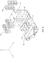
- FIG. 5 is a schematic assembly diagram of the main magnetic module 103, the lateral magnetic module 153, and the base 130.
- the accommodating cavities 110 on the main base 101 are arranged as through-holes and are symmetrically distributed into two rows, and the accommodating cavities 160 on the lateral base 151 are arranged as through-holes and are symmetrically distributed into two rows.
- each lateral magnetic module 153 may move left and right in the corresponding accommodating cavity 160 along an X-axis direction, so as to adjust a distance between each lateral magnetic module 153 and the side face 14 of the wheel 10 shown in FIG. 1 , so that wheels of different side faces and outer profiles may be supported. Further, a magnetic force between each lateral magnetic module 153 and the wheel 10 may be adjusted.
- the main magnetic module 103 and the lateral magnetic module 153 are similar in structure and function. Therefore, with reference to a cross-sectional diagram of the main magnetic module 103 shown in FIG. 6 , an example of a relation between the main magnetic module 103 and the main base 101 is described. As shown in FIG. 6 , the main magnetic module 103 includes at least one magnetic element 201, at least one first fastening element 204, and at least one second fastening element 208.
- the magnetic element 201 may include a magnet or another magnetic force generating element.
- a magnetic force provided for the inspection device 20 to contact the tread 13 and the side face 14 may be regulated by adjusting a quantity, thickness, and material of the magnetic element 201.
- the magnetic element 201 is fixed on the first fastening element 204 by using a screw 202.
- An inner wall of the accommodating cavity 110 is arranged with an internal thread 211 partially or entirely.
- the main magnetic module 103 may extend onto the accommodating cavity 110 from a lower part of the accommodating cavity 110 by fitting an external thread 205 of the first fastening element 204 with the internal thread 211 of the accommodating cavity 110.
- the main magnetic module 103 may extend into the accommodating cavity 110 from an upper part of the accommodating cavity 110.
- the second fastening element 208 may be fixed on a bottom of the first fastening element 204 by fitting an external thread 207 of the second fastening element 208 with the internal thread 211 of the accommodating cavity 110.
- An objective of locking the main magnetic module 103 may be achieved by fitting of first fastening element 204 and the second fastening element 208.
- a hexagonal inner cavity 206 may be arranged inside the first fastening element 204, and a hexagonal inner cavity 209 may be arranged inside the second fastening element 208.
- Art external tool may extend into the hexagonal inner cavity 206 or the hexagonal inner cavity 209 to regulate up-down positions of the first fastening element 204 and the second fastening element 208 in the accommodating cavity 110, so as to adjust a length that the main magnetic module 103 protrudes the accommodating cavity 110, thereby supporting wheels of different outer profiles.
- a length that the lateral magnetic module 153 protrudes the accommodating cavity 160 may also be regulated.
- the rolling module 105 includes a roller body 205, a shaft 254, and two bearings 250 and 252.
- the roller body 205 is fixed on the shaft 254 by using at least one fixed pin 256, and the two bearings 250 and 252 are separately accommodated in the two accommodating cavities 114 and 116, to support the shaft 254 where the roller body 205 is fixed.
- the rolling module 105 may be rotated around the shaft 254 in an axial direction, but cannot be moved along the axial direction.
- one accommodating cavity 116 is further used to accommodate the encoder 106.
- FIG. 8 is a schematic cross-sectional diagram of a inspection device along the A-A line shown in FIG. 2 .
- a fixed pin 258 shown in FIG. 7 is inserted into a fixing hole 257 arranged on the roller body 205, where the fixing hole 257 is perpendicular to the shaft 254, so that the roller body 205 may be rotated to drive rotation of the shaft 254.
- the bearings 250 and 252 pass through the shaft 254 and are sleeved on both sides of the roller body 205.
- the bearing 250 includes a bearing shoulder 251, and when the bearing 250 extends into the accommodating cavity 114, the bearing shoulder 251 may be stuck in an opening of the accommodating cavity 114 and have a position-limiting function in the axial direction.
- the bearing 252 includes a bearing shoulder 253, and when the bearing 252 extends into the accommodating cavity 116, the bearing shoulder 253 may be stuck in one side of an opening of the accommodating cavity 116 and have a position-limiting function in the axial direction.
- An end cap 118 is fixed on a cavity wall at the other side of the opening of the accommodating cavity 116 by using a retaining screw 120, to play a role of sealing the accommodating cavity 116.
- the wheel 10 may drive the inspection device 20 to move from a first position to a second position.
- the rolling module 105 and the wheel 10 roll, so that the rolling module 105 moves the inspection device 20 from the second position to the first position along the tread 13 of the wheel 10.
- the first position is the lowest point of the wheel, and the second position is higher than the first position.
- a magnetic force between the wheel 10 and the inspection device 20 is large enough to overcome weight force of the inspection device 20, to enable the inspection device to keep in the first position or to have small displacement around the first position.
- the encoder 106 includes a stator 104 and a rotor 108, where an inner cavity of the rotor 108 is used to sleeve on the shaft 254, and an outer wall of the rotor 108 extends into the fixing sleeve 258.
- the stator 107 includes a stator shoulder 111. When the encoder 106 extends into the fixing sleeve 258, the stator shoulder 111 may be stuck in the other side of the opening of the accommodating cavity 116, and be fixed on the cavity wall of the accommodating cavity 116 by using the screw 120.
- the roller body 205 of the rolling module 105 closely contacts the tread 13 of the wheel 10, and when the wheel 10 is rotated clockwise, the roller body 205 is rotated anticlockwise under an action of a frictional force.
- the roller body 205 is fixed with the shaft 254, the roller body 205 is rotated to drive rotation of the shaft 254, and further drive rotation of the rotor 108 of the encoder.
- the encoder 106 may transmit a pulse signal sent by the encoder 106 back to an external processor, so as to determine a position of the defect in the wheel 10.
- a position where the wheel 10 contacts the inspection device 20 in a static state, such as the lowest point of the wheel 10, is an initial position.
- N 2 ⁇ is the fixed number of pulses, such as 4,096 pulses, sent by the encoder 1 06 after rotating through a cycle
- N actual is the actual number of pulses detected by the external processor when the defect is detected.
- the circumference distance L wheel that the wheel 10 is rotated through relative to the initial position along the tread 13 may be calculated according to Formulas (1) and (2). Therefore, the external processor may determine the position of defect on the tread 13 or the side face 14 of the wheel 10.
- the sphere support 287 includes a hollow hemispherical cavity 286, a ball layer composed of the plurality of balls 285 is fully arranged on a surface of the hollow hemispherical cavity 286, and the spheres 289 are placed inside the ball layer.
- the inspection device 20 may make a pure rolling motion relative to the wheel 10, so as to reduce a frictional force generated when the inspection device 20 moves relative to the wheel 10.
- the rotatable member 155 may be inserted into a locating hole 265, which is perpendicular to the accommodating cavity 164, by using a locating pin 264 shown in FIG. 7 , to be fixed in the accommodating cavity 164 of the lateral base 151.
- the lateral base 151 when the lateral base 151 is used as a baffle to have a position-limiting function in the axial direction for the wheel 10 shown in FIG. 1 and is not used to detect a defect, the lateral base 151 may be uniformly disposed with a plurality of accommodating cavities 164 for accommodating the rotatable members 155.
- the rotatable member 155 When the wheel 10 is rotated, and when the inspection device 20 moves relative to the wheel 10 under an action of gravity, the rotatable member 155 may make a rolling motion to reduce a frictional force between the lateral base 151 and the side face 14 of the wheel 10.
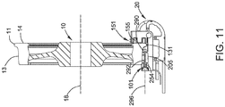
- FIG. 11 is a schematic cross-sectional diagram of the inspection device 20 shown in FIG. 1 and the wheel along a rolling module and a rotatable member.
- an axial line 296 of the shaft 254 is in parallel with an axial line 18 of the wheel 10
- an outline 292 (which is shown more clearly in FIG. 8 and FIG. 9 ) of the roller body 205 matches an outline 290 of the tread of the wheel.
- the roller body 205 with a different outline 292 may be produced according to the outline 290 of a tread of a wheel of a different model. As shown in FIG.
- the rolling module 105 when the two rolling modules 105 are symmetrically installed on both sides of the main base 101, the rolling module 105 may have a radial direction orientation function for the wheel 10. Meanwhile, a distance between the main magnetic module 103 and the tread of the wheel may be adjusted to enable the main magnetic module 103 to fit a space of the wheel 10. As a result, a magnetic force is large enough to ensure that the inspection device 20 is attached onto the wheel 10, and at the same time, a frictional force between the inspection device 20 and the wheel 10 during a relative motion may be reduced.
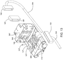
- FIG. 13 is a schematic assembly diagram of a main inspection module, a lateral inspection module, and a base.
- ultrasonic probe arrays are adopted for both the main inspection module 109 and the lateral inspection module 159. Therefore, it is required to fill a gap between the main inspection module 109 and the wheel 10 and a gap between the lateral inspection module 159 and the wheel 10 with a fluid medium.
- the main inspection module 109 is installed in the accommodating cavity 117 shown in FIG. 15 .
- the lateral inspection module 159 is installed in the accommodating cavity 167 shown in FIG. 15 .
- a main sealing ring 107 is adhered to a side surface of the main fluid groove 112, and a side sealing ring 157 is adhered to a side surface of the lateral fluid groove 162.
- a plurality of fixing screws 307 are used to fit threaded holes 306 on an edge of the main fluid groove 112, so as to fix the main sealing ring 107.
- a plurality of fixing screws 357 are used to fit fixing holes 356, so as to fix the side sealing ring 157.
- a probe signal line of the main inspection module 109 is integrated into a main circuit pipeline 308, and a probe signal line of the lateral inspection module 159 is integrated into a side circuit pipeline 358.
- the probe signal lines in the main circuit pipeline 308 and the side circuit pipeline 358 are connected to the external processor, to transmit a detected signal to the external processor to be processed, so as to determine whether the detected wheel has a defect and a depth and a shape of the existed defect.
- the ultrasonic signal when the main inspection module 109 sends an ultrasonic signal, the ultrasonic signal may be broadcast in the fluid medium of the main fluid groove 112 and be transmitted to the tread 13 the wheel rim 15 of the wheel 10.
- the ultrasonic wave When being broadcast to an interface of the defect in the tread 13 or the wheel rim 15, the ultrasonic wave may be entirely or partially reflected, the reflected ultrasonic wave is received by the main inspection module 109, the ultrasonic signal that is reflected back may be transmitted to the external processor via a signal line, and the external processor determines a depth and a shape of the defect of the wheel 10 according to change features of a waveform.
- the external processor may determine a depth, a position, and a shape of the defect of the wheel 10.
- a first end of the handle bar 170 may be permanently connected to the lateral base 151 by using a fixing screw 271.
- a middle part of the handle bar 170 may be permanently connected to the main base 101 by using a fixing screw 273.
- a second end of the handle bar 170 may be permanently connected to the main base 101 by using a fixing screw 275.
- a groove 277 is arranged at the second end of the handle bar 170, and when the handle bar 170 is permanently connected to the main base 101 and the lateral base 151, a space limited by a bottom of the main base 101 and the groove 277 may be used to accommodate and limit a position of the main circuit pipeline 308.
- a groove 279 extending from the first end to the second end is arranged at a lower part of the handle bar 170.
- the handle bar 170 When the handle bar 170 is permanently connected to the main base 101 and the lateral base 151, and after the side circuit pipeline 358 is placed in the groove 279, the first end, the middle end, and the second end of the handle bar 170 are separately fastened with one fastening element 261, and each fastening element 261 is fixed to a corresponding position by using two fixing screws 262, so as to limit a position of the side circuit pipeline 358.
- a channel for injecting fluid is further arranged inside the handle bar 170, and the valve 173 is fixed at an entry 278 of the channel.
- a schematic diagram of the channel for injecting fluid is shown in FIG. 15 .
- a sealing ring 276 is arranged at a joint between the middle part of the handle bar 170 and the main base 101, to seal the channel where fluid enters the main base 101 from the handle bar 170, so as to prevent fluid leakage.
- FIG. 15 is a schematic cross-sectional diagram of the inspection device shown in FIG. 2 along a C-C line.
- the entry 278 of the channel for injecting fluid is connected to the valve 173.
- the channel for injecting fluid includes a channel 280 from the channel entry 278 to the middle part of the handle bar 170 along the handle bar 274, a channel 281 in the middle part of the handle bar 170 and channels 282 and 283, which are in the main base 101 and separately lead to the main fluid groove 112 and the lateral fluid groove 162.
- the valve 173 shown in FIG. 14 is in an open state, fluid may be continuously injected into the main fluid groove 112 and the lateral fluid groove 162 through the foregoing channels 280, 281, 282, and 283.
- a flow rate of the injected fluid is greater than a flow rate that the fluid overflows the main fluid groove 112 and the lateral fluid groove 162.
- channels 284, 285, and 286 are arranged on the main base 101, to guide fluid in the main fluid groove 112 to flow out from a lower outlet 288 of the main base 101 along the channels 284, 285, 286.
- the overflowing fluid may flow out of the main fluid groove 112 and the lateral fluid groove 162 along any path.
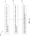
- FIG. 16 is a flowchart of a wheel defect inspection method 1000 according to an implementation manner.
- a sequence of the flowchart shown in FIG. 16 and division of steps in the flowchart are not limited to the shown embodiment.
- the steps in the flowchart may be executed according to a different sequence.
- An action in one step may be combined with another one or more steps, or may be divided into a plurality of steps.
- step 1001 attach a main base of an inspection device onto a tread of the wheel by using at least one main magnetic module.
- step 1003 attach a lateral base of the inspection device onto a side face of the wheel by using at least one lateral magnetic module.
- step 1005 detect at least one type of defect of the wheel by using at least one of the main inspection module and the lateral inspection module.
- the wheel defect inspection method further includes: moving the inspection device from a second position to a first position along the tread of the wheel by rotating at least one rolling module, where the first position is on the bottom of the lowest point of the wheel, and the second position is higher than the lowest point of the wheel.
- a magnetic force between the wheel and the inspection device is large enough to overcome weight force of the inspection device, so as to keep the inspection device in the first position.
- the wheel defect inspection method further includes: injecting fluid into a gap between the tread and a main ultrasonic probe and into a gap between the side face and a lateral ultrasonic probe through a channel, where a flow rate that the fluid flows into the channel is greater than a flow rate that the fluid flows out of the gap.
- the wheel defect inspection method further includes: adjusting a distance between the tread of the wheel and the at least one main magnetic module by rotating at least one first fastening element and second fastening element, to enable the inspection device to support wheels of different outer profiles.
Landscapes
- Physics & Mathematics (AREA)
- General Physics & Mathematics (AREA)
- Biochemistry (AREA)
- Health & Medical Sciences (AREA)
- Life Sciences & Earth Sciences (AREA)
- Chemical & Material Sciences (AREA)
- Analytical Chemistry (AREA)
- General Health & Medical Sciences (AREA)
- Immunology (AREA)
- Pathology (AREA)
- Mechanical Engineering (AREA)
- Engineering & Computer Science (AREA)
- Acoustics & Sound (AREA)
- Investigating Or Analyzing Materials By The Use Of Ultrasonic Waves (AREA)
Description
- The present invention relates to a metal object defect inspection device, and in particular, to a wheel defect inspection device.
- Railway transportation plays a big part in urban transportation. In order to ensure safe running of the railway transportation, a higher requirement is put forward for quality of wheels. In order to prevent a defective wheel from causing an accident during running, and ensure driving safety of a train, it is required to perform defect detection for a tread, a wheel rim, a spoke, and other parts of the wheel. Meanwhile, it is hoped to perform on-line detection (defect detection) without disassembling a wheel set.
DE 20 2006 019808 U1 discloses a device for measuring the properties of rail vehicle wheels comprising electronic sensors for determining wheel profile parameters, tire width and profile contour Further inspection devices and methods of the prior art are disclosed inDE19925394 ,DE10257709C1 andDE10336042A1 . None of these documents disclose a main and a lateral base forming an L-shaped base in combination with a rolling module mounted on the main base for reducing a friction force. - Major causes of a wheel defect include: during smelting and processing of steel used for the wheel, some defects such as gas holes, blisters, inclusions, and scratches are often generated on a surface of the wheel or inside the wheel. Because of existence of these defects, stress concentration may be caused during running of the wheel. In an area of stress concentration, a bearing capacity of metal is small, cracks are prone to extend; under a situation of continuous bearing, the cracks continuously expands, and exfoliation and chipping are generated on the surface of the wheel. In severe cases, risks of wheel "collapsing" or axle breakage may be caused.
- Currently, an effective method is an ultrasonic defect inspection method, such as a piezoelectric ultrasonic defect inspection method. A principle thereof is that: if a wheel has a defect such as a gas hole, a crack, and layering (there is air in the defect), when being broadcast to an interface of the defect, an ultrasonic wave may be entirely or partially reflected, the reflected ultrasonic wave is received by a probe, and a depth, a position, and a shape of the defect of a workpiece may be determined according to change features of a waveform.
- However, when the ultrasonic defect detection is used, it is required to ensure that an air gap between an ultrasonic probe and the detected wheel is filled with fluid, such as water. Therefore, the wheel is usually separated from a locomotive, and then is placed in water, and the ultrasonic probe is placed in the water to perform detection. It is very difficult to have an overall check on the wheel without separating the wheel from the locomotive.
- Therefore, it is necessary to provide an improved system and method to solve the foregoing technical problem.
- The present invention is defined in the accompanying claims.
- In view of the technical problem mentioned above, an aspect of the present invention provides a inspection device for detecting a defect of a metal object, where the inspection device includes a main base, at least one main magnetic module, and a main inspection module. The at least one main magnetic module is installed on the main base, for attaching the main base onto the metal object under an action of a magnetic force. The main inspection module is installed on the main base, to detect at least one type of defect of the metal object.
- In the inspection device described above, the inspection device includes at least one rolling module, the at least one rolling module is installed on the main base, and when there is a relative motion between the main base and the metal object, the at least one rolling module is configured to reduce a frictional force between the main base and the metal object.
- In the inspection device described above, the inspection device includes a lateral base, and the main base and the lateral base are connected together, to form a substantially L-shaped base.
- In the inspection device described above, the inspection device includes at least one rotatable member, the at least one rotatable member is installed on the lateral base, and each rotatable member contacts a surface of the metal object, and rotates along the surface, to enable the lateral base to move relative to the surface.
- In the inspection device described above, the inspection device includes at least one lateral magnetic module, and the at least one lateral magnetic module is installed on the lateral base, for attaching the lateral base onto the metal object under an action of a magnetic force.
- In the inspection device described above, each main magnetic module or each lateral magnetic module includes at least one magnetic element, at least one first fastening element, and at least one second fastening element. The at least one magnetic element is fixed on the at least one first fastening element. Each main magnetic module or each lateral magnetic module is fixed in a corresponding aperture on the main base by using the at least one first fastening element and the at least one second fastening element.
- In the inspection device described above, the at least one first fastening element and the at least one second fastening element are regulated to adjust a length that the main magnetic module or the lateral magnetic module protrudes the corresponding aperture, so as to support metal objects of different outer profiles.
- In the inspection device described above, the lateral base includes a lateral inspection module installed on the lateral base, and the lateral inspection module is configured to detect at least one type of defect of the metal object.
- In the inspection device described above, the main inspection module includes a main ultrasonic probe, the lateral inspection module includes a lateral ultrasonic probe, the main base includes a main fluid groove, and the lateral base includes a lateral fluid groove, where the main fluid groove is injected with fluid, to make a gap between a first surface of the metal object and the main ultrasonic probe filled with fluid. The lateral fluid groove is injected with fluid, to make a gap between a second surface of the metal object and the lateral ultrasonic probe filled with fluid.
- In the inspection device described above, the inspection device includes a handle bar, the handle bar is fixed on the main base and the lateral base, the handle bar includes a channel connected to the main fluid groove and the lateral fluid groove, and the channel is used to provide a path for injecting fluid to the main fluid groove and the lateral fluid groove.
- In the inspection device described above, the inspection device includes two rolling modules, the two rolling modules are separately installed on two opposite edges of the main base, each rolling module includes a roller body, a shaft, and two bearings, the roller body is fixed on the shaft, and the two bearings are separately accommodated in two bearing holes to support the shaft.
- In the inspection device described above, the inspection device includes an encoder, the encoder is fixed with one of the rolling modules, and when the metal object moves from an initial position to a defect position, a position of the defect on a surface of the metal object is determined according to the number of pulses sent by the encoder and a perimeter of the roller body.
- Another aspect of the present invention provides a wheel defect inspection method, where the method includes at least the following steps: attaching a main base of a inspection device onto a tread of a wheel by using at least one main magnetic module; attaching a lateral base of the inspection device to a side face of the wheel by using at least one lateral magnetic module; and detecting at least one type of defect of the wheel by using at least one of the main inspection module and the lateral inspection module.
- In the defect inspection method described above, the method includes: moving the inspection device from a second position to a first position along the tread of the wheel by rotating at least one rolling module; where a magnetic force between the wheel and the inspection device is large enough to overcome weight force of the inspection device, so as to keep the inspection device in the first position.
- In the defect inspection method described above, the method includes: injecting fluid into a gap between the tread and a main ultrasonic probe and into a gap between the side face and a lateral ultrasonic probe through a channel, where a flow rate that the fluid flows into the channel is greater than a flow rate that the fluid flows out of the gap.
- In the defect inspection method described above, the method includes: adjusting a distance between the tread of the wheel and the at least one main magnetic module by rotating at least one first fastening element and second fastening element, to enable the inspection device to support wheels of different tread profiles.
- Yet another aspect of the present invention provides a inspection device, where the inspection device includes a first base, a second base, at least one first magnetic module, a first inspection module, and at least one second magnetic module. The at least one first magnetic module is installed on the first base, for attaching the first base onto a wheel under an action of a first magnetic force. The first inspection module is installed on the first base, to detect at least one type of defect of the wheel. The at least one second magnetic module is installed on the second base, for attaching the second base onto the wheel under an action of a second magnetic force.
- In the inspection device described above, the inspection device includes a second inspection module installed on the second base, and the second inspection module is configured to detect at least one type of defect of the wheel.
- In the inspection device described above, the inspection device includes at least one rolling module, the at least one rolling module is installed on the first base, and when there is a relative motion between the first base and the wheel, the at least one rolling module is configured to reduce a frictional force between the first base and the wheel.
- When the wheel defect inspection device and defect inspection method provided by the present invention are compared with a conventional apparatus and method, on the one hand, a magnetic force generated by a magnetic module may be used to attach the inspection device onto a wheel that is to be detected, and a rolling module is used to enable the inspection device to keep in the lowest point of the wheel under an action of weight force as the rolling module makes a rolling motion relative to a tread of the wheel, and to automatically implement defect detection for a whole circumference of the wheel. When an ultrasonic probe is used for the inspection module, a fluid channel limited by a handle bar may provide a path for injecting fluid into a fluid tank, so as to provide a transmitted ultrasonic wave with a necessary fluid medium. The inspection device may detect a wheel defect without separating the wheel from a vehicle body, thereby improving portability and operability of defect detection.
- The present invention may be understood in a better way by describing the implementation manners of the present invention with reference to the accompanying drawings. In the accompanying drawings:
-
FIG. 1 is a schematic assembly diagram of a inspection device and a wheel; -
FIG. 2 is a schematic three-dimensional diagram of the inspection device shown inFIG. 1 ; -
FIG. 3 is a schematic explosive diagram of components of the inspection device shown inFIG. 2 ; -
FIG. 4 is a schematic three-dimensional diagram of a base shown inFIG. 2 according to an implementation manner; -
FIG. 5 is a schematic assembly diagram of a main magnetic module, a lateral magnetic module, and a base; -
FIG. 6 is a cross-sectional diagram of a main magnetic module; -
FIG. 7 is a schematic assembly diagram of a rolling module, a rotatable member, and a base; -
FIG. 8 is a schematic cross-sectional diagram of the inspection device shown inFIG. 2 along an A-A line; -
FIG. 9 is a schematic cross-sectional diagram of the inspection device shown inFIG. 2 along a B-B line; -
FIG. 10 is a cross-sectional diagram of the rotatable member shown inFIG. 7 ; -
FIG. 11 is a schematic cross-sectional diagram of the inspection device shown inFIG. 1 and a wheel along a rolling module and a rotatable member; -
FIG. 12 is a schematic cross-sectional diagram of the inspection device shown inFIG. 1 and a wheel along a rolling module and a main magnetic module; -
FIG. 13 is a schematic assembly diagram of a main inspection module, a lateral inspection module, and a base; -
FIG. 14 is a schematic assembly diagram of a handle bar and a base; -
FIG. 15 is a schematic cross-sectional diagram of the inspection device shown inFIG. 2 along a C-C line; and -
FIG. 16 is a flowchart of a wheel defect inspection method according to an implementation manner. - The following will describe specific implementation manners of the present invention. It should be noted that, in the specific description process of these implementation manners, in order to make terse and concise descriptions, it is impossible to describe in the specification all features of an actual implementation manner in detail. It should be understood that, in an actual implementation process of any one implementation manner, as in a process of any one project or design project, in order to achieve the developers' specific goals, and in order to meet system-related or business-related limitations, various specific decisions may usually be made, and the decisions may change from one embodiment to another embodiment. In addition, it can also be understood that, although efforts made in the development process may be complicated and lengthy, for a person of ordinary skill in the art related to the content disclosed in the present invention, some changes, such as in design, manufacturing, or production, made based on the technical content disclosed in the appended claims are common technical means.
- Unless otherwise defined, the technical terms or scientific terms used in the claims and specification should be the ordinary meaning understood by a person of ordinary skill in the technical field of the present invention. "First", "second" and similar words used in the patent application specification and claims of the present invention do not denote any order, quantity, or importance, but are just used to distinguish different components. "A" or "an" and other similar words do not denote quantity limitations, but denote that at least one exists. "Comprises" or "comprising" and other similar words imply that an element or object appearing before the "comprises" or "comprising" covers enumerated elements or objects and equivalents elements thereof appearing after the "comprises" or "comprising", without excluding other elements or objects. "Disposed", "connected", or "connecting" and other similar words are neither limited to physical or mechanical connections, nor limited to direct or indirect connections.
- "May", "can", "possible", and other words used in the present invention indicate a possibility of an event in some environments, and possessing a specific attribute, feature or function; and/or represent, by combining with a qualified verb, one or more capabilities, performance, or possibilities. Correspondingly, the use of "possible" indicates that: a modified term is clearly suitable, matchable, or appropriate for a shown capability, function, or purpose. Further, considering existence of some situations, sometimes, the modified term may not be suitable, matchable, or appropriate. For example, in some cases, a result or performance may come out as expected, while in other cases, the result or performance may not come out. This difference is embodied by the word that expresses "possibility".
- Referring to
FIG. 1, FIG. 1 shows a schematic assembly diagram of ainspection device 20 and awheel 10 disclosed by the present invention. As shown inFIG. 1 , in a radial direction from a central spindle (along a position where anaxial line 18 is located) of thewheel 10, there are successively, awheel hub 19, aspoke 17 connected to thewheel hub 19, and awheel rim 15 connected to thespoke 17. A surface of thewheel rim 15 includes atread 13, awheel flange 11, and aside face 14. An interior state of thewheel 10, such as a state of thewheel rim 15, thespoke 17, and thewheel hub 19, or a surface state, such as a state of thetread 13 and theside face 14, is directly related to traffic safety. Therefore, in the implementation manner, theinspection device 20 is configured to detect an interior and/or a surface defect of thewheel 10. The defect may include a shortcoming or fault in any form, such as an interior crack or a surface crack. More specifically, theinspection device 20 may be used to detect a defect of thetread 13, theside face 14, and the wheel rim 15 of thewheel 10, and determine a depth, a position, and a shape of the defect of thewheel 10. Theinspection device 20 provided by the present invention is not limited to detect the defect of thewheel 10, and may further be configured to detect a defect of another metal object. - When the
inspection device 20 is used to detect the defect inside thewheel 10 and/or on the surface of thewheel 10, in some implementation manners, thewheel 10 may be separated from a vehicle body, to perform detection separately. In other implementation manners, detection may also be performed without separating thewheel 10 from the vehicle body. For example, heavy equipment is used to elevate the vehicle body, and theinspection device 20 may be automatically attached onto a bottom of thewheel 10 under an action of a magnetic force. More specifically, when thewheel 10 is rotated slowly along theaxial line 18 of wheel, in an implementation manner, theinspection device 20 moves relative to thewheel 10 under the combined action of gravity and a magnetic force, so that theinspection device 20 automatically keeps in a bottom of the lowest point of thewheel 10 relative to thewheel 10. In other implementation manners, an additional auxiliary apparatus, such as a support, may be configured to support theinspection device 20, to make theinspection device 20 stable and static in any point where theinspection device 20 closely contacts thewheel 10, such as the highest point of thewheel 10. As thewheel 10 is slowly rotated, both thetread 13 and theside face 14 of the whole wheel have an opportunity to contact theinspection device 20, and theinspection device 20 may detect an interior and/or a surface defect near a position where theinspection device 20 contacts thewheel 10. Therefore, theinspection device 20 may detect a circumference of the whole wheel. - Referring to
FIG. 2, FIG. 2 is a schematic three-dimensional diagram of theinspection device 20 shown inFIG. 1 . Theinspection device 20 includes afirst detection component 22 along an XY plane. When performing detection for thewheel 10 shown inFIG. 1 , thefirst detection component 22 may be attached onto a surface of thetread 13 of thewheel 10 under an action of a magnetic force, so as to detect a surface detect of thetread 13 and an interior defect of thewheel hub 15. - The
inspection device 20 further includes asecond detection component 24 along an YZ plane. When performing detection for thewheel 10 shown inFIG. 1 , thesecond detection component 24 may be attached onto a surface of theside face 14 of thewheel 10 under an action of a magnetic force, so as to detect a surface defect of theside face 14 and an interior defect of thewheel hub 15. - To facilitate holding of the
first detection component 22 and thesecond detection component 24, the inspection device 26 further includes ahandle bar 170 connected outside thefirst detection component 22 and thesecond detection component 24. - In some implementation manners, the
inspection device 20 may include thefirst detection component 22 only or include thesecond detection component 24 only. With the help of an external support, thefirst detection component 22 or thesecond detection component 24 may be successively attached onto thetread 13 and theside face 14 of thewheel 10, so as to perform comprehensive detection for the circumference of thewheel 10. In some implementation manners, theinspection device 20 includes thefirst detection component 22 and thesecond detection component 24, the first andsecond detection components first detection component 22 and thesecond detection component 24 are connected together, to combine into a substantially L-shaped component with an included angle of approximately 90°. In other implementation manners, theinspection device 20 includes thefirst detection component 22 and thesecond detection component 24, and the first andsecond detection components tread 13 and theside face 14 of thewheel 10, so that theinspection device 20 and the wheel 1 0 are clamped. - Referring to
FIG. 3, FIG. 3 is a schematic explosive diagram of theinspection device 20 shown inFIG. 2 . Theinspection device 20 includes a substantially L-shapedbase 130, and the substantially L-shapedbase 130 includes a plurality of accommodating cavities for accommodating at least one mainmagnetic module 103, at least one lateralmagnetic module 153, amain inspection module 109, alateral inspection module 159, at least onerolling module 105, and at least onerotatable member 155. - In some implementation manners, the
main inspection module 109 and theside inspection module 159 are configured to detect at least one type of defect of at least one of thetread 13, theside face 14, and the wheel rim 15 of thewheel 10 shown inFIG. 1 . In an implementation manner, when ultrasonic probe arrays are used for themain inspection module 109 and thelateral inspection module 159, the substantially L-shapedbase 130 further includes a mainfluid groove 112 and a lateralfluid groove 162. The mainfluid groove 112 and the lateralfluid groove 162 are filled with a fluid medium. Ultrasonic waves transmitted by themain inspection module 109 and thelateral inspection module 159 are transmitted to the tread 1 3 and theside face 14 of thewheel 10 via the fluid medium. In an implementation manner, as shown inFIG. 15 , themain inspection module 109 is placed in anaccommodating cavity 117 in a lower part of the mainfluid groove 112. Thelateral inspection module 159 is placed in an accommodating cavity 167 on a right side of the lateralfluid groove 162. - The rolling
module 105 closely contacts thetread 13 of thewheel 10 shown inFIG. 1 , and therotatable member 155 closely contacts theside face 14 of thewheel 10. When thewheel 10 is rotated along a direction, such as clockwise, theinspection device 20 is rotated anticlockwise under an action of its own weight force and a magnetic force of the mainmagnetic module 103 and the lateralmagnetic module 153 as rolling friction occurs in a part where the rollingmodule 105 contacts thetread 13 of thewheel 10, so that theinspection device 20 may automatically keep in the bottom of the lowest point of thewheel 10. When theinspection device 20 is displaced relative to thewheel 10, a part where therotatable member 155 contacts theside face 14 of thewheel 10 rolls, to reduce a frictional force between theinspection device 20 and theside face 14 of the wheel, sp as to facilitate theinspection device 20 to quickly return to and keep in the bottom of the lowest point of thewheel 10. - After the at least one main
magnetic module 103, the at least one lateralmagnetic module 153, themain inspection module 109, thelateral inspection module 159, the at least onerolling module 105, and the at least onerotatable member 155 are installed in the accommodating cavities of the substantially L-shapedbase 130, to facilitate holding of the substantially L-shaped base 1 30, theinspection device 20 further includes ahandle bar 170 connected outside the substantially L-shapedbase 130. When it is required to inject fluid into the mainfluid groove 112 and the lateralfluid groove 162 of the substantially L-shapedbase 130, thehandle bar 170 may be connected to avalve 173. When thevalve 173 is opened, fluid may be injected into the mainfluid groove 112 and the lateralfluid groove 162 through thevalve 173 via a fluid channel limited inside thehandle bar 170. - The
inspection device 20 further includes anencoder 106, and theencoder 106 is fixed with one of the rollingmodules 105. Theencoder 106, themain inspection module 109, and thelateral inspection module 159 may communicate with an external processor (not shown), to detect defect and determine a depth, a shape, and a position of the defect of thewheel 10. - The following describes components of the
inspection device 20 in detail with reference toFIG. 4 to FIG. 14 .FIG. 5 to FIG. 14 are an installation sequence that each component is installed on thebase 130, and in other implementation manners, an installation sequence is not limited to the sequence described in the present invention. For example, the installation sequence of the components may be determined according to principles of facilitation and rapidness. - Referring to
FIG. 4, FIG. 4 is a schematic three-dimensional diagram of the base 130 shown inFIG. 3 according to an implementation manner. In the implementation manner, thebase 130 includes amain base 101 and alateral base 151. Themain base 101 includes a plurality of accommodatingcavities 110 for accommodating the mainmagnetic modules 103, an accommodating cavity 117 (seeFIG. 15 ) for accommodating themain inspection module 109, andaccommodating cavities modules 105. When an ultrasonic probe array is used for themain inspection module 109 shown inFIG. 3 , themain base 101 further includes a mainfluid groove 112, and the mainfluid groove 112 is filled with a fluid medium. An ultrasonic wave transmitted by themain inspection module 109 is transmitted to thetread 13 of thewheel 10 via the fluid medium. - In some implementation manners, the plurality of accommodating
cavities 110 are through-holes and are symmetrically distributed into two rows. Theaccommodating cavity 117 and the mainfluid groove 112 are disposed in a part between the two rows of accommodatingcavities 110. More specifically, as shown inFIG. 15 , theaccommodating cavity 117 is disposed in a lower part of the part between the two rows of accommodatingcavities 110, and the mainfluid groove 112 is disposed in an upper part of the part between the two rows of accommodatingcavities 110. When theaccommodating cavity 117 is used to accommodate an ultrasonic probe array to detect the defect of thewheel 10, themain inspection module 109 transmits an ultrasonic wave along a Z-axis direction, so as to transmit the ultrasonic wave from thetread 13 of the wheel 1 0 to the wheel rim 15 of thewheel 10 via the mainfluid groove 112. In this case, it is necessary to continuously inject fluid such as water to the mainfluid groove 112, to use the fluid as a medium required for transmission of the ultrasonic wave. In the implementation manner, the mainfluid groove 112 and theaccommodating cavity 117 are interconnected. In other implementation manners, a complete through-hole is disposed in the part between the two rows of accommodatingcavities 110. When themain inspection module 109 is an ultrasonic probe that needs a fluid medium, a lower part of the through-hole is used to accommodate the ultrasonic probe, and an upper part of the through-hole is used to inject fluid. When themain inspection module 109 is a probe that does not need a fluid medium, such as an electromagnetic ultrasonic probe, the through-hole is used to accommodate the electromagneticultrasonic probe 109. - The
lateral base 151 includes a plurality of accommodatingcavities 160 for accommodating the lateralmagnetic modules 153, an accommodating cavity 167 (seeFIG. 15 ) for accommodating thelateral inspection module 159, and anaccommodating cavity 164 for accommodating therotatable member 155. When an ultrasonic probe array is used for thelateral inspection module 159 shown inFIG. 3 , thelateral base 151 further includes a lateralfluid groove 162, and the lateralfluid groove 162 is filled with a fluid medium. An ultrasonic wave transmitted by thelateral inspection module 159 is transmitted to theside face 14 of thewheel 10 via the fluid medium. - In some implementation manners, the plurality of accommodating
cavities 160 are through-holes and are symmetrically distributed into two rows. The accommodating cavity 167 and the mainfluid groove 162 are disposed in a part between the two rows of accommodatingcavities 160. More specifically, as shown inFIG. 15 , the accommodating cavity 167 is disposed in a right part of the part between the two rows of accommodatingcavities 160, and the lateralfluid groove 162 is disposed in a left part of the part between the two rows of accommodatingcavities 160. When the accommodating cavity 167 is used to accommodate an ultrasonic probe array to detect the defect of thewheel 10, thelateral inspection module 159 transmits an ultrasonic wave along an X-axis direction, so as to transmit the ultrasonic wave from theside face 14 of thewheel 10 to the wheel rim 15 of thewheel 10 via the lateralfluid groove 162. In this case, it is necessary to continuously inject fluid such as water to the lateralfluid groove 162, to use the fluid as a medium required for transmission of the ultrasonic wave. In the implementation manner, the lateralfluid groove 162 and the accommodating cavity 167 are interconnected. In other implementation manners, a complete through-hole is disposed in the part between the two rows of accommodating cavities 1 60. When thelateral inspection module 159 is an ultrasonic probe that needs a fluid medium, a right part of the through-hole is used to accommodate the ultrasonic probe, and a left part of the through-hole is used to inject fluid. When thelateral inspection module 159 is a probe that does not need a fluid medium, such as an electromagnetic ultrasonic probe, the through-hole is used to accommodate the electromagneticultrasonic probe 159. - In some implementation manners, the
lateral base 151 is merely used as a baffle, to have an axial position-limiting function for thewheel 10 shown inFIG. 1 . That is, when thewheel 10 shown inFIG. 1 is rotated along theaxial line 18, an area limited by thelateral base 151 and themain base 101 matches an outline of thewheel 10, so as to achieve an objective of clamping thewheel 10. In this case, no components are installed on thelateral base 151. That is, no inspection modules for detecting the defect of thewheel 10 are installed on thelateral base 151, and thelateral base 151 does not detect the defect of thewheel 10. - Referring to
FIG. 5, FIG. 5 is a schematic assembly diagram of the mainmagnetic module 103, the lateralmagnetic module 153, and thebase 130. Theaccommodating cavities 110 on themain base 101 are arranged as through-holes and are symmetrically distributed into two rows, and theaccommodating cavities 160 on thelateral base 151 are arranged as through-holes and are symmetrically distributed into two rows. - A model and a degree of wear of the wheel may affect an outline and a shape of the wheel. In order to ensure that the
inspection device 20 may perform detection for wheels of various models and different degrees of wear, each mainmagnetic module 103 may move up and down in the correspondingaccommodating cavity 110 along a Z-axis direction, so as to adjust a distance between each mainmagnetic module 103 and thetread 13 of thewheel 10 shown inFIG. 1 , so that wheels of different treads and outer profiles may be supported. Further, a magnetic force between each mainmagnetic module 103 and thewheel 10 may be adjusted. Similarly, each lateralmagnetic module 153 may move left and right in the correspondingaccommodating cavity 160 along an X-axis direction, so as to adjust a distance between each lateralmagnetic module 153 and theside face 14 of thewheel 10 shown inFIG. 1 , so that wheels of different side faces and outer profiles may be supported. Further, a magnetic force between each lateralmagnetic module 153 and thewheel 10 may be adjusted. - The main
magnetic module 103 and the lateralmagnetic module 153 are similar in structure and function. Therefore, with reference to a cross-sectional diagram of the mainmagnetic module 103 shown inFIG. 6 , an example of a relation between the mainmagnetic module 103 and themain base 101 is described. As shown inFIG. 6 , the mainmagnetic module 103 includes at least onemagnetic element 201, at least onefirst fastening element 204, and at least onesecond fastening element 208. - The
magnetic element 201 may include a magnet or another magnetic force generating element. A magnetic force provided for theinspection device 20 to contact thetread 13 and theside face 14 may be regulated by adjusting a quantity, thickness, and material of themagnetic element 201. In the implementation manner, themagnetic element 201 is fixed on thefirst fastening element 204 by using ascrew 202. An inner wall of theaccommodating cavity 110 is arranged with an internal thread 211 partially or entirely. In an implementation manner, the mainmagnetic module 103 may extend onto theaccommodating cavity 110 from a lower part of theaccommodating cavity 110 by fitting anexternal thread 205 of thefirst fastening element 204 with the internal thread 211 of theaccommodating cavity 110. In other implementation manners, the mainmagnetic module 103 may extend into theaccommodating cavity 110 from an upper part of theaccommodating cavity 110. - When the threads of the
first fastening element 204 and theaccommodating cavity 110 are connected and fixed, thesecond fastening element 208 may be fixed on a bottom of thefirst fastening element 204 by fitting anexternal thread 207 of thesecond fastening element 208 with the internal thread 211 of theaccommodating cavity 110. An objective of locking the mainmagnetic module 103 may be achieved by fitting offirst fastening element 204 and thesecond fastening element 208. - A hexagonal
inner cavity 206 may be arranged inside thefirst fastening element 204, and a hexagonalinner cavity 209 may be arranged inside thesecond fastening element 208. Art external tool may extend into the hexagonalinner cavity 206 or the hexagonalinner cavity 209 to regulate up-down positions of thefirst fastening element 204 and thesecond fastening element 208 in theaccommodating cavity 110, so as to adjust a length that the mainmagnetic module 103 protrudes theaccommodating cavity 110, thereby supporting wheels of different outer profiles. Similarly, a length that the lateralmagnetic module 153 protrudes theaccommodating cavity 160 may also be regulated. - Referring to
FIG. 7, FIG. 7 is a schematic assembly diagram of the rollingmodule 105, therotatable member 155, and thebase 130. On the one hand, to implement that theinspection device 20 automatically keeps stable in a position of the lowest point of thewheel 10 under an action of gravity, and on the other hand, to reduce rigid friction between theinspection device 20 and thewheel 10, at least onerolling module 105 is arranged on themain base 101, and at least onerotatable member 155 is arranged on thelateral base 151. - More specifically, in the implementation manner, two rolling
modules 105 are separately installed on two edges, which are parallel to the X-axis, of themain base 101. As shown inFIG. 7 , the rollingmodule 105 includes aroller body 205, ashaft 254, and twobearings roller body 205 is fixed on theshaft 254 by using at least one fixedpin 256, and the twobearings accommodating cavities shaft 254 where theroller body 205 is fixed. The rollingmodule 105 may be rotated around theshaft 254 in an axial direction, but cannot be moved along the axial direction. In some implementation manners, oneaccommodating cavity 116 is further used to accommodate theencoder 106. - The rolling
module 105 is described in detail with reference toFIG. 8 , which is a schematic cross-sectional diagram of a inspection device along the A-A line shown inFIG. 2 . After theshaft 254 passes through theroller body 205, a fixedpin 258 shown inFIG. 7 is inserted into a fixinghole 257 arranged on theroller body 205, where the fixinghole 257 is perpendicular to theshaft 254, so that theroller body 205 may be rotated to drive rotation of theshaft 254. Thebearings shaft 254 and are sleeved on both sides of theroller body 205. Thebearing 250 includes abearing shoulder 251, and when thebearing 250 extends into theaccommodating cavity 114, the bearingshoulder 251 may be stuck in an opening of theaccommodating cavity 114 and have a position-limiting function in the axial direction. Similarly, thebearing 252 includes abearing shoulder 253, and when thebearing 252 extends into theaccommodating cavity 116, the bearingshoulder 253 may be stuck in one side of an opening of theaccommodating cavity 116 and have a position-limiting function in the axial direction. Anend cap 118 is fixed on a cavity wall at the other side of the opening of theaccommodating cavity 116 by using a retainingscrew 120, to play a role of sealing theaccommodating cavity 116. - Under an action of a magnetic force, when the
wheel 10 is rotated, thewheel 10 may drive theinspection device 20 to move from a first position to a second position. Under an action of gravity, the rollingmodule 105 and thewheel 10 roll, so that the rollingmodule 105 moves theinspection device 20 from the second position to the first position along thetread 13 of thewheel 10. In the implementation manner, the first position is the lowest point of the wheel, and the second position is higher than the first position. A magnetic force between thewheel 10 and theinspection device 20 is large enough to overcome weight force of theinspection device 20, to enable the inspection device to keep in the first position or to have small displacement around the first position. - The
encoder 106 is described in detail with reference toFIG. 9 , which is a schematic cross-sectional diagram of a inspection device along the B-B line shown inFIG. 2 . Compared with the rollingmodule 105 shown inFIG. 8 , theaccommodating cavity 116 is further used to accommodate a fixingsleeve 258 and theencoder 106. The fixingsleeve 258 is fixed inside theaccommodating cavity 116. In theaccommodating cavity 116, an end of the fixingsleeve 258 is pressed against the bearing 252, and the other end of the fixingsleeve 258 is used to accommodate theencoder 106. Theencoder 106 includes astator 104 and arotor 108, where an inner cavity of therotor 108 is used to sleeve on theshaft 254, and an outer wall of therotor 108 extends into the fixingsleeve 258. Thestator 107 includes astator shoulder 111. When theencoder 106 extends into the fixingsleeve 258, thestator shoulder 111 may be stuck in the other side of the opening of theaccommodating cavity 116, and be fixed on the cavity wall of theaccommodating cavity 116 by using thescrew 120. - As shown in
FIG. 12 , theroller body 205 of the rollingmodule 105 closely contacts thetread 13 of thewheel 10, and when thewheel 10 is rotated clockwise, theroller body 205 is rotated anticlockwise under an action of a frictional force. Refer toFIG. 9 again. Since theroller body 205 is fixed with theshaft 254, theroller body 205 is rotated to drive rotation of theshaft 254, and further drive rotation of therotor 108 of the encoder. Theencoder 106 may transmit a pulse signal sent by theencoder 106 back to an external processor, so as to determine a position of the defect in thewheel 10. - More specifically, in some implementation manners, a position where the
wheel 10 contacts theinspection device 20 in a static state, such as the lowest point of thewheel 10, is an initial position. When themain inspection module 109 and/or thelateral inspection module 159 detect(s) a defect, a position where theinspection device 20 contacts thewheel 10 is a defect position, and a circumference distance Lwheel that thewheel 10 is rotated clockwise to the defect position relative to the initial position along thetread 13 may be calculated by the following formula:
- where when the wheel 1 0 is rotated clockwise from the initial position to the defect position along the
axial line 18, Lroller is a circumference distance that theroller body 205 is rotated through, L is a perimeter that theroller body 205 is rotated through a cycle, nroller is a circumference number that theroller body 205 is rotated through, and nencoder is a circumference number that therotor 108 of the encoder is rotated through. Since a relative motion between thetread 13 of thewheel 10 and the rollingmodule 105 is rolling, Lwheel equals Lroller; and since the rollingmodule 105 is rotated to drive rotation of therotor 108 of the encoder, nroller equals nencoder. - It can be known from Formula (1) that, when L is a given value or a numerical value that can be obtained by measurement, it is merely necessary to detect nencoder to obtain Lwheel, so as to determine the position of the defect on the
tread 13 or theside face 14 of thewheel 10 relative to the initial position. nencoder may be calculated by the following formula:
- where N2π is the fixed number of pulses, such as 4,096 pulses, sent by the encoder 1 06 after rotating through a cycle, and Nactual is the actual number of pulses detected by the external processor when the defect is detected. When the defect is detected, the circumference distance Lwheel that the
wheel 10 is rotated through relative to the initial position along thetread 13 may be calculated according to Formulas (1) and (2). Therefore, the external processor may determine the position of defect on thetread 13 or theside face 14 of thewheel 10. - The
rotatable member 155 is described in detail with reference toFIG. 10 , which is a cross-sectional diagram that therotatable member 155 is installed on thelateral base 151. In the implementation manner, therotatable member 155 is a universal rotatable member, and fourrotatable members 155 are uniformly distributed and installed on thelateral base 151. More specifically, therotatable member 155 includes asphere 289, a plurality ofballs 285, and asphere support 287. Thesphere support 287 includes a hollowhemispherical cavity 286, a ball layer composed of the plurality ofballs 285 is fully arranged on a surface of the hollowhemispherical cavity 286, and thespheres 289 are placed inside the ball layer. When thesphere 289 contacts theside face 14 of thewheel 10 and has relative displacement, thesphere 289 may be rotated universally. As a result, theinspection device 20 may make a pure rolling motion relative to thewheel 10, so as to reduce a frictional force generated when theinspection device 20 moves relative to thewheel 10. Therotatable member 155 may be inserted into a locatinghole 265, which is perpendicular to theaccommodating cavity 164, by using alocating pin 264 shown inFIG. 7 , to be fixed in theaccommodating cavity 164 of thelateral base 151. - In some implementation manners, when the
lateral base 151 is used as a baffle to have a position-limiting function in the axial direction for thewheel 10 shown inFIG. 1 and is not used to detect a defect, thelateral base 151 may be uniformly disposed with a plurality of accommodatingcavities 164 for accommodating therotatable members 155. When thewheel 10 is rotated, and when theinspection device 20 moves relative to thewheel 10 under an action of gravity, therotatable member 155 may make a rolling motion to reduce a frictional force between thelateral base 151 and theside face 14 of thewheel 10. - Referring to
FIG. 11, FIG. 11 is a schematic cross-sectional diagram of theinspection device 20 shown inFIG. 1 and the wheel along a rolling module and a rotatable member. As shown inFIG. 11 , when theinspection device 20 is assembled with thewheel 10, anaxial line 296 of theshaft 254 is in parallel with anaxial line 18 of thewheel 10, and an outline 292 (which is shown more clearly inFIG. 8 and FIG. 9 ) of theroller body 205 matches anoutline 290 of the tread of the wheel. When theroller body 205 is being processed, theroller body 205 with adifferent outline 292 may be produced according to theoutline 290 of a tread of a wheel of a different model. As shown inFIG. 12 , when the two rollingmodules 105 are symmetrically installed on both sides of themain base 101, the rollingmodule 105 may have a radial direction orientation function for thewheel 10. Meanwhile, a distance between the mainmagnetic module 103 and the tread of the wheel may be adjusted to enable the mainmagnetic module 103 to fit a space of thewheel 10. As a result, a magnetic force is large enough to ensure that theinspection device 20 is attached onto thewheel 10, and at the same time, a frictional force between theinspection device 20 and thewheel 10 during a relative motion may be reduced. - Refer to
FIG. 11 again. When theinspection device 20 is assembled with thewheel 10, therotatable member 155 closely contacts theside face 14 of thewheel 11, so as to provide an axial direction orientation function for thewheel 10. Meanwhile, a corner where themain base 101 is connected to thelateral base 151 is processed as agroove 131 matching thewheel flange 11 of thewheel 10. When theinspection device 20 is assembled with thewheel 10, thegroove 131 may be used to accommodate thewheel flange 11 of thewheel 10, to further provide an orientation function for thewheel 10. - Referring to
FIG. 13, FIG. 13 is a schematic assembly diagram of a main inspection module, a lateral inspection module, and a base. In the implementation manner, ultrasonic probe arrays are adopted for both themain inspection module 109 and thelateral inspection module 159. Therefore, it is required to fill a gap between themain inspection module 109 and thewheel 10 and a gap between thelateral inspection module 159 and thewheel 10 with a fluid medium. Themain inspection module 109 is installed in theaccommodating cavity 117 shown inFIG. 15 . Thelateral inspection module 159 is installed in the accommodating cavity 167 shown inFIG. 15 . In some implementation manners, amain sealing ring 107 is adhered to a side surface of the mainfluid groove 112, and aside sealing ring 157 is adhered to a side surface of the lateralfluid groove 162. As shown inFIG. 13 , a plurality of fixingscrews 307 are used to fit threadedholes 306 on an edge of the mainfluid groove 112, so as to fix themain sealing ring 107. A plurality of fixingscrews 357 are used to fit fixingholes 356, so as to fix theside sealing ring 157. When theinspection device 20 is attached onto thewheel 10, anupper surface 137 of themain sealing ring 107 closely contacts thetread 13 of thewheel 10, to have a function of sealing fluid inside the mainfluid groove 112, thereby reducing overflowing of the fluid medium in the mainfluid groove 112. Aleft side surface 187 of theside sealing ring 157 closely contacts theside face 14 of thewheel 10, to have a function of sealing fluid inside the lateralfluid groove 162, thereby reducing overflowing of the fluid medium in the lateralfluid groove 162. - A probe signal line of the
main inspection module 109 is integrated into amain circuit pipeline 308, and a probe signal line of thelateral inspection module 159 is integrated into aside circuit pipeline 358. The probe signal lines in themain circuit pipeline 308 and theside circuit pipeline 358 are connected to the external processor, to transmit a detected signal to the external processor to be processed, so as to determine whether the detected wheel has a defect and a depth and a shape of the existed defect. - More specifically, in some implementation manners, when the
main inspection module 109 sends an ultrasonic signal, the ultrasonic signal may be broadcast in the fluid medium of the mainfluid groove 112 and be transmitted to thetread 13 the wheel rim 15 of thewheel 10. When being broadcast to an interface of the defect in thetread 13 or thewheel rim 15, the ultrasonic wave may be entirely or partially reflected, the reflected ultrasonic wave is received by themain inspection module 109, the ultrasonic signal that is reflected back may be transmitted to the external processor via a signal line, and the external processor determines a depth and a shape of the defect of thewheel 10 according to change features of a waveform. - Therefore, according to signals transmitted by the
encoder 106 shown inFIG. 7 , themain inspection module 109 and thelateral inspection module 159 shown inFIG. 13 to the external processor, the external processor may determine a depth, a position, and a shape of the defect of thewheel 10. - Referring to
FIG. 14, FIG. 14 is a schematic assembly diagram of thehandle bar 170 and the base. Refer toFIG. 8 . In order to improve portability of theinspection device 20, thehandle bar 170 is disposed with two handlebars inspection device 20 and thewheel 10 is large, and it is required to remove theinspection device 20, the handle bars 272 and 274 may be held by hands. - A first end of the
handle bar 170 may be permanently connected to thelateral base 151 by using a fixingscrew 271. A middle part of thehandle bar 170 may be permanently connected to themain base 101 by using a fixingscrew 273. A second end of thehandle bar 170 may be permanently connected to themain base 101 by using a fixingscrew 275. Agroove 277 is arranged at the second end of thehandle bar 170, and when thehandle bar 170 is permanently connected to themain base 101 and thelateral base 151, a space limited by a bottom of themain base 101 and thegroove 277 may be used to accommodate and limit a position of themain circuit pipeline 308. Agroove 279 extending from the first end to the second end is arranged at a lower part of thehandle bar 170. When thehandle bar 170 is permanently connected to themain base 101 and thelateral base 151, and after theside circuit pipeline 358 is placed in thegroove 279, the first end, the middle end, and the second end of thehandle bar 170 are separately fastened with onefastening element 261, and eachfastening element 261 is fixed to a corresponding position by using two fixingscrews 262, so as to limit a position of theside circuit pipeline 358. - A channel for injecting fluid is further arranged inside the
handle bar 170, and thevalve 173 is fixed at anentry 278 of the channel. A schematic diagram of the channel for injecting fluid is shown inFIG. 15 . A sealingring 276 is arranged at a joint between the middle part of thehandle bar 170 and themain base 101, to seal the channel where fluid enters themain base 101 from thehandle bar 170, so as to prevent fluid leakage. - Referring to
FIG. 15, FIG. 15 is a schematic cross-sectional diagram of the inspection device shown inFIG. 2 along a C-C line. Theentry 278 of the channel for injecting fluid is connected to thevalve 173. The channel for injecting fluid includes achannel 280 from thechannel entry 278 to the middle part of thehandle bar 170 along thehandle bar 274, achannel 281 in the middle part of thehandle bar 170 andchannels main base 101 and separately lead to the mainfluid groove 112 and the lateralfluid groove 162. When thevalve 173 shown inFIG. 14 is in an open state, fluid may be continuously injected into the mainfluid groove 112 and the lateralfluid groove 162 through the foregoingchannels - In order to ensure that a space between contact faces of the
inspection device 20 and thewheel 10, particularly, spaces between themain inspection module 109 and thelateral inspection device 159 and thewheel 10, is filled with fluid, in some implementation manners, a flow rate of the injected fluid is greater than a flow rate that the fluid overflows the mainfluid groove 112 and the lateralfluid groove 162. In some implementation manners,channels main base 101, to guide fluid in the mainfluid groove 112 to flow out from alower outlet 288 of themain base 101 along thechannels fluid groove 112 and the lateralfluid groove 162 along any path. - Referring to
FIG. 1 6 ,FIG. 16 is a flowchart of a wheeldefect inspection method 1000 according to an implementation manner. A sequence of the flowchart shown inFIG. 16 and division of steps in the flowchart are not limited to the shown embodiment. For example, the steps in the flowchart may be executed according to a different sequence. An action in one step may be combined with another one or more steps, or may be divided into a plurality of steps. - In step 1001: attach a main base of an inspection device onto a tread of the wheel by using at least one main magnetic module. In step 1003: attach a lateral base of the inspection device onto a side face of the wheel by using at least one lateral magnetic module. In step 1005: detect at least one type of defect of the wheel by using at least one of the main inspection module and the lateral inspection module.
- When the inspection device is configured to detect at least one type of defect of the wheel, the wheel defect inspection method further includes: moving the inspection device from a second position to a first position along the tread of the wheel by rotating at least one rolling module, where the first position is on the bottom of the lowest point of the wheel, and the second position is higher than the lowest point of the wheel. A magnetic force between the wheel and the inspection device is large enough to overcome weight force of the inspection device, so as to keep the inspection device in the first position.
- When ultrasonic probes are used as the main inspection module and the lateral inspection device, the wheel defect inspection method further includes: injecting fluid into a gap between the tread and a main ultrasonic probe and into a gap between the side face and a lateral ultrasonic probe through a channel, where a flow rate that the fluid flows into the channel is greater than a flow rate that the fluid flows out of the gap.
- When wheels of different models or different degrees of wear are detected, in order to support wheels of different outer profiles, the wheel defect inspection method further includes: adjusting a distance between the tread of the wheel and the at least one main magnetic module by rotating at least one first fastening element and second fastening element, to enable the inspection device to support wheels of different outer profiles.
- Although the present invention is described with reference to specific implementation manners, a person skilled in the art should understand that, many modifications and variations may be made for the present invention, within the scope of the appended claims.
Claims (10)
- An inspection device (20), comprising:a main base (101);a lateral base (151), the main base (101) and the lateral base (151) being connected to form a substantially L-shaped base (130);at least one main magnetic module (103) mounted to the main base (101) for attaching the main base (101) to a first surface of a wheel under a first magnetic force between the at least one main magnetic module (103) and the wheel;a main inspection module (109) mounted to the main base for detecting defects of the wheel;at least one lateral magnetic module (153) mounted to the lateral base (151) for attaching the lateral base (151) to a second surface of the wheel under a second magnetic force between the at least one lateral magnetic module (153) and the wheel;at least one rolling module (105) mounted on the main base (101) for reducing a friction force between the main base and the wheel when the main base moves relative to the wheel; andat least one rotatable member (155) mounted to the lateral base (151), wherein each rotatable member is adapted to contact with a surface of the wheel and is rotatable to allow the lateral base to move relative to the surface.
- The inspection device of claim 1, wherein each member of the at least one main magnetic module or the at least one lateral magnetic module comprises at least one magnetic element (201), at least one first fastening element (204), and at least one second fastening element (208), wherein:the at least one magnetic element is fixed with the at least one first fastening element (204), andeach of the at least one main magnetic module or the at least one lateral magnetic module is fixed with a corresponding aperture using the at least one first fastening element (204) and the at least one second fastening element (208).
- The inspection device of claim 2, wherein the at least one first fastening element (204) and the at least one second fastening element (208) are manually operable to adjust a length of the at least one main or at least one lateral magnetic module protruding out of the aperture to support the metal object having different outer profiles.
- The inspection device of any preceding claim, wherein the lateral base (151) is further mounted with a lateral inspection module (159) for detecting at least one defect of the metal object.
- The inspection device of claim 4 wherein the main inspection module (109) comprises a main ultrasound probe and the lateral inspection module (159) comprises a lateral ultrasound probe, wherein the main base (101) comprises a main fluid groove (112) and the lateral base (151) comprises a lateral fluid groove (162), adapted to have fluid filled in a first gap between a first surface of the metal object and the main ultrasound probe by injecting fluid into the main fluid groove (112); and to have fluid filled in a second gap between a second surface of the metal object and the lateral ultrasound probe by injecting fluid into the lateral fluid groove (162).
- The inspection device of claim 5, wherein a handle bar (170) is fixed with the main base (101) and the lateral base (151), wherein the handle bar (170) comprises channels (280 281) in fluid communication with the main fluid groove (112) and the lateral fluid groove (162), the channels adapted to provide a path to inject fluid into the main fluid groove (112) and the lateral fluid groove (162) continuously.
- The inspection device of any preceding claim, comprising two rolling modules which are assembled on two opposite edges of the main base respectively, wherein each rolling module comprises a roller body (205), a shaft (254), and two bearings (250, 252), wherein the roller body is fixed with the shaft and the two bearings are received in two bearing apertures (114, 116) respectively for supporting the shaft.
- The inspection device of claim 7, comprising an encoder (106) attached to one of the two rolling modules, wherein the encoder is configured to generate a number of pulses that the metal object moves from an initial position to a defect position, to allow the defect position to be determined based at least in part on the number of pulses and a perimeter of the roller body.
- An inspection method for inspecting a wheel, comprising a wheel tread and a wheel lateral, the inspection method comprising:attaching the main base (101) of an inspection device (20) according to any of claims 1 to 8, to the wheel tread via the at least one main magnetic module (103) of the inspection device (20);attaching the lateral base (151) of the inspection device (20) to the wheel lateral via the at least one lateral magnetic module (153) of the inspection device (20); andinspecting at least one defect of the wheel via the main inspection module and the lateral inspection module of the inspection device (20);
- The inspection method of claim 9, comprising:moving the inspection device (20) from a first position where the inspection device is higher than a lowest point of the wheel to a second position where the inspection device is below the lowest point of the wheel by rotating the at least one rolling module along a surface of the wheel tread; andkeeping the inspection device (20) at the second position by generating a magnetic force between the inspection device and the wheel that is sufficient to overcome the weight force of the inspection device.
Applications Claiming Priority (2)
| Application Number | Priority Date | Filing Date | Title |
|---|---|---|---|
| CN201310683975.4A CN104713948B (en) | 2013-12-13 | 2013-12-13 | Wheel fault detecting device and method of detection |
| PCT/US2014/069982 WO2015089381A1 (en) | 2013-12-13 | 2014-12-12 | Devices and methods for inspecting a wheel |
Publications (2)
| Publication Number | Publication Date |
|---|---|
| EP3080576A1 EP3080576A1 (en) | 2016-10-19 |
| EP3080576B1 true EP3080576B1 (en) | 2020-08-26 |
Family
ID=52282952
Family Applications (1)
| Application Number | Title | Priority Date | Filing Date |
|---|---|---|---|
| EP14824279.5A Active EP3080576B1 (en) | 2013-12-13 | 2014-12-12 | Devices and methods for inspecting a wheel |
Country Status (4)
| Country | Link |
|---|---|
| US (1) | US10352830B2 (en) |
| EP (1) | EP3080576B1 (en) |
| CN (1) | CN104713948B (en) |
| WO (1) | WO2015089381A1 (en) |
Families Citing this family (5)
| Publication number | Priority date | Publication date | Assignee | Title |
|---|---|---|---|---|
| CN108225706B (en) * | 2016-12-15 | 2019-09-10 | 北京唐智科技发展有限公司 | A kind of identification wheel intensively removes the automated diagnostic method of pitted skin failure |
| CN107719413B (en) * | 2017-10-10 | 2019-03-22 | 上海应用技术大学 | Device and method for fault detection of train wheelset tread based on magnetic memory detection technology |
| CN109212031B (en) * | 2018-10-19 | 2020-12-29 | 杭州中港地铁装备维护有限公司 | Train wheel flaw detection method |
| CN109557179B (en) * | 2018-11-27 | 2021-06-04 | 中国矿业大学 | Online monitoring system for cracks of main shaft of elevator and working method of online monitoring system |
| CN114670893B (en) * | 2022-04-26 | 2024-04-30 | 南京拓控信息科技股份有限公司 | Detection method for wheel falling block |
Family Cites Families (24)
| Publication number | Priority date | Publication date | Assignee | Title |
|---|---|---|---|---|
| GB1439147A (en) * | 1972-09-07 | 1976-06-09 | Dunlop Ltd | Manufacture of vehicle disc wheels |
| WO1990013814A1 (en) * | 1989-05-01 | 1990-11-15 | Hamersley Iron Pty. Limited | Ultrasonic wheel testing |
| DE19728508A1 (en) * | 1997-07-03 | 1999-06-24 | Friedhelm Dr Ing Schneider | Method and device for examining railroad wheels for cracks without coupling medium |
| DE19925394C2 (en) * | 1999-06-02 | 2002-11-28 | Intelligendt Sys & Serv Gmbh | Method and device for monitoring a rail vehicle |
| DE19943744B4 (en) * | 1999-09-02 | 2006-01-26 | Wolfgang Spruch | Method and device for wheelset testing |
| DE10257709C1 (en) | 2002-12-11 | 2003-12-11 | Archinger Ag | Rail vehicle wheel testing device using testing heads rotatable along running surface of wheel or wheel rim |
| DE10336042C5 (en) | 2003-08-01 | 2011-01-20 | Windhoff Bahn- Und Anlagentechnik Gmbh | Arrangement and method for testing wheels of a rail vehicle |
| US7395714B2 (en) * | 2004-09-16 | 2008-07-08 | The Boeing Company | Magnetically attracted inspecting apparatus and method using a ball bearing |
| US7415882B2 (en) * | 2005-12-19 | 2008-08-26 | The Boeing Company | Methods and systems for inspection of composite assemblies |
| DE202006019808U1 (en) * | 2006-12-21 | 2007-04-12 | Herbert Gehrisch Elektrotechni | Device for measuring the properties of wheels of a rail vehicle, especially a railway carriage or tram, comprises partially electronic sensors for determining wheel profile parameters, tire width and profile contour and an evaluation unit |
| CN101256173B (en) * | 2007-03-01 | 2011-01-12 | 中国石油天然气股份有限公司 | Spiral Weld Manual Scanner |
| CN101143591B (en) | 2007-10-19 | 2012-01-11 | 上海铁路局 | Combined wheel set detecting device for reversible wheel array probe |
| CN101149358A (en) | 2007-11-05 | 2008-03-26 | 钢铁研究总院 | Automatic electromagnetic ultrasonic testing device and method for train wheel surface |
| KR100975331B1 (en) * | 2008-12-26 | 2010-08-12 | 권오건 | Ultrasonic transducer assembly |
| CN201434859Y (en) | 2009-03-30 | 2010-03-31 | 南京拓控信息科技有限公司 | Buffer probe device |
| CN201535767U (en) | 2009-03-30 | 2010-07-28 | 南京拓控信息科技有限公司 | Height-adjustable probe device |
| CN201464429U (en) | 2009-04-08 | 2010-05-12 | 南京拓控信息科技有限公司 | Wire slot device for probe array |
| US8061208B2 (en) * | 2009-04-29 | 2011-11-22 | Westinghouse Electric Company Llc | Non-destructive pipe scanner |
| EP2437053A1 (en) * | 2009-05-28 | 2012-04-04 | Central Research Institute of Electric Power Industry | Scanning device for nondestructive inspection and nondestructive inspection equipment |
| CN101639463B (en) | 2009-09-03 | 2011-01-19 | 北京主导时代科技有限公司 | Locomotive car wheel fault detecting device based on phased array probe |
| CN101666781B (en) | 2009-09-14 | 2011-07-27 | 成都主导科技有限责任公司 | Ultrasonic testing device of defect of wheel spoke of engine vehicle |
| CN101788533B (en) | 2010-04-01 | 2012-05-09 | 西南交通大学 | Adaptive ultrasonic testing device for on-line flaw detection of train wheels |
| JP5737992B2 (en) * | 2011-02-18 | 2015-06-17 | 三菱重工業株式会社 | Ultrasonic flaw detector |
| US8596125B2 (en) | 2011-06-23 | 2013-12-03 | Amsted Rail Company, Inc. | Railway wheel ultrasonic testing apparatus |
-
2013
- 2013-12-13 CN CN201310683975.4A patent/CN104713948B/en active Active
-
2014
- 2014-12-12 EP EP14824279.5A patent/EP3080576B1/en active Active
- 2014-12-12 WO PCT/US2014/069982 patent/WO2015089381A1/en not_active Ceased
- 2014-12-12 US US15/102,424 patent/US10352830B2/en active Active
Non-Patent Citations (1)
| Title |
|---|
| None * |
Also Published As
| Publication number | Publication date |
|---|---|
| US20170010186A1 (en) | 2017-01-12 |
| US10352830B2 (en) | 2019-07-16 |
| CN104713948A (en) | 2015-06-17 |
| EP3080576A1 (en) | 2016-10-19 |
| WO2015089381A1 (en) | 2015-06-18 |
| CN104713948B (en) | 2018-12-28 |
Similar Documents
| Publication | Publication Date | Title |
|---|---|---|
| US10352830B2 (en) | Devices and methods for inspecting a wheel | |
| CN102923252B (en) | Full rotation steering oar device installation method | |
| US12234940B2 (en) | In-situ detection robot for loess geological information | |
| CN103439414B (en) | Three-roller centring device for ultrasonic rotary flaw detector to clamp steel pipe | |
| US8342039B2 (en) | Process for measuring preloading of low-rolling resistance bearings | |
| CN101936810A (en) | Experimental device for comprehensive testing of dynamic and static characteristics of rolling bearing-spindle system | |
| JP2009204324A (en) | Tire test machine and method | |
| CN202024752U (en) | Coaxiality measuring instrument | |
| CN103921227B (en) | A kind of special fixture being used for detecting knuckle surface roughness | |
| CN218331872U (en) | Motor is to dragging experimental testing arrangement | |
| KR20160137559A (en) | Axle of wheel sets and respective method for the ultrasound inspection | |
| EP2525220B1 (en) | Transducer apparatus and method for assembling a transducer apparatus | |
| CN102601733B (en) | Online conical hole grinding, machining and measuring method for workpieces with large conical holes | |
| CN115575426A (en) | Large component residual stress test platform and test method based on neutron diffraction | |
| CN103743374A (en) | Flatness detection device and detection method | |
| CN104267099A (en) | Dynamic test device for rail flaw detection | |
| CN105181006B (en) | A kind of device for measuring tension of band | |
| US20170089807A1 (en) | Ball bearing inspection device and inspection method | |
| CN103278281A (en) | Turntable-method thrust vector measuring system | |
| KR101682549B1 (en) | Jig for ultrasonic inspection of curved panel | |
| CN103639477B (en) | A kind of brill unit head surveying axial force | |
| CN103776331A (en) | Apparatus and method for detecting the radial runout of shaft component | |
| CN106584013B (en) | Rigid plane rolling tool with adjustable rolling force | |
| CN201247052Y (en) | Tool for checking convexsurface diameter in differential case | |
| Gao et al. | Wheel and axle defect detecting technique using phased array ultrasonic |
Legal Events
| Date | Code | Title | Description |
|---|---|---|---|
| PUAI | Public reference made under article 153(3) epc to a published international application that has entered the european phase |
Free format text: ORIGINAL CODE: 0009012 |
|
| 17P | Request for examination filed |
Effective date: 20160713 |
|
| AK | Designated contracting states |
Kind code of ref document: A1 Designated state(s): AL AT BE BG CH CY CZ DE DK EE ES FI FR GB GR HR HU IE IS IT LI LT LU LV MC MK MT NL NO PL PT RO RS SE SI SK SM TR |
|
| AX | Request for extension of the european patent |
Extension state: BA ME |
|
| DAX | Request for extension of the european patent (deleted) | ||
| STAA | Information on the status of an ep patent application or granted ep patent |
Free format text: STATUS: EXAMINATION IS IN PROGRESS |
|
| 17Q | First examination report despatched |
Effective date: 20190612 |
|
| GRAP | Despatch of communication of intention to grant a patent |
Free format text: ORIGINAL CODE: EPIDOSNIGR1 |
|
| STAA | Information on the status of an ep patent application or granted ep patent |
Free format text: STATUS: GRANT OF PATENT IS INTENDED |
|
| INTG | Intention to grant announced |
Effective date: 20200324 |
|
| GRAS | Grant fee paid |
Free format text: ORIGINAL CODE: EPIDOSNIGR3 |
|
| GRAA | (expected) grant |
Free format text: ORIGINAL CODE: 0009210 |
|
| STAA | Information on the status of an ep patent application or granted ep patent |
Free format text: STATUS: THE PATENT HAS BEEN GRANTED |
|
| AK | Designated contracting states |
Kind code of ref document: B1 Designated state(s): AL AT BE BG CH CY CZ DE DK EE ES FI FR GB GR HR HU IE IS IT LI LT LU LV MC MK MT NL NO PL PT RO RS SE SI SK SM TR |
|
| REG | Reference to a national code |
Ref country code: GB Ref legal event code: FG4D |
|
| REG | Reference to a national code |
Ref country code: CH Ref legal event code: EP |
|
| REG | Reference to a national code |
Ref country code: AT Ref legal event code: REF Ref document number: 1306827 Country of ref document: AT Kind code of ref document: T Effective date: 20200915 |
|
| REG | Reference to a national code |
Ref country code: IE Ref legal event code: FG4D |
|
| REG | Reference to a national code |
Ref country code: DE Ref legal event code: R096 Ref document number: 602014069472 Country of ref document: DE |
|
| REG | Reference to a national code |
Ref country code: LT Ref legal event code: MG4D |
|
| PG25 | Lapsed in a contracting state [announced via postgrant information from national office to epo] |
Ref country code: LT Free format text: LAPSE BECAUSE OF FAILURE TO SUBMIT A TRANSLATION OF THE DESCRIPTION OR TO PAY THE FEE WITHIN THE PRESCRIBED TIME-LIMIT Effective date: 20200826 Ref country code: HR Free format text: LAPSE BECAUSE OF FAILURE TO SUBMIT A TRANSLATION OF THE DESCRIPTION OR TO PAY THE FEE WITHIN THE PRESCRIBED TIME-LIMIT Effective date: 20200826 Ref country code: FI Free format text: LAPSE BECAUSE OF FAILURE TO SUBMIT A TRANSLATION OF THE DESCRIPTION OR TO PAY THE FEE WITHIN THE PRESCRIBED TIME-LIMIT Effective date: 20200826 Ref country code: GR Free format text: LAPSE BECAUSE OF FAILURE TO SUBMIT A TRANSLATION OF THE DESCRIPTION OR TO PAY THE FEE WITHIN THE PRESCRIBED TIME-LIMIT Effective date: 20201127 Ref country code: BG Free format text: LAPSE BECAUSE OF FAILURE TO SUBMIT A TRANSLATION OF THE DESCRIPTION OR TO PAY THE FEE WITHIN THE PRESCRIBED TIME-LIMIT Effective date: 20201126 Ref country code: SE Free format text: LAPSE BECAUSE OF FAILURE TO SUBMIT A TRANSLATION OF THE DESCRIPTION OR TO PAY THE FEE WITHIN THE PRESCRIBED TIME-LIMIT Effective date: 20200826 Ref country code: PT Free format text: LAPSE BECAUSE OF FAILURE TO SUBMIT A TRANSLATION OF THE DESCRIPTION OR TO PAY THE FEE WITHIN THE PRESCRIBED TIME-LIMIT Effective date: 20201228 Ref country code: NO Free format text: LAPSE BECAUSE OF FAILURE TO SUBMIT A TRANSLATION OF THE DESCRIPTION OR TO PAY THE FEE WITHIN THE PRESCRIBED TIME-LIMIT Effective date: 20201126 |
|
| REG | Reference to a national code |
Ref country code: NL Ref legal event code: MP Effective date: 20200826 |
|
| REG | Reference to a national code |
Ref country code: AT Ref legal event code: MK05 Ref document number: 1306827 Country of ref document: AT Kind code of ref document: T Effective date: 20200826 |
|
| PG25 | Lapsed in a contracting state [announced via postgrant information from national office to epo] |
Ref country code: IS Free format text: LAPSE BECAUSE OF FAILURE TO SUBMIT A TRANSLATION OF THE DESCRIPTION OR TO PAY THE FEE WITHIN THE PRESCRIBED TIME-LIMIT Effective date: 20201226 Ref country code: RS Free format text: LAPSE BECAUSE OF FAILURE TO SUBMIT A TRANSLATION OF THE DESCRIPTION OR TO PAY THE FEE WITHIN THE PRESCRIBED TIME-LIMIT Effective date: 20200826 Ref country code: NL Free format text: LAPSE BECAUSE OF FAILURE TO SUBMIT A TRANSLATION OF THE DESCRIPTION OR TO PAY THE FEE WITHIN THE PRESCRIBED TIME-LIMIT Effective date: 20200826 Ref country code: PL Free format text: LAPSE BECAUSE OF FAILURE TO SUBMIT A TRANSLATION OF THE DESCRIPTION OR TO PAY THE FEE WITHIN THE PRESCRIBED TIME-LIMIT Effective date: 20200826 Ref country code: LV Free format text: LAPSE BECAUSE OF FAILURE TO SUBMIT A TRANSLATION OF THE DESCRIPTION OR TO PAY THE FEE WITHIN THE PRESCRIBED TIME-LIMIT Effective date: 20200826 |
|
| PG25 | Lapsed in a contracting state [announced via postgrant information from national office to epo] |
Ref country code: EE Free format text: LAPSE BECAUSE OF FAILURE TO SUBMIT A TRANSLATION OF THE DESCRIPTION OR TO PAY THE FEE WITHIN THE PRESCRIBED TIME-LIMIT Effective date: 20200826 Ref country code: RO Free format text: LAPSE BECAUSE OF FAILURE TO SUBMIT A TRANSLATION OF THE DESCRIPTION OR TO PAY THE FEE WITHIN THE PRESCRIBED TIME-LIMIT Effective date: 20200826 Ref country code: SM Free format text: LAPSE BECAUSE OF FAILURE TO SUBMIT A TRANSLATION OF THE DESCRIPTION OR TO PAY THE FEE WITHIN THE PRESCRIBED TIME-LIMIT Effective date: 20200826 Ref country code: DK Free format text: LAPSE BECAUSE OF FAILURE TO SUBMIT A TRANSLATION OF THE DESCRIPTION OR TO PAY THE FEE WITHIN THE PRESCRIBED TIME-LIMIT Effective date: 20200826 Ref country code: CZ Free format text: LAPSE BECAUSE OF FAILURE TO SUBMIT A TRANSLATION OF THE DESCRIPTION OR TO PAY THE FEE WITHIN THE PRESCRIBED TIME-LIMIT Effective date: 20200826 |
|
| REG | Reference to a national code |
Ref country code: DE Ref legal event code: R097 Ref document number: 602014069472 Country of ref document: DE |
|
| PG25 | Lapsed in a contracting state [announced via postgrant information from national office to epo] |
Ref country code: AT Free format text: LAPSE BECAUSE OF FAILURE TO SUBMIT A TRANSLATION OF THE DESCRIPTION OR TO PAY THE FEE WITHIN THE PRESCRIBED TIME-LIMIT Effective date: 20200826 Ref country code: AL Free format text: LAPSE BECAUSE OF FAILURE TO SUBMIT A TRANSLATION OF THE DESCRIPTION OR TO PAY THE FEE WITHIN THE PRESCRIBED TIME-LIMIT Effective date: 20200826 Ref country code: ES Free format text: LAPSE BECAUSE OF FAILURE TO SUBMIT A TRANSLATION OF THE DESCRIPTION OR TO PAY THE FEE WITHIN THE PRESCRIBED TIME-LIMIT Effective date: 20200826 |
|
| PG25 | Lapsed in a contracting state [announced via postgrant information from national office to epo] |
Ref country code: SK Free format text: LAPSE BECAUSE OF FAILURE TO SUBMIT A TRANSLATION OF THE DESCRIPTION OR TO PAY THE FEE WITHIN THE PRESCRIBED TIME-LIMIT Effective date: 20200826 |
|
| PLBE | No opposition filed within time limit |
Free format text: ORIGINAL CODE: 0009261 |
|
| STAA | Information on the status of an ep patent application or granted ep patent |
Free format text: STATUS: NO OPPOSITION FILED WITHIN TIME LIMIT |
|
| PG25 | Lapsed in a contracting state [announced via postgrant information from national office to epo] |
Ref country code: IT Free format text: LAPSE BECAUSE OF FAILURE TO SUBMIT A TRANSLATION OF THE DESCRIPTION OR TO PAY THE FEE WITHIN THE PRESCRIBED TIME-LIMIT Effective date: 20200826 |
|
| REG | Reference to a national code |
Ref country code: CH Ref legal event code: PL |
|
| 26N | No opposition filed |
Effective date: 20210527 |
|
| GBPC | Gb: european patent ceased through non-payment of renewal fee |
Effective date: 20201212 |
|
| PG25 | Lapsed in a contracting state [announced via postgrant information from national office to epo] |
Ref country code: MC Free format text: LAPSE BECAUSE OF FAILURE TO SUBMIT A TRANSLATION OF THE DESCRIPTION OR TO PAY THE FEE WITHIN THE PRESCRIBED TIME-LIMIT Effective date: 20200826 Ref country code: SI Free format text: LAPSE BECAUSE OF FAILURE TO SUBMIT A TRANSLATION OF THE DESCRIPTION OR TO PAY THE FEE WITHIN THE PRESCRIBED TIME-LIMIT Effective date: 20200826 |
|
| REG | Reference to a national code |
Ref country code: BE Ref legal event code: MM Effective date: 20201231 |
|
| PG25 | Lapsed in a contracting state [announced via postgrant information from national office to epo] |
Ref country code: LU Free format text: LAPSE BECAUSE OF NON-PAYMENT OF DUE FEES Effective date: 20201212 Ref country code: IE Free format text: LAPSE BECAUSE OF NON-PAYMENT OF DUE FEES Effective date: 20201212 |
|
| PG25 | Lapsed in a contracting state [announced via postgrant information from national office to epo] |
Ref country code: LI Free format text: LAPSE BECAUSE OF NON-PAYMENT OF DUE FEES Effective date: 20201231 Ref country code: CH Free format text: LAPSE BECAUSE OF NON-PAYMENT OF DUE FEES Effective date: 20201231 Ref country code: GB Free format text: LAPSE BECAUSE OF NON-PAYMENT OF DUE FEES Effective date: 20201212 |
|
| PG25 | Lapsed in a contracting state [announced via postgrant information from national office to epo] |
Ref country code: IS Free format text: LAPSE BECAUSE OF FAILURE TO SUBMIT A TRANSLATION OF THE DESCRIPTION OR TO PAY THE FEE WITHIN THE PRESCRIBED TIME-LIMIT Effective date: 20201226 Ref country code: TR Free format text: LAPSE BECAUSE OF FAILURE TO SUBMIT A TRANSLATION OF THE DESCRIPTION OR TO PAY THE FEE WITHIN THE PRESCRIBED TIME-LIMIT Effective date: 20200826 Ref country code: MT Free format text: LAPSE BECAUSE OF FAILURE TO SUBMIT A TRANSLATION OF THE DESCRIPTION OR TO PAY THE FEE WITHIN THE PRESCRIBED TIME-LIMIT Effective date: 20200826 Ref country code: CY Free format text: LAPSE BECAUSE OF FAILURE TO SUBMIT A TRANSLATION OF THE DESCRIPTION OR TO PAY THE FEE WITHIN THE PRESCRIBED TIME-LIMIT Effective date: 20200826 |
|
| PG25 | Lapsed in a contracting state [announced via postgrant information from national office to epo] |
Ref country code: MK Free format text: LAPSE BECAUSE OF FAILURE TO SUBMIT A TRANSLATION OF THE DESCRIPTION OR TO PAY THE FEE WITHIN THE PRESCRIBED TIME-LIMIT Effective date: 20200826 |
|
| PG25 | Lapsed in a contracting state [announced via postgrant information from national office to epo] |
Ref country code: BE Free format text: LAPSE BECAUSE OF NON-PAYMENT OF DUE FEES Effective date: 20201231 |
|
| PGFP | Annual fee paid to national office [announced via postgrant information from national office to epo] |
Ref country code: FR Payment date: 20221122 Year of fee payment: 9 |
|
| P01 | Opt-out of the competence of the unified patent court (upc) registered |
Effective date: 20230526 |
|
| PG25 | Lapsed in a contracting state [announced via postgrant information from national office to epo] |
Ref country code: FR Free format text: LAPSE BECAUSE OF NON-PAYMENT OF DUE FEES Effective date: 20231231 |
|
| PG25 | Lapsed in a contracting state [announced via postgrant information from national office to epo] |
Ref country code: FR Free format text: LAPSE BECAUSE OF NON-PAYMENT OF DUE FEES Effective date: 20231231 |
|
| PGFP | Annual fee paid to national office [announced via postgrant information from national office to epo] |
Ref country code: DE Payment date: 20241121 Year of fee payment: 11 |