EP3080563B1 - Vorrichtung zur messung des füllstands eines füllguts in einem behälter - Google Patents
Vorrichtung zur messung des füllstands eines füllguts in einem behälter Download PDFInfo
- Publication number
- EP3080563B1 EP3080563B1 EP14792816.2A EP14792816A EP3080563B1 EP 3080563 B1 EP3080563 B1 EP 3080563B1 EP 14792816 A EP14792816 A EP 14792816A EP 3080563 B1 EP3080563 B1 EP 3080563B1
- Authority
- EP
- European Patent Office
- Prior art keywords
- level
- level sensor
- designed
- sensor
- point
- Prior art date
- Legal status (The legal status is an assumption and is not a legal conclusion. Google has not performed a legal analysis and makes no representation as to the accuracy of the status listed.)
- Active
Links
- 239000000463 material Substances 0.000 title description 17
- 239000002184 metal Substances 0.000 claims description 26
- 239000000523 sample Substances 0.000 claims description 15
- 238000005259 measurement Methods 0.000 claims description 12
- 238000000034 method Methods 0.000 claims description 10
- 230000003287 optical effect Effects 0.000 claims description 4
- 238000002310 reflectometry Methods 0.000 claims description 3
- 239000012080 ambient air Substances 0.000 claims description 2
- 238000013208 measuring procedure Methods 0.000 claims 1
- 239000003990 capacitor Substances 0.000 description 8
- 230000002349 favourable effect Effects 0.000 description 2
- 239000007788 liquid Substances 0.000 description 2
- 239000003570 air Substances 0.000 description 1
- 238000003745 diagnosis Methods 0.000 description 1
- 230000002706 hydrostatic effect Effects 0.000 description 1
- 230000007257 malfunction Effects 0.000 description 1
- 229910044991 metal oxide Inorganic materials 0.000 description 1
- 150000004706 metal oxides Chemical class 0.000 description 1
- 238000012544 monitoring process Methods 0.000 description 1
- 230000005855 radiation Effects 0.000 description 1
- 230000002285 radioactive effect Effects 0.000 description 1
- 239000004065 semiconductor Substances 0.000 description 1
- 238000001179 sorption measurement Methods 0.000 description 1
- 239000000126 substance Substances 0.000 description 1
- 238000002604 ultrasonography Methods 0.000 description 1
Images
Classifications
-
- G—PHYSICS
- G01—MEASURING; TESTING
- G01F—MEASURING VOLUME, VOLUME FLOW, MASS FLOW OR LIQUID LEVEL; METERING BY VOLUME
- G01F23/00—Indicating or measuring liquid level or level of fluent solid material, e.g. indicating in terms of volume or indicating by means of an alarm
- G01F23/22—Indicating or measuring liquid level or level of fluent solid material, e.g. indicating in terms of volume or indicating by means of an alarm by measuring physical variables, other than linear dimensions, pressure or weight, dependent on the level to be measured, e.g. by difference of heat transfer of steam or water
- G01F23/28—Indicating or measuring liquid level or level of fluent solid material, e.g. indicating in terms of volume or indicating by means of an alarm by measuring physical variables, other than linear dimensions, pressure or weight, dependent on the level to be measured, e.g. by difference of heat transfer of steam or water by measuring the variations of parameters of electromagnetic or acoustic waves applied directly to the liquid or fluent solid material
- G01F23/284—Electromagnetic waves
- G01F23/2845—Electromagnetic waves for discrete levels
-
- G—PHYSICS
- G01—MEASURING; TESTING
- G01F—MEASURING VOLUME, VOLUME FLOW, MASS FLOW OR LIQUID LEVEL; METERING BY VOLUME
- G01F23/00—Indicating or measuring liquid level or level of fluent solid material, e.g. indicating in terms of volume or indicating by means of an alarm
- G01F23/22—Indicating or measuring liquid level or level of fluent solid material, e.g. indicating in terms of volume or indicating by means of an alarm by measuring physical variables, other than linear dimensions, pressure or weight, dependent on the level to be measured, e.g. by difference of heat transfer of steam or water
- G01F23/26—Indicating or measuring liquid level or level of fluent solid material, e.g. indicating in terms of volume or indicating by means of an alarm by measuring physical variables, other than linear dimensions, pressure or weight, dependent on the level to be measured, e.g. by difference of heat transfer of steam or water by measuring variations of capacity or inductance of capacitors or inductors arising from the presence of liquid or fluent solid material in the electric or electromagnetic fields
- G01F23/261—Indicating or measuring liquid level or level of fluent solid material, e.g. indicating in terms of volume or indicating by means of an alarm by measuring physical variables, other than linear dimensions, pressure or weight, dependent on the level to be measured, e.g. by difference of heat transfer of steam or water by measuring variations of capacity or inductance of capacitors or inductors arising from the presence of liquid or fluent solid material in the electric or electromagnetic fields for discrete levels
-
- G—PHYSICS
- G01—MEASURING; TESTING
- G01F—MEASURING VOLUME, VOLUME FLOW, MASS FLOW OR LIQUID LEVEL; METERING BY VOLUME
- G01F23/00—Indicating or measuring liquid level or level of fluent solid material, e.g. indicating in terms of volume or indicating by means of an alarm
- G01F23/22—Indicating or measuring liquid level or level of fluent solid material, e.g. indicating in terms of volume or indicating by means of an alarm by measuring physical variables, other than linear dimensions, pressure or weight, dependent on the level to be measured, e.g. by difference of heat transfer of steam or water
- G01F23/26—Indicating or measuring liquid level or level of fluent solid material, e.g. indicating in terms of volume or indicating by means of an alarm by measuring physical variables, other than linear dimensions, pressure or weight, dependent on the level to be measured, e.g. by difference of heat transfer of steam or water by measuring variations of capacity or inductance of capacitors or inductors arising from the presence of liquid or fluent solid material in the electric or electromagnetic fields
- G01F23/263—Indicating or measuring liquid level or level of fluent solid material, e.g. indicating in terms of volume or indicating by means of an alarm by measuring physical variables, other than linear dimensions, pressure or weight, dependent on the level to be measured, e.g. by difference of heat transfer of steam or water by measuring variations of capacity or inductance of capacitors or inductors arising from the presence of liquid or fluent solid material in the electric or electromagnetic fields by measuring variations in capacitance of capacitors
-
- G—PHYSICS
- G01—MEASURING; TESTING
- G01F—MEASURING VOLUME, VOLUME FLOW, MASS FLOW OR LIQUID LEVEL; METERING BY VOLUME
- G01F23/00—Indicating or measuring liquid level or level of fluent solid material, e.g. indicating in terms of volume or indicating by means of an alarm
- G01F23/22—Indicating or measuring liquid level or level of fluent solid material, e.g. indicating in terms of volume or indicating by means of an alarm by measuring physical variables, other than linear dimensions, pressure or weight, dependent on the level to be measured, e.g. by difference of heat transfer of steam or water
- G01F23/28—Indicating or measuring liquid level or level of fluent solid material, e.g. indicating in terms of volume or indicating by means of an alarm by measuring physical variables, other than linear dimensions, pressure or weight, dependent on the level to be measured, e.g. by difference of heat transfer of steam or water by measuring the variations of parameters of electromagnetic or acoustic waves applied directly to the liquid or fluent solid material
- G01F23/284—Electromagnetic waves
- G01F23/292—Light, e.g. infrared or ultraviolet
- G01F23/2921—Light, e.g. infrared or ultraviolet for discrete levels
- G01F23/2928—Light, e.g. infrared or ultraviolet for discrete levels using light reflected on the material surface
-
- G—PHYSICS
- G01—MEASURING; TESTING
- G01F—MEASURING VOLUME, VOLUME FLOW, MASS FLOW OR LIQUID LEVEL; METERING BY VOLUME
- G01F23/00—Indicating or measuring liquid level or level of fluent solid material, e.g. indicating in terms of volume or indicating by means of an alarm
- G01F23/22—Indicating or measuring liquid level or level of fluent solid material, e.g. indicating in terms of volume or indicating by means of an alarm by measuring physical variables, other than linear dimensions, pressure or weight, dependent on the level to be measured, e.g. by difference of heat transfer of steam or water
- G01F23/28—Indicating or measuring liquid level or level of fluent solid material, e.g. indicating in terms of volume or indicating by means of an alarm by measuring physical variables, other than linear dimensions, pressure or weight, dependent on the level to be measured, e.g. by difference of heat transfer of steam or water by measuring the variations of parameters of electromagnetic or acoustic waves applied directly to the liquid or fluent solid material
- G01F23/296—Acoustic waves
- G01F23/2962—Measuring transit time of reflected waves
Landscapes
- Physics & Mathematics (AREA)
- Electromagnetism (AREA)
- Thermal Sciences (AREA)
- Fluid Mechanics (AREA)
- General Physics & Mathematics (AREA)
- Engineering & Computer Science (AREA)
- Power Engineering (AREA)
- Acoustics & Sound (AREA)
- Measurement Of Levels Of Liquids Or Fluent Solid Materials (AREA)
Description
- Die Erfindung bezieht sich auf eine Vorrichtung zur Messung des Füllstands eines Füllguts in einem Behälter, mit einem Füllstandsensor, einem Grenzstandsensor und einer Elektronikeinheit.
- Zur Bestimmung des Füllstands eines Füllguts in einem Behälter werden Messsysteme eingesetzt, die unterschiedliche physikalische Größen messen. Anhand dieser Größen wird nachfolgend die gewünschte Information über den Füllstand abgeleitet. Neben mechanischen Abtastern werden kapazitive, konduktive oder hydrostatische Messsonden eingesetzt, ebenso wie Detektoren, die auf der Basis von Ultraschall, Mikrowellen oder radioaktiver Strahlung arbeiten.
- Bei Laufzeitverfahren mit elektromagnetischen Hochfrequenzpulsen (TDR-Verfahren oder Puls-Radar-Verfahren) oder mit kontinuierlichen, frequenzmodulierte Mikrowellen (z. B. FMCW-Radar-Verfahren) werden die Messsignale auf ein leitfähiges Element bzw. einen Wellenleiter eingekoppelt und mittels des Wellenleiters in den Behälter, in dem das Füllgut gelagert ist, hineingeführt. Als Wellenleiter kommen die bekannten Varianten: Oberflächenwellenleiter nach Sommerfeld, Goubau oder Lecher-wellenleiter in Frage.
- Die kapazitive Füllstandsmessung beruht auf der Änderung der Kapazität eines teilweise durch die Flüssigkeit gebildeten Kondensators bei Veränderung des Füllstandes. Zur Messung bilden eine im Inneren befindliche Sonde und die elektrisch leitende Behälterwand einen elektrischen Kondensator. Alternativ können auch zwei separate Sonden in die Flüssigkeit des Behälters eingetaucht werden, die einen elektrischen Kondensator bilden. Befindet sich die Sonde in Luft, wird eine bestimmte niedrige Anfangskapazität gemessen. Wird der Behälter befüllt, so steigt mit zunehmender Bedeckung der Sonde die Kapazität des Kondensators. Bei der Ausführung der kapazitiven Sonde als Grenzstandschalter schaltet dieser, wenn die bei der Kalibrierung festgelegte Kapazität erreicht wird.
- In den meisten Anwendungen bei der kontinuierlichen Füllstandmesstechnik sind zusätzliche Grenzstandsensoren im Behälter eingebaut, um ein Überlaufen bei Fehlfunktion zu verhindern. Durch diese zusätzliche Redundanz lässt sich ein sicherheitsgefährdendes Risiko stark minimieren. Nachteilig ist ein zusätzlicher Aufwand durch zusätzliche Messgeräte, Anschlüsse, Verdrahtung und Elektronikeinheit.
DE 10 2006 051102 A1 undEP 0 961 106 A1 beschreiben Vorrichtungen, die beide Füllstandsensoren und Grenzstandsensoren offenbaren, wobei die Grenzstandsensoren den Füllstandsmessgeräten zumindest indirekt zugeordnet sind. - Der Erfindung liegt die Aufgabe zugrunde, eine Vorrichtung bereitzustellen, welche den Füllstand eines Füllguts in einem Behälter bestimmt und mit wenig Aufwand und Kosten vor einem Überlaufen des Behälters warnt.
- Die Aufgabe wird erfindungsgemäß durch den Gegenstand der Erfindung gelöst. Der Gegenstand der Erfindung ist eine Vorrichtung zur Messung des Füllstands eines Füllguts in einem Behälter. Die Vorrichtung umfasst einen Füllstandsensor, der so ausgebildet ist, dass er den Füllstand über ein Laufzeitdifferenz-Messverfahren oder ein kapazitives Messverfahren bestimmt, einen Grenzstandsensor zum Überwachen eines Grenzstands des Füllguts in dem Behälter, und eine Elektronikeinheit, die dem Füllstandsensor und/oder dem Grenzstandsensor zugeordnet ist. Die Elektronikeinheit bestimmt anhand der Messdaten des Füllstandsensors den Füllstand des Füllguts in dem Behälter, und überwacht anhand der Messdaten des Grenzstandsensors den Grenzstand des Füllguts in dem Behälter.
- Die Aufgabe der Erfindung wird durch das Integrieren des Grenzstandsensors und des Füllstandsensors in eine Vorrichtung gelöst. Da die Vorrichtung sowohl einen Füllstandsensor und einen Grenzstandsensor aufweist, kann kostengünstig und mit wenig Aufwand der Füllstand des Füllguts in dem Behälter bestimmt und rechtzeitig vor einem Überlaufen des Füllguts aus dem Behälter gewarnt werden.
- Gemäß einer vorteilhaften Ausgestaltung ist der Füllstandsensor als ein TDR-Füllstandsensor zum Messen des Füllstands entsprechend der Zeitbereichsreflektometrie ausgestaltet.
- Gemäß einer günstigen Ausgestaltung ist der Füllstandsensor als ein Metallstab oder als ein Metallseil ausgestaltet.
- Gemäß einer vorteilhaften Ausgestaltung ist der Füllstandsensor als eine koaxiale Sonde zum kapazitiven Messen des Füllstands ausgestaltet.
- Die kapazitive Sonde bildet einen Kondensator mit dem Füllgut als Dielektrikum, dessen Füllhöhe die Kapazität des Kondensators ändert.
- Gemäß einer vorteilhaften Ausführungsform ist der Füllstandsensor als eine Radarantenne oder als Ultraschallsensor ausgestaltet.
- Radarantenne und Ultraschallsensor sind Bauteile, die eine präzise Methode für das Laufzeitverfahren bilden.
- Gemäß einer vorteilhaften Variante ist der Grenzstandsensor als ein thermischer, resistiver, optischer oder kapazitiver Grenzstandsensor ausgestaltet.
- Ein thermischer Grenzstandsensor ändert seine thermische Leitfähigkeit, falls dieser von einem Füllgut bedeckt ist. Ein resistiver Grenzstandsensor ändert seine elektrische Leitfähigkeit, falls dieser von einem Füllgut bedeckt wird. Ein optischer Grenzstandsensor ändert seine Lichtdurchlässigkeit, falls dieser von einem Füllgut bedeckt wird. Ein kapazitiver Grenzstandsensor ändert seine Kapazität, falls dieser von einem Füllgut bedeckt wird.
- Gemäß einer günstigen Variante ist der Grenzstandsensor als ein Gassensor zum Bestimmen von Messgrößen der Umgebungsluft ausgestaltet.
- Es können optische oder auf Halbleiter basierende Sensoren zur Gasmessung verwendet werden. Ein Ausführungsbeispiel wäre ein Metalloxidgassensor (MOX), der anhand der Leitfähigkeit eines pn-Übergangs, die sich durch Adsorption von Gasmolekülen ändert, die Gaskonzentration misst. Sollte dieser pn-Übergang in einem Füllgut eingetaucht werden, wird dies anhand der Leitfähigkeit erkannt. Mittels eines Gassensors lassen sich zusätzlich weitere Prozesseigenschaften ableiten, die für eine Diagnose herangezogen werden können.
- Die Erfindung wird anhand der nachfolgenden Zeichnungen näher erläutert. Es zeigt:
-
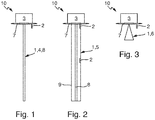
Fig. 1 : einen seitlichen Längsschnitt einer erfindungsgemäßen Vorrichtung mit einem Metallstab und einem Grenzstandsensor, -
Fig. 2 : einen seitlichen Längsschnitt einer erfindungsgemäßen Vorrichtung mit einer koaxialen Sonde und zwei Grenzstandsensoren, und -
Fig. 3 : einen seitlichen Längsschnitt einer erfindungsgemäßen Vorrichtung mit einer Radarantenne und einem Grenzstandsensor. -
Fig. 1 zeigt einen seitlichen Längsschnitt einer erfindungsgemäßen Vorrichtung 10. Die Vorrichtung 10 umfasst eine Elektronikeinheit 3, die an einer ersten Seitenfläche einer Platte 7 angeordnet ist. Auf der Platte 7 ist gegenüber der ersten Seitenfläche der Platte 7, eine zweite Seitenfläche angeordnet. An der zweiten Seitenfläche der Platte 7 ragt mittig ein Metallstab 8 heraus. Der Metallstab 8 ist zylinderförmig ausgestaltet. Ferner ist auf der zweiten Seitenfläche der Platte 7 ein Grenzstandsensor 2 angeordnet. Der Grenzstandsensor 2 ist seitlich zum Rand der zweiten Seitenfläche der Platte 7 angeordnet. - Der Metallstab 8 kann sowohl als TDR-Füllstandsensor zum Messen des Füllstands entsprechend der Zeitbereichsreflektometrie, als auch zur kapazitiven Füllstandsmessung verwendet werden. Bei einer kapazitiven Füllstandsmessung bildet der Metallstab 8 eine erste Elektrode, ein Behälter, in dem sich ein Füllgut befindet, eine zweite Elektrode und das Füllgut zwischen dem Metallstab 8 und dem Behälter ein Dielektrikum. Je höher der Füllstand des Füllguts ist, desto mehr Dielektrikum befindet sich zwischen dem Metallrohr 8 (erste Elektrode) und dem Behälter (zweite Elektrode). Werden der Metallstab 8 und der Behälter wie Elektroden eines Kondensators mit einer Wechselspannung der Elektronikeinheit 3 beaufschlagt, lässt sich aufgrund des Antwortsignals der Wechselspannung auf den Füllstand des Füllguts in dem Behälter schließen.
- Bei einem Betreiben des Metallstabs 8 als TDR-Füllstandsensor, erzeugt die Elektronikeinheit 3 einen elektrischen Puls und koppelt den elektrischen Puls in den Metallstab 8 ein. Ein Teil dieses elektrischen Pulses wird an der Oberfläche des Füllguts reflektiert und gelangt auf diese Weise über den Metallstab 8 zurück zur Elektronikeinheit 3. Aufgrund der Laufzeit des Pulses kann die Elektronikeinheit 3 den Füllstand des Füllguts in dem Behälter bestimmen.
- Erreicht der Füllstand den Grenzstandsensor 2, wird der Grenzstandsensor 2 von dem Füllgut bedeckt und der Grenzstandsensor 2 meldet den Zustand "Bedeckt" an die Elektronikeinheit 3.
-
Fig. 2 zeigt einen seitlichen Längsschnitt einer weiteren Ausgestaltung einer erfindungsgemäßen Vorrichtung 10. Die Vorrichtung 10 weist eine Elektronikeinheit 3 auf, die auf einer ersten Seitenfläche einer Platte 7 angeordnet ist. Auf einer zweiten Seitenfläche der Platte 7 ist ein Füllstandsensor 1 angeordnet, wobei der Füllstandsensor 1 als eine koaxiale Sonde 5 ausgebildet ist. Die koaxiale Sonde 5 ist als ein Metallstab 8, der mittig in einem Metallrohr 9 angeordnet ist, ausgebildet. Der Metallstab 8 und das Metallrohr 9 bilden zwei Elektroden und das Füllgut zwischen dem Metallstab 8 und das Metallrohr 9 bildet das Dielektrikum eines Kondensators, der abhängig von dem Füllstand des Füllguts seine Kapazität ändert. - Ein erster und ein zweiter Grenzstandsensor 2 sind an einer Außenfläche des Metallrohrs 9 angeordnet. Der erste Grenzstandsensor 2 ist an einem Ansatz des Metallrohrs 9 an der zweiten Seitenfläche der Platte 7 angeordnet und der zweite Grenzstandsensor 2 ist in der Mitte des Metallrohrs 9 angeordnet. Die zwei Grenzstandsensoren 2 können das Überschreiten des Grenzstandes des Füllguts an zwei verschiedenen Füllständen überwachen. Sobald der Füllstand des Füllguts eine der zwei Grenzstandsonden 2 erreicht, ist die jeweilige Grenzstandsonde 2 mit Füllgut bedeckt. Diese Grenzstandsonde 2 meldet den Zustand "Bedeckt" weiter an die Elektronikeinheit 3, wodurch ein weiteres Ansteigen des Füllguts verhindert werden kann. Mit Hilfe verteilter Grenzstandsensoren lassen sich kontinuierliche Messergebnisse zusätzlich plausibilisieren.
-
Fig. 3 zeigt einen seitlichen Längsschnitt eines dritten Ausführungsbeispiels einer erfindungsgemäßen Vorrichtung 10. Die Vorrichtung 10 weist eine Elektronikeinheit 3 an einer ersten Seitenfläche einer Platte 7 auf. Die zweite Seitenfläche der Platte 7 weist eine trichterförmige Radarantenne 6 auf, die als ein Füllstandsensor 1 fungiert. Die Radarantenne 6 sendet Radarwellen aus, die durch die trichterförmige Form in Richtung des Füllguts fokussiert werden. Treffen die Radarwellen auf die Oberfläche des Füllguts, werden sie reflektiert und von der Radarantenne 6 empfangen. Die Radarantenne 6 wandelt die empfangenen elektromagnetischen Wellen in elektrische Signale um und leitet diese an die Elektronikeinheit 3 weiter. Die Elektronikeinheit 3 bestimmt aus der Laufzeit der elektromagnetischen Wellen den Füllstand des Füllguts in dem Behälter. - Ein Grenzstandsensor 2 ist nahe dem Außenrand der zweiten Seitenfläche der Platte 7 angeordnet. Sobald der Füllstand des Füllguts die Grenzstandsonde 2 erreicht, wird diese vom Füllgut bedeckt und der Grenzstandsensor 2 meldet den Zustand "Bedeckt" an die Elektronikeinheit. Auf diese Weise kann ein weiteres Ansteigen des Füllguts verhindert werden.
-
- 1
- Füllstandsensor
- 2
- Grenzstandsensor
- 3
- Elektronikeinheit
- 4
- TDR-Füllstandsensor
- 5
- Koaxiale Sonde
- 6
- Radarantenne
- 7
- Platte
- 8
- Metallstab
- 9
- Metallrohr
- 10
- Vorrichtung
Claims (7)
- Vorrichtung zur Messung des Füllstands eines Füllguts in einem Behälter, umfassendeine Platte (7), mit einer ersten Seitenfläche und einer gegenüber der ersten Seitenfläche angeordneten zweiten Seitenfläche;einen an der ersten Seitenfläche der Platte (7) angeordneten Füllstandsensor (1), der so ausgebildet ist, dass er den Füllstand über ein Laufzeitdifferenz-Messverfahren oder ein kapazitives Messverfahren bestimmt,eine Elektronikeinheit (3), die an der zweiten Seitenfläche der Platte (7) angeordnet ist, und anhand der Messdaten des Füllstandsensors (1) den Füllstand des Füllguts in dem Behälter bestimmt,einen Grenzstandsensor (2) zum Überwachen eines Grenzstands des Füllguts in dem Behälter,wobei der Grenzstandsensor (2) an der ersten Seitenfläche der Platte (7) angeordnet ist,wobei die Elektronikeinheit (3) dem Füllstandsensor (1) und dem Grenzstandsensor (2) zugeordnet ist,und wobei die Elektronikeinheit (3) anhand der Messdaten des Grenzstandsensors (2) den Grenzstand des Füllguts in dem Behälter überwacht.
- Füllstandsmessgerät nach Anspruch 1,dadurch gekennzeichnet, dassder Füllstandsensor (1) als ein TDR-Füllstandsensor (4) zum Messen des Füllstands entsprechend der Zeitbereichsreflektometrie ausgestaltet ist.
- Füllstandsmessgerät nach Anspruch 2,dadurch gekennzeichnet, dassder Füllstandsensor (1) als ein Metallstab oder als ein Metallseil ausgestaltet ist.
- Füllstandsmessgerät nach Anspruch 1,dadurch gekennzeichnet, dassder Füllstandsensor (1) als eine koaxiale Sonde (5) zum kapazitiven Messen des Füllstands ausgestaltet ist.
- Füllstandsmessgerät nach Anspruch 1,dadurch gekennzeichnet, dassder Füllstandsensor (1) als eine Radarantenne (6) oder als Ultraschallsensor ausgestaltet sind.
- Füllstandsmessgerät nach mindestens einem der vorherigen Ansprüche,dadurch gekennzeichnet, dassder Grenzstandsensor als ein thermischer, resistiver, optischer oder kapazitiver Grenzstandsensor ausgestaltet ist.
- Füllstandsmessgerät nach mindestens einem der vorhergehenden Ansprüche,dadurch gekennzeichnet, dassder Grenzstandsensor (2) als ein Gassensor zum Bestimmen von Messgrößen der Umgebungsluft ausgestaltet ist.
Applications Claiming Priority (2)
| Application Number | Priority Date | Filing Date | Title |
|---|---|---|---|
| DE102013113766.0A DE102013113766A1 (de) | 2013-12-10 | 2013-12-10 | Vorrichtung zur Messung des Füllstands eines Füllguts in einem Behälter |
| PCT/EP2014/073522 WO2015086225A1 (de) | 2013-12-10 | 2014-11-03 | Vorrichtung zur messung des füllstands eines füllguts in einem behälter |
Publications (2)
| Publication Number | Publication Date |
|---|---|
| EP3080563A1 EP3080563A1 (de) | 2016-10-19 |
| EP3080563B1 true EP3080563B1 (de) | 2021-09-15 |
Family
ID=51845409
Family Applications (1)
| Application Number | Title | Priority Date | Filing Date |
|---|---|---|---|
| EP14792816.2A Active EP3080563B1 (de) | 2013-12-10 | 2014-11-03 | Vorrichtung zur messung des füllstands eines füllguts in einem behälter |
Country Status (5)
| Country | Link |
|---|---|
| US (1) | US20160313169A1 (de) |
| EP (1) | EP3080563B1 (de) |
| CN (1) | CN105849511A (de) |
| DE (1) | DE102013113766A1 (de) |
| WO (1) | WO2015086225A1 (de) |
Families Citing this family (9)
| Publication number | Priority date | Publication date | Assignee | Title |
|---|---|---|---|---|
| EP3073229B1 (de) * | 2015-03-27 | 2022-06-22 | VEGA Grieshaber KG | Radar-füllstandmessgerät mit integriertem grenzstandsensor |
| DE102016107808B4 (de) * | 2016-04-27 | 2022-03-31 | Tdk-Micronas Gmbh | Verfahren und Anordnung zur Überwachung eines Zustands |
| US10712309B2 (en) * | 2016-12-22 | 2020-07-14 | Endress+Hauser Conducta Gmbh+Co. Kg | Electrochemical sensor |
| DE102019112933A1 (de) * | 2019-05-16 | 2020-11-19 | Endress+Hauser SE+Co. KG | Feldgerät der Automatisierungstechnik für einen Einsatz in explosionsgefährdeten Bereichen, Verfahren zur Überwachung der Gasdichtheit in einem Feldgerät und Verfahren zur Herstellung eines ebensolchen Feldgeräts |
| DE102020114636A1 (de) | 2020-06-02 | 2021-12-02 | Vega Grieshaber Kg | Integrierter Sensor zur Erfassung eines minimalen Grenzstandes und eines Füllstandes, Anordnung eines solchen Sensors an einem Behälter und Verfahren zum Betreiben eines solchen Sensors |
| DE102021113925A1 (de) | 2021-05-28 | 2022-12-01 | Vega Grieshaber Kg | Füll- oder Grenzstandsensor mit optischer Überwachungseinrichtung |
| DE102021115755A1 (de) | 2021-06-17 | 2022-12-22 | Vega Grieshaber Kg | Sensorhalter und Messanordnung mit flexibler Behälterverbindung und/oder Sensoraufnahme |
| DE102021115756A1 (de) | 2021-06-17 | 2022-12-22 | Vega Grieshaber Kg | Messanordnung mit Befestigungseinrichtung zur Befestigung an einem Hohlraum |
| DE102021128333A1 (de) | 2021-10-29 | 2023-05-04 | Vega Grieshaber Kg | Feldgerät mit graphischer Visualisierung der Prozessgröße |
Family Cites Families (13)
| Publication number | Priority date | Publication date | Assignee | Title |
|---|---|---|---|---|
| DE4405238C2 (de) * | 1994-02-18 | 1998-07-09 | Endress Hauser Gmbh Co | Anordnung zur Messung des Füllstands in einem Behälter |
| JP2741344B2 (ja) * | 1994-07-22 | 1998-04-15 | 大同メタル工業株式会社 | 超音波処理装置 |
| CN1156821A (zh) * | 1996-04-24 | 1997-08-13 | 刘志超 | 热导式液位测量控制器 |
| US6672155B2 (en) * | 2000-10-14 | 2004-01-06 | Endress + Hauser Gmbh + Co. | Apparatus for determining the filling level of a filling material in a container |
| RU2342639C2 (ru) * | 2002-08-13 | 2008-12-27 | Вега Грисхабер Кг | Система для изготовления имеющего модульную конструкцию устройства для определения физической величины в технологическом процессе и унифицированные компоненты |
| DE10355784A1 (de) * | 2003-06-17 | 2005-02-03 | Endress + Hauser Gmbh + Co. Kg | Vorrichtung zur Überwachung eines Feldgeräts |
| EP1507133B1 (de) * | 2003-06-17 | 2016-06-29 | Endress + Hauser GmbH + Co. KG | Vorrichtung zur Überwachung eines Feldgeräts |
| DE102006016381A1 (de) * | 2006-04-05 | 2007-10-18 | Endress + Hauser Gmbh + Co. Kg | Messvorrichtung zur Bestimmung und/oder Überwachung einer Prozessgröße, entsprechende Auswertevorrichtung und Anlage |
| DE102006051102A1 (de) * | 2006-10-25 | 2008-04-30 | Endress + Hauser Gmbh + Co. Kg | Prozessautomatisierungssystem zur Bestimmung, zur Überwachung und/oder zum Beeinflussen von unterschiedlichen Prozessgröße und/oder Zustandsgrößen |
| DE102008043252A1 (de) * | 2008-10-29 | 2010-05-06 | Endress + Hauser Gmbh + Co. Kg | Füllstandsmessgerät |
| US8018373B2 (en) * | 2008-12-19 | 2011-09-13 | Rosemount Tank Radar Ab | System and method for filling level determination |
| DE102010038732B4 (de) * | 2010-07-30 | 2023-07-27 | Endress+Hauser SE+Co. KG | Vorrichtung und Verfahren zur Sicherung der Befestigung eines koaxial um eine Messsonde angeordneten Rohres einer Messsondeneinheit eines Füllstandsmessgerätes an einem Prozessanschlusselement |
| DE102010064394A1 (de) * | 2010-12-30 | 2012-07-05 | Endress + Hauser Gmbh + Co. Kg | Verfahren und Vorrichtung zum Ausrichten eines Messgerätes |
-
2013
- 2013-12-10 DE DE102013113766.0A patent/DE102013113766A1/de not_active Withdrawn
-
2014
- 2014-11-03 WO PCT/EP2014/073522 patent/WO2015086225A1/de active Application Filing
- 2014-11-03 EP EP14792816.2A patent/EP3080563B1/de active Active
- 2014-11-03 CN CN201480067522.1A patent/CN105849511A/zh active Pending
- 2014-11-03 US US15/100,767 patent/US20160313169A1/en not_active Abandoned
Also Published As
| Publication number | Publication date |
|---|---|
| WO2015086225A1 (de) | 2015-06-18 |
| CN105849511A (zh) | 2016-08-10 |
| EP3080563A1 (de) | 2016-10-19 |
| DE102013113766A1 (de) | 2015-06-11 |
| US20160313169A1 (en) | 2016-10-27 |
Similar Documents
| Publication | Publication Date | Title |
|---|---|---|
| EP3080563B1 (de) | Vorrichtung zur messung des füllstands eines füllguts in einem behälter | |
| EP1305581A1 (de) | Vorrichtung zur messung des füllstands eines füllguts in einem behälter | |
| EP2962074B1 (de) | Verfahren und vorrichtung zur überwachung eines vorgegebenen füllstands eines mediums in einem behälter | |
| EP2994725B1 (de) | Verfahren und vorrichtung zur überwachung zumindest einer medienspezifischen eigenschaft eines mediums für eine füllstandsmessung | |
| EP2519807B1 (de) | Einrichtung zum erkennen eines pegelstands | |
| EP2598848B1 (de) | Vorrichtung zur bestimmung und/oder überwachung eines vorgegebenen füllstands | |
| EP1597544B1 (de) | Vorrichtung zur bestimmung und/oder überwachung des füllstands eines mediums in einem behälter | |
| EP1972905B1 (de) | Füllstandsmessvorrichtung | |
| EP1899689B1 (de) | Vorrichtung zur kapazitiven bestimmung und/oder überwachung des füllstandes | |
| EP3073229B1 (de) | Radar-füllstandmessgerät mit integriertem grenzstandsensor | |
| EP2400275A1 (de) | Berührungslose Füllstandsmessung von Flüssigkeiten | |
| EP3390981B1 (de) | Sensoradapter | |
| DE102007060579A1 (de) | Verfahren zur Ermittlung und/oder zur Beurteilung des Befüllzustands eines mit zumindest einem Medium gefüllten Behälter | |
| DE102010038732A1 (de) | Vorrichtung und Verfahren zur Sicherung der Befestigung des koaxial um die Messsonde angeordnete Rohres einer Messsondeneinheit des Füllstandsmessgerät an einem Prozessanschlusselement | |
| EP3312571B1 (de) | Impedanzgrenzschalter mit zusätzlicher schirmelektrode | |
| DE102012014267A1 (de) | Verfahren zur Zustandsüberwachung eines nach dem Radar-Prinzip arbeitenden Füllstandmessgeräts und entsprechendes Füllstandmessgerät | |
| EP1128169A1 (de) | Verfahren und Vorrichtung zur Bestimmung des Grenzfüllstandes eines Füllguts in einem Behälter | |
| EP1083412A1 (de) | Vorrichtung zur Bestimmung einer physikalischen Grösse eines flüssigen oder festen Mediums | |
| EP1456612B1 (de) | Verfahren zur bestimmung und/oder überwachung einer physikalischen oder chemischen prozessgrösse | |
| DE102016214387B4 (de) | Verfahren zum Betreiben eines kapazitiven Füllstandsgrenzschalters und kapazitiver Füllstandsgrenzschalter | |
| DE10309769B4 (de) | Anordnung zur Bestimmung von Zustandsgrößen für Flüssigkeiten in einem geschlossenen nichtmetallischen Behälter | |
| WO2020020534A1 (de) | Überprüfung der qualität einer fluidkonzentration | |
| EP4134637B1 (de) | Kapazitive füllstandsonde ohne totbereich | |
| WO2006000378A2 (de) | Berührungslose kapazitive füllstandsmessung | |
| DE102015202448A1 (de) | Auswerteverfahren für einen TDR-Grenzstandschalter |
Legal Events
| Date | Code | Title | Description |
|---|---|---|---|
| PUAI | Public reference made under article 153(3) epc to a published international application that has entered the european phase |
Free format text: ORIGINAL CODE: 0009012 |
|
| STAA | Information on the status of an ep patent application or granted ep patent |
Free format text: STATUS: REQUEST FOR EXAMINATION WAS MADE |
|
| 17P | Request for examination filed |
Effective date: 20160523 |
|
| AK | Designated contracting states |
Kind code of ref document: A1 Designated state(s): AL AT BE BG CH CY CZ DE DK EE ES FI FR GB GR HR HU IE IS IT LI LT LU LV MC MK MT NL NO PL PT RO RS SE SI SK SM TR |
|
| AX | Request for extension of the european patent |
Extension state: BA ME |
|
| DAX | Request for extension of the european patent (deleted) | ||
| RAP1 | Party data changed (applicant data changed or rights of an application transferred) |
Owner name: ENDRESS+HAUSER SE+CO. KG |
|
| GRAP | Despatch of communication of intention to grant a patent |
Free format text: ORIGINAL CODE: EPIDOSNIGR1 |
|
| STAA | Information on the status of an ep patent application or granted ep patent |
Free format text: STATUS: GRANT OF PATENT IS INTENDED |
|
| INTG | Intention to grant announced |
Effective date: 20210611 |
|
| GRAS | Grant fee paid |
Free format text: ORIGINAL CODE: EPIDOSNIGR3 |
|
| GRAA | (expected) grant |
Free format text: ORIGINAL CODE: 0009210 |
|
| STAA | Information on the status of an ep patent application or granted ep patent |
Free format text: STATUS: THE PATENT HAS BEEN GRANTED |
|
| AK | Designated contracting states |
Kind code of ref document: B1 Designated state(s): AL AT BE BG CH CY CZ DE DK EE ES FI FR GB GR HR HU IE IS IT LI LT LU LV MC MK MT NL NO PL PT RO RS SE SI SK SM TR |
|
| REG | Reference to a national code |
Ref country code: GB Ref legal event code: FG4D Free format text: NOT ENGLISH Ref country code: CH Ref legal event code: EP |
|
| REG | Reference to a national code |
Ref country code: DE Ref legal event code: R096 Ref document number: 502014015880 Country of ref document: DE |
|
| REG | Reference to a national code |
Ref country code: IE Ref legal event code: FG4D Free format text: LANGUAGE OF EP DOCUMENT: GERMAN |
|
| REG | Reference to a national code |
Ref country code: AT Ref legal event code: REF Ref document number: 1430844 Country of ref document: AT Kind code of ref document: T Effective date: 20211015 |
|
| REG | Reference to a national code |
Ref country code: LT Ref legal event code: MG9D |
|
| REG | Reference to a national code |
Ref country code: NL Ref legal event code: MP Effective date: 20210915 |
|
| PG25 | Lapsed in a contracting state [announced via postgrant information from national office to epo] |
Ref country code: LT Free format text: LAPSE BECAUSE OF FAILURE TO SUBMIT A TRANSLATION OF THE DESCRIPTION OR TO PAY THE FEE WITHIN THE PRESCRIBED TIME-LIMIT Effective date: 20210915 Ref country code: BG Free format text: LAPSE BECAUSE OF FAILURE TO SUBMIT A TRANSLATION OF THE DESCRIPTION OR TO PAY THE FEE WITHIN THE PRESCRIBED TIME-LIMIT Effective date: 20211215 Ref country code: FI Free format text: LAPSE BECAUSE OF FAILURE TO SUBMIT A TRANSLATION OF THE DESCRIPTION OR TO PAY THE FEE WITHIN THE PRESCRIBED TIME-LIMIT Effective date: 20210915 Ref country code: NO Free format text: LAPSE BECAUSE OF FAILURE TO SUBMIT A TRANSLATION OF THE DESCRIPTION OR TO PAY THE FEE WITHIN THE PRESCRIBED TIME-LIMIT Effective date: 20211215 Ref country code: RS Free format text: LAPSE BECAUSE OF FAILURE TO SUBMIT A TRANSLATION OF THE DESCRIPTION OR TO PAY THE FEE WITHIN THE PRESCRIBED TIME-LIMIT Effective date: 20210915 Ref country code: SE Free format text: LAPSE BECAUSE OF FAILURE TO SUBMIT A TRANSLATION OF THE DESCRIPTION OR TO PAY THE FEE WITHIN THE PRESCRIBED TIME-LIMIT Effective date: 20210915 Ref country code: HR Free format text: LAPSE BECAUSE OF FAILURE TO SUBMIT A TRANSLATION OF THE DESCRIPTION OR TO PAY THE FEE WITHIN THE PRESCRIBED TIME-LIMIT Effective date: 20210915 |
|
| PG25 | Lapsed in a contracting state [announced via postgrant information from national office to epo] |
Ref country code: LV Free format text: LAPSE BECAUSE OF FAILURE TO SUBMIT A TRANSLATION OF THE DESCRIPTION OR TO PAY THE FEE WITHIN THE PRESCRIBED TIME-LIMIT Effective date: 20210915 Ref country code: GR Free format text: LAPSE BECAUSE OF FAILURE TO SUBMIT A TRANSLATION OF THE DESCRIPTION OR TO PAY THE FEE WITHIN THE PRESCRIBED TIME-LIMIT Effective date: 20211216 |
|
| PG25 | Lapsed in a contracting state [announced via postgrant information from national office to epo] |
Ref country code: IS Free format text: LAPSE BECAUSE OF FAILURE TO SUBMIT A TRANSLATION OF THE DESCRIPTION OR TO PAY THE FEE WITHIN THE PRESCRIBED TIME-LIMIT Effective date: 20220115 Ref country code: SM Free format text: LAPSE BECAUSE OF FAILURE TO SUBMIT A TRANSLATION OF THE DESCRIPTION OR TO PAY THE FEE WITHIN THE PRESCRIBED TIME-LIMIT Effective date: 20210915 Ref country code: SK Free format text: LAPSE BECAUSE OF FAILURE TO SUBMIT A TRANSLATION OF THE DESCRIPTION OR TO PAY THE FEE WITHIN THE PRESCRIBED TIME-LIMIT Effective date: 20210915 Ref country code: RO Free format text: LAPSE BECAUSE OF FAILURE TO SUBMIT A TRANSLATION OF THE DESCRIPTION OR TO PAY THE FEE WITHIN THE PRESCRIBED TIME-LIMIT Effective date: 20210915 Ref country code: PT Free format text: LAPSE BECAUSE OF FAILURE TO SUBMIT A TRANSLATION OF THE DESCRIPTION OR TO PAY THE FEE WITHIN THE PRESCRIBED TIME-LIMIT Effective date: 20220117 Ref country code: PL Free format text: LAPSE BECAUSE OF FAILURE TO SUBMIT A TRANSLATION OF THE DESCRIPTION OR TO PAY THE FEE WITHIN THE PRESCRIBED TIME-LIMIT Effective date: 20210915 Ref country code: NL Free format text: LAPSE BECAUSE OF FAILURE TO SUBMIT A TRANSLATION OF THE DESCRIPTION OR TO PAY THE FEE WITHIN THE PRESCRIBED TIME-LIMIT Effective date: 20210915 Ref country code: ES Free format text: LAPSE BECAUSE OF FAILURE TO SUBMIT A TRANSLATION OF THE DESCRIPTION OR TO PAY THE FEE WITHIN THE PRESCRIBED TIME-LIMIT Effective date: 20210915 Ref country code: EE Free format text: LAPSE BECAUSE OF FAILURE TO SUBMIT A TRANSLATION OF THE DESCRIPTION OR TO PAY THE FEE WITHIN THE PRESCRIBED TIME-LIMIT Effective date: 20210915 Ref country code: CZ Free format text: LAPSE BECAUSE OF FAILURE TO SUBMIT A TRANSLATION OF THE DESCRIPTION OR TO PAY THE FEE WITHIN THE PRESCRIBED TIME-LIMIT Effective date: 20210915 Ref country code: AL Free format text: LAPSE BECAUSE OF FAILURE TO SUBMIT A TRANSLATION OF THE DESCRIPTION OR TO PAY THE FEE WITHIN THE PRESCRIBED TIME-LIMIT Effective date: 20210915 |
|
| REG | Reference to a national code |
Ref country code: DE Ref legal event code: R097 Ref document number: 502014015880 Country of ref document: DE |
|
| PG25 | Lapsed in a contracting state [announced via postgrant information from national office to epo] |
Ref country code: MC Free format text: LAPSE BECAUSE OF FAILURE TO SUBMIT A TRANSLATION OF THE DESCRIPTION OR TO PAY THE FEE WITHIN THE PRESCRIBED TIME-LIMIT Effective date: 20210915 |
|
| REG | Reference to a national code |
Ref country code: CH Ref legal event code: PL |
|
| PLBE | No opposition filed within time limit |
Free format text: ORIGINAL CODE: 0009261 |
|
| STAA | Information on the status of an ep patent application or granted ep patent |
Free format text: STATUS: NO OPPOSITION FILED WITHIN TIME LIMIT |
|
| PG25 | Lapsed in a contracting state [announced via postgrant information from national office to epo] |
Ref country code: LU Free format text: LAPSE BECAUSE OF NON-PAYMENT OF DUE FEES Effective date: 20211103 Ref country code: DK Free format text: LAPSE BECAUSE OF FAILURE TO SUBMIT A TRANSLATION OF THE DESCRIPTION OR TO PAY THE FEE WITHIN THE PRESCRIBED TIME-LIMIT Effective date: 20210915 Ref country code: BE Free format text: LAPSE BECAUSE OF NON-PAYMENT OF DUE FEES Effective date: 20211130 |
|
| REG | Reference to a national code |
Ref country code: BE Ref legal event code: MM Effective date: 20211130 |
|
| 26N | No opposition filed |
Effective date: 20220616 |
|
| GBPC | Gb: european patent ceased through non-payment of renewal fee |
Effective date: 20211215 |
|
| PG25 | Lapsed in a contracting state [announced via postgrant information from national office to epo] |
Ref country code: SI Free format text: LAPSE BECAUSE OF FAILURE TO SUBMIT A TRANSLATION OF THE DESCRIPTION OR TO PAY THE FEE WITHIN THE PRESCRIBED TIME-LIMIT Effective date: 20210915 |
|
| PG25 | Lapsed in a contracting state [announced via postgrant information from national office to epo] |
Ref country code: IE Free format text: LAPSE BECAUSE OF NON-PAYMENT OF DUE FEES Effective date: 20211103 Ref country code: GB Free format text: LAPSE BECAUSE OF NON-PAYMENT OF DUE FEES Effective date: 20211215 |
|
| PG25 | Lapsed in a contracting state [announced via postgrant information from national office to epo] |
Ref country code: FR Free format text: LAPSE BECAUSE OF NON-PAYMENT OF DUE FEES Effective date: 20211115 |
|
| REG | Reference to a national code |
Ref country code: AT Ref legal event code: MM01 Ref document number: 1430844 Country of ref document: AT Kind code of ref document: T Effective date: 20211103 |
|
| PG25 | Lapsed in a contracting state [announced via postgrant information from national office to epo] |
Ref country code: IT Free format text: LAPSE BECAUSE OF FAILURE TO SUBMIT A TRANSLATION OF THE DESCRIPTION OR TO PAY THE FEE WITHIN THE PRESCRIBED TIME-LIMIT Effective date: 20210915 Ref country code: AT Free format text: LAPSE BECAUSE OF NON-PAYMENT OF DUE FEES Effective date: 20211103 |
|
| PG25 | Lapsed in a contracting state [announced via postgrant information from national office to epo] |
Ref country code: HU Free format text: LAPSE BECAUSE OF FAILURE TO SUBMIT A TRANSLATION OF THE DESCRIPTION OR TO PAY THE FEE WITHIN THE PRESCRIBED TIME-LIMIT; INVALID AB INITIO Effective date: 20141103 |
|
| PG25 | Lapsed in a contracting state [announced via postgrant information from national office to epo] |
Ref country code: CY Free format text: LAPSE BECAUSE OF FAILURE TO SUBMIT A TRANSLATION OF THE DESCRIPTION OR TO PAY THE FEE WITHIN THE PRESCRIBED TIME-LIMIT Effective date: 20210915 |
|
| P01 | Opt-out of the competence of the unified patent court (upc) registered |
Effective date: 20230601 |
|
| PG25 | Lapsed in a contracting state [announced via postgrant information from national office to epo] |
Ref country code: LI Free format text: LAPSE BECAUSE OF NON-PAYMENT OF DUE FEES Effective date: 20220630 Ref country code: CH Free format text: LAPSE BECAUSE OF NON-PAYMENT OF DUE FEES Effective date: 20220630 |
|
| PGFP | Annual fee paid to national office [announced via postgrant information from national office to epo] |
Ref country code: DE Payment date: 20231121 Year of fee payment: 10 |
|
| PG25 | Lapsed in a contracting state [announced via postgrant information from national office to epo] |
Ref country code: MK Free format text: LAPSE BECAUSE OF FAILURE TO SUBMIT A TRANSLATION OF THE DESCRIPTION OR TO PAY THE FEE WITHIN THE PRESCRIBED TIME-LIMIT Effective date: 20210915 |