EP3080560B1 - Dichte-messgerät - Google Patents
Dichte-messgerät Download PDFInfo
- Publication number
- EP3080560B1 EP3080560B1 EP14793095.2A EP14793095A EP3080560B1 EP 3080560 B1 EP3080560 B1 EP 3080560B1 EP 14793095 A EP14793095 A EP 14793095A EP 3080560 B1 EP3080560 B1 EP 3080560B1
- Authority
- EP
- European Patent Office
- Prior art keywords
- measuring
- vibration
- frequency
- measuring tube
- signal
- Prior art date
- Legal status (The legal status is an assumption and is not a legal conclusion. Google has not performed a legal analysis and makes no representation as to the accuracy of the status listed.)
- Active
Links
- 230000005284 excitation Effects 0.000 claims description 90
- 230000010363 phase shift Effects 0.000 claims description 54
- 230000033001 locomotion Effects 0.000 claims description 33
- 230000004044 response Effects 0.000 claims description 24
- 230000000737 periodic effect Effects 0.000 claims description 11
- RTAQQCXQSZGOHL-UHFFFAOYSA-N Titanium Chemical compound [Ti] RTAQQCXQSZGOHL-UHFFFAOYSA-N 0.000 claims description 8
- 239000010936 titanium Substances 0.000 claims description 8
- 229910052719 titanium Inorganic materials 0.000 claims description 8
- 229910052710 silicon Inorganic materials 0.000 claims description 4
- 239000010703 silicon Substances 0.000 claims description 4
- 238000013461 design Methods 0.000 claims description 3
- 230000005502 phase rule Effects 0.000 claims 8
- 238000005259 measurement Methods 0.000 description 102
- 230000010355 oscillation Effects 0.000 description 64
- 230000000875 corresponding effect Effects 0.000 description 46
- 238000005452 bending Methods 0.000 description 27
- 230000001419 dependent effect Effects 0.000 description 19
- 238000013016 damping Methods 0.000 description 18
- 238000011156 evaluation Methods 0.000 description 16
- 238000000034 method Methods 0.000 description 15
- 230000008569 process Effects 0.000 description 14
- 230000008878 coupling Effects 0.000 description 12
- 238000010168 coupling process Methods 0.000 description 12
- 238000005859 coupling reaction Methods 0.000 description 12
- 238000001739 density measurement Methods 0.000 description 12
- 238000012545 processing Methods 0.000 description 9
- 238000004364 calculation method Methods 0.000 description 8
- 239000003990 capacitor Substances 0.000 description 8
- 238000010586 diagram Methods 0.000 description 8
- 230000005520 electrodynamics Effects 0.000 description 8
- 230000008859 change Effects 0.000 description 7
- PXHVJJICTQNCMI-UHFFFAOYSA-N Nickel Chemical compound [Ni] PXHVJJICTQNCMI-UHFFFAOYSA-N 0.000 description 6
- QCWXUUIWCKQGHC-UHFFFAOYSA-N Zirconium Chemical compound [Zr] QCWXUUIWCKQGHC-UHFFFAOYSA-N 0.000 description 6
- 229910045601 alloy Inorganic materials 0.000 description 6
- 239000000956 alloy Substances 0.000 description 6
- 238000005516 engineering process Methods 0.000 description 6
- 239000010935 stainless steel Substances 0.000 description 6
- 229910001220 stainless steel Inorganic materials 0.000 description 6
- 229910052726 zirconium Inorganic materials 0.000 description 6
- 230000006399 behavior Effects 0.000 description 5
- 238000004891 communication Methods 0.000 description 5
- 230000006870 function Effects 0.000 description 5
- 229910052715 tantalum Inorganic materials 0.000 description 5
- GUVRBAGPIYLISA-UHFFFAOYSA-N tantalum atom Chemical compound [Ta] GUVRBAGPIYLISA-UHFFFAOYSA-N 0.000 description 5
- 230000005540 biological transmission Effects 0.000 description 4
- 238000009529 body temperature measurement Methods 0.000 description 4
- 238000006243 chemical reaction Methods 0.000 description 4
- 230000001143 conditioned effect Effects 0.000 description 4
- 238000012937 correction Methods 0.000 description 4
- 238000009826 distribution Methods 0.000 description 4
- 239000007789 gas Substances 0.000 description 4
- 239000007788 liquid Substances 0.000 description 4
- 238000012423 maintenance Methods 0.000 description 4
- 230000001105 regulatory effect Effects 0.000 description 4
- 238000004422 calculation algorithm Methods 0.000 description 3
- 230000007423 decrease Effects 0.000 description 3
- 229910052751 metal Inorganic materials 0.000 description 3
- 239000002184 metal Substances 0.000 description 3
- 229910052759 nickel Inorganic materials 0.000 description 3
- 230000003534 oscillatory effect Effects 0.000 description 3
- 230000002829 reductive effect Effects 0.000 description 3
- PEDCQBHIVMGVHV-UHFFFAOYSA-N Glycerine Chemical compound OCC(O)CO PEDCQBHIVMGVHV-UHFFFAOYSA-N 0.000 description 2
- 229910000831 Steel Inorganic materials 0.000 description 2
- 229910001362 Ta alloys Inorganic materials 0.000 description 2
- 229910001069 Ti alloy Inorganic materials 0.000 description 2
- 229910001093 Zr alloy Inorganic materials 0.000 description 2
- 230000033228 biological regulation Effects 0.000 description 2
- 239000004020 conductor Substances 0.000 description 2
- 230000000694 effects Effects 0.000 description 2
- 230000005484 gravity Effects 0.000 description 2
- 230000003993 interaction Effects 0.000 description 2
- 239000000463 material Substances 0.000 description 2
- BASFCYQUMIYNBI-UHFFFAOYSA-N platinum Chemical compound [Pt] BASFCYQUMIYNBI-UHFFFAOYSA-N 0.000 description 2
- 239000000047 product Substances 0.000 description 2
- 230000001681 protective effect Effects 0.000 description 2
- 230000011664 signaling Effects 0.000 description 2
- 239000010959 steel Substances 0.000 description 2
- 230000004936 stimulating effect Effects 0.000 description 2
- XLYOFNOQVPJJNP-UHFFFAOYSA-N water Substances O XLYOFNOQVPJJNP-UHFFFAOYSA-N 0.000 description 2
- 229910000915 Free machining steel Inorganic materials 0.000 description 1
- 229910000746 Structural steel Inorganic materials 0.000 description 1
- 230000009471 action Effects 0.000 description 1
- 230000001276 controlling effect Effects 0.000 description 1
- 230000002596 correlated effect Effects 0.000 description 1
- 230000001934 delay Effects 0.000 description 1
- 238000011161 development Methods 0.000 description 1
- 230000018109 developmental process Effects 0.000 description 1
- 238000007599 discharging Methods 0.000 description 1
- 230000005489 elastic deformation Effects 0.000 description 1
- 238000004146 energy storage Methods 0.000 description 1
- 238000007572 expansion measurement Methods 0.000 description 1
- 230000009969 flowable effect Effects 0.000 description 1
- 239000012530 fluid Substances 0.000 description 1
- 239000011521 glass Substances 0.000 description 1
- 235000011187 glycerol Nutrition 0.000 description 1
- 230000006872 improvement Effects 0.000 description 1
- 238000011835 investigation Methods 0.000 description 1
- 230000002427 irreversible effect Effects 0.000 description 1
- 230000002045 lasting effect Effects 0.000 description 1
- 230000007257 malfunction Effects 0.000 description 1
- 238000004519 manufacturing process Methods 0.000 description 1
- 238000010327 methods by industry Methods 0.000 description 1
- 238000012544 monitoring process Methods 0.000 description 1
- 239000002245 particle Substances 0.000 description 1
- 229910052697 platinum Inorganic materials 0.000 description 1
- 238000004382 potting Methods 0.000 description 1
- 238000004886 process control Methods 0.000 description 1
- 238000011084 recovery Methods 0.000 description 1
- 230000009467 reduction Effects 0.000 description 1
- 230000002441 reversible effect Effects 0.000 description 1
- 239000011265 semifinished product Substances 0.000 description 1
- 230000035945 sensitivity Effects 0.000 description 1
- 230000008054 signal transmission Effects 0.000 description 1
- 238000004088 simulation Methods 0.000 description 1
- 239000007787 solid Substances 0.000 description 1
- 230000003068 static effect Effects 0.000 description 1
- 230000002123 temporal effect Effects 0.000 description 1
- 238000012360 testing method Methods 0.000 description 1
- 238000012546 transfer Methods 0.000 description 1
Images


Classifications
-
- G—PHYSICS
- G01—MEASURING; TESTING
- G01F—MEASURING VOLUME, VOLUME FLOW, MASS FLOW OR LIQUID LEVEL; METERING BY VOLUME
- G01F1/00—Measuring the volume flow or mass flow of fluid or fluent solid material wherein the fluid passes through a meter in a continuous flow
- G01F1/76—Devices for measuring mass flow of a fluid or a fluent solid material
- G01F1/78—Direct mass flowmeters
- G01F1/80—Direct mass flowmeters operating by measuring pressure, force, momentum, or frequency of a fluid flow to which a rotational movement has been imparted
- G01F1/84—Coriolis or gyroscopic mass flowmeters
- G01F1/845—Coriolis or gyroscopic mass flowmeters arrangements of measuring means, e.g., of measuring conduits
- G01F1/8468—Coriolis or gyroscopic mass flowmeters arrangements of measuring means, e.g., of measuring conduits vibrating measuring conduits
- G01F1/8472—Coriolis or gyroscopic mass flowmeters arrangements of measuring means, e.g., of measuring conduits vibrating measuring conduits having curved measuring conduits, i.e. whereby the measuring conduits' curved center line lies within a plane
-
- G—PHYSICS
- G01—MEASURING; TESTING
- G01N—INVESTIGATING OR ANALYSING MATERIALS BY DETERMINING THEIR CHEMICAL OR PHYSICAL PROPERTIES
- G01N9/00—Investigating density or specific gravity of materials; Analysing materials by determining density or specific gravity
- G01N9/002—Investigating density or specific gravity of materials; Analysing materials by determining density or specific gravity using variation of the resonant frequency of an element vibrating in contact with the material submitted to analysis
-
- G—PHYSICS
- G01—MEASURING; TESTING
- G01F—MEASURING VOLUME, VOLUME FLOW, MASS FLOW OR LIQUID LEVEL; METERING BY VOLUME
- G01F1/00—Measuring the volume flow or mass flow of fluid or fluent solid material wherein the fluid passes through a meter in a continuous flow
- G01F1/76—Devices for measuring mass flow of a fluid or a fluent solid material
- G01F1/78—Direct mass flowmeters
- G01F1/80—Direct mass flowmeters operating by measuring pressure, force, momentum, or frequency of a fluid flow to which a rotational movement has been imparted
- G01F1/84—Coriolis or gyroscopic mass flowmeters
- G01F1/845—Coriolis or gyroscopic mass flowmeters arrangements of measuring means, e.g., of measuring conduits
- G01F1/8468—Coriolis or gyroscopic mass flowmeters arrangements of measuring means, e.g., of measuring conduits vibrating measuring conduits
-
- G—PHYSICS
- G01—MEASURING; TESTING
- G01N—INVESTIGATING OR ANALYSING MATERIALS BY DETERMINING THEIR CHEMICAL OR PHYSICAL PROPERTIES
- G01N11/00—Investigating flow properties of materials, e.g. viscosity, plasticity; Analysing materials by determining flow properties
- G01N11/02—Investigating flow properties of materials, e.g. viscosity, plasticity; Analysing materials by determining flow properties by measuring flow of the material
-
- G—PHYSICS
- G01—MEASURING; TESTING
- G01N—INVESTIGATING OR ANALYSING MATERIALS BY DETERMINING THEIR CHEMICAL OR PHYSICAL PROPERTIES
- G01N11/00—Investigating flow properties of materials, e.g. viscosity, plasticity; Analysing materials by determining flow properties
- G01N11/10—Investigating flow properties of materials, e.g. viscosity, plasticity; Analysing materials by determining flow properties by moving a body within the material
- G01N11/16—Investigating flow properties of materials, e.g. viscosity, plasticity; Analysing materials by determining flow properties by moving a body within the material by measuring damping effect upon oscillatory body
-
- G—PHYSICS
- G01—MEASURING; TESTING
- G01N—INVESTIGATING OR ANALYSING MATERIALS BY DETERMINING THEIR CHEMICAL OR PHYSICAL PROPERTIES
- G01N9/00—Investigating density or specific gravity of materials; Analysing materials by determining density or specific gravity
- G01N9/002—Investigating density or specific gravity of materials; Analysing materials by determining density or specific gravity using variation of the resonant frequency of an element vibrating in contact with the material submitted to analysis
- G01N2009/006—Investigating density or specific gravity of materials; Analysing materials by determining density or specific gravity using variation of the resonant frequency of an element vibrating in contact with the material submitted to analysis vibrating tube, tuning fork
Definitions
- the invention relates to a vibronic density measuring device for measuring a density, p, of a flowable medium, in particular a fluid flowing in a pipeline.
- Such density measuring devices for example designed as so-called four-wire or so-called two-wire devices - have been known for a long time, not least in the form of Coriolis mass flow / density measuring devices or also in the form of viscosity-density measuring devices, and are established in industrial use .
- Examples of such vibronic density measuring devices or measuring transducers suitable for them are, inter alia, in US-A 2004/0123645 , the US-A 2006/0096390 , the US-A 2007/0119264 , the US-A 2008/0047362 , the US-A 2008/0190195 , the US-A 2010/0005887 , the US-A 2010/0011882 , the US-A 2010/0257943 , the US-A 2011/0161017 , the US-A 2011/0219872 , the US-A 2011/0265580 , the US-A 2012/0123705 , the US-A 44 91 009 , the US-A 45 24 610 , the US-A 48 01 897 , the US-A 49 96 871 , the US-A 50 24 104 , the US-A 52 87 754 , the US-A 52 91 792 , the US-A 53 49 872 , the US-A 55 31 126
- the transducer of each of the density measuring devices shown therein comprises at least one at least partially straight and / or at least partially curved, for example U-, V-, S-, Z- or ⁇ -shaped, measuring tube with a lumen surrounded by a pipe wall for guiding the medium, said pipe wall - depending on the use - typically made of a metal, such as titanium or a titanium alloy, tantalum or a tantalum alloy, zirconium or a zirconium alloy, a stainless steel or a nickel-based alloy, or for example also consist of silicon and a caliber of the same measuring tube - depending on the use - can typically be in a range between 0.5 mm and 100 mm.
- a metal such as titanium or a titanium alloy, tantalum or a tantalum alloy, zirconium or a zirconium alloy, a stainless steel or a nickel-based alloy, or for example also consist of silicon and a caliber of the same measuring tube - depending on the use - can typically be
- the at least one measuring tube of such a transducer is set up to guide medium in the lumen and to be allowed to vibrate in the meantime in such a way that there are useful vibrations, namely mechanical vibrations around a position of rest with a also determined by the density of the medium, i.e. as a measure of the density usable usable frequency.
- useful vibrations namely mechanical vibrations around a position of rest with a also determined by the density of the medium, i.e. as a measure of the density usable usable frequency.
- bending vibrations at a natural resonance frequency are typically used as useful vibrations, for example those bending vibrations that correspond to a fundamental natural bending vibration mode inherent in the transducer, in which the vibrations of the measuring tube are those resonance vibrations that have exactly one antinode.
- the useful vibrations are typically designed in such a way that the same measuring tube oscillates around an imaginary axis of vibration that imaginatively connects an inlet-side and an outlet-side end of the measuring tube in the manner of a cantilever clamped at one end, whereas in the case of transducers with a straight measuring tube the useful vibrations are mostly bending vibrations in a single imaginary vibration plane.
- transducers with two measuring tubes these are mostly integrated into the respective process line via an inlet-side distributor piece extending between the measuring tubes and an inlet-side connection flange and via an outlet-side distributor piece extending between the measuring tubes and an outlet-side connection flange.
- the latter usually communicates with the process line via a connecting tube opening on the inlet side and a connecting tube opening on the outlet side.
- transducers with a single measuring tube each comprise at least one one-piece or multi-part, For example, tubular, box-shaped or plate-shaped counter-oscillator, which is coupled to the measuring tube on the inlet side to form a first coupling zone and which is coupled to the measuring tube on the outlet side to form a second coupling zone, and which during operation essentially rests or oscillates in the opposite direction to the measuring tube.
- the inner part of the transducer formed by means of a measuring tube and counter-oscillator, is mostly held in a protective transducer housing solely by means of the two connecting tubes via which the measuring tube communicates with the process line during operation, in particular in a manner that enables the inner part to vibrate relative to the transducer housing .
- transducers shown with a single, essentially straight measuring tube, the latter and the counter-oscillator are essentially coaxially aligned to one another, in that the counter-oscillator is designed as an essentially straight hollow cylinder and is arranged in the transducer in such a way that the measuring tube is at least partially is encased by the counter-oscillator.
- the materials used for such counter-oscillators especially when using titanium, tantalum or zirconium or alloys thereof for the measuring tube, are mostly comparatively inexpensive types of steel, such as structural steel or free-cutting steel.
- transducers of the vibration type also have a differential by means of at least one in operation on the at least one measuring tube and the possibly existing counter-oscillator or the possibly existing other Measuring tube acting electromechanical, for example namely electrodynamic, electrostatic or piezoelectric, vibration exciter formed exciter arrangement.
- the vibration exciter which is electrically connected to the aforementioned measuring device electronics by means of a pair of electrical connection lines, for example in the form of connecting wires and / or in the form of conductor tracks of a flexible circuit board, is used in particular to be controlled by one generated by the measuring device electronics and conditioned accordingly, namely at least to changing vibration properties of the at least one measuring tube adapted electrical excitation signal to convert an electrical excitation power fed in by means of the same excitation signal into a driving force acting on the at least one measuring tube at a point of application formed by the vibration exciter.
- the excitation signal is conditioned in such a way that the driving force results in a useful force component introduced into the measuring tube, namely an excitation frequency that changes with an excitation frequency that corresponds to the useful frequency and causes the useful vibrations periodic force component.
- a useful force component introduced into the measuring tube
- the same excitation signal contains a useful excitation component, namely a harmonic signal component which changes with a signal frequency corresponding to the useful frequency and which has the highest signal power compared to any other signal components of another frequency contained in the excitation signal.
- the basic bending vibration mode corresponding to the resonance vibrations serve as useful vibrations or the excitation frequency is set exactly to the corresponding resonance frequency
- a speed response of the at least one measuring tube namely a time-changing speed of the oscillating movements of the at least one measuring tube at the point of application with the useful frequency
- the useful force component of the driving force and the speed response are under resonance conditions ( ) in phase or, under resonance conditions, a corresponding phase shift angle between the same useful force component and the same speed response is zero.
- the excitation signal is also often conditioned in such a way that the useful vibrations have an essentially constant vibration amplitude despite fluctuating density and / or viscosity.
- this is typically achieved in that the respective excitation signal or the useful excitation component has an impressed current that is regulated to a predetermined effective value largely independently of any interference by the measuring device electronics, and / or by the respective
- the excitation signal or the useful excitation component has an impressed voltage, namely a voltage that is regulated to a predetermined effective value largely independently of any interference by the measuring device electronics.
- Vibration exciters commercially available transducers of the vibration type are typically constructed in the manner of a voice coil, namely by means of a magnet coil - in the case of transducers with a measuring tube and a counteroscillator coupled to it, usually fixed to the latter - and a permanent magnet that interacts with the at least one magnet coil and serves as a magnet armature, which is formed on the the measuring tube to be moved is fixed.
- the permanent magnet and the magnetic coil are usually aligned in such a way that they are essentially coaxial with one another.
- the vibration exciter is usually designed and placed in such a way that it acts essentially centrally on the at least one measuring tube.
- an exciter arrangement formed by means of vibration exciters acting more centrally and directly on the measuring tube such as, inter alia, in that mentioned at the beginning US-A 60 92 429 , for example also by means of two vibration exciters that are not fixed in the center of the measuring tube, but rather on the inlet or outlet side of the measuring tube formed exciter arrangements are used or, as in the US-B 62 23 605 or the US-A 55 31 126 proposed, for example, can also be used by means of an exciter arrangements formed between the counter-oscillator that may be present and the transducer housing.
- piezoelectric, seismic or - not least in the case of such a transducer whose at least one measuring tube has a very small caliber of less than 1 mm - electrostatic vibration exciters can be used to excite useful vibrations .
- transducers of the type in question also have at least one vibration sensor placed on the measuring tube, for example electrically connected to the measuring device electronics by means of a separate pair of electrical connection lines, which is set up to convert namely vibration movements into a vibration measurement signal which represents them and which contains a useful signal component, namely a periodic signal component with a signal frequency corresponding to the useful frequency, and the vibration measurement signal of the measuring device electronics, for example namely one by means of at least one microprocessor formed measuring and operating circuit of the measuring device electronics, available for further processing.
- the vibration sensors are mostly of the same design as the at least one vibration exciter in that they work according to the same operating principle, in the case of an electrodynamic vibration exciter, for example, are also of the electrodynamic type.
- the vibration sensors of such a sensor arrangement are usually also each formed by means of a permanent magnet fixed on the measuring tube and at least one - for example fixed on the possibly existing other measuring tube or on the possibly existing counter-oscillator - penetrated by a magnetic field of the permanent magnet, which as a result of the oscillation movements of the at least one measuring tube is at least temporarily subjected to an induced measuring voltage.
- optically or capacitively measuring vibration sensors for vibration measurement are also common, for example also for the case that the vibration exciter is of the electrodynamic type.
- the essential fulfillment of the resonance condition ( ) can be recognized during operation, for example, in that the respective measuring device electronics determine that a phase shift angle between the useful excitation component and the useful signal component has reached a predetermined phase value, namely the resonance condition described above, in which the phase shift angle between the speed response and the useful force component of the driving force is zero, and has remained essentially constant for at least a predetermined time interval, namely a sufficiently long time interval for a measurement of the density.
- a predetermined phase value namely the resonance condition described above, in which the phase shift angle between the speed response and the useful force component of the driving force is zero
- the measuring device electronics of the measuring devices are in question Last but not least, it is also set up to condition the excitation signal in such a way that the excitation frequency of the useful force component during the measurement of the density corresponds as precisely as possible to a respective instantaneous resonance frequency, for example that of the bending vibration fundamental mode mentioned, or that the excitation frequency corresponds to a possibly changed resonance frequency, for example as a result of a fluctuating density and / or a fluctuating temperature of the measuring tube, is tracked as quickly as possible.
- the adjustment of the useful force component by means of the measuring device electronics is carried out in conventional density measuring devices typically using the above-mentioned resonance condition in such a way that by means of the at least one vibration measurement signal - for example based on its useful signal component - as well as by means of the excitation signal - for example by setting the signal frequency of the useful excitation component - the excitation frequency of the useful force component is changed continuously or successively until the phase shift angle between the useful excitation component and the useful signal component has reached the specified phase value, for example is approximately zero.
- the resulting Coriolis oscillations correspond, for example, to the flexural oscillation mode - sometimes also referred to as the twist mode , in which the measuring tube executes torsional vibrations around an imaginary torsional vibration axis aligned perpendicular to the aforementioned imaginary vibration axis, whereas in a straight measuring tube whose useful vibrations are formed as bending vibrations in a single imaginary vibration plane, the Coriolis vibrations are, for example, as bending vibrations that are essentially coplanar with the useful vibrations.
- measuring transducers of the type in question have both inlet-side and outlet-side vibration movements of the at least one measuring tube and for generating at least two electrical vibration measurement signals influenced by the mass flow rate to be measured, furthermore mostly two or more vibration sensors which are spaced apart from one another along the measuring tube and which are designed and arranged in such a way that the vibration measurement signals generated thereby and passed to the measuring device electronics not only, as already mentioned, each have a useful signal component, but also that a transit time or phase difference dependent on the mass flow rate can also be measured between the useful signal components of the two vibration measurement signals.
- the density is determined, as already mentioned, typically based on actively excited resonance oscillations of the at least one measuring tube, in particular based on a measurement of at least one of its instantaneous resonance frequencies.
- the respective measuring device electronics of conventional vibronic density measuring devices are accordingly also set up, based on the from the at least one below Resonance condition ( ) generated vibration measurement signal to repeatedly determine a frequency measurement value, which represents the current usable frequency, therefore the current resonance frequency of the at least one measuring tube and then using one or more identical frequency measurement values, typically representing the density of the respective medium first to generate digital density measurement value, for example by executing appropriate calculation algorithms by the mentioned microprocessor.
- the vibration properties of the at least one measuring tube not least its respective resonance frequencies, and the associated density measurement accuracy, namely a measuring accuracy with which the density can be measured, are known to also depend on a temperature distribution within the respective tube wall of the at least one measuring tube, will, like the one mentioned at the beginning US-A 44 91 009 , WO-A 88/02853 , WO-A 98/02725 or WO-A 94/21999 removable, with such density measurements typically at least one measuring tube temperature is also taken into account.
- At least one local temperature of the at least one measuring tube is sensed on a surface of the tube wall facing away from its lumen, typically by means of a platinum resistor of a resistance thermometer or one that is glued to the same surface and is electrically connected to the respective measuring device electronics
- the thermocouple electrically connected to the respective measuring device electronics, and the measuring device electronics are also set up to recurrently determine, based on a temperature signal representing a temperature of the at least one measuring tube, a temperature measurement value representing a temperature of the pipe wall and the same temperature measurement value to be used when calculating the density, not least to reduce cross-sensitivity of the density measuring device to temperature influences.
- the actual measurement of the density is ultimately carried out in that - after the measurement device electronics determine that the resonance condition has been met - by means of the measurement device electronics based on the, for example by means of digital signal filters from the at least one vibration
- the measured signal extracted, the useful signal component is initially determined at least one frequency measurement value representing the resonance frequency serving as the useful frequency, and that frequency measurement value is then converted into the corresponding density measurement value that is currently representing the density.
- the conversion of the frequency to the associated density measured value can, for example, by forming a reciprocal of a square of the frequency measured value and offsetting it together with a corresponding temperature measured value for the current temperature of the pipe wall with a corresponding in the measuring device electronics - for example inform one of the mentioned Microprocessor to be executed calculation algorithm - stored characteristic function.
- WO-A 98/02725 shown, for the purpose of correcting any further dependencies of the resonance frequency on other medium-specific or flow-specific measured variables, such as a mass flow rate of the medium flowing in at least one measuring tube or a pressure prevailing within the medium carried in at least one measuring tube, and / or for the purpose of correcting any changes Measuring transducer-specific vibration properties, for example as a result of additional, occasionally irreversible deformations of the at least one measuring tube, which is in a static position of rest, due to changing temperature distribution within the tube wall or due to (clamping) forces acting on the at least one measuring tube or additional mechanical stresses resulting therefrom within the Influencing variables corresponding to the transducer are recorded by measurement technology and taken into account accordingly when calculating the density, for example by calculating appropriate correction terms with the aforementioned characteristic function.
- Mechanical deformations of the at least one measuring tube can, as also mentioned in the introduction US-A 2011/0219872 shown, for example by means of one or more strain sensors mechanically coupled to the
- a disadvantage of such a correction based on a measurement of the viscosity of the medium guided in the at least one measuring tube or a damping of the useful vibrations dependent thereon is not least to be seen in the fact that the damping not only depends on the viscosity but also to a certain extent on depends on the density of the medium that is actually to be measured and therefore initially unknown.
- the density measured values determined using viscosity or damping values generated by means of the measuring device electronics can definitely still have considerable, possibly still intolerable measurement deviations.
- One object of the invention is therefore to provide a vibronic density measuring device formed by means of at least one measuring tube, which has no or only a negligibly low dependence of the density measuring accuracy on attenuations of the useful vibrations or a viscosity of the medium causing them.
- the invention consists in a density measuring device as specified in the attached independent patent claim 1. Further refinements and developments are specified in the dependent claims.
- a basic idea of the invention is to improve the measurement accuracy of vibronic density measuring devices of the type in question by exciting mechanical vibrations of the at least one measuring tube with a useful frequency that deviates from the instantaneous resonance frequency for the purpose of measuring the density as useful vibrations, such that the Phase shift angle between the The speed response and the useful force component of the driving force causing the useful vibrations is kept significantly different from zero for a time interval required for measuring the density, namely during a phase control interval required for adjusting the phase shift angle and for measuring the actual useful frequency to one within a between -30 ° and -70 ° extending phase angle useful interval, nevertheless kept as constant as possible phase value is set.
- the determination of the density is therefore based on those useful vibrations in which the resonance condition is actually not met or in which the useful frequency has a frequency value that is more than 1.00001 times, nevertheless less than 1.001 times a frequency.
- Reference value namely an instantaneous frequency value of a reference resonance frequency, namely a respective closest adjacent resonance frequency, for example the resonance frequency of the bending vibration fundamental mode.
- the usable frequency would thus be set to 1000.01 Hz to 1001 Hz, so a corresponding frequency offset would be the useful frequency is increased compared to the reference resonance frequency, approximately in a range between 0.01 Hz and 1 Hz.
- the invention is based, inter alia, on the surprising finding that within this between -30 ° and -70 °, in conventional density measuring devices for the measurement of the density as well as for the possible measurement of the mass flow rate, a useful phase angle interval, possibly avoided.
- a useful phase angle interval possibly avoided.
- a density measuring device for measuring a density of a medium flowing in a process line (not shown here), especially a liquid or a gas, or for the recurring determination of the same density momentarily representing measured values (X ⁇ ) shown schematically .
- the density measuring device is also provided to additionally measure a viscosity of the medium or to determine measured values (X ⁇ ) that represent it accordingly.
- the density measuring device can also be set up to determine or represent a mass flow rate for the mass flow rate flowing in the pipeline, namely a total mass flown during a predeterminable or predetermined measuring interval and / or a mass flow rate To determine measured values (X m).
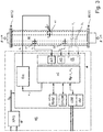
- the density measuring device comprises a measuring transducer MW of the vibration type which can be connected or connected via an inlet end # 111 and an outlet end # 112 to the process line, for example designed as a pipeline, which transducer in operation corresponds to the medium to be measured, such as a low-viscosity liquid and / or a highly viscous paste and / or a gas is flowed through.
- the transducer MW generally serves to generate mechanical reaction forces in the medium flowing through, namely in particular inertia forces dependent on the density, but possibly also Coriolis forces dependent on a mass flow rate and / or friction forces dependent on a viscosity, which can be detected by sensors, thus have a measurable effect on the transducer.
- the density ⁇ and possibly also the mass flow rate m and / or the viscosity ⁇ of the medium can be measured.
- the transducer MW is also set up to generate at least one primary signal which has at least one characteristic signal parameter dependent on the density, in particular a signal frequency dependent on the density and / or a signal amplitude dependent on the density and / or one dependent on the density Phase angle.
- the density measuring device comprises a measuring device electronics ME, which is electrically connected to the measuring transducer MW, especially during operation from an external connection cable and / or by means of an internal energy storage device, for generating measured values (X ⁇ ) or measuring values representing the density.
- the measuring device electronics ME formed, for example, by means of at least one microprocessor and / or by means of a digital signal processor (DSP) can, as in FIG Fig. 1 indicated, for example in a single, possibly also chambered, electronics housing 200 of the density measuring device.
- Said electronics housing 200 can, depending on the requirements placed on the density measuring device, also be designed, for example, to be impact-resistant and / or also to be explosion-proof and / or hermetically sealed.
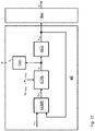
- the measuring device electronics ME as in Fig. 3 shown schematically in the manner of a block diagram, a driver circuit Exc serving to control the transducer and a measurement and evaluation circuit ⁇ C which processes primary signals from the transducer MW, for example formed by means of a microprocessor and / or communicating with the driver circuit Exc during operation which generates measured values representing at least the density, but possibly also the instantaneous or a totalized mass flow rate and / or the viscosity, during operation.
- the measuring device electronics can also be designed in such a way that, with regard to the circuit structure, it uses one of the measuring device electronics known from the prior art mentioned at the beginning, for example US-B 63 11 136, or, for example, also a measuring transducer on the part of the applicant , e.g. under the designation "PROMASS 83F" or at http://www.de.endress.com/#product/83F, corresponds to the Coriolis mass flow / density measuring device offered.
- the measured values generated by means of the measuring device electronics ME can also be displayed, for example, on site, namely directly at the measuring point formed by means of the density measuring device.
- the density meter can be on site, as well Fig.
- a display and operating element HMI that communicates with the measuring device electronics, possibly also portable, such as an LCD, OLED or TFT display placed in the electronics housing 200 behind a window provided therein, as well as a corresponding input keyboard and / or a touch screen.
- the measuring device electronics ME which can also be (re) programmed or remotely parameterized, for example, can advantageously be designed in such a way that, when the density measuring device is in operation, it can be operated with an electronic data processing system superordinate to it, for example a programmable logic controller (PLC), a personal computer and / or a workstation, via a data transmission system, for example a field bus system such as FOUNDATION FIELDBUS, PROFIBUS, and / or wirelessly by radio, can exchange measurement and / or other operating data, such as current measured values, system diagnostic values, system status messages or else Setting values used to control the density measuring device.
- PLC programmable logic controller
- PROFIBUS PROFIBUS
- FIG. 3 Shown embodiment shown, in particular the measuring and evaluation circuit ⁇ C by means of a microcomputer provided in the measuring device electronics ME, for example realized by means of a microprocessor or a digital signal processor (DSP), and by means of program programs implemented accordingly and running therein. Codes be implemented.
- the program codes as well as other operating parameters useful for controlling the density measuring device, such as setpoints for controllers or controller algorithms implemented by means of the measuring device electronics can, for example, be persistently stored in a non-volatile data memory EEPROM of the measuring device electronics ME when starting the same into a, for example, integrated in the microcomputer, volatile data memory RAM are loaded.
- Microprocessors suitable for such applications are, for example, those of the TMS320VC33 type, as offered on the market by Texas Instruments Inc.
- the measuring device electronics ME can be designed in such a way that it can be fed from an external energy supply, for example also via the aforementioned field bus system.
- the measuring device electronics ME can, for example, have such an internal energy supply circuit NRG for providing internal supply voltages U N , which during operation is fed by an external energy supply provided in the aforementioned data processing system via the aforementioned fieldbus system.
- the density measuring device can for example be designed as a so-called four-wire device, in which the internal power supply circuit of the measuring device electronics ME by means of a first pair of lines with an external power supply and the internal communication circuit of the measuring device electronics ME by means of a second pair of lines with an external data processing circuit or to an external data transmission system.
- the measuring device electronics can, however, also be designed in such a way that, as also mentioned in the introduction, among other things US-B 72 00 503 , the US-B 77 92 646 shown, can be electrically connected to the external electronic data processing system by means of a two-wire connection configured, for example, as a 4-20 mA current loop and is supplied with electrical energy via it, as well as measured values for the data processing system can transfer.
- the measuring device electronics ME which can also be (re) programmed on site and / or via the communication system, can be connected to the one corresponding - for example, one of the relevant industrial standards, such as IEC 61158 / IEC 61784, compliant - have communication interface COM for data communication, e.g. for sending measurement and / or operating data, including the measured values representing the density and possibly also the the measured values representing viscosity, mass flow or mass flow rate, to the already mentioned programmable logic controller (PLC) or a higher-level process control system and / or to receive setting data for the density measuring device.
- PLC programmable logic controller
- connection lines which are routed from the electronics housing 200, for example via cable bushings, into a transducer housing 100 of the transducer and are laid at least in sections within the same transducer housing 200.
- the connection lines can be designed at least partially as electrical, at least in sections in electrical insulation-sheathed line wires, for example in the form of "twisted-pair" lines, ribbon cables and / or coaxial cables.
- the connection lines can also be formed, at least in sections, by means of conductor tracks of a, for example, flexible, optionally also lacquered printed circuit board, cf. also those mentioned at the beginning US-B 67 11 958 or US-A 53 49 872 .
- the measuring transducer comprises an inner part which is arranged in a measuring transducer housing 100 and which actually effects the physical-electrical conversion of the density and possibly also the viscosity or the mass flow rate.
- a measuring transducer housing 100 that hermetically seals the interior of the transducer MW from the surrounding atmosphere, and possibly also serves as a pressure- and / or explosion-proof protective cover, can for example consist of a - smooth or corrugated - stainless steel sheet or also a Be made of plastic.
- the transducer housing 100 as also in FIG Fig.
- a hermetically sealed and / or pressure-tight bushing, for example produced by means of glass and / or plastic potting, for electrical connection lines laid between the measuring device electronics and the measuring transducer can furthermore be arranged inside the connecting piece.
- the inner part, and consequently the measuring transducer MW formed therewith basically comprises at least one - im in the Fig. 4 and 5
- the exemplary embodiment shown is namely a single measuring tube 10, which is curved at least in sections, with a lumen surrounded by a tube wall.
- the tube wall of the at least one measuring tube can for example consist of a metal, for example titanium or a titanium alloy, tantalum or a tantalum alloy, zirconium or a zirconium alloy, a stainless steel or a nickel-based alloy, or, for example, also of silicon.
- the at least one measuring tube 10 extends, as from the Fig.
- the at least one measuring tube 10 can be shaped in such a way that the aforementioned center line, as is quite common with measuring transducers of the type in question, lies in an imaginary tube plane of the measuring transducer.
- the useful vibrations of the at least one measuring tube 10 are designed so that the at least one measuring tube 10 is made to vibrate during operation in such a way that the same measuring tube 10 executes oscillatory movements over the entire oscillation length about an imaginary oscillation axis that leads to one of the two measuring tube ends 11 #, 12 # imaginary connecting imaginary connecting axis is parallel or coincident.
- the useful vibrations can, for example, correspond to a vibration form of a natural bending vibration mode, for example a bending vibration fundamental mode, of the at least measuring tube, and thus be bending vibrations about the same vibration axis.
- the at least one measuring tube 10 can also advantageously be shaped and arranged in the measuring transducer in such a way that the aforementioned connecting axis essentially runs parallel to an imaginary longitudinal axis L of the measuring transducer connecting the inlet and outlet end of the measuring transducer, possibly also with the same Longitudinal axis L coincides.
- the transducer MW is intended to be used for a large number of different applications, especially in the field of industrial measurement and automation technology, it is also provided that the at least one measuring tube has a caliber (inner diameter) that is greater than 1 mm, especially greater than 10 mm, sometimes even more than 80 mm.
- MEMS microsystem technology
- the caliber of the at least one measuring tube as also mentioned in the above-mentioned US-B 64 77 901 , US-B 66 47 778 or. US-B 70 59 176 mentioned, but also smaller than 1 mm, especially also smaller than 0.5 mm, selected.
- the inner part of the transducer can also have a mechanical measuring tube with the (single) - here curved - measuring tube 10 coupled, for example also similar to the measuring tube 10 U- or V-shaped, counter-oscillator 20 to minimize disturbing influences acting on the inner part as well as to reduce the total vibration energy emitted by the respective transducer to the connected process line.
- the counter-oscillator 20 is laterally spaced from the measuring tube 10 and is fixed on the inlet side to form a first coupling zone defining the aforementioned first measuring tube end 11 # and forming a second coupling zone defining the aforementioned second measuring tube end 12 # on the outlet side.
- the counter-oscillator 20 - running essentially parallel to the measuring tube 10 here - is advantageously produced from a metal, such as steel, titanium or zirconium, which is compatible with the measuring tube 10 in terms of thermal expansion behavior. As in Fig.
- the counter-oscillator 20 can, for example, by means of plates arranged on the left and right of the measuring tube 10 or also on the left and right of the Measuring tube 10 arranged (dummy) tubes be formed.
- the counter-oscillator 20 - such as, for example, in that mentioned US-B 66 66 098 proposed - also be formed by means of a single (dummy) tube running parallel to the side of the measuring tube.
- the counter-oscillator 20 in the exemplary embodiment shown here is held by means of at least one inlet-side first coupler 31 on the first measuring tube end 11 # and by means of at least one outlet-side second coupler 32, in particular essentially identical to the coupler 31, on the second measuring tube end 12 #.
- simple junction plates can serve as couplers 31, 32, which are fastened to the measuring tube 10 and counter-oscillator 20 in a corresponding manner on the inlet side and outlet side, respectively.
- a completely closed box or possibly also partially open frame is used as a coupler 31 or as a coupler 32, by means of node plates spaced apart from one another in the direction of the imaginary longitudinal axis L of the transducer together with protruding ends of the counter-oscillator 20 on the inlet side and outlet side.
- the measuring tube 10 can also be seen via a straight first connecting pipe section 11 that opens out on the inlet side in the area of the first coupling zone and via a straight second connecting pipe section 12 that opens out on the outlet side in the area of the second coupling zone, in particular essentially identical to the first connecting pipe section 11 correspondingly connected to the process line supplying or discharging the medium, an inlet end of the inlet-side connecting pipe section 11 practically forming the inlet end of the measuring transducer and an outlet end of the outlet-side connecting pipe section 12 forming the outlet end of the measuring transducer.
- the measuring tube 10 and together with the two connecting tube pieces 11, 12 can be made in one piece, so that for their production, for example, a single tubular semi-finished product made of a material customary for such transducers, such as stainless steel, titanium, zirconium, tantalum or corresponding alloys of it, can serve.
- a single tubular semi-finished product made of a material customary for such transducers, such as stainless steel, titanium, zirconium, tantalum or corresponding alloys of it, can serve.
- a single tubular semi-finished product made of a material customary for such transducers, such as stainless steel, titanium, zirconium, tantalum or corresponding alloys of it, can serve.
- a single tubular semi-finished product made of a material customary for such transducers, such as stainless steel, titanium, zirconium, tantalum or corresponding alloys of it, can serve.
- the two connecting pipe pieces 11, 12 are aligned with one another and with an imaginary longitudinal axis L of
- the two connecting pipe pieces 11, 12 are aligned with one another in such a way that they run essentially parallel to the imaginary longitudinal axis L or to the aforementioned imaginary oscillation axis or that the connecting pipe pieces 11, 12 both to the longitudinal axis L as well as to each other essentially cursing. Since the two connecting pipe pieces 11, 12 in the exemplary embodiment shown here are essentially straight over their entire length, they are accordingly aligned with each other and with the imaginary longitudinal axis L as a whole.
- the transducer housing 100 is fixed, especially rigid, to an inlet end of the inlet-side connecting pipe section 11 which is distal with respect to the first coupling zone and to an outlet end of the outlet-side connecting pipe section 12 which is distal with respect to the second coupling zone , in such a way that the entire inner part - formed here by means of measuring tube 10 and counter-oscillator 20 - is not only completely encased by the transducer housing 100, but is also held in the transducer housing 100 so that it can vibrate due to its own weight and the spring action of the two connecting pipe sections 11, 12.
- a first connection flange 13 for connection to a medium of the process line feeding the measuring transducer is on the inlet side of the measuring transducer and a second connection flange 14 on the outlet side intended for a line segment of the process line leading away from the measuring transducer.
- the connection flanges 13, 14 can, as is quite common in the case of measuring transducers of the type described, also integrated into the measuring transducer housing 100 at the end, namely designed as an integral part of the measuring transducer housing.
- first connection flange 13 can be molded onto the inlet-side connecting pipe section 11 at its inlet end and the second connection flange 14 can be molded onto the outlet-side connecting pipe section 12 at its outlet end by means of a corresponding soldered or welded connection.
- the measuring device electronics ME comprise a driver circuit Exc and the measuring transducer MW at least one electrically connected to the driver circuit Exc , electromechanical vibration exciter 41.
- the at least one - here the only one acting on the at least one measuring tube 10 - vibration exciter 41 can be placed, for example, in such a way that, as in FIG Fig. 4 and 5 indicated and, as is quite common with transducers of the type in question, acts in the middle of the measuring tube, namely formed in the region of half an oscillation length, on the at least measuring tube 10.
- the at least one measuring tube 10 is actively stimulated during operation by means of the at least one vibration exciter 41, at least temporarily, to useful vibrations that are predominantly or exclusively designed as flexural vibrations around the imaginary vibration axis mentioned.
- the at least one measuring tube 10 is excited by means of the vibration exciter 41 to such flexural vibrations in which the at least one measuring tube 10 oscillating around the same axis of oscillation - for example in the manner of a cantilever clamped on one side - at least partially bends according to an oscillation shape of a natural bending oscillation fundamental mode, such that the bending oscillations, and therefore the useful oscillations of the measuring tube, only have an inlet-side vibration node in the area of the inlet-side coupling zone defining the inlet-side measuring tube end 11 # and an outlet-side oscillation zone defining the outlet-side measuring tube end 12 # exhibit.
- the vibration exciter 41 is designed as an electrodynamic vibration exciter, namely constructed in the manner of a voice coil, in such a way that the vibration exciter 41 has a cylindrical excitation coil, which is electrically connected to the driver circuit Exc, and therefore to the measuring device electronics ME formed therewith has a permanent magnetic armature, therefore a magnetic field, and that the same magnetic field interacts with an (alternating) magnetic field generated by means of the excitation signal in the excitation coil in a manner causing relative movements of armature and excitation coil.
- the excitation coil can be fixed to the counter-oscillator 20 and the armature from the outside to the measuring tube 10, for example.
- the vibration exciter 41 can, for example, also be an electrostatic one, namely by means of a capacitor, of which a first capacitor plate on the measuring tube and a second capacitor plate on the counter-oscillator or - not least in the case of measuring transducers formed by means of a measuring tube with a very small caliber of less than 1 mm Can usually be fixed on the respective transducer housing, formed vibration exciter or designed as a piezoelectric vibration exciter.
- the actively excited useful vibrations are bending vibrations of the measuring tube
- these can be used in the case of the in Fig. 4 and 5
- a measuring transducer formed by means of measuring tube 10 and counter-oscillator 20 it can advantageously be designed in such a way that measuring tube 10 executes oscillatory movements that periodically change a relative distance between measuring tube 10 and counter-oscillator 20 with a useful frequency f N.
- the counter-oscillator 20 can also be excited to simultaneous cantilever oscillations, for example in such a way that it has oscillations at the same frequency as the useful oscillations, for example flexural oscillations around a virtual axis of oscillation parallel to the mentioned longitudinal axis L, which are at least partially, in particular in the area of the point of application formed by means of the vibration exciter 41, and / or at least temporarily, namely when the measuring tube is not flowed through, essentially in phase opposition to the measuring tube 10.
- the oscillations of the counter oscillator 20 can be designed in such a way that they are of the same modal order as the useful oscillations. In other words, the measuring tube 10 and the counter-oscillator 20 can then move in the manner of tuning fork prongs oscillating against one another.
- the driver circuit Exc and therefore the measuring device electronics of the density measuring device according to the invention, is also set up to generate an (analog) electrical excitation signal e 1 and to feed electrical power E exc into the vibration exciter 41 by means of the same excitation signal e 1.
- the excitation signal e 1 can, as is quite common in density measuring devices of the type in question, be an at least temporarily harmonic electrical alternating signal with an impressed alternating voltage and / or an impressed alternating current.
- a digital phase locked loop PLL
- a current intensity of the excitation signal which determines an amount of the same excitation forces, for example by means of a corresponding, possibly digital current regulator the driver circuit can be set appropriately.
- the excitation signal e 1 can also be generated, for example, based on a digital control signal e 1D initially generated by the measurement and evaluation circuit ⁇ C, by means of which, during operation, a power amplifier that is contained in the driver circuit Exc and ultimately provides the excitation signal e 1 is controlled.
- the digital control signal e 1D can, for example, be a digital signal generated by means of a numerically controlled oscillator (NCO), for example also sinusoidal.
- NCO numerically controlled oscillator
- the measuring device electronics ME can, for example, also be designed to regulate the excitation signal in such a way that the useful vibrations have a constant amplitude that is largely independent of the density ⁇ or the viscosity ⁇ of the respective medium to be measured.
- the vibration exciter 41 in turn serves or is set up to use the same excitation signal e1 to feed electrical power E exc into a (force) point of application formed by means of the vibration exciter 41 on the at least one measuring tube and deflecting or deflecting it in the manner described above.
- the (naturally vectorial) driving force F for the purpose of a targeted excitation of the useful vibrations is designed so that it is a useful force component F introduced into the at least one measuring tube 10 N , namely a periodic force component which changes with an excitation frequency corresponding to the useful frequency f N and ultimately causes the useful vibrations.
- driver circuits suitable for the density measuring device suitable for the density measuring device according to the invention
- their driver circuit is, for example, also designed in such a way that the respective useful vibrations are regulated to a constant amplitude, that is to say also largely independent of the density ⁇ or the viscosity ⁇ .
- the measuring transducer further comprises an additional pair of connecting wires to the measuring device electronics, for example by means of an additional pair of connecting wires, also not shown here for reasons of clarity ME electrically connected first oscillation sensor 51.
- the oscillation sensor 51 is set up here to detect oscillation movements of the at least one measuring tube - not least oscillating movements corresponding to the useful oscillations or movements of oscillations of the measuring tube with useful frequency f N - and converting them into a representing, as a To convert the primary signal of the transducer serving first vibration measurement signal s 1 , for example with a voltage corresponding to a speed of the recorded vibration movements or a voltage corresponding to the recorded vibration movements ondating current. Due to the fact that the at least one measuring tube 10 carries out the mentioned useful vibrations, i.e.
- the vibration measurement signal s 1 generated by the vibration sensor 51 has a signal frequency corresponding to the useful frequency or contains the vibration measurement signal s 1 - for example in the case of a broadband and / or multimodal vibration excitation by disturbances introduced from the outside via the connected pipeline and / or via the medium flowing through - at least one corresponding useful signal component, namely a periodic signal component with a the signal frequency corresponding to the useful frequency f N.
- the vibration sensor 51 can, for example, be designed as an electrodynamic vibration sensor, namely constructed in the manner of a plunger coil, so that the vibration sensor 51 is electrically connected to a counter-vibrator 20 and at the same time to the measuring and evaluation circuit, i.e.
- the vibration sensor 51 can, for example, also be designed as a capacitive vibration sensor formed by means of a capacitor, of which a first capacitor plate can be fixed to the measuring tube and a second capacitor plate to the counter-oscillator.
- the vibration sensor 51 is arranged at a distance from the vibration exciter 41 along the at least measuring tube, for example in this way that so that the inlet-side vibratory movements of the measuring tube, namely - as in Fig. 3 Schematically shown - Vibration movements of the at least one measuring tube 10 at a measuring point located between the measuring tube end # 11 and the vibration exciter 51, although they can be detected from both the measuring tube end # 11 and the vibration exciter 51.
- the vibration measurement signal s 1 generated by means of the vibration sensor 51 is, as also in FIG Fig. 3 shown, the measuring device electronics ME and initially fed to an input circuit FE, which is used to first suitably preprocess the vibration measurement signal s 1 , namely to prepare it for a digital signal processing on which the actual density measurement is based, for example to pre-amplify, filter and digitize it .
- the input circuit FE as well as the measuring and evaluation circuit ⁇ C can also be used in conventional density or Coriolis mass flow / density measuring devices for the purpose of converting primary signals supplied by means of a transducer of the vibration type or for the purpose of determining the density, possibly also from
- the measured values representing the mass flow rate and / or the viscosity that have already been used and established circuit technologies can be used, for example also those according to the prior art mentioned at the beginning.
- the measurement and evaluation circuit ⁇ C as also in the one mentioned above US-B 63 11 136 shown or the aforementioned transducers of the measuring device series "PROMASS 83F" are realized, Formed by means of at least one microprocessor, and therefore provided for processing digital signals, the measuring device electronics are also set up to convert the vibration signal s 1 into a corresponding digital vibration measurement signal s 1D by means of an analog-to-digital converter A / D and then to process or evaluate digitally.
- the measuring device electronics of the density measuring device according to the invention are set up in particular to use the vibration measurement signal s 1 , for example also a digital vibration measurement signal s 1D obtained therefrom, to present the density of the medium carried in the transducer Generate density measurement value X ⁇ or update it repeatedly.
- the measuring and evaluation circuit, and therefore the measuring device electronics ME of the density measuring device according to the invention is also set up, inter alia, to determine a frequency measurement value X f representing the useful frequency f N or to update it repeatedly during operation, for example using the excitation signal e 1 and / or the at least one vibration measurement signal s 1 , as well as the same frequency measurement value X f when determining the density measurement value X ⁇ or the density measurement values.
- the measuring device-specific coefficients A and B listed in the same calculation rule can in turn, in the manner known per se to the person skilled in the art, by measuring the density measuring device using different media, for example also in each case kept at a temperature corresponding to the mentioned reference temperature, with different densities, for example Air or water and / or glycerine, are determined in advance, for example in the course of a wet calibration carried out in the manufacturer's works.
- the useful vibrations of the at least one measuring tube 10 excited to determine the density are, due to its natural vibration properties, designed such that - as in FIG Fig. 6 or 7 by means of a so-called pointer model or also a pointer diagram illustrates a speed response V N of the at least one measuring tube 10, namely a speed of the oscillatory movements of the at least one measuring tube 10 at the point of application, which changes over time with the useful frequency f N , compared to the useful force component F N of the driving force is phase shifted by a certain phase shift angle ⁇ N , which is dependent on the actually set excitation frequency, and therefore on the actually set useful frequency f N.
- the aforementioned dependence of the speed response V N on the useful force component F N is such that in the event that the set excitation frequency - as is usual with conventional density measuring devices of the type in question - corresponds to an instantaneous resonance frequency of the at least one measuring tube 10, i.e. a resonance condition ( ) is fulfilled, namely the phase shift angle ⁇ N is approximately zero ( Fig.
- the phase shift angle ⁇ N is less than 0 °, for example about -50 ° to -70 ° ( Fig. 7 ).
- the excitation or the useful frequency can be approximately between 490.05 Hz and 490.5 Hz at a phase shift angle ⁇ N of between -50 ° and -70 °.
- the driving force F again or their Nutzkraftkomponente F N can in regard to the expert known per se, for example by means of an appropriately conditioned current intensity or voltage level of the electrical excitation signal e1 with respect to their amplitude and same by adjusting a signal frequency of the excitation signal e 1 of their Excitation frequency can be precisely adjusted. Accordingly, according to a further embodiment of the invention, the measuring device electronics are set up so that the driving force F i is not finally to adjust their useful force component F N by changing a signal frequency of the excitation signal e 1.
- the same control signal e 1D - possibly taking into account an actual transmission behavior of the driver circuit Exc and / or the at least vibration exciter 41 - with regard to both the frequency and also the amplitude can already be adjusted appropriately to the desired useful force component by means of the measurement and evaluation circuit ⁇ C.
- a characteristic of the useful frequency f N used in each case for measuring the density ⁇ in density measuring devices of the type in question is that it is usually an oscillation frequency at which the phase shift angle ⁇ N between the speed response V N and the useful force component F.
- N of the driving force F is set to a correspondingly predetermined phase setpoint value, or vice versa, which results after the phase shift angle ⁇ N , for example by continuously or quasi-continuous or step-by-step change of the excitation frequency by means of the measuring device electronics at least for one predetermined phase control interval, namely required for the actual measurement of the useful frequency, has been steadily adjusted to the respective phase setpoint value.
- conventional density measuring devices typically use resonance vibrations, i.e. those vibrations as useful vibrations in which the phase shift angle ⁇ N is at least approximately 0 ° or, ideally, is exactly zero, in which the aforementioned resonance condition ( ) is fulfilled (cf. Fig. 6 ).
- the actual duration of the respectively required phase control interval is not least due to a dynamic, namely a temporal behavior of the means of the vibration exciter, the at least one measuring tube, the at least one vibration sensor and the measuring device electronics, in particular the measuring and evaluation circuit and the driver circuit , overall formed mechatronic system on the one hand, as well as a processing speed or update rate with which the measuring and evaluation circuit can determine the useful frequency based on the vibration signal and generate the corresponding frequency measured values.
- the update rates for the frequency measured values have so far typically been in the range from approximately 100 Hz to approximately 200 Hz.
- the measuring device electronics ME of the density measuring device are also set up to adjust the driving force required for the active excitation of the useful vibrations by means of the vibration measurement signal s 1 and the excitation signal e 1, in such a way that during a predetermined phase control interval ⁇ t ⁇ , for example 10 ms or longer, the same phase shift angle ⁇ N is set to a predetermined phase setpoint ⁇ N_SOLL .
- An actual required duration of the phase control interval ⁇ t ⁇ - which is of course repeatedly passed through by the measuring device electronics during operation - depends on the one hand on the speed at which the usable frequency can be adjusted to a time-changing density during operation and on the other hand, among other things, according to how many oscillation periods of the useful oscillations are actually recorded for a single frequency measurement value or how many oscillation periods of the oscillation measurement signal are actually to be evaluated.
- the measuring device electronics are also set up to regulate the phase shift angle ⁇ N to a predetermined phase setpoint ⁇ N_SOLL, namely to set it to a corresponding phase value or to keep it at a corresponding phase value, in such a way that the phase shift angle ⁇ N at constant density by less than ⁇ 1% of the same phase target value ⁇ N_SOLL and / or by less than ⁇ 2 ° around the same phase target value ⁇ N_SOLL fluctuates or ideally during the entire phase control interval and / or not at the moment varying density ⁇ is kept constant at that nominal phase value ⁇ N_SOLL , and is therefore stationary.
- the adjustment of the phase shift angle ⁇ N to the phase target value ⁇ N_SOLL can be done by changing a signal frequency of the excitation signal e1 until the phase shift angle ⁇ N has reached a predetermined phase target value ⁇ N_SOLL , for example in such a way that the measuring device -Electronics in the case of a phase shift angle ⁇ N that is set too low, namely smaller than the phase setpoint ⁇ N_SOLL, and in such a way that the measuring device electronics in the case of an excessively large, namely greater than the phase setpoint ⁇ N_SOLL set phase shift angle ⁇ N same signal frequency increased.
- a phase value for the currently actually set phase shift angle ⁇ N can in turn by means of the measurement and evaluation circuit ⁇ C, for example based on a determined between the vibration measurement signal s 1 and the excitation signal e 1 , in the measuring device electronics of density measuring devices in question standing type in operation regularly take place anyway existing phase angle.
- the phase setpoint ⁇ N_SOLL can, if necessary - for example for the purpose of measuring other measured variables, such as a viscosity ⁇ , of the medium carried in at least one measuring tube 10 - also be changeable, so that the measuring device electronics do the measuring the specified phase setpoint value ⁇ N_SOLL are temporarily replaced by another, for an additional device function that deviates from the measurement of the density, according to the specified phase setpoint value, so that the measuring device electronics afterwards adjusts the phase shift angle ⁇ N to the same phase setpoint.
- other measured variables such as a viscosity ⁇
- the useful vibrations - in contrast to conventional density measuring devices used up to now - are designed so that the phase shift angle ⁇ N for the purpose of measuring the useful frequency f N required to determine the density by means of the measuring device electronics is less than -30 ° and greater than -70 °, or vice versa, that the useful frequency f N is set by means of the measuring device electronics so that the same useful frequency f N is more than 1.00001 times, nevertheless less than 1.001 -fold of a resonance frequency f R of the at least one measuring tube, but also does not correspond to any other resonance frequency of the at least one measuring tube 10, so the determination of the density is based on useful vibrations for which the resonance condition ( ) namely is not fulfilled.
- phase shift angle ⁇ N or such a useful frequency f N having useful oscillations can namely - in Fig. 8 and FIG. 9 based on diagrams illustrating the dependence of the speed response V N on the selected excitation frequency (amplitude frequency response) or in Fig.
- phase frequency response that illustrates the dependence of the useful frequency f N on the selected phase shift angle ⁇ N - dependence of the excitation or useful frequency f N (corresponding to the phase shift angle ⁇ N to be set or set) also on a momentary viscosity ⁇ of the medium, resulting from a dependency of the phase shift angle ⁇ N (set according to the phase setpoint value) on an instantaneous damping counteracting the stimulated useful vibrations, can be almost eliminated, or at least reduced to a considerable extent.
- a diagram phase frequency response
- phase shift angle ⁇ N is particularly pronounced in the range of the resonance frequency f R , which is preferably used in conventional density measuring devices of the type in question for measuring the density, while the same dependence on smaller, namely negative, phase shift angles ⁇ N , therefore with excitation or useful frequencies f N lying in the frequency range slightly above the same resonance frequency f R decreases or is practically no longer measurable.
- the resonance frequency f R - a resonance frequency f R for that for density measuring instruments of the type in question - not least also used in conventional density measuring devices up to now for the determination of density as a useful frequency regularly striven for high measurement accuracy have a considerable dependence also on the damping of the useful vibrations or the viscosity ⁇ of the respective medium causing them.
- the measuring device electronics of the density measuring device are accordingly also set up to use the vibration measurement signal s 1 and the excitation signal e 1 to generate the driving force, in particular adjust the useful force component or its excitation frequency so that the phase shift angle ⁇ N , as in Fig.
- the useful frequency has a frequency value during the phase control interval ⁇ t ⁇ , which corresponds to more than 1.00001 times, nevertheless less than 1.001 times an instantaneous frequency value of a resonance frequency f R of the at least one measuring tube 10.
- the measuring device electronics are set up to determine the at least one frequency measurement value X f based on the vibration measurement signal s1 obtained during the phase control interval, such that the same frequency measurement value X f is the useful frequency for the phase control interval ⁇ t ⁇ , and to generate the density measurement value X ⁇ using the same frequency measurement value X f.
- a phase shift angle ⁇ N suitable for the respective transducer or the density measuring device formed therewith can be determined in advance, for example, by computer-aided simulation calculation and / or experimentally, for example by, as inter alia, also from the Fig. 10 apparent, for two or more reference media with differing viscosity, nevertheless at least approximately the same density, respectively associated frequency responses are determined and based on the same frequency responses - for example by determining an intersection of a number of frequency responses or a mean intersection formed by a number of such adjacent intersection points , a, im in Fig. 10
- the diagram shown is set at about -52 °, phase value with a minimal dependence on the viscosity as phase setpoint ⁇ N_SOLL .
- the measuring device electronics also set up to keep a signal frequency of the excitation signal e 1 during the entire phase control interval at a frequency value that is not less than 1,0001 times a resonance frequency f R of the at least a measuring tube, for example namely a lowest resonance frequency and / or a resonance frequency corresponding to a bending vibration fundamental mode, and is not more than 1.01 times the same resonance frequency.
- the setting of the frequency of the excitation signal, hence the useful frequency f N can, as is quite common with density measuring devices of the type in question, using a digital phase control loop provided in the measuring device electronics, for example implemented by means of the measuring and evaluation circuit ⁇ C (PLL) take place, which uses the aforementioned relationship between the instantaneous excitation or useful frequency f N and the instantaneous phase shift angle ⁇ N to adapt the control signal e 1D to the instantaneous vibration properties of the inner part formed by means of the at least one measuring tube 10.
- PLL measuring and evaluation circuit
- the phase shift angle ⁇ N can be adjusted to the phase setpoint ⁇ N_SOLL, for example, by the phase control loop changing a signal frequency of the excitation signal e1 until through the phase control loop based on the mentioned vibration measurement signal s 1 or using one obtained therefrom digital auxiliary signal, such as the aforementioned digital vibration measurement signal s 1D , a match between the phase shift angle ⁇ N and the specified phase target value ⁇ N_SOLL is detected or by the phase control loop not changing the same signal frequency of the excitation signal e1 if the phase shift angle ⁇ N with the phase setpoint ⁇ N_SOLL is determined.
- a digital phase control loop suitable for use in a density measuring device according to the invention for regulating the excitation frequency, hence the useful frequency f N can have a phase comparator COMP, by means of which a recurring comparison of an instantaneous phase position of the digital vibration measurement signal s 1D applied to a first input with an instantaneous phase position of the control signal e 1D fed back to a second input - here designed as a sinusoidal digital signal - and by means of which, based on the comparison, an error signal Err ⁇ is generated, which signals whether or to what extent the phase positions of the two inputs applied signals - here namely the digital vibration measurement signal s 1D and the digital control signal e 1D - differ from one another.
- the error signal Err ⁇ is then fed to a frequency controller CTRL, which is used to convert the error signal Err ⁇ , taking into account a phase control setpoint ⁇ N_SOLL preset for the frequency controller CTRL, for example permanently programmed, into a numerical control value that can be tapped at an output of the frequency controller CTRL a Represents the signal frequency with which the control signal e 1D is currently to be output.
- the phase control setpoint ⁇ N_SOLL corresponds to a numerical phase value that is determined in advance based on the phase setpoint ⁇ N_SOLL actually aimed for for the phase shift angle ⁇ N , and also taking into account any others by the density measuring device - for example, namely by the vibration exciter, the At least one vibration sensor and / or the measuring device electronics, in particular its measuring and evaluation circuit or its driver circuit, - caused influences on a phase shift between the excitation signal e 1 and the at least one vibration measurement signal s 1 .
- the structure and mode of operation of the vibration exciter must be taken into account when calculating the phase control setpoint ⁇ N_SOLL, not least in such a way that for the case mentioned, for example, that the vibration exciter 41 is designed in the manner of a voice coil, the useful excitation component of the excitation signal e 1 is at least approximately periodic current with the useful force component F N is at least approximately in phase with the same frequency, but has a periodic voltage which is identical in frequency to the useful force component F N , but is phase-shifted by an amount in the order of 90 °, or for the other case mentioned, that the vibration exciter comes from the electrostatic Type, namely formed by means of a capacitor, an electrical voltage of the excitation signal e 1 a periodic voltage component which is at least approximately identical in frequency and phase to the useful force component F N, nevertheless one to the useful force component component F N has the same frequency, but has a periodic current phase-shifted by an amount of the order of magnitude of 90 °.
- the structure and mode of operation of the at least one vibration sensor 51 must also be taken into account.
- the vibration measurement signal s 1 has a the speed response V N of the at least one measuring tube has a frequency and at least approximately in phase periodic voltage
- the vibration measurement signal s 1 for the other case mentioned, that the vibration sensor is formed by means of a capacitor has the same frequency as the speed response of the at least one measuring tube , nevertheless has periodic current phase-shifted by approximately + 90 ° with respect to the speed response.
- the signal transmission behavior specific to the measuring device electronics is also a resulting phase frequency response of the measuring device electronics in the calculation of the phase control setpoint ⁇ N_SOLL to be included accordingly or the measuring device electronics, not least the mentioned ones Input circuit, the measurement and evaluation circuit as well as the driver circuit, naturally inherent group delays associated with additional, namely delay-related phase shifts such as the aforementioned digital vibration measurement signal s 1D relative to the vibration measurement signal s 1 or also of the excitation signal e1 relative to the aforementioned digital control signal e 1D to be included accordingly in the phase control setpoint ⁇ N_SOLL.
- phase control setpoint ⁇ N_SOLL actually suitable for the density measuring device can, for example, be measured experimentally in the course of a calibration of the same density measuring device carried out in the manufacturer's plant and then stored in the mentioned non-volatile memory EEPROM of the measuring device electronics.
- the signal frequency representing control value output of the frequency controller CTRL is also transferred to an - here numerically controlled - oscillator NCO, which supplies the digital control signal e 1D sent to the driver circuit at an output with a signal frequency determined by the current control value.
- NCO numerically controlled - oscillator
- control value at the output of the frequency controller CTRL can also serve, for example, as a frequency measured value X f or to a calculation rule (3) that generates the density measured value X ⁇ , for example the above-mentioned calculation rule (3) for determining the density measured value X ⁇ executing and / or by means of a calculation routine executed by a microprocessor of the measuring device electronics, arithmetic unit CALC can be transferred.
- a phase-locked loop however, other frequency control circuits suitable for setting the useful frequency f N and known per se to the person skilled in the art can of course also be used, for example those that are based on positive feedback of the excitation signal e 1 to the at least one vibration measurement signal s 1 .
- the density measuring device can, if necessary and as is quite common with density measuring device of the type in question, furthermore a temperature sensor thermally coupled to at least one measuring tube 10, which - as in Fig.
- FIG Fig. 3 indicated - is set up to detect a temperature of the at least one measuring tube and convert it into a temperature measurement signal ⁇ 1 representing this, and / or a strain sensor mechanically coupled to at least one measuring tube, which - as in FIG Fig. 3 indicated - is set up to detect an expansion of the at least one measuring tube and to convert it into an expansion measurement signal ( ⁇ 1) representing it.
- the measuring device electronics can be set up to use the temperature measuring signal ⁇ 1 at least one temperature measured value X ⁇ , which represents a temperature of the at least one measuring tube, or by means of the strain measuring signal ⁇ 1, at least one expansion
- the measured value X ⁇ which represents an expansion of the at least one measuring tube or a mechanical stress built up within the at least one measuring tube as a result of the same expansion causing deformation of the transducer, and to determine the density measured value X ⁇ using the temperature Measurement value X ⁇ or the strain measurement value X ⁇ .
- the density measuring device uses the density measuring device according to the invention to determine the viscosity ⁇ of the medium carried in at least one measuring tube in addition to the density ⁇ , for example by using the measuring device -Electronics during the phase control interval based on the vibration measurement signal s 1 and / or the excitation signal determines at least one damping measurement value X D , which represents a damping that counteracts the useful vibrations of the at least one measuring tube, and - as, among other things, also in the input mentioned US-B 66 51 513 or US-B 60 06 609 proposed, based on the measured damping value X D, a measured viscosity value X ⁇ representing the viscosity ⁇ of the medium is generated.
- the viscosity ⁇ can also be determined by setting the slot frequency f N initially required for measuring the density ⁇ before and / or after the phase control interval, i.e. before or after the corresponding frequency Measured value X f has been determined, by means of the measuring device electronics, the excitation signal e 1 , and consequently the drive force F, are temporarily set so that the useful force component and the speed response now, as already mentioned or also in Fig. 6 shown the resonance condition ( ) meet, therefore the oscillation frequency of the so active excited vibrations correspond to the instantaneous resonance frequency f R.
- the measuring device electronics are set up to adjust the useful force component or its excitation frequency at least temporarily outside the phase control interval ⁇ t ⁇ , for example immediately before and / or immediately after it, in such a way that the phase shift angle ⁇ ⁇ N is not less than -5 ° and not more than + 5 °;
- the phase shift angle ⁇ ⁇ N during this time is not less than -2 ° and / or not more than + 2 °, namely that the excitation frequency of the useful force component, as is usual with conventional density measuring devices, is essentially one corresponds to the momentary resonance frequency of the at least one measuring tube, hence the useful vibrations of the at least one measuring tube outside the phase control interval ⁇ t ⁇ are temporarily resonance oscillations.
- the viscosity of the medium carried in the at least one measuring tube can be determined in the manner described above.
- the useful vibrations actively excited at the resonance frequency can also serve to target the measuring device electronics to the measuring point formed by means of the density measuring device in interaction with the connected pipeline and / or to adapt to any media changes made during operation, for example in such a way that the mentioned phase control setpoint ⁇ N_SOLL is appropriately fine-tuned, and / or to check the integrity or functionality of the density measuring device in the course of a recurring self-test, for example in such a way that one can use the Measuring device electronics diagnosed a significant deviation of one or more resonance frequencies from the preset values specified for them leads to the triggering of a warning message signaling reduced functionality and / or reduced measurement accuracy.
- the useful vibrations excited at the resonance frequency can also be used to determine a starting value from which the adjustment of the phase shift angle ⁇ ⁇ N by the measuring device electronics can be started or from which after a control deviation that is temporarily too high, for example after an abrupt one If the resonance frequency of the measuring tube changes by more than 1 Hz, for example as a result of a medium change, or in the event of a temporarily significantly fluctuating density, for example as a result of inhomogeneities temporarily formed in the medium, such as gas bubbles or solid particles entrained in a liquid, the phase shift angle ⁇ ntendedN quickly increases again the phase setpoint ⁇ N_SOLL can be brought up.
- the at least one measuring tube i.e. the mass flow or the mass flow rate ⁇ is different from zero
- the at the same time vibrating in the manner described above namely useful vibrations with a different from the current resonance frequency
- Measuring tube 10 executing the useful frequency in the medium flowing through, in addition to the inertia or friction forces, also induces Coriolis forces.
- Antinodes A momentary expression of these so-called Coriolis oscillations, which are superimposed on the stimulated useful oscillations and have the same frequency, is, in particular. with regard to their amplitudes, in particular also dependent on the instantaneous mass flow rate.
- Coriolis vibrations additionally evaluated for the purpose of measuring the mass flow rate in the case of a curved measuring tube, for example, torsional vibrations around a center line of the at least one measuring tube 10 in the range of half the center line of the at least one measuring tube 10, which are then performed in addition to the bending vibrations serving as useful vibrations, can be used Oscillation length imaginatively intersecting imaginary torsional oscillation axis are used.
- the measuring transducer also has a second vibration sensor 52, for example identical to the first vibration sensor 51, which is used to detect vibration movements of the at least one measuring tube and convert it to a second nevertheless to convert a vibration measurement signal s2 having a signal frequency corresponding to the useful frequency.
- the vibration sensor 52 like the vibration sensor 51, can be configured, for example, as an electrodynamic vibration sensor or, for example, also as a capacitive vibration sensor.
- the vibration sensors 51, 52 can also advantageously be designed and placed in the transducer in such a way that each of the vibration sensors predominantly vibrates the measuring tube 10 relative to the counter-oscillator 20, for example differentially, detected that both the oscillation measurement signal s 1 and the oscillation measurement signal s 2 represent oscillation movements of the at least one measuring tube 10 relative to the counter-oscillator 20.
- vibration sensor 52 is, as is customary with measuring transducers used in Coriolis mass flow / density measuring devices, arranged along measuring tube 10, thus at a distance from vibration sensor 51 as seen in the direction of flow on measuring tube 10, for example in such a way that, as shown in FIG Fig. 3 , 4th or 5 or their synopsis can be seen, the vibration sensor 51 is arranged on the inlet side and the vibration sensor 52 is arranged on the outlet side, and is therefore set up to detect vibration movements on the inlet side and outlet side, respectively.
- each of the vibration sensors 51, 52 is also, as is quite common with transducers of the type in question, equally spaced from the center of the at least one measuring tube 10 or from the single vibration exciter 41, which is placed here at half the vibration length.
- the measuring device electronics can be used to determine the mass flow rate in addition to the density of the medium that has flowed through the measuring tube during the phase control interval.
- the measuring device electronics are therefore also set up to additionally add a phase difference measured value X ⁇ based on both the first vibration measurement signal s1 and the second vibration measurement signal s2 during the phase control interval ⁇ t ⁇ determine which represents the phase difference ⁇ m dependent on the mass flow rate ⁇ for the phase control interval ⁇ t ⁇ ; this in particular, in order to subsequently generate a mass flow measured value X m representing the mass flow rate or the mass flow based on the phase difference measured value X ⁇ .
- the measuring device electronics are also set up to supply the useful force component F N or the phase shift angle also by means of the second vibration measurement signal s2, in particular based on both the vibration measurement signal s1 and the vibration measurement signal s2 adjust, for example in such a way that, by means of the vibration measurement signal s1 and the vibration measurement signal s2, initially a sensor sum signal representing the vibration movements of the measuring tube 10 at the location of the vibration exciter or the point of attack formed therewith or at least in phase with it, especially digital, is formed and then afterwards The same sum signal is supplied as a digital vibration measurement signal s 1D to the first input of the phase comparator COMP of the phase-locked loop (PLL) mentioned, and is therefore used to control the same phase-locked loop.
- the frequency measured value X f can also be determined using the vibration signal s2, for example also based on both the vibration measurement signal s1 and the vibration measurement signal s2.
- transducer is in the Fig. 4 and 5 representative embodiment shown only a single has curved measuring tube and at least insofar in its mechanical structure as well as its operating principle that in the aforementioned US-B 73 60 451 or.
- US-B 66 66 098 proposed or also resembles the transducers offered by the applicant under the type designation "PROMASS H", "PROMASS P" or “PROMASS S " - other transducers of the type in question can of course also be used to implement the invention, not least those with a straight and / or more than one measuring tube, roughly comparable to those mentioned in the introduction US-A 60 06 609 , US-B 65 13 393 , US-B 70 17 424 , US-B 68 40 109 , US-B 69 20 798 , US-A 57 96 011 or.
- the transducer can also have a single straight measuring tube or at least two, for example by means of an inlet-side flow splitter and an outlet-side flow splitter, if necessary also by means of at least one inlet-side coupling element and at least one outlet-side coupling element, mechanically coupled and / or structurally identical and / or have curved and / or parallel measuring tubes for guiding the medium to be measured, which vibrate at least intermittently during operation to generate the primary signals, approximately at the same frequency at a common oscillation frequency, but in antiphase, or the transducer can, for example, also use four straight lines or four be formed curved measuring tubes.
Landscapes
- Physics & Mathematics (AREA)
- General Physics & Mathematics (AREA)
- Health & Medical Sciences (AREA)
- Life Sciences & Earth Sciences (AREA)
- Chemical & Material Sciences (AREA)
- Analytical Chemistry (AREA)
- Biochemistry (AREA)
- General Health & Medical Sciences (AREA)
- Immunology (AREA)
- Pathology (AREA)
- Fluid Mechanics (AREA)
- Measuring Volume Flow (AREA)
Applications Claiming Priority (2)
| Application Number | Priority Date | Filing Date | Title |
|---|---|---|---|
| DE102013113689.3A DE102013113689B4 (de) | 2013-12-09 | 2013-12-09 | Dichte-Meßgerät |
| PCT/EP2014/073520 WO2015086224A1 (de) | 2013-12-09 | 2014-11-03 | DICHTE-MEßGERÄT |
Publications (2)
| Publication Number | Publication Date |
|---|---|
| EP3080560A1 EP3080560A1 (de) | 2016-10-19 |
| EP3080560B1 true EP3080560B1 (de) | 2021-07-14 |
Family
ID=51846651
Family Applications (1)
| Application Number | Title | Priority Date | Filing Date |
|---|---|---|---|
| EP14793095.2A Active EP3080560B1 (de) | 2013-12-09 | 2014-11-03 | Dichte-messgerät |
Country Status (5)
| Country | Link |
|---|---|
| US (1) | US10598534B2 (zh) |
| EP (1) | EP3080560B1 (zh) |
| CN (1) | CN105899917B (zh) |
| DE (1) | DE102013113689B4 (zh) |
| WO (1) | WO2015086224A1 (zh) |
Families Citing this family (20)
| Publication number | Priority date | Publication date | Assignee | Title |
|---|---|---|---|---|
| DE102015115499B4 (de) * | 2015-09-15 | 2023-11-02 | Endress+Hauser Flowtec Ag | Verfahren und Messvorrichtung zum Bestimmen der Kompressibilität eines strömenden Fluids |
| NL2016092B1 (en) * | 2016-01-14 | 2017-07-24 | Berkin Bv | Coriolis flowsensor. |
| DE102016114860A1 (de) * | 2016-08-10 | 2018-02-15 | Endress + Hauser Flowtec Ag | Treiberschaltung sowie damit gebildete Umformer-Elektronik bzw. damit gebildetes Meßsystem |
| DE102017102449A1 (de) * | 2017-02-08 | 2018-08-09 | Krohne Ag | Verfahren zur Druckmessung bei einem Coriolis-Massedurchflussmessgerät und Coriolis-Massedurchflussmessgerät |
| CN110709678B (zh) * | 2017-06-14 | 2021-09-07 | 高准公司 | 最小化振动仪表中的多音调驱动信号中的波峰 |
| DE102017127266A1 (de) * | 2017-11-20 | 2019-05-23 | Endress+Hauser Flowtec Ag | Verfahren zum Signalisieren einer Standardfrequenz eines Dichtemessers, welcher mindestens ein schwingfähiges Messrohr zum Führen eines Mediums aufweist |
| DE102017131199A1 (de) * | 2017-12-22 | 2019-06-27 | Endress + Hauser Flowtec Ag | Coriolis-Massendurchfluß-Meßgerät |
| CN108469407B (zh) * | 2018-03-16 | 2021-01-12 | 中国石油大学(华东) | 一种检测表面洁净程度的装置及方法 |
| WO2020032946A1 (en) * | 2018-08-09 | 2020-02-13 | Micro Motion, Inc. | Explosion proof feed-through |
| DE102019106762A1 (de) * | 2018-12-21 | 2020-06-25 | Endress + Hauser Flowtec Ag | Verfahren zum Ermitteln eines physikalischen Parameters einer mit Gas beladenen Flüssigkeit |
| EP3899448B1 (de) * | 2018-12-21 | 2024-03-27 | Endress + Hauser Flowtec AG | Coriolis-massendurchfluss-messer mit magnetfelddetektor |
| DE102019003075A1 (de) * | 2019-04-30 | 2020-11-05 | Endress+Hauser Flowtec Ag | Messgerät zum Charakterisieren eines inhomogenen, fließfähigen Mediums |
| US20200393278A1 (en) | 2019-06-13 | 2020-12-17 | Heinrichs Messtechnik Gmbh | Device for Compensating Viscosity-Induced Measurement Errors, for Coriolis Flow Measurement |
| DE102019116872A1 (de) | 2019-06-24 | 2020-12-24 | Heinrichs Messtechnik Gmbh | Verfahren und Vorrichtung zur Ermittlung eines Strömungsparameters mittels eines Coriolis-Durchflussmessgerätes |
| DE102019117101A1 (de) * | 2019-06-25 | 2020-12-31 | Endress+Hauser Flowtec Ag | Verfahren zum Ermitteln eines physikalischen Parameters einer beladenen Flüssigkeit |
| RU198129U1 (ru) * | 2020-02-21 | 2020-06-19 | Николай Васильевич Сизов | Поточный прямотрубный плотнометр высокого давления |
| DE112021003296A5 (de) | 2020-06-18 | 2023-05-11 | Endress+Hauser Flowtec Ag | Vibronisches Meßsystem |
| DE102020131649A1 (de) | 2020-09-03 | 2022-03-03 | Endress + Hauser Flowtec Ag | Vibronisches Meßsystem |
| CN112255140B (zh) * | 2020-10-10 | 2023-07-25 | 柳州工学院 | 液体密度智能化检测仪 |
| DE102020127382A1 (de) | 2020-10-16 | 2022-04-21 | Endress+Hauser Flowtec Ag | Verfahren zum Überprüfen eines vibronischen Meßsystems |
Citations (1)
| Publication number | Priority date | Publication date | Assignee | Title |
|---|---|---|---|---|
| DE8712331U1 (de) * | 1986-09-26 | 1988-01-28 | Flowtec AG, Reinach, Basel | Corioliskraft-Massendurchflussmesser |
Family Cites Families (65)
| Publication number | Priority date | Publication date | Assignee | Title |
|---|---|---|---|---|
| DE102013101369B4 (de) | 2013-02-12 | 2021-02-18 | Endress + Hauser Flowtec Ag | Coriolis-Massendurchfluß-Meßgerät |
| US4491009A (en) | 1983-06-10 | 1985-01-01 | Micro Motion, Inc. | Electronic circuit for vibrating tube densimeter |
| US4524610A (en) | 1983-09-02 | 1985-06-25 | National Metal And Refining Company, Ltd. | In-line vibratory viscometer-densitometer |
| EP0185709A4 (en) | 1984-06-04 | 1987-11-02 | Exac Corp | APPARATUS FOR MEASURING THE DENSITY AND SPEED OF FLOW-MASS. |
| JPH0663958B2 (ja) | 1986-10-09 | 1994-08-22 | マイクロ モ−ション インコ−ポレ−テッド | コリオリ流量計により流体密度を測定する方法、装置 |
| JP2575203B2 (ja) | 1987-07-15 | 1997-01-22 | マイクロ・モーション・インコーポレーテッド | 非対称および粘性減衰の補償により精度を向上した質量流量計 |
| GB8829825D0 (en) | 1988-12-21 | 1989-02-15 | Schlumberger Ind Ltd | A combined output and drive circuit for a mass flow transducer |
| US4996871A (en) | 1989-06-02 | 1991-03-05 | Micro Motion, Inc. | Coriolis densimeter having substantially increased noise immunity |
| US5497665A (en) | 1991-02-05 | 1996-03-12 | Direct Measurement Corporation | Coriolis mass flow rate meter having adjustable pressure and density sensitivity |
| US5373745A (en) | 1991-02-05 | 1994-12-20 | Direct Measurement Corporation | Single path radial mode Coriolis mass flow rate meter |
| EP0518124B1 (de) | 1991-06-09 | 1995-09-06 | Krohne AG | Coriolis-Massendurchflussmessgerät |
| US5295084A (en) | 1991-10-08 | 1994-03-15 | Micromotion, Inc. | Vibrating tube densimeter |
| EP0547455B1 (de) | 1991-12-19 | 1996-09-18 | Krohne AG | Massendurchflussmessgerät |
| US5796011A (en) | 1993-07-20 | 1998-08-18 | Endress + Hauser Flowtech Ag | Coriolis-type mass flow sensor |
| JP2558091B2 (ja) | 1993-07-21 | 1996-11-27 | エンドレス ウント ハウザー フローテック アクチエンゲゼルシャフト | コリオリ式質量流量計 |
| US5349872A (en) | 1993-08-20 | 1994-09-27 | Micro Motion, Inc. | Stationary coils for a coriolis effect mass flowmeter |
| US5533381A (en) * | 1994-06-10 | 1996-07-09 | Seale; Joseph B. | Conversion of liquid volume, density, and viscosity to frequency signals |
| EP0698783A1 (de) | 1994-08-16 | 1996-02-28 | Endress + Hauser Flowtec AG | Auswerte-Elektronik eines Coriolis-Massedurchflussaufnehmers |
| JPH08247816A (ja) | 1995-03-09 | 1996-09-27 | Fuji Electric Co Ltd | 質量流量計 |
| US5831178A (en) | 1995-08-29 | 1998-11-03 | Fuji Electric Co., Ltd. | Vibration type measuring instrument |
| DK0770858T3 (da) | 1995-10-26 | 2000-05-08 | Flowtec Ag | Coriolis-massegennemstrømningsdetektor med et enkelt målerør |
| DE19652002C2 (de) | 1995-12-15 | 2003-03-27 | Flowtec Ag | Schwingungs-Meßgerät |
| US5945609A (en) | 1996-03-08 | 1999-08-31 | Fuji Electric Co., Ltd. | Mass flowmeter for measuring flow rate of a fluid |
| US5687100A (en) | 1996-07-16 | 1997-11-11 | Micro Motion, Inc. | Vibrating tube densimeter |
| EP0849568B1 (de) | 1996-12-11 | 1999-06-02 | Endress + Hauser Flowtec AG | Coriolis-Massendurchfluss-/-Dichte-Aufnehmer mit einem einzigen geraden Messrohr |
| US6223605B1 (en) | 1997-04-10 | 2001-05-01 | Endress + Hauser Flowtec Ag | Coriolis-type mass flow sensor with a single measuring tube |
| US6311136B1 (en) | 1997-11-26 | 2001-10-30 | Invensys Systems, Inc. | Digital flowmeter |
| US6092429A (en) | 1997-12-04 | 2000-07-25 | Micro Motion, Inc. | Driver for oscillating a vibrating conduit |
| US5979246A (en) | 1998-02-09 | 1999-11-09 | Micro Motion, Inc. | Spring rate balancing of the flow tube and a balance bar in a straight tube Coriolis flowmeter |
| KR100678430B1 (ko) | 1998-12-08 | 2007-02-05 | 에머슨 일렉트릭 컴파니 | 코리올리 질량 유동 제어기 |
| DE59904728D1 (de) | 1998-12-11 | 2003-04-30 | Flowtec Ag | Coriolis-massedurchfluss-/dichtemesser |
| US6327915B1 (en) | 1999-06-30 | 2001-12-11 | Micro Motion, Inc. | Straight tube Coriolis flowmeter |
| US6477901B1 (en) | 1999-12-21 | 2002-11-12 | Integrated Sensing Systems, Inc. | Micromachined fluidic apparatus |
| US6688176B2 (en) | 2000-01-13 | 2004-02-10 | Halliburton Energy Services, Inc. | Single tube densitometer |
| US6651513B2 (en) | 2000-04-27 | 2003-11-25 | Endress + Hauser Flowtec Ag | Vibration meter and method of measuring a viscosity of a fluid |
| US6711958B2 (en) | 2000-05-12 | 2004-03-30 | Endress + Hauser Flowtec Ag | Coriolis mass flow rate/density/viscoy sensor with two bent measuring tubes |
| US6666098B2 (en) | 2001-05-23 | 2003-12-23 | Endress + Hauser Flowtec Ag | Vibratory transducer |
| US6647778B2 (en) | 2001-06-20 | 2003-11-18 | Integrated Sensing Systems | Integrated microtube sensing device |
| US6920798B2 (en) | 2001-09-21 | 2005-07-26 | Endress + Hauser Flowtec Ag | Vibratory transducer |
| WO2003095949A1 (de) | 2002-05-08 | 2003-11-20 | Endress + Hauser Flowtec Ag | Torsionschwingungs-tilger für einen messwandler vom vibrationstyp |
| US7059176B2 (en) | 2003-06-18 | 2006-06-13 | Integrated Sensing Systems, Inc. | Resonant tube viscosity sensing device |
| US7077014B2 (en) | 2004-06-23 | 2006-07-18 | Endress + Hauser Flowtec Ag | Vibration-type measuring transducer |
| DE102004056235A1 (de) | 2004-10-29 | 2006-05-04 | Krohne Ag | Verfahren zum Betreiben eines Massendurchflußmeßgeräts |
| US7216549B2 (en) | 2004-11-04 | 2007-05-15 | Endress + Hauser Flowtec Ag | Vibration-type measurement transducer |
| US7200503B2 (en) | 2004-12-29 | 2007-04-03 | Endrss + Hauser Flowtec Ag | Field device electronics fed by an external electrical energy supply |
| KR20070118672A (ko) * | 2005-03-29 | 2007-12-17 | 마이크로 모우션, 인코포레이티드 | 가스 유동 물질 내의 액체 유동 분율을 결정하기 위한 방법및 계측 전자장치 |
| US7475603B2 (en) | 2005-11-15 | 2009-01-13 | Endress + Hauser Flowtec Ag | Measurement transducer of vibration-type |
| US7360451B2 (en) | 2005-12-22 | 2008-04-22 | Endress + Hauser Flowtec Ag | Measuring transducer of vibration-type |
| US7325462B2 (en) | 2005-12-22 | 2008-02-05 | Endress + Hauser Flowtec Ag | Measuring transducer of vibration-type |
| DE102006039726B4 (de) | 2006-08-24 | 2009-11-12 | Abb Ag | Verfahren und Einrichtung zur Ermittlung des Q-Faktors bei Durchflussmessgeräten |
| US7549319B2 (en) | 2006-11-16 | 2009-06-23 | Halliburton Energy Services, Inc. | High pressure resonant vibrating-tube densitometer |
| DE102006056175A1 (de) | 2006-11-27 | 2008-05-29 | Endress + Hauser Flowtec Ag | Meßanordnung zum Erfassen chemischer und/oder physikalischer Meßgrößen sowie Meßgerät dafür |
| DE102007061690A1 (de) | 2006-12-21 | 2008-06-26 | Abb Ag | Verfahren zum Betrieb eines Messgerätes vom Vibrationstyp sowie Messgerät von Vibrationstyp selbst |
| DE102007052041B4 (de) | 2007-10-30 | 2011-02-24 | Krohne Ag | Verfahren zum Betreiben einer Dichtemeßvorrichtung und Vorrichtung zur Dichtemessung |
| DE102008046891B4 (de) * | 2008-07-08 | 2014-10-30 | Abb Technology Ag | Messeinrichtung vom Vibrationstyp |
| DE102009012474A1 (de) | 2009-03-12 | 2010-09-16 | Endress + Hauser Flowtec Ag | Meßsystem mit einem Messwandler vom Vibrationstyp |
| CA2783328C (en) | 2009-12-21 | 2015-08-11 | Christof Huber | Measuring transducer of vibration-type |
| CA2785919C (en) | 2009-12-31 | 2016-05-24 | Endress+Hauser Flowtec Ag | Measuring system having a measuring transducer of vibration-type |
| EP2519804B1 (de) * | 2009-12-31 | 2019-08-28 | Endress+Hauser Flowtec AG | Mess-system mit einem messwandler vom vibrationstyp |
| JP4694645B1 (ja) * | 2010-02-19 | 2011-06-08 | 株式会社オーバル | 信号処理方法、信号処理装置、及び振動型密度計 |
| DE102010044179A1 (de) | 2010-11-11 | 2012-05-16 | Endress + Hauser Flowtec Ag | Meßsystem mit einem Meßwandler von Vibrationstyp |
| DE102011089808A1 (de) | 2011-12-23 | 2013-06-27 | Endress + Hauser Flowtec Ag | Verfahren bzw. Meßsystem zum Ermitteln einer Dichte eines Fluids |
| WO2013149817A1 (de) * | 2012-04-03 | 2013-10-10 | Endress+Hauser Flowtec Ag | MEßWANDLER VOM VIBRATIONSTYP |
| DE102013102711A1 (de) | 2013-03-18 | 2014-09-18 | Endress + Hauser Flowtec Ag | Meßwandler vom Vibrationstyp sowie damit gebildetes Meßsystem |
| DE102013102708A1 (de) | 2013-03-18 | 2014-09-18 | Endress + Hauser Flowtec Ag | Meßwandler vom Vibrationstyp sowie damit gebildetes Meßsystem |
-
2013
- 2013-12-09 DE DE102013113689.3A patent/DE102013113689B4/de active Active
-
2014
- 2014-11-03 WO PCT/EP2014/073520 patent/WO2015086224A1/de active Application Filing
- 2014-11-03 US US15/102,626 patent/US10598534B2/en active Active
- 2014-11-03 EP EP14793095.2A patent/EP3080560B1/de active Active
- 2014-11-03 CN CN201480072718.XA patent/CN105899917B/zh active Active
Patent Citations (1)
| Publication number | Priority date | Publication date | Assignee | Title |
|---|---|---|---|---|
| DE8712331U1 (de) * | 1986-09-26 | 1988-01-28 | Flowtec AG, Reinach, Basel | Corioliskraft-Massendurchflussmesser |
Also Published As
| Publication number | Publication date |
|---|---|
| CN105899917B (zh) | 2020-08-07 |
| CN105899917A (zh) | 2016-08-24 |
| WO2015086224A1 (de) | 2015-06-18 |
| US10598534B2 (en) | 2020-03-24 |
| DE102013113689B4 (de) | 2018-02-01 |
| DE102013113689A1 (de) | 2015-06-11 |
| EP3080560A1 (de) | 2016-10-19 |
| US20160349091A1 (en) | 2016-12-01 |
Similar Documents
| Publication | Publication Date | Title |
|---|---|---|
| EP3080560B1 (de) | Dichte-messgerät | |
| EP2406592B1 (de) | Messsystem mit einem messwandler vom vibrationstyp | |
| EP2638367B1 (de) | Messsystem mit einem messwandler vom vibrationstyp | |
| EP2519805B1 (de) | MEßSYSTEM MIT EINEM MEßWANDLER VOM VIBRATIONSTYP UND VERFAHREN ZUM MESSEN EINER DRUCKDIFFERENZ | |
| EP2906915B1 (de) | Messsystem zum ermitteln eines volumendurchflusses und/oder einer volumendurchflussrate eines in einer rohrleitung strömenden mediums | |
| EP2606319B1 (de) | MEßSYSTEM MIT EINEM MEßWANDLER VOM VIBRATIONSTYP | |
| WO2011009683A1 (de) | MEßWANDLER VOM VIBRATIONSTYP SOWIE MESSGERÄT MIT EINEM SOLCHEN MESSWANDLER | |
| EP2457067A1 (de) | Messwandler vom vibrationstyp sowie messgerät mit einem solchen messwandler | |
| EP2519806B1 (de) | Mess-system mit einem messwandler vom vibrationstyp | |
| WO2012136489A1 (de) | Verfahren zum trimmen eines rohrs | |
| EP3729011B1 (de) | Coriolis-massendurchfluss-messgerät | |
| EP2694929B1 (de) | Frequenzabgleichsverfahren für eine rohranordnung | |
| DE102013101369B4 (de) | Coriolis-Massendurchfluß-Meßgerät | |
| EP3241011B1 (de) | Verfahren zum messen einer dichte eines fluids | |
| DE102010000759A1 (de) | Meßsystem mit einem Meßwandler vom Vibrationstyp | |
| EP2519804B1 (de) | Mess-system mit einem messwandler vom vibrationstyp | |
| DE102010000760B4 (de) | Meßsystem mit einem Meßwandler vom Vibrationstyp zum Messen eines statischen Drucks in einem strömenden Medium | |
| EP4168752A1 (de) | VIBRONISCHES MEßSYSTEM | |
| DE102014019396A1 (de) | Verfahren zum Messen einer Dichte eines Fluids | |
| DE102010000761A1 (de) | Meßsystem mit einem Meßwandler vom Vibrationstyp | |
| DE102020131649A1 (de) | Vibronisches Meßsystem | |
| EP2834603B1 (de) | MEßWANDLER VOM VIBRATIONSTYP |
Legal Events
| Date | Code | Title | Description |
|---|---|---|---|
| PUAI | Public reference made under article 153(3) epc to a published international application that has entered the european phase |
Free format text: ORIGINAL CODE: 0009012 |
|
| 17P | Request for examination filed |
Effective date: 20160523 |
|
| AK | Designated contracting states |
Kind code of ref document: A1 Designated state(s): AL AT BE BG CH CY CZ DE DK EE ES FI FR GB GR HR HU IE IS IT LI LT LU LV MC MK MT NL NO PL PT RO RS SE SI SK SM TR |
|
| AX | Request for extension of the european patent |
Extension state: BA ME |
|
| DAX | Request for extension of the european patent (deleted) | ||
| STAA | Information on the status of an ep patent application or granted ep patent |
Free format text: STATUS: EXAMINATION IS IN PROGRESS |
|
| 17Q | First examination report despatched |
Effective date: 20170704 |
|
| GRAP | Despatch of communication of intention to grant a patent |
Free format text: ORIGINAL CODE: EPIDOSNIGR1 |
|
| STAA | Information on the status of an ep patent application or granted ep patent |
Free format text: STATUS: GRANT OF PATENT IS INTENDED |
|
| INTG | Intention to grant announced |
Effective date: 20201001 |
|
| GRAJ | Information related to disapproval of communication of intention to grant by the applicant or resumption of examination proceedings by the epo deleted |
Free format text: ORIGINAL CODE: EPIDOSDIGR1 |
|
| STAA | Information on the status of an ep patent application or granted ep patent |
Free format text: STATUS: EXAMINATION IS IN PROGRESS |
|
| GRAP | Despatch of communication of intention to grant a patent |
Free format text: ORIGINAL CODE: EPIDOSNIGR1 |
|
| STAA | Information on the status of an ep patent application or granted ep patent |
Free format text: STATUS: GRANT OF PATENT IS INTENDED |
|
| INTG | Intention to grant announced |
Effective date: 20210226 |
|
| GRAS | Grant fee paid |
Free format text: ORIGINAL CODE: EPIDOSNIGR3 |
|
| GRAA | (expected) grant |
Free format text: ORIGINAL CODE: 0009210 |
|
| STAA | Information on the status of an ep patent application or granted ep patent |
Free format text: STATUS: THE PATENT HAS BEEN GRANTED |
|
| AK | Designated contracting states |
Kind code of ref document: B1 Designated state(s): AL AT BE BG CH CY CZ DK EE ES FI FR GB GR HR HU IE IS IT LI LT LU LV MC MK MT NL NO PL PT RO RS SE SI SK SM TR |
|
| RBV | Designated contracting states (corrected) |
Designated state(s): AL AT BE BG CH CY CZ DK EE ES FI FR GB GR HR HU IE IS IT LI LT LU LV MC MK MT NL NO PL PT RO RS SE SI SK SM TR |
|
| REG | Reference to a national code |
Ref country code: GB Ref legal event code: FG4D Free format text: NOT ENGLISH Ref country code: DE Ref legal event code: R108 |
|
| REG | Reference to a national code |
Ref country code: IE Ref legal event code: FG4D Free format text: LANGUAGE OF EP DOCUMENT: GERMAN |
|
| REG | Reference to a national code |
Ref country code: AT Ref legal event code: REF Ref document number: 1411014 Country of ref document: AT Kind code of ref document: T Effective date: 20210815 |
|
| REG | Reference to a national code |
Ref country code: LT Ref legal event code: MG9D |
|
| REG | Reference to a national code |
Ref country code: NL Ref legal event code: MP Effective date: 20210714 |
|
| PG25 | Lapsed in a contracting state [announced via postgrant information from national office to epo] |
Ref country code: HR Free format text: LAPSE BECAUSE OF FAILURE TO SUBMIT A TRANSLATION OF THE DESCRIPTION OR TO PAY THE FEE WITHIN THE PRESCRIBED TIME-LIMIT Effective date: 20210714 Ref country code: SE Free format text: LAPSE BECAUSE OF FAILURE TO SUBMIT A TRANSLATION OF THE DESCRIPTION OR TO PAY THE FEE WITHIN THE PRESCRIBED TIME-LIMIT Effective date: 20210714 Ref country code: RS Free format text: LAPSE BECAUSE OF FAILURE TO SUBMIT A TRANSLATION OF THE DESCRIPTION OR TO PAY THE FEE WITHIN THE PRESCRIBED TIME-LIMIT Effective date: 20210714 Ref country code: BG Free format text: LAPSE BECAUSE OF FAILURE TO SUBMIT A TRANSLATION OF THE DESCRIPTION OR TO PAY THE FEE WITHIN THE PRESCRIBED TIME-LIMIT Effective date: 20211014 Ref country code: LT Free format text: LAPSE BECAUSE OF FAILURE TO SUBMIT A TRANSLATION OF THE DESCRIPTION OR TO PAY THE FEE WITHIN THE PRESCRIBED TIME-LIMIT Effective date: 20210714 Ref country code: NO Free format text: LAPSE BECAUSE OF FAILURE TO SUBMIT A TRANSLATION OF THE DESCRIPTION OR TO PAY THE FEE WITHIN THE PRESCRIBED TIME-LIMIT Effective date: 20211014 Ref country code: PT Free format text: LAPSE BECAUSE OF FAILURE TO SUBMIT A TRANSLATION OF THE DESCRIPTION OR TO PAY THE FEE WITHIN THE PRESCRIBED TIME-LIMIT Effective date: 20211115 Ref country code: NL Free format text: LAPSE BECAUSE OF FAILURE TO SUBMIT A TRANSLATION OF THE DESCRIPTION OR TO PAY THE FEE WITHIN THE PRESCRIBED TIME-LIMIT Effective date: 20210714 Ref country code: FI Free format text: LAPSE BECAUSE OF FAILURE TO SUBMIT A TRANSLATION OF THE DESCRIPTION OR TO PAY THE FEE WITHIN THE PRESCRIBED TIME-LIMIT Effective date: 20210714 Ref country code: ES Free format text: LAPSE BECAUSE OF FAILURE TO SUBMIT A TRANSLATION OF THE DESCRIPTION OR TO PAY THE FEE WITHIN THE PRESCRIBED TIME-LIMIT Effective date: 20210714 |
|
| PG25 | Lapsed in a contracting state [announced via postgrant information from national office to epo] |
Ref country code: PL Free format text: LAPSE BECAUSE OF FAILURE TO SUBMIT A TRANSLATION OF THE DESCRIPTION OR TO PAY THE FEE WITHIN THE PRESCRIBED TIME-LIMIT Effective date: 20210714 Ref country code: LV Free format text: LAPSE BECAUSE OF FAILURE TO SUBMIT A TRANSLATION OF THE DESCRIPTION OR TO PAY THE FEE WITHIN THE PRESCRIBED TIME-LIMIT Effective date: 20210714 Ref country code: GR Free format text: LAPSE BECAUSE OF FAILURE TO SUBMIT A TRANSLATION OF THE DESCRIPTION OR TO PAY THE FEE WITHIN THE PRESCRIBED TIME-LIMIT Effective date: 20211015 |
|
| PG25 | Lapsed in a contracting state [announced via postgrant information from national office to epo] |
Ref country code: DK Free format text: LAPSE BECAUSE OF FAILURE TO SUBMIT A TRANSLATION OF THE DESCRIPTION OR TO PAY THE FEE WITHIN THE PRESCRIBED TIME-LIMIT Effective date: 20210714 |
|
| PLBE | No opposition filed within time limit |
Free format text: ORIGINAL CODE: 0009261 |
|
| STAA | Information on the status of an ep patent application or granted ep patent |
Free format text: STATUS: NO OPPOSITION FILED WITHIN TIME LIMIT |
|
| PG25 | Lapsed in a contracting state [announced via postgrant information from national office to epo] |
Ref country code: SM Free format text: LAPSE BECAUSE OF FAILURE TO SUBMIT A TRANSLATION OF THE DESCRIPTION OR TO PAY THE FEE WITHIN THE PRESCRIBED TIME-LIMIT Effective date: 20210714 Ref country code: SK Free format text: LAPSE BECAUSE OF FAILURE TO SUBMIT A TRANSLATION OF THE DESCRIPTION OR TO PAY THE FEE WITHIN THE PRESCRIBED TIME-LIMIT Effective date: 20210714 Ref country code: RO Free format text: LAPSE BECAUSE OF FAILURE TO SUBMIT A TRANSLATION OF THE DESCRIPTION OR TO PAY THE FEE WITHIN THE PRESCRIBED TIME-LIMIT Effective date: 20210714 Ref country code: EE Free format text: LAPSE BECAUSE OF FAILURE TO SUBMIT A TRANSLATION OF THE DESCRIPTION OR TO PAY THE FEE WITHIN THE PRESCRIBED TIME-LIMIT Effective date: 20210714 Ref country code: CZ Free format text: LAPSE BECAUSE OF FAILURE TO SUBMIT A TRANSLATION OF THE DESCRIPTION OR TO PAY THE FEE WITHIN THE PRESCRIBED TIME-LIMIT Effective date: 20210714 Ref country code: AL Free format text: LAPSE BECAUSE OF FAILURE TO SUBMIT A TRANSLATION OF THE DESCRIPTION OR TO PAY THE FEE WITHIN THE PRESCRIBED TIME-LIMIT Effective date: 20210714 |
|
| 26N | No opposition filed |
Effective date: 20220419 |
|
| PG25 | Lapsed in a contracting state [announced via postgrant information from national office to epo] |
Ref country code: MC Free format text: LAPSE BECAUSE OF FAILURE TO SUBMIT A TRANSLATION OF THE DESCRIPTION OR TO PAY THE FEE WITHIN THE PRESCRIBED TIME-LIMIT Effective date: 20210714 |
|
| REG | Reference to a national code |
Ref country code: CH Ref legal event code: PL |
|
| PG25 | Lapsed in a contracting state [announced via postgrant information from national office to epo] |
Ref country code: LU Free format text: LAPSE BECAUSE OF NON-PAYMENT OF DUE FEES Effective date: 20211103 Ref country code: IT Free format text: LAPSE BECAUSE OF FAILURE TO SUBMIT A TRANSLATION OF THE DESCRIPTION OR TO PAY THE FEE WITHIN THE PRESCRIBED TIME-LIMIT Effective date: 20210714 Ref country code: BE Free format text: LAPSE BECAUSE OF NON-PAYMENT OF DUE FEES Effective date: 20211130 |
|
| REG | Reference to a national code |
Ref country code: BE Ref legal event code: MM Effective date: 20211130 |
|
| PG25 | Lapsed in a contracting state [announced via postgrant information from national office to epo] |
Ref country code: LI Free format text: LAPSE BECAUSE OF NON-PAYMENT OF DUE FEES Effective date: 20211130 Ref country code: CH Free format text: LAPSE BECAUSE OF NON-PAYMENT OF DUE FEES Effective date: 20211130 |
|
| PG25 | Lapsed in a contracting state [announced via postgrant information from national office to epo] |
Ref country code: IE Free format text: LAPSE BECAUSE OF NON-PAYMENT OF DUE FEES Effective date: 20211103 |
|
| REG | Reference to a national code |
Ref country code: AT Ref legal event code: MM01 Ref document number: 1411014 Country of ref document: AT Kind code of ref document: T Effective date: 20211103 |
|
| PG25 | Lapsed in a contracting state [announced via postgrant information from national office to epo] |
Ref country code: AT Free format text: LAPSE BECAUSE OF NON-PAYMENT OF DUE FEES Effective date: 20211103 |
|
| PG25 | Lapsed in a contracting state [announced via postgrant information from national office to epo] |
Ref country code: HU Free format text: LAPSE BECAUSE OF FAILURE TO SUBMIT A TRANSLATION OF THE DESCRIPTION OR TO PAY THE FEE WITHIN THE PRESCRIBED TIME-LIMIT; INVALID AB INITIO Effective date: 20141103 |
|
| PG25 | Lapsed in a contracting state [announced via postgrant information from national office to epo] |
Ref country code: CY Free format text: LAPSE BECAUSE OF FAILURE TO SUBMIT A TRANSLATION OF THE DESCRIPTION OR TO PAY THE FEE WITHIN THE PRESCRIBED TIME-LIMIT Effective date: 20210714 |
|
| P01 | Opt-out of the competence of the unified patent court (upc) registered |
Effective date: 20230601 |
|
| PGFP | Annual fee paid to national office [announced via postgrant information from national office to epo] |
Ref country code: GB Payment date: 20231123 Year of fee payment: 10 |
|
| PGFP | Annual fee paid to national office [announced via postgrant information from national office to epo] |
Ref country code: FR Payment date: 20231120 Year of fee payment: 10 |
|
| PG25 | Lapsed in a contracting state [announced via postgrant information from national office to epo] |
Ref country code: MK Free format text: LAPSE BECAUSE OF FAILURE TO SUBMIT A TRANSLATION OF THE DESCRIPTION OR TO PAY THE FEE WITHIN THE PRESCRIBED TIME-LIMIT Effective date: 20210714 |
|
| PG25 | Lapsed in a contracting state [announced via postgrant information from national office to epo] |
Ref country code: MT Free format text: LAPSE BECAUSE OF FAILURE TO SUBMIT A TRANSLATION OF THE DESCRIPTION OR TO PAY THE FEE WITHIN THE PRESCRIBED TIME-LIMIT Effective date: 20210714 |