EP3079895B1 - Verfahren zum herstellen einer verpackung und verpackungsmaschine - Google Patents
Verfahren zum herstellen einer verpackung und verpackungsmaschine Download PDFInfo
- Publication number
- EP3079895B1 EP3079895B1 EP14808939.4A EP14808939A EP3079895B1 EP 3079895 B1 EP3079895 B1 EP 3079895B1 EP 14808939 A EP14808939 A EP 14808939A EP 3079895 B1 EP3079895 B1 EP 3079895B1
- Authority
- EP
- European Patent Office
- Prior art keywords
- packaging
- sonotrode
- paper material
- ultrasonic
- joining
- Prior art date
- Legal status (The legal status is an assumption and is not a legal conclusion. Google has not performed a legal analysis and makes no representation as to the accuracy of the status listed.)
- Active
Links
Images


Classifications
-
- B—PERFORMING OPERATIONS; TRANSPORTING
- B23—MACHINE TOOLS; METAL-WORKING NOT OTHERWISE PROVIDED FOR
- B23K—SOLDERING OR UNSOLDERING; WELDING; CLADDING OR PLATING BY SOLDERING OR WELDING; CUTTING BY APPLYING HEAT LOCALLY, e.g. FLAME CUTTING; WORKING BY LASER BEAM
- B23K20/00—Non-electric welding by applying impact or other pressure, with or without the application of heat, e.g. cladding or plating
- B23K20/10—Non-electric welding by applying impact or other pressure, with or without the application of heat, e.g. cladding or plating making use of vibrations, e.g. ultrasonic welding
-
- B—PERFORMING OPERATIONS; TRANSPORTING
- B31—MAKING ARTICLES OF PAPER, CARDBOARD OR MATERIAL WORKED IN A MANNER ANALOGOUS TO PAPER; WORKING PAPER, CARDBOARD OR MATERIAL WORKED IN A MANNER ANALOGOUS TO PAPER
- B31F—MECHANICAL WORKING OR DEFORMATION OF PAPER, CARDBOARD OR MATERIAL WORKED IN A MANNER ANALOGOUS TO PAPER
- B31F5/00—Attaching together sheets, strips or webs; Reinforcing edges
- B31F5/008—Attaching together sheets, strips or webs; Reinforcing edges by friction, e.g. obtained ultrasonic vibrations
-
- B—PERFORMING OPERATIONS; TRANSPORTING
- B31—MAKING ARTICLES OF PAPER, CARDBOARD OR MATERIAL WORKED IN A MANNER ANALOGOUS TO PAPER; WORKING PAPER, CARDBOARD OR MATERIAL WORKED IN A MANNER ANALOGOUS TO PAPER
- B31B—MAKING CONTAINERS OF PAPER, CARDBOARD OR MATERIAL WORKED IN A MANNER ANALOGOUS TO PAPER
- B31B50/00—Making rigid or semi-rigid containers, e.g. boxes or cartons
- B31B50/02—Feeding or positioning sheets, blanks or webs
-
- B—PERFORMING OPERATIONS; TRANSPORTING
- B31—MAKING ARTICLES OF PAPER, CARDBOARD OR MATERIAL WORKED IN A MANNER ANALOGOUS TO PAPER; WORKING PAPER, CARDBOARD OR MATERIAL WORKED IN A MANNER ANALOGOUS TO PAPER
- B31B—MAKING CONTAINERS OF PAPER, CARDBOARD OR MATERIAL WORKED IN A MANNER ANALOGOUS TO PAPER
- B31B50/00—Making rigid or semi-rigid containers, e.g. boxes or cartons
- B31B50/26—Folding sheets, blanks or webs
- B31B50/44—Folding sheets, blanks or webs by plungers moving through folding dies
- B31B50/46—Folding sheets, blanks or webs by plungers moving through folding dies and interconnecting side walls
-
- B—PERFORMING OPERATIONS; TRANSPORTING
- B31—MAKING ARTICLES OF PAPER, CARDBOARD OR MATERIAL WORKED IN A MANNER ANALOGOUS TO PAPER; WORKING PAPER, CARDBOARD OR MATERIAL WORKED IN A MANNER ANALOGOUS TO PAPER
- B31B—MAKING CONTAINERS OF PAPER, CARDBOARD OR MATERIAL WORKED IN A MANNER ANALOGOUS TO PAPER
- B31B50/00—Making rigid or semi-rigid containers, e.g. boxes or cartons
- B31B50/60—Uniting opposed surfaces or edges; Taping
- B31B50/64—Uniting opposed surfaces or edges; Taping by applying heat or pressure, e.g. by welding
- B31B50/66—Uniting opposed surfaces or edges; Taping by applying heat or pressure, e.g. by welding by high-frequency electric heating
-
- B—PERFORMING OPERATIONS; TRANSPORTING
- B31—MAKING ARTICLES OF PAPER, CARDBOARD OR MATERIAL WORKED IN A MANNER ANALOGOUS TO PAPER; WORKING PAPER, CARDBOARD OR MATERIAL WORKED IN A MANNER ANALOGOUS TO PAPER
- B31B—MAKING CONTAINERS OF PAPER, CARDBOARD OR MATERIAL WORKED IN A MANNER ANALOGOUS TO PAPER
- B31B50/00—Making rigid or semi-rigid containers, e.g. boxes or cartons
- B31B50/74—Auxiliary operations
- B31B50/741—Moistening; Drying; Cooling; Heating; Sterilizing
-
- B—PERFORMING OPERATIONS; TRANSPORTING
- B65—CONVEYING; PACKING; STORING; HANDLING THIN OR FILAMENTARY MATERIAL
- B65B—MACHINES, APPARATUS OR DEVICES FOR, OR METHODS OF, PACKAGING ARTICLES OR MATERIALS; UNPACKING
- B65B5/00—Packaging individual articles in containers or receptacles, e.g. bags, sacks, boxes, cartons, cans, jars
- B65B5/02—Machines characterised by incorporation of means for making the containers or receptacles
- B65B5/024—Machines characterised by incorporation of means for making the containers or receptacles for making containers from preformed blanks
-
- B—PERFORMING OPERATIONS; TRANSPORTING
- B65—CONVEYING; PACKING; STORING; HANDLING THIN OR FILAMENTARY MATERIAL
- B65B—MACHINES, APPARATUS OR DEVICES FOR, OR METHODS OF, PACKAGING ARTICLES OR MATERIALS; UNPACKING
- B65B51/00—Devices for, or methods of, sealing or securing package folds or closures; Devices for gathering or twisting wrappers, or necks of bags
- B65B51/10—Applying or generating heat or pressure or combinations thereof
- B65B51/22—Applying or generating heat or pressure or combinations thereof by friction or ultrasonic or high-frequency electrical means
- B65B51/222—Applying or generating heat or pressure or combinations thereof by friction or ultrasonic or high-frequency electrical means by friction welding
-
- B—PERFORMING OPERATIONS; TRANSPORTING
- B65—CONVEYING; PACKING; STORING; HANDLING THIN OR FILAMENTARY MATERIAL
- B65B—MACHINES, APPARATUS OR DEVICES FOR, OR METHODS OF, PACKAGING ARTICLES OR MATERIALS; UNPACKING
- B65B51/00—Devices for, or methods of, sealing or securing package folds or closures; Devices for gathering or twisting wrappers, or necks of bags
- B65B51/10—Applying or generating heat or pressure or combinations thereof
- B65B51/22—Applying or generating heat or pressure or combinations thereof by friction or ultrasonic or high-frequency electrical means
- B65B51/225—Applying or generating heat or pressure or combinations thereof by friction or ultrasonic or high-frequency electrical means by ultrasonic welding
-
- B—PERFORMING OPERATIONS; TRANSPORTING
- B23—MACHINE TOOLS; METAL-WORKING NOT OTHERWISE PROVIDED FOR
- B23K—SOLDERING OR UNSOLDERING; WELDING; CLADDING OR PLATING BY SOLDERING OR WELDING; CUTTING BY APPLYING HEAT LOCALLY, e.g. FLAME CUTTING; WORKING BY LASER BEAM
- B23K2103/00—Materials to be soldered, welded or cut
- B23K2103/30—Organic materials
- B23K2103/40—Paper
-
- B—PERFORMING OPERATIONS; TRANSPORTING
- B31—MAKING ARTICLES OF PAPER, CARDBOARD OR MATERIAL WORKED IN A MANNER ANALOGOUS TO PAPER; WORKING PAPER, CARDBOARD OR MATERIAL WORKED IN A MANNER ANALOGOUS TO PAPER
- B31B—MAKING CONTAINERS OF PAPER, CARDBOARD OR MATERIAL WORKED IN A MANNER ANALOGOUS TO PAPER
- B31B2100/00—Rigid or semi-rigid containers made by folding single-piece sheets, blanks or webs
-
- B—PERFORMING OPERATIONS; TRANSPORTING
- B31—MAKING ARTICLES OF PAPER, CARDBOARD OR MATERIAL WORKED IN A MANNER ANALOGOUS TO PAPER; WORKING PAPER, CARDBOARD OR MATERIAL WORKED IN A MANNER ANALOGOUS TO PAPER
- B31B—MAKING CONTAINERS OF PAPER, CARDBOARD OR MATERIAL WORKED IN A MANNER ANALOGOUS TO PAPER
- B31B2100/00—Rigid or semi-rigid containers made by folding single-piece sheets, blanks or webs
- B31B2100/002—Rigid or semi-rigid containers made by folding single-piece sheets, blanks or webs characterised by the shape of the blank from which they are formed
- B31B2100/0024—Rigid or semi-rigid containers made by folding single-piece sheets, blanks or webs characterised by the shape of the blank from which they are formed having all side walls attached to the bottom
-
- B—PERFORMING OPERATIONS; TRANSPORTING
- B31—MAKING ARTICLES OF PAPER, CARDBOARD OR MATERIAL WORKED IN A MANNER ANALOGOUS TO PAPER; WORKING PAPER, CARDBOARD OR MATERIAL WORKED IN A MANNER ANALOGOUS TO PAPER
- B31B—MAKING CONTAINERS OF PAPER, CARDBOARD OR MATERIAL WORKED IN A MANNER ANALOGOUS TO PAPER
- B31B2110/00—Shape of rigid or semi-rigid containers
- B31B2110/30—Shape of rigid or semi-rigid containers having a polygonal cross section
- B31B2110/35—Shape of rigid or semi-rigid containers having a polygonal cross section rectangular, e.g. square
-
- B—PERFORMING OPERATIONS; TRANSPORTING
- B31—MAKING ARTICLES OF PAPER, CARDBOARD OR MATERIAL WORKED IN A MANNER ANALOGOUS TO PAPER; WORKING PAPER, CARDBOARD OR MATERIAL WORKED IN A MANNER ANALOGOUS TO PAPER
- B31B—MAKING CONTAINERS OF PAPER, CARDBOARD OR MATERIAL WORKED IN A MANNER ANALOGOUS TO PAPER
- B31B2120/00—Construction of rigid or semi-rigid containers
- B31B2120/10—Construction of rigid or semi-rigid containers provided with covers, e.g. lids
- B31B2120/102—Construction of rigid or semi-rigid containers provided with covers, e.g. lids with a hinged cover
-
- B—PERFORMING OPERATIONS; TRANSPORTING
- B31—MAKING ARTICLES OF PAPER, CARDBOARD OR MATERIAL WORKED IN A MANNER ANALOGOUS TO PAPER; WORKING PAPER, CARDBOARD OR MATERIAL WORKED IN A MANNER ANALOGOUS TO PAPER
- B31B—MAKING CONTAINERS OF PAPER, CARDBOARD OR MATERIAL WORKED IN A MANNER ANALOGOUS TO PAPER
- B31B50/00—Making rigid or semi-rigid containers, e.g. boxes or cartons
- B31B50/02—Feeding or positioning sheets, blanks or webs
- B31B50/04—Feeding sheets or blanks
-
- B—PERFORMING OPERATIONS; TRANSPORTING
- B31—MAKING ARTICLES OF PAPER, CARDBOARD OR MATERIAL WORKED IN A MANNER ANALOGOUS TO PAPER; WORKING PAPER, CARDBOARD OR MATERIAL WORKED IN A MANNER ANALOGOUS TO PAPER
- B31B—MAKING CONTAINERS OF PAPER, CARDBOARD OR MATERIAL WORKED IN A MANNER ANALOGOUS TO PAPER
- B31B50/00—Making rigid or semi-rigid containers, e.g. boxes or cartons
- B31B50/26—Folding sheets, blanks or webs
-
- B—PERFORMING OPERATIONS; TRANSPORTING
- B31—MAKING ARTICLES OF PAPER, CARDBOARD OR MATERIAL WORKED IN A MANNER ANALOGOUS TO PAPER; WORKING PAPER, CARDBOARD OR MATERIAL WORKED IN A MANNER ANALOGOUS TO PAPER
- B31B—MAKING CONTAINERS OF PAPER, CARDBOARD OR MATERIAL WORKED IN A MANNER ANALOGOUS TO PAPER
- B31B50/00—Making rigid or semi-rigid containers, e.g. boxes or cartons
- B31B50/59—Shaping sheet material under pressure
- B31B50/592—Shaping sheet material under pressure using punches or dies
-
- B—PERFORMING OPERATIONS; TRANSPORTING
- B31—MAKING ARTICLES OF PAPER, CARDBOARD OR MATERIAL WORKED IN A MANNER ANALOGOUS TO PAPER; WORKING PAPER, CARDBOARD OR MATERIAL WORKED IN A MANNER ANALOGOUS TO PAPER
- B31B—MAKING CONTAINERS OF PAPER, CARDBOARD OR MATERIAL WORKED IN A MANNER ANALOGOUS TO PAPER
- B31B50/00—Making rigid or semi-rigid containers, e.g. boxes or cartons
- B31B50/60—Uniting opposed surfaces or edges; Taping
Definitions
- the present invention relates to a method of manufacturing a packaging and a corresponding packaging machine.
- a Ultraschall hydrogedan paper material in particular paper, cardboard or cardboard.
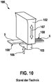
- FIG. 10 shows in a schematic simplified view of a prior art Ultraschall collgevorraum 100 for joining thermoplastic coated paper material.
- the apparatus 100 includes a prior art sonotrode 102 and an anvil 103 of the prior art. Between the sonotrode 102 and the anvil 103 is the paper material 5 to be joined, wherein thermoplastic layers 108 lie to one another.
- the paper material 5 is subjected to a joining force 106 in the gap between the sonotrode 102 and the anvil 103.
- the sonotrode 102 performs an ultrasonic vibration with a vibration direction 107.
- the vibration direction is 107 and the direction of the joining force 106 aligned parallel to each other.
- the longitudinal direction of movement of the sonotrode 102 is used here for the joining process.
- ultrasonic welding takes place with moistening of the joints. This allows a firm and clean joining of the paper material, without glue or thermoplastic coatings.
- the paper material consists in particular of paper, cardboard or cardboard.
- corrugated board can be used here.
- the method comprises the following steps: (i) forming a package from a blank of paper material, the paper material overlapping at at least one joint. (ii) positioning the at least one joint between a sonotrode and an anvil. (iii) applying the joining point with a joining force in a defined joining force direction.
- the paper material preferably on inner sides of joints, is moistened before the packaging is formed and / or during the molding of the packaging and / or after the packaging has been formed and / or during the ultrasonic friction welding.
- the moistening is preferably carried out with liquid water and / or water vapor and / or a moistening agent or the like. Particular preference is given to using pure water without additives. It is believed that ultrasonic welding at the joints will easily destroy the paper structure, forming a local pulp.
- this paper pulp allows a felting and thus a kind of gluing of the paper fibers, analogous to papermaking.
- a kind of compression of the joining surfaces leads to the formation of hydrogen bonds. This is often described as felting.
- the local formation of hydrogen bonds can be actively supported by moistening.
- adhesive joints of cardboard with the help of Dispersion adhesives (cold glue) and hot melt adhesives (hot glue) are used.
- hot glue hot melt adhesives
- the inventive method is particularly suitable for use in mass production for high volumes.
- the method according to the invention has the following advantages: According to the invention, no joining material is required, so that hot or cold glue can be substituted.
- the paper material requires no additional thermoplastic coating for the joining process by means of ultrasound. Conventional gluing machines are prone to fouling. Since no additives are preferred in the method of the present invention except for the preferred use of water for humidification, reduction of soiling and thus compliance with sanitary standards, which are of high importance to the food and pharmaceutical industries, can be achieved. It also follows that in the process according to the invention there is no risk of migration of joining agent (glue) into the packaged goods.
- the ultrasonic vibration generated by the sonotrode has a certain direction of vibration. Simultaneously with the application of the ultrasonic vibration via the sonotrode, the paper material in the gap between the sonotrode and the opposite anvil is subjected to a joining force. This joining force is aligned in a joining force direction.
- the oscillation direction and the joining force direction are not aligned parallel to one another. In the prior art, the direction of oscillation of the sonotrode is always formed parallel to the joining force direction.
- the longitudinal direction of movement of the oscillating particles is used for the energy production in the joint seam.
- the heat energy is generated from internal molecular and boundary surface friction of the joining partners.
- the thermal energy of the boundary surface friction is thereby obtained from the deformation energy of the deformation of the joining material via the anvil geometry.
- a friction welding method is used, in which the interface friction is used in the first place.
- the ultrasonic friction welding which is preferably used, has various advantages over ultrasonic longitudinal welding, in which the joining force direction is oriented parallel to the direction of oscillation of the sonotrode
- Ultrasonic friction welding can be used materials with low sound attenuation, which is the case especially for paper material. Due to the rubbing motion of the joined paper materials, no noise emission is detectable, as by the hammering movements of the sonotrode in longitudinal ultrasonic welding processes. The shear and peel strength of the joint is significantly higher in ultrasonic friction welding than in joint joints produced by conventional ultrasonic joining techniques.
- Another decisive advantage of ultrasonic friction welding is that the energy input into the paper material is used for the entire vibration, and not just the amplitude, which acts in the direction of the joint. Due to the avoidance of a hammering movement on the paper material to be joined, this paper material is protected in carrying out the ultrasonic friction welding.
- the joining force direction to the oscillation direction during ultrasonic friction welding is perpendicular or at right angles. Deviations of ⁇ 10 ° are still considered vertical here.
- This alignment ensures that the amplitudes of the vibrating sonotrode in both directions act as much as possible on the paper material.
- the vertical alignment of the joining force direction with respect to the direction of vibration ensures an almost exclusive use of the boundary surface friction at the joints.
- the ultrasonic vibration frequency of the sonotrode is preferably 20 to 40 kHz, more preferably between 30 and 35 kHz. Furthermore, it is preferably provided that the ultrasonic vibration amplitude of the sonotrode preferably between 10 and 50 ⁇ m, particularly preferably between 20 and 40 ⁇ m. Particularly in the case of these parameters for the ultrasound oscillation, an interface friction at the joints which is favorable for the joining of the paper material results.
- a common anvil and / or a common sonotrode is used for a plurality of mutually spaced joints. This makes it possible to add multiple joints simultaneously with only one anvil and / or with only one sonotrode. In particular, parallel joints are simultaneously processed by an anvil and / or a sonotrode.
- the invention further comprises a packaging device for producing a packaging from paper material according to the features of claim 6.
- the packaging device comprises a forming unit. This is preferably designed as thermoforming unit.
- the molding unit is for molding the package from a blank of paper material.
- the paper material is thereby formed so that it overlaps at least one joint.
- at least one sonotrode which can be set in ultrasound vibration is provided for ultrasonic welding of the paper material.
- at least one anvil is provided as a counter tool for the sonotrode.
- the joining force is generated by applying a corresponding force to the sonotrode and / or the anvil. The joining force acts in a joining force direction.
- the paper material preferably on inner sides of joints, is moistened by means of a moistening device before the packaging is formed and / or during the molding of the packaging and / or after the packaging has been formed and / or during the ultrasonic friction welding.
- the moistening is preferably carried out with liquid water and / or water vapor and / or a moistening agent or the like. Particular preference is given to using pure water without additives.
- the molding unit comprises a movable stamp plate for molding the packaging. At least one anvil or at least one sonotrode is arranged on this stamp plate. In a particularly preferred embodiment, it is provided that at least one anvil is provided on the stamp plate. The at least one sonotrode is then outside the mold unit. Thus, the at least one anvil is moved up and down together with the stamp plate. When joining the joints, the anvil is inside the molded package. The sonotrode attaches to the outside of the packaging.
- a feed unit is preferably provided. This serves to feed the blank to the molding unit. As already described, moistening of the joints preferably takes place. This is particularly preferably done in the feed unit.
- the feed unit therefore preferably comprises the device for moistening the joints during feeding.
- the packaging device preferably comprises a folding tool. With this folding tool parts of the blank can be folded so that, for example, tabs of the blank overlap. These overlapping tabs then form the joints.
- the sonotrode is preferably integrated in the folding tool.
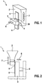
- FIG. 1 shows in highly simplified schematic view a detail of a packaging device 1 according to the embodiment. With this packaging device 1, the inventive method can be performed.
- the packaging device 1 comprises a sonotrode 2 and an anvil 3.
- a gap 4 is formed between the sonotrode 2 and the anvil 3.
- the paper material to be joined 5 Shown are two tabs 20 of a package 18 (s. FIGS. 6 and 7 ), which are inside the gap 4 overlap. These two tabs 20 are connected to each other by means of the packaging device 1.
- a joining force acts on the paper material 5 in the gap 4 via the anvil 3. This joining force is aligned in a joining force direction 6.
- the sonotrode 2 is excited to perform an ultrasonic vibration in the direction of vibration 7.
- This vibration direction 7 corresponds to the extension direction of the amplitudes of the ultrasonic vibration.
- this is an ultrasonic friction welding.
- ultrasonic longitudinal welding can also be carried out.
- the joining force direction 6 and the oscillation direction 7 are parallel to one another.
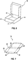
- FIG. 2 shows a detailed view FIG. 1 , also simplified schematically.
- the anvil 3 is acted upon by a cylinder rod 8, so that the anvil 3 can exert the joining force on the paper material 5 in the gap 4.
- the cylinder rod 8 is arranged parallel to the joining force 6.
- FIG. 2 schematically greatly simplifies the ability to moisten the paper material 5 with water 9. As already described, this moistening favors the joining process.
- FIG. 3 shows on the left side the principle of ultrasonic longitudinal welding.
- the amplitude of the ultrasonic vibration is not shown to scale to illustrate the principle of operation.
- the amplitude is for example between 20 and 40 microns.
- On the right in FIG. 3 the principle of ultrasonic friction welding is shown. It can be seen in this illustration that during ultrasonic longitudinal welding only the lower, positive amplitude in the direction of the paper material 5 can exert an effect. In the ultrasonic friction welding, however, takes place as in the Figures 1 and 2 shown, a lateral contact pressure of the paper material 5 to the sonotrode.
- both amplitude directions ie the extent in the positive amplitude direction and the Caribbean- or Pull back in the negative amplitude direction, effectively used for the joining process.
- By moistening the joints however, a good result can be achieved both with ultrasonic friction welding and with ultrasonic longitudinal welding.
- FIG. 4 shows in a diagram the test results in which a carton of 300 g / m 2 was tested in a device 100 according to the prior art and with a packaging device 1 according to the invention.
- the applied joining force in [N] is shown on the horizontal axis.
- the vertical axis shows the generated tensile strength in [N / 15 mm] of the joint.
- An upper curve 10 shows the result of the method according to the invention with moistened joints and ultrasonic friction welding.
- a lower trace 101 shows the result when using the device 100 according to the prior art.
- FIG. 5 shows the detailed design of the packaging device 1 according to the embodiment.
- the packaging device 1 comprises a forming unit 11, formed as a deep drawing unit.
- This forming unit 11 comprises a stamp plate 12.
- the stamp plate 12 is movable by means of a cylinder 13 in the vertical direction.
- the cylinder 13 is formed for example as a pneumatic or hydraulic cylinder.
- Below the stamp plate 12 is a carriage 14 of the packaging device 1. With this carriage 14, a folding tool 15 can be positioned.
- the packaging device 1 comprises a feed unit 16. About this feed unit 16 is a blank 19 (s. FIG. 7 ) are conveyed into the mold unit 11.
- the feed unit 16 comprises a moistening device 17. By means of this moistening device 17, the joints 21 (see FIG. FIG. 6 ) moistened.
- FIG. 5 the finished package 18, designed as a box.
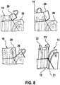
- this packaging is 18 in FIG. 6 shown.
- FIG. 6 has the package 18 at its edges joints 21. These joints 21 are joined by means of the sonotrode 2 and the anvil 3.
- FIG. 7 shows the blank 19 from which the package 18 is formed in the forming unit 11.
- the blank 19 is made of paper material 5, for example corrugated cardboard.
- On blank 19 a plurality of tabs 20 are provided. By means of the forming unit 11 and the folding tool 15, these tabs 20 are brought into overlap, so that the joints 21 arise.
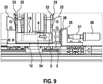
- FIG. 8 shows in several representations the folding process, which is performed by the folding tool 15.
- the stamp plate 12 of the molding unit 11 is hidden here for the sake of clarity.
- a first tab 20 is first folded at each joint 21.
- a second tab 20 is folded so that the two tabs 20 overlap and thus a joint 21 is formed.
- This folding or folding of the tabs 20 by means of forming shoulders 22 and plates 23 on the folding tool 15th
- FIG. 9 shows a detailed view FIG. 5 , FIG. 9 It can be seen that at least one anvil 3 is located on the stamp plate 12. This anvil 3 is moved over a short-stroke cylinder 24. This Kurzhubzylinder 24 is also located on the punch plate 12. In the schematically simplified representation according to FIG. 2 this Kurzhubzylinder 24 is shown only as a cylinder rod 8.
- the sonotrode 2 Outside the package 18 is the sonotrode 2. Furthermore, a hold-down 26 is provided. This hold-down device 26 is pressed against the sonotrode 2 via a sonotrode holder 25. This movement of the sonotrode holder 25 via a booster 27 and a converter 28. By the short-stroke cylinder 24 and the sonotrode holder 25 sonotrode 2 and anvil 3 can be moved towards each other. Between joint 2 and anvil 3 is the joint 21 of the packaging 18. The movements of the short-stroke cylinder 24 and the sonotrode holder 25 thus generate the joining force in the joining force 6. In this example shown, the joining force direction 6 is aligned horizontally. To join the joint 21, the sonotrode 2 in the marked vibration direction 7, that is perpendicular to the joining force 6, vibrated.
- the oscillation direction 7 and the joining force direction 6 are aligned parallel to one another
- FIG. 9 shows further that both the folding tool 15 and the sonotrode 2 are integrated with sonotrode holder 25 in a tool.
Landscapes
- Engineering & Computer Science (AREA)
- Mechanical Engineering (AREA)
- Package Closures (AREA)
- Lining Or Joining Of Plastics Or The Like (AREA)
- Making Paper Articles (AREA)
Description
- Die vorliegende Erfindung betrifft ein Verfahren zum Herstellen einer Verpackung und eine entsprechende Verpackungsmaschine. Bei dem Verfahren und in der Verpackungsmaschine wir mittels einem Ultraschallfügeverfahren Papiermaterial, insbesondere Papier, Karton oder Pappe, verbunden.
- In
EP 0 340 334 A2 wird eine Vorrichtung beschrieben, die sich zum Verbinden von zwei- oder mehrlagigen Papiererzeugnissen mittels Ultraschall eignet. Das verwendete Papier ist dabei mit einer thermoplastischen Beschichtung versehen. Mittels der Sonotrode werden dabei Longitudinalwellen erzeugt, so dass sich die Sonotrode bei der Ultraschallschwingung auf den Amboss zu und wieder von dem Amboss wegbewegt. Durch die entsprechende Ultraschallfrequenz und den entsprechenden Anpressdruck wird hier eine ausreichende Verdichtung der Papierlagen erzeugt. Gleichzeitig kommt es zu einer hohen Wärmeentwicklung im Mikrobereich der thermoplastischen Beschichtung und somit zum Verkleben der Papierlagen. - Beiliegende
Figur 10 zeigt in schematisch vereinfachter Ansicht eine Ultraschallfügevorrichtung 100 nach dem Stand der Technik zum Verbinden von thermoplastisch beschichtetem Papiermaterial. Die Vorrichtung 100 umfasst eine Sonotrode 102 nach dem Stand der Technik und einen Amboss 103 nach dem Stand der Technik. Zwischen der Sonotrode 102 und dem Amboss 103 befindet sich das zu fügende Papiermaterial 5, wobei thermoplastische Schichten 108 zueinander liegen. Das Papiermaterial 5 wird in dem Spalt zwischen Sonotrode 102 und Amboss 103 mit einer Fügekraft 106 beaufschlagt. Die Sonotrode 102 führt eine Ultraschallschwingung mit einer Schwingungsrichtung 107 aus. In der Vorrichtung 100 nach dem Stand der Technik sind die Schwingungsrichtung 107 und die Richtung der Fügekraft 106 parallel zueinander ausgerichtet. Es wird hier also die longitudinale Bewegungsrichtung der Sonotrode 102 für den Fügeprozess genutzt. - Aus der
US 3533207 wird zunächst aus einem Zuschnitt eine entsprechende Verpackung geformt. Überlappende Bereiche des Zuschnitts werden daraufhin gefügt. Bei derWO 99/25547 A1 - Beim dem erfindungsgemäßen Verfahren und der erfindungsgemäßen Vorrichtung erfolgt ein Ultraschallschweißen mit einer Befeuchtung der Fügestellen. Dies ermöglicht ein festes und sauberes Fügen des Papiermaterials, ohne Klebstoff oder thermoplastischer Beschichtungen. Diese Vorteile werden erreicht durch ein Verfahren zum Herstellen einer Verpackung aus Papiermaterial. Das Papiermaterial besteht insbesondere aus Papier, Karton oder Pappe. Insbesondere kann hier Wellpappe verwendet werden. Das Verfahren umfasst folgende Schritte: (i) Formen einer Verpackung aus einem Zuschnitt aus Papiermaterial, wobei das Papiermaterial an zumindest einer Fügestelle überlappt. (ii) Positionieren der zumindest einen Fügestelle zwischen einer Sonotrode und einem Amboss. (iii) Beaufschlagen der Fügestelle mit einer Fügekraft in einer definierten Fügekraftrichtung. (iv) Versetzen der Sonotrode in eine Ultraschallschwingung zum Ultraschallschweißen des Papiermaterials an der Fügestelle. Erfindungsgemäß ist vorgesehen, dass das Papiermaterial, vorzugsweise an Innenseiten von Fügestellen, vor dem Formen der Verpackung und/oder während dem Formen der Verpackung und/oder nach dem Formen der Verpackung und/der während des Ultraschallreibschweißens, befeuchtet wird. Das Befeuchten erfolgt vorzugsweise mit flüssigem Wasser und/oder Wasserdampf und/oder einem Befeuchtungsmittel oder ähnlichem. Besonders bevorzugt wird reines Wasser ohne Zusätze verwendet. Es wird angenommen, dass durch das Ultraschallschweißen an den Fügestellen die Papierstruktur leicht zerstört wird und sich so ein lokaler Papierbrei bildet. Dieser Papierbrei ermöglicht infolge der Einwirkung des Ultraschalls und des Drucks durch die Fügekraft eine Verfilzung und somit eine Art Verleimung der Papierfasern, analog zur Papierherstellung. Eine Art Verdichtung der Fügeflächen führt zur Ausbildung von Wasserstoffbrücken. Dies wird vielmals auch als Verfilzung beschrieben. Die lokale Ausbildung von Wasserstoffbrücken kann durch das Befeuchten aktiv unterstützt werden. Insbesondere in der Verpackungsindustrie kommen zahlreiche Arten von Klebeverbindungen von Kartonagen mit Hilfe von Dispersionsklebstoffen (Kaltleim) und Schmelzklebstoffen (Heißleim) zum Einsatz. Um den Verpackungsprozess zu rationalisieren, sauberer und hygienischer zu gestalten, kann das Ultraschallschweißverfahren gemäß vorliegender Erfindung mit befeuchteten Fügestellen eingesetzt werden. Durch die kurzen Zyklen im Bereich von 0,1 bis 1 Sekunde und Haltezeiten von 0,1 bis 2 Sekunden ist das erfindungsgemäße Verfahren besonders für den Einsatz in der Serienproduktion für hohe Stückzahlen geeignet. Gegenüber dem Klebeverfahren hat das erfindungsgemäße Verfahren die folgenden Vorteile: Es wird erfindungsgemäß kein Fügematerial benötigt, so dass Heiß- bzw. Kaltleim substituiert werden kann. Das Papiermaterial benötigt für den Fügevorgang mittels Ultraschall keine zusätzliche thermoplastische Beschichtung. Herkömmliche Klebemaschinen neigen stark zum Verschmutzen. Da beim erfindungsgemäße Verfahren bevorzugt keine Zusatzstoffe verwendet werden, mit Ausnahme der bevorzugten Anwendung von Wasser zur Befeuchtung, kann eine Verringerung der Verschmutzung und somit das Einhalten der hygienischen Standards, die für die Lebensmittel- und Pharmaindustrie von hoher Bedeutung sind, erzielt werden. Daraus ergibt sich auch, dass beim erfindungsgemäßen Verfahren nicht die Gefahr einer Migration von Fügemittel (Leim) in das Packgut besteht. Des Weiteren ergibt sich eine hohe Energieeinsparung, da kein kontinuierliches Aufheizen des Heißleims notwendig ist. Die für das Verfahren notwendige Energie wird nur im Bereich der Fügezeit, also im Millisekundenbereich, benötigt. Die von der Sonotrode erzeugte Ultraschallschwingung weist eine bestimmte Schwingungsrichtung auf. Gleichzeitig mit dem Aufbringen der Ultraschallschwingung über die Sonotrode wird das Papiermaterial im Spalt zwischen der Sonotrode und dem gegenüberliegenden Amboss mit einer Fügekraft beaufschlagt. Diese Fügekraft ist in einer Fügekraftrichtung ausgerichtet. In einer erfinungsgemäßen Variante ist vorgesehen, dass die Schwingungsrichtung und die Fügekraftrichtung nicht parallel zueinander ausgerichtet sind. Im Stand der Technik ist stets die Schwingungsrichtung der Sonotrode parallel zur Fügekraftrichtung ausgebildet. Dadurch wird im Stand der Technik hauptsächlich die longitudinale Bewegungsrichtung der schwingenden Teilchen für die Energieerzeugung in der Fügenaht genutzt. Dabei wird die Wärmeenergie aus Innermolekularer- und Grenzflächenreibung der Fügepartner erzeugt. Die Wärmeenergie der Grenzflächenreibung wird dabei aus der Verformungsenergie der Deformation des Fügematerials über die Ambossgeometrie gewonnen. Dem gegenüber wurde im Rahmen der Erfindung erkannt, dass ein sehr viel besseres Fügen von Papiermaterial möglich ist, wenn ein Reibschweißverfahren eingesetzt wird, bei dem in erster Linie die Grenzflächenreibung genutzt wird. Das bevorzugt verwendete Ultraschallreibschweißen weist gegenüber dem Ultraschalllongitudinalschweißen, bei dem die Fügekraftrichtung parallel zur Schwingungsrichtung der Sonotrode ausgerichtet ist, diverse Vorteile auf: Beim Ultraschallreibschweißen können Materialien mit geringer Schalldämpfung verwendet werden, was insbesondere bei Papiermaterial der Fall ist. Infolge der Reibbewegung der gefügten Papiermaterialien ist keine Lärmemission, wie durch die hämmernden Bewegungen der Sonotrode bei longitudinalen Ultraschallschweißverfahren, feststellbar. Die Scher- und Schälfestigkeit der Fügeverbindung ist beim Ultraschallreibschweißen deutlich höher als bei Fügeverbindungen, die mit üblichen Ultraschallfügeverfahren erzeugt wurden. Ein weiterer entscheidender Vorteil bei dem Ultraschallreibschweißen ist, dass für den Energieeintrag in das Papiermaterial die gesamte Schwingung, und nicht nur die Amplitude, die in Richtung der Fügestelle wirkt, genutzt wird. Infolge der Vermeidung einer hämmernden Bewegung auf das zu fügende Papiermaterial, wird dieses Papiermaterial beim Durchführen des Ultraschallreibschweißens geschont.
- Die Unteransprüche zeigen bevorzugte Weiterbildungen der Erfindung.
- Insbesondere ist vorgesehen, dass die Fügekraftrichtung zur Schwingungsrichtung beim Ultraschallreibschweißen senkrecht bzw. rechtwinklig steht. Abweichungen von ±10° werden hier noch als senkrecht angesehen. Durch diese Ausrichtung wird sichergestellt, dass die Amplituden der schwingenden Sonotrode in beiden Richtungen weitestgehend auf das Papiermaterial wirken. Gleichzeitig sorgt die senkrechte Ausrichtung der Fügekraftrichtung zur Schwingungsrichtung für eine annähernd ausschließliche Nutzung der Grenzflächenreibung an den Fügestellen.
- Die Ultraschallschwingungsfrequenz der Sonotrode liegt vorzugsweise bei 20 bis 40 kHz, besonders vorzugsweise zwischen 30 und 35 kHz. Des Weiteren ist bevorzugt vorgesehen, dass die Ultraschallschwingungsamplitude der Sonotrode vorzugsweise zwischen 10 und 50 µm, besonders vorzugsweise zwischen 20 und 40 µm, liegt. Insbesondere bei diesen Parametern für die Ultraschallschwingung entsteht eine für das Fügen des Papiermaterials günstige Grenzflächenreibung an den Fügestellen.
- Das erfindungsgemäße Anwenden des Ultraschallschweißens bei Papiermaterial mit Befeuchtung führt zu sehr stabilen Fügestellen, so dass bevorzugt auf die Verwendung von Klebstoff oder thermoplastischen Beschichtungen verzichtet wird. Des Weiteren ist es auch nicht notwendig, dass sich an den Fügestellen Druckerfarbe auf dem Papiermaterial befindet, die ähnlich einer thermoplastischen Beschichtung ein Verkleben der Papiermaterialien begünstigen würde.
- Vorzugsweise wird für mehrere, voneinander beabstandete Fügestellen ein gemeinsamer Amboss und/oder eine gemeinsame Sonotrode verwendet. Dadurch ist es möglich, mit nur einem Amboss und/oder mit nur einer Sonotrode mehrere Fügestellen gleichzeitig zu fügen. Insbesondere werden parallele Fügestellen gleichzeitig von einem Amboss und/oder einer Sonotrode bearbeitet.
- Die Erfindung umfasst des Weiteren eine Verpackungsvorrichtung zum Herstellen einer Verpackung aus Papiermaterial gemäß den Merkmalen des Anspruchs 6. Die Verpackungsvorrichtung umfasst eine Formeinheit. Diese ist vorzugsweise ausgebildet als Tiefzieheinheit. Die Formeinheit dient zum Formen der Verpackung aus einem Zuschnitt aus Papiermaterial. Das Papiermaterial wird dabei so geformt, dass es an zumindest einer Fügestelle überlappt. Ferner ist zumindest eine in Ultraschallschwingung versetzbare Sonotrode zum Ultraschallschweißen des Papiermaterials vorgesehen. Des Weiteren ist zumindest ein Amboss als Gegenwerkzeug für die Sonotrode vorgesehen. Die Fügekraft wird erzeugt durch ein Beaufschlagen der Sonotrode und/oder des Ambosses mit einer entsprechenden Kraft. Die Fügekraft wirkt dabei in einer Fügekraftrichtung. Erfindungsgemäß ist vorgesehen, dass das Papiermaterial, vorzugsweise an Innenseiten von Fügestellen, vor dem Formen der Verpackung und/oder während dem Formen der Verpackung und/oder nach dem Formen der Verpackung und/der während des Ultraschallreibschweißens, mittels einer Befeuchtungsvorrichtung befeuchtet wird. Das Befeuchten erfolgt vorzugsweise mit flüssigem Wasser und/oder Wasserdampf und/oder einem Befeuchtungsmittel oder ähnlichem. Besonders bevorzugt wird reines Wasser ohne Zusätze verwendet.
- Die im Rahmen des erfindungsgemäßen Verfahrens vorgestellten Unteransprüche und vorteilhaften Ausbildungen finden entsprechend vorteilhafte Anwendung auf die erfindungsgemäße Verpackungsvorrichtung.
- Insbesondere ist vorgesehen, dass die Formeinheit eine verfahrbare Stempelplatte zum Formen der Verpackung umfasst. Auf dieser Stempelplatte ist zumindest ein Amboss oder zumindest eine Sonotrode angeordnet. In besonders bevorzugter Ausführung ist vorgesehen, dass auf der Stempelplatte zumindest ein Amboss vorgesehen ist. Die zumindest eine Sonotrode befindet sich sodann außerhalb der Formeinheit. Somit wird der zumindest eine Amboss zusammen mit der Stempelplatte auf und ab bewegt. Beim Fügen der Fügestellen befindet sich der Amboss innerhalb der geformten Verpackung. Die Sonotrode setzt außen an der Verpackung an.
- Des Weiteren ist bevorzugt eine Zuführeinheit vorgesehen. Diese dient zum Zuführen des Zuschnitts zur Formeinheit. Wie bereits beschrieben, erfolgt bevorzugt ein Befeuchten der Fügestellen. Dies erfolgt besonders bevorzugt in der Zuführeinheit. Die Zuführeinheit umfasst deshalb bevorzugt die Vorrichtung zum Befeuchten der Fügestellen während dem Zuführen.
- Des Weiteren umfasst die Verpackungsvorrichtung bevorzugt ein Faltwerkzeug. Mit diesem Faltwerkzeug können Teile des Zuschnitts gefaltet werden, so dass sich beispielsweise Laschen des Zuschnitts überlappen. Diese überlappenden Laschen bilden dann die Fügestellen. Die Sonotrode ist vorzugsweise in das Faltwerkzeug integriert.
- Nachfolgend wird ein Ausführungsbeispiel der Erfindung unter Bezugnahme auf die begleitende Zeichnung im Detail beschrieben. Dabei zeigen:
- Figur 1
- ein schematisch vereinfachtes Detail einer erfindungsgemäßen Verpackungsvorrichtung zur Durchführung des erfindungsgemäßen Verfahrens gemäß einem Ausführungsbeispiel;
- Figur 2
- eine Detailansicht zu
Figur 1 ; - Figur 3
- eine Gegenüberstellung von Ultraschalllongitudinalschweißen und Ultraschallreibschweißen;
- Figur 4
- ein Diagramm zur Zugfestigkeit der erzeugten Fügestelle,
- Figur 5
- die erfindungsgemäße Verpackungsvorrichtung zur Durchführung des erfindungsgemäßen Verfahrens gemäß dem Ausführungsbeispiel,
- Figur 6
- eine fertige Verpackung, wie sie mit der erfindungsgemäßen Verpackungsvorrichtung gemäß dem Ausführungsbeispiel herstellbar ist,
- Figur 7
- einen Zuschnitt, der in der erfindungsgemäßen Verpackungsvorrichtung zur Verpackung gefaltet wird,
- Figur 8
- mehrere Darstellungen des Faltprozesses, wie er von der erfindungsgemäßen Verpackungsvorrichtung gemäß dem Ausführungsbeispiel durchgeführt wird,
- Figur 9
- eine Detailansicht zu
Figur 5 , und - Figur 10
- eine Ultraschallfügevorrichtung gemäß dem Stand der Technik.
-
Figur 1 zeigt in stark schematisch vereinfachter Ansicht ein Detail einer Verpackungsvorrichtung 1 nach dem Ausführungsbeispiel. Mit dieser Verpackungsvorrichtung 1 kann das erfindungsgemäße Verfahren durchgeführt werden. - Die Verpackungsvorrichtung 1 umfasst eine Sonotrode 2 und einen Amboss 3. Zwischen der Sonotrode 2 und dem Amboss 3 ist ein Spalt 4 ausgebildet. In diesem Spalt 4 befindet sich das zu fügende Papiermaterial 5. Gezeigt sind zwei Laschen 20 einer Verpackung 18 (s.
Figuren 6 und 7 ), die innerhalb des Spaltes 4 überlappen. Diese beiden Laschen 20 werden mittels der Verpackungsvorrichtung 1 miteinander verbunden. - Über den Amboss 3 wirkt eine Fügekraft auf das Papiermaterial 5 im Spalt 4. Diese Fügekraft ist in einer Fügekraftrichtung 6 ausgerichtet.
- Die Sonotrode 2 wird zur Durchführung einer Ultraschallschwingung in Schwingungsrichtung 7 angeregt. Diese Schwingungsrichtung 7 entspricht der Ausdehnungsrichtung der Amplituden der Ultraschallschwingung.
- Wie
Figur 1 gut zu entnehmen ist, steht die Fügekraftrichtung 6 senkrecht auf (auch: rechtwinklig zu) der Schwingungsrichtung 7. Somit handelt es sich hier um ein Ultraschallreibschweißverfahren. Wie bereits beschrieben, kann auch ein Ultraschalllongitudinalschweißen durchgeführt werde. Dabei sind dann die Fügekraftrichtung 6 und die Schwingungsrichtung 7 parallel zueinander. -
Figur 2 zeigt eine Detailansicht zuFigur 1 , ebenfalls schematisch vereinfacht. GemäßFigur 2 wird der Amboss 3 über eine Zylinderstange 8 beaufschlagt, so dass der Amboss 3 die Fügekraft auf das Papiermaterial 5 im Spalt 4 ausüben kann. Dementsprechend ist auch die Zylinderstange 8 parallel zur Fügekraftrichtung 6 angeordnet. - Des Weiteren zeigt
Figur 2 schematisch stark vereinfacht die Möglichkeit, das Papiermaterial 5 mit Wasser 9 zu befeuchten. Wie bereits beschrieben, begünstigt dieses Befeuchten den Fügeprozess. -
Figur 3 zeigt auf der linken Seite das Prinzip des Ultraschalllongitudinalschweißens. Die Amplitude der Ultraschallschwingung ist zur Verdeutlichung des Funktionsprinzips nicht maßstäblich dargestellt. Die Amplitude beträgt beispielsweise zwischen 20 und 40 µm. Auf der rechten Seite inFigur 3 ist das Prinzip des Ultraschallreibschweißens dargestellt. Man erkennt in dieser Darstellung, dass beim Ultraschalllongitudinalschweißen nur die untere, positive Amplitude in Richtung des Papiermaterials 5 eine Wirkung entfalten kann. Bei dem Ultraschallreibschweißen dagegen erfolgt, wie in denFiguren 1 und 2 gezeigt, eine seitliche Anpressung des Papiermaterials 5 an die Sonotrode. Infolgedessen können beide Amplitudenrichtungen, also die Ausdehnung in der positiven Amplitudenrichtung und das Zusammen- oder Zurückziehen in der negativen Amplitudenrichtung, effektiv für den Fügeprozess genutzt werden. Durch die Befeuchtung der Fügestellen kann allerdings sowohl mit dem Ultraschallreibschweißens als auch mit dem Ultraschalllongitudinalschweißen ein gutes Ergebnis erzielt werden. -
Figur 4 zeigt in einem Diagramm die Versuchsergebnisse, bei denen ein Karton mit 300 g/m2 in einer Vorrichtung 100 nach dem Stand der Technik und mit einer Verpackungsvorrichtung 1 gemäß der Erfindung getestet wurde. Auf der horizontalen Achse ist die aufgebrachte Fügekraft in [N] eingezeichnet. Die vertikale Achse zeigt die erzeugte Zugfestigkeit in [N/15 mm] der Fügestelle. Ein oberer Verlauf 10 zeigt das Ergebnis des erfindungsgemäßen Verfahrens mit befeuchteten Fügestellen und Ultraschallreibschweißen. Ein unterer Verlauf 101 zeigt das Ergebnis bei Verwendung der Vorrichtung 100 nach dem Stand der Technik. - Im Rahmen der Erfindung und in experimentellen Untersuchungen hat sich gezeigt, dass sich Papier, Karton und Pappe besser miteinander verbinden lassen, wenn ein Ultraschallreibschweißen als Fügeverfahren verwendet wird. Im Gegensatz zum Ultraschalllongitudinalschweißen ist dabei die Schwingungsrichtung 7 nicht parallel zur Fügekraftrichtung 6, sondern bevorzugt senkrecht (auch: rechtwinklig) dazu. Die Festigkeitswerte der Verbindung sind im Bezug auf die Scher- und Schälfestigkeit gegenüber den longitudinalen Ultraschallschweißverfahren deutlich erhöht. Zudem sind, wie
Figur 4 zeigt, auch im Bereich von niedrigen Fügekräften relativ hohe Zugfestigkeiten zu erreichen. - Aufgrund von durchgeführten Versuchen wird angenommen, dass für die Verbindung mit relativ hoher Zugfestigkeit nicht nur die Mikroverspleißung der Fasern und neue Wasserstoffbrücken ausschlaggebend sind. Die Ergebnisse sprechen für ein Plastifizieren und Erstarren von fasereigenen Polymeren, natürlichen oder synthetischen Bindemitteln sowie polymerartigen Additiven. Man kann davon ausgehen, dass sich während des Fügeprozesses auf den sich berührenden Oberflächen plastifizierte Bereiche befinden. Der longitudinale Ultraschallfügevorgang beansprucht die Fügepartner mit einer erhöhten Tiefenwirkung. Für eine Verbesserung der Verbindungsqualität ist es zielführender, die mechanische Beanspruchung parallel zur Fügeebene wirken zu lassen, wie dies im Rahmen vorliegender Erfindung gezeigt wurde. Ein weiterer wesentlicher Vorteil, der für die seitliche Anpressung der Sonotrode 2 an das Papiermaterial 5 spricht, ist die vollständige Nutzung der Sonotrodenschwingungen in beide Amplitudenrichtungen. Beim Ultraschallreibschweißen wird von der im Schwingungsgebilde erzeugten stehenden Welle sowohl die Expansions- als auch die Kontraktionsbewegung genutzt. Wird die Sonotrode beim longitudinalen Ultraschallschweißen gegen die Fügepartner gepresst, wirkt sich nur die Expansion auf den Schweißvorgang aus, bei der Kontraktion verliert die Sonotrode den Kontakt zum Papiermaterial. Somit kann bei dem Ultraschallreibschweißen eine Verdopplung der wirksamen Amplitude erreicht werden, von beispielsweise 24 µm auf 48 µm bei 30 kHz.
-
Figur 5 zeigt die genaue Ausbildung der Verpackungsvorrichtung 1 gemäß dem Ausführungsbeispiel. Gemäß dieser Darstellung umfasst die Verpackungsvorrichtung 1 eine Formeinheit 11, ausgebildet als Tiefzieheinheit. Diese Formeinheit 11 umfasst eine Stempelplatte 12. Die Stempelplatte 12 ist mittels eines Zylinders 13 in vertikaler Richtung verfahrbar. Der Zylinder 13 ist beispielsweise als Pneumatik- oder Hydraulikzylinder ausgebildet.
Unterhalb der Stempelplatte 12 befindet sich ein Führungswagen 14 der Verpackungsvorrichtung 1. Mit diesem Führungswagen 14 ist ein Faltwerkzeug 15 positionierbar. - Des Weiteren umfasst die Verpackungsvorrichtung 1 eine Zuführeinheit 16. Über diese Zuführeinheit 16 wird ein Zuschnitt 19 (s.
Figur 7 ) in die Formeinheit 11 befördert. - Die Zuführeinheit 16 umfasst eine Befeuchtungsvorrichtung 17. Mittels dieser Befeuchtungsvorrichtung 17 werden die Fügestellen 21 (s.
Figur 6 ) befeuchtet. - Des Weiteren zeigt
Figur 5 die fertige Verpackung 18, ausgebildet als Schachtel. Im Detail ist diese Verpackung 18 inFigur 6 dargestellt. GemäßFigur 6 weist die Verpackung 18 an ihren Kanten Fügestellen 21 auf. Diese Fügestellen 21 werden mittels der Sonotrode 2 und dem Amboss 3 gefügt. -
Figur 7 zeigt den Zuschnitt 19, aus dem in der Formeinheit 11 die Verpackung 18 geformt wird. Der Zuschnitt 19 besteht aus Papiermaterial 5, beispielsweise Wellpappe. Am Zuschnitt 19 sind mehrere Laschen 20 vorgesehen. Mittels der Formeinheit 11 und dem Faltwerkzeug 15 werden diese Laschen 20 in Überlappung gebracht, so dass die Fügestellen 21 entstehen. -
Figur 8 zeigt in mehreren Darstellungen den Faltprozess, der vom Faltwerkzeug 15 durchgeführt wird. Die Stempelplatte 12 der Formeinheit 11 ist hier der Übersichtlichkeit halber ausgeblendet. WieFigur 8 zeigt, wird an jeder Fügestelle 21 zunächst eine erste Lasche 20 geklappt. Daraufhin wird eine zweite Lasche 20 geklappt, so dass die beiden Laschen 20 überlappen und somit eine Fügestelle 21 entsteht. Dieses Falten bzw. Klappen der Laschen 20 erfolgt mittels Formschultern 22 und Blechen 23 am Faltwerkzeug 15. -
Figur 9 zeigt eine Detailansicht zuFigur 5 .Figur 9 ist zu entnehmen, dass sich auf der Stempelplatte 12 zumindest ein Amboss 3 befindet. Dieser Amboss 3 wird über einen Kurzhubzylinder 24 bewegt. Dieser Kurzhubzylinder 24 befindet sich ebenfalls auf der Stempelplatte 12. In der schematisch vereinfachten Darstellung gemäßFigur 2 ist dieser Kurzhubzylinder 24 lediglich als Zylinderstange 8 dargestellt. - Außerhalb der Verpackung 18 befindet sich die Sonotrode 2. Ferner ist ein Niederhalter 26 vorgesehen. Dieser Niederhalter 26 wird über einen Sonotrodenhalter 25 gegen die Sonotrode 2 gedrückt. Diese Bewegung des Sonotrodenhalters 25 erfolgt über einen Booster 27 und einen Konverter 28. Durch den Kurzhubzylinder 24 und den Sonotrodenhalter 25 können Sonotrode 2 und Amboss 3 aufeinander zubewegt werden. Zwischen Sonotrode 2 und Amboss 3 befindet sich die Fügestelle 21 der Verpackung 18. Die Bewegungen des Kurzhubzylinders 24 und des Sonotrodenhalters 25 erzeugen somit die Fügekraft in Fügekraftrichtung 6. In diesem gezeigten Beispiel ist die Fügekraftrichtung 6 horizontal ausgerichtet. Zum Fügen der Fügestelle 21 wird die Sonotrode 2 in der eingezeichneten Schwingungsrichtung 7, also senkrecht zur Fügekraftrichtung 6, in Schwingung versetzt.
- Alternativ ist auch vorgesehen, dass für ein Ultraschalllongitudinalschweißen die Schwingungsrichtung 7 und die Fügekraftrichtung 6 parallel zueinander ausgerichtet sind
-
Figur 9 zeigt des Weiteren, dass sowohl das Faltwerkzeug 15 als auch die Sonotrode 2 mit Sonotrodenhalter 25 in einem Werkzeug integriert sind.
Claims (9)
- Verfahren zum Herstellen einer Verpackung (18) aus Papiermaterial (5), insbesondere Papier, Karton oder Pappe, umfassend die folgenden Schritte:- Formen einer Verpackung (18) aus einem Zuschnitt (19) aus Papiermaterial (5), wobei das Papiermaterial an zumindest einer Fügestelle (21) überlappt,- Positionieren der zumindest einen Fügestelle (21) zwischen einer Sonotrode (2) und einem Amboss (3),- Beaufschlagen der Fügestelle (21) mit einer Fügekraft in einer Fügekraftrichtung (6), und- Versetzen der Sonotrode (2) in eine Ultraschallschwingung zum Ultraschallschweißen des Papiermaterials (5) an der Fügestelle (21),dadurch gekennzeichnet,- dass das Papiermaterial (5), vorzugsweise an Innenseiten der Fügestellen (21), vor dem Formen der Verpackung (18) und/oder während dem Formen der Verpackung (18) und/oder nach dem Formen der Verpackung (18) und/oder während dem Ultraschallschweißen befeuchtet wird und- dass ein Ultraschallreibschweißen durchgeführt wird, bei dem die Fügekraftrichtung (6) zur Schwingungsrichtung (7) der Ultraschallschwingung nicht parallel ist.
- Verfahren nach Anspruch 1, dadurch gekennzeichnet, dass die Fügekraftrichtung (6) zur Schwingungsrichtung (7), mit einer maximalen Abweichung von +/- 10°, senkrecht steht.
- Verfahren nach einem der vorhergehenden Ansprüche, dadurch gekennzeichnet, dass die Ultraschallschwingungsfrequenz der Sonotrode (2) zwischen 20 und 40 kHz, vorzugsweise zwischen 30 und 35 kHz, liegt.
- Verfahren nach einem der vorhergehenden Ansprüche, dadurch gekennzeichnet, dass zum Ultraschallschweißen des Papiermaterials (5) kein Klebstoff, kein Thermoplast und vorzugsweise auch keine Druckfarbe, verwendet wird.
- Verfahren nach einem der vorhergehenden Ansprüche, dadurch gekennzeichnet, dass für mehrere, voneinander beabstandete Fügestellen (21) ein gemeinsamer Amboss (3) und/oder eine gemeinsame Sonotrode (2) verwendet wird.
- Verpackungsvorrichtung (1) zum Herstellen ein Verpackung (18) aus Papiermaterial (5), insbesondere Papier, Karton oder Pappe, umfassend- eine Formeinheit (11), vorzugsweise ausgebildet als Tiefzieheinheit, zum Formen einer Verpackung (18) aus einem Zuschnitt (19) aus Papiermaterial (5), wobei das Papiermaterial (5) an zumindest einer Fügestelle (21) überlappt,- zumindest eine in Ultraschallschwingung versetzbare Sonotrode (2) zum Ultraschallschweißen des Papiermaterials (5) an der Fügestelle (21), und- zumindest einen Amboss (3),- wobei an der zumindest einen Fügestelle (21) zwischen Sonotrode (2) und Amboss (3) durch Beaufschlagen der Sonotrode (2) und/oder des Ambosses (3) eine Fügekraft auf das Papiermaterial (5) in einer Fügekraftrichtung (6) wirkt,dadurch gekennzeichnet,- dass das Papiermaterial (5), vorzugsweise an Innenseiten der Fügestellen (21), vor dem Formen der Verpackung (18) und/oder während dem Formen der Verpackung (18) und/oder nach dem Formen der Verpackung (18) und/oder während dem Ultraschallschweißen mittels einer Befeuchtungsvorrichtung (17) befeuchtet wird und- dass Sonotrode (2) und Amboss (3) für ein Ultraschallreibschweißen angeordnet und eingerichtet sind, bei dem die Fügekraftrichtung (6) zur Schwingungsrichtung (7) der Ultraschallschwingung nicht parallel ist.
- Verpackungsvorrichtung nach Anspruch 6, dadurch gekennzeichnet, dass die Formeinheit (11) eine verfahrbare Stempelplatte (12) zum Formen der Verpackung (18) umfasst, wobei auf der Stempelplatte (12) zumindest ein Amboss (3) oder zumindest eine Sonotrode (2) angeordnet sind.
- Verpackungsvorrichtung nach einem der Ansprüche 6 oder 7,
gekennzeichnet durch eine Zuführeinheit (16) zum Zuführen des Zuschnitts (19) zur Formeinheit (11), wobei die Zuführeinheit (16) die Befeuchtungsvorrichtung (17) zum Befeuchten der Fügestellen (21) während dem Zuführen umfasst. - Verpackungsvorrichtung nach einem der Ansprüche 6 bis 8,
gekennzeichnet durch ein Faltwerkzeug (15) zum Überlappen des Papiermaterials (5) an den Fügestellen (21), wobei zumindest eine Sonotrode (2) oder zumindest ein Amboss (3) in das Faltwerkzeug (15) integriert sind.
Applications Claiming Priority (2)
| Application Number | Priority Date | Filing Date | Title |
|---|---|---|---|
| DE102013225737.6A DE102013225737A1 (de) | 2013-12-12 | 2013-12-12 | Verfahren zum Herstellen einer Verpackung und Verpackungsmaschine |
| PCT/EP2014/076276 WO2015086381A1 (de) | 2013-12-12 | 2014-12-02 | Verfahren zum herstellen einer verpackung und verpackungsmaschine |
Publications (2)
| Publication Number | Publication Date |
|---|---|
| EP3079895A1 EP3079895A1 (de) | 2016-10-19 |
| EP3079895B1 true EP3079895B1 (de) | 2019-04-10 |
Family
ID=52014065
Family Applications (1)
| Application Number | Title | Priority Date | Filing Date |
|---|---|---|---|
| EP14808939.4A Active EP3079895B1 (de) | 2013-12-12 | 2014-12-02 | Verfahren zum herstellen einer verpackung und verpackungsmaschine |
Country Status (5)
| Country | Link |
|---|---|
| US (1) | US10723096B2 (de) |
| EP (1) | EP3079895B1 (de) |
| CN (1) | CN106029356B (de) |
| DE (1) | DE102013225737A1 (de) |
| WO (1) | WO2015086381A1 (de) |
Families Citing this family (8)
| Publication number | Priority date | Publication date | Assignee | Title |
|---|---|---|---|---|
| DE102015223070A1 (de) | 2015-11-23 | 2017-05-24 | Robert Bosch Gmbh | Vorrichtung und Verfahren zum Fügen von Papiermaterial, insbesondere Papier, Karton oder Pappe |
| US10647079B2 (en) | 2016-12-08 | 2020-05-12 | General Mills, Inc. | Method of ultrasonically bonding paperboard |
| DE102019202850A1 (de) | 2019-03-01 | 2020-09-03 | Syntegon Technology Gmbh | Verfahren und Vorrichtung zum Fügen von Papiermaterial |
| DE102019202847A1 (de) * | 2019-03-01 | 2020-09-03 | Syntegon Technology Gmbh | Schlauchbeutelmaschine zur Herstellung von Papierbeuteln |
| CN109732990B (zh) * | 2019-03-13 | 2023-12-22 | 浙江国豪机械有限公司 | 一种包装盒成型机用超声波定型设备 |
| CN113212869B (zh) * | 2021-05-17 | 2024-09-10 | 王骏桃 | 一种棒棒产品的包装流水线设备 |
| CN114309913B (zh) * | 2022-01-19 | 2023-03-28 | 合肥宏灿包装机械有限公司 | 一种食品包装盒加工用的超声波焊接机 |
| CN114801323A (zh) * | 2022-05-12 | 2022-07-29 | 贵州富强科技包装有限公司 | 一种纸杯纸碗成型机前预处理发水装置 |
Citations (6)
| Publication number | Priority date | Publication date | Assignee | Title |
|---|---|---|---|---|
| CH399988A (de) * | 1961-12-11 | 1965-09-30 | Hesser Ag Maschf | Verfahren zum Herstellen von Verbindungsnähten an Verpackungen aus faserigen Packstoffen |
| US3652354A (en) * | 1969-11-03 | 1972-03-28 | Continental Can Co | Method of preparing laminates of fibrous cellulosic webs using ultrasonic energy |
| EP0014946A1 (de) * | 1979-02-14 | 1980-09-03 | Maschinenfabrik Rissen GmbH | Verfahren zum Verkleben von Papier- und/oder Kartonteilen |
| EP0095628A1 (de) * | 1982-06-02 | 1983-12-07 | Fit Container AG | Verfahren zur Herstellung der Bildung von Faltschachteln dienender Zuschnitte sowie Vorrichtung zum Aufrichten und Verschweissen derselben |
| DE3447771A1 (de) * | 1984-12-28 | 1986-07-10 | Fit Container AG, Chur | Verfahren zum verschliessen der oeffnung einer schachtel sowie schachtel und vorrichtung zur durchfuehrung dieses verfahrens |
| EP0390733A2 (de) * | 1989-03-30 | 1990-10-03 | Ferag AG | Verfahren zum Verbinden von Papierlagen |
Family Cites Families (24)
| Publication number | Priority date | Publication date | Assignee | Title |
|---|---|---|---|---|
| US525018A (en) * | 1894-08-28 | Storage-battery | ||
| US272327A (en) * | 1883-02-13 | William h | ||
| US637838A (en) * | 1898-08-04 | 1899-11-28 | Frederick R Vernon | Folding box. |
| DE1156303B (de) | 1961-11-21 | 1963-10-24 | Lehfeldt & Co G M B H Dr | Verfahren, Papier ohne Verleimung miteinander zu verbinden |
| GB1183042A (en) * | 1966-02-16 | 1970-03-04 | Robinson E S & A Ltd | Carton Forming and Filling Machine |
| DE2812138C2 (de) * | 1978-03-20 | 1983-06-01 | Jagenberg-Werke AG, 4000 Düsseldorf | Vorrichtung zum Falten und Verschließen von giebelförmigen Köpfen von Faltschachteln |
| CA1156988A (en) * | 1978-06-02 | 1983-11-15 | Josef J. Buschor | Method of closing the top end of a carton |
| US4208001A (en) | 1979-01-05 | 1980-06-17 | Dukane Corporation | Ultrasonic metal welding apparatus |
| US5250018A (en) * | 1986-07-17 | 1993-10-05 | Chung Packaging Company | Method of making rectangular paperboard package |
| EP0340334A3 (de) | 1988-05-05 | 1991-03-06 | Drescher Geschäftsdrucke Gmbh | Vorrichtung zum Verbinden von zwei- oder mehrlagigen Papiererzeugnissen |
| US5605710A (en) * | 1994-06-06 | 1997-02-25 | Marathon Partners | Single cup disposable coffee brewing device |
| GB9414381D0 (en) * | 1994-07-15 | 1994-09-07 | British Nuclear Fuels Plc | A method of friction welding |
| US6066081A (en) * | 1995-11-03 | 2000-05-23 | Nimco Corporation | Method and apparatus for attaching a fitment to and sterilizing a container |
| SE512767C2 (sv) * | 1997-11-17 | 2000-05-08 | Moelnlycke Health Care Ab | Förfarande för sammanfogning av papper, anordning samt bindemedelslös fog |
| PL205062B1 (pl) * | 2001-11-20 | 2010-03-31 | Josef Gmeiner | Urządzenie do łączenia za pomocą ultradźwięków wielowarstwowego pasma materiału oraz sposób łączenia za pomocą ultradźwięków wielowarstwowego pasma materiału |
| DE102005039690A1 (de) * | 2005-04-20 | 2006-11-02 | Gerhard Schubert Gmbh | Stanz- und Siegelverfahren |
| US20070175771A1 (en) * | 2006-02-02 | 2007-08-02 | Hooser Steven M | Container for preparing mixtures |
| US8052816B2 (en) * | 2006-05-08 | 2011-11-08 | Dukane Corporation | Ultrasonic press using servo motor with delayed motion |
| CA2687342C (en) * | 2007-05-15 | 2015-09-08 | Holland Awning Co., D/B/A Integrated Fabric Resource | Cellular container |
| US20100001055A1 (en) * | 2008-07-07 | 2010-01-07 | Watterson Billy J | Recycling kit and method |
| US8235204B2 (en) * | 2009-12-03 | 2012-08-07 | Howell Packaging, Division of F.M. Howell & Company | Lockable package with slide tray |
| US8439247B1 (en) * | 2011-11-04 | 2013-05-14 | GM Global Technology Operations LLC | Ultrasonic welding system with dynamic pressure control |
| DE102013225743A1 (de) * | 2013-12-12 | 2015-06-18 | Robert Bosch Gmbh | Utraschallfügeverfahren und Ultraschallfügevorrichtung |
| US20180155084A1 (en) * | 2016-10-07 | 2018-06-07 | Gateway Packaging Company | Flat Patch Bottom Self Opening Style Bag and Method of Manufacture |
-
2013
- 2013-12-12 DE DE102013225737.6A patent/DE102013225737A1/de not_active Withdrawn
-
2014
- 2014-12-02 EP EP14808939.4A patent/EP3079895B1/de active Active
- 2014-12-02 WO PCT/EP2014/076276 patent/WO2015086381A1/de not_active Ceased
- 2014-12-02 CN CN201480067906.3A patent/CN106029356B/zh active Active
- 2014-12-02 US US15/103,376 patent/US10723096B2/en active Active
Patent Citations (6)
| Publication number | Priority date | Publication date | Assignee | Title |
|---|---|---|---|---|
| CH399988A (de) * | 1961-12-11 | 1965-09-30 | Hesser Ag Maschf | Verfahren zum Herstellen von Verbindungsnähten an Verpackungen aus faserigen Packstoffen |
| US3652354A (en) * | 1969-11-03 | 1972-03-28 | Continental Can Co | Method of preparing laminates of fibrous cellulosic webs using ultrasonic energy |
| EP0014946A1 (de) * | 1979-02-14 | 1980-09-03 | Maschinenfabrik Rissen GmbH | Verfahren zum Verkleben von Papier- und/oder Kartonteilen |
| EP0095628A1 (de) * | 1982-06-02 | 1983-12-07 | Fit Container AG | Verfahren zur Herstellung der Bildung von Faltschachteln dienender Zuschnitte sowie Vorrichtung zum Aufrichten und Verschweissen derselben |
| DE3447771A1 (de) * | 1984-12-28 | 1986-07-10 | Fit Container AG, Chur | Verfahren zum verschliessen der oeffnung einer schachtel sowie schachtel und vorrichtung zur durchfuehrung dieses verfahrens |
| EP0390733A2 (de) * | 1989-03-30 | 1990-10-03 | Ferag AG | Verfahren zum Verbinden von Papierlagen |
Also Published As
| Publication number | Publication date |
|---|---|
| US10723096B2 (en) | 2020-07-28 |
| WO2015086381A1 (de) | 2015-06-18 |
| CN106029356A (zh) | 2016-10-12 |
| US20160311189A1 (en) | 2016-10-27 |
| DE102013225737A1 (de) | 2015-06-18 |
| CN106029356B (zh) | 2019-09-03 |
| EP3079895A1 (de) | 2016-10-19 |
Similar Documents
| Publication | Publication Date | Title |
|---|---|---|
| DE102013225743A1 (de) | Utraschallfügeverfahren und Ultraschallfügevorrichtung | |
| WO2015086381A1 (de) | Verfahren zum herstellen einer verpackung und verpackungsmaschine | |
| DE102013225745A1 (de) | Utraschallfügeverfahren und Ultraschallfügevorrichtung | |
| EP2845724B1 (de) | Vorrichtung und Verfahren zum Rillen von Wellpappe und Vollpappe | |
| CH623532A5 (de) | ||
| EP2219848B1 (de) | Sonotrode mit u-spalt | |
| EP3102387B1 (de) | Ultraschallschweissvorrichtung mit vorwärmeinrichtung | |
| DE10227502B4 (de) | Verfahren zur Herstellung von dünnwandigen Behältern aus Folienbahnen und Fertigungseinrichtung zur Durchführung des Verfahrens | |
| DE102016106142A1 (de) | Packmittel umfassend Fasermaterial und Verfahren zu seiner Herstellung durch Kompressionsziehen | |
| EP3727831B1 (de) | Schlauchbeutelmaschine zur herstellung von papierbeuteln | |
| EP2504150B1 (de) | Verfahren zum verschliessen eines sackkörpers | |
| EP0447875B1 (de) | Filterelement aus einem zick-zack-förmig gefalteten, stern- oder plattenförmig angeordneten Filtermaterial | |
| DE102010004468A1 (de) | Verfahren und Vorrichtung zur Ultraschallbearbeitung | |
| EP3749514B1 (de) | Verfahren und vorrichtung zum fügen von papiermaterial | |
| AT508982B1 (de) | Verfahren zum verschliessen eines sackkörpers | |
| DE102023122506A1 (de) | Verfahren und Vorrichtung zum Herstellen eines eingerollten Rands an einem Behälter | |
| WO2022043107A1 (de) | Verfahren zum verbinden zweier fügeflächen | |
| DE102013212697A1 (de) | Verfahren zum Fügen einer Siegelnaht einer Schlauchbeutelverpackung mittels eines Ultraschallapplikators und Längsnahtfügevorrichtung zur Verwendung mit dem Verfahren | |
| DE102015223070A1 (de) | Vorrichtung und Verfahren zum Fügen von Papiermaterial, insbesondere Papier, Karton oder Pappe | |
| EP3023224B1 (de) | Sonotrode, schweissvorrichtung mit sonotrode sowie dazugehöriges schweissverfahren | |
| WO2019206424A1 (de) | Verfahren und vorrichtung zum applizieren eines flexiblen flächengebildes auf ein basisformteil, sowie bauteil mit einem flexiblen flächengebilde auf einem basisformteil | |
| DE102023113588A1 (de) | Boden-Wand-Verbindung | |
| DD235046A1 (de) | Verfahren und vorrichtung zum herstellen einer klarsichtverpackung | |
| WO2024153293A1 (de) | Klebenaht, verfahren und vorrichtung zum verbinden von werkstoffbahnen oder werkstoffbögen mittels eines thermisch aktivierbaren klebstoffs sowie verwendung einer schlagpresse | |
| DE19837124C1 (de) | Verfahren zur Herstellung eines Tampons, insbesondere für die Frauenhygiene, sowie Vorrichtung zum Verbinden eines bandförmigen Faservlieses mit einem Streifen aus thermoplastischem Material |
Legal Events
| Date | Code | Title | Description |
|---|---|---|---|
| PUAI | Public reference made under article 153(3) epc to a published international application that has entered the european phase |
Free format text: ORIGINAL CODE: 0009012 |
|
| 17P | Request for examination filed |
Effective date: 20160712 |
|
| AK | Designated contracting states |
Kind code of ref document: A1 Designated state(s): AL AT BE BG CH CY CZ DE DK EE ES FI FR GB GR HR HU IE IS IT LI LT LU LV MC MK MT NL NO PL PT RO RS SE SI SK SM TR |
|
| AX | Request for extension of the european patent |
Extension state: BA ME |
|
| DAX | Request for extension of the european patent (deleted) | ||
| STAA | Information on the status of an ep patent application or granted ep patent |
Free format text: STATUS: EXAMINATION IS IN PROGRESS |
|
| 17Q | First examination report despatched |
Effective date: 20170821 |
|
| GRAP | Despatch of communication of intention to grant a patent |
Free format text: ORIGINAL CODE: EPIDOSNIGR1 |
|
| STAA | Information on the status of an ep patent application or granted ep patent |
Free format text: STATUS: GRANT OF PATENT IS INTENDED |
|
| INTG | Intention to grant announced |
Effective date: 20181127 |
|
| GRAS | Grant fee paid |
Free format text: ORIGINAL CODE: EPIDOSNIGR3 |
|
| GRAA | (expected) grant |
Free format text: ORIGINAL CODE: 0009210 |
|
| STAA | Information on the status of an ep patent application or granted ep patent |
Free format text: STATUS: THE PATENT HAS BEEN GRANTED |
|
| AK | Designated contracting states |
Kind code of ref document: B1 Designated state(s): AL AT BE BG CH CY CZ DE DK EE ES FI FR GB GR HR HU IE IS IT LI LT LU LV MC MK MT NL NO PL PT RO RS SE SI SK SM TR |
|
| REG | Reference to a national code |
Ref country code: GB Ref legal event code: FG4D Free format text: NOT ENGLISH |
|
| REG | Reference to a national code |
Ref country code: CH Ref legal event code: EP Ref country code: AT Ref legal event code: REF Ref document number: 1118090 Country of ref document: AT Kind code of ref document: T Effective date: 20190415 |
|
| REG | Reference to a national code |
Ref country code: IE Ref legal event code: FG4D Free format text: LANGUAGE OF EP DOCUMENT: GERMAN |
|
| REG | Reference to a national code |
Ref country code: DE Ref legal event code: R096 Ref document number: 502014011421 Country of ref document: DE |
|
| REG | Reference to a national code |
Ref country code: SE Ref legal event code: TRGR |
|
| REG | Reference to a national code |
Ref country code: NL Ref legal event code: MP Effective date: 20190410 |
|
| REG | Reference to a national code |
Ref country code: LT Ref legal event code: MG4D |
|
| PG25 | Lapsed in a contracting state [announced via postgrant information from national office to epo] |
Ref country code: NL Free format text: LAPSE BECAUSE OF FAILURE TO SUBMIT A TRANSLATION OF THE DESCRIPTION OR TO PAY THE FEE WITHIN THE PRESCRIBED TIME-LIMIT Effective date: 20190410 |
|
| PG25 | Lapsed in a contracting state [announced via postgrant information from national office to epo] |
Ref country code: FI Free format text: LAPSE BECAUSE OF FAILURE TO SUBMIT A TRANSLATION OF THE DESCRIPTION OR TO PAY THE FEE WITHIN THE PRESCRIBED TIME-LIMIT Effective date: 20190410 Ref country code: PT Free format text: LAPSE BECAUSE OF FAILURE TO SUBMIT A TRANSLATION OF THE DESCRIPTION OR TO PAY THE FEE WITHIN THE PRESCRIBED TIME-LIMIT Effective date: 20190910 Ref country code: AL Free format text: LAPSE BECAUSE OF FAILURE TO SUBMIT A TRANSLATION OF THE DESCRIPTION OR TO PAY THE FEE WITHIN THE PRESCRIBED TIME-LIMIT Effective date: 20190410 Ref country code: NO Free format text: LAPSE BECAUSE OF FAILURE TO SUBMIT A TRANSLATION OF THE DESCRIPTION OR TO PAY THE FEE WITHIN THE PRESCRIBED TIME-LIMIT Effective date: 20190710 Ref country code: LT Free format text: LAPSE BECAUSE OF FAILURE TO SUBMIT A TRANSLATION OF THE DESCRIPTION OR TO PAY THE FEE WITHIN THE PRESCRIBED TIME-LIMIT Effective date: 20190410 Ref country code: ES Free format text: LAPSE BECAUSE OF FAILURE TO SUBMIT A TRANSLATION OF THE DESCRIPTION OR TO PAY THE FEE WITHIN THE PRESCRIBED TIME-LIMIT Effective date: 20190410 Ref country code: HR Free format text: LAPSE BECAUSE OF FAILURE TO SUBMIT A TRANSLATION OF THE DESCRIPTION OR TO PAY THE FEE WITHIN THE PRESCRIBED TIME-LIMIT Effective date: 20190410 |
|
| PG25 | Lapsed in a contracting state [announced via postgrant information from national office to epo] |
Ref country code: GR Free format text: LAPSE BECAUSE OF FAILURE TO SUBMIT A TRANSLATION OF THE DESCRIPTION OR TO PAY THE FEE WITHIN THE PRESCRIBED TIME-LIMIT Effective date: 20190711 Ref country code: BG Free format text: LAPSE BECAUSE OF FAILURE TO SUBMIT A TRANSLATION OF THE DESCRIPTION OR TO PAY THE FEE WITHIN THE PRESCRIBED TIME-LIMIT Effective date: 20190710 Ref country code: PL Free format text: LAPSE BECAUSE OF FAILURE TO SUBMIT A TRANSLATION OF THE DESCRIPTION OR TO PAY THE FEE WITHIN THE PRESCRIBED TIME-LIMIT Effective date: 20190410 Ref country code: RS Free format text: LAPSE BECAUSE OF FAILURE TO SUBMIT A TRANSLATION OF THE DESCRIPTION OR TO PAY THE FEE WITHIN THE PRESCRIBED TIME-LIMIT Effective date: 20190410 Ref country code: LV Free format text: LAPSE BECAUSE OF FAILURE TO SUBMIT A TRANSLATION OF THE DESCRIPTION OR TO PAY THE FEE WITHIN THE PRESCRIBED TIME-LIMIT Effective date: 20190410 |
|
| PG25 | Lapsed in a contracting state [announced via postgrant information from national office to epo] |
Ref country code: IS Free format text: LAPSE BECAUSE OF FAILURE TO SUBMIT A TRANSLATION OF THE DESCRIPTION OR TO PAY THE FEE WITHIN THE PRESCRIBED TIME-LIMIT Effective date: 20190810 |
|
| REG | Reference to a national code |
Ref country code: DE Ref legal event code: R097 Ref document number: 502014011421 Country of ref document: DE |
|
| PG25 | Lapsed in a contracting state [announced via postgrant information from national office to epo] |
Ref country code: CZ Free format text: LAPSE BECAUSE OF FAILURE TO SUBMIT A TRANSLATION OF THE DESCRIPTION OR TO PAY THE FEE WITHIN THE PRESCRIBED TIME-LIMIT Effective date: 20190410 Ref country code: RO Free format text: LAPSE BECAUSE OF FAILURE TO SUBMIT A TRANSLATION OF THE DESCRIPTION OR TO PAY THE FEE WITHIN THE PRESCRIBED TIME-LIMIT Effective date: 20190410 Ref country code: EE Free format text: LAPSE BECAUSE OF FAILURE TO SUBMIT A TRANSLATION OF THE DESCRIPTION OR TO PAY THE FEE WITHIN THE PRESCRIBED TIME-LIMIT Effective date: 20190410 Ref country code: DK Free format text: LAPSE BECAUSE OF FAILURE TO SUBMIT A TRANSLATION OF THE DESCRIPTION OR TO PAY THE FEE WITHIN THE PRESCRIBED TIME-LIMIT Effective date: 20190410 Ref country code: SK Free format text: LAPSE BECAUSE OF FAILURE TO SUBMIT A TRANSLATION OF THE DESCRIPTION OR TO PAY THE FEE WITHIN THE PRESCRIBED TIME-LIMIT Effective date: 20190410 |
|
| PLBE | No opposition filed within time limit |
Free format text: ORIGINAL CODE: 0009261 |
|
| STAA | Information on the status of an ep patent application or granted ep patent |
Free format text: STATUS: NO OPPOSITION FILED WITHIN TIME LIMIT |
|
| PG25 | Lapsed in a contracting state [announced via postgrant information from national office to epo] |
Ref country code: SM Free format text: LAPSE BECAUSE OF FAILURE TO SUBMIT A TRANSLATION OF THE DESCRIPTION OR TO PAY THE FEE WITHIN THE PRESCRIBED TIME-LIMIT Effective date: 20190410 |
|
| 26N | No opposition filed |
Effective date: 20200113 |
|
| PG25 | Lapsed in a contracting state [announced via postgrant information from national office to epo] |
Ref country code: TR Free format text: LAPSE BECAUSE OF FAILURE TO SUBMIT A TRANSLATION OF THE DESCRIPTION OR TO PAY THE FEE WITHIN THE PRESCRIBED TIME-LIMIT Effective date: 20190410 |
|
| REG | Reference to a national code |
Ref country code: DE Ref legal event code: R082 Ref document number: 502014011421 Country of ref document: DE Representative=s name: DAUB, THOMAS, DIPL.-ING., DE Ref country code: DE Ref legal event code: R081 Ref document number: 502014011421 Country of ref document: DE Owner name: SYNTEGON PACKAGING TECHNOLOGY GMBH, DE Free format text: FORMER OWNER: ROBERT BOSCH GMBH, 70469 STUTTGART, DE Ref country code: DE Ref legal event code: R081 Ref document number: 502014011421 Country of ref document: DE Owner name: SYNTEGON PACKAGING SYSTEMS AG, CH Free format text: FORMER OWNER: ROBERT BOSCH GMBH, 70469 STUTTGART, DE Ref country code: DE Ref legal event code: R081 Ref document number: 502014011421 Country of ref document: DE Owner name: SYNTEGON TECHNOLOGY GMBH, DE Free format text: FORMER OWNER: ROBERT BOSCH GMBH, 70469 STUTTGART, DE |
|
| PG25 | Lapsed in a contracting state [announced via postgrant information from national office to epo] |
Ref country code: SI Free format text: LAPSE BECAUSE OF FAILURE TO SUBMIT A TRANSLATION OF THE DESCRIPTION OR TO PAY THE FEE WITHIN THE PRESCRIBED TIME-LIMIT Effective date: 20190410 |
|
| REG | Reference to a national code |
Ref country code: CH Ref legal event code: PL |
|
| REG | Reference to a national code |
Ref country code: BE Ref legal event code: MM Effective date: 20191231 |
|
| PG25 | Lapsed in a contracting state [announced via postgrant information from national office to epo] |
Ref country code: MC Free format text: LAPSE BECAUSE OF FAILURE TO SUBMIT A TRANSLATION OF THE DESCRIPTION OR TO PAY THE FEE WITHIN THE PRESCRIBED TIME-LIMIT Effective date: 20190410 |
|
| GBPC | Gb: european patent ceased through non-payment of renewal fee |
Effective date: 20191202 |
|
| PG25 | Lapsed in a contracting state [announced via postgrant information from national office to epo] |
Ref country code: LU Free format text: LAPSE BECAUSE OF NON-PAYMENT OF DUE FEES Effective date: 20191202 Ref country code: GB Free format text: LAPSE BECAUSE OF NON-PAYMENT OF DUE FEES Effective date: 20191202 Ref country code: FR Free format text: LAPSE BECAUSE OF NON-PAYMENT OF DUE FEES Effective date: 20191231 Ref country code: IE Free format text: LAPSE BECAUSE OF NON-PAYMENT OF DUE FEES Effective date: 20191202 |
|
| PG25 | Lapsed in a contracting state [announced via postgrant information from national office to epo] |
Ref country code: BE Free format text: LAPSE BECAUSE OF NON-PAYMENT OF DUE FEES Effective date: 20191231 Ref country code: CH Free format text: LAPSE BECAUSE OF NON-PAYMENT OF DUE FEES Effective date: 20191231 Ref country code: LI Free format text: LAPSE BECAUSE OF NON-PAYMENT OF DUE FEES Effective date: 20191231 |
|
| REG | Reference to a national code |
Ref country code: AT Ref legal event code: MM01 Ref document number: 1118090 Country of ref document: AT Kind code of ref document: T Effective date: 20191202 |
|
| PG25 | Lapsed in a contracting state [announced via postgrant information from national office to epo] |
Ref country code: CY Free format text: LAPSE BECAUSE OF FAILURE TO SUBMIT A TRANSLATION OF THE DESCRIPTION OR TO PAY THE FEE WITHIN THE PRESCRIBED TIME-LIMIT Effective date: 20190410 Ref country code: AT Free format text: LAPSE BECAUSE OF NON-PAYMENT OF DUE FEES Effective date: 20191202 |
|
| PG25 | Lapsed in a contracting state [announced via postgrant information from national office to epo] |
Ref country code: MT Free format text: LAPSE BECAUSE OF FAILURE TO SUBMIT A TRANSLATION OF THE DESCRIPTION OR TO PAY THE FEE WITHIN THE PRESCRIBED TIME-LIMIT Effective date: 20190410 Ref country code: HU Free format text: LAPSE BECAUSE OF FAILURE TO SUBMIT A TRANSLATION OF THE DESCRIPTION OR TO PAY THE FEE WITHIN THE PRESCRIBED TIME-LIMIT; INVALID AB INITIO Effective date: 20141202 |
|
| PG25 | Lapsed in a contracting state [announced via postgrant information from national office to epo] |
Ref country code: MK Free format text: LAPSE BECAUSE OF FAILURE TO SUBMIT A TRANSLATION OF THE DESCRIPTION OR TO PAY THE FEE WITHIN THE PRESCRIBED TIME-LIMIT Effective date: 20190410 |
|
| REG | Reference to a national code |
Ref country code: DE Ref legal event code: R082 Ref document number: 502014011421 Country of ref document: DE Representative=s name: DAUB PARTG MBB, DE |
|
| REG | Reference to a national code |
Ref country code: DE Ref legal event code: R081 Ref document number: 502014011421 Country of ref document: DE Owner name: SYNTEGON PACKAGING SYSTEMS AG, CH Free format text: FORMER OWNERS: SYNTEGON PACKAGING SYSTEMS AG, BERINGEN, CH; SYNTEGON PACKAGING TECHNOLOGY GMBH, 73630 REMSHALDEN, DE; SYNTEGON TECHNOLOGY GMBH, 71332 WAIBLINGEN, DE Ref country code: DE Ref legal event code: R081 Ref document number: 502014011421 Country of ref document: DE Owner name: SYNTEGON PACKAGING TECHNOLOGY GMBH, DE Free format text: FORMER OWNERS: SYNTEGON PACKAGING SYSTEMS AG, BERINGEN, CH; SYNTEGON PACKAGING TECHNOLOGY GMBH, 73630 REMSHALDEN, DE; SYNTEGON TECHNOLOGY GMBH, 71332 WAIBLINGEN, DE Ref country code: DE Ref legal event code: R081 Ref document number: 502014011421 Country of ref document: DE Owner name: SYNTEGON TECHNOLOGY GMBH, DE Free format text: FORMER OWNERS: SYNTEGON PACKAGING SYSTEMS AG, BERINGEN, CH; SYNTEGON PACKAGING TECHNOLOGY GMBH, 73630 REMSHALDEN, DE; SYNTEGON TECHNOLOGY GMBH, 71332 WAIBLINGEN, DE |
|
| PGFP | Annual fee paid to national office [announced via postgrant information from national office to epo] |
Ref country code: SE Payment date: 20251217 Year of fee payment: 12 |
|
| PGFP | Annual fee paid to national office [announced via postgrant information from national office to epo] |
Ref country code: DE Payment date: 20251222 Year of fee payment: 12 |
|
| PGFP | Annual fee paid to national office [announced via postgrant information from national office to epo] |
Ref country code: IT Payment date: 20251231 Year of fee payment: 12 |