EP3079870B1 - Method for the production of sawn timber panels - Google Patents
Method for the production of sawn timber panels Download PDFInfo
- Publication number
- EP3079870B1 EP3079870B1 EP14806225.0A EP14806225A EP3079870B1 EP 3079870 B1 EP3079870 B1 EP 3079870B1 EP 14806225 A EP14806225 A EP 14806225A EP 3079870 B1 EP3079870 B1 EP 3079870B1
- Authority
- EP
- European Patent Office
- Prior art keywords
- timber
- lateral
- boards
- cutting
- essentially
- Prior art date
- Legal status (The legal status is an assumption and is not a legal conclusion. Google has not performed a legal analysis and makes no representation as to the accuracy of the status listed.)
- Not-in-force
Links
Images


Classifications
-
- B—PERFORMING OPERATIONS; TRANSPORTING
- B27—WORKING OR PRESERVING WOOD OR SIMILAR MATERIAL; NAILING OR STAPLING MACHINES IN GENERAL
- B27M—WORKING OF WOOD NOT PROVIDED FOR IN SUBCLASSES B27B - B27L; MANUFACTURE OF SPECIFIC WOODEN ARTICLES
- B27M3/00—Manufacture or reconditioning of specific semi-finished or finished articles
- B27M3/0013—Manufacture or reconditioning of specific semi-finished or finished articles of composite or compound articles
- B27M3/0026—Manufacture or reconditioning of specific semi-finished or finished articles of composite or compound articles characterised by oblong elements connected laterally
- B27M3/0053—Manufacture or reconditioning of specific semi-finished or finished articles of composite or compound articles characterised by oblong elements connected laterally using glue
-
- B—PERFORMING OPERATIONS; TRANSPORTING
- B27—WORKING OR PRESERVING WOOD OR SIMILAR MATERIAL; NAILING OR STAPLING MACHINES IN GENERAL
- B27M—WORKING OF WOOD NOT PROVIDED FOR IN SUBCLASSES B27B - B27L; MANUFACTURE OF SPECIFIC WOODEN ARTICLES
- B27M3/00—Manufacture or reconditioning of specific semi-finished or finished articles
- B27M3/0013—Manufacture or reconditioning of specific semi-finished or finished articles of composite or compound articles
- B27M3/0026—Manufacture or reconditioning of specific semi-finished or finished articles of composite or compound articles characterised by oblong elements connected laterally
-
- B—PERFORMING OPERATIONS; TRANSPORTING
- B27—WORKING OR PRESERVING WOOD OR SIMILAR MATERIAL; NAILING OR STAPLING MACHINES IN GENERAL
- B27B—SAWS FOR WOOD OR SIMILAR MATERIAL; COMPONENTS OR ACCESSORIES THEREFOR
- B27B1/00—Methods for subdividing trunks or logs essentially involving sawing
-
- B—PERFORMING OPERATIONS; TRANSPORTING
- B27—WORKING OR PRESERVING WOOD OR SIMILAR MATERIAL; NAILING OR STAPLING MACHINES IN GENERAL
- B27B—SAWS FOR WOOD OR SIMILAR MATERIAL; COMPONENTS OR ACCESSORIES THEREFOR
- B27B1/00—Methods for subdividing trunks or logs essentially involving sawing
- B27B1/005—Methods for subdividing trunks or logs essentially involving sawing including the step of dividing the log into sector-shaped segments
-
- B—PERFORMING OPERATIONS; TRANSPORTING
- B27—WORKING OR PRESERVING WOOD OR SIMILAR MATERIAL; NAILING OR STAPLING MACHINES IN GENERAL
- B27M—WORKING OF WOOD NOT PROVIDED FOR IN SUBCLASSES B27B - B27L; MANUFACTURE OF SPECIFIC WOODEN ARTICLES
- B27M1/00—Working of wood not provided for in subclasses B27B - B27L, e.g. by stretching
- B27M1/08—Working of wood not provided for in subclasses B27B - B27L, e.g. by stretching by multi-step processes
-
- E—FIXED CONSTRUCTIONS
- E04—BUILDING
- E04C—STRUCTURAL ELEMENTS; BUILDING MATERIALS
- E04C2/00—Building elements of relatively thin form for the construction of parts of buildings, e.g. sheet materials, slabs, or panels
- E04C2/02—Building elements of relatively thin form for the construction of parts of buildings, e.g. sheet materials, slabs, or panels characterised by specified materials
- E04C2/10—Building elements of relatively thin form for the construction of parts of buildings, e.g. sheet materials, slabs, or panels characterised by specified materials of wood, fibres, chips, vegetable stems, or the like; of plastics; of foamed products
- E04C2/12—Building elements of relatively thin form for the construction of parts of buildings, e.g. sheet materials, slabs, or panels characterised by specified materials of wood, fibres, chips, vegetable stems, or the like; of plastics; of foamed products of solid wood
Definitions
- the invention relates to a method for producing a lumber panel from long wood raw wood. Furthermore, the invention relates to sawn timber products which are produced according to the production process according to the invention.
- profilings by means of a shape-cutting device in each case at edge portions of at least two opposite guide surfaces (reference numeral 4, Figure 4 ), which adjoin a forest edge of the at least partially unedged long timber raw wood, wherein the profilings are arranged on the edge portions of a guide surface preferably symmetrical to a mecanics vomsymmetrieebene, which mecanics vomsymmetrieebene is directed substantially perpendicular to the opposite guide surfaces and substantially in the center of the respective guide surface widths; c.
- dividing the dried side boards into side board parts by attaching a partition cut surface extending substantially in a central side board symmetry plane of the side board by means of a partitioning device; i. Sorting the dried side boards and / or side board parts, wherein undivided side boards, in particular by mutual rotation by 180 ° and / or placement in toppled layers are arranged side by side, so that each sobrettsymmetrieebenen come to lie substantially parallel to each other, and / or already divided, in pairs mutually corresponding side board parts are arranged side by side in such a way that their dividing cut surfaces come to lie substantially parallel to one another; j.
- the document DE 2 159 337 discloses, for example, a method and an apparatus for the production of sawn timber, the task is based on obtaining sawn timber with the highest possible utilization or with a low loss.
- the individual sawn timber boards are each divided parallel to the longitudinal axis direction of a tree trunk. The trimming of the longitudinal edges of the boards takes place in mirror-symmetrical profiles adapted to the conicity of the tree.
- a disadvantage of this method is at least that the edged boards are separated simultaneously or subsequently to the trimming by a central separating cut in their core.
- the separating cut serves to determine longitudinal edges of the boards separated in the core.
- the central separation of unedged boards or wooden planks with a forest edge inevitably leads to distortions or to a twisting of the boards due to the released splint tensions.
- a precisely trained and symmetrically symmetrical profiling of two split boards or planks, which are supplemented to a solid cross-section, succeeds - if at all - then only after correspondingly expensive, material-removing machining with high yield losses.
- document EP 0 518 246 A2 relates to a production method for processing roundwood, according to which first a core area is separated from the wet roundwood. The wet starting material is then dried and only after drying are individual elements, which are later joined together to form wooden beams, separated from the starting material and dressed for the final size profiling.
- long timber raw wood is understood to mean both at least partially untrimmed logs, as well as at least partially untrimmed planks, boards and / or squared timber.
- board or square timber it may be necessary to rework corresponding guide surfaces as bearing surfaces for the subsequent production steps by means of suitable devices which lift off the chip.
- the prismatic or essentially wedge-shaped long wood part remaining in the middle of the long wood raw wood after the separation of side boards and / or other long wood parts is referred to here in each case as the central timber beam.
- This manufacturing method is particularly economical, since the profiling takes place at the edge portions of the later side boards and arranging the relief grooves at a time at which the later side boards are still connected to the later central timber beam. Due to the particularly favorable arrangement of the side boards in near-edge location or directly adjacent to the forest edge of an unedged timber trunk, the yield of the manufacturing method according to the invention can be significantly increased compared to the prior art and the starting wood can be exploited significantly better. Due to the pre-profiling of guide surfaces in the vicinity of the tree edge or adjacent to a forest edge, the subsequent processing is substantially facilitated and the subsequent method steps can be carried out particularly quickly and economically.
- the dried side boards are leveled after the drying step, and / or profiled on the profiles.
- leveling lie the side boards or
- one or more bumps can be profiled on the guide surfaces during re-profiling, whereby the guiding along the profiles and the subsequent bonding can be done very accurately.
- a material removal by the reworking or reprofiling of the previously pre-profiled edge portions is minimal and amounts to, for example, only a few mm material removal.
- At least two diametrically opposite guide surfaces are formed on a forest edge of the unedged longwood raw wood by means of a chip removing device in a method according to the invention, wherein opposing guide surfaces are each arranged in the longitudinal direction of the long wood raw wood and have a guide surface width.
- the guide surfaces which are arranged on opposite longitudinal sides at the forest edge of the unedged long wood raw timber, the further processing of the long timber raw wood can be substantially simplified.
- the guide surfaces are already available as essentially planar bearing surfaces.
- a relief groove is arranged substantially centrally in the guide surface symmetry plane of the guide surface.
- a relief groove is arranged substantially centrally of the guide surface. Since the guide surface essentially forms a later side surface of one of the side boards, the relief groove is thus also located substantially in the center of the side surface of the side board to be separated later from the central timber board.
- the at least one relief groove particularly expediently has a relief groove depth of less than 50%, preferably of less than 40%, of a material thickness of a side board.
- a relief groove depth of less than 50%, preferably of less than 40%, of a material thickness of a side board is selected.
- the central timber board in a method for producing lumber panels after separating at least two side boards on diametrically opposed guide surfaces, is rotated about its longitudinal axis by a rotation angle of 90 ° and there are two more diametrically opposed guide surfaces laterally to the central Scaled timber plank arranged, wherein the opposing further guide surfaces are each arranged in the longitudinal direction of the central timber screed and have a guide surface width, further profilings are made at the edge portions of the two opposite guide surfaces and the profilings at the edge portions preferably symmetrical to a witnessess vomsymmetrieebene, which is substantially perpendicular is directed to the opposite guide surfaces and substantially centrally of the respective guide surface widths are arranged, as well as at least one relief groove, which is respectively arranged substantially perpendicular to the guide surface is made on the guide surfaces, whereupon two more side boards are separated at the diametrically opposite guide surfaces along cutting planes each in the longitudinal direction of the long wood raw wood from the central timber beam ,
- a method according to the invention it is particularly advantageous to produce profilings at edge portions of the at least two opposite guide surfaces and to produce the relief grooves on at least two diametrically opposite guide surfaces substantially simultaneously.
- the profiles at the edge portions and the relief grooves are performed substantially simultaneously in one step on the guide surfaces. This enables a particularly efficient, rapid production process for sawn timber panels.
- the relief groove can also serve as a support for trouble-free removal or separation of the side boards from the remaining square timber board.
- the long wood raw wood prior to processing and / or prior to making the relief grooves and / or before making the profilings at the edge portions and / or before separating the side boards and / or optionally before separating another Measure logs of lumber from the central timber beam from a surveying facility.
- a measuring device With the aid of a measuring device, one or more method steps of the production method can be measured, and thus the yield of the method can advantageously be further increased.
- long wood raw wood parts which have, for example, a curved log or branching, can be detected and measured by the measuring device and division cuts are adapted as efficiently as possible to the individual geometry of the respective long wood raw wood part.
- the survey data acquired by the surveying device are fed to a control device and controlled by it for controlling the chip removing device and / or the cutting or milling device and / or the die cutting device and / or cutting devices and / or Dividing device used.
- the survey data acquired by the surveying device can be used by the control device to control different devices.
- the corresponding devices can be adapted to the individual requirements when cutting, profiling, milling and / or parts of longwood raw wood or from the side boards.
- opposing guide surfaces are arranged substantially parallel to each other and substantially parallel to the longitudinal axis of the long wood raw wood and takes place Cutting guide for the division of long wood raw wood in side boards and / or in long wood parts along cutting planes, which are substantially parallel to the longitudinal axis direction of the raw wood.
- the guide surfaces or the cutting planes for separating side boards or long wood parts are each arranged essentially parallel to the longitudinal axis of the long wood raw wood.
- Deviations from a substantially cylindrical outer shell shape of the raw wood are absorbed primarily by the side boards.
- the side board width of the side boards can be approximately wedge-shaped or conical when selecting an axis-parallel blank at a free end and therefore be suitable for further processing to a lumber panel only conditionally.
- the central scantling board is trimmed for this purpose particularly precisely at right angles and can be reused for numerous other applications.
- opposing guide surfaces are arranged substantially parallel to one of two diametrically opposite tangential planes to the tapered raw wood outer surface of the longwood raw wood, starting with the chip removing device starting from the outside, if necessary, a first guide surface parallel to the first tangent plane and another, the first guide surface opposite second guide surface is made parallel to the second tangent plane and then the long wood raw wood with a cut along cutting planes, which in turn substantially parallel to one of the two diametrically opposite tangent planes and / or the opposite guide surfaces are divided into side boards and / or in longwood parts along the cutting planes, creating a tapered, wedge-shaped ige central timber screed is obtained.
- the guide surfaces or the cutting planes for separating side boards or long wood parts are each arranged substantially parallel to one of two tangential planes on the outer surface of the long wood raw wood.
- This variant with mantelparallelen processing steps is particularly suitable for the utilization of untrimmed long wood raw wood with a tapered over its length circumference or diameter.
- parallelepiped cut management even with conically tapered tree trunks, allows for side board goods with an approximately constant board width win.
- the conicity of the log is further projected in this cutting guide inwards into the central timber screed, which then has a substantially wedge-shaped contour.
- the profilings are executed in the form of two oblique flat surfaces which are essentially symmetrical to the guide surface symmetry plane, which are each selected as close as possible to the raw wood outer surface in a setting angle of the profilings and the profilings are formed by tools that lift off the chip, preferably produced by milling tools, drawing end mills or by rotating circular saw blades, forming at least one shock chamfer.
- the profiling can be adapted particularly precisely to the respective geometry of the raw timber to be utilized by adjusting the setting angle of the chip lifting tools and thus yield losses can be avoided.
- the adjustment angle is adjusted depending on the condition of the forest edge and it profiled side boards are made in such high quality with such tools.
- the exact adjustment for gluing and the transfer of lateral pressure during gluing is made possible for side boards, which are each provided with such profilings, without the two profiled side boards slipping during gluing.
- one or more butt chamfers may be arranged in the region of the oblique profilings.
- the step-shaped bumps are essentially perpendicular to the cutting planes.
- a lumber panel which is produced according to a variant of the method according to the invention, a plurality of side boards and / or side board parts glued to their profiled edge portions and / or pitch-cut surfaces to form a single-layer composite panel.
- Particularly advantageous side panels and / or side panel parts which are produced by the process according to the invention, suitably placed together and glued together with adhesive to form a single-layer composite panel.
- the juxtaposition and / or bonding of the side boards or side board parts are monitored and controlled accordingly.
- side boards and / or side board parts are glued together with a substantially equal thickness of material in a lumber panel.
- a lumber panel with substantially the same Received material thickness, whereby post-processing can be omitted by equalizing the lumber panel.
- Side boards and / or side board parts with a substantially constant length are particularly advantageously connected to a sawn timber plate width, with oblique butt joints and / or parting cut surfaces and / or side panels with symmetrical trapezoidal shape and / or relief grooves being formed on end faces of the sawn timber plate.
- the corresponding butt joints and / or cut surfaces or even the relief grooves in undivided side boards in the plate cross-section can still be found on the end faces of the lumber panel.
- the side boards and / or side board parts are each pairwise alternately to the oblique joints in neutral annual ring position and the straight pitch cut surfaces also in neutral annual ring layer laid together and glued together in a lumber panel.
- alternating juxtaposition of paired side boards and / or pairwise cut side board parts and subsequent bonding in each case in neutral annual ring position a sawn timber plate is produced with a particularly advantageous structure.
- the oblique profiles thus run essentially tangentially to the annual rings of the side boards in the neutral annual ring position on the oblique butt joints glued together.
- the annual ring layers of the adjacent board partners or join partners are advantageously checked and, if necessary, side boards and / or side board parts are reoriented or newly created, in order to bond the sawn board to all oblique butt joints provided with profilings or to all straight joints respectively to be able to guarantee with neutral annual rings.
- the butt joints and / or the division cut surfaces can be produced with consistently high quality lumber panels.
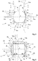
- Fig. 1 shows a known from the prior art division of untrimmed long timber raw wood 1 with a forest edge 2 and a longitudinal axis 3.
- the long timber raw wood 1 has a raw wood length 4 and a raw wood outer surface 5.
- four side boards 40 are separated from the long wood raw timber 1, leaving a central square timber 60 with a substantially square cross-section and is available for other applications.
- Fig. 1 can be removed, in this conventional division process disadvantageously high material losses are accepted in order to work out the side boards 40 of the full timber long timber 1. These material losses can at best be processed into heating pellets and recycled.
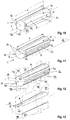
- the pictures Fig. 2 to Fig. 5 each show an unedged longwood raw wood trunk 1 in a sequence of individual processing steps of the manufacturing method according to the invention.
- Fig. 2 illustrated in a first step by a chip-removing device 100 in pairs opposing guide surfaces 11 and 12 or 13 and 14, which guide surfaces each have the same or different guide surface widths 15.
- the guide surfaces 11 to 14 serve to guide and as a support for the subsequent processing steps.
- long timber raw timber 1 it is provided within the scope of the invention, if necessary, to provide only two diametrically opposite guide surfaces on long timber raw timber 1. If, for example, plank, board or squared timber is used as long wood raw timber 1, which already has suitable planar guide surfaces as support for the subsequent processing steps, then this first processing step may also be omitted.
- relief grooves 20 with a relief groove depth 21 and a relief groove width 22 of a cutting or milling device 200 are shown on the provided with guide surfaces 11 to 14 long wood raw timber 1 relief grooves.
- the relief grooves 20 are here in a dash-dotted line of symmetry 17 of arranged two diametrically opposite guide surfaces 11 and 12 respectively. It is also conceivable, in a further processing step, to arrange relief grooves 20 in a dash-dotted plane of symmetry 18 of the two opposing guide surfaces 13 and 14.
- the long wood raw wood 1 is rotated about its longitudinal axis 3 by a rotation angle of 90 °.
- profiles 30 are arranged on edge sections 16 of each guide surface 11 to 14 by a mold-cutting device 300.
- An adjustment angle 31 of the shape-cutting device 300 can be adapted to the radius of curvature of the forest edge 2, can be seen on the profiles 30 and is for example between 20 ° and 66 °.
- the production of the profilings 30 takes place here essentially simultaneously with the production of the relief grooves 20.
- the shape-cutting device 300 has in each case two butt chamfers 32, which are provided on the two edges of the profiling 30.
- the Stoßfasen 32 serve that such profiled side boards 40 can be precisely adjusted during subsequent bonding to the profiles 30 and also do not slip each other during the transmission of lateral pressure during bonding.
- one or more butt chamfers 32 may be arranged in the region of the oblique profiles 30.
- FIG. 5 drawn after removal of the two side boards 40 of the central timber beam 60 more side boards 40, 41 along cutting planes 46, 47 or other long wood parts 70 - shown in broken lines - are separated along cutting planes 72.
- Fig. 5 further clarifies in a comparison, the increased yield of the manufacturing method according to the invention in comparison to that in Fig. 1 shown division pattern.
- the contours of in Fig. 1 shown side boards 40 are in Fig. 5 outlined in phantom in order to be able to contrast the yield increase of the side board cross sections 40, 41 obtained by the novel division method.
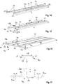
- FIG. 6 to FIG. 9 each show a long wood raw log 1 in a sequence of individual processing steps of the manufacturing method according to the invention, wherein a cutting guide in Fig. 7 for the division of the long wood raw timber 1 along cutting planes 46 takes place, which are arranged substantially parallel to the longitudinal axis direction 3 of the long wood raw timber 1.
- the two side boards 40 are here separated at opposite guide surfaces 11, 12.
- guide surfaces 11, 12 are obtained which have different guide surface widths 15, 15 'and 15 "over the raw wood length 4.
- a side board width 43 of the side boards 40 is - as well as the guide surface width 15 - also on the taper of the processed long logs raw timber 1 dependent and can be between a narrower side board 43 'at a tapered side board end and a relation to the middle side board width 43 enlarged side board width 43 "on
- the side boards 40 are dried after separation from the long timber raw wood 1.
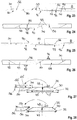
- the other pictures 10 to FIG. 13 show in each case a longwood raw wood trunk 1 in a sequence of individual processing steps of the production method according to the invention, the cutting guide for dividing the long wood raw wood here along cutting planes 77, 78 takes place which substantially parallel to tangent planes 75, 76 to a shell outer surface 5 of Langholz- Raw wood 1 are arranged.
- This version with mantelparallelen processing steps is particularly suitable for the recovery of untrimmed long timber raw wood 1 with a tapered over its raw wood length 4 perimeter or diameter.
- FIGS. 14 to 16 Each separated side boards represent 40 in a sequence of processing steps to obtain a lumber panel 90 according to the manufacturing method of the invention.
- Fig. 14 shows two side boards 40 after drying that are not split lengthwise.
- the two side boards 40 of the same long wood raw timber trunk 1 are sorted in pairs and placed by mutual rotation by 180 ° and Spend in toppled layers suitable to each other, as in Fig. 15 is shown.
- the side boards 40 are coated in the longitudinal direction 44 along their edges 30 provided with profiles edge portions 16, which now form butt joints 30, with adhesive 80 and bonded together under lateral pressure, preferably with additional surface pressure.
- a single-ply lumber panel 90 having a lumber panel width 91 and a lumber panel length 92 is obtained.
- the sawn timber plate length 92 essentially corresponds to the raw timber length 4.
- the sawn timber plate 90 can, if necessary, be trimmed at its edges.
- the relief groove 20 has a relief groove depth 21 of less than 50%, preferably less than 40%, of the material thickness 42 of a side board 40.
- the relief groove 20 has a relief groove width 22, for example, of 3 mm.
- Fig. 17 shows in a side view the processing of a long wood part 70, for example a Brettholzteils 70, in the context of the manufacturing method according to the invention.
- the term long timber raw wood 1 also means at least partially unedged screed, board and / or squared timber.
- the Brettholzteil 70 are no guide surfaces available, so here with known centering such as Scherenzentriervorraumen a Besaumautomaten the Brettholzteil 70 centered on the tree edges 2 and preferably measured and the best possible positions for the profiles 30 at the two edge portions 16 of the Brettholzteils 70 and a relief groove 20 are determined substantially in the middle of the board.
- the profiled side board is dried and can then also be processed to a lumber plate 90.
- FIG. 18 to FIG. 22 show each separated side board parts 50 in a sequence of processing steps to obtain a further variant of a sawn timber plate 90 according to the manufacturing method of the invention.
- already dried side board 40 this guided along its profiling 30, if necessary, positively centered and nachprofiliert, in order to be able to be guided particularly accurately to the nachprofil faced profile surfaces and divided along a dividing section surface 56 by means of a dividing device 500.
- the division cut surface 56 extends in a central side board symmetry plane 48, in which substantially also the relief groove 20 is located.
- the relief groove 20 serves in a further parts of the side board 40 in two side board parts 50 at the same time as a guide or orientation of the dividing device 500, for example a circular saw.
- the nachprofiled profile surfaces can serve as adhesive surfaces for the subsequent bonding of the board parts as a result and without additional, further processing step already.
- Fig. 19 the two side board parts 50 are already shown divided along the dividing cut surface 56.
- Analogous to the pictures FIGS. 14 to 16 are also shown here in the pictures FIGS. 19 to 22 the two side board parts 50 suitably arranged side by side by twisting by 180 ° and / or moving into fallen layers, coated with adhesive 80 to the adjacent profiles 30 and the division cut surfaces 56 and under lateral pressure and preferably with surface pressure together to a lumber panel 90 glued.
- undivided side boards 40, 41 as well as divided side board parts 50, 51 can be adhesively bonded together to form a sawn timber plate 90.
- Fig. 23 shows a side view of a sawn timber plate 90 with side board parts 50, which are each placed alternately in neutral annual ring layer 95, 96 together and glued together.
- Fig. 24 shows in an enlarged view the in Fig. 23 marked section A.
- a lumber plate 90 is produced with a particularly advantageous structure.
- the side board parts 50 are each here in pairs alternately at the oblique joints 30 in neutral annual ring position 95 and the straight pitch-cut surfaces 56 also in neutral annual ring layer 96 laid together glued together 80. At the glued together oblique joints 30 extend the oblique Profileings thus substantially tangentially to the annual rings 95 of the side boards or side board parts 50.
- each division-cut surfaces 56 are glued together meet the annual ring layers 96 of the two joining partners each at a substantially right angle to the division -Cutting surfaces 56 and on the impact surface, wherein the neutral annual ring curves 96 extend in opposite directions in opposite directions. Due to the harmonic arrangement always pairwise associated board partner 50, which are adjacent here either alternately at their butt joints 30, or their division-sectional surfaces 56 adjacent or glued together, a uniform wave-shaped, neutral course of the annual ring layers 95, 96 on the sawn timber 90th scored and warping the finished lumber panel 90 largely avoided.
- Fig. 25 illustrates a front side of a lumber plate 90 with side board parts 50, which was deviated at a joint 97 of the neutral annual ring position and at this a joint 97 adversely adjacent side board parts 50 with an annual ring course without neutral annual ring layer are placed together and glued together.
- Fig. 26 shows in an enlarged view the in Fig. 25 marked section B.
- this lumber plate 90 will at least disadvantageously at least buckle at the joint 97 without neutral annual ring position or cracks will form on the bonded division cut surface 56 in the region of the joint 97, which leads to a weakening of the lumber plate 90.
- the other connection points, in which the side board parts 50 are connected to each other in neutral annual ring position, are referred to as joints 96.
- Fig. 27 shows an end face of a conically profiled side board 40 in front of the substantially central parts along the sobrettsymmetrieebene 48 and the subsequent arrangement of the two sobrettmaschine 50 in a pairwise corresponding or mutually rotated by 180 ° and fallen position.
- the middle side board width 43 varies between a smaller side board width 43 'at the tapered side board end and an enlarged side board width 43 "at the opposite longitudinal end 44 in the longitudinal direction
- Side boards 40 Likewise, then after dividing the divided side board parts 50 in the longitudinal direction 54 each have different widths 53, 53 'and 53 "on.
- Fig. 28 shows similar to Fig. 27 also a front side of a side board 40, but this side board 40 is profiled here in parallel.
- the undivided side board 40 has a lateral board width 43 that is substantially the same in the longitudinal direction 44.
- the divided side board parts 50 in the longitudinal direction 54 each have substantially equal widths 53.
Landscapes
- Engineering & Computer Science (AREA)
- Life Sciences & Earth Sciences (AREA)
- Wood Science & Technology (AREA)
- Forests & Forestry (AREA)
- Manufacturing & Machinery (AREA)
- Mechanical Engineering (AREA)
- Architecture (AREA)
- Civil Engineering (AREA)
- Structural Engineering (AREA)
Description
Die Erfindung betrifft ein Verfahren zur Herstellung einer Schnittholzplatte aus Langholz-Rohholz. Weiters werden von der Erfindung Schnittholzplattenprodukte, welche gemäß dem erfindungsgemäßen Herstellungsverfahren hergestellt sind, angegeben.The invention relates to a method for producing a lumber panel from long wood raw wood. Furthermore, the invention relates to sawn timber products which are produced according to the production process according to the invention.
Aus dem Stand der Technik sind unterschiedliche Ausführungen von Verfahren zur Herstellung von Schnittholzplatten bekannt. Dokument
Weiters ist aus Dokument
Dokument
Zusätzlich zu den bereits vorgenannten Nachteilen ist an diesen Verfahren zumindest nachteilig, dass ein Profilieren von inneren Teilen bzw. von Einzelelementen nach dem Trocknen aufwendig ist, weshalb bei diesen Verfahren keine hohen Durchsatzleistungen erreicht werden können. Beispielsweise können mit derzeitigen Bearbeitungsmaschinen maximal 25 innere Brett- und/oder Bohlenteile pro Minute profiliert werden.In addition to the disadvantages already mentioned above, it is at least disadvantageous in these methods that profiling of internal parts or of individual elements after drying is complicated, which is why high throughput rates can not be achieved with these methods. For example, with current processing machines a maximum of 25 inner board and / or screed parts per minute can be profiled.
Es ist somit die Aufgabe der vorliegenden Erfindung ein verbessertes Verfahren zur Herstellung von Schnittholzplatten aus Seitenbrettware bereitzustellen, das die geschilderten Nachteile des Standes der Technik vermeidet, und mit welchem möglichst verlustfrei bei gleichzeitig hoher Durchsatzleistung Seitenbretter mit für die Festigkeit günstigem, spannungsfreiem, insbesondere rissfreiem, Faserverlauf sowie möglichst ohne Verwölbungen erhalten werden.It is therefore the object of the present invention to provide an improved method for the production of lumber boards from Seitenbrettware, which avoids the disadvantages of the prior art, and with which loss as possible with high throughput side boards with strength for the sake of strength, stress-free, especially crack-free, Fiber course as well as possible without warping be obtained.
Diese Aufgabe wird bei einem Herstellungsverfahren gemäß Anspruch 1 gelöst. Vorteilhafte Ausgestaltungen und Fortbildungen der Erfindung sind in den Unteransprüchen und der Beschreibung dargelegt.This object is achieved in a manufacturing method according to
Das erfindungsgemäße Verfahren zur Herstellung von Schnittholzplatten aus Langholz-Rohholz umfasst die folgenden Herstellungsschritte:
- a. Herstellen von Profilierungen mithilfe einer Formschneidenden Vorrichtung jeweils an Randabschnitten von zumindest zwei gegenüberliegenden Führungsflächen, welche an eine Waldkante des zumindest teilweise unbesäumten Langholz-Rohholzes angrenzen, wobei die Profilierungen an den Randabschnitten einer Führungsfläche vorzugsweise symmetrisch zu einer Führungsflächensymmetrieebene angeordnet sind, welche Führungsflächensymmetrieebene im Wesentlichen senkrecht zu den gegenüberliegenden Führungsflächen sowie im Wesentlichen mittig der jeweiligen Führungsflächenbreiten gerichtet ist;
- b. Herstellen von zumindest einer Entlastungsnut mithilfe einer Einschnitt- oder Fräsvorrichtung an zumindest zwei gegenüberliegenden Führungsflächen, wobei die zumindest eine Entlastungsnut jeweils im Wesentlichen senkrecht zur Führungsfläche angeordnet ist;
- c. Abtrennen von zumindest zwei Seitenbrettern an diametral gegenüberliegenden Führungsflächen mithilfe einer Schneidvorrichtung entlang von Schnittebenen jeweils in Längsrichtung des Langholz-Rohholzes unter Bildung einer zentralen Kantholzbohle;
- d. Gegebenenfalls Abtrennen weiterer Seitenbretter und/oder Langholzteile jeweils in Längsrichtung des Langholz-Rohholzes von der zentralen Kantholzbohle;
- e. Gegebenenfalls Anordnen und/oder Stapeln der Seitenbretter jeweils in eine paarweise miteinander korrespondierende sowie gegenseitig um 180° gedrehte und/oder gestürzte Lage;
- f. anschließendes Trocknen der Seitenbretter durch Lagerung in verdunstungsfördernder Umgebung;
- g. vorzugsweise Egalisieren und/oder Nachprofilieren der Profilierungen der getrockneten Seitenbretter;
- h. vorzugsweise Teilen der getrockneten Seitenbretter in Seitenbrettteile durch Anbringen einer im Wesentlichen in einer mittigen Seitenbrettsymmetrieebene des Seitenbretts verlaufenden Teilungs-Schnittfläche mittels einer Teilungsvorrichtung;
- i. Sortieren der getrockneten Seitenbretter und/oder Seitenbrettteile, wobei ungeteilte Seitenbretter insbesondere durch gegenseitiges Verdrehen um 180° und/oder Verbringen in gestürzte Lagen geeignet nebeneinander angeordnet werden, sodass jeweils ihre Seitenbrettsymmetrieebenen im Wesentlichen parallel zueinander zu liegen kommen, und/oder bereits geteilte, paarweise miteinander korrespondierende Seitenbrettteile derart nebeneinander angeordnet werden, dass ihre Teilungs-Schnittflächen im Wesentlichen parallel zueinander zu liegen kommen;
- j. Auftragen von Klebemittel an mit Profilierungen versehenen Randabschnitten passend profilierter Seitenbretter und/oder passender Seitenbrettteile und/oder an Teilungs-Schnittflächen der Seitenbrettteile;
- k. Verkleben der mit Klebemittel versehenen profilierten Randabschnitte und/oder Teilungs-Schnittflächen von seitlich nebeneinander angelegten Seitenbrettern und/oder Seitenbrettteilen unter Druck, vorzugsweise unter seitlichem Druck gegen die mit Klebemittel versehenen Flächen, zu einer Schnittholzplatte mit einer Schnittholzplattenbreite, wobei eine Schnittholzplattenlänge im Wesentlichen einer Rohholzlänge entspricht;
- l. Gegebenenfalls Beschneiden der gesamten Schnittholzplatte an deren Längsseitenrändern in Längsrichtung der verleimten Seitenbretter und/oder der Seitenbrettteile auf eine gewählte Schnittholzplattenbreite und/oder Beschneiden an Stirnflächen der verleimten Seitenbretter und/oder der Seitenbrettteile quer zu deren Längsrichtung auf eine gewählte Schnittholzplattenlänge mithilfe zumindest einer Schneidvorrichtung.
- a. Producing profilings by means of a shape-cutting device in each case at edge portions of at least two opposite guide surfaces which adjoin a forest edge of the at least partially unedged longwood raw wood, wherein the profilings are arranged on the edge portions of a guide surface preferably symmetrical to a Führungsflächensymmetrieebene, which Führungsflächensymmetrieebene substantially perpendicular is directed to the opposite guide surfaces and substantially centrally of the respective guide surface widths;
- b. Producing at least one relief groove by means of a cutting or milling device on at least two opposite guide surfaces, wherein the at least one relief groove is arranged in each case substantially perpendicular to the guide surface;
- c. Separating at least two side boards on diametrically opposite guide surfaces by means of a cutting device along cutting planes, respectively in the longitudinal direction of the long timber raw wood, to form a central timber beam;
- d. Optionally, separating further side boards and / or long wood parts in each case in the longitudinal direction of the long wood raw wood from the central timber beam;
- e. Optionally, arranging and / or stacking the side boards each in a pairwise mutually corresponding and mutually rotated by 180 ° and / or fallen position;
- f. subsequent drying of the side boards by storage in evaporative environment;
- G. preferably equalizing and / or reprofiling the profiles of the dried side boards;
- H. preferably dividing the dried side boards into side board parts by attaching a partition cut surface extending substantially in a central side board symmetry plane of the side board by means of a partitioning device;
- i. Sorting the dried side boards and / or side board parts, wherein undivided side boards, in particular by mutual rotation by 180 ° and / or placement in toppled layers are arranged side by side, so that each Seitenbrettsymmetrieebenen come to lie substantially parallel to each other, and / or already divided, in pairs mutually corresponding side board parts are arranged side by side in such a way that their dividing cut surfaces come to lie substantially parallel to one another;
- j. Applying adhesive to profiled edge portions of profiled side boards and / or matching side board parts and / or to split cut surfaces of the side board parts;
- k. Adhering the adhesive profiled edge portions and / or pitch surfaces of laterally adjacent side boards and / or side board members under pressure, preferably under lateral pressure against the adhesive surfaces, to a lumber panel having a lumber panel width, wherein a lumber panel length is substantially one lumber length corresponds;
- l. Optionally, trimming the entire lumber panel at its longitudinal side edges in the longitudinal direction of the glued side boards and / or the side board parts on a selected Sawn wood panel width and / or trimming on end faces of the glued side boards and / or the Seitenbrettteile transverse to the Lengthwise to a selected lumber plate length using at least one cutting device.
Unter dem Begriff Langholz-Rohholz werden im Weiteren sowohl zumindest teilweise unbesäumte Holzstämme, als auch zumindest teilweise unbesäumtes Bohlen-, Brett- und/oder Kantholz verstanden. Je nach Vorbearbeitung des Rohholzes kann es erforderlich sein, zumindest zwei diametral gegenüberliegende Führungsflächen an den mit Waldkanten bedeckten Außenflächen des unbesäumten Langholz-Rohholzes auszubilden, um die weitere Bearbeitung überhaupt erst zu ermöglichen. Ebenso kann es beim Einsatz von Brett- oder Kantholz erforderlich sein, entsprechende Führungsflächen als Auflageflächen für die nachfolgenden Herstellungsschritte mittels geeigneter, Span abhebender Vorrichtungen nachzuarbeiten. Der in der Mitte des Langholz-Rohholzes nach dem Abtrennen von Seitenbrettern und/oder von weiteren Langholzteilen verbleibende prismatische oder im Wesentlichen keilförmige Langholzteil wird hier jeweils als zentrale Kantholzbohle bezeichnet.The term long timber raw wood is understood to mean both at least partially untrimmed logs, as well as at least partially untrimmed planks, boards and / or squared timber. Depending on the pre-processing of the raw wood, it may be necessary to form at least two diametrically opposite guide surfaces on the forested edges covered with outer surfaces of the unedged long wood raw wood to allow further processing in the first place. Likewise, when using board or square timber, it may be necessary to rework corresponding guide surfaces as bearing surfaces for the subsequent production steps by means of suitable devices which lift off the chip. The prismatic or essentially wedge-shaped long wood part remaining in the middle of the long wood raw wood after the separation of side boards and / or other long wood parts is referred to here in each case as the central timber beam.
Vorteilhaft werden im weiteren Herstellungsverfahren durch das Herstellen von Profilierungen sowie das Anbringen einer oder mehrerer Entlastungsnuten an den Führungsflächen bereits im frischen Zustand des Holzes - also noch vor dem Trocknen - die Langholzteile bzw. Seitenbretter im Wesentlichen spannungsfrei gemacht und es wird somit ein Aufwölben oder Verdrehen der Langholzteile während des nachfolgenden Trocknens verhindert.Advantageously, in the further manufacturing process by the production of profilings and the attachment of one or more relief grooves on the guide surfaces already in the fresh state of the wood - ie even before drying - made the Langholzteile or side boards substantially stress-free and it is thus a bulging or twisting prevents the long wood parts during subsequent drying.
Dieses Herstellungsverfahren ist besonders wirtschaftlich, da das Profilieren an den Randabschnitten der späteren Seitenbretter sowie das Anordnen der Entlastungsnuten zu einem Zeitpunkt erfolgt, an dem die späteren Seitenbretter noch mit der späteren zentralen Kantholzbohle verbunden sind. Durch die besonders günstige Anordnung der Seitenbretter in randnaher Lage bzw. direkt angrenzend an die Waldkante eines unbesäumten Holzstammes kann die Ausbeute des erfindungsgemäßen Herstellungsverfahrens im Vergleich zum bisherigen Stand der Technik deutlich erhöht und das Ausgangsholz deutlich besser ausgenutzt werden. Durch die Vorprofilierung von Führungsflächen in Baumkantennähe bzw. angrenzend an eine Waldkante wird die nachfolgende Bearbeitung wesentlich erleichtert und die anschließenden Verfahrensschritte können besonders rasch und wirtschaftlich durchgeführt werden.This manufacturing method is particularly economical, since the profiling takes place at the edge portions of the later side boards and arranging the relief grooves at a time at which the later side boards are still connected to the later central timber beam. Due to the particularly favorable arrangement of the side boards in near-edge location or directly adjacent to the forest edge of an unedged timber trunk, the yield of the manufacturing method according to the invention can be significantly increased compared to the prior art and the starting wood can be exploited significantly better. Due to the pre-profiling of guide surfaces in the vicinity of the tree edge or adjacent to a forest edge, the subsequent processing is substantially facilitated and the subsequent method steps can be carried out particularly quickly and economically.
Vorzugsweise werden die getrockneten Seitenbretter nach dem Trocknungsschritt egalisiert, und/oder an den Profilierungen nachprofiliert. Beim Egalisieren liegen die Seitenbretter bzw.Preferably, the dried side boards are leveled after the drying step, and / or profiled on the profiles. When leveling lie the side boards or
Langholzteile mit einer der Schnittflächen auf einem planen Untergrund auf oder werden über diesen geführt, um gegebenenfalls durch Materialabtragung an zumindest einer Schnittfläche bis zu einer vorgegebenen Materialstärke bearbeitet zu werden. Durch das Nachprofilieren der Profilierungen wird zumindest eine Profilierung bzw. eine Stoßfuge des Seitenbretts für eine anschließende Zwangsführung bzw. Zwangszentrierung vorbereitet. Das nachprofilierte Seitenbrett kann somit in den weiteren nachfolgenden Bearbeitungsschritten besonders exakt entlang der Profilierungen geführt werden. Weiters dient das Nachprofilieren der getrockneten Seitenbretter auch dazu, die eingangs vorprofilierten Randabschnitte nun durch das scharfkantige Nachprofilieren bereits als fertige Klebeflächen für das nachfolgende Verkleben der Seitenbretter bzw. der Seitenbrettteile vorzubereiten. Beispielsweise können beim Nachprofilieren noch eine oder mehrere Stoßfasen an den Führungsflächen profiliert werden, wodurch das Führen entlang der Profilierungen sowie das nachfolgende Verkleben besonders exakt erfolgen können. Ein Materialabtrag durch das Nachbearbeiten bzw. Nachprofilieren der bereits früher vorprofilierten Randabschnitte ist dabei minimal und beträgt beispielsweise nur wenige mm Materialabtrag.Langholzteile with one of the cut surfaces on a flat surface or are guided over this, if necessary to be processed by material removal on at least one cut surface to a predetermined thickness. By profiling the profiles at least one profiling or a butt joint of the side board is prepared for a subsequent forced operation or forced centering. The nachprofiled side board can thus be performed particularly accurately along the profiles in the subsequent subsequent processing steps. Furthermore, the re-profiling of the dried side boards also serves to prepare the initially profiled edge sections by the sharp-edged reprofiling already as finished adhesive surfaces for the subsequent gluing of the side boards or the side board parts. For example, one or more bumps can be profiled on the guide surfaces during re-profiling, whereby the guiding along the profiles and the subsequent bonding can be done very accurately. A material removal by the reworking or reprofiling of the previously pre-profiled edge portions is minimal and amounts to, for example, only a few mm material removal.
Zweckmäßig werden bei einem erfindungsgemäßen Verfahren eingangs vor dem Herstellen der Profilierungen zumindest zwei diametral gegenüberliegende Führungsflächen an einer Waldkante des unbesäumten Langholz-Rohholzes mithilfe einer Span abhebenden Vorrichtung ausgebildet, wobei einander gegenüberliegende Führungsflächen jeweils in Längsrichtung des Langholz-Rohholzes angeordnet sind sowie eine Führungsflächenbreite aufweisen. Mit den Führungsflächen, die an einander gegenüberliegenden Längsseiten an der Waldkante des unbesäumten Langholz-Rohholzes angeordnet werden, kann die weitere Verarbeitung des Langholz-Rohholzes wesentlich vereinfacht werden. Für die nachfolgenden Bearbeitungsschritte, beispielsweise das Herstellen von Profilierungen und das Anbringen von Entlastungsnuten, stehen bereits die Führungsflächen als im Wesentlichen plane Auflageflächen zur Verfügung.Appropriately, in a method according to the invention, at least two diametrically opposite guide surfaces are formed on a forest edge of the unedged longwood raw wood by means of a chip removing device in a method according to the invention, wherein opposing guide surfaces are each arranged in the longitudinal direction of the long wood raw wood and have a guide surface width. With the guide surfaces, which are arranged on opposite longitudinal sides at the forest edge of the unedged long wood raw timber, the further processing of the long timber raw wood can be substantially simplified. For the subsequent processing steps, for example the production of profiles and the attachment of relief grooves, the guide surfaces are already available as essentially planar bearing surfaces.
Besonders vorteilhaft ist bei einem erfindungsgemäßen Verfahren, dass eine Entlastungsnut im Wesentlichen mittig in der Führungsflächensymmetrieebene der Führungsfläche angeordnet ist. In dieser Ausführung wird eine Entlastungsnut im Wesentlichen mittig der Führungsfläche angeordnet. Da die Führungsfläche im Wesentlichen eine spätere Seitenfläche eines der Seitenbretter bildet, befindet sich die Entlastungsnut somit auch im Wesentlichen mittig der Seitenfläche des später von der zentralen Kantholzbohle abzutrennenden Seitenbretts.In a method according to the invention, it is particularly advantageous that a relief groove is arranged substantially centrally in the guide surface symmetry plane of the guide surface. In this embodiment, a relief groove is arranged substantially centrally of the guide surface. Since the guide surface essentially forms a later side surface of one of the side boards, the relief groove is thus also located substantially in the center of the side surface of the side board to be separated later from the central timber board.
Besonders zweckmäßig weist bei einem erfindungsgemäßen Verfahren die zumindest eine Entlastungsnut eine Entlastungsnuttiefe von kleiner 50%, vorzugsweise von kleiner 40%, einer Materialstärke eines Seitenbretts auf. Vorteilhaft wird durch Auswahl derartiger Entlastungsnuttiefen in Bezug zur Materialstärke des Seitenbretts einerseits ein effizienter Spannungsabbau in den Seitenbrettern ermöglicht und ein Verwölben oder Verwinden bzw. eine Rissbildung des Seitenbretts insbesondere während des Trocknens weitestgehend vermieden. Andererseits werden die Seitenbretter durch das Anbringen der Entlastungsnuten mit Entlastungsnuttiefen kleiner die halbe Materialstärke nicht nachteilig in ihrer mechanischen Festigkeit bzw. Steifigkeit geschwächt.In a method according to the invention, the at least one relief groove particularly expediently has a relief groove depth of less than 50%, preferably of less than 40%, of a material thickness of a side board. Advantageously, by selecting such relief groove depths in relation to the material thickness of the side board, on the one hand, efficient stress relief in the side boards is made possible and warping or twisting or cracking of the side board, in particular during drying, is largely avoided. On the other hand, by attaching the relief grooves with relief groove depths smaller than half the material thickness, the side boards are not adversely affected in their mechanical strength or rigidity.
In einer bevorzugten Weiterbildung der Erfindung wird bei einem Verfahren zur Herstellung von Schnittholzplatten nach dem Abtrennen von zumindest zwei Seitenbrettern an diametral gegenüberliegenden Führungsflächen die zentrale Kantholzbohle um ihre Längsachse um einen Drehwinkel von 90° gedreht und es werden zwei weitere diametral gegenüberliegende Führungsflächen seitlich an der zentralen Kantholzbohle angeordnet, wobei die einander gegenüberliegenden weiteren Führungsflächen jeweils in Längsrichtung der zentralen Kantholzbohle angeordnet sind sowie eine Führungsflächenbreite aufweisen, wobei weiters Profilierungen an den Randabschnitten der zwei gegenüberliegenden Führungsflächen hergestellt werden und die Profilierungen an den Randabschnitten vorzugsweise symmetrisch zu einer Führungsflächensymmetrieebene, welche im Wesentlichen senkrecht zu den gegenüberliegenden Führungsflächen sowie im Wesentlichen mittig der jeweiligen Führungsflächenbreiten gerichtet ist, angeordnet sind, sowie mindestens eine Entlastungsnut, die jeweils im Wesentlichen senkrecht zur Führungsfläche angeordnet ist, an den Führungsflächen hergestellt wird, worauf zwei weitere Seitenbretter an den diametral gegenüberliegenden Führungsflächen entlang von Schnittebenen jeweils in Längsrichtung des Langholz-Rohholzes von der zentralen Kantholzbohle abgetrennt werden. In dieser Ausführung werden besonders zweckmäßig an vier Seiten, die jeweils um die Längsachse um einen Drehwinkel von 90° zueinander verdreht angeordnet sind, Führungsflächen angeordnet, diese an Randabschnitten profiliert und mit jeweils zumindest einer Entlastungsnut versehen. In weiterer Folge können nacheinander jeweils zwei gegenüberliegende Seitenbretter, in Summe also bis zu vier Seitenbretter, von der zentralen Kantholzbohle abgetrennt werden. Durch geeignete Wahl der Profilierungen gelingt es in dieser Ausführung des erfindungsgemäßen Herstellungsverfahrens, mit minimalen Verlusten und größtmöglicher Ausbeute Seitenbrettware von der zentralen Kantholzbohle abzutrennen. Die zentrale Kantholzbohle steht danach für weitere Verwendungsmöglichkeiten zur Verfügung.In a preferred embodiment of the invention, in a method for producing lumber panels after separating at least two side boards on diametrically opposed guide surfaces, the central timber board is rotated about its longitudinal axis by a rotation angle of 90 ° and there are two more diametrically opposed guide surfaces laterally to the central Scaled timber plank arranged, wherein the opposing further guide surfaces are each arranged in the longitudinal direction of the central timber screed and have a guide surface width, further profilings are made at the edge portions of the two opposite guide surfaces and the profilings at the edge portions preferably symmetrical to a Führungsflächensymmetrieebene, which is substantially perpendicular is directed to the opposite guide surfaces and substantially centrally of the respective guide surface widths are arranged, as well as at least one relief groove, which is respectively arranged substantially perpendicular to the guide surface is made on the guide surfaces, whereupon two more side boards are separated at the diametrically opposite guide surfaces along cutting planes each in the longitudinal direction of the long wood raw wood from the central timber beam , In this embodiment, guide surfaces are particularly expediently arranged on four sides, which are each rotated around the longitudinal axis by an angle of rotation of 90 °, profiled on edge sections and provided with at least one relief groove. Subsequently, two opposite side boards, in total up to four side boards, can be separated one after the other from the central square timber board. By a suitable choice of the profilings, it is possible in this embodiment of the manufacturing method according to the invention to separate side board ware from the central square timber plank with minimal losses and the greatest possible yield. The central scantling plank is then available for further uses.
Besonders vorteilhaft erfolgt bei einem Verfahren gemäß der Erfindung das Herstellen von Profilierungen jeweils an Randabschnitten der zumindest zwei gegenüberliegenden Führungsflächen sowie das Herstellen der Entlastungsnuten an zumindest zwei diametral gegenüberliegenden Führungsflächen im Wesentlichen gleichzeitig. In dieser Ausführung werden an den Führungsflächen die Profilierungen an deren Randabschnitten sowie die Entlastungsnuten im Wesentlichen gleichzeitig in einem Arbeitsschritt durchgeführt. Dadurch wird ein besonders effizientes, rasches Herstellungsverfahren für Schnittholzplatten ermöglicht. Die Entlastungsnut kann auch als Unterstützung für ein störungsfreies Abfördern bzw. Abtrennen der Seitenbretter von der verbleibenden Kantholzbohle dienen.In a method according to the invention, it is particularly advantageous to produce profilings at edge portions of the at least two opposite guide surfaces and to produce the relief grooves on at least two diametrically opposite guide surfaces substantially simultaneously. In this embodiment, the profiles at the edge portions and the relief grooves are performed substantially simultaneously in one step on the guide surfaces. This enables a particularly efficient, rapid production process for sawn timber panels. The relief groove can also serve as a support for trouble-free removal or separation of the side boards from the remaining square timber board.
Zweckmäßig wird bei einem Verfahren gemäß der Erfindung das Langholz-Rohholz vor der Bearbeitung und/oder vor dem Herstellen der Entlastungsnuten und/oder vor dem Herstellen der Profilierungen an den Randabschnitten und/oder vor dem Abtrennen der Seitenbretter und/oder gegebenenfalls vor dem Abtrennen weiterer Langholzteile von der zentralen Kantholzbohle von einer Vermessungseinrichtung vermessen. Mit Hilfe einer Vermessungseinrichtung können ein oder mehrere Verfahrensschritte des Herstellungsverfahrens vermessen werden und somit die Ausbeute des Verfahrens vorteilhaft weiter erhöht werden. Somit können auch Langholz-Rohholzteile, die beispielsweise einen gekrümmten Holzstamm oder Astgabelungen aufweisen, von der Vermessungseinrichtung erfasst und vermessen werden und Teilungsschnitte möglichst effizient an die individuelle Geometrie des jeweiligen Langholz-Rohholzteils angepasst werden.Appropriately, in a method according to the invention, the long wood raw wood prior to processing and / or prior to making the relief grooves and / or before making the profilings at the edge portions and / or before separating the side boards and / or optionally before separating another Measure logs of lumber from the central timber beam from a surveying facility. With the aid of a measuring device, one or more method steps of the production method can be measured, and thus the yield of the method can advantageously be further increased. Thus, long wood raw wood parts, which have, for example, a curved log or branching, can be detected and measured by the measuring device and division cuts are adapted as efficiently as possible to the individual geometry of the respective long wood raw wood part.
In einer bevorzugten Ausführung werden bei einem erfindungsgemäßen Verfahren die von der Vermessungseinrichtung erfassten Vermessungsdaten einer Steuerungseinrichtung zugeführt und von dieser zur Steuerung der Span abhebenden Vorrichtung und/oder der Einschnitt- oder Fräsvorrichtung und/oder der Formschneidenden Vorrichtung und/oder von Schneidvorrichtungen und/oder der Teilungsvorrichtung verwendet. Im Rahmen der Erfindung können die von der Vermessungseinrichtung erfassten Vermessungsdaten von der Steuerungseinrichtung zur Steuerung unterschiedlicher Vorrichtungen verwendet werden. Somit lassen sich die entsprechenden Vorrichtungen an die individuellen Erfordernisse beim Schneiden, Profilieren, Fräsen und/oder Teilen von Langholz-Rohholz bzw. von den Seitenbrettern anpassen.In a preferred embodiment, in a method according to the invention, the survey data acquired by the surveying device are fed to a control device and controlled by it for controlling the chip removing device and / or the cutting or milling device and / or the die cutting device and / or cutting devices and / or Dividing device used. In the context of the invention, the survey data acquired by the surveying device can be used by the control device to control different devices. Thus, the corresponding devices can be adapted to the individual requirements when cutting, profiling, milling and / or parts of longwood raw wood or from the side boards.
Zweckmäßig sind bei einem Verfahren gemäß der Erfindung einander gegenüberliegende Führungsflächen im Wesentlichen jeweils parallel zueinander sowie im Wesentlichen parallel zur Längsachse des Langholz-Rohholzes angeordnet sowie erfolgt eine Schnittführung zur Teilung von Langholz-Rohholz in Seitenbretter und/oder in Langholzteile entlang von Schnittebenen, welche im Wesentlichen parallel zur Längsachsenrichtung des Rohholzes sind. In dieser Ausführung des erfindungsgemäßen Herstellungsverfahrens sind die Führungsflächen bzw. die Schnittebenen zum Abtrennen von Seitenbrettern oder Langholzteilen jeweils im Wesentlichen parallel zur Längsachse des Langholz-Rohholzes angeordnet. Diese Ausführungsvariante mit achsparallelen Bearbeitungsschritten bietet sich für die Verwertung von unbesäumtem Langholz-Rohholz mit über seine Länge im Wesentlichen gleichem Umfang bzw. Durchmesser an. Abweichungen von einer im Wesentlichen zylindrischen Außenmantelform des Rohholzes werden in erster Linie von den Seitenbrettern aufgenommen. Die Seitenbrettbreite der Seitenbretter kann bei Wahl eines achsparallelen Zuschnitts an einem freien Ende etwa keilförmig oder konisch zulaufen und daher für die Weiterverarbeitung zu einer Schnittholzplatte nur bedingt geeignet sein. Die zentrale Kantholzbohle ist dafür besonders exakt im Wesentlichen rechtwinkelig beschnitten und kann für zahlreiche beliebige Anwendungen weiterverwendet werden.Appropriately, in a method according to the invention, opposing guide surfaces are arranged substantially parallel to each other and substantially parallel to the longitudinal axis of the long wood raw wood and takes place Cutting guide for the division of long wood raw wood in side boards and / or in long wood parts along cutting planes, which are substantially parallel to the longitudinal axis direction of the raw wood. In this embodiment of the manufacturing method according to the invention, the guide surfaces or the cutting planes for separating side boards or long wood parts are each arranged essentially parallel to the longitudinal axis of the long wood raw wood. This embodiment variant with axis-parallel processing steps lends itself to the utilization of untrimmed long wood raw timber with over its length substantially the same circumference or diameter. Deviations from a substantially cylindrical outer shell shape of the raw wood are absorbed primarily by the side boards. The side board width of the side boards can be approximately wedge-shaped or conical when selecting an axis-parallel blank at a free end and therefore be suitable for further processing to a lumber panel only conditionally. The central scantling board is trimmed for this purpose particularly precisely at right angles and can be reused for numerous other applications.
In weiteren vorteilhaften Ausführungsvarianten sind bei einem erfindungsgemäßen Verfahren einander gegenüberliegende Führungsflächen im Wesentlichen parallel zu einer von zwei diametral gegenüberliegenden Tangentialebenen an die konisch zulaufende Rohholzaußenfläche des Langholz-Rohholzes angeordnet, wobei erforderlichenfalls mit der Span abhebenden Vorrichtung von außen beginnend eine erste Führungsfläche parallel zur ersten Tangentialebene hergestellt wird, sowie eine weitere, der ersten Führungsfläche gegenüberliegende zweite Führungsfläche parallel zur zweiten Tangentialebene hergestellt wird und anschließend das Langholz-Rohholz mit einer Schnittführung entlang von Schnittebenen, welche wiederum im Wesentlichen parallel zu einer der zwei diametral gegenüberliegenden Tangentialebenen und/oder der gegenüberliegenden Führungsflächen sind, in Seitenbretter und/oder in Langholzteile entlang der Schnittebenen geteilt wird, wodurch eine sich verjüngende, keilförmige zentrale Kantholzbohle erhalten wird.In further advantageous embodiments, in a method according to the invention, opposing guide surfaces are arranged substantially parallel to one of two diametrically opposite tangential planes to the tapered raw wood outer surface of the longwood raw wood, starting with the chip removing device starting from the outside, if necessary, a first guide surface parallel to the first tangent plane and another, the first guide surface opposite second guide surface is made parallel to the second tangent plane and then the long wood raw wood with a cut along cutting planes, which in turn substantially parallel to one of the two diametrically opposite tangent planes and / or the opposite guide surfaces are divided into side boards and / or in longwood parts along the cutting planes, creating a tapered, wedge-shaped ige central timber screed is obtained.
In dieser Ausführung des erfindungsgemäßen Herstellungsverfahrens sind die Führungsflächen bzw. die Schnittebenen zum Abtrennen von Seitenbrettern oder Langholzteilen jeweils im Wesentlichen parallel zu einer von zwei Tangentialebenen an die äußere Mantelfläche des Langholz-Rohholzes angeordnet. Diese Ausführungsvariante mit mantelparallelen Bearbeitungsschritten bietet sich besonders für die Verwertung von unbesäumtem Langholz-Rohholz mit einem über seine Länge konisch zulaufenden Umfang bzw. Durchmesser an. Somit gelingt es durch mantelparallele Schnittführung, auch bei konisch zulaufenden Baumstämmen Seitenbrettware mit etwa konstanter Seitenbrettbreite zu gewinnen. Die Konizität des Holzstammes wird bei dieser Schnittführung weiter nach innen in die zentrale Kantholzbohle projiziert, welche dann eine im Wesentlichen keilförmige Kontur aufweist.In this embodiment of the manufacturing method according to the invention, the guide surfaces or the cutting planes for separating side boards or long wood parts are each arranged substantially parallel to one of two tangential planes on the outer surface of the long wood raw wood. This variant with mantelparallelen processing steps is particularly suitable for the utilization of untrimmed long wood raw wood with a tapered over its length circumference or diameter. Thus, parallelepiped cut management, even with conically tapered tree trunks, allows for side board goods with an approximately constant board width win. The conicity of the log is further projected in this cutting guide inwards into the central timber screed, which then has a substantially wedge-shaped contour.
In einer weiteren vorteilhaften Ausführung sind bei einem erfindungsgemäßen Verfahren für die Seitenbretter die Profilierungen in Form zweier zur Führungsflächensymmetrieebene im Wesentlichen symmetrischen schrägen ebenen Flächen ausgeführt, welche jeweils in einem Stellwinkel der Profilierungen möglichst umfangnahe zur Rohholzaußenfläche gewählt sind und die Profilierungen werden durch Span abhebende Werkzeuge, vorzugsweise durch Fräswerkzeuge, ziehende Stirnfräser oder durch rotierende Kreissägeblätter, unter Bildung zumindest einer Stoßfase hergestellt. In dieser Ausführung können durch Justieren der Stellwinkel der Span abhebenden Werkzeuge die Profilierungen besonders exakt an die jeweilige Geometrie des zu verwertenden Langholz-Rohholzes angepasst und somit Ausbeuteverluste vermieden werden. Der Stellwinkel wird je nach Beschaffenheit der Waldkante angepasst und es werden mit derartigen Werkzeugen profilierte Seitenbretter in hoher Qualität hergestellt. Durch zumindest eine kurze Stoßfase im Bereich jeder Profilierung wird bei Seitenbrettern, welche jeweils mit derartigen Profilierungen versehen sind, die exakte Justierung zum Verkleben sowie die Übertragung von Seitendruck während des Verklebens ermöglicht, ohne dass die beiden profilierten Seitenbretter beim Verkleben gegenseitig verrutschen. Wahlweise können eine oder mehrere Stoßfasen im Bereich der schrägen Profilierungen angeordnet sein. Die stufenförmigen Stoßfasen stehen dabei im Wesentlichen senkrecht auf die Schnittebenen.In a further advantageous embodiment, in the case of a method according to the invention for the side boards, the profilings are executed in the form of two oblique flat surfaces which are essentially symmetrical to the guide surface symmetry plane, which are each selected as close as possible to the raw wood outer surface in a setting angle of the profilings and the profilings are formed by tools that lift off the chip, preferably produced by milling tools, drawing end mills or by rotating circular saw blades, forming at least one shock chamfer. In this embodiment, the profiling can be adapted particularly precisely to the respective geometry of the raw timber to be utilized by adjusting the setting angle of the chip lifting tools and thus yield losses can be avoided. The adjustment angle is adjusted depending on the condition of the forest edge and it profiled side boards are made in such high quality with such tools. By means of at least a short bump in the area of each profiling, the exact adjustment for gluing and the transfer of lateral pressure during gluing is made possible for side boards, which are each provided with such profilings, without the two profiled side boards slipping during gluing. Optionally, one or more butt chamfers may be arranged in the region of the oblique profilings. The step-shaped bumps are essentially perpendicular to the cutting planes.
Zweckmäßig sind bei einer Schnittholzplatte, welche gemäß einer Variante des erfindungsgemäßen Verfahrens hergestellt ist, mehrere Seitenbretter und/oder Seitenbrettteile an ihren mit Profilierungen versehenen Randabschnitten und/oder an Teilungs-Schnittflächen zu einer einlagigen Verbundplatte verklebt. Besonders vorteilhaft werden Seitenbretter und/oder Seitenbrettteile, die nach dem erfindungsgemäßen Verfahren hergestellt sind, geeignet aneinander gelegt und mit Klebstoff miteinander zu einer einlagigen Verbundplatte verklebt. Um eine Schnittholzplatte mit gleichbleibender, hoher Qualität gewährleisten zu können, werden das Aneinanderlegen und/oder das Verkleben der Seitenbretter bzw. Seitenbrettteile entsprechend überwacht und kontrolliert.Suitably, in a lumber panel, which is produced according to a variant of the method according to the invention, a plurality of side boards and / or side board parts glued to their profiled edge portions and / or pitch-cut surfaces to form a single-layer composite panel. Particularly advantageous side panels and / or side panel parts, which are produced by the process according to the invention, suitably placed together and glued together with adhesive to form a single-layer composite panel. In order to ensure a lumber panel with consistent, high quality, the juxtaposition and / or bonding of the side boards or side board parts are monitored and controlled accordingly.
In einer Weiterbildung der Erfindung sind bei einer Schnittholzplatte Seitenbretter und/oder Seitenbrettteile mit im Wesentlichen gleicher Materialstärke miteinander verklebt. In dieser Ausführung wird vorteilhaft eine Schnittholzplatte mit im Wesentlichen gleicher Materialstärke erhalten, wodurch eine Nachbearbeitung durch Egalisieren der Schnittholzplatte entfallen kann.In one embodiment of the invention side boards and / or side board parts are glued together with a substantially equal thickness of material in a lumber panel. In this embodiment is advantageously a lumber panel with substantially the same Received material thickness, whereby post-processing can be omitted by equalizing the lumber panel.
Besonders vorteilhaft sind bei einer Schnittholzplatte Seitenbretter und/oder Seitenbrettteile mit im Wesentlichen konstanter Länge zu einer Schnittholzplattenbreite verbunden, wobei an Stirnflächen der Schnittholzplatte schräge Stoßfugen und/oder Teilungs-Schnittflächen und/oder stoßgefügte Seitenbretter mit symmetrischer Trapezform und/oder mit Entlastungsnuten ausgebildet sind. In dieser Ausführung können an den Stirnflächen der Schnittholzplatte noch die entsprechenden Stoßfugen und/oder Schnittflächen oder auch die Entlastungsnuten bei ungeteilten Seitenbrettern im Plattenquerschnitt festgestellt werden.Side boards and / or side board parts with a substantially constant length are particularly advantageously connected to a sawn timber plate width, with oblique butt joints and / or parting cut surfaces and / or side panels with symmetrical trapezoidal shape and / or relief grooves being formed on end faces of the sawn timber plate. In this embodiment, the corresponding butt joints and / or cut surfaces or even the relief grooves in undivided side boards in the plate cross-section can still be found on the end faces of the lumber panel.
In einer bevorzugten Weiterbildung der Erfindung sind bei einer Schnittholzplatte die Seitenbretter und/oder Seitenbrettteile jeweils paarweise alternierend an den schrägen Stoßfugen in neutraler Jahresringlage sowie an den geraden Teilungs-Schnittflächen ebenfalls in neutraler Jahresringlage aneinander gelegt sowie miteinander verklebt. Durch geeignetes, alternierendes Aneinanderlegen von paarweise geschnittenen Seitenbrettern und/oder paarweise geschnittenen Seitenbrettteilen und anschließendes Verkleben jeweils in neutraler Jahresringlage wird eine Schnittholzplatte mit einem besonders vorteilhaften Aufbau erzeugt. An den miteinander verklebten schrägen Stoßfugen verlaufen in neutraler Jahresringlage die schrägen Profilierungen somit im Wesentlichen tangential zu den Jahresringen der Seitenbretter. An den geraden Stoßstellen, an welchen jeweils Teilungs-Schnittflächen miteinander verklebt sind, treffen die Jahresringlagen der beiden Fügepartner jeweils unter einem im Wesentlichen rechten Winkel auf die Teilungs-Schnittflächen bzw. auf die Stoßfläche, wobei die Jahresringverläufe gegengleich in jeweils entgegengesetzte Richtungen weiter verlaufen. Durch die harmonische Anordnung immer paarweise zugehöriger Brettpartner wird ein gleichmäßig wellenförmiger Verlauf der Jahresringlage über die Schnittholzplatte erzielt und Verwölbungen der fertigen Schnittholzplatte weitestgehend vermieden.In a preferred embodiment of the invention, the side boards and / or side board parts are each pairwise alternately to the oblique joints in neutral annual ring position and the straight pitch cut surfaces also in neutral annual ring layer laid together and glued together in a lumber panel. By suitable, alternating juxtaposition of paired side boards and / or pairwise cut side board parts and subsequent bonding in each case in neutral annual ring position a sawn timber plate is produced with a particularly advantageous structure. The oblique profiles thus run essentially tangentially to the annual rings of the side boards in the neutral annual ring position on the oblique butt joints glued together. At the straight joints at which each division-cut surfaces are glued together, meet the annual ring positions of the two joining partners each at a substantially right angle to the division-cutting surfaces or on the abutment surface, the annual ring courses gegengleich run in opposite directions. Due to the harmonious arrangement always pairwise associated board partner a uniform wave-shaped course of the annual ring position is achieved on the sawn timber plate and warping the finished sawn timber plate largely avoided.
Vorteilhaft werden vor der Verklebung die Jahresringlagen der nebeneinander angelegten Brettpartner bzw. Fügepartner kontrolliert und erforderlichenfalls noch Seitenbretter und/oder Seitenbrettteile entsprechend neu ausgerichtet bzw. neu angelegt, um eine Verklebung der Schnittholzplatte an sämtlichen mit Profilierungen versehenen schrägen Stoßfugen bzw. an sämtlichen geraden Stoßstellen jeweils mit neutralen Jahresringlagen gewährleisten zu können. Durch die Kontrolle und Überwachung beim Aneinanderlegen der Seitenbretter und/oder Seitenbrettteile in neutraler Jahresringlage sowie beim Verkleben an den Stoßfugen und/oder den Teilungs-Schnittflächen können Schnittholzplatten mit gleichbleibend hoher Qualität hergestellt werden.Before the bonding, the annual ring layers of the adjacent board partners or join partners are advantageously checked and, if necessary, side boards and / or side board parts are reoriented or newly created, in order to bond the sawn board to all oblique butt joints provided with profilings or to all straight joints respectively to be able to guarantee with neutral annual rings. Through the control and monitoring when juxtaposing the side boards and / or side board parts in a neutral annual ring position as well as during gluing The butt joints and / or the division cut surfaces can be produced with consistently high quality lumber panels.
Weitere Einzelheiten, Merkmale und Vorteile der Erfindung ergeben sich aus der nachfolgenden Erläuterung von in den Zeichnungen schematisch dargestellten Ausführungsbeispielen. In den Zeichnungen zeigen:
-
Fig. 1 in einer Schnittansicht von der Seite einen Langholz-Rohholzstamm mit einem aus dem Stand der Technik bekannten Teilungsmuster zur Aufteilung von Seitenbrettware; -
Fig. 2 bis Fig. 5 jeweils einen Langholz-Rohholzstamm in seitlichen Schnittansichten in einer Abfolge einzelner Bearbeitungsschritte des erfindungsgemäßen Herstellungsverfahrens; -
Fig. 6 bis Fig. 9 jeweils einen Langholz-Rohholzstamm in seitlichen Schrägansichten in einer Abfolge einzelner Bearbeitungsschritte des erfindungsgemäßen Herstellungsverfahrens, wobei eine Schnittführung zur Teilung des Langholz-Rohholzes entlang von Schnittebenen erfolgt, welche im Wesentlichen parallel zur Längsachsenrichtung des Langholz-Rohholzes angeordnet sind; -
Fig. 10 bis Fig. 13 jeweils einen Langholz-Rohholzstamm in Schrägansichten von der Seite in einer Abfolge einzelner Bearbeitungsschritte des erfindungsgemäßen Herstellungsverfahrens, wobei die Schnittführung zur Teilung des Langholz-Rohholzes hier entlang von Schnittebenen erfolgt, welche im Wesentlichen parallel zu Tangentialebenen an eine Mantelaußenfläche des Langholz-Rohholzes angeordnet sind; -
Fig. 14 bis Fig. 16 jeweils abgetrennte Seitenbretter in Schrägansichten von der Seite in einer Abfolge von Bearbeitungsschritten, um eine Schnittholzplatte nach dem erfindungsgemäßen Herstellungsverfahren zu erhalten; -
Fig. 17 in einer Seitenansicht die Bearbeitung eines Brettholzteils im Rahmen des erfindungsgemäßen Herstellungsverfahrens; -
Fig. 18 bis Fig. 22 jeweils abgetrennte Seitenbrettteile in Schrägansichten von der Seite in einer Abfolge von Bearbeitungsschritten, um eine weitere Ausführungsvariante einer Schnittholzplatte nach dem erfindungsgemäßen Herstellungsverfahren zu erhalten; -
Fig. 23 in einer Seitenansicht eine Schnittholzplatte mit Seitenbrettteilen, welche jeweils alternierend in neutraler Jahresringlage aneinander gelegt und miteinander verklebt sind; -
Fig. 24 in einer vergrößerten Darstellung den inFig. 23 gekennzeichneten Ausschnitt A; -
Fig. 25 in einer Seitenansicht eine Schnittholzplatte mit Seitenbrettteilen, welche abweichend von der neutralen Jahresringlage mit einer Stoßstelle des Jahresringverlaufs aneinander gelegt und miteinander verklebt sind; -
Fig. 26 in einer vergrößerten Darstellung den inFig. 25 gekennzeichneten Ausschnitt B; -
Fig. 27 in einer Seitenansicht von vorne eine Stirnseite eines konisch profilierten Seitenbretts vor dem im Wesentlichen mittigen Teilen und anschließenden Anordnen der beiden Seitenbrettteile in eine paarweise korrespondierende bzw. gegenseitig um 180° gedrehte und gestürzte Lage; -
Fig. 28 in einer Seitenansicht von vorne entsprechendFig. 27 eine Stirnseite eines Seitenbretts, das allerdings gleich breit profiliert ist.
-
Fig. 1 in a sectional view from the side of a longwood raw wood trunk with a known from the prior art division pattern for the division of Seitenbrettware; -
Fig. 2 to Fig. 5 in each case one longwood raw wood trunk in lateral sectional views in a sequence of individual processing steps of the production method according to the invention; -
FIG. 6 to FIG. 9 in each case a long wood raw wood trunk in lateral oblique views in a sequence of individual processing steps of the manufacturing method according to the invention, wherein a cut is made to divide the long wood raw wood along cutting planes, which are arranged substantially parallel to the longitudinal axis direction of the long wood raw wood; -
10 to FIG. 13 in each case a longwood raw wood trunk in oblique views from the side in a sequence of individual processing steps of the manufacturing method according to the invention, wherein the cutting guide for dividing the long wood raw wood here along cutting planes, which are arranged substantially parallel to tangent planes on a shell outer surface of the long wood raw wood; -
FIGS. 14 to 16 each side panel separated in oblique views from the side in a sequence of processing steps to obtain a lumber panel according to the manufacturing method according to the invention; -
Fig. 17 in a side view, the processing of a Brettholzteils in the context of the manufacturing method according to the invention; -
FIG. 18 to FIG. 22 in each case separated side-board parts in oblique views from the side in a sequence of processing steps, in order to obtain a further variant of a sawnwood plate according to the production method according to the invention; -
Fig. 23 in a side view of a sawn timber plate with side board parts, which are each placed alternately in neutral annual ring layer together and glued together; -
Fig. 24 in an enlarged view the inFig. 23 marked section A; -
Fig. 25 in a side view of a sawn timber plate with side board parts, which are different from the neutral annual ring layer with a joint of the annual ring course together and glued together; -
Fig. 26 in an enlarged view the inFig. 25 marked section B; -
Fig. 27 in a side view from the front a front side of a conically profiled side board in front of the substantially central parts and then arranging the two side board parts in a pairwise corresponding or mutually rotated by 180 ° and fallen position; -
Fig. 28 in a side view from the front accordinglyFig. 27 a front side of a side board, which however is profiled equally wide.
Die Abbildungen
Ebenso ist es im Rahmen der Erfindung vorgesehen, erforderlichenfalls nur zwei diametral gegenüberliegende Führungsflächen am Langholz-Rohholz 1 vorzusehen. Wenn als Langholz-Rohholz 1 beispielsweise Bohlen-, Brett- oder Kantholz eingesetzt wird, welches bereits geeignete ebene Führungsflächen als Auflage für die nachfolgenden Bearbeitungsschritte aufweist, so kann dieser erste Bearbeitungsschritt gegebenenfalls auch entfallen.Likewise, it is provided within the scope of the invention, if necessary, to provide only two diametrically opposite guide surfaces on long timber
Wie in
Weiters werden an Randabschnitten 16 jeder Führungsfläche 11 bis 14 von einer Formschneidenden Vorrichtung 300 Profilierungen 30 angeordnet. Ein Stellwinkel 31 der Formschneidenden Vorrichtung 300 kann dazu an den Krümmungsradius der Waldkante 2 angepasst werden, ist an den Profilierungen 30 ersichtlich und beträgt beispielsweise zwischen 20° und 66°. Das Herstellen der Profilierungen 30 erfolgt hier im Wesentlichen gleichzeitig mit dem Herstellen der Entlastungsnuten 20.Furthermore, profiles 30 are arranged on
Anschließend werden an den beiden gegenüberliegenden Führungsflächen 11 und 12 zwei Seitenbretter 40 in einer Materialstärke 42 sowie mit einer Breite 43 des Seitenbretts 40 in Längsrichtung 44 entlang von zwei im Wesentlichen parallelen Schnittebenen 46 vom Langholz-Rohholz 1 abgetrennt. Die hier dargestellten Schnittebenen 46 sind im Wesentlichen parallel zueinander sowie parallel zur Längsachsenrichtung 3 des Langholz-Rohholzes 1. Zum Abtrennen der beiden Seitenbretter 40 dient hier eine Schneidvorrichtung 400, die in
Die Formschneidende Vorrichtung 300 weist hier jeweils zwei Stoßfasen 32 auf, welche an den beiden Rändern der Profilierung 30 vorgesehen sind. Die Stoßfasen 32 dienen dazu, dass solcherart profilierte Seitenbretter 40 beim späteren Verkleben an den Profilierungen 30 exakt justiert werden können und auch während der Übertragung von Seitendruck während des Verklebens nicht gegenseitig verrutschen. Wahlweise können eine oder mehrere Stoßfasen 32 im Bereich der schrägen Profilierungen 30 angeordnet sein.In this case, the shape-cutting
Wie in
Die Abbildungen
Die weiteren Abbildungen
Die Abbildungen
Die Seitenbretter 40 werden in Längsrichtung 44 entlang ihrer mit Profilierungen 30 versehenen Randabschnitte 16, welche nunmehr Stoßfugen 30 bilden, mit Klebemittel 80 bestrichen und unter seitlichem Druck, vorzugsweise auch mit zusätzlichem Flächendruck, miteinander verklebt. Somit wird eine einlagige Schnittholzplatte 90 mit einer Schnittholzplattenbreite 91 und einer Schnittholzplattenlänge 92 erhalten. Die Schnittholzplattenlänge 92 entspricht dabei im Wesentlichen der Rohholzlänge 4. Die Schnittholzplatte 90 kann erforderlichenfalls noch an ihren Rändern besäumt werden.The
Wie den Abbildungen
Die Abbildungen
In
- 11
- Langholz-RohholzLong wood, undressed
- 22
- Waldkantewane
- 33
- Längsachse des LangholzesLongitudinal axis of the long wood
- 44
- RohholzlängeRohholzlänge
- 55
- RohholzaußenflächeRohholzaußenfläche
- 11-1411-14
- erste bis vierte Führungsflächefirst to fourth guide surface
- 1515
- Führungsflächenbreite (bzw. 15', 15")Guide surface width (or 15 ', 15 ")
- 1616
- Randabschnitt der Führungsfläche bzw. des SeitenbrettsEdge portion of the guide surface or the side board
- 17, 1817, 18
- Symmetrieebene der FührungsflächenSymmetry plane of the guide surfaces
- 100100
- Span abhebende VorrichtungChip removing device
- 2020
- Entlastungsnutrelief
- 2121
- EntlastungsnuttiefeEntlastungsnuttiefe
- 2222
- EntlastungsnutbreiteEntlastungsnutbreite
- 200200
- Einschnitt- oder FräsvorrichtungCutting or milling device
- 3030
- Profilierung, StoßfugeProfiling, butt joint
- 3131
- Stellwinkelsetting angle
- 3232
- StoßfaseStoßfase
- 300300
- Formschneidende VorrichtungShape-cutting device
- 40, 4140, 41
- Seitenbrettside board
- 4242
- Materialstärke des SeitenbrettsMaterial thickness of the side board
- 4343
- Breite des Seitenbretts (bzw. 43', 43")Width of the side board (or 43 ', 43 ")
- 4444
- Längsrichtung des SeitenbrettsLongitudinal direction of the side board
- 4545
- Stirnfläche des SeitenbrettsFace of the side board
- 46,4746.47
- Schnittebenecutting plane
- 4848
- SeitenbrettsymmetrieebeneSide board plane of symmetry
- 400400
- Schneidvorrichtungcutter
- 50, 5150, 51
- SeitenbrettteilSide board part
- 5252
- Materialstärke des SeitenbrettteilsMaterial thickness of the side panel part
- 5353
- Breite des Seitenbrettteils (bzw. 53', 53")Width of the side board part (or 53 ', 53 ")
- 5454
- Längsrichtung des SeitenbrettteilsLongitudinal direction of the side board part
- 5555
- Stirnfläche des SeitenbrettteilsFace of the side board part
- 5656
- Teilungs-SchnittflächeDivision-sectional area
- 500500
- Teilungsvorrichtungsplitting device
- 60, 6160, 61
- zentrale Kantholzbohlecentral timber screed
- 7070
- weitere Langholzteilemore long wood parts
- 7272
- Schnittebenecutting plane
- 75, 7675, 76
- mantelparallele Tangentialebeneshell-parallel tangential plane
- 77, 7877, 78
- mantelparallele Schnittebeneparallel to the cutting plane
- 8080
- Klebemitteladhesive
- 9090
- SchnittholzplatteLumber plate
- 9191
- SchnittholzplattenbreiteLumber plate width
- 9292
- SchnittholzplattenlängeLumber plate length
- 9595
- neutrale Jahresringlage in der Profilverklebungneutral annual ring layer in the profile bonding
- 9696
- Stoßstelle mit neutraler Jahresringlage in der geraden KlebefugeJoint with neutral annual ring layer in the straight glue joint
- 9797
- Stoßstelle ohne neutrale Jahresringlage in der geraden KlebefugeJoint without neutral annual ring layer in the straight glue joint
Claims (11)
- A method for producing timber boards (90) made from raw timber logs (1), characterized by a sequence of the following production steps:a. producing profilings (30) by means of a form cutting device (300) respectively on edge portions (16) of at least two opposite guidings surfaces (11, 12 or 13, 14, respectively), which are adjacent to a dull edge (2) of the at least in part non-edged raw timber logs (1), wherein the profilings (30) are disposed at the edge portions (16) of a guiding surface (11, 12 or 13, 14, respectively) preferably symmetrically to a guiding surface symmetry plane (17, 18), which guiding surface symmetry plane (17, 18) is oriented essentially perpendicularly to the opposite guiding surfaces (11, 12 or 13, 14, respectively) as well as essentially centrally to the respective guiding surface widths (15, 15', 15");b. producing at least one relieving notch (20) by means of a notching or milling device (200) at at least two opposite guiding surfaces (11, 12 or 13, 14, respectively), wherein the at least one relieving notch (20) is disposed essentially perpendicularly to the guiding surface (11, 12 or 13, 14, respectively);c. cutting off at least two lateral boards (40) at diametrically opposite guiding surfaces (11, 12 or 13, 14, respectively) by means of a cutting device (400) along cutting planes (46) respectively in the longitudinal direction of the raw timber log (1), thereby forming a central square-timber plank (60);d. optionally, cutting off further lateral boards (40, 41) and/or timber log parts (70) respectively in the longitudinal direction of the raw timber log (1) from the central square-timber plank (60);e. optionally, disposing and/or stapling the lateral boards (40, 41) respectively into a position that is pair-wise corresponding as well as rotated by 180° to each other and/or into a tilted position;f. subsequent drying of the lateral boards (40, 41) by storage in an evaporation promoting surrounding;g. preferably levelling and/or post-profiling the profilings (30) of the dried lateral boards (40, 41);h. preferably dividing the dried lateral boards (40, 41) into lateral board parts (50, 51) by applying a dividing cutting area (56) extending essentially in a central lateral board symmetry plane (48) of the lateral board (40, 41) by means of a dividing device (500);i. sorting the dried lateral boards (40, 41) and/or lateral board parts (50, 51), wherein non-divided lateral boards (40, 41) are suitably disposed adjacent to each other in particular by mutual twisting by 180° and/or bringing into tilted positions, so that the lateral board symmetry planes (48) thereof are aligned essentially in parallel to each other and/or already divided lateral board parts (50, 51) corresponding to each other in pairs are disposed next to each other such that the dividing cutting areas (56) thereof are aligned essentially in parallel to each other;j. applying adhesive (80) onto the edge portions (16) that are provided with profilings (30) of appropriately profiled lateral boards (40, 41) and/or appropriate lateral board parts (50, 51) and/or at dividing cutting areas (56) of the lateral board parts (50, 51);k. adhesively bonding the profiled edge portions (16) provided with adhesive (80) and/or dividing cutting areas (56) of laterally adjacently disposed lateral boards (40, 41) and/or lateral board parts (50, 51) under pressure, preferably under lateral pressure against the surfaces provided with adhesive (80), into a timber board (90) having a timber board width (91), wherein a timber board length (92) essentially corresponds to a raw timber length (4);l. optionally, trimming the entire timber board (90) at the longitudinal side edges in the longitudinal direction (44, 54) of the glued lateral boards (40, 41) and/or the lateral board parts (50, 51) to a selected timber board width (91) and/or trimming at the front surfaces (45, 55) of the glued lateral boards (40, 41) and/or the lateral board parts (50, 51) transversely to the longitudinal direction (44, 54) thereof into a selected timber board length (92) by means of at least one cutting device.
- A method according to claim 1, characterized in that initially before producing profilings (30) there are formed at least two diametrically opposite guiding surface (11, 12 or 13, 14, respectively) at a dull edge (2) of the non-edged raw timber log (1) by means of a flake removing device (100), wherein guiding surfaces (11, 12 or 13, 14, respectively) opposite to each other are disposed respectively in the longitudinal direction of the raw timber log (1) and have a guiding surface width (15, 15', 15").
- A method according to claim 1 or 2, characterized in that a relieving notch (20) is disposed essentially centrally in the guiding surface symmetry plane (17, 18) of the guiding surface (11, 12, 13, 14).
- A method according to any of claims 1 to 3, characterized in that the at least one relieving notch (20) has a relieving notch depth (21) of less than 50%, preferably less than 40%, of a material width (42) of a lateral board (40, 41).
- A method according to any of claims 1 to 4, characterized in that, after cutting off at least two lateral boards (40) at diametrically opposite guiding surfaces (11, 12), the central square-timber plank (60) is rotated about its own longitudinal axis (3) about a rotational angle of 90° and two further diametrically opposite guiding surfaces (13, 14) are disposed laterally at the central square-timber plank (60), wherein the further opposite guiding surfaces (13, 14) are each disposed in the longitudinal direction of the central square-timber plank (60) and each have a guiding surface width (15, 15', 15"), wherein further profilings (30) are produced at the edge portions (16) of the two opposite guiding surfaces (13, 14) and the profilings (30) are disposed at the edge portions (16) preferably symmetrically to a guiding surface symmetry plane (18), which is oriented essentially perpendicularly to the opposite guiding surfaces (13, 14) as well as essentially centrally of the respective guiding surface widths (15, 15', 15"), as well as at least one relieving notch (20), which is disposed essentially perpendicularly to the guiding surface (13, 14) is produced at the guiding surfaces (13, 14), whereupon two further lateral boards (41) are cut off of the central square-timber plank (60) at the diametrically opposite guiding surfaces (13, 14) along cutting planes (47) respectively in the longitudinal direction of the raw timber log (1).
- A method according to any of claims 1 to 5, characterized in that the production of profilings (30) respectively at edge portions (16) of the at least two opposite guiding surfaces (11, 12 or 13, 14, respectively) as wells as the production of the relieving notches (20) on at least two diametrically opposite guiding surfaces (11, 12 or 13, 14, respectively) is carried out essentially simultaneously.
- A method according to any of claims 1 to 6, characterized in that the raw timber log (1) is surveyed before the processing and/or before the production of the relieving notches (20) and/or before the production of the profilings (30) at the edge portions (16) and/or before the cutting off of the lateral boards (40, 41) and/or optionally before the cutting off of further timber logs (7) of the central square-timber plank (60) by means of a surveying device.
- A method according to claim 7, characterized in that the surveying data acquired by the surveying device are supplied to a control device and are then used by it to control the flake removing device (100) and/or the notching or milling device (200) and/or the form cutting device (300) and/or cutting devices (400) and/or the dividing device (500).
- A method according to any of claims 1 to 8, characterized in that opposite guiding surfaces (11, 12 or 13, 14, respectively) are each disposed essentially in parallel to each other as well as essentially in parallel to the longitudinal axis (3) of the raw timber log (1) and that a cut for dividing raw timber logs (1) into lateral boards (40, 41) and/or into timber log parts (70) is made alongside of cutting planes (46, 47, 72), which are essentially in parallel to the longitudinal direction of the raw timber (1).
- A method according to any of claims 1 to 8, characterized in that guiding surfaces (11, 12 or 13, 14, respectively) opposite to each other are disposed essentially in parallel to one of the two diametrically opposite tangential planes (75, 76) at the tapering raw timber outer surface (5) of the raw timber log (1), wherein optionally there is produced by means of the flake removing device (100) a first guiding surface (11 or 13, respectively) in parallel to the first tangential plane (75), starting at the outside, as well as a further second guiding surface (12 or 14, respectively) in parallel to the second tangential plane (76) that is opposite to the first guiding surface (11 or 13, respectively) and that subsequently the raw timber log (1) is divided by a cut made along cutting areas (77, 78), which are in turn essentially in parallel to one of the two diametrically opposite tangential planes (75, 76) and/or the opposite guiding surfaces (11, 12 or 13, 14, respectively), into lateral boards (40, 41) and/or into timber log parts (70) along the cutting areas (77, 78), whereby there is obtained a tapered wedge-like central square-timber plank (61).
- A method according to any of claims 1 to 10, characterized in that for the lateral boards (40, 41), the profilings (30) are carried out in the form of two inclined flat surfaces that are essentially symmetrical to the guiding surface symmetry plane (17, 18), which are each selected at an incidence angle (31) of the profilings (30) as close to the circumference of the external surface (5) of the raw timber log as possible and that the profilings (30) are produced by means of flake removing tools, preferably milling devices, pulling end milling cutters or by rotating circular saw blades, thereby forming at least one end-to-end bevel (32).
Applications Claiming Priority (2)
| Application Number | Priority Date | Filing Date | Title |
|---|---|---|---|
| ATA50813/2013A AT515171B1 (en) | 2013-12-10 | 2013-12-10 | Sawn board from side board ware and process for its production |
| PCT/EP2014/075773 WO2015086332A1 (en) | 2013-12-10 | 2014-11-27 | Sawn timber panel made of side boards, and method for the production thereof |
Publications (2)
| Publication Number | Publication Date |
|---|---|
| EP3079870A1 EP3079870A1 (en) | 2016-10-19 |
| EP3079870B1 true EP3079870B1 (en) | 2018-01-10 |
Family
ID=52003748
Family Applications (1)
| Application Number | Title | Priority Date | Filing Date |
|---|---|---|---|
| EP14806225.0A Not-in-force EP3079870B1 (en) | 2013-12-10 | 2014-11-27 | Method for the production of sawn timber panels |
Country Status (3)
| Country | Link |
|---|---|
| EP (1) | EP3079870B1 (en) |
| AT (1) | AT515171B1 (en) |
| WO (1) | WO2015086332A1 (en) |
Families Citing this family (6)
| Publication number | Priority date | Publication date | Assignee | Title |
|---|---|---|---|---|
| EP3042744A1 (en) * | 2015-01-09 | 2016-07-13 | Johann Offner Betelligungs-Gesellschaft m.b.H. | Lamellae made of natural wood, planks, beams and panels produced with same |
| CN107053421B (en) * | 2017-04-10 | 2020-06-02 | 温州企一家具有限公司 | Method for producing wood floor by using waste materials |
| DE102019001921A1 (en) * | 2018-03-29 | 2019-10-02 | Michael Weinig Ag | Machine and method for conical machining, in particular for conical planing, of workpieces made of wood, plastic and the like |
| DE102020120386A1 (en) * | 2020-08-03 | 2022-02-03 | Xaver Haas | Method of making structural lumber from small wood |
| AT524491A1 (en) * | 2020-12-14 | 2022-06-15 | Leitinger Hans Peter | Pair of boards, composite wood panel and method for their manufacture |
| FR3121064B1 (en) * | 2021-03-25 | 2023-06-02 | Juan Wood Building Mat Co Ltd | Process for manufacturing an assembly of wooden planks |
Family Cites Families (15)
| Publication number | Priority date | Publication date | Assignee | Title |
|---|---|---|---|---|
| DE2159337A1 (en) * | 1971-11-30 | 1973-06-07 | Albert Rufle | METHOD AND DEVICE FOR MANUFACTURING SAW WOOD |
| US4015648A (en) * | 1974-03-29 | 1977-04-05 | Shepard Henry M | Sawmill |
| IT1116595B (en) * | 1979-06-05 | 1986-02-10 | Franciosi Giovanni | METHOD AND DEVICE FOR THE SEGATION OF TRUNKS EQUIPPED WITH A NATURAL CONICITY TO OBTAIN THE MAXIMUM PERFORMANCE IN PARALLEL BEAMS WITH RECTANGULAR SECTION WITH TOLERANCES OF USE |
| DE2928949C2 (en) * | 1979-07-18 | 1981-10-01 | Gebrüder Linck Maschinenfabrik und Eisengießerei Gatterlinck, 7602 Oberkirch | Method and device for cutting tree trunks into wood products that are processed on all sides |
| DE2938062C2 (en) * | 1979-09-20 | 1983-07-21 | Otto 3216 Salzhemmendorf Kreibaum Sen. | Wooden construction element which is composed of round wood side sections that are essentially milled in a trapezoidal cross-section |
| DE2947611C2 (en) * | 1979-11-26 | 1984-01-19 | Kurt Ing.(grad.) 8625 Sonnefeld Feyler | Process for the production of board lamellas |
| DE3114843C2 (en) * | 1981-04-11 | 1986-02-27 | Wurster u. Dietz GmbH u. Co. Maschinenfabrik, 7400 Tübingen | Method for processing round wood and device for carrying out the method |
| ATE177672T1 (en) * | 1991-06-14 | 1999-04-15 | Berthold Fries | PROCESS FOR PRODUCING HOLLOW WOODEN BEAMS AND SHAPING HOLLOW WOODEN BEAMS ACCORDING TO THIS PROCESS |
| SE9103009L (en) * | 1991-10-16 | 1993-04-17 | Lars Hammarstroem | PROCEDURE FOR REDUCING A STOCK |
| AT406131B (en) * | 1998-07-17 | 2000-02-25 | Wolf Systembau Gmbh & Co Kg | METHOD AND DEVICE FOR PRODUCING EIGHT- OR MULTIPLE-SIDED EDGEWOODS |
| SE525081C2 (en) * | 2001-04-04 | 2004-11-23 | Nils-Olof Lindquist | Method for manufacturing glue boards and glue joists from square boards and planks |
| FI20061039A0 (en) * | 2006-11-27 | 2006-11-27 | Johan Tore Karlstroem | Method for Producing an Elongated Wood Composite Product and an Elongated Wood Composite Product |
| AT10624U1 (en) * | 2008-02-04 | 2009-07-15 | Holzindustrie Leitinger Ges M | ALL WOOD BAR BINDER |
| AT11958U1 (en) * | 2010-09-07 | 2011-08-15 | Hans-Peter Ing Leitinger | PROCESS FOR PROCESSING RAW ROUNDWOOD AND WEDGE-LINKED WOOD COMPOSITE PRODUCTS |
| DE102012008801A1 (en) * | 2012-05-07 | 2013-11-07 | Gebrüder Linck GmbH & Co. KG Maschinenfabrik "Gatterlinck" | Method for producing side boards i.e. planar products, of e.g. log, involves cutting-out corner portions with mutual distance at edge region of timber element, where distance varies in partial areas over length of timber element |
-
2013
- 2013-12-10 AT ATA50813/2013A patent/AT515171B1/en not_active IP Right Cessation
-
2014
- 2014-11-27 WO PCT/EP2014/075773 patent/WO2015086332A1/en active Application Filing
- 2014-11-27 EP EP14806225.0A patent/EP3079870B1/en not_active Not-in-force
Also Published As
| Publication number | Publication date |
|---|---|
| EP3079870A1 (en) | 2016-10-19 |
| AT515171A1 (en) | 2015-06-15 |
| WO2015086332A1 (en) | 2015-06-18 |
| AT515171B1 (en) | 2016-02-15 |
Similar Documents
| Publication | Publication Date | Title |
|---|---|---|
| EP3079870B1 (en) | Method for the production of sawn timber panels | |
| WO2012031854A1 (en) | Method for processing raw timber to form finger-jointed wood products | |
| DE10218597A1 (en) | System for forming a frame from profile-type elements such as pipes, bars which can be inserted in the recess of a connector | |
| EP0518246B1 (en) | Method for production of wooden hollow beams and forms of this beam obtained by this method | |
| EP2914786A1 (en) | Composite wood panel | |
| EP0388507B1 (en) | Wooden beam and method for manufacturing the same | |
| EP2384383B1 (en) | Method for producing a glulam slat girder and glulam slat girder | |
| DE2159337A1 (en) | METHOD AND DEVICE FOR MANUFACTURING SAW WOOD | |
| EP1721714B1 (en) | Composite wooden beam | |
| EP3045278B1 (en) | Method for manufacturing panels and/or blocks made of wood | |
| DE102009053053A1 (en) | Plate-shaped component i.e. isogrid plate, has plate-shaped fiber composite structure formed based on flat fiber composite structure by transforming produced structure projections to form rib structure | |
| EP0953088B1 (en) | Supporting structure and its structural members | |
| EP2842707B1 (en) | Method for the manufacture of a laminated wood beam | |
| WO2004067238A1 (en) | Method and processing line for dissecting logs | |
| DE102011054165B4 (en) | Method for producing wedge boards | |
| WO1996014971A1 (en) | Process for producing coated panel units | |
| EP3127669A1 (en) | Method for manufacturing wooden components | |
| DE202011051518U1 (en) | Device for producing wedge boards | |
| DE102017113368A1 (en) | Multilayer plate and method for its production | |
| DE102015012312B4 (en) | Process for producing wooden components | |
| DE3928322C2 (en) | Wood composite beams and process for its manufacture | |
| WO2022028654A1 (en) | Method for producing construction wood from small-dimensioned wood, and construction wood | |
| DE10130463A1 (en) | Method of production of cork panels involves saw blades on shaft, acute-angled teeth, milling tool fiber panel and chamfered edges | |
| DE2404898C3 (en) | Process for the recovery of round wood | |
| DE10006801A1 (en) | Laying element for parquet floor has cover layer with top ply consisting of wood and at least one inlay differing from it and forming at least one section of cover layer, with edges of inlay and top ply lying flush |
Legal Events
| Date | Code | Title | Description |
|---|---|---|---|
| PUAI | Public reference made under article 153(3) epc to a published international application that has entered the european phase |
Free format text: ORIGINAL CODE: 0009012 |
|
| 17P | Request for examination filed |
Effective date: 20160531 |
|
| AK | Designated contracting states |
Kind code of ref document: A1 Designated state(s): AL AT BE BG CH CY CZ DE DK EE ES FI FR GB GR HR HU IE IS IT LI LT LU LV MC MK MT NL NO PL PT RO RS SE SI SK SM TR |
|
| AX | Request for extension of the european patent |
Extension state: BA ME |
|
| DAX | Request for extension of the european patent (deleted) | ||
| RIC1 | Information provided on ipc code assigned before grant |
Ipc: B27M 3/00 20060101AFI20170629BHEP Ipc: B32B 21/13 20060101ALI20170629BHEP Ipc: E04C 2/12 20060101ALI20170629BHEP Ipc: B27B 1/00 20060101ALI20170629BHEP Ipc: B32B 1/00 20060101ALI20170629BHEP |
|
| GRAP | Despatch of communication of intention to grant a patent |
Free format text: ORIGINAL CODE: EPIDOSNIGR1 |
|
| INTG | Intention to grant announced |
Effective date: 20170811 |
|
| GRAS | Grant fee paid |
Free format text: ORIGINAL CODE: EPIDOSNIGR3 |
|
| GRAA | (expected) grant |
Free format text: ORIGINAL CODE: 0009210 |
|
| AK | Designated contracting states |
Kind code of ref document: B1 Designated state(s): AL AT BE BG CH CY CZ DE DK EE ES FI FR GB GR HR HU IE IS IT LI LT LU LV MC MK MT NL NO PL PT RO RS SE SI SK SM TR |
|
| REG | Reference to a national code |
Ref country code: CH Ref legal event code: EP Ref country code: AT Ref legal event code: REF Ref document number: 961884 Country of ref document: AT Kind code of ref document: T Effective date: 20180115 |
|
| REG | Reference to a national code |
Ref country code: IE Ref legal event code: FG4D Free format text: LANGUAGE OF EP DOCUMENT: GERMAN |
|
| REG | Reference to a national code |
Ref country code: DE Ref legal event code: R096 Ref document number: 502014006959 Country of ref document: DE |
|
| REG | Reference to a national code |
Ref country code: NL Ref legal event code: MP Effective date: 20180110 |
|
| PG25 | Lapsed in a contracting state [announced via postgrant information from national office to epo] |
Ref country code: NL Free format text: LAPSE BECAUSE OF FAILURE TO SUBMIT A TRANSLATION OF THE DESCRIPTION OR TO PAY THE FEE WITHIN THE PRESCRIBED TIME-LIMIT Effective date: 20180110 |
|
| PG25 | Lapsed in a contracting state [announced via postgrant information from national office to epo] |
Ref country code: ES Free format text: LAPSE BECAUSE OF FAILURE TO SUBMIT A TRANSLATION OF THE DESCRIPTION OR TO PAY THE FEE WITHIN THE PRESCRIBED TIME-LIMIT Effective date: 20180110 Ref country code: LT Free format text: LAPSE BECAUSE OF FAILURE TO SUBMIT A TRANSLATION OF THE DESCRIPTION OR TO PAY THE FEE WITHIN THE PRESCRIBED TIME-LIMIT Effective date: 20180110 Ref country code: CY Free format text: LAPSE BECAUSE OF FAILURE TO SUBMIT A TRANSLATION OF THE DESCRIPTION OR TO PAY THE FEE WITHIN THE PRESCRIBED TIME-LIMIT Effective date: 20180110 Ref country code: FI Free format text: LAPSE BECAUSE OF FAILURE TO SUBMIT A TRANSLATION OF THE DESCRIPTION OR TO PAY THE FEE WITHIN THE PRESCRIBED TIME-LIMIT Effective date: 20180110 Ref country code: HR Free format text: LAPSE BECAUSE OF FAILURE TO SUBMIT A TRANSLATION OF THE DESCRIPTION OR TO PAY THE FEE WITHIN THE PRESCRIBED TIME-LIMIT Effective date: 20180110 Ref country code: NO Free format text: LAPSE BECAUSE OF FAILURE TO SUBMIT A TRANSLATION OF THE DESCRIPTION OR TO PAY THE FEE WITHIN THE PRESCRIBED TIME-LIMIT Effective date: 20180410 |
|
| PG25 | Lapsed in a contracting state [announced via postgrant information from national office to epo] |
Ref country code: RS Free format text: LAPSE BECAUSE OF FAILURE TO SUBMIT A TRANSLATION OF THE DESCRIPTION OR TO PAY THE FEE WITHIN THE PRESCRIBED TIME-LIMIT Effective date: 20180110 Ref country code: BG Free format text: LAPSE BECAUSE OF FAILURE TO SUBMIT A TRANSLATION OF THE DESCRIPTION OR TO PAY THE FEE WITHIN THE PRESCRIBED TIME-LIMIT Effective date: 20180410 Ref country code: PL Free format text: LAPSE BECAUSE OF FAILURE TO SUBMIT A TRANSLATION OF THE DESCRIPTION OR TO PAY THE FEE WITHIN THE PRESCRIBED TIME-LIMIT Effective date: 20180110 Ref country code: IS Free format text: LAPSE BECAUSE OF FAILURE TO SUBMIT A TRANSLATION OF THE DESCRIPTION OR TO PAY THE FEE WITHIN THE PRESCRIBED TIME-LIMIT Effective date: 20180510 Ref country code: SE Free format text: LAPSE BECAUSE OF FAILURE TO SUBMIT A TRANSLATION OF THE DESCRIPTION OR TO PAY THE FEE WITHIN THE PRESCRIBED TIME-LIMIT Effective date: 20180110 Ref country code: GR Free format text: LAPSE BECAUSE OF FAILURE TO SUBMIT A TRANSLATION OF THE DESCRIPTION OR TO PAY THE FEE WITHIN THE PRESCRIBED TIME-LIMIT Effective date: 20180411 Ref country code: LV Free format text: LAPSE BECAUSE OF FAILURE TO SUBMIT A TRANSLATION OF THE DESCRIPTION OR TO PAY THE FEE WITHIN THE PRESCRIBED TIME-LIMIT Effective date: 20180110 |
|
| PG25 | Lapsed in a contracting state [announced via postgrant information from national office to epo] |
Ref country code: MT Free format text: LAPSE BECAUSE OF FAILURE TO SUBMIT A TRANSLATION OF THE DESCRIPTION OR TO PAY THE FEE WITHIN THE PRESCRIBED TIME-LIMIT Effective date: 20180110 |
|
| REG | Reference to a national code |
Ref country code: DE Ref legal event code: R097 Ref document number: 502014006959 Country of ref document: DE |
|
| PG25 | Lapsed in a contracting state [announced via postgrant information from national office to epo] |
Ref country code: AL Free format text: LAPSE BECAUSE OF FAILURE TO SUBMIT A TRANSLATION OF THE DESCRIPTION OR TO PAY THE FEE WITHIN THE PRESCRIBED TIME-LIMIT Effective date: 20180110 Ref country code: EE Free format text: LAPSE BECAUSE OF FAILURE TO SUBMIT A TRANSLATION OF THE DESCRIPTION OR TO PAY THE FEE WITHIN THE PRESCRIBED TIME-LIMIT Effective date: 20180110 Ref country code: IT Free format text: LAPSE BECAUSE OF FAILURE TO SUBMIT A TRANSLATION OF THE DESCRIPTION OR TO PAY THE FEE WITHIN THE PRESCRIBED TIME-LIMIT Effective date: 20180110 |
|
| PLBE | No opposition filed within time limit |
Free format text: ORIGINAL CODE: 0009261 |
|
| STAA | Information on the status of an ep patent application or granted ep patent |
Free format text: STATUS: NO OPPOSITION FILED WITHIN TIME LIMIT |
|
| PG25 | Lapsed in a contracting state [announced via postgrant information from national office to epo] |
Ref country code: SM Free format text: LAPSE BECAUSE OF FAILURE TO SUBMIT A TRANSLATION OF THE DESCRIPTION OR TO PAY THE FEE WITHIN THE PRESCRIBED TIME-LIMIT Effective date: 20180110 Ref country code: SK Free format text: LAPSE BECAUSE OF FAILURE TO SUBMIT A TRANSLATION OF THE DESCRIPTION OR TO PAY THE FEE WITHIN THE PRESCRIBED TIME-LIMIT Effective date: 20180110 Ref country code: DK Free format text: LAPSE BECAUSE OF FAILURE TO SUBMIT A TRANSLATION OF THE DESCRIPTION OR TO PAY THE FEE WITHIN THE PRESCRIBED TIME-LIMIT Effective date: 20180110 Ref country code: CZ Free format text: LAPSE BECAUSE OF FAILURE TO SUBMIT A TRANSLATION OF THE DESCRIPTION OR TO PAY THE FEE WITHIN THE PRESCRIBED TIME-LIMIT Effective date: 20180110 |
|
| 26N | No opposition filed |
Effective date: 20181011 |
|
| PG25 | Lapsed in a contracting state [announced via postgrant information from national office to epo] |
Ref country code: SI Free format text: LAPSE BECAUSE OF FAILURE TO SUBMIT A TRANSLATION OF THE DESCRIPTION OR TO PAY THE FEE WITHIN THE PRESCRIBED TIME-LIMIT Effective date: 20180110 |
|
| REG | Reference to a national code |
Ref country code: CH Ref legal event code: PL |
|
| GBPC | Gb: european patent ceased through non-payment of renewal fee |
Effective date: 20181127 |
|
| PG25 | Lapsed in a contracting state [announced via postgrant information from national office to epo] |
Ref country code: LU Free format text: LAPSE BECAUSE OF NON-PAYMENT OF DUE FEES Effective date: 20181127 Ref country code: MC Free format text: LAPSE BECAUSE OF FAILURE TO SUBMIT A TRANSLATION OF THE DESCRIPTION OR TO PAY THE FEE WITHIN THE PRESCRIBED TIME-LIMIT Effective date: 20180110 |
|
| REG | Reference to a national code |
Ref country code: BE Ref legal event code: MM Effective date: 20181130 |
|
| REG | Reference to a national code |
Ref country code: IE Ref legal event code: MM4A |
|
| PG25 | Lapsed in a contracting state [announced via postgrant information from national office to epo] |
Ref country code: LI Free format text: LAPSE BECAUSE OF NON-PAYMENT OF DUE FEES Effective date: 20181130 Ref country code: CH Free format text: LAPSE BECAUSE OF NON-PAYMENT OF DUE FEES Effective date: 20181130 |
|
| PG25 | Lapsed in a contracting state [announced via postgrant information from national office to epo] |
Ref country code: IE Free format text: LAPSE BECAUSE OF NON-PAYMENT OF DUE FEES Effective date: 20181127 Ref country code: FR Free format text: LAPSE BECAUSE OF NON-PAYMENT OF DUE FEES Effective date: 20181130 |
|
| PG25 | Lapsed in a contracting state [announced via postgrant information from national office to epo] |
Ref country code: BE Free format text: LAPSE BECAUSE OF NON-PAYMENT OF DUE FEES Effective date: 20181130 |
|
| PG25 | Lapsed in a contracting state [announced via postgrant information from national office to epo] |
Ref country code: GB Free format text: LAPSE BECAUSE OF NON-PAYMENT OF DUE FEES Effective date: 20181127 |
|
| PGFP | Annual fee paid to national office [announced via postgrant information from national office to epo] |
Ref country code: DE Payment date: 20191125 Year of fee payment: 6 |
|
| PG25 | Lapsed in a contracting state [announced via postgrant information from national office to epo] |
Ref country code: TR Free format text: LAPSE BECAUSE OF FAILURE TO SUBMIT A TRANSLATION OF THE DESCRIPTION OR TO PAY THE FEE WITHIN THE PRESCRIBED TIME-LIMIT Effective date: 20180110 |
|
| PGFP | Annual fee paid to national office [announced via postgrant information from national office to epo] |
Ref country code: AT Payment date: 20191115 Year of fee payment: 6 |
|
| PG25 | Lapsed in a contracting state [announced via postgrant information from national office to epo] |
Ref country code: PT Free format text: LAPSE BECAUSE OF FAILURE TO SUBMIT A TRANSLATION OF THE DESCRIPTION OR TO PAY THE FEE WITHIN THE PRESCRIBED TIME-LIMIT Effective date: 20180110 |
|
| PG25 | Lapsed in a contracting state [announced via postgrant information from national office to epo] |
Ref country code: MK Free format text: LAPSE BECAUSE OF NON-PAYMENT OF DUE FEES Effective date: 20180110 Ref country code: HU Free format text: LAPSE BECAUSE OF FAILURE TO SUBMIT A TRANSLATION OF THE DESCRIPTION OR TO PAY THE FEE WITHIN THE PRESCRIBED TIME-LIMIT; INVALID AB INITIO Effective date: 20141127 Ref country code: RO Free format text: LAPSE BECAUSE OF FAILURE TO SUBMIT A TRANSLATION OF THE DESCRIPTION OR TO PAY THE FEE WITHIN THE PRESCRIBED TIME-LIMIT Effective date: 20180110 |
|
| REG | Reference to a national code |
Ref country code: DE Ref legal event code: R119 Ref document number: 502014006959 Country of ref document: DE |
|
| REG | Reference to a national code |
Ref country code: AT Ref legal event code: MM01 Ref document number: 961884 Country of ref document: AT Kind code of ref document: T Effective date: 20201127 |
|
| PG25 | Lapsed in a contracting state [announced via postgrant information from national office to epo] |
Ref country code: AT Free format text: LAPSE BECAUSE OF NON-PAYMENT OF DUE FEES Effective date: 20201127 |
|
| PG25 | Lapsed in a contracting state [announced via postgrant information from national office to epo] |
Ref country code: DE Free format text: LAPSE BECAUSE OF NON-PAYMENT OF DUE FEES Effective date: 20210601 |