EP3078987A1 - Arrangement structure for vicinity information detection sensor - Google Patents
Arrangement structure for vicinity information detection sensor Download PDFInfo
- Publication number
- EP3078987A1 EP3078987A1 EP16156805.0A EP16156805A EP3078987A1 EP 3078987 A1 EP3078987 A1 EP 3078987A1 EP 16156805 A EP16156805 A EP 16156805A EP 3078987 A1 EP3078987 A1 EP 3078987A1
- Authority
- EP
- European Patent Office
- Prior art keywords
- detection sensor
- information detection
- vehicle
- vicinity information
- vicinity
- Prior art date
- Legal status (The legal status is an assumption and is not a legal conclusion. Google has not performed a legal analysis and makes no representation as to the accuracy of the status listed.)
- Granted
Links
- 238000001514 detection method Methods 0.000 title claims abstract description 308
- 230000005540 biological transmission Effects 0.000 claims abstract description 11
- 238000003780 insertion Methods 0.000 claims description 27
- 230000037431 insertion Effects 0.000 claims description 27
- 238000009434 installation Methods 0.000 claims description 11
- 239000004020 conductor Substances 0.000 claims description 2
- 230000000694 effects Effects 0.000 description 21
- 230000002787 reinforcement Effects 0.000 description 21
- 239000000463 material Substances 0.000 description 16
- 238000003466 welding Methods 0.000 description 14
- 239000006261 foam material Substances 0.000 description 11
- 239000011347 resin Substances 0.000 description 8
- 229920005989 resin Polymers 0.000 description 8
- 238000010586 diagram Methods 0.000 description 7
- 238000002604 ultrasonography Methods 0.000 description 7
- 230000003287 optical effect Effects 0.000 description 4
- 230000015556 catabolic process Effects 0.000 description 2
- 230000003247 decreasing effect Effects 0.000 description 2
- 238000006731 degradation reaction Methods 0.000 description 2
- 239000011521 glass Substances 0.000 description 2
- 230000035939 shock Effects 0.000 description 2
- 230000000007 visual effect Effects 0.000 description 2
- 239000000969 carrier Substances 0.000 description 1
Images


Classifications
-
- B—PERFORMING OPERATIONS; TRANSPORTING
- B60—VEHICLES IN GENERAL
- B60W—CONJOINT CONTROL OF VEHICLE SUB-UNITS OF DIFFERENT TYPE OR DIFFERENT FUNCTION; CONTROL SYSTEMS SPECIALLY ADAPTED FOR HYBRID VEHICLES; ROAD VEHICLE DRIVE CONTROL SYSTEMS FOR PURPOSES NOT RELATED TO THE CONTROL OF A PARTICULAR SUB-UNIT
- B60W30/00—Purposes of road vehicle drive control systems not related to the control of a particular sub-unit, e.g. of systems using conjoint control of vehicle sub-units
- B60W30/14—Adaptive cruise control
- B60W30/16—Control of distance between vehicles, e.g. keeping a distance to preceding vehicle
-
- B—PERFORMING OPERATIONS; TRANSPORTING
- B60—VEHICLES IN GENERAL
- B60R—VEHICLES, VEHICLE FITTINGS, OR VEHICLE PARTS, NOT OTHERWISE PROVIDED FOR
- B60R11/00—Arrangements for holding or mounting articles, not otherwise provided for
-
- B—PERFORMING OPERATIONS; TRANSPORTING
- B60—VEHICLES IN GENERAL
- B60G—VEHICLE SUSPENSION ARRANGEMENTS
- B60G13/00—Resilient suspensions characterised by arrangement, location or type of vibration dampers
-
- B—PERFORMING OPERATIONS; TRANSPORTING
- B60—VEHICLES IN GENERAL
- B60R—VEHICLES, VEHICLE FITTINGS, OR VEHICLE PARTS, NOT OTHERWISE PROVIDED FOR
- B60R11/00—Arrangements for holding or mounting articles, not otherwise provided for
- B60R11/04—Mounting of cameras operative during drive; Arrangement of controls thereof relative to the vehicle
-
- B—PERFORMING OPERATIONS; TRANSPORTING
- B60—VEHICLES IN GENERAL
- B60W—CONJOINT CONTROL OF VEHICLE SUB-UNITS OF DIFFERENT TYPE OR DIFFERENT FUNCTION; CONTROL SYSTEMS SPECIALLY ADAPTED FOR HYBRID VEHICLES; ROAD VEHICLE DRIVE CONTROL SYSTEMS FOR PURPOSES NOT RELATED TO THE CONTROL OF A PARTICULAR SUB-UNIT
- B60W40/00—Estimation or calculation of non-directly measurable driving parameters for road vehicle drive control systems not related to the control of a particular sub unit, e.g. by using mathematical models
- B60W40/02—Estimation or calculation of non-directly measurable driving parameters for road vehicle drive control systems not related to the control of a particular sub unit, e.g. by using mathematical models related to ambient conditions
- B60W40/04—Traffic conditions
-
- B—PERFORMING OPERATIONS; TRANSPORTING
- B62—LAND VEHICLES FOR TRAVELLING OTHERWISE THAN ON RAILS
- B62D—MOTOR VEHICLES; TRAILERS
- B62D21/00—Understructures, i.e. chassis frame on which a vehicle body may be mounted
- B62D21/17—Understructures, i.e. chassis frame on which a vehicle body may be mounted forming fluid or electrical conduit means or having other means to accommodate the transmission of a force or signal
-
- B—PERFORMING OPERATIONS; TRANSPORTING
- B62—LAND VEHICLES FOR TRAVELLING OTHERWISE THAN ON RAILS
- B62D—MOTOR VEHICLES; TRAILERS
- B62D25/00—Superstructure or monocoque structure sub-units; Parts or details thereof not otherwise provided for
- B62D25/04—Door pillars ; windshield pillars
-
- B—PERFORMING OPERATIONS; TRANSPORTING
- B62—LAND VEHICLES FOR TRAVELLING OTHERWISE THAN ON RAILS
- B62D—MOTOR VEHICLES; TRAILERS
- B62D25/00—Superstructure or monocoque structure sub-units; Parts or details thereof not otherwise provided for
- B62D25/06—Fixed roofs
-
- G—PHYSICS
- G01—MEASURING; TESTING
- G01S—RADIO DIRECTION-FINDING; RADIO NAVIGATION; DETERMINING DISTANCE OR VELOCITY BY USE OF RADIO WAVES; LOCATING OR PRESENCE-DETECTING BY USE OF THE REFLECTION OR RERADIATION OF RADIO WAVES; ANALOGOUS ARRANGEMENTS USING OTHER WAVES
- G01S13/00—Systems using the reflection or reradiation of radio waves, e.g. radar systems; Analogous systems using reflection or reradiation of waves whose nature or wavelength is irrelevant or unspecified
- G01S13/88—Radar or analogous systems specially adapted for specific applications
- G01S13/93—Radar or analogous systems specially adapted for specific applications for anti-collision purposes
- G01S13/931—Radar or analogous systems specially adapted for specific applications for anti-collision purposes of land vehicles
-
- G—PHYSICS
- G01—MEASURING; TESTING
- G01S—RADIO DIRECTION-FINDING; RADIO NAVIGATION; DETERMINING DISTANCE OR VELOCITY BY USE OF RADIO WAVES; LOCATING OR PRESENCE-DETECTING BY USE OF THE REFLECTION OR RERADIATION OF RADIO WAVES; ANALOGOUS ARRANGEMENTS USING OTHER WAVES
- G01S17/00—Systems using the reflection or reradiation of electromagnetic waves other than radio waves, e.g. lidar systems
- G01S17/88—Lidar systems specially adapted for specific applications
- G01S17/93—Lidar systems specially adapted for specific applications for anti-collision purposes
- G01S17/931—Lidar systems specially adapted for specific applications for anti-collision purposes of land vehicles
-
- G—PHYSICS
- G01—MEASURING; TESTING
- G01S—RADIO DIRECTION-FINDING; RADIO NAVIGATION; DETERMINING DISTANCE OR VELOCITY BY USE OF RADIO WAVES; LOCATING OR PRESENCE-DETECTING BY USE OF THE REFLECTION OR RERADIATION OF RADIO WAVES; ANALOGOUS ARRANGEMENTS USING OTHER WAVES
- G01S7/00—Details of systems according to groups G01S13/00, G01S15/00, G01S17/00
- G01S7/02—Details of systems according to groups G01S13/00, G01S15/00, G01S17/00 of systems according to group G01S13/00
-
- G—PHYSICS
- G01—MEASURING; TESTING
- G01S—RADIO DIRECTION-FINDING; RADIO NAVIGATION; DETERMINING DISTANCE OR VELOCITY BY USE OF RADIO WAVES; LOCATING OR PRESENCE-DETECTING BY USE OF THE REFLECTION OR RERADIATION OF RADIO WAVES; ANALOGOUS ARRANGEMENTS USING OTHER WAVES
- G01S7/00—Details of systems according to groups G01S13/00, G01S15/00, G01S17/00
- G01S7/48—Details of systems according to groups G01S13/00, G01S15/00, G01S17/00 of systems according to group G01S17/00
- G01S7/481—Constructional features, e.g. arrangements of optical elements
- G01S7/4811—Constructional features, e.g. arrangements of optical elements common to transmitter and receiver
- G01S7/4813—Housing arrangements
-
- B—PERFORMING OPERATIONS; TRANSPORTING
- B60—VEHICLES IN GENERAL
- B60G—VEHICLE SUSPENSION ARRANGEMENTS
- B60G2400/00—Indexing codes relating to detected, measured or calculated conditions or factors
-
- B—PERFORMING OPERATIONS; TRANSPORTING
- B60—VEHICLES IN GENERAL
- B60R—VEHICLES, VEHICLE FITTINGS, OR VEHICLE PARTS, NOT OTHERWISE PROVIDED FOR
- B60R11/00—Arrangements for holding or mounting articles, not otherwise provided for
- B60R2011/0001—Arrangements for holding or mounting articles, not otherwise provided for characterised by position
- B60R2011/0003—Arrangements for holding or mounting articles, not otherwise provided for characterised by position inside the vehicle
- B60R2011/0019—Side or rear panels
- B60R2011/0022—Pillars
-
- B—PERFORMING OPERATIONS; TRANSPORTING
- B60—VEHICLES IN GENERAL
- B60R—VEHICLES, VEHICLE FITTINGS, OR VEHICLE PARTS, NOT OTHERWISE PROVIDED FOR
- B60R11/00—Arrangements for holding or mounting articles, not otherwise provided for
- B60R2011/0001—Arrangements for holding or mounting articles, not otherwise provided for characterised by position
- B60R2011/004—Arrangements for holding or mounting articles, not otherwise provided for characterised by position outside the vehicle
-
- G—PHYSICS
- G01—MEASURING; TESTING
- G01S—RADIO DIRECTION-FINDING; RADIO NAVIGATION; DETERMINING DISTANCE OR VELOCITY BY USE OF RADIO WAVES; LOCATING OR PRESENCE-DETECTING BY USE OF THE REFLECTION OR RERADIATION OF RADIO WAVES; ANALOGOUS ARRANGEMENTS USING OTHER WAVES
- G01S13/00—Systems using the reflection or reradiation of radio waves, e.g. radar systems; Analogous systems using reflection or reradiation of waves whose nature or wavelength is irrelevant or unspecified
- G01S13/88—Radar or analogous systems specially adapted for specific applications
- G01S13/93—Radar or analogous systems specially adapted for specific applications for anti-collision purposes
- G01S13/931—Radar or analogous systems specially adapted for specific applications for anti-collision purposes of land vehicles
- G01S2013/9323—Alternative operation using light waves
-
- G—PHYSICS
- G01—MEASURING; TESTING
- G01S—RADIO DIRECTION-FINDING; RADIO NAVIGATION; DETERMINING DISTANCE OR VELOCITY BY USE OF RADIO WAVES; LOCATING OR PRESENCE-DETECTING BY USE OF THE REFLECTION OR RERADIATION OF RADIO WAVES; ANALOGOUS ARRANGEMENTS USING OTHER WAVES
- G01S13/00—Systems using the reflection or reradiation of radio waves, e.g. radar systems; Analogous systems using reflection or reradiation of waves whose nature or wavelength is irrelevant or unspecified
- G01S13/88—Radar or analogous systems specially adapted for specific applications
- G01S13/93—Radar or analogous systems specially adapted for specific applications for anti-collision purposes
- G01S13/931—Radar or analogous systems specially adapted for specific applications for anti-collision purposes of land vehicles
- G01S2013/9324—Alternative operation using ultrasonic waves
-
- G—PHYSICS
- G01—MEASURING; TESTING
- G01S—RADIO DIRECTION-FINDING; RADIO NAVIGATION; DETERMINING DISTANCE OR VELOCITY BY USE OF RADIO WAVES; LOCATING OR PRESENCE-DETECTING BY USE OF THE REFLECTION OR RERADIATION OF RADIO WAVES; ANALOGOUS ARRANGEMENTS USING OTHER WAVES
- G01S13/00—Systems using the reflection or reradiation of radio waves, e.g. radar systems; Analogous systems using reflection or reradiation of waves whose nature or wavelength is irrelevant or unspecified
- G01S13/88—Radar or analogous systems specially adapted for specific applications
- G01S13/93—Radar or analogous systems specially adapted for specific applications for anti-collision purposes
- G01S13/931—Radar or analogous systems specially adapted for specific applications for anti-collision purposes of land vehicles
- G01S2013/9327—Sensor installation details
- G01S2013/93274—Sensor installation details on the side of the vehicles
-
- G—PHYSICS
- G01—MEASURING; TESTING
- G01S—RADIO DIRECTION-FINDING; RADIO NAVIGATION; DETERMINING DISTANCE OR VELOCITY BY USE OF RADIO WAVES; LOCATING OR PRESENCE-DETECTING BY USE OF THE REFLECTION OR RERADIATION OF RADIO WAVES; ANALOGOUS ARRANGEMENTS USING OTHER WAVES
- G01S7/00—Details of systems according to groups G01S13/00, G01S15/00, G01S17/00
- G01S7/02—Details of systems according to groups G01S13/00, G01S15/00, G01S17/00 of systems according to group G01S13/00
- G01S7/027—Constructional details of housings, e.g. form, type, material or ruggedness
Definitions
- the present invention relates to a vicinity information detection sensor arrangement.
- JP-A Japanese Patent Application Laid-Open ( JP-A) No. 2005-291808 discloses a structure in which an on-board radar device (a vicinity information detection sensor) is disposed on a roof panel of a vehicle and information on the vicinity of the vehicle is detected by the on-board radar device.
- an on-board radar device a vicinity information detection sensor
- an object of the present invention is to provide avicinity information detection sensor arrangement that improves aerodynamic characteristics and appearance.
- a vicinity information detection sensor arrangement includes: a vehicle framework member having a closed cross section structure; and a vicinity information detection sensor, provided at the vehicle framework member; at least a portion of the vicinity information detection sensor being disposed inside the vehicle framework member; a detection portion of the vicinity information detection sensor that detects vicinity information of the vehicle being oriented to a vehicle outer side; and a cover, mounted on the vehicle framework member, and that faces the detection portion and allows transmission of a detection carrier that the detection portion uses for detection.
- the vicinity information detection sensor is provided at the vehicle framework member that is structured with a closed cross section, and at least a portion of the vehicle information detection sensor is disposed inside the vehicle framework member. Consequently, a protrusion amount of the vehicle information detection sensor to the vehicle outer side may be made smaller than in a structure in which the vicinity information detection sensor is disposed on a roof panel, a structure in which the vicinity information detection sensor is mounted at the vehicle outer side of a vehicle framework member, or the like. As a result, air resistance acting on the vehicle during running may be reduced.
- the cover may be mounted directly or indirectly (i.e., using a bracket or the like) on the vehicle framework member.
- a framework member having a closed cross section structure is a framework member which generally has a closed cross-section, but may have openings where the cross-section is not closed.
- the vicinity information detection sensor is provided with the detection portion that is oriented to the vehicle outer side and detects vicinity information.
- the cover is disposed at a location opposing this detection portion. Consequently, there is no need to expose the vicinity information detection sensor at the vehicle outer side and the appearance of the vehicle may be improved. Further, because the cover transmits the detection carrier that the detection portion uses for detection, information on the vicinity of the vehicle may be detected, similarly to a structure in which a vicinity information detection sensor is disposed at the outer side of a vehicle.
- detection carrier refers to the general concept of various detection carriers and the like that can be detected by sensors, including electromagnetic waves, light and ultrasound.
- an insertion hole for insertion of the vicinity information detection sensor is formed in the vehicle framework member, and the vicinity information detection sensor is mounted on a mounting bracket that is joined to a hole edge of the insertion hole and that covers a portion of the insertion hole.
- the vicinity information detection sensor is mounted on the mounting bracket that is joined to the hole edge of the insertion hole, and a portion of the insertion hole is covered by the mounting bracket. Therefore, even though the insertion hole is formed in the vehicle framework member, a reduction in stiffness of the vehicle framework member may be suppressed.
- the vicinity information detection sensor is disposed entirely inside the vehicle framework member, an opening is provided in the vehicle framework member at a location facing the detection portion, and the opening is closed off by the cover.
- the opening may comprise several apertures grouped together.
- the whole vicinity information detection sensor is disposed inside the vehicle framework member, aerodynamic characteristics equivalent to that of a vehicle that is not equipped with the vicinity information detection sensor may be obtained. Moreover, because the opening formed in the vehicle framework member is closed off by the cover, ingressions of foreign matter into the vehicle framework member and the like, and a consequent degradation of detection accuracy of the vicinity information detection sensor, may be avoided.
- the vicinity information detection sensor is mounted on an installation bracket that spans across an interior of the vehicle framework member.
- the installation bracket spans across the interior of the vehicle framework member, the efficiency of transmission of loads that act on the vehicle framework member may be improved.
- a shock-absorbing member is provided between the vicinity information detection sensor and the vehicle framework member.
- the vicinity information detection sensor arrangement when a load acts on the vehicle framework member from the exterior, a portion of this load is absorbed by the shock-absorbing member. Thus, the vicinity information detection sensor may be protected.
- the vehicle framework member is formed of an electrically conductive material.
- the vehicle framework member features electrical conductivity, electromagnetic waves generated inside the vehicle cabin that are directed towards the vicinity information detection sensor may be blocked by the vehicle framework member. Therefore, effects of electromagnetic noise on the vicinity information detection sensor may be suppressed.
- the cover delimits a closed volume in which the vicinity information sensor is located.
- the cover delimits a closed volume in which the vicinity information sensor is located, the vicinity sensor can be protected.
- An eighth aspect of the present invention concerns a vehicle, comprising a housing structure according to any one of the first to seventh aspects of the invention, wherein the vicinity information detection sensor is disposed at a joining portion between a roof side rail and a center pillar.
- the vicinity information detection sensor is disposed at the joining portion of the roof side rail and the center pillar, which is disposed at a vehicle upper portion, vicinity information may be detected over a wide range from the vehicle upper portion. Further, because the joining portion of the roof side rail and pillar has a higher stiffness than general portions of the roof side rail, mounting stiffness of the vicinity information detection sensor may be assured by the vicinity information detection sensor being disposed at this joining portion. Therefore, vibrations acting on the vicinity information detection sensor during running may be reduced.
- an excellent effect is provided in that a reduction in stiffness of the vehicle framework member may be suppressed.
- the vicinity information detection sensor arrangement according to the sixth aspect of the present invention an excellent effect is provided in that a reduction in detection accuracy of the vicinity information detection sensor due to electromagnetic noise may be suppressed. According to the vicinity information detection sensor arrangement according to the seventh aspect of the present invention, an improved protection of the sensor can be ensured.
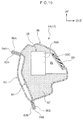
- a vicinity information detection sensor arrangement in accordance with a first exemplary embodiment of the present invention is employed is described with reference to Fig. 1 to Fig. 3 .
- the arrow FR that is shown as appropriate in the drawings indicates the vehicle forward side of the autonomous driving vehicle in which the vicinity information detection sensor is mounted, the arrow UP indicates the vehicle upper side, and the arrow OUT indicates a vehicle width direction outer side.
- the directions front, rear, up, down, left and right are used without being particularly specified, the same represent the front and rear in the vehicle front-and-rear direction, up and down in the vehicle up-and-down direction, and left and right if facing in the running direction.
- a roof panel 12 is disposed at a vehicle upper portion of an autonomous driving vehicle 10 (hereinafter referred to simply as "the vehicle 10").
- the vehicle 10 an autonomous driving vehicle 10
- a pair of left and right roof side rails 14 are disposed at the two vehicle width direction sides of the roof panel 12.
- Each roof side rail 14 extends in the vehicle front-and-rear direction.
- a front header and a rear header which are not shown in the drawings, span across in the vehicle width direction between the pair of roof side rails 14.
- the front header spans between front end portions of the roof side rails 14 and the rear header spans between rear end portions of the roof side rails 14.
- a front pillar 16 extends to the vehicle lower side from the front end portion of each roof side rail 14.
- the front pillar 16 serves as a vehicle framework member.
- a center pillar 18 extends to the vehicle lower side from the roof side rail 14 at the vehicle rear relative to the front pillar 16.
- a rear pillar 20 extends to the vehicle lower side from the roof side rail 14 at the vehicle rear relative to the center pillar 18.
- the front pillar 16, the center pillar 18 and the rear pillar 20 are each provided as pairs at left and right.
- a transmissive member 38 that serves as a cover is provided at an upper portion of each front pillar 16.
- a vicinity information detection sensor 34 is disposed at the vehicle inner side of the transmissive member 38 (see Fig. 2 ).
- a controller 22 that serves as a control unit is provided in the vehicle 10.
- the controller 22 controls running of the vehicle 10 in accordance with vicinity information detected by each vicinity information detection sensor 34 and the like.
- the vicinity information detection sensor 34 is electronically connected to the controller 22.
- the controller 22 is also electronically connected to electronic power steering (EPS), a brake electronic control unit (ECU) and so forth.
- EPS electronic power steering
- ECU brake electronic control unit
- the controller 22 is configured to be capable of controlling running of the vehicle 10 without a driver driving the vehicle 10.
- the controller 22 is configured to be switchable between an automatic driving mode, in which the controller 22 controls running of the vehicle 10 in accordance with vicinity information detected by the vicinity information detection sensor 34, and a manual driving mode, in which a driver personally operates a steering wheel, which is not shown in the drawings, and causes running of the vehicle 10.
- a location at which the controller 22 is installed is not limited by the present exemplary embodiment but may be suitably modified in accordance with positions of the vicinity information detection sensor 34.
- the above-mentioned driving modes are also not limiting. Other embodiments are possible where assisted driving can be done using vicinity information detected by the vicinity information detection sensor 34 (high-level driving support).
- the front pillar 16 is formed as a closed cross section structure that includes a front pillar inner panel 24 and a front pillar outer panel 26.
- the front pillar inner panel 24 is disposed at the vehicle inner side and extends in the vehicle up-and-down direction, and is formed of a member with electrical conductivity.
- a cross section of the front pillar inner panel 24 cut up-and-down along the vehicle width direction is formed substantially in a hat shape that is open to the vehicle upper side and the vehicle width direction outer side.
- An inner side inner flange 24A protrudes to the vehicle width direction inner side and the vehicle upper side from a vehicle width direction inner side end portion of the front pillar inner panel 24.
- An inner side outer flange 24B protrudes to the vehicle width direction outer side and the vehicle lower side from a vehicle width direction outer side end portion of the front pillar inner panel 24.
- the front pillar outer panel 26 is disposed at the vehicle outer side relative to the front pillar inner panel 24.
- the front pillar outer panel 26 extends in the vehicle up-and-down direction and is formed of a member that features electrical conductivity.
- a cross section of the front pillar outer panel 26 cut up-and-down along the vehicle width direction is formed substantially in a hat shape that is open to the vehicle lower side and the vehicle width direction inner side.
- An outer side inner flange 26A protrudes along the inner side inner flange 24A from a vehicle width direction inner side end portion of the front pillar outer panel 26.
- the outer side inner flange 26A and the inner side inner flange 24A are joined together by welding or the like.
- An outer side outer flange 26B protrudes along the inner side outer flange 24B from a vehicle width direction outer side end portion of the front pillar outer panel 26.
- the outer side outer flange 26B and the inner side outer flange 24B are joined together by welding or the like.
- An insertion hole 26C is formed in the front pillar outer panel 26.
- a mounting bracket 28 is joined to a hole edge of the insertion hole 26C.
- a portion of the insertion hole 26C is covered by the mounting bracket 28.
- the vicinity information detection sensor 34 is mounted to the front pillar outer panel 26 via the mounting bracket 28.
- the mounting bracket 28 is provided with a bracket main body portion 30 that is formed in a substantially rectangular shape.
- Bolt holes 30A are formed at each of the four comers of the bracket main body portion 30.
- the mounting bracket 28 is fastened (joined) to the hole edge of the insertion hole 26C of the front pillar outer panel 26 by fasteners such as bolts or the like, which are not shown in the drawings, being inserted into the bolt holes 30A.
- a substantially rectangular sensor mounting hole 30B is formed at a central region of the bracket main body portion 30.
- An upper support piece 32 is projected to the vehicle width direction outer side from an upper edge of the sensor mounting hole 30B, and a lower support piece 33 is projected to the vehicle width direction inner side from a lower edge of the sensor mounting hole 30B.
- the vicinity information detection sensor 34 is inserted into the sensor mounting hole 30B, and is fitted in between the upper support piece 32 and the lower support piece 33 and supported from above and below by the same.
- a portion of the vicinity information detection sensor 34 is inserted inside the front pillar 16 through the insertion hole 26C of the front pillar outer panel 26.
- the vicinity information detection sensor 34 is provided with a detection portion 34A.
- the detection portion 34A is oriented to the vehicle outer side of the vicinity information detection sensor 34 and is configured such that vicinity information of the vehicle 10 may be detected by the detection portion 34A.
- a millimeter wave radar is employed as the vicinity information detection sensor 34 and an electromagnetic wave transmission unit and reception unit constitute the detection portion 34A, but this is not limiting.
- a laser radar, an ultrasound sensor, an optical camera or the like may be employed, and alternative sensors may be employed.
- a laser radar is employed as the vicinity information detection sensor 34
- a laser light emission unit and laser light detection unit constitute the detection portion.
- an ultrasound sensor is employed as the vicinity information detection sensor 34
- an acoustic transmitter and an acoustic receiver constitute the detection portion.
- an optical camera is employed as the vicinity information detection sensor 34, a visible light detection unit constitutes the detection portion.
- the transmissive member 38 is disposed at the vehicle outer side relative to the vicinity information detection sensor 34.
- the transmissive member 38 is mounted at a side outer panel (a side member outer) 36. Accordingly, via the side outer panel 36, the transmissive member 38 is mounted on the front pillar 16 (the framework member 16).
- a cross section of the side outer panel 36 cut up-and-down along the vehicle width direction is formed substantially in a hat shape that is open to the vehicle lower side and the vehicle width direction inner side.
- An inner flange 36A protrudes along the outer side inner flange 26A from a vehicle width direction inner side end portion of the side outer panel 36.
- the inner flange 36A is joined to both the inner side inner flange 24A and the outer side inner flange 26A by welding or the like.
- An outer flange 36B protrudes along the outer side outer flange 26B from a vehicle width direction outer side end portion of the side outer panel 36.
- the outer flange 36B is joined to both the inner side outer flange 24B and the outer side outer flange 26B by welding or the like.
- a cover mounting hole 36C is formed at a location of the side outer panel 36 that opposes the detection portion 34A of the vicinity information detection sensor 34 in the vehicle width direction.
- the transmissive member 38 is mounted at the cover mounting hole 36C. Thus, the transmissive member 38 is disposed at a location opposing the detection portion 34A in the vehicle width direction.
- the transmissive member 38 is formed of a material that allows transmission of a detection carrier that the detection portion 34A of the vicinity information detection sensor 34 detects.
- the transmissive member 38 according to the present exemplary embodiment is formed of a non-transparent resin material that transmits electromagnetic waves.
- the transmissive member 38 is the same color as the side outer panel 36.
- the transmissive member 38 may be formed of a transparent resin material that transmits laser light, visible light or the like.
- an ultrasound sensor is employed as the vicinity information detection sensor 34
- the transmissive member 38 may be formed of a material that transmits ultrasound waves.
- cover 38 altogether with the inner panel 24 and the side outer panel 36, delimits a closed volume in which the vicinity information sensor 34 is located.
- the vehicle 10 is caused to run in accordance with vicinity information detected by the vicinity information detection sensor 34 mounted at the front pillar 16 and suchlike. More specifically, information on the vicinity of the vehicle 10 is detected by the detection portion 34A of the vicinity information detection sensor 34 and this vicinity information is sent to the controller 22 via a wire harness, which is not shown in the drawings. Hence, by signals being sent from the controller 22 to the EPS, the brake ECU and the like, running of the vehicle 10 is controlled in accordance with the vicinity information acquired from the vicinity information detection sensor 34 and suchlike.
- the vicinity information detection sensor 34 is mounted at the front pillar 16 with the closed cross section structure constituted by the front pillar inner panel 24 and the front pillar outer panel 26, and a portion of the vicinity information detection sensor 34 is disposed inside the front pillar 16.
- a protrusion amount of the vicinity information detection sensor 34 to the vehicle outer side may be decreased.
- air resistance acting on the vehicle 10 during running may be reduced compared to a structure in which the vicinity information detection sensor 34 is disposed on a roof panel, a structure in which the vicinity information detection sensor 34 is mounted at the vehicle outer side of a vehicle framework member, or the like.
- the transmissive member 38 is disposed at a location opposing the detection portion 34A of the vicinity information detection sensor 34, and the vicinity information detection sensor 34 is covered from the vehicle outer side thereof by the transmissive member 38. Therefore, there is no need to expose the vicinity information detection sensor 34 at the vehicle outer side and the appearance of the vehicle 10 may be improved compared to a structure in which the vicinity information detection sensor 34 is exposed.
- the transmissive member 38 transmits the detection carrier that the detection portion 34A uses for detection (i.e., electromagnetic waves in the present exemplary embodiment), vicinity information of the vehicle 10 may be detected, similarly to a structure in which the vicinity information detection sensor 34 is disposed at the outer side of a vehicle.
- the transmissive member 38 is formed of a non-transparent resin material and is made to be the same color as the side outer panel 36. Therefore, the transmissive member 38 is not obvious and the visual design of the vehicle 10 may be improved.
- the mounting bracket 28 is joined to the hole edge of the insertion hole 26C formed in the front pillar outer panel 26 and a portion of the insertion hole 26C is covered by the mounting bracket 28. Therefore, even though the insertion hole 26C for inserting the vicinity information detection sensor 34 is formed in the front pillar outer panel 26, a reduction in stiffness of the front pillar outer panel 26 (and the front pillar 16) may be suppressed. Moreover, a vicinity information detection sensor with a different shape may be mounted simply by altering the shape, size and the like of the mounting bracket 28.
- the front pillar 16 is constituted of a material with electrical conductivity, effects of electromagnetic noise generated inside a vehicle cabin on the vicinity information detection sensor 34 may be suppressed.
- the vicinity information detection sensor 34 might be affected by electromagnetic waves (electromagnetic noise) generated from audio equipment, switches and the like inside the vehicle cabin.
- electromagnetic waves generated from inside the vehicle cabin that are directed towards the vicinity information detection sensor 34 are blocked by the front pillar 16. Therefore, the effects of electromagnetic noise from inside the vehicle cabin on the vicinity information detection sensor 34 may be suppressed. That is, electromagnetic noise generated from inside the vehicle cabin is blocked by the front pillar 16 while the detection carrier that the vicinity information detection sensor 34 detects passes through the transmissive member 38. Thus, the detection accuracy of the vicinity information detection sensor 34 may be excellently maintained.
- a transmissive member 48 that serves as the cover is disposed at an upper portion of the rear pillar 20, which serves as a vehicle framework member structuring an autonomous driving vehicle 40 (hereinafter referred to simply as "the vehicle 40").
- the vicinity information detection sensor 34 is disposed at the vehicle inner side of the transmissive member 48.
- the rear pillar 20 is formed as a closed cross section structure that includes a rear pillar inner panel 42 and a rear pillar outer panel 44.
- the rear pillar inner panel 42 is disposed at the vehicle inner side and is formed of a member that features electrical conductivity.
- An inner side inner flange 42A protrudes to the vehicle width direction inner side and the vehicle upper side from a vehicle width direction inner side end portion of the rear pillar inner panel 42.
- An inner side outer flange 42B protrudes to the vehicle width direction outer side and the vehicle lower side from a vehicle width direction outer side end portion of the rear pillar inner panel 42.
- the rear pillar outer panel 44 is disposed at the vehicle outer side relative to the rear pillar inner panel 42 and is formed of a member that features electrical conductivity.
- An outer side inner flange 44A protrudes along the inner side inner flange 42A from a vehicle width direction inner side end portion of the rear pillar outer panel 44.
- the outer side inner flange 44A and the inner side inner flange 42A are joined together by welding or the like.
- An outer side outer flange 44B protrudes along the inner side outer flange 42B from a vehicle width direction outer side end portion of the rear pillar outer panel 44.
- the outer side outer flange 44B and the inner side outer flange 42B are joined together by welding or the like.
- An insertion hole 44C is formed in the rear pillar outer panel 44.
- the mounting bracket 28 is joined to a hole edge of the insertion hole 44C.
- the vicinity information detection sensor 34 is mounted to the rear pillar outer panel 44 via the mounting bracket 28. Specifically, the vicinity information detection sensor 34 is inserted into the sensor mounting hole 30B of the bracket main body portion 30, and is fitted in between the upper support piece 32 and the lower support piece 33 and supported by the same.
- the transmissive member 48 is disposed at the vehicle outer side relative to the vicinity information detection sensor 34.
- the transmissive member 48 is mounted at a side outer panel (a side member outer) 46.
- a cross section of the side outer panel 46 cut up-and-down along the vehicle width direction is formed substantially in a hat shape that is open to the vehicle lower side and the vehicle width direction inner side.
- An inner flange 46A protrudes along the outer side inner flange 44A from a vehicle width direction inner side end portion of the side outer panel 46.
- the inner flange 46A is joined to both the inner side inner flange 42A and the outer side inner flange 44A by welding or the like.
- An outer flange 46B protrudes along the outer side outer flange 44B from a vehicle width direction outer side end portion of the side outer panel 46.
- the outer flange 46B is joined to both the inner side outer flange 42B and the outer side outer flange 44B by welding or the like.
- a cover mounting hole 46C is formed at a location of the side outer panel 46 that opposes the detection portion 34A of the vicinity information detection sensor 34 in the vehicle width direction.
- the transmissive member 48 is mounted at the cover mounting hole 46C. Thus, the transmissive member 48 is disposed at a location opposing the detection portion 34A in the vehicle width direction.
- a portion of the vicinity information detection sensor 34 is disposed inside the rear pillar 20.
- a protrusion amount of the vicinity information detection sensor 34 to the vehicle outer side may be decreased.
- vicinity information detection sensor 34 is disposed at the rear pillar 20, vicinity information to the vehicle rear side in particular may be effectively detected.
- Other operations are the same as in the first exemplary embodiment.
- a roof reinforcement 51 that serves as a vehicle framework member is arranged in the vehicle width direction along the roof panel 12, which structures an autonomous driving vehicle 50 (hereinafter referred to simply as "the vehicle 50").
- a vicinity information detection sensor 58 is mounted at this roof reinforcement 51.
- the roof reinforcement 51 includes a roof lower panel 52 and a roof upper panel 54 and is formed with a closed cross section structure.
- the roof reinforcement 51 is formed of members that feature electrical conductivity.
- the roof lower panel 52 is disposed at the vehicle inner side and a cross section thereof cut up-and-down along the vehicle front-and-rear direction is formed substantially in a hat shape that is open to the vehicle upper side.
- a lower side front flange 52A protrudes to the vehicle forward side from a front end portion of the roof lower panel 52.
- a lower side rear flange 52B protrudes to the vehicle rearward side from a rear end portion of the roof lower panel 52.
- the roof upper panel 54 is disposed at the vehicle outer side relative to the roof lower panel 52.
- a cross section of the roof upper panel 54 cut up-and-down along the vehicle front-and-rear direction is formed substantially in a flat hat shape that is open to the vehicle upper side.
- An upper side front flange 54A protrudes along the lower side front flange 52A from a front end portion of the roof upper panel 54.
- the upper side front flange 54A and the lower side front flange 52A are joined together by welding or the like, and the upper side front flange 54A is joined to a lower face of the roof panel 12.
- An upper side rear flange 54B protrudes along the lower side rear flange 52B from a rear end portion of the roof upper panel 54.
- the upper side rear flange 54B and the lower side rear flange 52B are joined together by welding or the like, and the upper side rear flange 54B is joined to the lower face of the roof panel 12.
- An insertion hole 54C is formed, in a substantially circular shape in plan view, in a central region of the roof upper panel 54.
- the vicinity information detection sensor 58 is mounted at the insertion hole 54C via a bracket 56.
- the bracket 56 is formed in the shape of a circular tube with a bottom that is open to the vehicle upper direction.
- the bracket 56 is inserted inside the roof reinforcement 51.
- An upper flange 56A protrudes to the outer periphery side from an upper end portion of the bracket 56.
- the upper flange 56A is joined to a hole edge of the insertion hole 54C.
- the vicinity information detection sensor 58 is disposed at the inner periphery side of the bracket 56.
- the vicinity information detection sensor 58 according to the present exemplary embodiment is formed substantially in a circular rod shape. A lower portion of the vicinity information detection sensor 58 is tightly fitted into the bracket 56.
- Plural detection portions 58A are provided at an upper portion of the vicinity information detection sensor 58, spaced apart at an outer periphery face thereof. (Only two of the detection portions 58A are shown in Fig. 6 .) Each detection portion 58A is oriented to the vehicle outer side and is configured such that vicinity information of the vehicle 50 may be detected by the detection portion 58A.
- a millimeter wave radar is employed as the vicinity information detection sensor 58, but this is not limiting and alternative sensors may be employed.
- An opening 12A is formed in a region of the roof panel 12 in which the vicinity information detection sensor 58 is disposed.
- the opening 12A is closed off by a transmissive member 59 that serves as a cover.
- the transmissive member 59 is disposed at the vehicle upper side of the vicinity information detection sensor 58 and is formed in a substantially circular shape in plan view.
- a bulge portion 59A which bulges to the vehicle upper direction, is formed at a central portion of the transmissive member 59.
- the vicinity information detection sensor 58 that protrudes to the vehicle upper side relative to the roof panel 12 is covered from the vehicle upper side thereof by this bulge portion 59A.
- the transmissive member 59 is formed of a material that allows transmission of a detection carrier that the detection portions 58A use for detection.
- the transmissive member 59 according to the present exemplary embodiment is formed of a non-transparent resin material.
- the transmissive member 59 is the same color as the roof panel 12.
- the bulge portion 59A of the transmissive member 59 is formed so as to oppose the detection portions 58A in the vehicle front-and-rear direction and the vehicle width direction.
- a portion of the vicinity information detection sensor 58 is disposed inside the roof reinforcement 51.
- a protrusion amount of the vicinity information detection sensor 58 to the vehicle outer side may be reduced.
- the protrusion amount of the vicinity information detection sensor 58 is made small, a protrusion amount of the bulge portion 59A of the transmissive member 59 that covers the vicinity information detection sensor 58 may be made small. Thus, air resistance during running may be reduced. Hence, aerodynamic characteristics may be improved compared to a structure in which the vicinity information detection sensor 58 is disposed on a roof panel, a structure in which the vicinity information detection sensor 58 is mounted at the vehicle outer side of a vehicle framework member, or the like. Further, because the protrusion amount of the bulge portion 59A is made small, the appearance of the vehicle 50 may be improved compared to a vehicle in which the vicinity information detection sensor 58 protrudes greatly from the roof panel 12.
- an autonomous driving vehicle 60 (hereinafter referred to simply as “the vehicle 60") according to the present exemplary embodiment is provided, at a vehicle side portion, with a front side door 62 and a rear side door 64.
- a vicinity information detection sensor 70 according to the present exemplary embodiment is disposed at an upper portion of the center pillar 18 (a joining portion of the center pillar 18 to the roof side rail 14).
- the center pillar 18 serves as a vehicle framework member that is disposed between the front side door 62 and the rear side door 64.
- a front door frame 66 that supports an outer periphery portion of a front side glass 63 is provided at an upper portion of the front side door 62
- a rear door frame 68 that supports an outer periphery portion of a rear side glass 65 is provided at an upper portion of the rear side door 64.
- a transmissive member 72 that serves as a cover is provided between the front door frame 66 and the rear door frame 68.
- the vicinity information detection sensor 70 is disposed at the vehicle inner side of the transmissive member 72.
- the center pillar 18 is formed as a closed cross section structure that includes a center pillar inner panel 74 and a center pillar outer panel 76.
- the center pillar 18 is formed of members which are electrically conductive.
- the center pillar inner panel 74 is disposed at the vehicle inner side.
- a cross section of the center pillar inner panel 74 cut front-and-rear along the vehicle width direction is formed substantially in a hat shape that is open to the vehicle width direction outer side.
- An inner side front flange 74A protrudes to the vehicle forward side from a front end portion of the center pillar inner panel 74.
- An inner side rear flange 74B protrudes to the vehicle real-ward side from a rear end portion of the center pillar inner panel 74.
- the center pillar outer panel 76 is disposed at the vehicle width direction outer side relative to the center pillar inner panel 74.
- a cross section of the center pillar outer panel 76 cut front-and-rear along the vehicle width direction is formed substantially in a hat shape that is open to the vehicle width direction inner side.
- An outer side front flange 76A protrudes along the inner side front flange 74A from a front end portion of the center pillar outer panel 76.
- the outer side front flange 76A and the inner side front flange 74A are joined together by welding or the like.
- An outer side rear flange 76B protrudes along the inner side rear flange 74B from a rear end portion of the center pillar outer panel 76.
- the outer side rear flange 76B and the inner side rear flange 74B are joined together by welding or the like.
- An insertion hole 76C is formed in the center pillar outer panel 76.
- a bracket 78 is joined to a hole edge of the insertion hole 76C.
- the vicinity information detection sensor 70 is mounted to the center pillar outer panel 76 via the bracket 78.
- the bracket 78 is formed in a substantial hat shape in cross section that is open to the vehicle width direction outer side.
- the bracket 78 is inserted inside the center pillar 18.
- a flange protrudes to the outer periphery side from an opening of the bracket 78. This flange is joined to a hole edge of the insertion hole 76C.
- the vicinity information detection sensor 70 is disposed at the bracket 78 that is structured as described above. A portion of the vicinity information detection sensor 70 is tightly fitted into the bracket 78.
- a detection portion 70A is provided at the vehicle width direction outer side of the vicinity information detection sensor 70.
- the detection portion 70A is oriented to the vehicle outer side and is configured such that vicinity information of the vehicle 60 may be detected by the detection portion 70A.
- a millimeter wave radar is employed as the vicinity information detection sensor 70, but this is not limiting and alternative sensors may be employed.
- the transmissive member 72 is disposed at the vehicle width direction outer side relative to the vicinity information detection sensor 70.
- a cross section of the transmissive member 72 cut front-and-rear along the vehicle width direction is formed substantially in a "U" shape that is open to the vehicle width direction inner side.
- the transmissive member 72 is mounted to the bracket 78 or the center pillar outer panel 76 so as to cover the vicinity information detection sensor 70.
- the transmissive member 72 is formed of a material that allows transmission of a detection carrier that the detection portion 70A uses for detection.
- the transmissive member 72 according to the present exemplary embodiment is formed of a non-transparent resin material.
- the transmissive member 72 is the same color as the center pillar 18.
- the transmissive member 72 is disposed so as to overlap with the front door frame 66 and the rear door frame 68 when viewed in the vehicle width direction.
- a portion of the vicinity information detection sensor 70 is disposed inside the center pillar 18.
- a protrusion amount of the vicinity information detection sensor 70 to the vehicle outer side may be made small, and aerodynamic characteristics of the vehicle 60 may be improved compared to a structure in which the vicinity information detection sensor 70 is disposed on a roof panel, a structure in which the vicinity information detection sensor 70 is mounted at the vehicle outer side of a vehicle framework member, or the like.
- the vicinity information detection sensor 70 may be disposed at the center pillar 18 and information on the vicinity of the vehicle side portion may be effectively detected. Other operations are the same as in the first exemplary embodiment.
- a transmissive member 89 that serves as a cover is disposed at the roof side rail 14 that serves as a vehicle framework member disposed at the vehicle upper portion.
- a vicinity information detection sensor 88 is disposed at the vehicle inner side of the transmissive member 89.
- the roof side rail 14 is formed as a closed cross section structure that includes a roof side rail inner panel 82, a roof side rail outer panel 86 and an outer reinforcement 84.
- the roof side rail inner panel 82 is disposed at the vehicle inner side and extends in the vehicle up-and-down direction.
- An inner side upper flange 82A protrudes to the vehicle width direction inner side from an upper end portion of the roof side rail inner panel 82.
- An inner side lower flange 82B protrudes to the vehicle lower side from a lower end portion of the roof side rail inner panel 82.
- the roof side rail outer panel 86 is disposed at the vehicle width direction outer side relative to the roof side rail inner panel 82.
- a cross section of the roof side rail outer panel 86 cut up-and-down along the vehicle width direction is formed substantially in a hat shape that is open to the vehicle width direction inner side.
- An outer side upper flange 86A protrudes along the inner side upper flange 82A from an upper end portion of the roof side rail outer panel 86.
- An outer side lower flange 86B protrudes along the inner side lower flange 82B from a lower end portion of the roof side rail outer panel 86.
- the outer reinforcement 84 is disposed between the roof side rail inner panel 82 and the roof side rail outer panel 86.
- the outer reinforcement 84 extends along the roof side rail inner panel 82 in the vehicle up-and-down direction.
- An upper flange 84A protrudes to the vehicle width direction inner side from an upper end portion of the outer reinforcement 84.
- the upper flange 84A is joined to both the inner side upper flange 82A and the outer side upper flange 86A by welding or the like.
- a lower flange 84B protrudes to the vehicle width direction inner side from a lower end portion of the outer reinforcement 84.
- the lower flange 84B is joined to both the inner side lower flange 82B and the outer side lower flange 86B by welding or the like.
- the roof side rail 14 is structured with a closed cross section between the roof side rail inner panel 82 and the outer reinforcement 84 and is structured with a closed cross section between the outer reinforcement 84 and the roof side rail outer panel 86.
- the vicinity information detection sensor 88 is disposed between the outer reinforcement 84 and the roof side rail outer panel 86. In the present exemplary embodiment, the whole of the vicinity information detection sensor 88 is disposed inside the roof side rail 14. A foam material 87 that serves as a shock-absorbing member is provided between the vicinity information detection sensor 88 and the outer reinforcement 84 and roof side rail outer panel 86. Hence, the vicinity information detection sensor 88 is supported by the foam material 87.
- a detection portion 88A is provided at the vehicle width direction outer side of the vicinity information detection sensor 88.
- the detection portion 88A is oriented to the vehicle outer side and is configured such that vicinity information of the vehicle 80 may be detected by the detection portion 88A.
- a millimeter wave radar is employed as the vicinity information detection sensor 88, but this is not limiting and alternative sensors may be employed.
- An opening 86C is formed in the roof side rail outer panel 86.
- the transmissive member 89 is mounted at the opening 86C and the opening 86C is closed off by the transmissive member 89.
- the transmissive member 89 is disposed to oppose the detection portion 88A and is formed of a material that allows transmission of a detection carrier that the detection portion 88A uses for detection.
- the transmissive member 89 according to the present exemplary embodiment is formed of a non-transparent resin material.
- a region between the detection portion 88A and the transmissive member 89 is a cavity portion 85 that is not filled with the foam material 87.
- the vehicle 80 in which the vicinity information detection sensor arrangement for the vicinity information detection sensor 88 according to the present exemplary embodiment is employed are described.
- the whole of the vicinity information detection sensor 88 is disposed inside the roof side rail 14. Therefore, the vehicle 80 may be formed with the same external shape as a vehicle that is not equipped with the vicinity information detection sensor 88. That is, there is no bulging of the roof side rail 14 to the vehicle outer side due to the vicinity information detection sensor 88. Thus, aerodynamic characteristics the same as for a vehicle that is not equipped with the vicinity information detection sensor 88 may be obtained.
- the opening 86C of the roof side rail outer panel 86 is closed off by the transmissive member 89, ingressions of rainwater or foreign matter into the cross section or suchlike and a consequent degradation of the detection accuracy of the vicinity information detection sensor 88 may be avoided.
- the foam material 87 is provided around the vicinity information detection sensor 88, when a load acts on the roof side rail 14 from the exterior, a portion of this load is absorbed by the foam material 87 and the vicinity information detection sensor 88 may be protected. That is, shock resistance performance of the vicinity information detection sensor 88 may be improved.
- vicinity information detection sensor 88 is disposed at the roof side rail 14, vicinity information may be detected over a wide range from the vehicle upper portion. Other operations are the same as in the first exemplary embodiment.
- the vicinity information detection sensor 88 is disposed at the roof side rail 14 located between the front pillar 16 and the center pillar 18, but the present invention is not limited to this embodiment.
- the vicinity information detection sensor 88 may be disposed at a joining portion 94 of the center pillar 18 and the roof side rail 14. Because the joining portion 94 between the roof side rail 14 and the center pillar 18 has a higher stiffness than general portions of the roof side rail 14, mounting stiffness of the vicinity information detection sensor 88 may be assured by the vicinity information detection sensor 88 being disposed at the joining portion 94. As a result, vibrations acting on the vicinity information detection sensor 88 during running may be reduced, and detection accuracy may be improved.
- the foam material 87 is employed as the shock-absorbing member but the present invention is not limited thus.
- a resilient body of rubber or the like, or a gel or the like may be employed.
- the foam material 87 is provided between the vicinity information detection sensor 88 and the outer reinforcement 84 and roof side rail outer panel 86, but the present invention is not limited thus.
- the vicinity information detection sensor 88 may be mounted using an installation bracket 92.
- the vicinity information detection sensor 88 is disposed between the outer reinforcement 84 and the roof side rail outer panel 86.
- the installation bracket 92 spans across the interior of the roof side rail 14 (between the outer reinforcement 84 and the roof side rail outer panel 86).
- the vicinity information detection sensor 88 is mounted to the roof side rail 14 via the installation bracket 92.
- the installation bracket 92 extends in the vehicle width direction.
- An inner flange 92A protrudes along the outer reinforcement 84 from a vehicle width direction inner side end portion of the installation bracket 92.
- the inner flange 92A is joined to the outer reinforcement 84.
- An outer flange 92B protrudes along the roof side rail outer panel 86 from a vehicle width direction outer side end portion of the installation bracket 92.
- the outer flange 92B is joined to the roof side rail outer panel 86.
- a mounting hole 92C is formed in a vehicle width direction central region of the installation bracket 92.
- a lower end portion of the vicinity information detection sensor 88 is inserted into the mounting hole 92C and mounted.
- a hole edge of the mounting hole 92C is inflected to the vehicle upper side along the vicinity information detection sensor 88 and supports an outer periphery face of the vicinity information detection sensor 88.
- the installation bracket 92 is installed in the roof side rail 14, the efficiency of transmission of loads that act on the roof side rail 14 may be improved. As a result, stiffness of the roof side rail 14 may be raised.
- the shape of the roof side rail outer panel 86 is altered and the opening face of the opening 86C is formed to face diagonally downward. Because the transmissive member 89 is mounted at this opening 86C, the transmissive member 89 is disposed so as to be inclined toward the vehicle width direction inner side in the direction from the vehicle upper side to the vehicle lower side.
- the outer face of the transmissive member 89 faces diagonally downward in the present variant example, dirt is less likely to adhere to the transmissive member 89 even when there is rain. Thus, the detection accuracy of the vicinity information detection sensor 88 may be excellently maintained.
- the first to fifth exemplary embodiments of the present invention have been described hereabove but the present invention is not limited by the above-described structures and it will be clear that the present invention may be embodied in numerous modes beside the above structures within a scope that does not depart from the spirit of the present invention.
- structures are described in which a vicinity information detection sensor is disposed at the vehicle left side, but the present invention is not limited thus.
- a vicinity information detection sensor may be disposed at the vehicle right side, and a pair of vicinity information detection sensors may be disposed at the vehicle right side and the vehicle left side.
- the structures of the above exemplary embodiments may be combined.
- a structure may be formed in which respective vicinity information detection sensors are disposed at a front pillar, a rear pillar and a roof side rail.
- each transmissive member is formed of a non-transparent resin material but the present invention is not limited thus.
- a transmissive member may be formed of an alternative material provided the member allows transmission of the detection carrier that is detected by the detection portion of the vicinity information detection sensor.
- the transmissive member may be formed of a transparent resin material that transmits laser light, visible light or the like
- the transmissive member may be formed of a material that transmits ultrasound waves.
- a vicinity information detection sensor is disposed inside a closed cross section structure of a vehicle framework member, the location at which the vicinity information detection sensor is disposed may be, apart from the locations described in the above exemplary embodiments, a rocker, a belt line reinforcement or the like.
- a shock-absorbing member such as a foam material or the like is not provided inside the vehicle framework member, but this is not limiting and structures are possible in which a shock-absorbing member is provided.
- a shock-absorbing member that is a foam material or the like may be provided inside the front pillar 16 of Fig. 2 (i.e., between the front pillar inner panel 24 and the front pillar outer panel 26).
- the stiffness of the front pillar 16 may be raised and the vicinity information detection sensor 34 may be protected by the foam material.
- the shapes and sizes of the vicinity information detection sensors and the positions and shapes of the detection portions according to the above exemplary embodiments are not particularly limiting but may be suitably modified in accordance with types, positions of arrangement and the like of vicinity information detection sensors.
Landscapes
- Engineering & Computer Science (AREA)
- Physics & Mathematics (AREA)
- Remote Sensing (AREA)
- Radar, Positioning & Navigation (AREA)
- Mechanical Engineering (AREA)
- Computer Networks & Wireless Communication (AREA)
- General Physics & Mathematics (AREA)
- Transportation (AREA)
- Electromagnetism (AREA)
- Combustion & Propulsion (AREA)
- Chemical & Material Sciences (AREA)
- Automation & Control Theory (AREA)
- Mathematical Physics (AREA)
- Body Structure For Vehicles (AREA)
Abstract
Description
- The present invention relates to a vicinity information detection sensor arrangement.
- Japanese Patent Application Laid-Open (
JP-A) No. 2005-291808 - In a case of autonomous driving using a vicinity information detection sensor, the situation in all directions must be ascertained. Accordingly, a structure is known, as in the technology recited in the above-mentioned
JP-A No. 2005-291808 - In consideration of the circumstances described above, an object of the present invention is to provide avicinity information detection sensor arrangement that improves aerodynamic characteristics and appearance.
- A vicinity information detection sensor arrangement according to a first aspect of the present invention includes: a vehicle framework member having a closed cross section structure; and a vicinity information detection sensor, provided at the vehicle framework member; at least a portion of the vicinity information detection sensor being disposed inside the vehicle framework member; a detection portion of the vicinity information detection sensor that detects vicinity information of the vehicle being oriented to a vehicle outer side; and a cover, mounted on the vehicle framework member, and that faces the detection portion and allows transmission of a detection carrier that the detection portion uses for detection.
- In the vicinity information detection sensor arrangement according to the first aspect of the present invention, the vicinity information detection sensor is provided at the vehicle framework member that is structured with a closed cross section, and at least a portion of the vehicle information detection sensor is disposed inside the vehicle framework member. Consequently, a protrusion amount of the vehicle information detection sensor to the vehicle outer side may be made smaller than in a structure in which the vicinity information detection sensor is disposed on a roof panel, a structure in which the vicinity information detection sensor is mounted at the vehicle outer side of a vehicle framework member, or the like. As a result, air resistance acting on the vehicle during running may be reduced.
- The cover may be mounted directly or indirectly (i.e., using a bracket or the like) on the vehicle framework member.
- A framework member having a closed cross section structure is a framework member which generally has a closed cross-section, but may have openings where the cross-section is not closed.
- The vicinity information detection sensor according to the first aspect is provided with the detection portion that is oriented to the vehicle outer side and detects vicinity information. The cover is disposed at a location opposing this detection portion. Consequently, there is no need to expose the vicinity information detection sensor at the vehicle outer side and the appearance of the vehicle may be improved. Further, because the cover transmits the detection carrier that the detection portion uses for detection, information on the vicinity of the vehicle may be detected, similarly to a structure in which a vicinity information detection sensor is disposed at the outer side of a vehicle. The term "detection carrier" as used herein refers to the general concept of various detection carriers and the like that can be detected by sensors, including electromagnetic waves, light and ultrasound.
- In a vicinity information detection sensor arrangement according to a second aspect of the present invention, in the first aspect, an insertion hole for insertion of the vicinity information detection sensor is formed in the vehicle framework member, and the vicinity information detection sensor is mounted on a mounting bracket that is joined to a hole edge of the insertion hole and that covers a portion of the insertion hole.
- In the vicinity information detection sensor arrangement according to the second aspect of the present invention, the vicinity information detection sensor is mounted on the mounting bracket that is joined to the hole edge of the insertion hole, and a portion of the insertion hole is covered by the mounting bracket. Therefore, even though the insertion hole is formed in the vehicle framework member, a reduction in stiffness of the vehicle framework member may be suppressed.
- In a vicinity information detection sensor arrangement according to a third aspect of the present invention, in the first aspect, the vicinity information detection sensor is disposed entirely inside the vehicle framework member, an opening is provided in the vehicle framework member at a location facing the detection portion, and the opening is closed off by the cover. The opening may comprise several apertures grouped together.
- In the vicinity information detection sensor arrangement according to the third aspect of the present invention, because the whole vicinity information detection sensor is disposed inside the vehicle framework member, aerodynamic characteristics equivalent to that of a vehicle that is not equipped with the vicinity information detection sensor may be obtained. Moreover, because the opening formed in the vehicle framework member is closed off by the cover, ingressions of foreign matter into the vehicle framework member and the like, and a consequent degradation of detection accuracy of the vicinity information detection sensor, may be avoided.
- In a vicinity information detection sensor arrangement according to a fourth aspect of the present invention, in the third aspect, the vicinity information detection sensor is mounted on an installation bracket that spans across an interior of the vehicle framework member.
- In the vicinity information detection sensor arrangement according to the fourth aspect of the present invention, because the installation bracket spans across the interior of the vehicle framework member, the efficiency of transmission of loads that act on the vehicle framework member may be improved.
- In a vicinity information detection sensor arrangement according to a fifth aspect of the present invention, in any one of the first to fourth aspects, a shock-absorbing member is provided between the vicinity information detection sensor and the vehicle framework member.
- In the vicinity information detection sensor arrangement according to the fifth aspect of the present invention, when a load acts on the vehicle framework member from the exterior, a portion of this load is absorbed by the shock-absorbing member. Thus, the vicinity information detection sensor may be protected.
- In a vicinity information detection sensor arrangement according to a sixth aspect of the present invention, in any one of the first to fifth aspects, the vehicle framework member is formed of an electrically conductive material.
- In the vicinity information detection sensor arrangement according to the sixth aspect of the present invention, because the vehicle framework member features electrical conductivity, electromagnetic waves generated inside the vehicle cabin that are directed towards the vicinity information detection sensor may be blocked by the vehicle framework member. Therefore, effects of electromagnetic noise on the vicinity information detection sensor may be suppressed.
- In a housing structure for a vicinity information detection sensor according to a seventh aspect of the present invention, in any one of the first to sixth aspects, the cover delimits a closed volume in which the vicinity information sensor is located.
- In the housing structure for a vicinity information detection sensor according to the sixth aspect of the present invention, because the cover delimits a closed volume in which the vicinity information sensor is located, the vicinity sensor can be protected.
- An eighth aspect of the present invention concerns a vehicle, comprising a housing structure according to any one of the first to seventh aspects of the invention, wherein the vicinity information detection sensor is disposed at a joining portion between a roof side rail and a center pillar.
- In the vehicle according to the eighth aspect of the present invention, because the vicinity information detection sensor is disposed at the joining portion of the roof side rail and the center pillar, which is disposed at a vehicle upper portion, vicinity information may be detected over a wide range from the vehicle upper portion. Further, because the joining portion of the roof side rail and pillar has a higher stiffness than general portions of the roof side rail, mounting stiffness of the vicinity information detection sensor may be assured by the vicinity information detection sensor being disposed at this joining portion. Therefore, vibrations acting on the vicinity information detection sensor during running may be reduced.
- As described hereabove, according to the vicinity information detection sensor arrangement according to the first aspect of the present invention, excellent effects are provided in that aerodynamic characteristics and appearance may be improved.
- According to the vicinity information detection sensor arrangement according to the second aspect of the present invention, an excellent effect is provided in that a reduction in stiffness of the vehicle framework member may be suppressed.
- According to the vicinity information detection sensor arrangement according to the third aspect of the present invention, an excellent effect is provided in that aerodynamic characteristics may be further improved.
- According to the vicinity information detection sensor arrangement according to the fourth aspect of the present invention, an excellent effect is provided in that stiffness of the vehicle framework member may be raised.
- According to the vicinity information detection sensor arrangement according to the fifth aspect of the present invention, an excellent effect is provided in that shock resistance performance of the vicinity information detection sensor may be improved.
- According to the vicinity information detection sensor arrangement according to the sixth aspect of the present invention, an excellent effect is provided in that a reduction in detection accuracy of the vicinity information detection sensor due to electromagnetic noise may be suppressed. According to the vicinity information detection sensor arrangement according to the seventh aspect of the present invention, an improved protection of the sensor can be ensured.
- According to the vehicle according to the eighth aspect of the present invention, excellent effects are provided in that information on the vicinity of the vehicle may be detected over a wide range while detection accuracy may be improved.
- Embodiments of the present invention will be described in detail based on the following figures, wherein:
-
Fig. 1 is a perspective view showing a vehicle in which a vicinity information detection sensor arrangement in accordance with a first exemplary embodiment is employed; -
Fig. 2 is a sectional diagram showing a section cut along line 2-2 ofFig. 1 in a magnified state; -
Fig. 3 is a perspective diagram showing a bracket for mounting the vicinity information detection sensor in accordance with the first exemplary embodiment; -
Fig. 4 is a perspective view showing a vehicle in which a vicinity information detection sensor arrangement in accordance with a second exemplary embodiment is employed; -
Fig. 5 is a sectional diagram showing a section cut along line 5-5 ofFig. 4 in a magnified state; -
Fig. 6 is a sectional diagram of a vehicle upper portion of a vehicle in which a vicinity information detection sensor arrangement in accordance with a third exemplary embodiment is employed; -
Fig. 7 is a perspective view showing a vehicle upper portion of a vehicle in which a vicinity information detection sensor arrangement in accordance with a fourth exemplary embodiment is employed; -
Fig. 8 is a sectional diagram showing a section cut along line 8-8 ofFig. 7 in a magnified state; -
Fig. 9 is a perspective view showing a vehicle in which a vicinity information detection sensor arrangement in accordance with a fifth exemplary embodiment is employed; -
Fig. 10 is a sectional diagram showing a section cut along line 10-10 ofFig. 9 in a magnified state; and -
Fig. 11 is a sectional diagram, corresponding toFig. 10 , showing a variant example of the vehicle in which the vicinity information detection sensor arrangement in accordance with the fifth exemplary embodiment is employed. - Herebelow, an autonomous driving vehicle in which a vicinity information detection sensor arrangement in accordance with a first exemplary embodiment of the present invention is employed is described with reference to
Fig. 1 to Fig. 3 . The arrow FR that is shown as appropriate in the drawings indicates the vehicle forward side of the autonomous driving vehicle in which the vicinity information detection sensor is mounted, the arrow UP indicates the vehicle upper side, and the arrow OUT indicates a vehicle width direction outer side. In the following descriptions, where the directions front, rear, up, down, left and right are used without being particularly specified, the same represent the front and rear in the vehicle front-and-rear direction, up and down in the vehicle up-and-down direction, and left and right if facing in the running direction. - As shown in
Fig. 1 , aroof panel 12 is disposed at a vehicle upper portion of an autonomous driving vehicle 10 (hereinafter referred to simply as "thevehicle 10"). A pair of left and right roof side rails 14 are disposed at the two vehicle width direction sides of theroof panel 12. - Each
roof side rail 14 extends in the vehicle front-and-rear direction. A front header and a rear header, which are not shown in the drawings, span across in the vehicle width direction between the pair of roof side rails 14. The front header spans between front end portions of the roof side rails 14 and the rear header spans between rear end portions of the roof side rails 14. - A
front pillar 16 extends to the vehicle lower side from the front end portion of eachroof side rail 14. Thefront pillar 16 serves as a vehicle framework member. Acenter pillar 18 extends to the vehicle lower side from theroof side rail 14 at the vehicle rear relative to thefront pillar 16. Arear pillar 20 extends to the vehicle lower side from theroof side rail 14 at the vehicle rear relative to thecenter pillar 18. Thefront pillar 16, thecenter pillar 18 and therear pillar 20 are each provided as pairs at left and right. In the present exemplary embodiment, atransmissive member 38 that serves as a cover is provided at an upper portion of eachfront pillar 16. A vicinityinformation detection sensor 34 is disposed at the vehicle inner side of the transmissive member 38 (seeFig. 2 ). - A
controller 22 that serves as a control unit is provided in thevehicle 10. Thecontroller 22 controls running of thevehicle 10 in accordance with vicinity information detected by each vicinityinformation detection sensor 34 and the like. The vicinityinformation detection sensor 34 is electronically connected to thecontroller 22. Thecontroller 22 is also electronically connected to electronic power steering (EPS), a brake electronic control unit (ECU) and so forth. Thecontroller 22 is configured to be capable of controlling running of thevehicle 10 without a driver driving thevehicle 10. In the present exemplary embodiment, thecontroller 22 is configured to be switchable between an automatic driving mode, in which thecontroller 22 controls running of thevehicle 10 in accordance with vicinity information detected by the vicinityinformation detection sensor 34, and a manual driving mode, in which a driver personally operates a steering wheel, which is not shown in the drawings, and causes running of thevehicle 10. A location at which thecontroller 22 is installed is not limited by the present exemplary embodiment but may be suitably modified in accordance with positions of the vicinityinformation detection sensor 34. The above-mentioned driving modes are also not limiting. Other embodiments are possible where assisted driving can be done using vicinity information detected by the vicinity information detection sensor 34 (high-level driving support). - As illustrated in
Fig. 2 , thefront pillar 16 is formed as a closed cross section structure that includes a front pillarinner panel 24 and a front pillarouter panel 26. - The front pillar
inner panel 24 is disposed at the vehicle inner side and extends in the vehicle up-and-down direction, and is formed of a member with electrical conductivity. A cross section of the front pillarinner panel 24 cut up-and-down along the vehicle width direction is formed substantially in a hat shape that is open to the vehicle upper side and the vehicle width direction outer side. An inner sideinner flange 24A protrudes to the vehicle width direction inner side and the vehicle upper side from a vehicle width direction inner side end portion of the front pillarinner panel 24. An inner sideouter flange 24B protrudes to the vehicle width direction outer side and the vehicle lower side from a vehicle width direction outer side end portion of the front pillarinner panel 24. - The front pillar
outer panel 26 is disposed at the vehicle outer side relative to the front pillarinner panel 24. The front pillarouter panel 26 extends in the vehicle up-and-down direction and is formed of a member that features electrical conductivity. A cross section of the front pillarouter panel 26 cut up-and-down along the vehicle width direction is formed substantially in a hat shape that is open to the vehicle lower side and the vehicle width direction inner side. An outer sideinner flange 26A protrudes along the inner sideinner flange 24A from a vehicle width direction inner side end portion of the front pillarouter panel 26. The outer sideinner flange 26A and the inner sideinner flange 24A are joined together by welding or the like. - An outer side
outer flange 26B protrudes along the inner sideouter flange 24B from a vehicle width direction outer side end portion of the front pillarouter panel 26. The outer sideouter flange 26B and the inner sideouter flange 24B are joined together by welding or the like. - An
insertion hole 26C is formed in the front pillarouter panel 26. A mountingbracket 28 is joined to a hole edge of theinsertion hole 26C. A portion of theinsertion hole 26C is covered by the mountingbracket 28. The vicinityinformation detection sensor 34 is mounted to the front pillarouter panel 26 via the mountingbracket 28. - As shown in
Fig. 3 , the mountingbracket 28 is provided with a bracketmain body portion 30 that is formed in a substantially rectangular shape. Bolt holes 30A are formed at each of the four comers of the bracketmain body portion 30. The mountingbracket 28 is fastened (joined) to the hole edge of theinsertion hole 26C of the front pillarouter panel 26 by fasteners such as bolts or the like, which are not shown in the drawings, being inserted into the bolt holes 30A. - A substantially rectangular
sensor mounting hole 30B is formed at a central region of the bracketmain body portion 30. Anupper support piece 32 is projected to the vehicle width direction outer side from an upper edge of thesensor mounting hole 30B, and alower support piece 33 is projected to the vehicle width direction inner side from a lower edge of thesensor mounting hole 30B. The vicinityinformation detection sensor 34 is inserted into thesensor mounting hole 30B, and is fitted in between theupper support piece 32 and thelower support piece 33 and supported from above and below by the same. - As shown in
Fig. 2 , a portion of the vicinityinformation detection sensor 34 is inserted inside thefront pillar 16 through theinsertion hole 26C of the front pillarouter panel 26. The vicinityinformation detection sensor 34 is provided with adetection portion 34A. Thedetection portion 34A is oriented to the vehicle outer side of the vicinityinformation detection sensor 34 and is configured such that vicinity information of thevehicle 10 may be detected by thedetection portion 34A. In the present exemplary embodiment, as an example, a millimeter wave radar is employed as the vicinityinformation detection sensor 34 and an electromagnetic wave transmission unit and reception unit constitute thedetection portion 34A, but this is not limiting. For example, a laser radar, an ultrasound sensor, an optical camera or the like may be employed, and alternative sensors may be employed. If a laser radar is employed as the vicinityinformation detection sensor 34, a laser light emission unit and laser light detection unit constitute the detection portion. If an ultrasound sensor is employed as the vicinityinformation detection sensor 34, an acoustic transmitter and an acoustic receiver constitute the detection portion. If an optical camera is employed as the vicinityinformation detection sensor 34, a visible light detection unit constitutes the detection portion. - The
transmissive member 38 is disposed at the vehicle outer side relative to the vicinityinformation detection sensor 34. Thetransmissive member 38 is mounted at a side outer panel (a side member outer) 36. Accordingly, via the sideouter panel 36, thetransmissive member 38 is mounted on the front pillar 16 (the framework member 16). - A cross section of the side
outer panel 36 cut up-and-down along the vehicle width direction is formed substantially in a hat shape that is open to the vehicle lower side and the vehicle width direction inner side. Aninner flange 36A protrudes along the outer sideinner flange 26A from a vehicle width direction inner side end portion of the sideouter panel 36. Theinner flange 36A is joined to both the inner sideinner flange 24A and the outer sideinner flange 26A by welding or the like. - An
outer flange 36B protrudes along the outer sideouter flange 26B from a vehicle width direction outer side end portion of the sideouter panel 36. Theouter flange 36B is joined to both the inner sideouter flange 24B and the outer sideouter flange 26B by welding or the like. - A
cover mounting hole 36C is formed at a location of the sideouter panel 36 that opposes thedetection portion 34A of the vicinityinformation detection sensor 34 in the vehicle width direction. Thetransmissive member 38 is mounted at thecover mounting hole 36C. Thus, thetransmissive member 38 is disposed at a location opposing thedetection portion 34A in the vehicle width direction. - The
transmissive member 38 is formed of a material that allows transmission of a detection carrier that thedetection portion 34A of the vicinityinformation detection sensor 34 detects. Thetransmissive member 38 according to the present exemplary embodiment is formed of a non-transparent resin material that transmits electromagnetic waves. In the present exemplary embodiment, thetransmissive member 38 is the same color as the sideouter panel 36. Alternatively, if a laser radar, an optical camera or the like is employed as the vicinityinformation detection sensor 34, thetransmissive member 38 may be formed of a transparent resin material that transmits laser light, visible light or the like. Further, if an ultrasound sensor is employed as the vicinityinformation detection sensor 34, thetransmissive member 38 may be formed of a material that transmits ultrasound waves. - In addition, the
cover 38, altogether with theinner panel 24 and the sideouter panel 36, delimits a closed volume in which thevicinity information sensor 34 is located. - Now, operation and effects of the
vehicle 10 in which the vicinity information detection sensor arrangement for the vicinityinformation detection sensor 34 according to the present exemplary embodiment is employed are described. In the present exemplary embodiment, thevehicle 10 is caused to run in accordance with vicinity information detected by the vicinityinformation detection sensor 34 mounted at thefront pillar 16 and suchlike. More specifically, information on the vicinity of thevehicle 10 is detected by thedetection portion 34A of the vicinityinformation detection sensor 34 and this vicinity information is sent to thecontroller 22 via a wire harness, which is not shown in the drawings. Hence, by signals being sent from thecontroller 22 to the EPS, the brake ECU and the like, running of thevehicle 10 is controlled in accordance with the vicinity information acquired from the vicinityinformation detection sensor 34 and suchlike. - In this case, the vicinity
information detection sensor 34 is mounted at thefront pillar 16 with the closed cross section structure constituted by the front pillarinner panel 24 and the front pillarouter panel 26, and a portion of the vicinityinformation detection sensor 34 is disposed inside thefront pillar 16. Thus, because at least a portion of the vicinityinformation detection sensor 34 is disposed at the inside, a protrusion amount of the vicinityinformation detection sensor 34 to the vehicle outer side may be decreased. As a result, air resistance acting on thevehicle 10 during running may be reduced compared to a structure in which the vicinityinformation detection sensor 34 is disposed on a roof panel, a structure in which the vicinityinformation detection sensor 34 is mounted at the vehicle outer side of a vehicle framework member, or the like. - In the present exemplary embodiment, the
transmissive member 38 is disposed at a location opposing thedetection portion 34A of the vicinityinformation detection sensor 34, and the vicinityinformation detection sensor 34 is covered from the vehicle outer side thereof by thetransmissive member 38. Therefore, there is no need to expose the vicinityinformation detection sensor 34 at the vehicle outer side and the appearance of thevehicle 10 may be improved compared to a structure in which the vicinityinformation detection sensor 34 is exposed. - Further, because the
transmissive member 38 transmits the detection carrier that thedetection portion 34A uses for detection (i.e., electromagnetic waves in the present exemplary embodiment), vicinity information of thevehicle 10 may be detected, similarly to a structure in which the vicinityinformation detection sensor 34 is disposed at the outer side of a vehicle. - In the present exemplary embodiment, the
transmissive member 38 is formed of a non-transparent resin material and is made to be the same color as the sideouter panel 36. Therefore, thetransmissive member 38 is not obvious and the visual design of thevehicle 10 may be improved. - In the present exemplary embodiment, the mounting
bracket 28 is joined to the hole edge of theinsertion hole 26C formed in the front pillarouter panel 26 and a portion of theinsertion hole 26C is covered by the mountingbracket 28. Therefore, even though theinsertion hole 26C for inserting the vicinityinformation detection sensor 34 is formed in the front pillarouter panel 26, a reduction in stiffness of the front pillar outer panel 26 (and the front pillar 16) may be suppressed. Moreover, a vicinity information detection sensor with a different shape may be mounted simply by altering the shape, size and the like of the mountingbracket 28. - In the present exemplary embodiment, because the
front pillar 16 is constituted of a material with electrical conductivity, effects of electromagnetic noise generated inside a vehicle cabin on the vicinityinformation detection sensor 34 may be suppressed. In specific terms, the vicinityinformation detection sensor 34 might be affected by electromagnetic waves (electromagnetic noise) generated from audio equipment, switches and the like inside the vehicle cabin. In the present exemplary embodiment, electromagnetic waves generated from inside the vehicle cabin that are directed towards the vicinityinformation detection sensor 34 are blocked by thefront pillar 16. Therefore, the effects of electromagnetic noise from inside the vehicle cabin on the vicinityinformation detection sensor 34 may be suppressed. That is, electromagnetic noise generated from inside the vehicle cabin is blocked by thefront pillar 16 while the detection carrier that the vicinityinformation detection sensor 34 detects passes through thetransmissive member 38. Thus, the detection accuracy of the vicinityinformation detection sensor 34 may be excellently maintained. - Now, an autonomous driving vehicle in which a vicinity information detection sensor arrangement for a vicinity information detection sensor in accordance with a second exemplary embodiment of the present invention is employed is described with reference to
Fig. 4 andFig. 5 . Structures that are the same as in the first exemplary embodiment are assigned the same reference numerals and are not described here. - As shown in
Fig. 4 , in the present exemplary embodiment, atransmissive member 48 that serves as the cover is disposed at an upper portion of therear pillar 20, which serves as a vehicle framework member structuring an autonomous driving vehicle 40 (hereinafter referred to simply as "thevehicle 40"). As shown inFig. 5 , the vicinityinformation detection sensor 34 is disposed at the vehicle inner side of thetransmissive member 48. - The
rear pillar 20 is formed as a closed cross section structure that includes a rear pillarinner panel 42 and a rear pillarouter panel 44. The rear pillarinner panel 42 is disposed at the vehicle inner side and is formed of a member that features electrical conductivity. An inner sideinner flange 42A protrudes to the vehicle width direction inner side and the vehicle upper side from a vehicle width direction inner side end portion of the rear pillarinner panel 42. An inner sideouter flange 42B protrudes to the vehicle width direction outer side and the vehicle lower side from a vehicle width direction outer side end portion of the rear pillarinner panel 42. - The rear pillar
outer panel 44 is disposed at the vehicle outer side relative to the rear pillarinner panel 42 and is formed of a member that features electrical conductivity. An outer sideinner flange 44A protrudes along the inner sideinner flange 42A from a vehicle width direction inner side end portion of the rear pillarouter panel 44. The outer sideinner flange 44A and the inner sideinner flange 42A are joined together by welding or the like. - An outer side
outer flange 44B protrudes along the inner sideouter flange 42B from a vehicle width direction outer side end portion of the rear pillarouter panel 44. The outer sideouter flange 44B and the inner sideouter flange 42B are joined together by welding or the like. - An
insertion hole 44C is formed in the rear pillarouter panel 44. The mountingbracket 28 is joined to a hole edge of theinsertion hole 44C. The vicinityinformation detection sensor 34 is mounted to the rear pillarouter panel 44 via the mountingbracket 28. Specifically, the vicinityinformation detection sensor 34 is inserted into thesensor mounting hole 30B of the bracketmain body portion 30, and is fitted in between theupper support piece 32 and thelower support piece 33 and supported by the same. - The
transmissive member 48 is disposed at the vehicle outer side relative to the vicinityinformation detection sensor 34. Thetransmissive member 48 is mounted at a side outer panel (a side member outer) 46. - A cross section of the side
outer panel 46 cut up-and-down along the vehicle width direction is formed substantially in a hat shape that is open to the vehicle lower side and the vehicle width direction inner side. Aninner flange 46A protrudes along the outer sideinner flange 44A from a vehicle width direction inner side end portion of the sideouter panel 46. Theinner flange 46A is joined to both the inner sideinner flange 42A and the outer sideinner flange 44A by welding or the like. - An
outer flange 46B protrudes along the outer sideouter flange 44B from a vehicle width direction outer side end portion of the sideouter panel 46. Theouter flange 46B is joined to both the inner sideouter flange 42B and the outer sideouter flange 44B by welding or the like. - A
cover mounting hole 46C is formed at a location of the sideouter panel 46 that opposes thedetection portion 34A of the vicinityinformation detection sensor 34 in the vehicle width direction. Thetransmissive member 48 is mounted at thecover mounting hole 46C. Thus, thetransmissive member 48 is disposed at a location opposing thedetection portion 34A in the vehicle width direction. - Now, operation and effects of the
vehicle 40 in which the vicinity information detection sensor arrangement for the vicinityinformation detection sensor 34 according to the present exemplary embodiment is employed are described. In the present exemplary embodiment, a portion of the vicinityinformation detection sensor 34 is disposed inside therear pillar 20. Thus, a protrusion amount of the vicinityinformation detection sensor 34 to the vehicle outer side may be decreased. - In the present exemplary embodiment, because the vicinity
information detection sensor 34 is disposed at therear pillar 20, vicinity information to the vehicle rear side in particular may be effectively detected. Other operations are the same as in the first exemplary embodiment. - Now, an autonomous driving vehicle in which a vicinity information detection sensor arrangement in accordance with a third exemplary embodiment of the present invention is employed is described with reference to
Fig. 6 . Structures that are the same as in the first exemplary embodiment are assigned the same reference numerals and are not described here. - As shown in
Fig. 6 , in the present exemplary embodiment, aroof reinforcement 51 that serves as a vehicle framework member is arranged in the vehicle width direction along theroof panel 12, which structures an autonomous driving vehicle 50 (hereinafter referred to simply as "thevehicle 50"). A vicinityinformation detection sensor 58 is mounted at thisroof reinforcement 51. - The
roof reinforcement 51 includes a rooflower panel 52 and a roofupper panel 54 and is formed with a closed cross section structure. Theroof reinforcement 51 is formed of members that feature electrical conductivity. - The roof
lower panel 52 is disposed at the vehicle inner side and a cross section thereof cut up-and-down along the vehicle front-and-rear direction is formed substantially in a hat shape that is open to the vehicle upper side. A lowerside front flange 52A protrudes to the vehicle forward side from a front end portion of the rooflower panel 52. A lower siderear flange 52B protrudes to the vehicle rearward side from a rear end portion of the rooflower panel 52. - The roof
upper panel 54 is disposed at the vehicle outer side relative to the rooflower panel 52. A cross section of the roofupper panel 54 cut up-and-down along the vehicle front-and-rear direction is formed substantially in a flat hat shape that is open to the vehicle upper side. An upper sidefront flange 54A protrudes along the lowerside front flange 52A from a front end portion of the roofupper panel 54. The upper sidefront flange 54A and the lowerside front flange 52A are joined together by welding or the like, and the upper sidefront flange 54A is joined to a lower face of theroof panel 12. - An upper side
rear flange 54B protrudes along the lower siderear flange 52B from a rear end portion of the roofupper panel 54. The upper siderear flange 54B and the lower siderear flange 52B are joined together by welding or the like, and the upper siderear flange 54B is joined to the lower face of theroof panel 12. - An
insertion hole 54C is formed, in a substantially circular shape in plan view, in a central region of the roofupper panel 54. The vicinityinformation detection sensor 58 is mounted at theinsertion hole 54C via abracket 56. - The
bracket 56 is formed in the shape of a circular tube with a bottom that is open to the vehicle upper direction. Thebracket 56 is inserted inside theroof reinforcement 51. Anupper flange 56A protrudes to the outer periphery side from an upper end portion of thebracket 56. Theupper flange 56A is joined to a hole edge of theinsertion hole 54C. - The vicinity
information detection sensor 58 is disposed at the inner periphery side of thebracket 56. The vicinityinformation detection sensor 58 according to the present exemplary embodiment is formed substantially in a circular rod shape. A lower portion of the vicinityinformation detection sensor 58 is tightly fitted into thebracket 56. -
Plural detection portions 58A are provided at an upper portion of the vicinityinformation detection sensor 58, spaced apart at an outer periphery face thereof. (Only two of thedetection portions 58A are shown inFig. 6 .) Eachdetection portion 58A is oriented to the vehicle outer side and is configured such that vicinity information of thevehicle 50 may be detected by thedetection portion 58A. In the present exemplary embodiment, as an example, a millimeter wave radar is employed as the vicinityinformation detection sensor 58, but this is not limiting and alternative sensors may be employed. - An
opening 12A is formed in a region of theroof panel 12 in which the vicinityinformation detection sensor 58 is disposed. Theopening 12A is closed off by atransmissive member 59 that serves as a cover. - The
transmissive member 59 is disposed at the vehicle upper side of the vicinityinformation detection sensor 58 and is formed in a substantially circular shape in plan view. Abulge portion 59A, which bulges to the vehicle upper direction, is formed at a central portion of thetransmissive member 59. The vicinityinformation detection sensor 58 that protrudes to the vehicle upper side relative to theroof panel 12 is covered from the vehicle upper side thereof by thisbulge portion 59A. - The
transmissive member 59 is formed of a material that allows transmission of a detection carrier that thedetection portions 58A use for detection. Thetransmissive member 59 according to the present exemplary embodiment is formed of a non-transparent resin material. In the present exemplary embodiment, thetransmissive member 59 is the same color as theroof panel 12. Thebulge portion 59A of thetransmissive member 59 is formed so as to oppose thedetection portions 58A in the vehicle front-and-rear direction and the vehicle width direction. - Now, operation and effects of the
vehicle 50 in which the vicinity information detection sensor arrangement for the vicinityinformation detection sensor 58 according to the present exemplary embodiment is employed are described. In the present exemplary embodiment, a portion of the vicinityinformation detection sensor 58 is disposed inside theroof reinforcement 51. Thus, a protrusion amount of the vicinityinformation detection sensor 58 to the vehicle outer side may be reduced. - In addition, because the protrusion amount of the vicinity
information detection sensor 58 is made small, a protrusion amount of thebulge portion 59A of thetransmissive member 59 that covers the vicinityinformation detection sensor 58 may be made small. Thus, air resistance during running may be reduced. Hence, aerodynamic characteristics may be improved compared to a structure in which the vicinityinformation detection sensor 58 is disposed on a roof panel, a structure in which the vicinityinformation detection sensor 58 is mounted at the vehicle outer side of a vehicle framework member, or the like. Further, because the protrusion amount of thebulge portion 59A is made small, the appearance of thevehicle 50 may be improved compared to a vehicle in which the vicinityinformation detection sensor 58 protrudes greatly from theroof panel 12. - Now, an autonomous driving vehicle in which a vicinity information detection sensor arrangement in accordance with a fourth exemplary embodiment of the present invention is employed is described with reference to
Fig. 7 andFig. 8 . Structures that are the same as in the first exemplary embodiment are assigned the same reference numerals and are not described here. - As shown in
Fig. 7 , an autonomous driving vehicle 60 (hereinafter referred to simply as "thevehicle 60") according to the present exemplary embodiment is provided, at a vehicle side portion, with afront side door 62 and arear side door 64. A vicinityinformation detection sensor 70 according to the present exemplary embodiment is disposed at an upper portion of the center pillar 18 (a joining portion of thecenter pillar 18 to the roof side rail 14). Thecenter pillar 18 serves as a vehicle framework member that is disposed between thefront side door 62 and therear side door 64. - In more detail, a
front door frame 66 that supports an outer periphery portion of afront side glass 63 is provided at an upper portion of thefront side door 62, and arear door frame 68 that supports an outer periphery portion of arear side glass 65 is provided at an upper portion of therear side door 64. Atransmissive member 72 that serves as a cover is provided between thefront door frame 66 and therear door frame 68. The vicinityinformation detection sensor 70 is disposed at the vehicle inner side of thetransmissive member 72. - As shown in
Fig. 8 , thecenter pillar 18 is formed as a closed cross section structure that includes a center pillarinner panel 74 and a center pillarouter panel 76. Thecenter pillar 18 is formed of members which are electrically conductive. The center pillarinner panel 74 is disposed at the vehicle inner side. A cross section of the center pillarinner panel 74 cut front-and-rear along the vehicle width direction is formed substantially in a hat shape that is open to the vehicle width direction outer side. An inner sidefront flange 74A protrudes to the vehicle forward side from a front end portion of the center pillarinner panel 74. An inner siderear flange 74B protrudes to the vehicle real-ward side from a rear end portion of the center pillarinner panel 74. - The center pillar
outer panel 76 is disposed at the vehicle width direction outer side relative to the center pillarinner panel 74. A cross section of the center pillarouter panel 76 cut front-and-rear along the vehicle width direction is formed substantially in a hat shape that is open to the vehicle width direction inner side. An outer sidefront flange 76A protrudes along the inner sidefront flange 74A from a front end portion of the center pillarouter panel 76. The outer sidefront flange 76A and the inner sidefront flange 74A are joined together by welding or the like. - An outer side
rear flange 76B protrudes along the inner siderear flange 74B from a rear end portion of the center pillarouter panel 76. The outer siderear flange 76B and the inner siderear flange 74B are joined together by welding or the like. - An
insertion hole 76C is formed in the center pillarouter panel 76. Abracket 78 is joined to a hole edge of theinsertion hole 76C. The vicinityinformation detection sensor 70 is mounted to the center pillarouter panel 76 via thebracket 78. - The
bracket 78 is formed in a substantial hat shape in cross section that is open to the vehicle width direction outer side. Thebracket 78 is inserted inside thecenter pillar 18. A flange protrudes to the outer periphery side from an opening of thebracket 78. This flange is joined to a hole edge of theinsertion hole 76C. - The vicinity
information detection sensor 70 is disposed at thebracket 78 that is structured as described above. A portion of the vicinityinformation detection sensor 70 is tightly fitted into thebracket 78. - A
detection portion 70A is provided at the vehicle width direction outer side of the vicinityinformation detection sensor 70. Thedetection portion 70A is oriented to the vehicle outer side and is configured such that vicinity information of thevehicle 60 may be detected by thedetection portion 70A. In the present exemplary embodiment, as an example, a millimeter wave radar is employed as the vicinityinformation detection sensor 70, but this is not limiting and alternative sensors may be employed. - The
transmissive member 72 is disposed at the vehicle width direction outer side relative to the vicinityinformation detection sensor 70. A cross section of thetransmissive member 72 cut front-and-rear along the vehicle width direction is formed substantially in a "U" shape that is open to the vehicle width direction inner side. Thetransmissive member 72 is mounted to thebracket 78 or the center pillarouter panel 76 so as to cover the vicinityinformation detection sensor 70. - The
transmissive member 72 is formed of a material that allows transmission of a detection carrier that thedetection portion 70A uses for detection. Thetransmissive member 72 according to the present exemplary embodiment is formed of a non-transparent resin material. In the present exemplary embodiment, thetransmissive member 72 is the same color as thecenter pillar 18. Thetransmissive member 72 is disposed so as to overlap with thefront door frame 66 and therear door frame 68 when viewed in the vehicle width direction. - Now, operation and effects of the
vehicle 60 in which the vicinity information detection sensor arrangement for the vicinityinformation detection sensor 70 according to the present exemplary embodiment is employed are described. In the present exemplary embodiment, a portion of the vicinityinformation detection sensor 70 is disposed inside thecenter pillar 18. Thus, a protrusion amount of the vicinityinformation detection sensor 70 to the vehicle outer side may be made small, and aerodynamic characteristics of thevehicle 60 may be improved compared to a structure in which the vicinityinformation detection sensor 70 is disposed on a roof panel, a structure in which the vicinityinformation detection sensor 70 is mounted at the vehicle outer side of a vehicle framework member, or the like. - In the present exemplary embodiment, because the protrusion amount of the vicinity
information detection sensor 70 to the vehicle outer side is made small, there is no interference when thefront side door 62 or therear side door 64 is opening or closing. Therefore, the vicinityinformation detection sensor 70 may be disposed at thecenter pillar 18 and information on the vicinity of the vehicle side portion may be effectively detected. Other operations are the same as in the first exemplary embodiment. - Now, an autonomous driving vehicle in which a vicinity information detection sensor arrangement in accordance with a fifth exemplary embodiment of the present invention is employed is described with reference to
Fig. 9 andFig. 10 . Structures that are the same as in the first exemplary embodiment are assigned the same reference numerals and are not described here. - As shown in
Fig. 9 , in an autonomous driving vehicle 80 (hereinafter referred to simply as "thevehicle 80") according to the present exemplary embodiment, atransmissive member 89 that serves as a cover is disposed at theroof side rail 14 that serves as a vehicle framework member disposed at the vehicle upper portion. As shown inFig. 10 , a vicinityinformation detection sensor 88 is disposed at the vehicle inner side of thetransmissive member 89. - The
roof side rail 14 is formed as a closed cross section structure that includes a roof side railinner panel 82, a roof side railouter panel 86 and anouter reinforcement 84. - The roof side rail
inner panel 82 is disposed at the vehicle inner side and extends in the vehicle up-and-down direction. An inner sideupper flange 82A protrudes to the vehicle width direction inner side from an upper end portion of the roof side railinner panel 82. An inner sidelower flange 82B protrudes to the vehicle lower side from a lower end portion of the roof side railinner panel 82. - The roof side rail
outer panel 86 is disposed at the vehicle width direction outer side relative to the roof side railinner panel 82. A cross section of the roof side railouter panel 86 cut up-and-down along the vehicle width direction is formed substantially in a hat shape that is open to the vehicle width direction inner side. An outer sideupper flange 86A protrudes along the inner sideupper flange 82A from an upper end portion of the roof side railouter panel 86. An outer sidelower flange 86B protrudes along the inner sidelower flange 82B from a lower end portion of the roof side railouter panel 86. - The
outer reinforcement 84 is disposed between the roof side railinner panel 82 and the roof side railouter panel 86. Theouter reinforcement 84 extends along the roof side railinner panel 82 in the vehicle up-and-down direction. - An
upper flange 84A protrudes to the vehicle width direction inner side from an upper end portion of theouter reinforcement 84. Theupper flange 84A is joined to both the inner sideupper flange 82A and the outer sideupper flange 86A by welding or the like. Alower flange 84B protrudes to the vehicle width direction inner side from a lower end portion of theouter reinforcement 84. Thelower flange 84B is joined to both the inner sidelower flange 82B and the outer sidelower flange 86B by welding or the like. Thus, theroof side rail 14 is structured with a closed cross section between the roof side railinner panel 82 and theouter reinforcement 84 and is structured with a closed cross section between theouter reinforcement 84 and the roof side railouter panel 86. - The vicinity
information detection sensor 88 is disposed between theouter reinforcement 84 and the roof side railouter panel 86. In the present exemplary embodiment, the whole of the vicinityinformation detection sensor 88 is disposed inside theroof side rail 14. Afoam material 87 that serves as a shock-absorbing member is provided between the vicinityinformation detection sensor 88 and theouter reinforcement 84 and roof side railouter panel 86. Hence, the vicinityinformation detection sensor 88 is supported by thefoam material 87. - A
detection portion 88A is provided at the vehicle width direction outer side of the vicinityinformation detection sensor 88. Thedetection portion 88A is oriented to the vehicle outer side and is configured such that vicinity information of thevehicle 80 may be detected by thedetection portion 88A. In the present exemplary embodiment, as an example, a millimeter wave radar is employed as the vicinityinformation detection sensor 88, but this is not limiting and alternative sensors may be employed. - An
opening 86C is formed in the roof side railouter panel 86. Thetransmissive member 89 is mounted at theopening 86C and theopening 86C is closed off by thetransmissive member 89. Thetransmissive member 89 is disposed to oppose thedetection portion 88A and is formed of a material that allows transmission of a detection carrier that thedetection portion 88A uses for detection. Thetransmissive member 89 according to the present exemplary embodiment is formed of a non-transparent resin material. A region between thedetection portion 88A and thetransmissive member 89 is acavity portion 85 that is not filled with thefoam material 87. Thus, a structure is formed such that the detection carrier transmitted through thetransmissive member 89 is detected at thedetection portion 88A without being impeded by thefoam material 87. - Now, operation and effects of the
vehicle 80 in which the vicinity information detection sensor arrangement for the vicinityinformation detection sensor 88 according to the present exemplary embodiment is employed are described. In the present exemplary embodiment, the whole of the vicinityinformation detection sensor 88 is disposed inside theroof side rail 14. Therefore, thevehicle 80 may be formed with the same external shape as a vehicle that is not equipped with the vicinityinformation detection sensor 88. That is, there is no bulging of theroof side rail 14 to the vehicle outer side due to the vicinityinformation detection sensor 88. Thus, aerodynamic characteristics the same as for a vehicle that is not equipped with the vicinityinformation detection sensor 88 may be obtained. - In the present exemplary embodiment, because the
opening 86C of the roof side railouter panel 86 is closed off by thetransmissive member 89, ingressions of rainwater or foreign matter into the cross section or suchlike and a consequent degradation of the detection accuracy of the vicinityinformation detection sensor 88 may be avoided. - In the present exemplary embodiment, because the
foam material 87 is provided around the vicinityinformation detection sensor 88, when a load acts on theroof side rail 14 from the exterior, a portion of this load is absorbed by thefoam material 87 and the vicinityinformation detection sensor 88 may be protected. That is, shock resistance performance of the vicinityinformation detection sensor 88 may be improved. - In the present exemplary embodiment, because the vicinity
information detection sensor 88 is disposed at theroof side rail 14, vicinity information may be detected over a wide range from the vehicle upper portion. Other operations are the same as in the first exemplary embodiment. - In the present exemplary embodiment, as shown in
Fig. 9 , the vicinityinformation detection sensor 88 is disposed at theroof side rail 14 located between thefront pillar 16 and thecenter pillar 18, but the present invention is not limited to this embodiment. For example, the vicinityinformation detection sensor 88 may be disposed at a joiningportion 94 of thecenter pillar 18 and theroof side rail 14. Because the joiningportion 94 between theroof side rail 14 and thecenter pillar 18 has a higher stiffness than general portions of theroof side rail 14, mounting stiffness of the vicinityinformation detection sensor 88 may be assured by the vicinityinformation detection sensor 88 being disposed at the joiningportion 94. As a result, vibrations acting on the vicinityinformation detection sensor 88 during running may be reduced, and detection accuracy may be improved. - In the present exemplary embodiment, the
foam material 87 is employed as the shock-absorbing member but the present invention is not limited thus. For example, a resilient body of rubber or the like, or a gel or the like may be employed. - In the present exemplary embodiment, the
foam material 87 is provided between the vicinityinformation detection sensor 88 and theouter reinforcement 84 and roof side railouter panel 86, but the present invention is not limited thus. For example, as in the variant example illustrated inFig. 11 , the vicinityinformation detection sensor 88 may be mounted using aninstallation bracket 92. - As shown in
Fig. 11 , in an autonomous driving vehicle 90 (hereinafter referred to simply as "thevehicle 90") in which a vicinity information detection sensor arrangement in accordance with the variant example is employed, the vicinityinformation detection sensor 88 is disposed between theouter reinforcement 84 and the roof side railouter panel 86. - The
installation bracket 92 spans across the interior of the roof side rail 14 (between theouter reinforcement 84 and the roof side rail outer panel 86). The vicinityinformation detection sensor 88 is mounted to theroof side rail 14 via theinstallation bracket 92. - The
installation bracket 92 extends in the vehicle width direction. Aninner flange 92A protrudes along theouter reinforcement 84 from a vehicle width direction inner side end portion of theinstallation bracket 92. Theinner flange 92A is joined to theouter reinforcement 84. Anouter flange 92B protrudes along the roof side railouter panel 86 from a vehicle width direction outer side end portion of theinstallation bracket 92. Theouter flange 92B is joined to the roof side railouter panel 86. - A mounting
hole 92C is formed in a vehicle width direction central region of theinstallation bracket 92. A lower end portion of the vicinityinformation detection sensor 88 is inserted into the mountinghole 92C and mounted. A hole edge of the mountinghole 92C is inflected to the vehicle upper side along the vicinityinformation detection sensor 88 and supports an outer periphery face of the vicinityinformation detection sensor 88. - In the present variant example as described above, because the
installation bracket 92 is installed in theroof side rail 14, the efficiency of transmission of loads that act on theroof side rail 14 may be improved. As a result, stiffness of theroof side rail 14 may be raised. - In the present variant example, the shape of the roof side rail
outer panel 86 is altered and the opening face of theopening 86C is formed to face diagonally downward. Because thetransmissive member 89 is mounted at thisopening 86C, thetransmissive member 89 is disposed so as to be inclined toward the vehicle width direction inner side in the direction from the vehicle upper side to the vehicle lower side. - Because the outer face of the
transmissive member 89 faces diagonally downward in the present variant example, dirt is less likely to adhere to thetransmissive member 89 even when there is rain. Thus, the detection accuracy of the vicinityinformation detection sensor 88 may be excellently maintained. - The first to fifth exemplary embodiments of the present invention have been described hereabove but the present invention is not limited by the above-described structures and it will be clear that the present invention may be embodied in numerous modes beside the above structures within a scope that does not depart from the spirit of the present invention. For example, in the above exemplary embodiments, structures are described in which a vicinity information detection sensor is disposed at the vehicle left side, but the present invention is not limited thus. A vicinity information detection sensor may be disposed at the vehicle right side, and a pair of vicinity information detection sensors may be disposed at the vehicle right side and the vehicle left side. Furthermore, the structures of the above exemplary embodiments may be combined. For example, a structure may be formed in which respective vicinity information detection sensors are disposed at a front pillar, a rear pillar and a roof side rail.
- In the above exemplary embodiments, each transmissive member is formed of a non-transparent resin material but the present invention is not limited thus. A transmissive member may be formed of an alternative material provided the member allows transmission of the detection carrier that is detected by the detection portion of the vicinity information detection sensor. For example, if a laser radar, an optical camera or the like is employed as the vicinity information detection sensor, the transmissive member may be formed of a transparent resin material that transmits laser light, visible light or the like, and if an ultrasound sensor is employed as the vicinity information detection sensor, the transmissive member may be formed of a material that transmits ultrasound waves.
- Provided at least a portion of a vicinity information detection sensor is disposed inside a closed cross section structure of a vehicle framework member, the location at which the vicinity information detection sensor is disposed may be, apart from the locations described in the above exemplary embodiments, a rocker, a belt line reinforcement or the like.
- In the first to fourth exemplary embodiments, a shock-absorbing member such as a foam material or the like is not provided inside the vehicle framework member, but this is not limiting and structures are possible in which a shock-absorbing member is provided. For example, a shock-absorbing member that is a foam material or the like may be provided inside the
front pillar 16 ofFig. 2 (i.e., between the front pillarinner panel 24 and the front pillar outer panel 26). Thus, the stiffness of thefront pillar 16 may be raised and the vicinityinformation detection sensor 34 may be protected by the foam material. - The shapes and sizes of the vicinity information detection sensors and the positions and shapes of the detection portions according to the above exemplary embodiments are not particularly limiting but may be suitably modified in accordance with types, positions of arrangement and the like of vicinity information detection sensors.
Claims (8)
- A vicinity information detection sensor arrangement comprising:a vehicle framework member (14, 16, 18, 20, 51) having a closed cross-section structure;a vicinity information detection sensor (34, 58, 70, 88), provided at the vehicle framework member (16), at least a portion of the vicinity information detection sensor (34, 58, 70, 88) being disposed inside the vehicle framework member (16), and a detection portion (34A) of the vicinity information detection sensor (34, 58, 70, 88) that detects vicinity information of the vehicle being oriented to a vehicle outer side; anda cover (38), mounted on the vehicle framework member (16), and that faces the detection portion (34A) and allows transmission of a detection carrier that the detection portion uses for detection.
- The vicinity information detection sensor arrangement according to claim 1, wherein
an insertion hole (26C) for insertion of the vicinity information detection sensor (34) is formed in the vehicle framework member (16), and
the vicinity information detection sensor (34) is mounted on a mounting bracket (28) that is joined to a hole edge of the insertion hole (26C) and that covers a portion of the insertion hole (26C). - The vicinity information detection sensor arrangement according to claim 1, wherein
the vicinity information detection sensor (88) is disposed entirely inside the vehicle framework member (14),
an opening (86C) is provided in the vehicle framework member (14) at a location facing the detection portion, and
the opening (86C) is closed off by the cover (89). - The vicinity information detection sensor arrangement according to claim 3, wherein the vicinity information detection sensor (88) is mounted on an installation bracket (92) that spans across an interior of the vehicle framework member (14).
- The vicinity information detection sensor arrangement according to any one of claims 1 to 4, wherein a shock-absorbing member (87) is provided between the vicinity information detection sensor (88) and the vehicle framework member (14).
- The vicinity information detection sensor arrangement according to any one of claims 1 to 5, wherein the vehicle framework member (16) is formed of an electrically conductive material.
- The vicinity information detection sensor arrangement according to any one of claims 1 to 6, wherein the cover (38) delimits a closed volume in which the vicinity information sensor is located.
- A vehicle (80,90), comprising a vicinity information detection sensor arrangement according to any one of claims 1 to 7, wherein the vicinity information detection sensor (70) is disposed at a joining portion between a roof side rail (14) and a center pillar (18) of the vehicle.
Applications Claiming Priority (1)
| Application Number | Priority Date | Filing Date | Title |
|---|---|---|---|
| JP2015080004 | 2015-04-09 |
Publications (2)
| Publication Number | Publication Date |
|---|---|
| EP3078987A1 true EP3078987A1 (en) | 2016-10-12 |
| EP3078987B1 EP3078987B1 (en) | 2021-04-14 |
Family
ID=55521435
Family Applications (1)
| Application Number | Title | Priority Date | Filing Date |
|---|---|---|---|
| EP16156805.0A Active EP3078987B1 (en) | 2015-04-09 | 2016-02-23 | Arrangement structure for vicinity information detection sensor |
Country Status (4)
| Country | Link |
|---|---|
| US (1) | US10144424B2 (en) |
| EP (1) | EP3078987B1 (en) |
| JP (1) | JP6547665B2 (en) |
| CN (1) | CN106043144B (en) |
Cited By (9)
| Publication number | Priority date | Publication date | Assignee | Title |
|---|---|---|---|---|
| CN108802709A (en) * | 2017-05-04 | 2018-11-13 | 法拉第未来公司 | Modified lidar housings |
| US10525901B2 (en) * | 2015-02-06 | 2020-01-07 | Aptiv Technologies Limited | Automated vehicle protected and aerodynamically located sensors |
| WO2021032593A1 (en) * | 2019-08-19 | 2021-02-25 | Webasto SE | Roof module with surroundings sensor |
| WO2021032535A1 (en) * | 2019-08-19 | 2021-02-25 | Webasto SE | Roof for a motor vehicle, comprising a sensor module |
| US10948924B2 (en) | 2015-02-06 | 2021-03-16 | Aptiv Technologies Limited | Method and apparatus for controlling an autonomous vehicle |
| US10991247B2 (en) | 2015-02-06 | 2021-04-27 | Aptiv Technologies Limited | Method of automatically controlling an autonomous vehicle based on electronic messages from roadside infrastructure or other vehicles |
| WO2021032597A3 (en) * | 2019-08-19 | 2021-05-06 | Webasto SE | Roof module for forming a vehicle roof with an environment sensor |
| WO2021204786A1 (en) * | 2020-04-06 | 2021-10-14 | Webasto SE | Roof module for forming a vehicle roof |
| US11753103B2 (en) | 2019-12-19 | 2023-09-12 | Kawasaki Motors, Ltd. | Straddle vehicle |
Families Citing this family (51)
| Publication number | Priority date | Publication date | Assignee | Title |
|---|---|---|---|---|
| US9738236B2 (en) * | 2014-10-17 | 2017-08-22 | Toyoda Gosei Co., Ltd. | Decorative component and decorative component unit |
| EP3107151B1 (en) * | 2015-06-17 | 2022-04-27 | Volvo Car Corporation | Low reflection radar bracket |
| JP6421783B2 (en) * | 2016-04-26 | 2018-11-14 | トヨタ自動車株式会社 | Arrangement structure of peripheral information detection sensor |
| US9849842B1 (en) * | 2016-08-11 | 2017-12-26 | GM Global Technology Operations LLC | Resettable tranceiver bracket |
| US10024970B2 (en) * | 2016-08-19 | 2018-07-17 | Dura Operating, Llc | Sensor housing assembly for attachment to a motor vehicle |
| JP6620767B2 (en) * | 2017-01-31 | 2019-12-18 | トヨタ自動車株式会社 | Perimeter monitoring device |
| US10793093B2 (en) | 2017-06-05 | 2020-10-06 | Veoneer Us, Inc. | Vehicle fascia RADAR structures and assemblies |
| JP6894332B2 (en) * | 2017-09-15 | 2021-06-30 | サカエ理研工業株式会社 | Transparent cover |
| JP6863209B2 (en) * | 2017-09-29 | 2021-04-21 | トヨタ自動車株式会社 | Sensor protector and vehicle equipped with it |
| KR20190085266A (en) * | 2018-01-10 | 2019-07-18 | 주식회사 만도 | Radar device for vehicle |
| US10179550B1 (en) * | 2018-02-15 | 2019-01-15 | GM Global Technology Operations LLC | Flush-mount sensor lens assembly |
| DE102018202758A1 (en) * | 2018-02-23 | 2019-08-29 | Audi Ag | Sensor device for a motor vehicle, method and motor vehicle |
| US11536593B1 (en) * | 2018-03-19 | 2022-12-27 | Apple Inc. | Sensor mounting assembly |
| US10955268B2 (en) * | 2018-08-20 | 2021-03-23 | Ford Global Technologies, Llc | Methods and apparatus to facilitate active protection of peripheral sensors |
| JP6754402B2 (en) * | 2018-08-24 | 2020-09-09 | 本田技研工業株式会社 | External sensor |
| JP6754403B2 (en) * | 2018-08-24 | 2020-09-09 | 本田技研工業株式会社 | External sensor |
| JP7099180B2 (en) * | 2018-08-28 | 2022-07-12 | トヨタ自動車株式会社 | Arrangement structure of peripheral information detection sensor |
| CN110871746A (en) * | 2018-09-03 | 2020-03-10 | 法国圣戈班玻璃公司 | Exterior member for pillar of vehicle |
| JP7035938B2 (en) * | 2018-09-27 | 2022-03-15 | トヨタ自動車株式会社 | Sensor protector |
| JP7155931B2 (en) * | 2018-11-20 | 2022-10-19 | トヨタ自動車株式会社 | Vehicle sensor mounting structure |
| JP7225895B2 (en) * | 2019-02-20 | 2023-02-21 | トヨタ自動車株式会社 | car body structure |
| JP2021006438A (en) * | 2019-06-28 | 2021-01-21 | トヨタ自動車株式会社 | On-vehicle air conditioner and vehicle |
| JP7188300B2 (en) * | 2019-07-02 | 2022-12-13 | トヨタ自動車株式会社 | Sensor mounting structure |
| DE102019122193B4 (en) * | 2019-08-19 | 2021-03-04 | Webasto SE | Roof module for a motor vehicle, comprising roof opening system and / or fixed roof element |
| DE102019122186B4 (en) * | 2019-08-19 | 2021-03-25 | Webasto SE | Roof module for a motor vehicle, comprising a sensor module with an environment sensor |
| DE102019128013A1 (en) * | 2019-10-17 | 2021-04-22 | Bayerische Motoren Werke Aktiengesellschaft | Vehicle component for integrating an environment detection sensor into a vehicle |
| JP7264016B2 (en) * | 2019-11-14 | 2023-04-25 | トヨタ自動車株式会社 | Sensor mounting structure |
| US11117547B2 (en) | 2019-12-11 | 2021-09-14 | Ford Global Technologies, Llc | Vehicle storage system |
| US10793105B1 (en) * | 2019-12-11 | 2020-10-06 | Ford Global Technologies, Llc | Vehicle storage system |
| US11754689B2 (en) | 2019-12-16 | 2023-09-12 | Plusai, Inc. | System and method for detecting sensor adjustment need |
| US11738694B2 (en) | 2019-12-16 | 2023-08-29 | Plusai, Inc. | System and method for anti-tampering sensor assembly |
| US11313704B2 (en) * | 2019-12-16 | 2022-04-26 | Plusai, Inc. | System and method for a sensor protection assembly |
| US11724669B2 (en) | 2019-12-16 | 2023-08-15 | Plusai, Inc. | System and method for a sensor protection system |
| US11470265B2 (en) | 2019-12-16 | 2022-10-11 | Plusai, Inc. | System and method for sensor system against glare and control thereof |
| US11650415B2 (en) | 2019-12-16 | 2023-05-16 | Plusai, Inc. | System and method for a sensor protection mechanism |
| US11077825B2 (en) | 2019-12-16 | 2021-08-03 | Plusai Limited | System and method for anti-tampering mechanism |
| JP7371524B2 (en) | 2020-02-20 | 2023-10-31 | トヨタ自動車株式会社 | Sensor mounting structure in vehicle |
| US11353590B2 (en) | 2020-04-30 | 2022-06-07 | Zoox, Inc. | Sensor pod calibration |
| US11760313B2 (en) | 2020-04-30 | 2023-09-19 | Zoox, Inc. | Sensor pod cleaning system |
| US11305724B2 (en) * | 2020-04-30 | 2022-04-19 | Zoox, Inc. | Pedestrian protection system for sensor pods |
| US11953623B2 (en) | 2020-04-30 | 2024-04-09 | Zoox, Inc. | Sensor pod assembly |
| US11623585B2 (en) | 2020-04-30 | 2023-04-11 | Zoox, Inc. | Sensor pod coverage and placement on vehicle |
| CN114076915A (en) * | 2020-08-11 | 2022-02-22 | 华为技术有限公司 | Probe device and method for manufacturing probe device |
| JP7379297B2 (en) * | 2020-08-27 | 2023-11-14 | 本田技研工業株式会社 | mobile object |
| DE102020125997A1 (en) | 2020-10-05 | 2022-04-07 | Bayerische Motoren Werke Aktiengesellschaft | Cross roof bow unit and vehicle with a cross roof bow unit |
| US11420683B2 (en) * | 2021-01-20 | 2022-08-23 | GM Global Technology Operations LLC | Fiber-reinforced polymer composite components for vehicle body structures and methods of making the same |
| US20230139390A1 (en) * | 2021-11-02 | 2023-05-04 | Stanley Electric Co., Ltd. | Vehicular lamp fitting and radar structure |
| JP7491327B2 (en) | 2022-01-21 | 2024-05-28 | トヨタ自動車株式会社 | Vehicle roof structure |
| US11807193B2 (en) | 2022-03-16 | 2023-11-07 | Honda Motor Co., Ltd. | Vehicle mounted module support system |
| US11772667B1 (en) | 2022-06-08 | 2023-10-03 | Plusai, Inc. | Operating a vehicle in response to detecting a faulty sensor using calibration parameters of the sensor |
| JP2024014069A (en) * | 2022-07-21 | 2024-02-01 | 豊田合成株式会社 | Electromagnetic wave transmission cover and sensor module |
Citations (6)
| Publication number | Priority date | Publication date | Assignee | Title |
|---|---|---|---|---|
| US3794997A (en) * | 1971-09-30 | 1974-02-26 | Toyota Motor Co Ltd | Vehicle with apparatus for detecting potential collisions |
| DE2938764A1 (en) * | 1978-09-26 | 1980-04-10 | Hitachi Ltd | ASSEMBLY STRUCTURE AND SLOT-RADIATOR SYSTEM FOR RADAR DEVICES FOR DETECTING THE SPEED OF MOTOR VEHICLES EQUIPPED WITH IT |
| GB2076610A (en) * | 1980-05-23 | 1981-12-02 | Hitachi Ltd | A Radar Unit Mounting Structure |
| US20020125383A1 (en) * | 2001-03-12 | 2002-09-12 | Honda Giken Kogyo Kabushiki Kaisha | Distance measuring sensor mounting structure |
| JP2005291808A (en) | 2004-03-31 | 2005-10-20 | Fujitsu Ltd | On-vehicle radar device |
| US20090102700A1 (en) * | 2007-10-19 | 2009-04-23 | Denso Corporation | Method and system for reducing power loss of transmitted radio wave through cover |
Family Cites Families (107)
| Publication number | Priority date | Publication date | Assignee | Title |
|---|---|---|---|---|
| US3493920A (en) * | 1968-08-29 | 1970-02-03 | Webb Co Jervis B | Sonic control for self-guided vehicles |
| US3749197A (en) * | 1971-05-12 | 1973-07-31 | B Deutsch | Obstacle detection system |
| JPS5135721Y2 (en) * | 1971-10-07 | 1976-09-02 | ||
| JPS5125079Y2 (en) * | 1971-09-30 | 1976-06-26 | ||
| US3935922A (en) * | 1974-07-16 | 1976-02-03 | Lear Siegler, Inc. | Vehicle guidance mechanism |
| GB1496278A (en) * | 1975-04-04 | 1977-12-30 | Automotive Prod Co Ltd | Liquid level sensors |
| US4063258A (en) | 1976-07-15 | 1977-12-13 | Allen Robert H | Spotlight mounted camera for vehicles |
| FR2443713A1 (en) * | 1978-12-06 | 1980-07-04 | Matra | AUTOMATIC VEHICLE INSTALLATION |
| JPS5633575A (en) * | 1979-08-25 | 1981-04-04 | Nissan Motor Co Ltd | Ground speed detecting rader for vehicle |
| US4818099A (en) * | 1985-10-25 | 1989-04-04 | Preikschat F K | Optical radar system |
| US4846297A (en) * | 1987-09-28 | 1989-07-11 | Tennant Company | Automated guided vehicle |
| JPH02138992U (en) * | 1989-04-22 | 1990-11-20 | ||
| US5033569A (en) * | 1990-04-06 | 1991-07-23 | Hayes Steven L | Airbag crash protection |
| US5114060A (en) | 1990-08-10 | 1992-05-19 | Robert Boyer | Radar detector mounting apparatus |
| JPH05139241A (en) * | 1991-06-25 | 1993-06-08 | Mazda Motor Corp | Mounting structure of airbag sensor for automobile |
| DE4222409C2 (en) * | 1991-07-08 | 1996-07-11 | Kansei Kk | Device for distance measurement of the laser radar type |
| US5557116A (en) * | 1992-12-24 | 1996-09-17 | Sharp Kabushiki Kaisha | Semiconductor laser device and resin layer |
| DE4437083C2 (en) | 1993-10-25 | 1996-10-17 | Fuji Heavy Ind Ltd | Module support structure |
| US5491464A (en) | 1994-03-14 | 1996-02-13 | Carter; Conrad C. | Remotely controlled radar gun and video recording apparatus |
| US5713586A (en) * | 1995-01-25 | 1998-02-03 | Haller; William R. | Optically responsive mobility apparatus |
| US5767793A (en) | 1995-04-21 | 1998-06-16 | Trw Inc. | Compact vehicle based rear and side obstacle detection system including multiple antennae |
| US5911395A (en) | 1997-01-21 | 1999-06-15 | Rally Manufacturing, Inc. | Universally adjustable mounting bracket |
| JPH10226306A (en) * | 1997-02-13 | 1998-08-25 | Nissan Motor Co Ltd | Sensor fitting structure of air bag device for side collision |
| DE19719519A1 (en) * | 1997-05-09 | 1998-11-12 | Bosch Gmbh Robert | Arrangement with a module for installation in a bumper of a motor vehicle |
| JP3420049B2 (en) * | 1997-12-27 | 2003-06-23 | 本田技研工業株式会社 | Vehicle object detection device |
| JP3462740B2 (en) | 1998-01-06 | 2003-11-05 | 株式会社日立製作所 | Axis adjustment method for automotive radar |
| US5999865A (en) * | 1998-01-29 | 1999-12-07 | Inco Limited | Autonomous vehicle guidance system |
| JP3419675B2 (en) * | 1998-02-10 | 2003-06-23 | 三菱電機株式会社 | In-vehicle radio radar equipment |
| US6119067A (en) | 1998-02-19 | 2000-09-12 | Honda Giken Kogyo Kabushiki Kaisha | Object detecting system for conveyance, etc. |
| US20050140785A1 (en) | 1999-03-16 | 2005-06-30 | Mazzilli Joseph J. | 360 degree video camera system |
| DE19918202A1 (en) * | 1999-04-22 | 2000-10-26 | Bayer Ag | Safety bumper for automobile comprises energy absorbing elements activated by impact sensor to produce uninterrupted contour with front of main bumper structure |
| JP2001026283A (en) * | 1999-07-12 | 2001-01-30 | Hiroyuki Nishimuta | Transparent front pillar of automobile |
| US6204820B1 (en) * | 1999-10-21 | 2001-03-20 | William L. Jensen, Jr. | Antenna mount for air drag reduction equipment for motor vehicles |
| JP2001201557A (en) | 2000-01-19 | 2001-07-27 | Hitachi Ltd | Millimeter wave radar |
| GB0005312D0 (en) * | 2000-02-28 | 2000-04-26 | Britax Wingard Ltd | Mounting for proximity radar |
| US6489927B2 (en) * | 2000-08-16 | 2002-12-03 | Raytheon Company | System and technique for mounting a radar system on a vehicle |
| US20030202097A1 (en) * | 2000-10-26 | 2003-10-30 | Autoliv Development Ab | Night vision arrangement |
| DE10118112A1 (en) * | 2001-04-11 | 2002-10-17 | Dynamit Nobel Kunststoff Gmbh | Holder for a component with small dimensions on a bumper |
| FR2827080A1 (en) * | 2001-07-06 | 2003-01-10 | Thales Sa | Motor vehicle radar antenna cover used in systems for maintaining vehicle distances comprises front and rear elements of material transparent to electromagnetic waves and cellular motif between |
| TWI246665B (en) * | 2001-07-12 | 2006-01-01 | Ding-Jang Tzeng | Method for aiding the driving safety of road vehicle by monocular computer vision |
| US6653650B2 (en) | 2001-11-26 | 2003-11-25 | Northrop Grumman Corporation | Streamlined method and apparatus for aligning a sensor to an aircraft |
| EP1662609A1 (en) | 2001-12-14 | 2006-05-31 | Raytheon Company | External vehicle antenna, suitable for a back-up aid indicator |
| AU2002361692A1 (en) | 2001-12-14 | 2003-06-30 | Raytheon Company | Back-up aid indicator |
| US6750819B2 (en) * | 2002-01-10 | 2004-06-15 | Visteon Global Technologies, Inc. | Sensor cover and method of construction thereof |
| US6933837B2 (en) * | 2002-01-25 | 2005-08-23 | Altra Technologies Incorporated | Trailer based collision warning system and method |
| JP4022819B2 (en) * | 2002-12-26 | 2007-12-19 | 豊田合成株式会社 | Radio wave transmission cover |
| JP3995500B2 (en) | 2002-02-27 | 2007-10-24 | 富士通テン株式会社 | Radar device antenna axis adjustment method, radar device, radar device manufacturing method, and radar device antenna axis adjustment device |
| JP2005523200A (en) * | 2002-04-23 | 2005-08-04 | オートリブ ディヴェロプメント アクチボラゲット | Night vision device |
| KR20040003216A (en) * | 2002-07-02 | 2004-01-13 | 기아자동차주식회사 | A system for monitoring driving-dead space related to a front piller of vehicle |
| DE10233523A1 (en) * | 2002-07-23 | 2004-02-05 | S.M.S., Smart Microwave Sensors Gmbh | Sensor for transmission and reception of electromagnetic signals e.g. radar sensor for automobile, with transmission of signals into main radiation region and auxiliary radiation region |
| US7102496B1 (en) | 2002-07-30 | 2006-09-05 | Yazaki North America, Inc. | Multi-sensor integration for a vehicle |
| JP3587466B2 (en) * | 2002-10-02 | 2004-11-10 | 三菱電機株式会社 | Vehicle periphery monitoring device |
| US20040183661A1 (en) | 2002-12-18 | 2004-09-23 | Bowman Timothy D. | Overhead obstacle detector for vehicles carrying roof top articles |
| DE10307463A1 (en) | 2003-02-21 | 2004-09-02 | Robert Bosch Gmbh | Device for detecting an obstacle course |
| JP2004312696A (en) * | 2003-03-24 | 2004-11-04 | Hitachi Ltd | Millimeter wave-radar and method for manufacturing the same |
| DE10316535B3 (en) | 2003-04-10 | 2005-01-05 | Rehau Ag + Co. | Installation unit for automobile radar sensors has adapter receiving radar sensor housing with separate spaces for radar transmission and radar reception components |
| US20050242933A1 (en) * | 2004-04-28 | 2005-11-03 | Ko-Chin Loh | Sensor assembly |
| US7110324B2 (en) * | 2005-02-22 | 2006-09-19 | Whetron Electronics Co., Ltd. | Universal replaceable back radar |
| JP2006281841A (en) * | 2005-03-31 | 2006-10-19 | Toyoda Gosei Co Ltd | Radar wave transmission cover mounting structure |
| US7733370B2 (en) | 2005-04-08 | 2010-06-08 | Autoliv Asp, Inc. | Night vision camera mount quick disconnect |
| DE102005017567A1 (en) | 2005-04-16 | 2006-10-19 | Daimlerchrysler Ag | motor vehicle front |
| JP2006345312A (en) * | 2005-06-09 | 2006-12-21 | Denso Corp | Ultrasonic sensor and ultrasonic oscillator |
| JP2007022126A (en) | 2005-07-12 | 2007-02-01 | Beat Sonic:Kk | Pillar cover |
| JP2007142967A (en) | 2005-11-21 | 2007-06-07 | Denso Corp | Ultrasonic sensor |
| JP2007147319A (en) | 2005-11-24 | 2007-06-14 | Nippon Soken Inc | Obstacle detection device |
| JP2007187632A (en) | 2006-01-16 | 2007-07-26 | Fujitsu Ten Ltd | Radar system |
| JP2007240358A (en) * | 2006-03-09 | 2007-09-20 | Honda Motor Co Ltd | Exterior component for vehicle |
| EP2041515A4 (en) | 2006-07-13 | 2009-11-11 | Velodyne Acoustics Inc | High definition lidar system |
| US7988212B2 (en) | 2007-01-25 | 2011-08-02 | Ford Motor Company | Vehicle mounting and alignment bracket |
| JP4905372B2 (en) * | 2007-06-27 | 2012-03-28 | 日産自動車株式会社 | Mounting structure of impact sensor for vehicle |
| JP4497190B2 (en) * | 2007-10-19 | 2010-07-07 | 株式会社デンソー | Radar device and holding member |
| JP5401132B2 (en) * | 2009-01-20 | 2014-01-29 | 信越ポリマー株式会社 | Radio wave transmitting decorative member and manufacturing method thereof |
| CN102405421B (en) * | 2009-02-27 | 2013-11-13 | 丰田自动车株式会社 | On-vehicle radar device and cover for on-vehicle radar device |
| DE102010012749A1 (en) * | 2010-03-25 | 2011-09-29 | Kuka Laboratories Gmbh | Method for operating an autonomous industrial truck |
| DE102010034073A1 (en) * | 2010-08-12 | 2012-02-16 | Conti Temic Microelectronic Gmbh | Device for mounting a sensor assembly, in particular a radar sensor |
| DE112012001758T5 (en) * | 2011-04-19 | 2014-02-06 | Mazda Motor Corp. | Obstacle detection device for a vehicle |
| US9838653B2 (en) | 2011-06-24 | 2017-12-05 | Gentex Corporation | Roof mounted imager module |
| JP5914013B2 (en) | 2011-08-08 | 2016-05-11 | 東芝アルパイン・オートモティブテクノロジー株式会社 | Driving assistance device |
| JP5433652B2 (en) | 2011-08-24 | 2014-03-05 | 富士重工業株式会社 | Vehicle front structure |
| US9527435B2 (en) * | 2011-11-18 | 2016-12-27 | Jac Products, Inc. | Vehicle article carrier with integrated camera and solar powered lighting |
| JP5628778B2 (en) | 2011-11-30 | 2014-11-19 | 日立オートモティブシステムズ株式会社 | In-vehicle camera mounting device |
| US20130162028A1 (en) | 2011-12-27 | 2013-06-27 | Ian Bierley | Wiring system for car reversing camera apparatus |
| US9081094B2 (en) * | 2012-02-22 | 2015-07-14 | Honeywell International Inc. | Aircraft radar altimeter structure |
| DE102012011596B3 (en) * | 2012-06-13 | 2013-07-04 | Decoma (Germany) Gmbh | cradle |
| JP2014070899A (en) | 2012-09-27 | 2014-04-21 | Toyoda Gosei Co Ltd | Millimeter wave radar apparatus for vehicle use |
| US20140091969A1 (en) * | 2012-10-02 | 2014-04-03 | Delphi Technologies, Inc. | Radome for a radar sensor assembly |
| US8833815B2 (en) | 2012-10-23 | 2014-09-16 | Ford Global Technologies, Llc | Bumper integrated forward radar mounting system |
| WO2014068302A1 (en) * | 2012-11-05 | 2014-05-08 | The Chancellor Masters And Scholars Of The University Of Oxford | Extrinsic calibration of imaging sensing devices and 2d lidars mounted on transportable apparatus |
| JP6011346B2 (en) | 2013-01-09 | 2016-10-19 | マツダ株式会社 | Obstacle detection device for vehicle |
| FR3004586B1 (en) * | 2013-04-16 | 2015-04-10 | Airbus Operations Sas | WEATHER RADAR WITH ROTARY ANTENNA |
| CN105228858B (en) | 2013-05-16 | 2019-03-15 | 麦格纳国际公司 | The accent light of car roof stringer |
| KR101459910B1 (en) | 2013-05-28 | 2014-11-07 | 현대자동차주식회사 | Radar apparatus for vehicle |
| US9995822B2 (en) | 2013-06-13 | 2018-06-12 | Continental Automotive Systems, Inc. | Integration of a radar sensor in a vehicle |
| JP2015025770A (en) * | 2013-07-29 | 2015-02-05 | 株式会社リコー | Detection device, vehicle |
| CN104340005A (en) * | 2013-08-09 | 2015-02-11 | 通用电气公司 | Light sensor assembly and device employing same |
| JP6108173B2 (en) * | 2013-09-26 | 2017-04-05 | 豊田合成株式会社 | Decorative materials for vehicles |
| JP6254183B2 (en) * | 2013-11-14 | 2017-12-27 | オートリブ ディベロップメント エービー | In-vehicle radar installation structure and fascia retainer |
| US9266496B2 (en) * | 2013-11-18 | 2016-02-23 | Ford Global Technologies, Llc | Flexible electro-resistive impact detection sensor for front rail mounted airbag |
| US9525206B2 (en) * | 2014-02-13 | 2016-12-20 | Honda Elesys Co., Ltd. | Antenna unit, radar device, and composite sensor device |
| DE102014205505B4 (en) | 2014-03-25 | 2019-05-16 | Mekra Lang Gmbh & Co. Kg | SENSOR ARRANGEMENT |
| US9673517B2 (en) | 2014-04-30 | 2017-06-06 | Honda Motor Co., Ltd. | Vehicle radar cover assembly and method |
| US9436182B2 (en) * | 2014-05-23 | 2016-09-06 | Google Inc. | Autonomous vehicles |
| FR3026849A1 (en) * | 2014-10-03 | 2016-04-08 | Airbus Helicopters | GIRAVION EQUIPPED WITH A RADIOALTIMETER WITH PLANAR ANTENNAS AND AN ANTENNA VISION FIELD MODIFICATION LENS |
| JP2016150624A (en) * | 2015-02-16 | 2016-08-22 | トヨタ自動車株式会社 | Vehicular air-rectification structure |
| JP6467985B2 (en) * | 2015-02-25 | 2019-02-13 | 豊田合成株式会社 | Manufacturing method of electromagnetic wave transmission cover |
| JP6202028B2 (en) * | 2015-03-24 | 2017-09-27 | トヨタ自動車株式会社 | Arrangement structure of surrounding information detection sensor and autonomous driving vehicle |
| JP6344424B2 (en) | 2016-04-19 | 2018-06-20 | トヨタ自動車株式会社 | Peripheral information detection sensor mounting structure |
-
2016
- 2016-02-11 US US15/041,482 patent/US10144424B2/en active Active
- 2016-02-19 CN CN201610094877.0A patent/CN106043144B/en active Active
- 2016-02-23 EP EP16156805.0A patent/EP3078987B1/en active Active
- 2016-03-14 JP JP2016049587A patent/JP6547665B2/en active Active
Patent Citations (6)
| Publication number | Priority date | Publication date | Assignee | Title |
|---|---|---|---|---|
| US3794997A (en) * | 1971-09-30 | 1974-02-26 | Toyota Motor Co Ltd | Vehicle with apparatus for detecting potential collisions |
| DE2938764A1 (en) * | 1978-09-26 | 1980-04-10 | Hitachi Ltd | ASSEMBLY STRUCTURE AND SLOT-RADIATOR SYSTEM FOR RADAR DEVICES FOR DETECTING THE SPEED OF MOTOR VEHICLES EQUIPPED WITH IT |
| GB2076610A (en) * | 1980-05-23 | 1981-12-02 | Hitachi Ltd | A Radar Unit Mounting Structure |
| US20020125383A1 (en) * | 2001-03-12 | 2002-09-12 | Honda Giken Kogyo Kabushiki Kaisha | Distance measuring sensor mounting structure |
| JP2005291808A (en) | 2004-03-31 | 2005-10-20 | Fujitsu Ltd | On-vehicle radar device |
| US20090102700A1 (en) * | 2007-10-19 | 2009-04-23 | Denso Corporation | Method and system for reducing power loss of transmitted radio wave through cover |
Cited By (15)
| Publication number | Priority date | Publication date | Assignee | Title |
|---|---|---|---|---|
| US11543832B2 (en) | 2015-02-06 | 2023-01-03 | Aptiv Technologies Limited | Method and apparatus for controlling an autonomous vehicle |
| US10525901B2 (en) * | 2015-02-06 | 2020-01-07 | Aptiv Technologies Limited | Automated vehicle protected and aerodynamically located sensors |
| US11763670B2 (en) | 2015-02-06 | 2023-09-19 | Aptiv Technologies Limited | Method of automatically controlling an autonomous vehicle based on electronic messages from roadside infrastructure or other vehicles |
| US10948924B2 (en) | 2015-02-06 | 2021-03-16 | Aptiv Technologies Limited | Method and apparatus for controlling an autonomous vehicle |
| US10991247B2 (en) | 2015-02-06 | 2021-04-27 | Aptiv Technologies Limited | Method of automatically controlling an autonomous vehicle based on electronic messages from roadside infrastructure or other vehicles |
| CN108802709A (en) * | 2017-05-04 | 2018-11-13 | 法拉第未来公司 | Modified lidar housings |
| WO2021032535A1 (en) * | 2019-08-19 | 2021-02-25 | Webasto SE | Roof for a motor vehicle, comprising a sensor module |
| CN114466783A (en) * | 2019-08-19 | 2022-05-10 | 韦巴斯托股份公司 | Roof module for forming a vehicle roof comprising an environmental sensor |
| WO2021032597A3 (en) * | 2019-08-19 | 2021-05-06 | Webasto SE | Roof module for forming a vehicle roof with an environment sensor |
| WO2021032593A1 (en) * | 2019-08-19 | 2021-02-25 | Webasto SE | Roof module with surroundings sensor |
| US11794666B2 (en) | 2019-08-19 | 2023-10-24 | Webasto SE | Roof for a motor vehicle comprising a sensor module |
| US11951913B2 (en) | 2019-08-19 | 2024-04-09 | Webasto SE | Roof module for forming a vehicle roof comprising an environment sensor |
| US11753103B2 (en) | 2019-12-19 | 2023-09-12 | Kawasaki Motors, Ltd. | Straddle vehicle |
| EP3838728B1 (en) * | 2019-12-19 | 2023-11-22 | Kawasaki Motors, Ltd. | Straddle vehicle |
| WO2021204786A1 (en) * | 2020-04-06 | 2021-10-14 | Webasto SE | Roof module for forming a vehicle roof |
Also Published As
| Publication number | Publication date |
|---|---|
| JP2016199257A (en) | 2016-12-01 |
| US10144424B2 (en) | 2018-12-04 |
| EP3078987B1 (en) | 2021-04-14 |
| JP6547665B2 (en) | 2019-07-24 |
| US20160297437A1 (en) | 2016-10-13 |
| CN106043144A (en) | 2016-10-26 |
| CN106043144B (en) | 2019-03-19 |
Similar Documents
| Publication | Publication Date | Title |
|---|---|---|
| EP3078987B1 (en) | Arrangement structure for vicinity information detection sensor | |
| JP6202028B2 (en) | Arrangement structure of surrounding information detection sensor and autonomous driving vehicle | |
| US10457331B2 (en) | Vehicle pillar structure | |
| JP6409747B2 (en) | Side door structure for vehicles | |
| US9857456B2 (en) | Arrangement structure for peripheral information detection sensor and self-driving vehicle | |
| EP2559611B1 (en) | Structure of front section of vehicle body | |
| US20140327271A1 (en) | Vehicle body lower portion structure | |
| JP6821642B2 (en) | Cowl top structure | |
| CN108928395B (en) | Vehicle body front structure | |
| KR102660343B1 (en) | Front structure of vehicle body | |
| CN113260531A (en) | Vehicle luggage case cover | |
| EP2570333B1 (en) | Vehicle body structure | |
| JP6096708B2 (en) | Mounting structure for vehicle antenna unit | |
| CN108944775B (en) | Vehicle body front structure | |
| CN107444085B (en) | Vehicle door structure | |
| CN112789213A (en) | Subframe structure | |
| KR101124975B1 (en) | Cowl under cover panel for vehicle | |
| JP6055745B2 (en) | Rear body structure of the vehicle | |
| US9893416B2 (en) | Antenna assembly for a motor vehicle and motor vehicle having an antenna assembly | |
| JP2006116993A (en) | Vehicular opening/closing body sealing structure | |
| JP2010188878A (en) | Front pillar structure of vehicle | |
| JP3559229B2 (en) | Cab of cab over type vehicle | |
| JP4636832B2 (en) | Vehicle door structure | |
| KR101776732B1 (en) | Structure for connecting front end module vehicle with front vehicle body | |
| KR20070102137A (en) | Cowl panel for vehicle |
Legal Events
| Date | Code | Title | Description |
|---|---|---|---|
| PUAI | Public reference made under article 153(3) epc to a published international application that has entered the european phase |
Free format text: ORIGINAL CODE: 0009012 |
|
| 17P | Request for examination filed |
Effective date: 20160223 |
|
| AK | Designated contracting states |
Kind code of ref document: A1 Designated state(s): AL AT BE BG CH CY CZ DE DK EE ES FI FR GB GR HR HU IE IS IT LI LT LU LV MC MK MT NL NO PL PT RO RS SE SI SK SM TR |
|
| AX | Request for extension of the european patent |
Extension state: BA ME |
|
| GRAP | Despatch of communication of intention to grant a patent |
Free format text: ORIGINAL CODE: EPIDOSNIGR1 |
|
| STAA | Information on the status of an ep patent application or granted ep patent |
Free format text: STATUS: GRANT OF PATENT IS INTENDED |
|
| RIC1 | Information provided on ipc code assigned before grant |
Ipc: G01S 13/93 20200101ALI20201009BHEP Ipc: G01S 13/931 20200101ALI20201009BHEP Ipc: G01S 7/02 20060101ALI20201009BHEP Ipc: G01S 17/93 20200101AFI20201009BHEP Ipc: G01S 7/481 20060101ALI20201009BHEP |
|
| INTG | Intention to grant announced |
Effective date: 20201105 |
|
| GRAS | Grant fee paid |
Free format text: ORIGINAL CODE: EPIDOSNIGR3 |
|
| GRAA | (expected) grant |
Free format text: ORIGINAL CODE: 0009210 |
|
| STAA | Information on the status of an ep patent application or granted ep patent |
Free format text: STATUS: THE PATENT HAS BEEN GRANTED |
|
| AK | Designated contracting states |
Kind code of ref document: B1 Designated state(s): AL AT BE BG CH CY CZ DE DK EE ES FI FR GB GR HR HU IE IS IT LI LT LU LV MC MK MT NL NO PL PT RO RS SE SI SK SM TR |
|
| REG | Reference to a national code |
Ref country code: GB Ref legal event code: FG4D |
|
| REG | Reference to a national code |
Ref country code: CH Ref legal event code: EP |
|
| REG | Reference to a national code |
Ref country code: DE Ref legal event code: R096 Ref document number: 602016055962 Country of ref document: DE |
|
| REG | Reference to a national code |
Ref country code: IE Ref legal event code: FG4D |
|
| REG | Reference to a national code |
Ref country code: AT Ref legal event code: REF Ref document number: 1382923 Country of ref document: AT Kind code of ref document: T Effective date: 20210515 |
|
| REG | Reference to a national code |
Ref country code: LT Ref legal event code: MG9D |
|
| REG | Reference to a national code |
Ref country code: AT Ref legal event code: MK05 Ref document number: 1382923 Country of ref document: AT Kind code of ref document: T Effective date: 20210414 |
|
| REG | Reference to a national code |
Ref country code: NL Ref legal event code: MP Effective date: 20210414 |
|
| PG25 | Lapsed in a contracting state [announced via postgrant information from national office to epo] |
Ref country code: HR Free format text: LAPSE BECAUSE OF FAILURE TO SUBMIT A TRANSLATION OF THE DESCRIPTION OR TO PAY THE FEE WITHIN THE PRESCRIBED TIME-LIMIT Effective date: 20210414 Ref country code: AT Free format text: LAPSE BECAUSE OF FAILURE TO SUBMIT A TRANSLATION OF THE DESCRIPTION OR TO PAY THE FEE WITHIN THE PRESCRIBED TIME-LIMIT Effective date: 20210414 Ref country code: BG Free format text: LAPSE BECAUSE OF FAILURE TO SUBMIT A TRANSLATION OF THE DESCRIPTION OR TO PAY THE FEE WITHIN THE PRESCRIBED TIME-LIMIT Effective date: 20210714 Ref country code: FI Free format text: LAPSE BECAUSE OF FAILURE TO SUBMIT A TRANSLATION OF THE DESCRIPTION OR TO PAY THE FEE WITHIN THE PRESCRIBED TIME-LIMIT Effective date: 20210414 Ref country code: NL Free format text: LAPSE BECAUSE OF FAILURE TO SUBMIT A TRANSLATION OF THE DESCRIPTION OR TO PAY THE FEE WITHIN THE PRESCRIBED TIME-LIMIT Effective date: 20210414 Ref country code: LT Free format text: LAPSE BECAUSE OF FAILURE TO SUBMIT A TRANSLATION OF THE DESCRIPTION OR TO PAY THE FEE WITHIN THE PRESCRIBED TIME-LIMIT Effective date: 20210414 |
|
| PG25 | Lapsed in a contracting state [announced via postgrant information from national office to epo] |
Ref country code: LV Free format text: LAPSE BECAUSE OF FAILURE TO SUBMIT A TRANSLATION OF THE DESCRIPTION OR TO PAY THE FEE WITHIN THE PRESCRIBED TIME-LIMIT Effective date: 20210414 Ref country code: GR Free format text: LAPSE BECAUSE OF FAILURE TO SUBMIT A TRANSLATION OF THE DESCRIPTION OR TO PAY THE FEE WITHIN THE PRESCRIBED TIME-LIMIT Effective date: 20210715 Ref country code: IS Free format text: LAPSE BECAUSE OF FAILURE TO SUBMIT A TRANSLATION OF THE DESCRIPTION OR TO PAY THE FEE WITHIN THE PRESCRIBED TIME-LIMIT Effective date: 20210814 Ref country code: PT Free format text: LAPSE BECAUSE OF FAILURE TO SUBMIT A TRANSLATION OF THE DESCRIPTION OR TO PAY THE FEE WITHIN THE PRESCRIBED TIME-LIMIT Effective date: 20210816 Ref country code: NO Free format text: LAPSE BECAUSE OF FAILURE TO SUBMIT A TRANSLATION OF THE DESCRIPTION OR TO PAY THE FEE WITHIN THE PRESCRIBED TIME-LIMIT Effective date: 20210714 Ref country code: PL Free format text: LAPSE BECAUSE OF FAILURE TO SUBMIT A TRANSLATION OF THE DESCRIPTION OR TO PAY THE FEE WITHIN THE PRESCRIBED TIME-LIMIT Effective date: 20210414 Ref country code: ES Free format text: LAPSE BECAUSE OF FAILURE TO SUBMIT A TRANSLATION OF THE DESCRIPTION OR TO PAY THE FEE WITHIN THE PRESCRIBED TIME-LIMIT Effective date: 20210414 Ref country code: SE Free format text: LAPSE BECAUSE OF FAILURE TO SUBMIT A TRANSLATION OF THE DESCRIPTION OR TO PAY THE FEE WITHIN THE PRESCRIBED TIME-LIMIT Effective date: 20210414 Ref country code: RS Free format text: LAPSE BECAUSE OF FAILURE TO SUBMIT A TRANSLATION OF THE DESCRIPTION OR TO PAY THE FEE WITHIN THE PRESCRIBED TIME-LIMIT Effective date: 20210414 |
|
| REG | Reference to a national code |
Ref country code: DE Ref legal event code: R097 Ref document number: 602016055962 Country of ref document: DE |
|
| PG25 | Lapsed in a contracting state [announced via postgrant information from national office to epo] |
Ref country code: RO Free format text: LAPSE BECAUSE OF FAILURE TO SUBMIT A TRANSLATION OF THE DESCRIPTION OR TO PAY THE FEE WITHIN THE PRESCRIBED TIME-LIMIT Effective date: 20210414 Ref country code: SM Free format text: LAPSE BECAUSE OF FAILURE TO SUBMIT A TRANSLATION OF THE DESCRIPTION OR TO PAY THE FEE WITHIN THE PRESCRIBED TIME-LIMIT Effective date: 20210414 Ref country code: SK Free format text: LAPSE BECAUSE OF FAILURE TO SUBMIT A TRANSLATION OF THE DESCRIPTION OR TO PAY THE FEE WITHIN THE PRESCRIBED TIME-LIMIT Effective date: 20210414 Ref country code: DK Free format text: LAPSE BECAUSE OF FAILURE TO SUBMIT A TRANSLATION OF THE DESCRIPTION OR TO PAY THE FEE WITHIN THE PRESCRIBED TIME-LIMIT Effective date: 20210414 Ref country code: CZ Free format text: LAPSE BECAUSE OF FAILURE TO SUBMIT A TRANSLATION OF THE DESCRIPTION OR TO PAY THE FEE WITHIN THE PRESCRIBED TIME-LIMIT Effective date: 20210414 Ref country code: EE Free format text: LAPSE BECAUSE OF FAILURE TO SUBMIT A TRANSLATION OF THE DESCRIPTION OR TO PAY THE FEE WITHIN THE PRESCRIBED TIME-LIMIT Effective date: 20210414 |
|
| PLBE | No opposition filed within time limit |
Free format text: ORIGINAL CODE: 0009261 |
|
| STAA | Information on the status of an ep patent application or granted ep patent |
Free format text: STATUS: NO OPPOSITION FILED WITHIN TIME LIMIT |
|
| 26N | No opposition filed |
Effective date: 20220117 |
|
| PG25 | Lapsed in a contracting state [announced via postgrant information from national office to epo] |
Ref country code: IS Free format text: LAPSE BECAUSE OF FAILURE TO SUBMIT A TRANSLATION OF THE DESCRIPTION OR TO PAY THE FEE WITHIN THE PRESCRIBED TIME-LIMIT Effective date: 20210814 Ref country code: AL Free format text: LAPSE BECAUSE OF FAILURE TO SUBMIT A TRANSLATION OF THE DESCRIPTION OR TO PAY THE FEE WITHIN THE PRESCRIBED TIME-LIMIT Effective date: 20210414 |
|
| PG25 | Lapsed in a contracting state [announced via postgrant information from national office to epo] |
Ref country code: IT Free format text: LAPSE BECAUSE OF FAILURE TO SUBMIT A TRANSLATION OF THE DESCRIPTION OR TO PAY THE FEE WITHIN THE PRESCRIBED TIME-LIMIT Effective date: 20210414 |
|
| PG25 | Lapsed in a contracting state [announced via postgrant information from national office to epo] |
Ref country code: MC Free format text: LAPSE BECAUSE OF FAILURE TO SUBMIT A TRANSLATION OF THE DESCRIPTION OR TO PAY THE FEE WITHIN THE PRESCRIBED TIME-LIMIT Effective date: 20210414 |
|
| REG | Reference to a national code |
Ref country code: CH Ref legal event code: PL |
|
| REG | Reference to a national code |
Ref country code: BE Ref legal event code: MM Effective date: 20220228 |
|
| PG25 | Lapsed in a contracting state [announced via postgrant information from national office to epo] |
Ref country code: LU Free format text: LAPSE BECAUSE OF NON-PAYMENT OF DUE FEES Effective date: 20220223 |
|
| PG25 | Lapsed in a contracting state [announced via postgrant information from national office to epo] |
Ref country code: LI Free format text: LAPSE BECAUSE OF NON-PAYMENT OF DUE FEES Effective date: 20220228 Ref country code: IE Free format text: LAPSE BECAUSE OF NON-PAYMENT OF DUE FEES Effective date: 20220223 Ref country code: CH Free format text: LAPSE BECAUSE OF NON-PAYMENT OF DUE FEES Effective date: 20220228 |
|
| PG25 | Lapsed in a contracting state [announced via postgrant information from national office to epo] |
Ref country code: BE Free format text: LAPSE BECAUSE OF NON-PAYMENT OF DUE FEES Effective date: 20220228 |
|
| P01 | Opt-out of the competence of the unified patent court (upc) registered |
Effective date: 20230427 |
|
| PG25 | Lapsed in a contracting state [announced via postgrant information from national office to epo] |
Ref country code: HU Free format text: LAPSE BECAUSE OF FAILURE TO SUBMIT A TRANSLATION OF THE DESCRIPTION OR TO PAY THE FEE WITHIN THE PRESCRIBED TIME-LIMIT; INVALID AB INITIO Effective date: 20160223 |
|
| PG25 | Lapsed in a contracting state [announced via postgrant information from national office to epo] |
Ref country code: MK Free format text: LAPSE BECAUSE OF FAILURE TO SUBMIT A TRANSLATION OF THE DESCRIPTION OR TO PAY THE FEE WITHIN THE PRESCRIBED TIME-LIMIT Effective date: 20210414 Ref country code: CY Free format text: LAPSE BECAUSE OF FAILURE TO SUBMIT A TRANSLATION OF THE DESCRIPTION OR TO PAY THE FEE WITHIN THE PRESCRIBED TIME-LIMIT Effective date: 20210414 |
|
| PGFP | Annual fee paid to national office [announced via postgrant information from national office to epo] |
Ref country code: DE Payment date: 20231228 Year of fee payment: 9 Ref country code: GB Payment date: 20240108 Year of fee payment: 9 |
|
| PGFP | Annual fee paid to national office [announced via postgrant information from national office to epo] |
Ref country code: FR Payment date: 20240103 Year of fee payment: 9 |
|
| PG25 | Lapsed in a contracting state [announced via postgrant information from national office to epo] |
Ref country code: TR Free format text: LAPSE BECAUSE OF FAILURE TO SUBMIT A TRANSLATION OF THE DESCRIPTION OR TO PAY THE FEE WITHIN THE PRESCRIBED TIME-LIMIT Effective date: 20210414 |