JP2005291808A - In-vehicle radar system - Google Patents
In-vehicle radar system Download PDFInfo
- Publication number
- JP2005291808A JP2005291808A JP2004104570A JP2004104570A JP2005291808A JP 2005291808 A JP2005291808 A JP 2005291808A JP 2004104570 A JP2004104570 A JP 2004104570A JP 2004104570 A JP2004104570 A JP 2004104570A JP 2005291808 A JP2005291808 A JP 2005291808A
- Authority
- JP
- Japan
- Prior art keywords
- radar
- vehicle
- reflector
- wave
- distance
- Prior art date
- Legal status (The legal status is an assumption and is not a legal conclusion. Google has not performed a legal analysis and makes no representation as to the accuracy of the status listed.)
- Withdrawn
Links
Images


Classifications
-
- H—ELECTRICITY
- H01—ELECTRIC ELEMENTS
- H01Q—ANTENNAS, i.e. RADIO AERIALS
- H01Q3/00—Arrangements for changing or varying the orientation or the shape of the directional pattern of the waves radiated from an antenna or antenna system
- H01Q3/12—Arrangements for changing or varying the orientation or the shape of the directional pattern of the waves radiated from an antenna or antenna system using mechanical relative movement between primary active elements and secondary devices of antennas or antenna systems
- H01Q3/16—Arrangements for changing or varying the orientation or the shape of the directional pattern of the waves radiated from an antenna or antenna system using mechanical relative movement between primary active elements and secondary devices of antennas or antenna systems for varying relative position of primary active element and a reflecting device
- H01Q3/20—Arrangements for changing or varying the orientation or the shape of the directional pattern of the waves radiated from an antenna or antenna system using mechanical relative movement between primary active elements and secondary devices of antennas or antenna systems for varying relative position of primary active element and a reflecting device wherein the primary active element is fixed and the reflecting device is movable
-
- H—ELECTRICITY
- H01—ELECTRIC ELEMENTS
- H01Q—ANTENNAS, i.e. RADIO AERIALS
- H01Q1/00—Details of, or arrangements associated with, antennas
- H01Q1/02—Arrangements for de-icing; Arrangements for drying-out ; Arrangements for cooling; Arrangements for preventing corrosion
-
- H—ELECTRICITY
- H01—ELECTRIC ELEMENTS
- H01Q—ANTENNAS, i.e. RADIO AERIALS
- H01Q1/00—Details of, or arrangements associated with, antennas
- H01Q1/42—Housings not intimately mechanically associated with radiating elements, e.g. radome
-
- H—ELECTRICITY
- H01—ELECTRIC ELEMENTS
- H01Q—ANTENNAS, i.e. RADIO AERIALS
- H01Q1/00—Details of, or arrangements associated with, antennas
- H01Q1/27—Adaptation for use in or on movable bodies
- H01Q1/32—Adaptation for use in or on road or rail vehicles
- H01Q1/325—Adaptation for use in or on road or rail vehicles characterised by the location of the antenna on the vehicle
- H01Q1/3275—Adaptation for use in or on road or rail vehicles characterised by the location of the antenna on the vehicle mounted on a horizontal surface of the vehicle, e.g. on roof, hood, trunk
Landscapes
- Radar Systems Or Details Thereof (AREA)
Abstract
【課題】 車載レーダの数を減らし、かつ、車載レーダが故障しているか否かを確実に知ることのできる車載レーダ装置を提供する。
【解決手段】 車両の上部に1つで水平方向360°を走査することのできる全周囲レーダ10を設置し、車両の上部端に定量電波反射物(コーナリフレクタ)11を設ける。定量電波反射物11は、全周囲レーダ10の測定可能な最短距離より、全周囲レーダ10から遠い位置に配置されており、全周囲レーダ10に一定の強度、一定の方向から反射波を返す。全周囲レーダ10は、定量電波反射物11からの反射波の強度及び方向から、全周囲レーダ10自身が正常に動作しているか否かを判断する。
【選択図】図1PROBLEM TO BE SOLVED: To provide an on-vehicle radar device capable of reducing the number of on-vehicle radars and surely knowing whether or not the on-vehicle radar is out of order.
An omnidirectional radar 10 capable of scanning 360 ° in the horizontal direction is installed at the top of a vehicle, and a quantitative radio wave reflector (corner reflector) 11 is provided at the upper end of the vehicle. The quantitative radio wave reflector 11 is arranged at a position farther from the all-around radar 10 than the shortest measurable distance of the all-around radar 10, and returns a reflected wave from the all-around radar 10 from a certain intensity and a certain direction. The all-around radar 10 determines whether or not the all-around radar 10 is operating normally from the intensity and direction of the reflected wave from the quantitative radio wave reflector 11.
[Selection] Figure 1
Description
本発明は、衝突回避やドライバの運転支援を行う車載レーダ装置に関する。 The present invention relates to an in-vehicle radar device that performs collision avoidance and driver assistance.
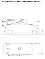
図11は、従来の全水平方位車載レーダの配置を説明する図である。
従来における運転支援レーダを搭載した車両では、図11に示すように前方、後方、左右側面に複数のレーダ装置を車体に取り付ける構成をとっていた。また、装置動作の監視方法として、特許文献1のように送信増幅装置をスイッチし、受信機の出力における発振器のノイズレベルを比較することにより、装置動作を確認していた。また、監視用信号をえるために、レーダ波の一部をアンテナにより遅延線に取り込み、遅延線に相当するビート受信信号を監視することにより、車載用FM−CWレーダ動作監視方式がある。
As shown in FIG. 11, a conventional vehicle equipped with a driving assistance radar has a configuration in which a plurality of radar devices are attached to the vehicle body on the front, rear, and left and right sides. Further, as a method for monitoring the operation of the apparatus, the operation of the apparatus is confirmed by switching the transmission amplifying apparatus as in
従来は全周囲を監視するために、図11のように、少なくとも4個以上の車載レーダを取り付けるため高コストとなっていた。前方検知レーダの場合はエンジンルーム付近に取り付けるため、前方走行車からの雪、土砂等の巻き上げや道路からの積雪、土砂によるレーダビーム変形、伝搬減衰量増加、過酷な周囲温度条件により、レーダ検知性能の大きい影響を受けるという問題があった。 Conventionally, in order to monitor the entire periphery, at least four or more on-vehicle radars are attached as shown in FIG. In the case of a forward detection radar, it is installed near the engine room, so it can be detected by rolling up snow, earth and sand from the vehicle traveling ahead, snow accumulation from the road, radar beam deformation due to earth and sand, increased propagation attenuation, and severe ambient temperature conditions. There was a problem that performance was greatly affected.
また、安全走行には、レドームに付着した雪、水膜による損失増加でレーダ性能が低下する状態、レーダ装置の故障時と無目標の状態の判別を速やかに運転者に報知することが重要であり、そのためレーダ装置を常時、正常に動作しているか否かについて監視する必要があった。例を挙げると、多くの車載レーダに採用されているFM−CW方式では、搬送波に、可変容量ダイオード(バラクタダイオード)により、周波数変調をかけるが、バラクタ回路の断線などにより、FM変調信号が断になっても無変調搬送波は依然として送信されるので、送信電力を検波し、そのレベルを監視するだけでは故障と判断できない。ハードウェアの故障態様は多数有り、それぞれに監視回路を設けると回路が複雑になり、消費電力も増大し、監視信頼度も低下する。また、実用中のレーダを車両のエンジンルーム付近の最先端部におく場合、対地からのクラッタ反射レベルを見て監視する動作監視方法がある。この方法では、路面の反射レベルを見て判断する必要があり、路面の状態が一様でなくクラッタレベルが変動する。この場合、確率が低いが反射波が低い路面状態が続き、故障と判断することがある。 For safe driving, it is important to promptly notify the driver of the status of radar performance degradation due to increased loss due to snow and water film attached to the radome, and whether the radar device has failed or not targeted. Therefore, it is necessary to monitor whether or not the radar apparatus is operating normally at all times. For example, in the FM-CW system used in many on-vehicle radars, the carrier wave is frequency-modulated by a variable capacitance diode (varactor diode), but the FM modulation signal is disconnected due to disconnection of the varactor circuit. However, since the unmodulated carrier wave is still transmitted, it cannot be determined as a failure only by detecting the transmission power and monitoring its level. There are a number of hardware failure modes, and if a monitoring circuit is provided for each, the circuit becomes complicated, the power consumption increases, and the monitoring reliability also decreases. In addition, there is an operation monitoring method in which when a radar in practical use is placed at the most advanced part near the engine room of a vehicle, the level of clutter reflection from the ground is monitored. In this method, it is necessary to judge by looking at the reflection level of the road surface, and the state of the road surface is not uniform, and the clutter level fluctuates. In this case, a road surface state with a low probability but a low reflected wave continues and may be determined as a failure.
車両の端部に取り付けられ、スカート部材を透過するレーダもあるが、この場合、スカート部の反射を見る監視も考えられる。しかし、レーダからスカート部までの距離が極端に短く、数センチのレベルを検出する必要がある。最も多く採用されているFM−CWレーダ方式の測定距離精度δRは次式で表される。
δR=(C/(4・fm・ΔF))・δfr
ただし、C:光速、fm:変調周波数、ΔF:最大周波数偏移、δfr:距離周波数精度(周波数計測方式による。FFT解析方式では、δfr=2・fm)。
Some radars are attached to the end of the vehicle and pass through the skirt member. In this case, it is possible to monitor the reflection of the skirt part. However, the distance from the radar to the skirt is extremely short, and it is necessary to detect a level of several centimeters. The measurement distance accuracy δR of the FM-CW radar system that is most often used is expressed by the following equation.
δR = (C / (4 · fm · ΔF)) · δfr
However, C: speed of light, fm: modulation frequency, ΔF: maximum frequency shift, δfr: distance frequency accuracy (according to frequency measurement method, δfr = 2 · fm in FFT analysis method).
ΔF=150MHzの精度は1m[±0.5m]となる。また、接近した2つの反射体を分離する距離分解能も1mである。多重反射で受信される場合もあるが、安定した受信レベルは得られない。 The accuracy of ΔF = 150 MHz is 1 m [± 0.5 m]. Moreover, the distance resolution which isolate | separates two reflectors which approached is also 1 m. In some cases, the signal is received with multiple reflections, but a stable reception level cannot be obtained.
また、車両の周囲の対象物を複数のレーダで検出する場合、個々のレーダすべてを監視する必要がある。
遅延線によるビート信号監視方式では、アンテナと搬送波周波数帯の高周波線路が必要であり、コスト高になる。また、レドームに付着する自然現象によるレーダ機能低下と機器性能低下と機器性能劣化が分離できない問題があった。
Further, when an object around the vehicle is detected by a plurality of radars, it is necessary to monitor all the individual radars.
In the beat signal monitoring method using a delay line, an antenna and a high-frequency line in a carrier frequency band are required, which increases costs. In addition, there is a problem that the radar function degradation due to the natural phenomenon attached to the radome, the equipment performance degradation and the equipment performance degradation cannot be separated.
本発明の課題は、車載レーダの数を減らし、かつ、車載レーダが故障しているか否かを確実に知ることのできる車載レーダ装置を提供することである。 An object of the present invention is to provide an on-vehicle radar device capable of reducing the number of on-vehicle radars and reliably knowing whether or not the on-vehicle radar is out of order.
本発明の車載レーダ装置は、車両の上部に設けられ、回転してレーダ波を送信することにより、該車両の全周囲を走査可能なレーダ手段と、該レーダ手段が測定可能な最低距離より遠く、且つ、該車両の一部であって、該レーダ手段が該車両の全周囲を走査する間に、該レーダ手段の走査範囲に入るような位置に設けられた、該レーダ波を反射する基準反射手段とを備え、該基準反射手段からの反射波を検知することにより、該レーダ手段が正常に動作しているか否かを判定することを特徴とする。 An in-vehicle radar device according to the present invention is provided at an upper part of a vehicle, and rotates to transmit a radar wave, thereby scanning the entire circumference of the vehicle, and farther than the minimum distance that the radar unit can measure. And a reference for reflecting the radar wave, which is a part of the vehicle and is provided at a position within the scanning range of the radar means while the radar means scans the entire periphery of the vehicle. And a reflection means, and by detecting a reflected wave from the reference reflection means, it is determined whether or not the radar means is operating normally.
本発明によれば、車載レーダの数を減らし、かつ、車載レーダが故障しているか否かを確実に知ることのできる車載レーダ装置を提供することができる。 ADVANTAGE OF THE INVENTION According to this invention, the number of vehicle-mounted radars can be reduced and the vehicle-mounted radar apparatus which can know reliably whether the vehicle-mounted radar is out of order can be provided.
図1〜図6は、本発明の実施形態に従った車載レーダ装置の構成を説明する図である。
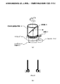
本発明の実施形態においては、図1のように車両の中央高部(天井中央)に全周囲レーダ装置10を固定し、全周囲レーダ10から離れた部分に定量電波反射物11を設ける。定量電波反射物11は、全周囲レーダ10の測定可能な最短距離より全周囲レーダ10から遠くの車体の一部に設けられる。図1においては、全周囲レーダ10と同様に、車両高部の車体の後部(天井後部)に設けられている。図1においては、定量電波反射物11の設置位置として3通り示している。車両天井の後部中央(2)のほかに、車両天井の斜め後部(1)、(3)が可能である。特に、車両天井の斜め後部(1)、(3)の場合、車両天井中央部の全周囲レーダ10からの距離を最も大きく取れるので、全周囲レーダ10から最も遠くに離すことが出来、全周囲レーダ10の検出可能な最短距離の制限を和らげることができる。定量反射体の位置は、前方でも良い。
FIGS. 1-6 is a figure explaining the structure of the vehicle-mounted radar apparatus according to embodiment of this invention.
In the embodiment of the present invention, as shown in FIG. 1, the all-
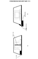
図2のように、車載レーダ装置は、下部に、送受信機と平面波を放射する平面アンテナを内蔵する収納部12が設置される。収納部12の上には、電波透過誘電体で構成された円筒13が設けられ、その中に、収納部12から上方に向かって放射されるレーダ放射ビームに対し45°の角度を持って設けられる反射板14が設けられ、これにより、水平方向にレーダ放射ビームを放射させる。反射板14は、円筒13内に内接固定され、金属めっきなどによって形成される。反射板14を回転させることにより、放射ビームを車両の水平全方向に走査することができる。
As shown in FIG. 2, the in-vehicle radar device is provided with a
図3のように、反射板14は反射板付き誘電体円筒13に取り付けられ、円筒13は角度制御が可能なパルスモータ17などで回転駆動する。円筒13は、レドームとして機能する。パルスモータ17には、歯車15が取り付けられており、円筒13を回転させる。円筒13は、ベアリングによって回転可能に固定されている。レーダユニットの収納部12は、ベアリング16の内部であって、円筒13の下部に設けられる。
As shown in FIG. 3, the reflector 14 is attached to a dielectric cylinder 13 with a reflector, and the cylinder 13 is rotationally driven by a
レーダアンテナビームが1回転する間に1回レーダ機能の監視が可能である。動作監視用の定量電波反射物11とアンテナビームの正対する角度を監視角度とすると、監視角度は予め定まっているので、監視角度のときは、図4に示すように、監視用反射体の距離のみ検出する。監視角度以外の側面や、他の方向時におけるレーダビーム時は、図5に示すように車体の外形寸法とレーダから見たレーダ検出距離関係から、レーダビーム角度ごとに有効検出距離を制限することが出来、車体の大きさに合わせて近距離の移動目標の検知を行うことができる。
The radar function can be monitored once during one rotation of the radar antenna beam. Assuming that the angle at which the quantitative
次に、レーダ動作監視について説明する。
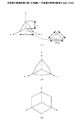
車載レーダ装置を車両上部に設置することにより、レーダビームが前方、または、後方に向いたときは、移動体が存在する位置までの距離(車長の約半分)が長く、車載レーダ装置の最短検出距離より長くなるので、近距離検出限界性能を緩和することができる。また、車載レーダ装置特に、FM−CWレーダ方式の車載レーダ装置においては、最短検出距離は、FM、AM変換雑音の影響による感度劣化のため、検出精度がよくないが、レーダ装置から定量反射体までの距離を長く出来、レーダ動作の監視用反射信号の検出に使うことができる。図1のように、レーダ装置の機能監視を行うために、車両の一部に固定レーダ反射物体(定量電波反射物11)を置き、レーダ装置10が、常時反射物体11からの信号レベルと距離を測定することによりレーダ動作の監視を行う。実用上、定量電波反射体の取り付け精度の許容値を緩和することが望ましく、定量電波反射体はレーダ波の入射角度に対して反射断面積の変化が小さいことが良い。例えば、車両の天井中央部にレーダ装置10を設置し、車両天井部の端部のレーダの感知範囲内に監視に都合よい図6に示すような反射指向性が広角な小型直交三面体コーナリフレクタ(定量電波反射物11:76GHz帯レーダバンドでは、レーダ断面積0dBsmの開口部の正三角形の一辺は6.18cm)を設置しておき、該小型コーナリフレクタの反射信号を基準に動作監視を行う。上記の0dBsmのコーナリフレクタを1m先に設置したとき、レーダ受信電力は監視に十分なレベル(送信電力0dBm、送受アンテナ利得30dBでは、−21dBm)となる。
Next, radar operation monitoring will be described.
By installing the in-vehicle radar device on the upper part of the vehicle, when the radar beam is directed forward or backward, the distance to the position where the moving body exists (about half of the vehicle length) is long and the shortest of the in-vehicle radar device Since it becomes longer than the detection distance, the short-range detection limit performance can be relaxed. In addition, in the in-vehicle radar device, particularly, in the FM-CW radar type on-vehicle radar device, the shortest detection distance is poor in detection accuracy due to sensitivity deterioration due to the influence of FM and AM conversion noise. Can be used for detecting the reflected signal for monitoring the radar operation. As shown in FIG. 1, in order to monitor the function of the radar apparatus, a fixed radar reflecting object (quantitative radio wave reflecting object 11) is placed on a part of the vehicle, and the
例えば、図6の(1)三角形三面体コーナリフレクタのレーダ反射断面積σは、
σ=4πa4/(3λ2)
で与えられる。従って、
a=4√(0.2387・σ・λ2) (m)
76.5GHzの波長0.00329mをλに代入すると、
a=4√(3.668×10⁻⁶・σ) (m)
となる。
For example, (1) the radar reflection cross section σ of the triangular trihedral corner reflector in FIG.
σ = 4πa 4 / (3λ 2 )
Given in. Therefore,
a = 4 √ (0.2387 · σ · λ 2) (m)
Substituting a wavelength of 0.0065 m for 76.5 GHz into λ,
a = 4 √ (3.668 × 10 -6 · σ) (m)
It becomes.
これより、
σ=0dBsm=1m2 a=0.04376m a/λ=11.2
σ=5dBsm=3.162m2 a=0.05835m a/λ=14.9
ここで、
XdBsm=10・log10(Y(m2)/1(m2))
である。
Than this,
σ = 0 dBsm = 1 m 2 a = 0.04376 m a / λ = 11.2
σ = 5 dBsm = 3.162 m 2 a = 0.05835 m a / λ = 14.9
here,
XdBsm = 10 · log 10 (Y (m 2 ) / 1 (m 2 ))
It is.
以上より、図6のコーナリフレクタは、数平方メートルの断面積を持つのに、開口部の一辺が6〜8cmあれば十分であることが分かる。
コーナリフレクタは、一定の反射が得られる車両の構造があれば不要である。また、反射体の形状にはこだわる必要はない。
From the above, it can be seen that the corner reflector of FIG. 6 has a cross-sectional area of several square meters, and it is sufficient that one side of the opening is 6 to 8 cm.
The corner reflector is not necessary if there is a vehicle structure that can provide constant reflection. Moreover, it is not necessary to stick to the shape of the reflector.
図7〜図10は、本発明の実施形態の動作を説明する図である。
図7は、FM−CW方式レーダ送受信装置構成と動作を説明する図である。
三角波発生回路20は、信号処理回路21からの基準信号(例、矩形波)(1)により三角波信号を発生させる。この三角波信号を高周波電圧制御発振器(VCO:Voltage Controlled Oscillator)22に入力し、三角波状の振幅に応じた高周波被周波数変調波を出力する。前記高周波被周波数変調波出力の一部を分岐し、一方を受信ミキサ23に入力し、他方は送信RFスイッチ24に入力し、送信ドライバ25により一部を分岐し、受信ミキサ27に入力し、他方は送信RFスイッチ24に入力し、送信ドライバ25により一定周期の矩形波駆動される送信スイッチ24により高周波被周波数変調波がスイッチされ送受信共用回路のハイブリッド28を介して送受共用のアンテナ29から送信される。放射された送信波は、アンテナ29から一定の距離にある動作監視を行う固定基準反射体(コーナリフレクタ)30と、レーダ搭載車以外移動体目標31によって反射され、反射波がアンテナ29に受信され、ハイブリッド28を介して送信スイッチ24と同周期し、かつ、逆相の駆動信号により開閉されるRF受信スイッチ32に入力され、ミキサ23に出力される。
7-10 is a figure explaining operation | movement of embodiment of this invention.
FIG. 7 is a diagram for explaining the configuration and operation of an FM-CW radar transmission / reception apparatus.
The triangular
ミキサ23では、反射波は前記VCO22の高周波被周波数変調波出力と混合され、周波数差分の中間周波を出力する。中間周波出力にはアンテナ29と反射体の距離に比例したビート信号が含まれる。有効周波数成分のみ通過させる中間周波帯域通過フィルタ(BPF)33を通過させた信号をミキサ27に入力し、スイッチ駆動周波数と同じ局部信号と混合し、距離ビート周波数を出力し、信号処理回路21に入力する。信号処理回路21において、ビート信号をA/D変換し(2)、デジタル化する。デジタル化ビート信号を高速フーリエ変換し(3)、ビート信号波形を周波数スペクトルに分解し、複数の距離信号に分離する。レーダビーム方向の情報であるパルスモータ34からの方向情報毎に、距離情報のビート信号をメモリに記憶する(4)。メモリ情報から目標ごとの相対速度、距離を演算する(5)。前記動作判定用の固定基準反射体からの信号成分は相対速度(ドップラシフト)のない、一定の距離信号ビート信号が得られるので、この信号強度を設定閾値と比較し(6)、レーダ機能を判定する(7)。特に、機器の劣化や、レドームに付着する雨、雪、氷、塵埃などによるレーダ波の減衰による感度低下を判定する。判定結果をレーダ機能状態の正常、異常情報を表示器35に出力する。
In the
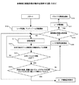
図8は、レーダ機能状態の異常判定フローチャートを示す図である。
異常検出は、レーダ機器の性能動作異常と、レーダ機器が正常でもレーダ感度が低下する気象環境により起こる。
FIG. 8 is a diagram illustrating an abnormality determination flowchart of the radar function state.
Abnormality detection occurs due to abnormal performance of radar equipment and the weather environment in which the radar sensitivity decreases even if the radar equipment is normal.
まず、ステップS10において、レーダを起動し、アンテナビームの回転を開始する。ステップS11において、回転角を設定し、ステップS12において、水平方向のビーム回転角と距離検出レベルを記録する。ステップS13において、水平ビームは一回転したか否かを判断する。ステップS13の判断がNoである場合には、ステップS11に戻る。ステップS13の判断がYesの場合には、ステップS14において、所定の角度、距離においてコーナリフレクタの検出レベルは閾値以上の検出レベルか否かを判断する。ステップS14の判断がYesの場合には、レーダ機能正常表示をすると共に、ステップS11に戻って処理を繰り返す。ステップS14の判断がNoの場合には、ステップS15において、レーダ異常回数を検出し、ステップS16において、異常検出回数は設定値か否かを判断する。ステップS16の判断がNoの場合には、ステップS11に進む。ステップS16の判断がYesの場合には、ステップS17に進んで、レーダ電源を断にし、ステップS18においてドライバに異常を通報して、処理を終了する。 First, in step S10, the radar is activated and rotation of the antenna beam is started. In step S11, the rotation angle is set, and in step S12, the horizontal beam rotation angle and the distance detection level are recorded. In step S13, it is determined whether or not the horizontal beam has rotated once. If the determination in step S13 is No, the process returns to step S11. If the determination in step S13 is Yes, in step S14, it is determined whether or not the corner reflector detection level is equal to or greater than a threshold value at a predetermined angle and distance. If the determination in step S14 is yes, the radar function is displayed normally, and the process returns to step S11 to repeat the process. If the determination in step S14 is No, the number of radar abnormalities is detected in step S15, and in step S16, it is determined whether the number of abnormal detections is a set value. If the determination in step S16 is No, the process proceeds to step S11. If the determination in step S16 is Yes, the process proceeds to step S17, the radar power supply is turned off, the driver is notified of the abnormality in step S18, and the process is terminated.
図9は、レドーム付着物除去装置の実施形態を説明する図である。
レーダ受信波は、レドームに付着する水膜で大きく減衰する。このため、図9(a)、(b)に示すように、ワイパーや高圧空気吹き付けなどで水膜を取り除く。また、寒冷地ではヒータが併用される。図9(a)では、レドームにワイパー40が付けられている。図9(a)では、1つしかワイパー40が示されていないが、360°の方位をカバーするように、ワイパー40を4つ設けるなどする。ヒータ41は、寒冷地などにおいて、雪や氷がレドームに付着した場合、これを溶かして除去するためのものである。ヒータ41は、レドームを加熱し、レドームについた氷を溶かす。図9(b)に示されるエアポンプ43とエア噴出しノズル42は、ワイパー40の代わりをするものであって、ワイパー40のように、レドームの表面をふき取るのではなく、空気を吹き付けて、付着物を吹き飛ばそうとするものである。レドーム付着物除去装置は、固定基準反射体にも適用できる。
FIG. 9 is a diagram illustrating an embodiment of a radome deposit removal apparatus.
Radar received waves are greatly attenuated by the water film adhering to the radome. For this reason, as shown in FIGS. 9A and 9B, the water film is removed by wiper or high-pressure air spraying. Moreover, a heater is used together in a cold region. In FIG. 9A, the wiper 40 is attached to the radome. Although only one wiper 40 is shown in FIG. 9A, four wipers 40 are provided so as to cover a 360 ° azimuth. The heater 41 is for melting and removing snow or ice that has adhered to the radome in a cold district or the like. The heater 41 heats the radome and melts ice attached to the radome. The air pump 43 and the air ejection nozzle 42 shown in FIG. 9B replace the wiper 40. Instead of wiping off the surface of the radome like the wiper 40, the air pump 43 and the air ejection nozzle 42 are attached by blowing air. It tries to blow off the kimono. The radome deposit removal device can also be applied to a fixed reference reflector.
図10は、レーダ機能状態の別の異常判定フローチャートを示す図である。
このレドーム付着物除去装置の作動をレーダ機能低下時に行い、レドーム付着物除去装置の作動後、基準反射体のビート信号レベルの異常設定閾値より大きくなればレドーム付着物による減衰と判断でき、基準反射体のビート信号レベルが異常設定閾値より以下で回復しなければ、レーダ送受信機の感度低下と判断できる。
FIG. 10 is a diagram illustrating another abnormality determination flowchart of the radar function state.
This radome deposit removal device is operated when the radar function is lowered, and after the radome deposit removal device is operated, if it exceeds the abnormal setting threshold of the beat signal level of the reference reflector, it can be determined that the radome deposit is attenuated, and the reference reflection If the beat signal level of the body does not recover below the abnormal setting threshold, it can be determined that the sensitivity of the radar transceiver is lowered.
ステップS20において、レーダを起動し、アンテナビームの回転を開始し、ステップS21において、回転角を設定し、ステップS22において、水平方向のビーム回転角と距離検出レベルを記録し、ステップS23において、水平ビームは1回転したか否かを判断する。ステップS23の判断がNoの場合には、ステップS21に戻る。ステップS23の判断がYesの場合には、ステップS24において、所定の角度、距離においてコーナリフレクタの検出レベルは閾値異常の検出レベルか否かを判断する。ステップS24の判断がYesの場合には、レーダ機能正常表示を行い、ステップS21に進む。ステップS24の判断がNoの場合には、ステップS25において、レーダ異常回数検出を行い、ステップS26において、異常検出回数は設定値に達したか否かを判断する。ステップS26の判断がNoの場合には、ステップS21に戻り、Yesの場合には,ステップS27に進む。ステップS27において、レドーム付着物除去装置を作動し、ステップS28において、コーナリフレクタの検出レベルは閾値以下か否かを判断する。ステップS28の判断がNoの場合には、ステップS20に進み、Yesの場合には、ステップS29に進む。ステップS29では、コーナリフレクタの検出回数が設定回数に至ったかを判断する。ステップS29の判断がNoの場合には、ステップS20に進み、Yesの場合には、ステップS30において、ドライバに異常を通報して、処理を終了する。 In step S20, the radar is started, and rotation of the antenna beam is started. In step S21, the rotation angle is set. In step S22, the horizontal beam rotation angle and the distance detection level are recorded. It is determined whether the beam has made one revolution. If the determination in step S23 is no, the process returns to step S21. If the determination in step S23 is yes, in step S24, it is determined whether or not the corner reflector detection level is a threshold abnormality detection level at a predetermined angle and distance. If the determination in step S24 is yes, the radar function normal display is performed, and the process proceeds to step S21. If the determination in step S24 is No, radar abnormality frequency detection is performed in step S25, and in step S26, it is determined whether the abnormality detection frequency has reached a set value. If the determination in step S26 is No, the process returns to step S21. If the determination is Yes, the process proceeds to step S27. In step S27, the radome deposit removing device is operated. In step S28, it is determined whether or not the detected level of the corner reflector is equal to or less than a threshold value. If the determination in step S28 is No, the process proceeds to step S20, and if Yes, the process proceeds to step S29. In step S29, it is determined whether the number of detections of the corner reflector has reached the set number. If the determination in step S29 is No, the process proceeds to step S20. If yes, in step S30, the driver is notified of the abnormality and the process is terminated.
レーダ装置の性能機能が失われる原因は、レーダ装置自体が劣化破損する場合と、装置は正常で、レドームに大量の水、雪、氷が付着し、損失が大きくなる外気気象による場合である。以上のレーダ性能劣化を判定し、レーダ性能監視を確実に行え、運転者にレーダ動作状況をいち早く報知できる。 The performance function of the radar device is lost when the radar device itself is deteriorated or damaged, or when the device is normal and a large amount of water, snow, or ice adheres to the radome, resulting in outdoor air weather that increases loss. It is possible to determine the above radar performance deterioration, reliably monitor the radar performance, and promptly notify the driver of the radar operation status.
無目標時にも信号がなくなるが、レーダ装置の故障または性能劣化と区別して、無目標時でも、レーダ性能を監視でき、いち早くレーダ性能の劣化を判別し、信頼性の高いレーダ機能状態判定が行える。 Although there is no signal even when there is no target, it is possible to monitor the radar performance even when there is no target, distinguishing it from the failure or performance degradation of the radar device, quickly determining the deterioration of the radar performance, and determining the reliable radar function status .
10 全周囲レーダ
11 定量電波反射物(コーナリフレクタ)
12 レーダアンテナ、送受信機収納部
13 円筒(電波透過誘電体円筒)
14 反射板(金属めっき反射面)
15 歯車
16 ベアリング
17 パルスモータ
20 三角波発生回路
21 信号処理回路
22 VCO
23、27 ミキサ
24 送信スイッチ
25、26 ドライバ
28 ハイブリッド回路
29 送受信アンテナ
30 固定基準反射体(コーナリフレクタ)
31 移動体目標
32 受信スイッチ
33 BPF
34 パルスモータ
35 レーダ情報表示器
40 ワイパー
41 ヒータ
42 エア噴出しノズル
43 エアポンプ
10 All-around
12 Radar antenna, transmitter / receiver housing 13 Cylinder (Radio wave transmission dielectric cylinder)
14 Reflector (Metal plating reflective surface)
15 gear 16
23, 27
31
34
Claims (5)
該レーダ手段が測定可能な最低距離より遠く、且つ、該車両の一部であって、該レーダ手段が該車両の全周囲を走査する間に、該レーダ手段の走査範囲に入るような位置に設けられた、該レーダ波を反射する基準反射手段とを備え、
該基準反射手段からの反射波を検知することにより、該レーダ手段が正常に動作しているか否かを判定することを特徴とする車載レーダ装置。 Radar means provided at the top of the vehicle and capable of scanning the entire periphery of the vehicle by rotating and transmitting radar waves;
The radar means is farther than the lowest measurable distance and is part of the vehicle so that it is within the scanning range of the radar means while the radar means scans the entire circumference of the vehicle. Provided with a reference reflecting means for reflecting the radar wave,
An on-vehicle radar device characterized by determining whether or not the radar means is operating normally by detecting a reflected wave from the reference reflecting means.
レーダ波を垂直方向に送受信するレーダユニットと、
垂直方向に送信されるレーダ波に対して45°に傾き、該レーダ波を水平方向に反射し、傾斜方向を水平方向に360°回転可能な反射板と、
該レーダ波を透過可能で、該反射板を保持し、該反射板と共に360°回転する円筒レドームと、
を備えることを特徴とする請求項1に記載の車載レーダ装置。 The radar means includes
A radar unit for transmitting and receiving radar waves in the vertical direction;
A reflector that is inclined at 45 ° with respect to the radar wave transmitted in the vertical direction, reflects the radar wave in the horizontal direction, and can rotate the inclination direction in the horizontal direction by 360 °;
A cylindrical radome capable of transmitting the radar wave, holding the reflector, and rotating 360 ° with the reflector;
The on-vehicle radar device according to claim 1, comprising:
Priority Applications (1)
| Application Number | Priority Date | Filing Date | Title |
|---|---|---|---|
| JP2004104570A JP2005291808A (en) | 2004-03-31 | 2004-03-31 | In-vehicle radar system |
Applications Claiming Priority (1)
| Application Number | Priority Date | Filing Date | Title |
|---|---|---|---|
| JP2004104570A JP2005291808A (en) | 2004-03-31 | 2004-03-31 | In-vehicle radar system |
Publications (1)
| Publication Number | Publication Date |
|---|---|
| JP2005291808A true JP2005291808A (en) | 2005-10-20 |
Family
ID=35324914
Family Applications (1)
| Application Number | Title | Priority Date | Filing Date |
|---|---|---|---|
| JP2004104570A Withdrawn JP2005291808A (en) | 2004-03-31 | 2004-03-31 | In-vehicle radar system |
Country Status (1)
| Country | Link |
|---|---|
| JP (1) | JP2005291808A (en) |
Cited By (27)
| Publication number | Priority date | Publication date | Assignee | Title |
|---|---|---|---|---|
| JP2008175713A (en) * | 2007-01-19 | 2008-07-31 | Mitsubishi Electric Corp | In-vehicle control system |
| JP2008233052A (en) * | 2007-03-23 | 2008-10-02 | Nissan Diesel Motor Co Ltd | Radar system |
| JP2008268101A (en) * | 2007-04-24 | 2008-11-06 | Kyosan Electric Mfg Co Ltd | Obstacle detection device |
| JP2010085368A (en) * | 2008-10-02 | 2010-04-15 | Ueda Japan Radio Co Ltd | Radar transmitter-receiver |
| JP2011075287A (en) * | 2009-09-29 | 2011-04-14 | Fujitsu Ltd | Traveling body |
| JP2012237724A (en) * | 2011-05-13 | 2012-12-06 | Nippon Signal Co Ltd:The | Rail road crossing obstacle detector |
| WO2015050310A1 (en) * | 2013-10-02 | 2015-04-09 | 삼성테크윈 주식회사 | Scan ladar and method for driving scan ladar |
| JP2015152485A (en) * | 2014-02-17 | 2015-08-24 | 株式会社デンソー | Distance measuring device |
| DE102016201187A1 (en) | 2015-02-16 | 2016-08-18 | Toyota Jidosha Kabushiki Kaisha | Flow regulating arrangement for a vehicle |
| EP3078987A1 (en) | 2015-04-09 | 2016-10-12 | Toyota Jidosha Kabushiki Kaisha | Arrangement structure for vicinity information detection sensor |
| US9731771B2 (en) | 2015-04-09 | 2017-08-15 | Toyota Jidosha Kabushiki Kaisha | Vehicle upper portion structure |
| DE102017205873A1 (en) | 2016-04-19 | 2017-10-19 | Toyota Jidosha Kabushiki Kaisha | An arrangement structure for a vehicle surroundings information detecting sensor |
| DE102017206550A1 (en) | 2016-04-26 | 2017-10-26 | Toyota Jidosha Kabushiki Kaisha | Mounting structure for an environmental information acquisition sensor |
| WO2018102371A1 (en) * | 2016-11-29 | 2018-06-07 | Waymo Llc | Rotating radar platform |
| CN108226881A (en) * | 2018-02-27 | 2018-06-29 | 北京环境特性研究所 | A kind of corner reflector and the automatic system for removing ice and snow |
| US10073178B2 (en) | 2015-03-24 | 2018-09-11 | Toyota Jidosha Kabushiki Kaisha | Placement structure for peripheral information detecting sensor, and self-driving vehicle |
| JP2018194564A (en) * | 2018-09-14 | 2018-12-06 | 株式会社デンソー | Distance measuring device |
| EP3486996A1 (en) * | 2017-11-20 | 2019-05-22 | Progress Rail Inspection & Information Systems S.r.l. | Radome with wiping mechanism |
| US10391981B2 (en) | 2016-12-16 | 2019-08-27 | Ford Global Technologies, Llc | Washing apparatus for a sensor enclosure |
| US10549726B2 (en) | 2017-06-22 | 2020-02-04 | Ford Global Technologies, Llc | Assembly for cleaning sensor cover and method of using the same |
| CN114355304A (en) * | 2021-12-29 | 2022-04-15 | 森思泰克河北科技有限公司 | Method, device, electronic device and storage medium for judging radar occlusion |
| JP2022091804A (en) * | 2015-04-06 | 2022-06-21 | ウェイモ エルエルシー | Long-distance maneuverable LIDAR system |
| US11458932B2 (en) | 2017-12-18 | 2022-10-04 | Ford Global Technologies, Llc | Sensor assembly with cleaning system |
| KR20230129868A (en) * | 2022-03-02 | 2023-09-11 | 주식회사 에이치엘클레무브 | In-cabin radar apparatus for vehicle and target position detection method using the same |
| WO2023188758A1 (en) * | 2022-03-29 | 2023-10-05 | パナソニックIpマネジメント株式会社 | Radar device |
| WO2024174875A1 (en) * | 2023-02-20 | 2024-08-29 | 北京罗克维尔斯科技有限公司 | Radar failure determination method, apparatus, device, medium and vehicle |
| US12362470B1 (en) | 2021-11-18 | 2025-07-15 | Waymo Llc | Systems, methods, and apparatus for determining characteristics of a radome |
-
2004
- 2004-03-31 JP JP2004104570A patent/JP2005291808A/en not_active Withdrawn
Cited By (33)
| Publication number | Priority date | Publication date | Assignee | Title |
|---|---|---|---|---|
| JP2008175713A (en) * | 2007-01-19 | 2008-07-31 | Mitsubishi Electric Corp | In-vehicle control system |
| JP2008233052A (en) * | 2007-03-23 | 2008-10-02 | Nissan Diesel Motor Co Ltd | Radar system |
| JP2008268101A (en) * | 2007-04-24 | 2008-11-06 | Kyosan Electric Mfg Co Ltd | Obstacle detection device |
| JP2010085368A (en) * | 2008-10-02 | 2010-04-15 | Ueda Japan Radio Co Ltd | Radar transmitter-receiver |
| JP2011075287A (en) * | 2009-09-29 | 2011-04-14 | Fujitsu Ltd | Traveling body |
| JP2012237724A (en) * | 2011-05-13 | 2012-12-06 | Nippon Signal Co Ltd:The | Rail road crossing obstacle detector |
| WO2015050310A1 (en) * | 2013-10-02 | 2015-04-09 | 삼성테크윈 주식회사 | Scan ladar and method for driving scan ladar |
| JP2015152485A (en) * | 2014-02-17 | 2015-08-24 | 株式会社デンソー | Distance measuring device |
| DE102016201187A1 (en) | 2015-02-16 | 2016-08-18 | Toyota Jidosha Kabushiki Kaisha | Flow regulating arrangement for a vehicle |
| US10073178B2 (en) | 2015-03-24 | 2018-09-11 | Toyota Jidosha Kabushiki Kaisha | Placement structure for peripheral information detecting sensor, and self-driving vehicle |
| JP2022091804A (en) * | 2015-04-06 | 2022-06-21 | ウェイモ エルエルシー | Long-distance maneuverable LIDAR system |
| JP7607000B2 (en) | 2015-04-06 | 2024-12-26 | ウェイモ エルエルシー | Long-range steerable LIDAR system |
| US9731771B2 (en) | 2015-04-09 | 2017-08-15 | Toyota Jidosha Kabushiki Kaisha | Vehicle upper portion structure |
| EP3078987A1 (en) | 2015-04-09 | 2016-10-12 | Toyota Jidosha Kabushiki Kaisha | Arrangement structure for vicinity information detection sensor |
| US10144424B2 (en) | 2015-04-09 | 2018-12-04 | Toyota Jidosha Kabushiki Kaisha | Arrangement structure for vicinity information detection sensor |
| US10466387B2 (en) | 2016-04-19 | 2019-11-05 | Toyota Jidosha Kabushiki Kaisha | Arrangement structure for vicinity information detection sensor |
| DE102017205873A1 (en) | 2016-04-19 | 2017-10-19 | Toyota Jidosha Kabushiki Kaisha | An arrangement structure for a vehicle surroundings information detecting sensor |
| US10458821B2 (en) | 2016-04-26 | 2019-10-29 | Toyota Jidosha Kabushiki Kaisha | Mounting structure for a peripheral information detection sensor used in a vehicle including an automatic driving system |
| DE102017206550A1 (en) | 2016-04-26 | 2017-10-26 | Toyota Jidosha Kabushiki Kaisha | Mounting structure for an environmental information acquisition sensor |
| DE102017206550B4 (en) | 2016-04-26 | 2023-06-29 | Toyota Jidosha Kabushiki Kaisha | MOUNTING STRUCTURE FOR AN AMBIENT INFORMATION DETECTION SENSOR |
| WO2018102371A1 (en) * | 2016-11-29 | 2018-06-07 | Waymo Llc | Rotating radar platform |
| US10391981B2 (en) | 2016-12-16 | 2019-08-27 | Ford Global Technologies, Llc | Washing apparatus for a sensor enclosure |
| US10549726B2 (en) | 2017-06-22 | 2020-02-04 | Ford Global Technologies, Llc | Assembly for cleaning sensor cover and method of using the same |
| EP3486996A1 (en) * | 2017-11-20 | 2019-05-22 | Progress Rail Inspection & Information Systems S.r.l. | Radome with wiping mechanism |
| US11458932B2 (en) | 2017-12-18 | 2022-10-04 | Ford Global Technologies, Llc | Sensor assembly with cleaning system |
| CN108226881A (en) * | 2018-02-27 | 2018-06-29 | 北京环境特性研究所 | A kind of corner reflector and the automatic system for removing ice and snow |
| JP2018194564A (en) * | 2018-09-14 | 2018-12-06 | 株式会社デンソー | Distance measuring device |
| US12362470B1 (en) | 2021-11-18 | 2025-07-15 | Waymo Llc | Systems, methods, and apparatus for determining characteristics of a radome |
| CN114355304A (en) * | 2021-12-29 | 2022-04-15 | 森思泰克河北科技有限公司 | Method, device, electronic device and storage medium for judging radar occlusion |
| KR20230129868A (en) * | 2022-03-02 | 2023-09-11 | 주식회사 에이치엘클레무브 | In-cabin radar apparatus for vehicle and target position detection method using the same |
| KR102714865B1 (en) | 2022-03-02 | 2024-10-11 | 주식회사 에이치엘클레무브 | In-cabin radar apparatus for vehicle and target position detection method using the same |
| WO2023188758A1 (en) * | 2022-03-29 | 2023-10-05 | パナソニックIpマネジメント株式会社 | Radar device |
| WO2024174875A1 (en) * | 2023-02-20 | 2024-08-29 | 北京罗克维尔斯科技有限公司 | Radar failure determination method, apparatus, device, medium and vehicle |
Similar Documents
| Publication | Publication Date | Title |
|---|---|---|
| JP2005291808A (en) | In-vehicle radar system | |
| US11509042B2 (en) | Radome for automotive radar patch antenna | |
| JP3587466B2 (en) | Vehicle periphery monitoring device | |
| JP3308231B2 (en) | Radar equipment | |
| US6127965A (en) | Method and apparatus for rejecting rain clutter in a radar system | |
| EP1074853B1 (en) | Vehicle radar apparatus | |
| US6124823A (en) | Radar apparatus for vehicle | |
| US7486222B2 (en) | Automotive radar device | |
| JP4045041B2 (en) | Radar apparatus and radar apparatus abnormality detection method | |
| JP4268202B2 (en) | Automotive front monitoring sensor | |
| US6278399B1 (en) | Radar apparatus and method for detecting malfunction of radar apparatus | |
| US7084761B2 (en) | Security system | |
| US20120169525A1 (en) | Fmcw radar sensor for motor vehicles | |
| EP3655797B1 (en) | Apparatus and method for detecting and correcting for blockage of an automotive radar sensor | |
| JP7174668B2 (en) | ELECTRONIC DEVICE, ELECTRONIC DEVICE CONTROL METHOD, AND ELECTRONIC DEVICE CONTROL PROGRAM | |
| US12044795B2 (en) | Electronic device, control method of electronic device, and control program of electronic device | |
| JP3244792B2 (en) | Automobile anti-collision radar with self-operation failure detection function | |
| JP3454767B2 (en) | Automotive radar equipment | |
| JP6640269B2 (en) | Electronic device, control method for electronic device, and control program for electronic device | |
| JP2001021646A (en) | On-vehicle radar apparatus | |
| JP5396052B2 (en) | Radar transceiver | |
| JP2003207561A (en) | Radar operation monitoring system | |
| JPH06168400A (en) | Radar for automobile | |
| JPH10142330A (en) | Vehicles with millimeter wave radar | |
| US20240012138A1 (en) | Radar System for Automotive Applications |
Legal Events
| Date | Code | Title | Description |
|---|---|---|---|
| A300 | Withdrawal of application because of no request for examination |
Free format text: JAPANESE INTERMEDIATE CODE: A300 Effective date: 20070605 |