EP3078825A1 - Abgaseinrichtung zur trennung von abgasfluten eines verbrennungsmotors mit mindestens zwei zylindergruppen - Google Patents
Abgaseinrichtung zur trennung von abgasfluten eines verbrennungsmotors mit mindestens zwei zylindergruppen Download PDFInfo
- Publication number
- EP3078825A1 EP3078825A1 EP16150490.7A EP16150490A EP3078825A1 EP 3078825 A1 EP3078825 A1 EP 3078825A1 EP 16150490 A EP16150490 A EP 16150490A EP 3078825 A1 EP3078825 A1 EP 3078825A1
- Authority
- EP
- European Patent Office
- Prior art keywords
- exhaust gas
- exhaust
- diaphragm
- cylinder
- cylinder group
- Prior art date
- Legal status (The legal status is an assumption and is not a legal conclusion. Google has not performed a legal analysis and makes no representation as to the accuracy of the status listed.)
- Granted
Links
Images




Classifications
-
- F—MECHANICAL ENGINEERING; LIGHTING; HEATING; WEAPONS; BLASTING
- F01—MACHINES OR ENGINES IN GENERAL; ENGINE PLANTS IN GENERAL; STEAM ENGINES
- F01N—GAS-FLOW SILENCERS OR EXHAUST APPARATUS FOR MACHINES OR ENGINES IN GENERAL; GAS-FLOW SILENCERS OR EXHAUST APPARATUS FOR INTERNAL-COMBUSTION ENGINES
- F01N13/00—Exhaust or silencing apparatus characterised by constructional features
- F01N13/08—Other arrangements or adaptations of exhaust conduits
- F01N13/10—Other arrangements or adaptations of exhaust conduits of exhaust manifolds
- F01N13/107—More than one exhaust manifold or exhaust collector
-
- F—MECHANICAL ENGINEERING; LIGHTING; HEATING; WEAPONS; BLASTING
- F02—COMBUSTION ENGINES; HOT-GAS OR COMBUSTION-PRODUCT ENGINE PLANTS
- F02D—CONTROLLING COMBUSTION ENGINES
- F02D9/00—Controlling engines by throttling air or fuel-and-air induction conduits or exhaust conduits
- F02D9/08—Throttle valves specially adapted therefor; Arrangements of such valves in conduits
-
- F—MECHANICAL ENGINEERING; LIGHTING; HEATING; WEAPONS; BLASTING
- F01—MACHINES OR ENGINES IN GENERAL; ENGINE PLANTS IN GENERAL; STEAM ENGINES
- F01N—GAS-FLOW SILENCERS OR EXHAUST APPARATUS FOR MACHINES OR ENGINES IN GENERAL; GAS-FLOW SILENCERS OR EXHAUST APPARATUS FOR INTERNAL-COMBUSTION ENGINES
- F01N13/00—Exhaust or silencing apparatus characterised by constructional features
- F01N13/08—Other arrangements or adaptations of exhaust conduits
-
- F—MECHANICAL ENGINEERING; LIGHTING; HEATING; WEAPONS; BLASTING
- F01—MACHINES OR ENGINES IN GENERAL; ENGINE PLANTS IN GENERAL; STEAM ENGINES
- F01N—GAS-FLOW SILENCERS OR EXHAUST APPARATUS FOR MACHINES OR ENGINES IN GENERAL; GAS-FLOW SILENCERS OR EXHAUST APPARATUS FOR INTERNAL-COMBUSTION ENGINES
- F01N13/00—Exhaust or silencing apparatus characterised by constructional features
- F01N13/08—Other arrangements or adaptations of exhaust conduits
- F01N13/10—Other arrangements or adaptations of exhaust conduits of exhaust manifolds
-
- F—MECHANICAL ENGINEERING; LIGHTING; HEATING; WEAPONS; BLASTING
- F02—COMBUSTION ENGINES; HOT-GAS OR COMBUSTION-PRODUCT ENGINE PLANTS
- F02B—INTERNAL-COMBUSTION PISTON ENGINES; COMBUSTION ENGINES IN GENERAL
- F02B37/00—Engines characterised by provision of pumps driven at least for part of the time by exhaust
-
- F—MECHANICAL ENGINEERING; LIGHTING; HEATING; WEAPONS; BLASTING
- F02—COMBUSTION ENGINES; HOT-GAS OR COMBUSTION-PRODUCT ENGINE PLANTS
- F02D—CONTROLLING COMBUSTION ENGINES
- F02D9/00—Controlling engines by throttling air or fuel-and-air induction conduits or exhaust conduits
- F02D9/08—Throttle valves specially adapted therefor; Arrangements of such valves in conduits
- F02D9/12—Throttle valves specially adapted therefor; Arrangements of such valves in conduits having slidably-mounted valve members; having valve members movable longitudinally of conduit
- F02D9/14—Throttle valves specially adapted therefor; Arrangements of such valves in conduits having slidably-mounted valve members; having valve members movable longitudinally of conduit the members being slidable transversely of conduit
-
- F—MECHANICAL ENGINEERING; LIGHTING; HEATING; WEAPONS; BLASTING
- F02—COMBUSTION ENGINES; HOT-GAS OR COMBUSTION-PRODUCT ENGINE PLANTS
- F02D—CONTROLLING COMBUSTION ENGINES
- F02D9/00—Controlling engines by throttling air or fuel-and-air induction conduits or exhaust conduits
- F02D9/08—Throttle valves specially adapted therefor; Arrangements of such valves in conduits
- F02D9/12—Throttle valves specially adapted therefor; Arrangements of such valves in conduits having slidably-mounted valve members; having valve members movable longitudinally of conduit
- F02D9/16—Throttle valves specially adapted therefor; Arrangements of such valves in conduits having slidably-mounted valve members; having valve members movable longitudinally of conduit the members being rotatable
-
- F—MECHANICAL ENGINEERING; LIGHTING; HEATING; WEAPONS; BLASTING
- F01—MACHINES OR ENGINES IN GENERAL; ENGINE PLANTS IN GENERAL; STEAM ENGINES
- F01N—GAS-FLOW SILENCERS OR EXHAUST APPARATUS FOR MACHINES OR ENGINES IN GENERAL; GAS-FLOW SILENCERS OR EXHAUST APPARATUS FOR INTERNAL-COMBUSTION ENGINES
- F01N13/00—Exhaust or silencing apparatus characterised by constructional features
- F01N13/08—Other arrangements or adaptations of exhaust conduits
- F01N13/10—Other arrangements or adaptations of exhaust conduits of exhaust manifolds
- F01N13/105—Other arrangements or adaptations of exhaust conduits of exhaust manifolds having the form of a chamber directly connected to the cylinder head, e.g. without having tubes connected between cylinder head and chamber
-
- F—MECHANICAL ENGINEERING; LIGHTING; HEATING; WEAPONS; BLASTING
- F01—MACHINES OR ENGINES IN GENERAL; ENGINE PLANTS IN GENERAL; STEAM ENGINES
- F01N—GAS-FLOW SILENCERS OR EXHAUST APPARATUS FOR MACHINES OR ENGINES IN GENERAL; GAS-FLOW SILENCERS OR EXHAUST APPARATUS FOR INTERNAL-COMBUSTION ENGINES
- F01N2240/00—Combination or association of two or more different exhaust treating devices, or of at least one such device with an auxiliary device, not covered by indexing codes F01N2230/00 or F01N2250/00, one of the devices being
- F01N2240/14—Combination or association of two or more different exhaust treating devices, or of at least one such device with an auxiliary device, not covered by indexing codes F01N2230/00 or F01N2250/00, one of the devices being a fuel burner
-
- F—MECHANICAL ENGINEERING; LIGHTING; HEATING; WEAPONS; BLASTING
- F01—MACHINES OR ENGINES IN GENERAL; ENGINE PLANTS IN GENERAL; STEAM ENGINES
- F01N—GAS-FLOW SILENCERS OR EXHAUST APPARATUS FOR MACHINES OR ENGINES IN GENERAL; GAS-FLOW SILENCERS OR EXHAUST APPARATUS FOR INTERNAL-COMBUSTION ENGINES
- F01N2240/00—Combination or association of two or more different exhaust treating devices, or of at least one such device with an auxiliary device, not covered by indexing codes F01N2230/00 or F01N2250/00, one of the devices being
- F01N2240/36—Combination or association of two or more different exhaust treating devices, or of at least one such device with an auxiliary device, not covered by indexing codes F01N2230/00 or F01N2250/00, one of the devices being an exhaust flap
-
- F—MECHANICAL ENGINEERING; LIGHTING; HEATING; WEAPONS; BLASTING
- F01—MACHINES OR ENGINES IN GENERAL; ENGINE PLANTS IN GENERAL; STEAM ENGINES
- F01N—GAS-FLOW SILENCERS OR EXHAUST APPARATUS FOR MACHINES OR ENGINES IN GENERAL; GAS-FLOW SILENCERS OR EXHAUST APPARATUS FOR INTERNAL-COMBUSTION ENGINES
- F01N2290/00—Movable parts or members in exhaust systems for other than for control purposes
- F01N2290/02—Movable parts or members in exhaust systems for other than for control purposes with continuous rotary movement
-
- F—MECHANICAL ENGINEERING; LIGHTING; HEATING; WEAPONS; BLASTING
- F01—MACHINES OR ENGINES IN GENERAL; ENGINE PLANTS IN GENERAL; STEAM ENGINES
- F01N—GAS-FLOW SILENCERS OR EXHAUST APPARATUS FOR MACHINES OR ENGINES IN GENERAL; GAS-FLOW SILENCERS OR EXHAUST APPARATUS FOR INTERNAL-COMBUSTION ENGINES
- F01N2290/00—Movable parts or members in exhaust systems for other than for control purposes
- F01N2290/02—Movable parts or members in exhaust systems for other than for control purposes with continuous rotary movement
- F01N2290/06—Movable parts or members in exhaust systems for other than for control purposes with continuous rotary movement driven by auxiliary drive
-
- F—MECHANICAL ENGINEERING; LIGHTING; HEATING; WEAPONS; BLASTING
- F01—MACHINES OR ENGINES IN GENERAL; ENGINE PLANTS IN GENERAL; STEAM ENGINES
- F01N—GAS-FLOW SILENCERS OR EXHAUST APPARATUS FOR MACHINES OR ENGINES IN GENERAL; GAS-FLOW SILENCERS OR EXHAUST APPARATUS FOR INTERNAL-COMBUSTION ENGINES
- F01N2290/00—Movable parts or members in exhaust systems for other than for control purposes
- F01N2290/08—Movable parts or members in exhaust systems for other than for control purposes with oscillating or vibrating movement
-
- F—MECHANICAL ENGINEERING; LIGHTING; HEATING; WEAPONS; BLASTING
- F02—COMBUSTION ENGINES; HOT-GAS OR COMBUSTION-PRODUCT ENGINE PLANTS
- F02D—CONTROLLING COMBUSTION ENGINES
- F02D23/00—Controlling engines characterised by their being supercharged
-
- Y—GENERAL TAGGING OF NEW TECHNOLOGICAL DEVELOPMENTS; GENERAL TAGGING OF CROSS-SECTIONAL TECHNOLOGIES SPANNING OVER SEVERAL SECTIONS OF THE IPC; TECHNICAL SUBJECTS COVERED BY FORMER USPC CROSS-REFERENCE ART COLLECTIONS [XRACs] AND DIGESTS
- Y02—TECHNOLOGIES OR APPLICATIONS FOR MITIGATION OR ADAPTATION AGAINST CLIMATE CHANGE
- Y02T—CLIMATE CHANGE MITIGATION TECHNOLOGIES RELATED TO TRANSPORTATION
- Y02T10/00—Road transport of goods or passengers
- Y02T10/10—Internal combustion engine [ICE] based vehicles
- Y02T10/12—Improving ICE efficiencies
Definitions
- the invention relates to an exhaust device for separating exhaust gas flows of an internal combustion engine with at least two cylinder groups, with the features of the preamble of claim 1.
- the invention relates to a method having the features of the preamble of claim 11.
- the internal combustion engine has at least two cylinder groups, wherein each cylinder group is assigned an exhaust gas flow.
- the exhaust gas flows open into a switching device in the form of a diaphragm arrangement, wherein by means of the diaphragm arrangement, the exhaust gas flows are alternately connectable to different, output-side exhaust gas lines.
- the output-side exhaust gas lines are each assigned to one of the exhaust gas flows.
- the exhaust gas flows or exhaust gas strands are formed by respective circular sector-shaped tubes, which together cover a circular cross-section.
- the diaphragm arrangement has a rotatable diaphragm disk with sector-shaped areas for covering or releasing the pipes.
- the diaphragm assembly is mechanically driven by means of a rotary drive by means of a rack, a worm or a gear.
- the output-side exhaust gas lines each have crosstalk points with different spacing in the flow direction to the diaphragm arrangement.
- the output-side exhaust gas lines each have a catalytic converter.
- an exhaust device in the form of an exhaust flap assembly is known.
- the exhaust flap arrangement is arranged in a double-flow exhaust gas arrangement with a first exhaust gas line and with a second exhaust gas line of an internal combustion engine.
- the exhaust flap assembly now has exhaust valves, wherein the one exhaust valve in the first exhaust line and the other exhaust valve is arranged in the second exhaust line.
- the two exhaust flaps are connected by a driver.
- the two exhaust flaps are arranged rotated by 90 ° against each other.
- the generic exhaust system is not yet optimally formed.
- the crosstalk between the exhaust gas flows of the different cylinder groups can lead to an increased residual gas content and thus to an increased tendency to knock, especially in full load operation. As a result, the performance of the internal combustion engine can be limited.
- the invention is therefore based on the object to prevent crosstalk between the exhaust gas flows of different cylinder groups.
- the exhaust gas flows are alternately connectable to the output side exhaust line.
- adjacent cylinders are assigned to different cylinder groups and thus different exhaust gas flows.
- the diaphragm arrangement is operated in dependence on exhaust valve control times of the cylinder groups.
- the currently exhaust gas-discharging cylinder group is in each case connected via the diaphragm arrangement with the output-side exhaust gas flow.
- the cylinder group which does not discharge exhaust gas or, if appropriate, the other cylinder groups which do not emit exhaust gas are separated from the output-side exhaust gas line by means of the diaphragm arrangement.
- the diaphragm arrangement is controlled and / or regulated accordingly.
- the diaphragm assembly alternately releases or blocks the exhaust gas flows of the cylinder groups at certain times to prevent crosstalk. It is preferably only one of the exhaust gas flows connected to one of the exhaust gas lines, which has the advantage that all other exhaust gas flows are protected against crosstalk.
- the internal combustion engine has two cylinder groups.
- the internal combustion engine can be designed in particular as a 4-cylinder engine.
- the internal combustion engine may include a cylinder head with an integrated exhaust manifold, the exhaust manifold forming the exhaust gas flows.
- the diaphragm assembly is disposed downstream of the exhaust manifold.
- the engine has more than two cylinder groups.
- the cylinders associated with the respective cylinder group have different exhaust valve timing.
- the opening times of the diaphragm arrangement depend on the exhaust valve control times of the cylinders.
- the changing connection of the exhaust gas flows with the at least one exhaust gas line takes place in particular as a function of the crankshaft angle.
- the changing connection of the exhaust gas flows with the exhaust gas line takes place in particular a certain crankshaft angle after the opening of the exhaust valve of the exhaust gas expelling cylinder of the associated cylinder group.
- the diaphragm assembly thereby opens the connection to the exhaust gas line, preferably offset by a certain crankshaft angle after the exhaust valve of the exhaust gas discharging cylinder has been opened.
- This particular crankshaft angle may also be referred to as an offset, and depends in particular on the duration required by the exhaust pulse from the exhaust valve to the orifice assembly.
- a 4-cylinder engine with 180 degrees of the crankshaft angle (° CA) Zündabstand the opening duration is 180 ° CA each.
- a 4-cylinder engine has first, second, third and fourth cylinders.
- the firing order can be 1-3-4-2.
- adjacent cylinders are assigned to different cylinder groups.
- the first and fourth cylinders form a first cylinder group and the second and third cylinders form a second cylinder group.
- the first cylinder group with the first and the fourth cylinder is assigned a first exhaust gas flow.
- the second and third cylinders form a second cylinder group.
- the second cylinder group is associated with a second exhaust gas flow.
- the first exhaust gas flow through the diaphragm arrangement is opened and thus connected to the corresponding output-side exhaust gas line.
- the second exhaust gas flow is blocked by the diaphragm arrangement and thus the second exhaust gas flow is separated from the output side exhaust gas flow.
- the exhaust gas of the first cylinder flows now through the first exhaust gas flow and through the diaphragm arrangement in the exhaust system.
- the fact that the diaphragm arrangement blocks the second exhaust gas flow at the same time prevents the exhaust gas of the exhausting, first cylinder from entering the second exhaust gas flow. As a result, a crosstalk between the first cylinder group and the second cylinder group is prevented.
- the third cylinder will subsequently start the pushing-out process.
- the second exhaust gas flow is opened and the first exhaust gas flow is closed by the diaphragm arrangement.
- the first exhaust gas flow of the first and fourth cylinders is closed by the diaphragm arrangement. It can thus be prevented that the exhaust gas of an exhaust gas-expelling cylinder is pushed back into the exhaust-gas ejecting cylinder thereafter.
- the residual gas content and thus a tendency to knock are reduced.
- the performance of the internal combustion engine can be increased. Even with a correspondingly long outlet pulse crosstalk can be prevented.
- the performance of the internal combustion engine can be significantly increased.
- the performance of the internal combustion engine is further increased by an exhaust gas turbocharger.
- a turbine of the exhaust gas turbocharger is arranged downstream of the diaphragm arrangement.
- the diaphragm arrangement has a rotating diaphragm disc.
- This diaphragm disk preferably has circular-ring-segment-shaped slots extending in each case over a partial circumference, which slots are each assigned to one of the exhaust-gas floods.
- the slots are arranged at different radii of the rotating disk. This allows a great freedom of design and thus large degrees of freedom in the design of the opening duration. It is conceivable that the diaphragm disc with a crankshaft speed or a speed proportional to the crankshaft speed, for example, the camshaft speed is rotated and driven accordingly. In particular, when the aperture disc rotates at crankshaft speed, the slots extend through an angle of 180 degrees. When the disc rotates at half the speed of rotation of the camshaft speed, the slots preferably extend through an angle of 90 degrees. Adjacent slots are offset by 90 ° and 180 °, respectively, and arranged at different radii.
- a further embodiment of the diaphragm arrangement has a translationally movable closure means which enables a translatory movement for closing and releasing the exhaust gas floods.
- a closure means for example, two sheets can be used, which perform a translational movement.
- the movement of the Closure means is controlled for example by a cam.
- the closure means interacts with the cam.
- the closure means is moved translationally or rotationally by a servo drive.
- FIG. 1 and 2 is very schematically an exhaust device 1 for the separation of exhaust gas flows 2, 3 of an internal combustion engine 4 shown.
- the internal combustion engine 4 has a cylinder head 5 with an exhaust manifold (not shown in detail).
- the internal combustion engine 4 may for example comprise four cylinders, namely a first, a second, a third and a fourth cylinder. The exhaust gas of the first and of the fourth cylinder are thereby discharged through the exhaust gas flow 2 and the exhaust gas of the second and third cylinders are discharged through the exhaust gas flow 3.
- the internal combustion engine 4 thus has two cylinder groups, namely a first cylinder group with the first and the fourth cylinder and a second cylinder group with the second and third cylinders.
- the internal combustion engine 4 has more than two cylinder groups, for example three or four cylinder groups.
- Each cylinder group has at least one cylinder.
- the cylinder groups preferably each have two cylinders.
- Each cylinder group is assigned an exhaust gas flow 2, 3.
- the exhaust gas flows 2, 3 form the entrance of a diaphragm arrangement 6.
- the two output-side exhaust gas lines 7, 8 open into a common exhaust gas line 9.
- a turbine 10 of an exhaust gas turbocharger is arranged downstream of the diaphragm arrangement 6, a turbine 10 of an exhaust gas turbocharger is arranged.
- the exhaust line 9 is fed to the turbine 10.
- the exhaust gas flows 2, 3 are alternately connectable to one of the output-side exhaust gas lines 7, 8 and thereby also to the exhaust gas line 9.
- the exhaust gas flow 2 and the exhaust gas line 7 are arranged in alignment with each other.
- the exhaust gas flow 3 and the exhaust gas line 8 are also arranged in alignment with each other.
- the diaphragm assembly 6 each have a rotating diaphragm disc 11, 12.
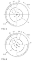
- the diaphragm disc 11 (see. Fig. 3 ) has two slots 13, 14, which are arranged in a circle segment in each case at the same radial distance from the axis of rotation 15 as the exhaust gas flow 2 or the exhaust gas flow 3.
- the slots 13, 14 each extend over a rotation angle of 180 ° degrees.
- the slots 13, 14 are arranged offset from one another in such a way that in each case only one of the exhaust gas flows 2, 3 is connected to one of the exhaust gas strands 7, 8.
- the slots 13, 14 are here offset by 180 ° to each other.
- aperture plate 12 has two slots 16 and two slots 17.
- the slots 16 are associated with the exhaust gas flow 2 and the exhaust line 7 and arranged radially on the outside.
- the radially inner slots 17 are arranged in the radial height of the exhaust gas flow 3 and the exhaust line 8, respectively.
- the slots 16, 17 are formed on the orifice plate 12, so that only one of the exhaust gas flows 2, 3 is connected to the corresponding exhaust line 7, 8, and the other exhaust gas lines 7, 8 are blocked by the exhaust gas floods 2, 3 ,
- the slots 16, 17 each extend over 90 degrees of the angular extent.
- the slots 16, 17 are alternately spaced 90 degrees apart.
- the two slots 16 are each arranged at 180 degrees spaced from each other, the two slots 17 also arranged spaced apart by 180 degrees.
- the diaphragm arrangement 6 is operable in dependence on the exhaust valve control times of the cylinders, wherein the exhaust gas discharging cylinder group is connected via the diaphragm arrangement 6 to the outlet side exhaust gas flow 7, 8, whereby the cylinder group not exhaust gas exhausting is separated from the output side exhaust gas train 7, 8 by means of the diaphragm arrangement 6.
- the diaphragm arrangement 6 can be operated as a function of exhaust valve control times of the cylinder groups in that the diaphragm disk rotates at a rotational speed proportional to the crankshaft or camshaft rotational speed.
- aperture plate 11 is driven at the speed of the crankshaft.
- aperture plate 12 is driven at the speed of the camshaft.
- the closing of the exhaust gas floods 2, 3 takes place according to the firing order, so that the in Fig. 2 indicated exhaust port 18 does not pass through the exhaust line 8 back into the exhaust gas flow 3.
- the exhaust stroke 19 in the second cylinder group is prevented by the diaphragm assembly 6 from returning to the exhaust gas flow 2.
- Fig. 6 is more schematically the aperture throttle function 20 and 21 shown.
- the second throttle function 21 indicates that the diaphragm assembly 6 for the Exhaust gas 3 is open and thus the exhaust port 19 in the exhaust line 8, but can not get back through the exhaust line 7 into the exhaust gas flow 2.
- the throttle function 21 falls to the value "0" and the aperture throttle function 20 corresponding to the value "1", so that the exhaust port 18 through the exhaust gas flow 2 into the exhaust line 7, but not back through the exhaust line. 8 can get into the exhaust gas 3.
- Vertically represented flanks (unspecified) are indicated only schematically. The slope of the flanks depends on the configuration of the slots 13, 14, 16, 17 and the configuration of the exhaust gas floods 2, 3 in the region of the diaphragm arrangement 6.
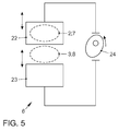
- the diaphragm assembly 6 by one or more translationally movable closure means 22, 23 may be formed.
- the closure means 22, 23 are displaced translationally, so that in each case one of the closure means 22, 23 obscures one of the exhaust gas flows 2, 3 and thus separates the corresponding exhaust gas flow 2, 3 from the corresponding exhaust gas line 7, 8.
- the other exhaust gas flow 3, 2 is correspondingly connected to the exhaust gas line 8, 7.
- the control of the closure means 2, 3 can be effected by means of a cam 24.
- the cam 24 is rotated.
- the cam 24 may, for example, rotate at crankshaft speed.
- Fig. 7 is a valve opening timing 25 of the intake valves (not shown) plotted against the rotational speed of the engine 4. Further, a valve closing timing 26 of the exhaust valve is shown.
- a shutter control 27 of the shutter assembly 6 is offset by a preferably constant crankshaft angle or offset to the valve closing timing 26 of the exhaust valve. The offset between the shutter control 27 and the valve closing timing 26 corresponds to the Essentially the time that the exhaust pulses 18, 19 on the way from the exhaust valve to the diaphragm assembly 6 need.
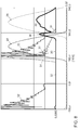
- a stroke 28 of the exhaust valve and a lift 29 of the intake valve are plotted above the crankshaft angle.
- the exhaust valve 28 is opened shortly before 180 ° CA and closed shortly after 360 ° KW.
- Good to see is that after opening the inlet valve 29, the mass flow 30 initially increases, then drops again a little and then rises again. The waste is not so strong that the flow direction of the mass flow 30 would be reversed.
- This is achieved in that the diaphragm assembly 6 prevents penetration of the exhaust gas expelled toward the end of the stroke 28 of the exhaust valve into the corresponding exhaust gas flow 2, 3.
- the mass flow 31 of the exhaust valve shown.
- the mass flow 32 of the first exhaust gas flow 2 through the diaphragm assembly 6 is also shown. It can be clearly seen that the mass flow 32 in the ranges 0 ° CA to 180 ° CA and 360 ° CA to 540 ° CA is equal to zero, since here the diaphragm arrangement 6 obstructs the exhaust gas flow 2.
- Fig. 9 is a torque 33 of an internal combustion engine 4 without an inventive exhaust device 1 and a torque 34 of an internal combustion engine 4 with a downstream exhaust device 1 according to the invention shown. It can be clearly seen that the torque of the internal combustion engine 4 with the exhaust device 1 according to the invention is higher than the torque 33, in particular in the range up to 4,000 revolutions per minute.
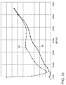
- Fig. 10 is a residual gas content 35 and a residual gas content 36 plotted in each one of the cylinder above the speed.
- the residual gas content 35 is for an internal combustion engine without an inventive exhaust device 1 and the residual gas content 36 is shown for an internal combustion engine with a downstream exhaust device 1 according to the invention. It can be clearly seen that the residual gas content of the internal combustion engine with the downstream exhaust device 1 is lower than the residual gas content 35.
- the inventive exhaust device 1 makes it easier to push out the exhaust fumes 18, 19, and the exhaust counterpressure decreases. As a result, the residual gas content can be reduced, which leads to a corresponding increase in torque.
Landscapes
- Engineering & Computer Science (AREA)
- Chemical & Material Sciences (AREA)
- Combustion & Propulsion (AREA)
- Mechanical Engineering (AREA)
- General Engineering & Computer Science (AREA)
- Supercharger (AREA)
- Exhaust Silencers (AREA)
- Exhaust Gas After Treatment (AREA)
Abstract
Description
- Die Erfindung betrifft eine Abgaseinrichtung zur Trennung von Abgasfluten eines Verbrennungsmotors mit mindestens zwei Zylindergruppen, mit den Merkmalen des Oberbegriffes des Patentanspruches 1.
- Ferner betrifft die Erfindung ein Verfahren mit den Merkmalen des Oberbegriffes des Patentanspruches 11.
- Aus der gattungsbildenden
DE 102 36 732 A1 ist eine mehrflutige Abgaseinrichtung zur Trennung von Abgasfluten eines Verbrennungsmotors bekannt. Der Verbrennungsmotor weist mindestens zwei Zylindergruppen auf, wobei jeder Zylindergruppe eine Abgasflut zugeordnet ist. Die Abgasfluten münden in eine Schalteinrichtung in Form einer Blendenanordnung, wobei mittels der Blendenanordnung die Abgasfluten wechselweise mit unterschiedlichen, ausgangsseitigen Abgassträngen verbindbar sind. Die ausgangsseitigen Abgasstränge sind jeweils einer der Abgasfluten zugeordnet. Die Abgasfluten beziehungsweise Abgasstränge sind durch jeweils kreissektorförmige Rohre gebildet, die gemeinsam einen kreisförmigen Querschnitt überdecken. Die Blendenanordnung weist eine drehbare Blendenscheibe mit kreissektorförmigen Bereichen zum Abdecken beziehungsweise Freigeben der Rohre auf. Die Blendenanordnung ist mittels eines Drehantriebes mechanisch mittels einer Zahnstange, einer Schnecke oder eines Zahnrades antreibbar. Die ausgangsseitigen Abgasstränge weisen jeweils Übersprechstellen mit unterschiedlichem Abstand in Strömungsrichtung zur Blendenanordnung auf. Hierdurch ist ein Umschalten des Abgasstromes zwischen den ausgangsseitigen Abgassträngen mit unterschiedlichen Übersprechstellen schaltbar und demgemäß soll eine Optimierung im Hinblick auf die unterschiedlichen Betriebspunkte der Brennkraftmaschine erfolgen. Gemäß eines weiteren Ausführungsbeispiels weisen die ausgangsseitigen Abgasstränge jeweils einen Katalysator auf. Durch ein Umschalten mittels der Blendenanordnung können die Katalysatoren wechselnd beaufschlagt werden. Die Katalysatoren sind in Strömungsrichtung unterschiedlich weit von der Blendenanordnung beabstandet, so dass durch ein Umschalten ein brennkraftmaschinennaher- und/oder ein brennkraftmaschinenferner Katalysator beaufschlagt werden kann. - Aus der
DE 44 26 028 C1 ist eine Abgaseinrichtung in Form einer Abgasklappenanordnung bekannt. Die Abgasklappenanordnung ist in einer zweiflutigen Abgasstranganordnung mit einem ersten Abgasstrang und mit einem zweiten Abgasstrang einer Brennkraftmaschine angeordnet. Die Abgasklappenanordnung weist nun Abgasklappen auf, wobei die eine Abgasklappe im ersten Abgasstrang und die andere Abgasklappe im zweiten Abgasstrang angeordnet ist. Die beiden Abgasklappen sind durch einen Mitnehmer miteinander verbunden. Die beiden Abgasklappen sind um 90° Grad gegeneinander verdreht angeordnet. - Die gattungsbildende Abgaseinrichtung ist noch nicht optimal ausgebildet. Das Übersprechen zwischen den Abgasfluten der unterschiedlichen Zylindergruppen kann zu einem erhöhten Restgasgehalt und damit zu einer erhöhten Klopfneigung insbesondere im Volllastbetrieb führen. Hierdurch kann die Leistungsfähigkeit des Verbrennungsmotors begrenzt sein.
- Der Erfindung liegt daher die Aufgabe zugrunde, ein Übersprechen zwischen den Abgasfluten der unterschiedlichen Zylindergruppen zu verhindern.
- Diese der Erfindung zugrunde liegende Aufgabe wird nun durch eine Abgaseinrichtung mit den Merkmalen des Patentanspruches 1 gelöst. Die Erfindung wird ferner durch ein Verfahren mit den Merkmalen des Patentanspruches 10 gelöst.
- Mittels der Blendenanordnung sind die Abgasfluten wechselweise mit dem ausgangsseitigen Abgasstrang verbindbar. In einer Zündfolge benachbarte Zylinder sind unterschiedlichen Zylindergruppen und damit unterschiedlichen Abgasfluten zugeordnet. Die Blendenanordnung wird dabei in Abhängigkeit von Auslassventilsteuerzeiten der Zylindergruppen betrieben. Die aktuell abgasausschiebende Zylindergruppe ist dabei jeweils über die Blendenanordnung mit dem ausgangsseitigen Abgasstrom verbunden. Die nicht abgasausschiebende Zylindergruppe oder gegebenenfalls die weiteren, nicht abgasausschiebenden Zylindergruppen sind mittels der Blendenanordnung von dem ausgangsseitigen Abgasstrang getrennt. Die Blendenanordnung wird entsprechend gesteuert und/oder geregelt. Die Blendenanordnung gibt die Abgasfluten der Zylindergruppen wechselweise zu bestimmten Zeitpunkten frei oder versperrt diese, um ein Übersprechen zu verhindern. Es ist vorzugsweise jeweils nur eine der Abgasfluten mit einem der Abgasstränge verbunden, was den Vorteil hat, dass alle anderen Abgasfluten vor einem Übersprechen geschützt sind.
- In bevorzugter Ausgestaltung weist der Verbrennungsmotor zwei Zylindergruppen auf. Der Verbrennungsmotor kann insbesondere als 4-Zylinder-Motor ausgebildet sein. Der Verbrennungsmotor kann einen Zylinderkopf mit einem integrierten Abgaskrümmer aufweisen, wobei der Abgaskrümmer die Abgasfluten bildet. Die Blendenanordnung ist stromabwärts des Abgaskrümmers angeordnet. In anderen Ausgestaltungen weist der Verbrennungsmotor mehr als zwei Zylindergruppen auf. Die der jeweiligen Zylindergruppe zugeordneten Zylinder weisen unterschiedliche Auslassventilsteuerzeiten auf.
- Die Öffnungszeitpunkte der Blendenanordnung richten sich nach den Auslassventilsteuerzeiten der Zylinder. Die wechselnde Verbindung der Abgasfluten mit dem mindestens einen Abgasstrang erfolgt insbesondere in Abhängigkeit des Kurbelwellenwinkels. Die wechselnde Verbindung der Abgasfluten mit den Abgasstrang erfolgt insbesondere einen bestimmten Kurbelwellenwinkel nach dem Öffnen des Auslassventils des abgasausschiebenden Zylinders der zugehörigen Zylindergruppe. Die Blendenanordnung öffnet dabei die Verbindung zu dem Abgasstrang vorzugsweise um einen bestimmten Kurbelwellenwinkel versetzt nachdem das Auslassventil des abgasausschiebenden Zylinders geöffnet worden ist. Dieser bestimmte Kurbelwellenwinkel kann auch als Offset bezeichnet werden und hängt insbesondere von der Dauer ab, die der Auslassimpuls von dem Auslassventil bis zu Blendenanordnung benötigt.
- Bei einem 4-Zylinder-Motor mit 180 Grad des Kurbelwellenwinkel (°KW) Zündabstand beträgt die Öffnungsdauer jeweils 180 °KW. Ein 4-Zylinder-Motor weist beispielsweise einen ersten, zweiten, dritten und vierten Zylinder auf. Die Zündfolge kann 1-3-4-2 betragen. In der Zündfolge benachbarte Zylinder sind unterschiedlichen Zylindergruppen zugeordnet. Der erste und der vierte Zylinder bilden eine erste Zylindergruppe und der zweite und dritte Zylinder bilden eine zweite Zylindergruppe. Der ersten Zylindergruppe mit dem ersten und dem vierten Zylinder ist dabei eine erste Abgasflut zugeordnet. Der zweite und dritte Zylinder bilden eine zweite Zylindergruppe ist. Der zweiten Zylindergruppe ist eine zweite Abgasflut zugeordnet. Diese getrennten Abgasfluten bilden nun jeweils den Eingang der Blendenanordnung. Hinter der Blendenanordnung werden die Abgasfluten zunächst in jeweils einen separaten Abgasstrang und danach in einen gemeinsamen Abgasstrang zusammengeführt.
- Wenn nun der erste Zylinder ausschiebt, ist die erste Abgasflut durch die Blendenanordnung geöffnet und somit mit dem entsprechenden ausgangsseitigen Abgasstrang verbunden. Die zweite Abgasflut ist durch die Blendenanordnung versperrt und somit ist die zweite Abgasflut von dem ausgangsseitigen Abgasstrang getrennt. Das Abgas des ersten Zylinders strömt nun durch die erste Abgasflut und durch die Blendenanordnung in den Abgasstrang. Dadurch, dass die Blendenanordnung die zweite Abgasflut gleichzeitig sperrt, ist verhindert, dass das Abgas des ausschiebenden, ersten Zylinders in die zweite Abgasflut gelangen kann. Hierdurch ist ein Übersprechen zwischen der ersten Zylindergruppe und der zweiten Zylindergruppe verhindert. Entsprechend der Zündfolge (1-3-4-2) wird darauffolgend der dritte Zylinder mit dem Ausschiebevorgang beginnen. Die zweite Abgasflut wird geöffnet und die erste Abgasflut wird durch die Blendenanordnung verschlossen. Bevor der Abgasimpuls das noch geöffnete Auslassventil des ersten Zylinders erreicht, wird die erste Abgasflut des ersten und vierten Zylinders durch die Blendenanordnung verschlossen. Es kann so verhindert werden, dass das Abgas eines abgasausschiebenden Zylinders in den danach abgasausschiebenden Zylinder zurückgedrückt wird. Der Restgasgehalt und damit eine Klopfneigung werden verringert. Die Leistungsfähigkeit des Verbrennungsmotors kann gesteigert werden. Auch bei einem entsprechend langen Auslassimpuls kann das Übersprechen verhindert werden. Damit kann die Leistungsfähigkeit des Verbrennungsmotors deutlich gesteigert werden. Vorzugsweise ist ferner die Leistungsfähigkeit des Verbrennungsmotors durch einen Abgasturbolader gesteigert. Eine Turbine des Abgasturboladers ist stromabwärts der Blendenanordnung angeordnet.
- In bevorzugter Ausgestaltung weist die Blendenanordnung eine rotierende Blendenscheibe auf. Diese Blendenscheibe weist vorzugsweise sich über jeweils einen Teilumfang erstreckende kreisringsegmentförmige Schlitze auf, welche jeweils einer der Abgasfluten zugeordnet sind. In bevorzugter Ausgestaltung sind die Schlitze auf unterschiedlichen Radien der rotierenden Scheibe angeordnet. Dies ermöglicht eine große Gestaltungsfreiheit und damit große Freiheitsgrade bei der Gestaltung der Öffnungsdauer. Es ist denkbar, dass die Blendenscheibe mit einer Kurbelwellendrehzahl oder einer zur Kurbelwellendrehzahl proportionalen Drehzahl, beispielsweise der Nockenwellendrehzahl rotiert und entsprechend angetrieben ist. Wenn die Blendenscheibe mit der Kurbelwellendrehzahl rotiert, erstrecken sich die Schlitze insbesondere über einen Winkel von 180° Grad. Wenn die Scheibe mit der halben Drehzahl nämlich der Nockenwellendrehzahl rotiert, erstrecken sich die Schlitze vorzugsweise über einen Winkel von 90° Grad. Benachbarte Schlitze sind um 90° Grad beziehungsweise 180° Grad zueinander versetzt und auf unterschiedlichen Radien angeordnet.
- Eine weitere Ausgestaltung der Blendenanordnung weist ein translatorisch bewegbares Verschlussmittel auf, das eine translatorische Bewegung zur Verschließung und Freigabe der Abgasfluten ermöglicht. Als Verschlussmittel können beispielsweise zwei Bleche eingesetzt werden, die eine translatorische Bewegung ausführen. Die Bewegung des Verschlussmittels ist beispielsweise durch einen Nocken gesteuert. Das Verschlussmittel wirkt mit dem Nocken zusammen. Ferner ist es denkbar, dass in weiterer alternativer Ausgestaltung das Verschlussmittel translatorisch oder rotatorisch durch einen Servoantrieb bewegt wird.
- Es gibt nun eine Vielzahl von Möglichkeiten, die erfindungsgemäße Abgaseinrichtung und das entsprechende erfindungsgemäße Verfahren auszugestalten und weiterzubilden. Hierfür darf zunächst auf die dem Patentanspruch 1 und dem Patentanspruch 11 nachgeordneten Patentansprüche verwiesen werden. Im Folgenden werden mehrere Ausgestaltungen der Abgaseinrichtung anhand der Beschreibung und der dazugehörigen Zeichnung näher erläutert. In der Zeichnung zeigt:
- Fig. 1
- in einer stark schematischen Darstellung eine zwischen einem Abgasturbolader und einem Verbrennungsmotor angeordnete Abgaseinrichtung,
- Fig. 2
- in einer schematischen Darstellung die Anordnung der Abgaseinrichtung zwischen einem Zylinderkopf und einer Turbine des Abgasturboladers,
- Fig. 3
- in einer schematischen Darstellung eine erste Ausgestaltung einer Blendenscheibe,
- Fig. 4
- in einer schematischen Darstellung eine zweite Ausgestaltung einer Blendenscheibe,
- Fig. 5
- in einer schematischen Darstellung eine Blendenanordnung mit zwei Trennblechen,
- Fig. 6
- in einer schematischen Darstellung zwei Blendendrosselfunktionen aufgetragen über einen Kurbelwellenwinkel,
- Fig. 7
- in einem Diagramm eine Blendenverschlusssteuerzeit und zwei Ventilsteuerzeiten, die über eine Drehzahl des Verbrennungsmotors aufgetragen sind,
- Fig. 8
- in einem schematischen Diagramm mehrere Massenströme, einen Hub eines Einlassventils, einen Hub eines Auslassventils, die über einen Kurbelwellenwinkel aufgetragen sind,
- Fig. 9
- in einem Diagramm ein Drehmoment des Verbrennungsmotors, das über eine Drehzahl des Verbrennungsmotors aufgetragen ist, und
- Fig. 10
- in einem Diagramm zwei im Zylinder verbleibende Restgasgehalte, die über eine Drehzahl des Verbrennungsmotors aufgetragen sind.
- In
Fig. 1 und2 ist stark schematisch eine Abgaseinrichtung 1 zur Trennung von Abgasfluten 2, 3 eines Verbrennungsmotors 4 dargestellt. Der Verbrennungsmotor 4 weist einen Zylinderkopf 5 mit einem Abgaskrümmer (nicht im Einzelnen dargestellt) auf. Der Verbrennungsmotor 4 kann beispielsweise vier Zylinder aufweisen, nämlich einen ersten, einen zweiten, einen dritten und einen vierten Zylinder. Das Abgas des ersten und des vierten Zylinders werden dabei durch die Abgasflut 2 und das Abgas des zweiten und dritten Zylinders werden durch die Abgasflut 3 abgeleitet. - Der Verbrennungsmotor 4 weist somit zwei Zylindergruppen auf, nämlich eine erste Zylindergruppe mit dem ersten und dem vierten Zylinder und eine zweite Zylindergruppe mit dem zweiten und dritten Zylinder. In alternativer Ausgestaltung ist es denkbar, dass der Verbrennungsmotor 4 mehr als zwei Zylindergruppen, beispielsweise drei oder vier Zylindergruppen aufweist. Jede Zylindergruppe weist mindestens einen Zylinder auf. Die Zylindergruppen weisen vorzugsweise jeweils zwei Zylinder auf. Jeder Zylindergruppe ist eine Abgasflut 2, 3 zugeordnet. Die Abgasfluten 2, 3 bilden den Eingang einer Blendenanordnung 6. Mittels der Blendenanordnung 6 sind die Abgasfluten 2, 3 jeweils mit ausgangsseitigen Abgassträngen 7, 8 verbindbar. Die beiden ausgangsseitigen Abgasstränge 7, 8 münden in einen gemeinsamen Abgasstrang 9. Stromabwärts der Blendenanordnung 6 ist eine Turbine 10 eines Abgasturboladers angeordnet. Der Abgasstrang 9 wird der Turbine 10 zugeleitet.
- Mittels der Blendenanordnung 6 sind die Abgasfluten 2, 3 jeweils wechselweise mit einem der ausgangsseitigen Abgasstränge 7, 8 und dabei auch mit dem Abgasstrang 9 verbindbar.
- Die Abgasflut 2 und der Abgasstrang 7 sind fluchtend zueinander angeordnet. Die Abgasflut 3 und der Abgasstrang 8 sind ebenfalls fluchtend zueinander angeordnet.
- Es gibt nun verschiedene Möglichkeiten, die Blendenanordnung 6 auszugestalten. In den in
Fig. 3 und 4 dargestellten Ausgestaltungen weist die Blendenanordnung 6 jeweils eine rotierende Blendenscheibe 11, 12 auf. Die Blendenscheibe 11 (vgl.Fig. 3 ) weist zwei Schlitze 13, 14 auf, die kreissegmentförmig jeweils im gleichen radialen Abstand zur Drehachse 15 wie die Abgasflut 2 beziehungsweise die Abgasflut 3 angeordnet sind. Wenn nun die Blendenscheibe 11 derart gedreht wird, so dass der Schlitz 13 die Abgasflut 2 überdeckt, so ist die Abgasflut 2 mit dem Abgasstrang 7 verbunden. Die Schlitze 13, 14 erstrecken sich jeweils über einen Drehwinkel von 180° Grad. Die Schlitze 13, 14 sind derart versetzt zueinander angeordnet, dass jeweils nur eine der Abgasfluten 2, 3 mit einem der Abgasstränge 7, 8 verbunden ist. Die Schlitze 13, 14 sind hier um 180° Grad versetzt zueinander angeordnet. - Die in
Fig. 4 dargestellte Blendenscheibe 12 weist zwei Schlitze 16 und zwei Schlitze 17 auf. Die Schlitze 16 sind der Abgasflut 2 und dem Abgasstrang 7 zugeordnet und radial außen angeordnet. Die radial inneren Schlitze 17 sind in radialer Höhe der Abgasflut 3 beziehungsweise des Abgasstranges 8 angeordnet. Auch hier sind die Schlitze 16, 17 derart an der Blendenscheibe 12 ausgebildet, so dass jeweils nur eine der Abgasfluten 2, 3 mit dem entsprechenden Abgasstrang 7, 8 verbunden ist, und die anderen Abgasstränge 7, 8 von den Abgasfluten 2, 3 gesperrt sind. Die Schlitze 16, 17 erstrecken sich jeweils über 90 Grad des Winkelumfangs. Die Schlitze 16, 17 sind wechselweise um 90 Grad beabstandet zueinander angeordnet. Die beiden Schlitze 16 sind jeweils um 180 Grad beabstandet zueinander angeordnet, die beiden Schlitze 17 ebenfalls um 180 Grad zueinander beabstandet angeordnet. - Die eingangs genannten Nachteile sind nun dadurch vermieden, dass in einer Zündfolge benachbarte Zylinder unterschiedlichen Zylindergruppen zugeordnet sind. Die Blendenanordnung 6 ist in Abhängigkeit von Auslassventilsteuerzeiten der Zylinder betreibbar, wobei die abgasausschiebende Zylindergruppe über die Blendenanordnung 6 mit dem ausgangsseitigen Abgasstrom 7, 8 verbunden ist, wobei die nicht abgasausschiebende Zylindergruppe mittels der Blendenanordnung 6 von dem ausgangsseitigen Abgasstrang 7, 8 getrennt ist.
- Die Blendenanordnung 6 kann in Abhängigkeit von Auslassventilsteuerzeiten der Zylindergruppen dadurch betrieben werden, dass die Blendenscheibe mit einer zur Kurbelwellen- oder zur Nockenwellendrehzahl proportionalen Drehzahl rotiert.
- Die in
Fig. 3 dargestellte Blendenscheibe 11 wird mit der Drehzahl der Kurbelwelle angetrieben. Die inFig. 4 dargestellte Blendenscheibe 12 wird mit der Drehzahl der Nockenwelle angetrieben. Das Schließen der Abgasfluten 2, 3 erfolgt entsprechend der Zündfolge, so dass der inFig. 2 angedeutete Auslassstoß 18 nicht über den Abgasstrang 8 zurück in die Abgasflut 3 gelangt. Ebenso wird der Auslassstoß 19 in der zweiten Zylindergruppe durch den Blendenanordnung 6 daran gehindert, zurück in die Abgasflut 2 zu gelangen. - In
Fig. 6 ist stark schematischer die Blendendrosselfunktion 20 und 21 dargestellt. Gut zu erkennen ist, dass die der Abgasflut 2 und dem Abgasstrang 7 zugeordnete Drosselfunktion jeweils über die ersten 180 Grad des Kurbelwellenwinkels (°KW) geschlossen ist, während in diesen ersten 180°KW die zweite Drosselfunktion 21 angibt, dass die Blendenanordnung 6 für die Abgasflut 3 geöffnet ist und somit der Auslassstoß 19 in den Abgasstrang 8, aber nicht zurück durch den Abgasstrang 7 in die Abgasflut 2 gelangen kann. In den nächsten 180 °KW fällt nun die Drosselfunktion 21 auf den Wert "0" und die Blendendrosselfunktion 20 entsprechend auf den Wert "1", so dass der Auslassstoß 18 durch die Abgasflut 2 in den Abgasstrang 7, aber nicht zurück durch den Abgasstrang 8 in die Abgasflut 3 gelangen kann. Die inFig. 6 senkrecht dargestellten Flanken (nicht näher bezeichnet) sind nur schematisch angedeutet. Die Steigung der Flanken hängt von der Ausgestaltung der Schlitze 13, 14, 16, 17 und der Ausgestaltung der Abgasfluten 2, 3 im Bereich der Blendenanordnung 6 ab. - In der in
Fig. 5 dargestellten Ausgestaltung ist skizziert, dass die Blendenanordnung 6 durch ein oder mehrere translatorisch bewegbare Verschlussmittel 22, 23 ausgebildet werden kann. Die Verschlussmittel 22, 23 werden translatorisch verschoben, so dass jeweils eines der Verschlussmittel 22, 23 eine der Abgasfluten 2, 3 verdeckt und so die entsprechende Abgasflut 2, 3 von dem entsprechenden Abgasstrang 7, 8 trennt. Die andere Abgasflut 3, 2 ist entsprechend mit dem Abgasstrang 8, 7 verbunden. Die Ansteuerung der Verschlussmittel 2, 3 kann mittels eines Nockens 24 erfolgen. Der Nocken 24 wird gedreht. Der Nocken 24 kann beispielsweise mit der Kurbelwellendrehzahl rotieren. - In
Fig. 7 ist eine Ventilöffnungssteuerzeit 25 der Einlassventile (nicht dargestellt) über der Drehzahl des Verbrennungsmotors 4 aufgetragen. Ferner ist eine Ventilschließsteuerzeit 26 des Auslassventils dargestellt. Eine Blendenverschlusssteuerzeit 27 der Blendenanordnung 6 ist um einen vorzugsweise konstanten Kurbelwellenwinkel beziehungsweise Offset zu der Ventilschließsteuerzeit 26 des Auslassventils versetzt. Der Offset zwischen der Blendenverschlusssteuerzeit 27 und der Ventilschließsteuerzeit 26 entspricht dabei im Wesentlichen der Zeit, die die Auslassstöße 18, 19 auf dem Weg von dem Auslassventil bis zur Blendenanordnung 6 benötigen. - In
Fig. 8 ist ein Hub 28 des Auslassventils und ein Hub 29 des Einlassventils über dem Kurbelwellenwinkel aufgetragen. Das Auslassventil 28 wird kurz vor 180 °KW geöffnet und kurz nach 360 °KW geschlossen. Gut zu erkennen ist, dass nach dem Öffnen des Einlassventils 29 der Massenstrom 30 zunächst ansteigt, danach wieder ein wenig abfällt und danach wieder ansteigt. Der Abfall ist dabei nicht so stark, dass die Flussrichtung des Massenstroms 30 umgekehrt werden würde. Dies wird dadurch erreicht, dass die Blendenanordnung 6 ein Eindringen des ausgestoßenen Abgases zum Ende des Hubs 28 des Auslassventils hin in die entsprechende Abgasflut 2, 3 hinein verhindert. Ferner ist inFig. 8 der Massenstrom 31 des Auslassventils dargestellt. Der Massenstrom 32 der ersten Abgasflut 2 durch die Blendenanordnung 6 ist ebenfalls dargestellt. Gut zu erkennen ist, dass der Massenstrom 32 in den Bereichen 0 °KW bis 180 °KW sowie 360 °KW bis 540 °KW gleich null ist, da hier die Blendenanordnung 6 die Abgasflut 2 versperrt. - In
Fig. 9 ist ein Drehmoment 33 eines Verbrennungsmotors 4 ohne eine erfindungsgemäße Abgaseinrichtung 1 und ein Drehmoment 34 eines Verbrennungsmotors 4 mit einer nachgeordneten erfindungsgemäßen Abgaseinrichtung 1 dargestellt. Gut zu erkennen ist, dass das Drehmoment des Verbrennungsmotors 4 mit der erfindungsgemäßen Abgaseinrichtung 1 insbesondere im Bereich bis 4.000 Umdrehungen pro Minute höher liegt als das Drehmoment 33. - In
Fig. 10 ist ein Restgasgehalt 35 und ein Restgasgehalt 36 in jeweils einem der Zylinder über der Drehzahl aufgetragen. Der Restgasgehalt 35 ist dabei für einen Verbrennungsmotor ohne eine erfindungsgemäße Abgaseinrichtung 1 und der Restgasgehalt 36 ist für ein Verbrennungsmotor mit einer nachgeordneten erfindungsgemäßen Abgaseinrichtung 1 dargestellt. Gut ersichtlich ist, dass der Restgasgehalt des Verbrennungsmotors mit der nachgeordneten Abgaseinrichtung 1 niedriger liegt als der Restgasgehalt 35. Durch die erfindungsgemäße Abgaseinrichtung 1 wird das Ausschieben der Abgasstöße 18, 19 erleichtert, der Abgasgegendruck sinkt. Hierdurch kann der Restgasgehalt gesenkt werden, was zu einer entsprechenden Drehmomentsteigerung führt. - Die eingangs genannten Nachteile sind daher vermieden und entsprechende Vorteile sind erzielt.
-
- 1
- Abgaseinrichtung
- 2
- Abgasflut
- 3
- Abgasflut
- 4
- Verbrennungsmotor
- 5
- Zylinderkopf
- 6
- Blendenanordnung
- 7
- Abgasstrang
- 8
- Abgasstrang
- 9
- Abgasstrang
- 10
- Turbine
- 11
- Blendenscheibe
- 12
- Blendenscheibe
- 13
- Schlitz
- 14
- Schlitz
- 15
- Drehachse
- 16
- Schlitz
- 17
- Schlitz
- 18
- Auslassstoß
- 19
- Auslassstoß
- 20
- Blendendrosselfunktion
- 21
- Blendendrosselfunktion
- 22
- Verschlussmittel
- 23
- Verschlussmittel
- 24
- Nocken
- 25
- Ventilöffnungssteuerzeit (Einlassventil)
- 26
- Ventilschließsteuerzeit (Auslassventil)
- 27
- Blendenverschlusssteuerzeit
- 28
- Hub des Auslassventils
- 29
- Hub des Einlassventils
- 30
- Massenstrom des Einlassventils
- 31
- Massenstrom des Auslassventils
- 32
- Massenstrom der Blendenanordnung
- 33
- Drehmoment
- 34
- Drehmoment
- 35
- Restgasgehalt
- 36
- Restgasgehalt
Claims (10)
- Abgaseinrichtung (1) zur Trennung von Abgasfluten (2, 3) eines Verbrennungsmotors (4) mit mindestens zwei Zylindergruppen, wobei jeder Zylindergruppe eine Abgasflut (2, 3) zugeordnet ist, wobei mittels einer Blendenanordnung (6) die Abgasfluten (2, 3) wechselweise mit mindestens einem ausgangsseitigen Abgasstrang (7, 8, 9) verbindbar sind, dadurch gekennzeichnet, dass in einer Zündfolge benachbarte Zylinder unterschiedlichen Zylindergruppen zugeordnet sind, wobei die Blendenanordnung (6) in Abhängigkeit von Auslassventilsteuerzeiten der Zylindergruppen betreibbar ist, wobei die abgasausschiebende Zylindergruppe über die Blendenanordnung (6) mit dem ausgangsseitigen Abgasstrom (7, 8) verbunden ist, wobei die nicht abgasausschiebende Zylindergruppe mittels der Blendenanordnung (6) von dem ausgangsseitigen Abgasstrang (7, 8) getrennt ist.
- Abgaseinrichtung nach Anspruch 1, dadurch gekennzeichnet, dass die Verbindung der Abgasflut (2, 3) mit den Abgasstrang (7, 8, 9) insbesondere einen bestimmten Kurbelwellenwinkel nach dem Öffnen des Auslassventils des abgasauschiebenden Zylinders der zugehörigen Zylindergruppe erfolgt.
- Abgaseinrichtung nach Anspruch 1 oder 2, dadurch gekennzeichnet, dass stromabwärts der Blendenanordnung (6) eine Turbine (10) eines Abgasturboladers angeordnet ist.
- Abgaseinrichtung nach einem der vorstehenden Ansprüche, dadurch gekennzeichnet, dass die Blendenanordnung (6) eine rotierende Blendenscheibe (11, 12) aufweist, wobei die Blendenscheiben (11, 12) mehrere Schlitze (13, 14; 16; 17) zur Verbindung der Abgasfluten (2, 3) mit dem mindestens einen Abgasstrang (7, 8, 9) aufweist.
- Abgaseinrichtung nach einem der vorstehenden Ansprüche, dadurch gekennzeichnet, dass die Blendenscheibe (11, 12) mit der Kurbelwellendrehzahl oder mit der Nockenwellendrehzahl antreibbar ist.
- Abgaseinrichtung nach einem der vorstehenden Ansprüche, dadurch gekennzeichnet, dass jeweils nur eine der Abgasfluten (2, 3) mit einem der Abgasstränge (7, 8) verbunden ist.
- Abgaseinrichtung nach einem der vorstehenden Ansprüche, dadurch gekennzeichnet, dass die Blendenanordnung (6) ein translatorisch bewegbares Verschlussmittel (22, 23) aufweist.
- Abgaseinrichtung nach einem der vorstehenden Ansprüche, dadurch gekennzeichnet, dass eine erste Zylindergruppe mit einer ersten Abgasflut (2) verbindbar ist und eine zweite Zylindergruppe mit einer zweiten Abgasflut (2) verbindbar ist, wobei jeder Zylindergruppe zwei Zylinder zugeordnet sind.
- Abgaseinrichtung nach einem der vorstehenden Ansprüche, dadurch gekennzeichnet, dass der Verbrennungsmotor einen Zylinderkopf mit einem integrierten Abgaskrümmer aufweist, wobei der Abgaskrümmer die Abgasfluten (2, 3) bildet und die Blendenanordnung (6) stromabwärts des Abgaskrümmers angeordnet ist.
- Verfahren zur Steuerung und/oder Regelung einer Abgaseinrichtung zur Trennung von Abgasfluten (2, 3) eines Verbrennungsmotors (4) mit mindestens zwei Zylindergruppen, insbesondere nach einem der vorstehenden Ansprüche, wobei jeder Zylindergruppe eine Abgasflut (2, 3) zugeordnet ist, wobei mittels einer Blendenanordnung (6) die Abgasfluten (2, 3) wechselweise mit mindestens einem ausgangsseitigen Abgasstrang (7, 8, 9) verbunden werden, dadurch gekennzeichnet, dass in einer Zündfolge benachbarte Zylinder unterschiedlichen Zylindergruppen zugeordnet sind, wobei die Blendenanordnung (6) in Abhängigkeit von Auslassventilsteuerzeiten der Zylindergruppen betrieben wird, wobei die abgasausschiebende Zylindergruppe über die Blendenanordnung (6) mit dem ausgangsseitigen Abgasstrom (7, 8) verbunden wird, wobei die nicht abgasausschiebende Zylindergruppe mittels der Blendenanordnung (6) von dem ausgangsseitigen Abgasstrang (7, 8) getrennt werden.
Applications Claiming Priority (1)
| Application Number | Priority Date | Filing Date | Title |
|---|---|---|---|
| DE102015205848.4A DE102015205848A1 (de) | 2015-04-01 | 2015-04-01 | Abgaseinrichtung zur Trennung von Abgasfluten eines Verbrennungsmotors mit mindestens zwei Zylindergruppen |
Publications (2)
| Publication Number | Publication Date |
|---|---|
| EP3078825A1 true EP3078825A1 (de) | 2016-10-12 |
| EP3078825B1 EP3078825B1 (de) | 2017-09-13 |
Family
ID=55077427
Family Applications (1)
| Application Number | Title | Priority Date | Filing Date |
|---|---|---|---|
| EP16150490.7A Active EP3078825B1 (de) | 2015-04-01 | 2016-01-07 | Abgaseinrichtung zur trennung von abgasfluten eines verbrennungsmotors mit mindestens zwei zylindergruppen |
Country Status (3)
| Country | Link |
|---|---|
| EP (1) | EP3078825B1 (de) |
| CN (1) | CN106050436B (de) |
| DE (1) | DE102015205848A1 (de) |
Cited By (2)
| Publication number | Priority date | Publication date | Assignee | Title |
|---|---|---|---|---|
| SE1751236A1 (en) * | 2017-10-06 | 2019-04-07 | Scania Cv Ab | Internal Combustion Engine and thereto Related Method |
| US11193435B1 (en) | 2020-05-15 | 2021-12-07 | Caterpillar Inc. | System and method of controlling a turbocharged engine |
Families Citing this family (1)
| Publication number | Priority date | Publication date | Assignee | Title |
|---|---|---|---|---|
| FR3065033B1 (fr) * | 2017-04-05 | 2021-03-12 | Peugeot Citroen Automobiles Sa | Ensemble moteur turbocompresse a deux conduits d’echappement a reintroduction de gaz brules |
Citations (6)
| Publication number | Priority date | Publication date | Assignee | Title |
|---|---|---|---|---|
| DE4426028C1 (de) | 1994-07-22 | 1995-11-30 | Gillet Heinrich Gmbh | Abgasklappensystem |
| DE10236732A1 (de) | 2002-08-09 | 2004-02-12 | Bayerische Motoren Werke Ag | Abgaseinrichtung für eine Mehrzylinderbrennkraftmaschine |
| EP1960641A1 (de) * | 2005-11-08 | 2008-08-27 | Renault Trucks | Abgassteuervorrichtung |
| US20090241526A1 (en) * | 2008-04-01 | 2009-10-01 | Hyundai Motor Company | Exhaust Manifold Being Integrally Formed with Cylinder Head |
| US20100206265A1 (en) * | 2009-02-13 | 2010-08-19 | Mazda Motor Corporation | Exhaust passage structure of multi-cylinder engine |
| US20120085091A1 (en) * | 2009-03-30 | 2012-04-12 | Melchior Jean F | Supercharged Internal Combustion Engine |
Family Cites Families (5)
| Publication number | Priority date | Publication date | Assignee | Title |
|---|---|---|---|---|
| DE102005039012A1 (de) * | 2005-08-18 | 2007-02-22 | Volkswagen Ag | Brennkraftmaschine mit Abgasturboaufladung |
| JP2007332844A (ja) * | 2006-06-14 | 2007-12-27 | Toyota Motor Corp | 内燃機関の排気浄化装置 |
| JP4505441B2 (ja) * | 2006-09-27 | 2010-07-21 | 株式会社豊田自動織機 | 内燃機関における排気ガス浄化装置 |
| DE102009026797A1 (de) * | 2009-06-05 | 2010-12-09 | Robert Bosch Gmbh | Antriebsaggregat |
| DE102010009287A1 (de) * | 2010-02-25 | 2011-08-25 | MAN Truck & Bus AG, 80995 | Verfahren und Vorrichtung zum Betreiben einer Brennkraftmaschine, insbesondere einer Brennkraftmaschine eines Kraftfahrzeuges |
-
2015
- 2015-04-01 DE DE102015205848.4A patent/DE102015205848A1/de not_active Withdrawn
-
2016
- 2016-01-07 EP EP16150490.7A patent/EP3078825B1/de active Active
- 2016-04-01 CN CN201610198593.6A patent/CN106050436B/zh active Active
Patent Citations (6)
| Publication number | Priority date | Publication date | Assignee | Title |
|---|---|---|---|---|
| DE4426028C1 (de) | 1994-07-22 | 1995-11-30 | Gillet Heinrich Gmbh | Abgasklappensystem |
| DE10236732A1 (de) | 2002-08-09 | 2004-02-12 | Bayerische Motoren Werke Ag | Abgaseinrichtung für eine Mehrzylinderbrennkraftmaschine |
| EP1960641A1 (de) * | 2005-11-08 | 2008-08-27 | Renault Trucks | Abgassteuervorrichtung |
| US20090241526A1 (en) * | 2008-04-01 | 2009-10-01 | Hyundai Motor Company | Exhaust Manifold Being Integrally Formed with Cylinder Head |
| US20100206265A1 (en) * | 2009-02-13 | 2010-08-19 | Mazda Motor Corporation | Exhaust passage structure of multi-cylinder engine |
| US20120085091A1 (en) * | 2009-03-30 | 2012-04-12 | Melchior Jean F | Supercharged Internal Combustion Engine |
Cited By (3)
| Publication number | Priority date | Publication date | Assignee | Title |
|---|---|---|---|---|
| SE1751236A1 (en) * | 2017-10-06 | 2019-04-07 | Scania Cv Ab | Internal Combustion Engine and thereto Related Method |
| WO2019070190A1 (en) * | 2017-10-06 | 2019-04-11 | Scania Cv Ab | INTERNAL COMBUSTION ENGINE WITH QUICK ACTING SECONDARY EXHAUST VALVE AND METHOD THEREOF |
| US11193435B1 (en) | 2020-05-15 | 2021-12-07 | Caterpillar Inc. | System and method of controlling a turbocharged engine |
Also Published As
| Publication number | Publication date |
|---|---|
| DE102015205848A1 (de) | 2016-10-06 |
| CN106050436A (zh) | 2016-10-26 |
| CN106050436B (zh) | 2019-12-10 |
| EP3078825B1 (de) | 2017-09-13 |
Similar Documents
| Publication | Publication Date | Title |
|---|---|---|
| EP2134942B1 (de) | Brennkraftmaschine | |
| EP2025896B1 (de) | Radialverdichter für einen Turbolader | |
| EP2208875B1 (de) | Ventileinrichtung und Brennkraftmaschinensystem | |
| DE102009019437A1 (de) | Vorrichtung zur Steigerung der Bremsleistung einer mehrzylindrigen Brennkraftmaschine eines Fahrzeugs während des Motorbremsbetriebes | |
| EP1570161B1 (de) | Brennkraftmaschine mit einem abgasturbolader | |
| EP3078825B1 (de) | Abgaseinrichtung zur trennung von abgasfluten eines verbrennungsmotors mit mindestens zwei zylindergruppen | |
| DE102011116130A1 (de) | Ventiltrieb für eine Brennkraftmaschine | |
| DE102012023118A1 (de) | Verbrennungskraftmaschine für einen Kraftwagen | |
| EP2295770B1 (de) | Verschlusseinrichtung und Betriebsverfahren | |
| DE112004001754B4 (de) | Elektromechanischer Phasensteller und Verfahren zu dessen Betrieb | |
| EP2427647A1 (de) | Brennkraftmaschine und zugehöriges betriebsverfahren | |
| DE102017218302A1 (de) | Ventileinrichtung zum Steuern eines Abgasstroms | |
| DE102010029109A1 (de) | Vorrichtung und Verfahren zum Betreiben einer Antriebsvorrichtung | |
| DE102015205297A1 (de) | Brennkraftmaschine | |
| DE102010045893A1 (de) | Kraftfahrzeugbrennkraftmaschinenvorrichtung | |
| DE102016201264A1 (de) | Betriebsverfahren | |
| DE102007035305B4 (de) | Vorrichtung und Verfahren zur Ladungswechselsteuerung | |
| EP2990634A1 (de) | Abgasrückführsystem für einen verbrennungsmotor | |
| DE102016224987A1 (de) | Turbolader für eine Verbrennungskraftmaschine | |
| DE102021118768A1 (de) | Ventilanordnung einer Brennkraftmaschine und eine Brennkraftmaschine | |
| DE102015011525B4 (de) | Turbinenanordnung mit wenigstens zwei Zuführkanälen für einen Turbolader | |
| DE102015219724A1 (de) | Drosselklappenverstelleinrichtung | |
| EP1486647A2 (de) | Verfahren zur Regeneration eines NOx-Speicherkatalysators in einer Abgasanlage einer direkteinspritzenden Ottobrennkraftmaschine | |
| DE102006018200A1 (de) | Brennkraftmaschine mit Sekundärluftpumpe | |
| DE102019213115A1 (de) | Brennkraftmaschine mit einer mehrteiligen Nockenwelle |
Legal Events
| Date | Code | Title | Description |
|---|---|---|---|
| PUAI | Public reference made under article 153(3) epc to a published international application that has entered the european phase |
Free format text: ORIGINAL CODE: 0009012 |
|
| AK | Designated contracting states |
Kind code of ref document: A1 Designated state(s): AL AT BE BG CH CY CZ DE DK EE ES FI FR GB GR HR HU IE IS IT LI LT LU LV MC MK MT NL NO PL PT RO RS SE SI SK SM TR |
|
| AX | Request for extension of the european patent |
Extension state: BA ME |
|
| 17P | Request for examination filed |
Effective date: 20170412 |
|
| RBV | Designated contracting states (corrected) |
Designated state(s): AL AT BE BG CH CY CZ DE DK EE ES FI FR GB GR HR HU IE IS IT LI LT LU LV MC MK MT NL NO PL PT RO RS SE SI SK SM TR |
|
| GRAP | Despatch of communication of intention to grant a patent |
Free format text: ORIGINAL CODE: EPIDOSNIGR1 |
|
| INTG | Intention to grant announced |
Effective date: 20170601 |
|
| GRAS | Grant fee paid |
Free format text: ORIGINAL CODE: EPIDOSNIGR3 |
|
| GRAA | (expected) grant |
Free format text: ORIGINAL CODE: 0009210 |
|
| AK | Designated contracting states |
Kind code of ref document: B1 Designated state(s): AL AT BE BG CH CY CZ DE DK EE ES FI FR GB GR HR HU IE IS IT LI LT LU LV MC MK MT NL NO PL PT RO RS SE SI SK SM TR |
|
| REG | Reference to a national code |
Ref country code: GB Ref legal event code: FG4D Free format text: NOT ENGLISH |
|
| REG | Reference to a national code |
Ref country code: CH Ref legal event code: EP |
|
| REG | Reference to a national code |
Ref country code: IE Ref legal event code: FG4D Free format text: LANGUAGE OF EP DOCUMENT: GERMAN |
|
| REG | Reference to a national code |
Ref country code: AT Ref legal event code: REF Ref document number: 928396 Country of ref document: AT Kind code of ref document: T Effective date: 20171015 |
|
| REG | Reference to a national code |
Ref country code: DE Ref legal event code: R096 Ref document number: 502016000127 Country of ref document: DE |
|
| REG | Reference to a national code |
Ref country code: NL Ref legal event code: MP Effective date: 20170913 |
|
| REG | Reference to a national code |
Ref country code: LT Ref legal event code: MG4D |
|
| REG | Reference to a national code |
Ref country code: FR Ref legal event code: PLFP Year of fee payment: 3 |
|
| PG25 | Lapsed in a contracting state [announced via postgrant information from national office to epo] |
Ref country code: HR Free format text: LAPSE BECAUSE OF FAILURE TO SUBMIT A TRANSLATION OF THE DESCRIPTION OR TO PAY THE FEE WITHIN THE PRESCRIBED TIME-LIMIT Effective date: 20170913 Ref country code: SE Free format text: LAPSE BECAUSE OF FAILURE TO SUBMIT A TRANSLATION OF THE DESCRIPTION OR TO PAY THE FEE WITHIN THE PRESCRIBED TIME-LIMIT Effective date: 20170913 Ref country code: LT Free format text: LAPSE BECAUSE OF FAILURE TO SUBMIT A TRANSLATION OF THE DESCRIPTION OR TO PAY THE FEE WITHIN THE PRESCRIBED TIME-LIMIT Effective date: 20170913 Ref country code: FI Free format text: LAPSE BECAUSE OF FAILURE TO SUBMIT A TRANSLATION OF THE DESCRIPTION OR TO PAY THE FEE WITHIN THE PRESCRIBED TIME-LIMIT Effective date: 20170913 Ref country code: NO Free format text: LAPSE BECAUSE OF FAILURE TO SUBMIT A TRANSLATION OF THE DESCRIPTION OR TO PAY THE FEE WITHIN THE PRESCRIBED TIME-LIMIT Effective date: 20171213 |
|
| PG25 | Lapsed in a contracting state [announced via postgrant information from national office to epo] |
Ref country code: LV Free format text: LAPSE BECAUSE OF FAILURE TO SUBMIT A TRANSLATION OF THE DESCRIPTION OR TO PAY THE FEE WITHIN THE PRESCRIBED TIME-LIMIT Effective date: 20170913 Ref country code: BG Free format text: LAPSE BECAUSE OF FAILURE TO SUBMIT A TRANSLATION OF THE DESCRIPTION OR TO PAY THE FEE WITHIN THE PRESCRIBED TIME-LIMIT Effective date: 20171213 Ref country code: GR Free format text: LAPSE BECAUSE OF FAILURE TO SUBMIT A TRANSLATION OF THE DESCRIPTION OR TO PAY THE FEE WITHIN THE PRESCRIBED TIME-LIMIT Effective date: 20171214 Ref country code: ES Free format text: LAPSE BECAUSE OF FAILURE TO SUBMIT A TRANSLATION OF THE DESCRIPTION OR TO PAY THE FEE WITHIN THE PRESCRIBED TIME-LIMIT Effective date: 20170913 Ref country code: RS Free format text: LAPSE BECAUSE OF FAILURE TO SUBMIT A TRANSLATION OF THE DESCRIPTION OR TO PAY THE FEE WITHIN THE PRESCRIBED TIME-LIMIT Effective date: 20170913 |
|
| PG25 | Lapsed in a contracting state [announced via postgrant information from national office to epo] |
Ref country code: NL Free format text: LAPSE BECAUSE OF FAILURE TO SUBMIT A TRANSLATION OF THE DESCRIPTION OR TO PAY THE FEE WITHIN THE PRESCRIBED TIME-LIMIT Effective date: 20170913 |
|
| PG25 | Lapsed in a contracting state [announced via postgrant information from national office to epo] |
Ref country code: PL Free format text: LAPSE BECAUSE OF FAILURE TO SUBMIT A TRANSLATION OF THE DESCRIPTION OR TO PAY THE FEE WITHIN THE PRESCRIBED TIME-LIMIT Effective date: 20170913 Ref country code: CZ Free format text: LAPSE BECAUSE OF FAILURE TO SUBMIT A TRANSLATION OF THE DESCRIPTION OR TO PAY THE FEE WITHIN THE PRESCRIBED TIME-LIMIT Effective date: 20170913 |
|
| PG25 | Lapsed in a contracting state [announced via postgrant information from national office to epo] |
Ref country code: SK Free format text: LAPSE BECAUSE OF FAILURE TO SUBMIT A TRANSLATION OF THE DESCRIPTION OR TO PAY THE FEE WITHIN THE PRESCRIBED TIME-LIMIT Effective date: 20170913 Ref country code: SM Free format text: LAPSE BECAUSE OF FAILURE TO SUBMIT A TRANSLATION OF THE DESCRIPTION OR TO PAY THE FEE WITHIN THE PRESCRIBED TIME-LIMIT Effective date: 20170913 Ref country code: IS Free format text: LAPSE BECAUSE OF FAILURE TO SUBMIT A TRANSLATION OF THE DESCRIPTION OR TO PAY THE FEE WITHIN THE PRESCRIBED TIME-LIMIT Effective date: 20180113 Ref country code: IT Free format text: LAPSE BECAUSE OF FAILURE TO SUBMIT A TRANSLATION OF THE DESCRIPTION OR TO PAY THE FEE WITHIN THE PRESCRIBED TIME-LIMIT Effective date: 20170913 Ref country code: EE Free format text: LAPSE BECAUSE OF FAILURE TO SUBMIT A TRANSLATION OF THE DESCRIPTION OR TO PAY THE FEE WITHIN THE PRESCRIBED TIME-LIMIT Effective date: 20170913 |
|
| REG | Reference to a national code |
Ref country code: DE Ref legal event code: R097 Ref document number: 502016000127 Country of ref document: DE |
|
| PLBE | No opposition filed within time limit |
Free format text: ORIGINAL CODE: 0009261 |
|
| STAA | Information on the status of an ep patent application or granted ep patent |
Free format text: STATUS: NO OPPOSITION FILED WITHIN TIME LIMIT |
|
| PG25 | Lapsed in a contracting state [announced via postgrant information from national office to epo] |
Ref country code: DK Free format text: LAPSE BECAUSE OF FAILURE TO SUBMIT A TRANSLATION OF THE DESCRIPTION OR TO PAY THE FEE WITHIN THE PRESCRIBED TIME-LIMIT Effective date: 20170913 |
|
| 26N | No opposition filed |
Effective date: 20180614 |
|
| PG25 | Lapsed in a contracting state [announced via postgrant information from national office to epo] |
Ref country code: MT Free format text: LAPSE BECAUSE OF FAILURE TO SUBMIT A TRANSLATION OF THE DESCRIPTION OR TO PAY THE FEE WITHIN THE PRESCRIBED TIME-LIMIT Effective date: 20170913 |
|
| PG25 | Lapsed in a contracting state [announced via postgrant information from national office to epo] |
Ref country code: LU Free format text: LAPSE BECAUSE OF NON-PAYMENT OF DUE FEES Effective date: 20180107 |
|
| REG | Reference to a national code |
Ref country code: IE Ref legal event code: MM4A |
|
| REG | Reference to a national code |
Ref country code: BE Ref legal event code: MM Effective date: 20180131 |
|
| PG25 | Lapsed in a contracting state [announced via postgrant information from national office to epo] |
Ref country code: BE Free format text: LAPSE BECAUSE OF NON-PAYMENT OF DUE FEES Effective date: 20180131 Ref country code: SI Free format text: LAPSE BECAUSE OF FAILURE TO SUBMIT A TRANSLATION OF THE DESCRIPTION OR TO PAY THE FEE WITHIN THE PRESCRIBED TIME-LIMIT Effective date: 20170913 |
|
| PG25 | Lapsed in a contracting state [announced via postgrant information from national office to epo] |
Ref country code: IE Free format text: LAPSE BECAUSE OF NON-PAYMENT OF DUE FEES Effective date: 20180107 |
|
| PG25 | Lapsed in a contracting state [announced via postgrant information from national office to epo] |
Ref country code: MC Free format text: LAPSE BECAUSE OF FAILURE TO SUBMIT A TRANSLATION OF THE DESCRIPTION OR TO PAY THE FEE WITHIN THE PRESCRIBED TIME-LIMIT Effective date: 20170913 |
|
| REG | Reference to a national code |
Ref country code: CH Ref legal event code: PL |
|
| PG25 | Lapsed in a contracting state [announced via postgrant information from national office to epo] |
Ref country code: LI Free format text: LAPSE BECAUSE OF NON-PAYMENT OF DUE FEES Effective date: 20190131 Ref country code: CH Free format text: LAPSE BECAUSE OF NON-PAYMENT OF DUE FEES Effective date: 20190131 |
|
| PG25 | Lapsed in a contracting state [announced via postgrant information from national office to epo] |
Ref country code: TR Free format text: LAPSE BECAUSE OF FAILURE TO SUBMIT A TRANSLATION OF THE DESCRIPTION OR TO PAY THE FEE WITHIN THE PRESCRIBED TIME-LIMIT Effective date: 20170913 |
|
| PG25 | Lapsed in a contracting state [announced via postgrant information from national office to epo] |
Ref country code: PT Free format text: LAPSE BECAUSE OF FAILURE TO SUBMIT A TRANSLATION OF THE DESCRIPTION OR TO PAY THE FEE WITHIN THE PRESCRIBED TIME-LIMIT Effective date: 20170913 |
|
| PG25 | Lapsed in a contracting state [announced via postgrant information from national office to epo] |
Ref country code: RO Free format text: LAPSE BECAUSE OF FAILURE TO SUBMIT A TRANSLATION OF THE DESCRIPTION OR TO PAY THE FEE WITHIN THE PRESCRIBED TIME-LIMIT Effective date: 20170913 Ref country code: CY Free format text: LAPSE BECAUSE OF FAILURE TO SUBMIT A TRANSLATION OF THE DESCRIPTION OR TO PAY THE FEE WITHIN THE PRESCRIBED TIME-LIMIT Effective date: 20170913 Ref country code: HU Free format text: LAPSE BECAUSE OF FAILURE TO SUBMIT A TRANSLATION OF THE DESCRIPTION OR TO PAY THE FEE WITHIN THE PRESCRIBED TIME-LIMIT; INVALID AB INITIO Effective date: 20160107 Ref country code: MK Free format text: LAPSE BECAUSE OF NON-PAYMENT OF DUE FEES Effective date: 20170913 |
|
| PG25 | Lapsed in a contracting state [announced via postgrant information from national office to epo] |
Ref country code: AL Free format text: LAPSE BECAUSE OF FAILURE TO SUBMIT A TRANSLATION OF THE DESCRIPTION OR TO PAY THE FEE WITHIN THE PRESCRIBED TIME-LIMIT Effective date: 20170913 |
|
| REG | Reference to a national code |
Ref country code: AT Ref legal event code: MM01 Ref document number: 928396 Country of ref document: AT Kind code of ref document: T Effective date: 20210107 |
|
| PG25 | Lapsed in a contracting state [announced via postgrant information from national office to epo] |
Ref country code: AT Free format text: LAPSE BECAUSE OF NON-PAYMENT OF DUE FEES Effective date: 20210107 |
|
| P01 | Opt-out of the competence of the unified patent court (upc) registered |
Effective date: 20230523 |
|
| PGFP | Annual fee paid to national office [announced via postgrant information from national office to epo] |
Ref country code: FR Payment date: 20250127 Year of fee payment: 10 |
|
| PGFP | Annual fee paid to national office [announced via postgrant information from national office to epo] |
Ref country code: GB Payment date: 20250121 Year of fee payment: 10 |
|
| PGFP | Annual fee paid to national office [announced via postgrant information from national office to epo] |
Ref country code: DE Payment date: 20260131 Year of fee payment: 11 |