EP3077593B1 - Doppelschichtige vliesindustriebespannung aus hüllenkonfigurationspaneelen und paneele dafür - Google Patents
Doppelschichtige vliesindustriebespannung aus hüllenkonfigurationspaneelen und paneele dafür Download PDFInfo
- Publication number
- EP3077593B1 EP3077593B1 EP14867109.2A EP14867109A EP3077593B1 EP 3077593 B1 EP3077593 B1 EP 3077593B1 EP 14867109 A EP14867109 A EP 14867109A EP 3077593 B1 EP3077593 B1 EP 3077593B1
- Authority
- EP
- European Patent Office
- Prior art keywords
- panel
- seam
- hem
- folded
- region
- Prior art date
- Legal status (The legal status is an assumption and is not a legal conclusion. Google has not performed a legal analysis and makes no representation as to the accuracy of the status listed.)
- Active
Links
- 239000004753 textile Substances 0.000 title claims description 99
- 210000000746 body region Anatomy 0.000 claims description 112
- 239000000463 material Substances 0.000 claims description 44
- 239000002131 composite material Substances 0.000 claims description 15
- 238000003780 insertion Methods 0.000 claims description 14
- 230000037431 insertion Effects 0.000 claims description 14
- 238000010276 construction Methods 0.000 claims description 11
- 229910052751 metal Inorganic materials 0.000 claims description 11
- 239000002184 metal Substances 0.000 claims description 11
- 229920001187 thermosetting polymer Polymers 0.000 claims description 9
- 239000011358 absorbing material Substances 0.000 claims description 8
- 229920006254 polymer film Polymers 0.000 claims description 8
- 239000012815 thermoplastic material Substances 0.000 claims description 7
- 239000012530 fluid Substances 0.000 claims description 6
- 238000000034 method Methods 0.000 description 25
- -1 polyethylene terephthalate Polymers 0.000 description 16
- 239000006260 foam Substances 0.000 description 15
- 238000003466 welding Methods 0.000 description 14
- 238000004826 seaming Methods 0.000 description 12
- 125000006850 spacer group Chemical group 0.000 description 11
- 229920000139 polyethylene terephthalate Polymers 0.000 description 10
- 239000005020 polyethylene terephthalate Substances 0.000 description 10
- 230000003746 surface roughness Effects 0.000 description 10
- 230000008569 process Effects 0.000 description 9
- 229920002292 Nylon 6 Polymers 0.000 description 8
- 230000002745 absorbent Effects 0.000 description 8
- 239000002250 absorbent Substances 0.000 description 8
- 239000000654 additive Substances 0.000 description 8
- 230000000996 additive effect Effects 0.000 description 8
- 239000007769 metal material Substances 0.000 description 8
- 239000000126 substance Substances 0.000 description 7
- 239000004696 Poly ether ether ketone Substances 0.000 description 6
- 229920000728 polyester Polymers 0.000 description 6
- 229920002530 polyetherether ketone Polymers 0.000 description 6
- 150000001718 carbodiimides Chemical class 0.000 description 5
- 239000006229 carbon black Substances 0.000 description 5
- 239000004698 Polyethylene Substances 0.000 description 4
- 239000004642 Polyimide Substances 0.000 description 4
- 239000004743 Polypropylene Substances 0.000 description 4
- GWEVSGVZZGPLCZ-UHFFFAOYSA-N Titan oxide Chemical compound O=[Ti]=O GWEVSGVZZGPLCZ-UHFFFAOYSA-N 0.000 description 4
- 239000000853 adhesive Substances 0.000 description 4
- 230000001070 adhesive effect Effects 0.000 description 4
- 239000000203 mixture Substances 0.000 description 4
- 229920006260 polyaryletherketone Polymers 0.000 description 4
- 229920001707 polybutylene terephthalate Polymers 0.000 description 4
- 229920000573 polyethylene Polymers 0.000 description 4
- 229920001721 polyimide Polymers 0.000 description 4
- 229920001155 polypropylene Polymers 0.000 description 4
- 229910000838 Al alloy Inorganic materials 0.000 description 3
- 229910000851 Alloy steel Inorganic materials 0.000 description 3
- 229910001369 Brass Inorganic materials 0.000 description 3
- RYGMFSIKBFXOCR-UHFFFAOYSA-N Copper Chemical compound [Cu] RYGMFSIKBFXOCR-UHFFFAOYSA-N 0.000 description 3
- 229910001335 Galvanized steel Inorganic materials 0.000 description 3
- 229910000922 High-strength low-alloy steel Inorganic materials 0.000 description 3
- 239000004952 Polyamide Substances 0.000 description 3
- 229910000831 Steel Inorganic materials 0.000 description 3
- HCHKCACWOHOZIP-UHFFFAOYSA-N Zinc Chemical compound [Zn] HCHKCACWOHOZIP-UHFFFAOYSA-N 0.000 description 3
- 239000002253 acid Substances 0.000 description 3
- 239000010951 brass Substances 0.000 description 3
- 239000010960 cold rolled steel Substances 0.000 description 3
- 229910052802 copper Inorganic materials 0.000 description 3
- 239000010949 copper Substances 0.000 description 3
- 239000008397 galvanized steel Substances 0.000 description 3
- 230000007062 hydrolysis Effects 0.000 description 3
- 238000006460 hydrolysis reaction Methods 0.000 description 3
- 230000003301 hydrolyzing effect Effects 0.000 description 3
- 230000033001 locomotion Effects 0.000 description 3
- 238000010297 mechanical methods and process Methods 0.000 description 3
- 229920002647 polyamide Polymers 0.000 description 3
- 239000002861 polymer material Substances 0.000 description 3
- 229920000098 polyolefin Polymers 0.000 description 3
- 229910001220 stainless steel Inorganic materials 0.000 description 3
- 239000010935 stainless steel Substances 0.000 description 3
- 239000010959 steel Substances 0.000 description 3
- 229920001169 thermoplastic Polymers 0.000 description 3
- 239000011701 zinc Substances 0.000 description 3
- 229910052725 zinc Inorganic materials 0.000 description 3
- 229920002799 BoPET Polymers 0.000 description 2
- 239000004593 Epoxy Substances 0.000 description 2
- 239000004831 Hot glue Substances 0.000 description 2
- 229920000265 Polyparaphenylene Polymers 0.000 description 2
- 239000004734 Polyphenylene sulfide Substances 0.000 description 2
- UCKMPCXJQFINFW-UHFFFAOYSA-N Sulphide Chemical compound [S-2] UCKMPCXJQFINFW-UHFFFAOYSA-N 0.000 description 2
- 125000006615 aromatic heterocyclic group Chemical group 0.000 description 2
- 238000003491 array Methods 0.000 description 2
- 230000015572 biosynthetic process Effects 0.000 description 2
- 230000006835 compression Effects 0.000 description 2
- 238000007906 compression Methods 0.000 description 2
- 239000000356 contaminant Substances 0.000 description 2
- 238000004049 embossing Methods 0.000 description 2
- 239000004744 fabric Substances 0.000 description 2
- 230000012447 hatching Effects 0.000 description 2
- 230000004807 localization Effects 0.000 description 2
- 150000002739 metals Chemical class 0.000 description 2
- 239000011112 polyethylene naphthalate Substances 0.000 description 2
- 229920000069 polyphenylene sulfide Polymers 0.000 description 2
- 238000000926 separation method Methods 0.000 description 2
- 239000002904 solvent Substances 0.000 description 2
- 239000003381 stabilizer Substances 0.000 description 2
- 239000004416 thermosoftening plastic Substances 0.000 description 2
- 239000004408 titanium dioxide Substances 0.000 description 2
- 238000005299 abrasion Methods 0.000 description 1
- 239000006096 absorbing agent Substances 0.000 description 1
- 239000003570 air Substances 0.000 description 1
- 230000005540 biological transmission Effects 0.000 description 1
- 230000015556 catabolic process Effects 0.000 description 1
- 238000006731 degradation reaction Methods 0.000 description 1
- 125000003700 epoxy group Chemical group 0.000 description 1
- 238000001914 filtration Methods 0.000 description 1
- 239000003779 heat-resistant material Substances 0.000 description 1
- 230000006698 induction Effects 0.000 description 1
- 238000009434 installation Methods 0.000 description 1
- 239000007788 liquid Substances 0.000 description 1
- 230000005012 migration Effects 0.000 description 1
- 238000013508 migration Methods 0.000 description 1
- 238000012986 modification Methods 0.000 description 1
- 230000004048 modification Effects 0.000 description 1
- 230000035699 permeability Effects 0.000 description 1
- 230000000704 physical effect Effects 0.000 description 1
- 229920000647 polyepoxide Polymers 0.000 description 1
- 230000002028 premature Effects 0.000 description 1
- 239000011800 void material Substances 0.000 description 1
- XLYOFNOQVPJJNP-UHFFFAOYSA-N water Substances O XLYOFNOQVPJJNP-UHFFFAOYSA-N 0.000 description 1
- 238000004804 winding Methods 0.000 description 1
Images


Classifications
-
- D—TEXTILES; PAPER
- D21—PAPER-MAKING; PRODUCTION OF CELLULOSE
- D21F—PAPER-MAKING MACHINES; METHODS OF PRODUCING PAPER THEREON
- D21F1/00—Wet end of machines for making continuous webs of paper
- D21F1/0027—Screen-cloths
- D21F1/0036—Multi-layer screen-cloths
-
- B—PERFORMING OPERATIONS; TRANSPORTING
- B32—LAYERED PRODUCTS
- B32B—LAYERED PRODUCTS, i.e. PRODUCTS BUILT-UP OF STRATA OF FLAT OR NON-FLAT, e.g. CELLULAR OR HONEYCOMB, FORM
- B32B3/00—Layered products comprising a layer with external or internal discontinuities or unevennesses, or a layer of non-planar form; Layered products having particular features of form
- B32B3/26—Layered products comprising a layer with external or internal discontinuities or unevennesses, or a layer of non-planar form; Layered products having particular features of form characterised by a particular shape of the outline of the cross-section of a continuous layer; characterised by a layer with cavities or internal voids ; characterised by an apertured layer
-
- B—PERFORMING OPERATIONS; TRANSPORTING
- B65—CONVEYING; PACKING; STORING; HANDLING THIN OR FILAMENTARY MATERIAL
- B65G—TRANSPORT OR STORAGE DEVICES, e.g. CONVEYORS FOR LOADING OR TIPPING, SHOP CONVEYOR SYSTEMS OR PNEUMATIC TUBE CONVEYORS
- B65G15/00—Conveyors having endless load-conveying surfaces, i.e. belts and like continuous members, to which tractive effort is transmitted by means other than endless driving elements of similar configuration
- B65G15/30—Belts or like endless load-carriers
-
- D—TEXTILES; PAPER
- D04—BRAIDING; LACE-MAKING; KNITTING; TRIMMINGS; NON-WOVEN FABRICS
- D04H—MAKING TEXTILE FABRICS, e.g. FROM FIBRES OR FILAMENTARY MATERIAL; FABRICS MADE BY SUCH PROCESSES OR APPARATUS, e.g. FELTS, NON-WOVEN FABRICS; COTTON-WOOL; WADDING ; NON-WOVEN FABRICS FROM STAPLE FIBRES, FILAMENTS OR YARNS, BONDED WITH AT LEAST ONE WEB-LIKE MATERIAL DURING THEIR CONSOLIDATION
- D04H13/00—Other non-woven fabrics
-
- D—TEXTILES; PAPER
- D21—PAPER-MAKING; PRODUCTION OF CELLULOSE
- D21F—PAPER-MAKING MACHINES; METHODS OF PRODUCING PAPER THEREON
- D21F1/00—Wet end of machines for making continuous webs of paper
- D21F1/0027—Screen-cloths
- D21F1/0054—Seams thereof
-
- D—TEXTILES; PAPER
- D21—PAPER-MAKING; PRODUCTION OF CELLULOSE
- D21F—PAPER-MAKING MACHINES; METHODS OF PRODUCING PAPER THEREON
- D21F1/00—Wet end of machines for making continuous webs of paper
- D21F1/0027—Screen-cloths
- D21F1/0063—Perforated sheets
-
- D—TEXTILES; PAPER
- D21—PAPER-MAKING; PRODUCTION OF CELLULOSE
- D21F—PAPER-MAKING MACHINES; METHODS OF PRODUCING PAPER THEREON
- D21F1/00—Wet end of machines for making continuous webs of paper
- D21F1/0027—Screen-cloths
- D21F1/0072—Link belts
-
- D—TEXTILES; PAPER
- D21—PAPER-MAKING; PRODUCTION OF CELLULOSE
- D21F—PAPER-MAKING MACHINES; METHODS OF PRODUCING PAPER THEREON
- D21F7/00—Other details of machines for making continuous webs of paper
- D21F7/08—Felts
-
- D—TEXTILES; PAPER
- D21—PAPER-MAKING; PRODUCTION OF CELLULOSE
- D21F—PAPER-MAKING MACHINES; METHODS OF PRODUCING PAPER THEREON
- D21F7/00—Other details of machines for making continuous webs of paper
- D21F7/08—Felts
- D21F7/10—Seams thereof
-
- F—MECHANICAL ENGINEERING; LIGHTING; HEATING; WEAPONS; BLASTING
- F16—ENGINEERING ELEMENTS AND UNITS; GENERAL MEASURES FOR PRODUCING AND MAINTAINING EFFECTIVE FUNCTIONING OF MACHINES OR INSTALLATIONS; THERMAL INSULATION IN GENERAL
- F16G—BELTS, CABLES, OR ROPES, PREDOMINANTLY USED FOR DRIVING PURPOSES; CHAINS; FITTINGS PREDOMINANTLY USED THEREFOR
- F16G3/00—Belt fastenings, e.g. for conveyor belts
- F16G3/02—Belt fastenings, e.g. for conveyor belts with series of eyes or the like, interposed and linked by a pin to form a hinge
- F16G3/04—Belt fastenings, e.g. for conveyor belts with series of eyes or the like, interposed and linked by a pin to form a hinge in which the ends of separate U-shaped or like eyes are attached to the belt by parts penetrating into it
Definitions
- This article relates to industrial textiles.
- it relates to a double layer non-woven industrial textile formed from the interconnection of panels formed from suitable sheet or film materials.
- Non-woven industrial textiles formed from one or more layers of sheet or film materials have been disclosed in U.S. Patent Nos. 8,454,800 , 8,394,239 and 8,388,812 ; U.S. Patent Application Publication Nos. 2013/0081772 , 2012/0027997 ; 2012/0021171 ; 2011/0272112 and 2010/0239814 .
- These non-woven industrial textiles can be formed from a polymeric film that includes through apertures that provide porosity through the textile.
- the textiles can be produced by spirally winding strips of polymeric material and joining the adjoining sides of the strips of material using ultrasonic welding or laser welding techniques.
- a textile formed in this manner is perforated to make it permeable to air and/or water.
- such textiles are not easily seamed; and there is no internal structure that helps to maintain a separation and void volume between layers of panels.
- U.S. Patent Nos. 8,784,615 ; 8,815,057 ; and U.S. Patent Application Publication No. 2012/0021178 ; and PCT Patent Application Publication Nos. WO 2005/042836 ; WO 2008/145420 ; WO 2014/001172 ; WO 2013/010678 and WO 2012/123439 all disclose various arrangements to provide a continuous belt for use as an industrial textile; in particular, as a papermaking fabric.
- the fabric is formed from one or more lengthwise oriented strips of a perforated film material that are joined edge to edge.
- such arrangements may not readily provide adequate flexibility and permeability of the entire non-woven industrial textile.
- the component strips are difficult to assemble and seam.
- U.S. Patent No. 8,563,114 discloses an industrial textile formed from two interconnected layers of a polymer film that is contoured by an embossing process that raises portions of the film above its general plane. Slits are then precision cut through the film to create apertures in the raised portions to provide for liquid drainage or air passage through the textile.
- Each layer of film is selectively slit and embossed to provide a plurality of regularly arranged protrusions extending from a first planar surface of the film outwardly from the opposing second surface and in which protrusions the apertures are located.
- the resulting textile is formed from a plurality of similarly profiled strips of film interconnected to provide a two layer film assembly.
- the strips are either offset over one another and interconnected by bonding, butt joined along the longitudinal side edges by a welding or similar bonding process, or are interconnected by inserting a filamentary material across their width through aligned apertures passing through arrays of similar protrusions.
- the resulting textile is then rendered endless and seamed using a seaming element such as disclosed in US 2012/0040150 , or other similar seaming elements.
- CA 2749477 A1 discloses a seaming element for an industrial textile, a textile with seaming elements, and a method.
- the seaming element has first and second end regions a fold line in an intermediate fold region, and outer and inner surfaces: Each end region comprises slits extending from the outer surface through the inner surface, defining protrusions which provide a profile to at least one of the surfaces. Apertures aligned along the fold line define a plurality of land areas. When the seaming element is folded along the fold line, the land areas form a plurality of loops defining a channel.
- the loops are interdigitable with corresponding loops on a compatible seaming element at a second end of the industrial textile, to define a single aligned channel to receive a securing means.
- a panel for use in construction of a non-woven industrial textile comprising:
- each protrusion can be arranged in a series of columns parallel to each column of seam loop strips and seam slots.
- each protrusion can include a surface parallel to the inner surface of the folded panel.
- each protrusion may include at least one lateral aperture, or two lateral apertures. The one or more lateral apertures provide a flow path for fluid and/or air to pass between the outer surface and the inner surface of the panel.
- the central body region and the end body regions can be further secured together by insertion of foam in between the first and second layers.
- a porous open cell foam or a closed cell foam are examples of suitable foams that can be used.
- the central body region and the end body regions can be further secured together by at a filamentary member that passes through aligned apertures of a column of protrusions in the first layer staggered with a column of apertures in the second layer.
- each hem slot may be dimensioned to receive at least one of the protrusions.
- each hem slot can be aligned with a corresponding protrusion proximate the fold region.
- each edge region can be secured to an inner surface of its own fold region, with the fold regions secured together by a hem connecting member placed in a hem channel formed by the interconnected fold regions.
- This configuration is referred to as a rope hem.
- each fold region can be folded into a U-shape, and the fold regions can then be secured together by at least one of: a) a hem connecting member placed in a hem channel formed by the interconnected fold regions; and b) each edge region is secured to the inner surface of the opposite end body region.
- a spacer member can be secured within at least one fold region.
- the hem connecting member can be selected from the group consisting of a pin, a monofilament, a pintle, a multifilament, and a metal wire.
- the panel can comprise a thermoplastic material, a thermoset material or a formable metal.
- the thermoplastic material can be selected from the group consisting of a polyester, a polyamide, a polyolefin, a polyphenylene sulfide and a polyaryletherketone; and a chemical method, a thermal method, a mechanical method, or a combination thereof is used to secure components of the folded panel.
- the edge regions and/or the spacer member can be secured by laser welding.
- the panel may further comprise an additive, a radiant-energy absorbent material, or a combination thereof.
- the radiant-energy absorbing material can be carbon black
- the additive can be titanium dioxide.
- the panel may comprise at least one layer of a film comprising material selected from the group consisting of polyethylene terephthalate (PET), polybutylene terephthalate (PBT), polyethylene (PE), polyethylene naphthalate (PEN), polypropylene (PP), polyphenylene sulphide (PPS), polyether ether ketone (PEEK), poly(cyclohexylene dimethylene terephthalate) acid (PCTA), polyamide-6 (PA-6), PA-6/6, PA-6/10 and PA-6/12.
- the film may comprise a biaxially oriented, hydrolysis-stabilized PET film.
- at least one layer of the film can include an additive, a radiant-energy absorbent material, or a combination thereof.
- the formable metal material can be selected from the group consisting of an aluminum alloy, brass, cold rolled steel, copper, galvanized steel, high-strength low alloy steel, hot rolled steel, steel alloy, stainless steel zinc and any combination thereof; and a chemical method, a thermal method, a mechanical method, or a combination thereof is used to secure components of each folded panel.
- thermoset material can be a linear polyimide or an aromatic heterocyclic polyimide; and a chemical method, a mechanical method, or a combination thereof is used to secure components of each folded panel.
- At least part of the outer surface of the panel in the central body region can have surface roughness.
- the surface roughness can be between 5 ⁇ and 100 ⁇ , and can have the form of striations.
- a double-layer non-woven industrial textile constructed from a plurality of folded panels secured adjacently in series, wherein each folded panel is formed as described above; adjacent folded panels are interconnected at a composite seam region, the composite seam region formed by insertion of the seam loops of a first folded panel into the seam loop-receiving openings of a second folded panel and the seam loops of the second folded panel into the seam loop-receiving openings of the first folded panel, thereby forming a seam channel at the composite seam region; and the adjacent folded panels are secured to each other by insertion of a seam connecting member in the seam channel between the adjacent folded panels.
- each protrusion can be arranged in a series of columns parallel to each column of seam loop strips and seam slots.
- each protrusion can include at least one lateral aperture, or two lateral apertures. The lateral aperture provides a flow path for fluid and/or air to pass between the outer surface and the inner surface of each folded panel.
- the central body region and the end body regions of at least one of the folded panels can be further secured together by insertion of foam in between the first and second layers.
- suitable foams are as described above.
- the central body region and the end body regions of at least one folded panel can be further secured together by at least one filamentary member that passes through aligned apertures of a column of protrusions in the first layer staggered with a column of protrusions in the second layer.
- each hem slot in each folded panel of the textile, can be dimensioned to receive at least one of the protrusions. It is also possible that each hem slot is aligned with a corresponding protrusion proximate the fold region.
- each folded panel can have either a rope hem or a U-shape hem, as described above, and securement is as described above.
- composition of each folded panel within the textile is as described above, while the textile can have surface roughness on a part of its outer surface, or on its entire outer surface. Examples of surface roughness are as described above.
- the textile can have different types of panels across its width.
- additional exterior folded panels can be secured to at least one of the first and second lateral edges of each folded panel, such that the material of the additional exterior folded panels is different from the material of each folded panel.
- the additional exterior folded panels may comprise a heat-resistant material or wear-resistant material, such as PPS, PEEK, a formable metal or a hydrolysis-stabilized thermoplastic material.
- a panel for use in construction of a non-woven industrial textile comprising:
- the polymer film can be biaxially oriented and/or hydrolysis stabilized.
- the panel can comprise at least two co-extruded layers of polymer film, and one of the at least two co-extruded layers may include a radiant energy absorbing material.
- the radiant energy absorbing material can be carbon black.
- double-layer non-woven industrial textile will simply be referred to as “textile” in the detailed description and the parts list.
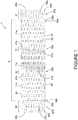
- Figure 1 is a top view of an embodiment of a panel (1) for use in the textile.
- Panel (1) can be manufactured to any width and length. However, for some applications, the distance (or panel length) between outer edges (26a) and (26b) can be between 0.5m and 1.0m while the distance (or panel width) along the outer edge (e.g. 26a, 26b) can be as large as required. For example, the panel width can be approximately equal to the required textile width.
- Panel (1) includes a body region (5) located in between first and second fold regions (61, 62).
- Each fold region (61, 62) includes an outer edge (26a, 26b), an inner edge (28a, 28b), a column of hem slots (45a, 45b) and hem loop strips (25a, 25b); and a hem fold line (27a, 27b) midway through the column of hem slots (45a, 45b) and hem loop strips (25a, 25b).
- hem slots (45a, 45b) and hem loop strips (25a, 25b) will be used to hem the fold regions (61, 62) of the panel (1).
- the body region (5) extends between first and second inner edges (28a, 28b).
- Body region (5) also includes first and second seam columns of seam slots (41a, 41b) and seam loop strips (21a, 21b), with a seam fold line (35a, 35b) midway between each seam column.
- First and second seam regions (31, 32) are defined by the respective seam slots (41a, 41b), seam loop strips (21a, 21b) and seam fold lines (35a, 35b).
- seam slots (41a, 41b) and seam loop strips (21a, 21b) will be used to define a seam between adjacent folded panels.
- Body region (5) can also be defined in terms of first and second end body regions (11a, 11b) and a central body region (11c).
- hatching has been used to depict the inner surface of central body region (11c); this hatching does not imply that the composition of (11c) differs from that of end body regions (11a, 11b).
- Each end body region (11a, 11b) extends between its respective inner edge (28a, 28b) and seam fold line (35a, 35b), while the central body region (11c) extends between the first and second seam fold lines (35a) and (35b).
- End body regions (11a, 11b) are generally equal in length (i.e.
- each end body region (11a, 11b) can approximately equal the length (i.e. the distance between seam fold lines (35a, 35b)) of the central body region (11c).
- Body region (5) includes a series of columns of protrusions (57), with a land channel (56) in between each column. Protrusions (57) within a column are separated by a land area (53). As shown in Figure 2A . Protrusions (57) protrude outward from the inner surface of the panel (1).
- the protrusions (57) can be embossed throughout leaving depressions on the outer surface of panel (1).
- Protrusions (58a, 58b) are proximate the inner edge (28a, 28b) of each fold region (61, 62).
- the columns of protrusions (57) across the length of panel (1) are staggered (in a 1-2-1-2... pattern), while in each fold region (61, 62), each hem slot (45a, 45b) is directly across a protrusion (58a, 58b) proximate the inner edge (28a, 28b).
- protrusions (57) are arranged in regular columns oriented parallel to the seam fold lines (35a, 35b), other spatial arrangements of the protrusions may be possible such as offset (in relation to one another).
- protrusions (57) may all have the same size and shape, although other embossing patterns and protrusion shapes, such as those disclosed in WO 2013/181748 , WO 2013/188964 , WO 2014/053055 or WO 2014153644 (all of which are incorporated by reference) may be used.
- Figure 2A illustrates a side view of the panel (1) of Figure 1 showing the first folding step of the panel (1).
- Figure 2B is a perspective view of Figure 2A .
- the protrusions (57) can be further slit on their lateral sides in a precision slitting process to form apertures (55), as shown in Figure 2A .
- Each protrusion (57) includes a surface (51) supported by side surfaces (52), with an aperture (55) on one or both lateral sides.
- the inner surface in body region (5) forms a continuous outwardly profiled surface with depressions on the outer surface thereof.
- Apertures (55) allow for movement of fluid and/or air from one panel surface through to the other surface in the folded panel, while also providing a passageway (across the width of the folded panel) that can receive a filamentary element to allow for mechanical securement of the central body region with (11c) with two opposite end body regions (11a, 11b). This feature is discussed further below.
- panel (1) is folded along each fold line (27a, 27b), such that each fold region (61, 62) is folded into a U-shape.
- Each outer edge (26a, 26b) (shown in Figure 1 ) is folded towards the inner surface of the panel (1), and is approximately above the respective inner edge (28a, 28b) (see Fig. 1 ).
- This folding process forms hem loops (25a, 25b) alternating with hem loop-receiving openings (45a, 45b).
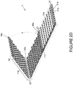
- FIGs 2C and 2D illustrate a subsequent folding of panel (1) after the initial folding step shown in Figures 2A and 2B .
- Panel (1) is folded along seam fold lines (35a, 35b), such that each end body region (11a, 11b) is folded toward central body region (11c).
- This folding step results in the formation of seam loops (21a, 21b) and seam loop-receiving openings (41a, 41b) at each end of panel (1) (note that only (21a) and (41a) are shown in Figure 2D ).
- end body region (11b) is being folded along the arc marked 'X', while end body region (11a) has been completely folded so that it is in contact with central body region (11c).
- Fold region (61) is nestled approximately at a midway point of central body region (11c), with hem loops (45a) receiving protrusions (57) from the central body region (11c).
- fold region (62) will be nestled approximately at a midway point of central body region (11c), with hem loops (45b) receiving protrusions (57) from the central body region (11c).
- Fold regions (61, 62) can be secured to the central body region (11c) in a manner described below.
- columns of protrusions from end body regions (11a, 11b) generally overlap in a staggered formation with columns of protrusions from the central body region (11c), such that the surface (51) of a protrusion (57) contacts an opposite land area (53). This is discussed in greater detail below.
- FIG 3A illustrates the folded panel (10) once both end body regions (11a, 11b) are brought into contact with the central body region (11c), following the folding process illustrated in Figures 2A to 2D .
- Hem region (65) is defined as the overlap of fold regions (61, 62).
- end body regions (11a, 11b) form a first layer of folded panel (10)
- central body region (11c) forms a second layer of folded panel (10).
- the central body region (11c) may be oriented towards the product-conveying side of the industrial textile so that hem region (65) is oriented towards the machine.
- FIG. 3B illustrates in greater detail the hem region (65).
- Hem loop-receiving openings (45a, 45b) interconnect as follows. Hem loops (25a) of fold region (61) are inserted into hem loop-receiving openings (45b) of fold region (62), while hem loops (25b) of fold region (62) are inserted into hem loop-receiving openings (45a) of fold region (61). Furthermore, hem loop-receiving openings (45a, 45b) are dimensioned so as to receive protrusions (57) from central body region (11c).
- outer edges (26a, 26b) are aligned with protrusions (58a, 58b) so that surfaces of edge regions (85a, 85b) are located on the lower planar surface of land channel (56), and secured thereto (as discussed below).
- FIG 3C shows an enlargement of the seam region (31) at which adjacent panels may be joined.
- Seam region (31) includes a plurality of regularly spaced seam loops (21a) between which are located seam loop-receiving openings (41a).
- Seam loops (21a) and seam loop-receiving openings (41a) are formed by folding panel (1) at first seam fold line (35a) (shown in Figures 2C and 2D ), in the manner described above.
- seam channel (80) is formed via the seam loops (21a).
- FIG 4 is a side view of the folded panel (10) shown in Figures 3A to 3C .
- Hem region (65) includes interconnected fold regions (61, 62), such that hem channel (95) is formed by the overlap of hem loops (25a, 25b).
- a hem connecting member shown as (97) in Figures 6A and 6B ) may be inserted into hem channel (95) to secure the fold regions (61, 62) together.
- Seam regions (31, 32) include seam loops (21a, 21b).
- a seam channel (80) is formed within each set of seam loops (21a, 21b).
- edge regions (85a, 85b) can be secured to the inner surface of central body region (11c) at land channel (56), thereby configuring the folded panel (10) into a complete self-contained unit.
- the free ends (i.e. fold regions 61, 62) of the original panel (1) are contained within the first and second layers. That is, edge regions (85a, 85b) are shielded between the inner surfaces of end body regions (11a, 11b) and the inner surface of central body region (11c).
- Resistance to compression by the folded panel (10) can be enhanced by the optional insertion of a filamentary member (90), or similar material, through one or more aligned apertures (55) in the interior of folded panel (10).
- FIG. 5 is a top view of the folded panel (10) shown in Figure 4 , illustrating the insertion of hem loops (25a, 25b) into corresponding hem loop-receiving openings (45a, 45b). Furthermore, protrusions (57) from central body region (11c) are visible, as they are received by hem loop-receiving openings (45a, 45b).
- a hem channel (95) is formed allowing for receipt of a pintle or monofilament to further secure hem region (65).
- the interconnected hem loops (25a, 25b) can be secured in place using methods described below.
- Seam loops (21a, 21b) and seam loop-receiving openings (41a, 41b) are located at opposing ends of the folded panel (10), for interconnection with an adjacent folded panel, as described below.
- An industrial textile is constructed by interconnection of a series of adjacent folded panels by intermeshing the seam loops and seam loop receiving openings at the seam regions located at opposing ends of the folded panels. This is further illustrated in Figures 6A , 6B and 7 .
- the number of folded panels used to build the textile can vary according to the required textile length.
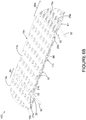
- Figure 6A provides a perspective view of a portion of a first embodiment of an industrial textile (100) constructed from a series of interconnecting folded panels (10a, 10b), in which the two interconnected panels (10a, 10b) are constructed as shown in Figures 3A to 3C .
- the direction of motion of the textile (100) is indicated by the arrow labeled MD, while the cross-machine direction (CD) is indicated as perpendicular to the MD.
- folded panels (10a, 10b) are interconnected at composite seam region (20), which includes seam loops from seam region (32) of folded panel (10a) interconnected with seam loops from seam region (33) of folded panel (10b) by a seam connecting member (82) (such as a pin, a pintle, a monofilament, or similar member known in the art).
- a seam connecting member (82) such as a pin, a pintle, a monofilament, or similar member known in the art.
- the hem regions (65a, 65b) of panels (10a, 10b) can be further secured by insertion of a hem connecting member (97) such as a monofilament or pin (or similar member known in the art) in the hem channel.
- a hem connecting member (97) such as a monofilament or pin (or similar member known in the art) in the hem channel.
- one or more hem connecting members (97) may be used; i.e. it is not necessary to secure all of the hem regions in the textile (100) with a connecting member (97). If a hem connecting member (97) is not used to secure a hem region (e.g. 65a, 65b), then such hem regions (65a, 65b) can be secured in a manner described in relation to Figure 8 .
- An enlarged view of composite seam region (20) and hem region (65a) of panel (10a) is provided in Figure 6B .
- the end body regions (11a, 11b, 12a, 12b) provide a surface that may face towards the machine on which the industrial textile is used; this surface is referred to as the "machine-side” (MS) surface.
- Central body regions (11c, 12c) may provide the product conveying side of the industrial textile; this surface is referred to as the "product-side” (PS) surface.
- MS machine-side
- PS product-side
- the distinction between the MS and PS is due to the location of the hem regions (65a, 65b). That is, the hem regions (65a, 65b) are on the MS.
- end body regions (11a, 11b) of folded panel (10a) are interconnected at hem region (65a) by means of a hem connecting member (97), such as a monofilament, which is inserted through the interdigitated hem loops (25a, 25b) of fold regions (61, 62).
- Protrusions (57) on the end and central body regions (11a, 11b, 11c) are oriented towards the interior of folded panel (10a), while the depressions are visible on the outer surfaces of each folded panel (10a, 10b).
- At least one lateral side of the protrusions (57) includes an aperture opening (55).
- folded panel (10a) protrusions (57) of end body regions (11a, 11b) are aligned with those of central body region (11c) such that the apertures (55) allow for movement of fluids, air and materials through the industrial textile (100).
- Folded panel (10b) is interconnected to folded panel (10a) by intermeshing of seam loops (21a, 21b) to provide a seam channel (not shown) through which seam connecting member (82) can be inserted.
- Multiple folded panels such as (10a) and (10b) may be interconnected in series in this manner so as to build up the length of the industrial textile (100) as required.
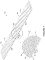
- Figure 7 is a perspective view showing the second surface of the two interconnected panels shown in Fig. 6A , and magnification of the interconnection region between the two folded panels, in which surface roughness has been applied to the outer surface of the central body regions (11c, 12c) of each folded panel (10a, 10b). That is, Figure 7 is a perspective view of what may be used as the product side (PS) surface of the industrial textile (100) as defined above.
- PS product side
- the hem regions (65a, 65b) are on the opposite machine side (MS) of the textile (100).
- protrusions (57) on the inner surface of the PS layer are aligned with, and engage with, corresponding protrusions (57) on the inner surface of the MS layer.
- a protrusion surface is secured to a corresponding planar land area of an opposing layer, as described in relation to Figure 8 .
- Seam loops from seam region (32) of panel (10a) are intermeshed with corresponding loop receiving openings in seam region (33) of panel (10b) forming seam channel (80) allowing for the interconnection of the two panels at composite seam region (20) by inserting a pin or pintle (such as (82) as described in Figure 6B ).
- the outer surface of the folded panels can have roughness thereon.
- An example of surface roughness is shown in the magnification of Figure 7 , where a portion of the outer surface of folded panels (10a, 10b) includes striations (48), as an example. Surface roughness is applied to reduce adherence of external contaminants. Other examples of surface roughness are described in US Patent No. 6,773,786 .
- Figure 8 is a side view of the hem region (65) of the folded panel (10) shown in Figure 4 , illustrating various internal construction features.
- Figure 8 is similar to Figure 4 and illustrates several possible securing methods in each of circled regions 8A through 8F that may be employed to secure the end and central body regions (11a, 11b, and 11c) forming the PS and MS layers of folded panel (10). These will each be discussed in turn.
- Figure 8A is an enlargement of circled area 8A in Figure 8 and illustrates the use of filamentary member (90), such as a monofilament or other yarn, inserted through aligned lateral apertures (55) of engaged protrusions (57) across the width of the interconnected folded panel (10).
- the filamentary member (90) mechanically interlocks the upper and lower panel layers through their aligned apertures (55) so as to prevent separation.
- This interconnection process may be repeated across the width and length of the textile at selected locations in order to reinforce the interconnection of the panel layers in the textile, and may be used either in place of, or in addition to, protrusion bonding locations such as (71a, 71b) shown in Figure 8B .
- Figure 8B is an enlargement of circled area 8B in Figure 8 illustrating one possible method of interconnecting the end fold regions (11a, 11b) with central body region (11c).
- Surface (51b) of protrusion (57b) located in end body region (11b) may be secured to the opposing planar area (53c) in central body region (11c), by means of a weld (71b) between these two surfaces.
- Welding can include, for example, through transmission laser welding (TTLW).
- TTLW transmission laser welding
- surface (51c) of protrusion (57c) located in central body region (11c) may be secured to opposing planar area (53b) by a weld at (71c).
- TTLW can be used as a securing method when the panel is formed from a thermoplastic, such as polyester.
- Other bonding methods including other welding methods (e.g.
- ultrasonic, vibrational, induction adhesives (such as chemical solvent adhesives, hot melt adhesives, epoxies and the like) or mechanical fasteners (e.g. inserts, snap-fits, swaging, staking) can be employed when the panel comprises a thermoset or a metal, since laser welding is not feasible in such cases.
- adhesives such as chemical solvent adhesives, hot melt adhesives, epoxies and the like
- mechanical fasteners e.g. inserts, snap-fits, swaging, staking
- Figure 8C illustrates the use of a spacer member (75) secured within fold region.
- Spacer member (75) can be placed in contact with edge region (85b) and an inner surface of the fold region, at contact points (e.g. 73b, 73c).
- One or more spacer members (75) can be used at selected edge regions and may be either continuous or discontinuous across the folded panel (10) width.
- Spacer member (75) can be formed from any suitable material, such as a material similar to, or substantially the same as that used to prepare the panels.
- the spacer member (75) may further comprise a laser weld enabling material, such as a polymeric monofilament, film or the like, which includes a suitable radiant energy absorber.
- the spacer member (75) should have a height that does not cause significant discontinuity in the otherwise planar surface of the folded panels.
- the width of the spacer member (75) should be such as to be accommodated by a land channel.
- the spacer member (75) can be bonded, for example, by laser welding at each of contact points (73b, 73c). Use of a spacer member (75) is optimal in the assembly of an industrial textile.
- Figure 8D illustrates a cross-sectional view of a hem region (65) including hem channel (95) with a hem connecting member (97) inserted therein.
- a hem connecting member (97) include a pin, a pintle, a monofilament or any other suitable material.
- a foam (67) such as an open cell porous foam or a closed cell foam can be inserted into the open spaces between end and central body regions (11a) and (11c). This can also occur in open spaces between end and central body regions (11b) and (11c).
- Foam (67) may provide additional compression resistance and enhance the strength of attachment between the folded panel (10) layers.
- porous nature of the open cell foam allows for the passage of fluids and/or air through the textile assembly; however, both an open or closed cell foam will further ensure both a strong bond between the opposing panel layers, and resistance to compressive forces that may be applied to the textile when in use.
- Figure 8E illustrates a portion of one edge region (85a) of panel (10) following interconnection at hem region (65). Edge region (85a) is secured at (74a) to land channel (56c) in central body region (11c). Securement may be formed by TTLW or other suitable means.
- Figure 8E also shows insertion of foam (67) (as described above) into the interior region between body regions (11a, 11c) proximate hem region (65). The foam (67) may be optionally injected into either the regions above land channel (56c), the apertures (55), into the exposed cavities of the folded panel (10), or any combination thereof prior to construction of the textile.
- Figure 8F illustrates the optional insertion of a foam (67) (as described above) injected into either the volume between land channels (not shown), apertures (55) remote from the hem region (shown in Figure 8E ), or into the exposed lower surfaces of central body region (11c), or any combination thereof, prior to construction of the textile.
- the interconnection of the panel layers may be optionally reinforced by securing top surfaces (51) of protrusions (57) to opposing planar area (53) as shown at (71a, 71c) in the manner previously described.
- FIG 9 illustrates an alternate arrangement of securing edge regions (85a, 85b) of the folded panel (10) arranged in the manner previously discussed.
- edge regions (85a, 85b) are secured at regions (74a) and (74b) to the inner surfaces of fold regions (61, 62), respectively. That is, each end fold region (61, 62) is no longer folded in a "U" shape (as in Figures 2 to 8 ), but rather, is arranged as a "rope hem” configuration.
- a portion (83a, 83b) of each end fold region (61, 62) is brought around hem channel (95) and is directed towards the inner surface of the fold regions (61, 62).
- Each edge region (85a, 85b) is in contact with the inner surface of the fold region (61, 62) where it is secured at (74a, 74b) in a manner described above.
- the embodiment presented in Figure 9 provides an alternate arrangement of the hem region in the construction and assembly of the textile. When a rope hem is used, securement of the end body regions (11a, 11b) with central body region (11c) can be achieved via one or more of the methods illustrated in Figs. 8A , 8B , 8D , and 8F .
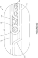
- Figure 10 is a perspective view of an embodiment of a double layer non-woven industrial textile (180) constructed from a plurality of folded panels such as (10a) and (10b) which are constructed and arranged as described above.
- a non-woven seaming element (150) can be used to join opposite ends of the assembled textile (180) to form a continuous belt that can be released by removal of seaming element (150).
- Folded panels are secured in series to form the textile (180) by interconnecting each of the multiple panels at their respective seam regions (for example at (31, 32, 33, 34) in Figure 6A ), as described above.
- Folded panels e.g., 10a, 10b
- hem regions e.g. (65a, 65b)
- the textile (180) is also defined by lateral edges (105, 106), which are common to all of the interconnected folded panels (e.g. (10a, 10b)).
- the folded panels (e.g., (10a, 10b)) can be secured from within by any of the methods described in relation to Figs. 8-8F and 9 . Furthermore, the upper surfaces of the central body regions of the folded panels (e.g. (10a, 10b)) can be provided with surface roughness, as shown, for example, in Figure 7 .
- folded panels such as (10a, 10b) are interconnected in the manner previously described as required to provide a given length of finished textile (180).
- Each folded panel is oriented so that its hem (e.g. 65a, 65b) and composite seam regions (e.g. 20) are transverse to the intended run direction, or MD, of the textile (180).
- the textile (180) is then cut in the CD within a central body region of the folded panels (e.g.
- the finished industrial textile (180) is thus a wholly non-woven double layer assembly that includes a seaming element (150) that allows for installation and removal of the textile (180).
- Figure 11 is a plan view of a surface of a second embodiment of a non-woven double-layer industrial textile (200) which may be used as the product side (PS). In this view, the hem regions are hidden below the PS surface. All of the folded panels (e.g. 10a, 10b, 1 10a, 110b) are constructed as described above, and interconnected at composite seam regions (20) across the MD as described above. In this embodiment of the textile (200), folded panels (e.g. 10a, 10b) are secured in the CD at their first (121a, 121b) and second (122a, 122b) lateral edges to folded panels (110a, 110b).
- folded panels e.g. 10a, 10b
- Securement across the lateral edges can be achieved, for example, by insertion of filamentary member (90) through aligned apertures (55) in the manner shown in Figure 8A .
- folded panels (10a, 10b) are referred to as “interior panels” while folded panels (110a, 110b) are referred to as “exterior panels”.
- adjacent interior panels (10a, 10b) are offset, so that their lateral edges (121a, 121b) and (122a, 122b) are discontinuous. This results in composite seam regions (20) that include a combination of interconnections between folded panels (10a) with (10b); (10b) with 110 (a), (110a) with (110b), and so on.
- Each exterior panel (110a, 110b) is structured and arranged to be identical with interior panels (10a, 10b). However, each of the exterior panels (110a, 110b) is made from a material different than that used in the composition of interior panels (10a, 10b).
- folded panels (10a, 10b) may be formed from a film comprised of polyethylene terephthalate (PET).
- PET polyethylene terephthalate
- the lateral edges of the textile (200) may be exposed to excess wear, heat and humidity, in which case, the PET may degrade (hydrolyze) more quickly than would be desirable.
- exterior panels (110a, 110b) that are made from heat- and hydrolysis-resistant materials, in the lateral regions of the textile (200) as shown in Figure 11 , it would be possible to prolong the service life of these exterior edges that are exposed to direct heat in the dryer section.
- heat-resistant and hydrolysis-resistant materials include polyphenylene sulfide (PPS) or polyaryletherketones such as PEEK.
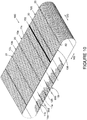
- Figure 12 is a partial perspective view of the non-woven industrial textile shown in Figure 11 . Depressions visible in the outer surfaces of folded panels (10a, 10b) are formed by protrusions in the folded panels, as described previously.
- exterior panels (110a, 110b) may be attached in the following manner. Interior panels (10a, 10b) are interconnected in textile (200) such that lateral edges (121a, 121b) and (122a, 122b) are offset so that their lateral edges are staggered as shown in Figure 11 . Adjacent internal panels (10a, 10b) are secured to each other at composite seam regions (20), as previously described. A lateral edge of external panel (110a) is then aligned with lateral edge (121a) of one of the internal panels (10a). Since all of the folded panels are identical in structure, exterior panel (110a) is then interconnected to adjacent interior panels (10b) at seam regions (20) on either side of (110a).
- a seam connecting member (82) can be inserted in the seam channel (80) (e.g. as in Figure 7 ) formed in the composite seam regions (20) on either side of folded panels (10a) and (110a). This process is repeated for each exterior panel (110a, 110b) attached to the lateral edges (121a, 121b) of interior panels (10a, 10b) as well as at their opposite lateral edges (122a, 122b), if desired.
- a hem connecting member (97) can be inserted through the hem channel (95) at hem regions (e.g. 65a, 65b, 165a, 165b) of exterior panels (110a, 110b) and corresponding interior panels (10a, 10b) so as to further reinforce the folded panel interconnection in both the MD and CD.
- connection between exterior panels (110a, 110b) and corresponding interior panels (10a, 10b) in the CD can be further reinforced by inserting a filamentary element (90) through the aligned apertures of the folded panels in the manner described in relation to Figure 8A , so as to span at least a portion of the CD panel width.
- the outer lateral edges (115a, 115b) of exterior panels (110a, 110b) are then trimmed to remove any nonlinear variations.
- the edges (115a, 115b) can be sealed by heat, chemical or other suitable means to prevent migration of the filamentary member (90) from the aligned apertures.
- Panels used in the construction of a double-layer non-woven industrial textile can include a thermoplastic polymer material, such as (but not exclusively) polyesters, polyolefins and polyamides.
- the panel can include a thermoset polymer, such as (but not exclusively) polyimides.
- a formable metal may also be used in the construction of a panel.
- the panel is comprised of thermoplastics, laser welding can be used to secure panel surfaces and components to each other. Other bonding methods, such as chemical adhesives and mechanical attachments, can also be used.
- the panels can be formed from a film that comprises a medium to high intrinsic viscosity (IV) polyester selected from the group consisting of polyethylene terephthalate (PET), polybutylene terephthalate (PBT), polyethylene naphthalate (PEN), and poly(cyclohexylene dimethylene terephthalate) acid (PCTA).
- IV intrinsic viscosity
- PET polyethylene terephthalate
- PBT polybutylene terephthalate
- PEN polyethylene naphthalate
- PCTA poly(cyclohexylene dimethylene terephthalate) acid
- the panels can be made of polyphenylene sulphide (PPS), polyaryl ether ketones (PAEK) such as polyether ether ketones (PEEK), poly(cyclohexylene dimethylene terephthalate) acid (PCTA) or a hydrolysis-stabilized thermoplastic material.
- PPS polyphenylene sulphide
- PAEK polyaryl ether ketones
- PEEK polyether ether ketones
- PCTA poly(cyclohexylene dimethylene terephthalate) acid
- hydrolysis-stabilized thermoplastic material a hydrolysis-stabilized thermoplastic material.
- a film of polyester, in particular polyethylene terephthalate (PET), and having an IV that is between about 0.5 and 1.0 can be used.
- the film may be coextruded in two or more layers, or otherwise may consist of multiple layers.
- At least one layer of the PET film may also be biaxially oriented and hydrolytically stabilized to prevent premature depolymerization due to hydrolytic degradation when the film structure is intended for use in hot and moist environments.
- carbodiimides can be used. Examples of such films are disclosed in WO 2013/177670 (incorporated herein by reference) in which the film is oriented in both the longitudinal and transverse directions to maximize its elastic modulus and other physical properties, such as tensile strength and free shrinkage.
- the film, or at least one layer of a multilayer film comprises a hydrolytic stabilizer comprising a carbodiimide.
- the carbodiimide comprises between 0.5% parts by weight (w/w) and 5% w/w of the material of that layer.
- the carbodiimide can be selected from a monomeric form and a polymeric form. In particular the carbodiimide can be polymeric.
- the polymer film material used in the panel structures can also include a laser-weld enabling material; at least one film layer can comprise a radiant energy absorbent material such as carbon black.
- a polymeric film material is disclosed in WO 2013/071419 .
- the film material can comprise at least two coextruded miscible layers in which at least one outer layer includes a radiant energy absorbent material and is about from 5% to 20% of the overall film thickness or caliper, which may be from about 100 ⁇ m up to 500 ⁇ m.
- the overall film thickness can also be in the range of about 250 ⁇ m to 350 ⁇ m.
- a first layer can include a radiant energy absorbent material and can comprise from 5% to 15% of the overall film thickness, while the second layer can comprise from 85% to 95% of the overall film thickness.
- the first layer can comprises about 10% of the film thickness and the second layer can comprise about 90% of the film thickness.
- each outer layer can comprise from 5% to 20% of the overall film thickness and an inner layer can comprise from 60% to 90% of the total film thickness.
- each outer layer can comprise from 10% to 15% of the film thickness and the inner layer can comprise from 70% to 80% of the film thickness.
- At least one of the two outer layers can comprise a radiant energy absorbent material.
- the absorbent can be carbon black which is incorporated so as to comprise from about 0.1% w/w to about 1% w/w of the polymer material in the film layer.
- radiant energy absorbing materials such as clear or dyeable products e.g. Clearweld® (available from Gentex Corporation of Carbondale, PA) or Lumogen® (available from Basf Corporation) may also be used.
- the amounts of the additive used will depend on the additive selected, but where the additive is carbon black, it can be present in amounts ranging from about 0.1% w/w to about 1.0% w/w based on the total weight of the at least one outer film layer.
- the amount of laser energy absorbent material additive incorporated into the film layer depends on the final thickness of the layer, taking into account the wavelength of the laser intended to be used in the welding process.
- At least one layer of the multilayer film can further comprise an additive, such as at least one of titanium dioxide, or at least one dye.
- the panel may be constructed of a thermoset polymer material such as a commercially available linear or aromatic heterocyclic polyimides which are sold in the marketplace under the tradenames ApicalTM, KaptonTM, UPILEXTM, VTEC PITM, Norton THTM and KaptrexTM; others may be suitable.
- Thermosets are not amenable to laser welding and can be bonded using one of an epoxy, a solvent or chemical adhesive such as a hot melt adhesive.
- a formable metal material may also be employed and, in particular, a formable metal material selected from at least one of aluminum alloy, brass, cold rolled steel, copper, galvanized steel, high strength low alloy steel, hot rolled steel, steel alloys, stainless steel and zinc.
- a formable metal material refers to a metal that that can undergo strain beyond the elastic limit of the material without causing excessive strain localization or fracture. Panels formed from these metals are amenable to both laser and resistance welding and can be bonded by these or similar means.
Claims (15)
- Paneel (1) zur Verwendung bei der Konstruktion eines technischen Vliesstoffs (180), wobei das Paneel (1) umfasst:a) eine Innenfläche und eine Außenfläche;b) zwei gegenüberliegende Seitenkanten (105, 106) und zwei gegenüberliegende Außenkanten (26a, 26b);c) erste und zweite Faltungsbereiche (61, 62) an jedem Ende des Paneels (1), wobei jeder Faltungsbereich umfasst:i) eine Außenkante (26a, 26b) des Paneels (1);ii) einen Randbereich (85a, 85b);iii) eine Spalte von Saumschlaufenstreifen (25a, 25b) und Saumschlitzen (45a, 45b), wobei die Spalte parallel zur Außenkante (26a, 26b) ausgerichtet und angrenzend an den Randbereich (85a, 85b) gesetzt ist; undiv) eine Saumfaltungslinie (27a, 27b), die im Wesentlichen in der Mitte der Spalte von Saumschlaufenstreifen (25a, 25b) und Saumschlitzen (45a, 45b) verläuft, wobei die Saumfaltungslinie (27a, 27b) parallel zu der Außenkante (26a, 26b) ausgerichtet ist;d) einen Körperbereich (5) zwischen dem ersten und zweiten Faltungsbereich (61, 62), wobei der Körperbereich (5) umfasst:wobei das Paneel (1) ein gefaltetes Paneel (1) bildet, wenn das Paneel (1):i) mehrere Vorsprünge (57) und Landflächen (53) auf der Innenfläche des Paneels (1), mit einer Landfläche (53) zwischen jedem Vorsprung (57);ii) erste und zweite Nahtbereiche (31, 32), wobei jeder Nahtbereich (31, 32) umfasst: eine Spalte von Nahtschlitzen (41a, 41b) und Nahtschleifenstreifen (21a, 21b), wobei die Spalte parallel zur Außenkante (26a, 26b) ausgerichtet ist; und eine Nahtfaltungslinie (35a, 35b), die im Wesentlichen in der Mitte der Spalte von Nahtschleifenstreifen (21a, 21b) und Nahtschlitze (41a, 41b) verläuft, parallel zur Außenkante (26a, 26b) ausgerichtet;iii) erste und zweite Endkörperbereiche (11a, 11b), wobei der erste Endkörperbereich (11a) zwischen dem ersten Faltungsbereich (61) und der ersten Nahtfaltungslinie (35a) liegt;
die zweite Endkörperregion (11b) zwischen dem zweiten Faltungsbereich (62) und der zweiten Nahtfaltungslinie (35b) liegt; undiv) einen mittleren Körperbereich (11c) zwischen der ersten und zweiten Nahtfaltungslinie (35a, 35b);zuerst entlang jeder Saumfaltungslinie (27a, 27b) gefaltet wird, so dass jede Außenkante (26a, 26b) zur Innenfläche des Paneels (1) ausgerichtet ist, jeder Saumschlaufenstreifen (25a, 25b) eine Saumschlaufe (25a, 25b) bildet und jeder Saumschlitz (45a, 45b) eine Saumschlaufenaufnahmeöffnung (45a, 45b) für die Aufnahme einer Saumschlaufe (25a, 25b) des gegenüberliegenden Faltungsbereichs bildet;dann anschließend entlang jeder Nahtfaltungslinie (35a, 35b) gefaltet wird, so dass die Innenfläche des Paneels (1) an jedem Endkörperbereich (11a, 11b) gegenüber der Innenfläche des Paneels (1) an dem mittleren Körperbereich (11c) ausgerichtet ist; der erste und zweite Faltungsbereich (61, 62) an einem Saumbereich (65) miteinander verbunden und zwischen dem mittleren Körperbereich (11c) und den jeweiligen Endkörperbereichen (11a, 11b) eingebettet sind; jeder Nahtschlaufenstreifen (21a, 21b) eine Nahtschleife (21a, 21b) bildet; jeder Nahtschlitz (41a, 41b) eine Nahtschlaufenaufnahmeöffnung (41a, 41b) zur Aufnahme einer Nahtschlaufe (21a, 21b) eines benachbarten gefalteten Paneels (10) bildet; die kombinierten Endkörperbereiche (11a, 11b) eine erste Schicht des gefalteten Paneels bilden, der mittlere Körperbereich (11c) eine zweite Schicht des gefalteten Paneels (10) bildet; und die erste Schicht an der zweiten Schicht durch Sichern von Vorsprüngen (57) in der ersten Schicht an gegenüberliegenden Landflächen (53) in der zweiten Schicht und/oder Sichern von Vorsprüngen (57) in der zweiten Schicht an gegenüberliegenden Landflächen (53) in der ersten Schicht gesichert ist. - Paneel (1) nach Anspruch 1, wobei die mehreren Vorsprünge (57) in einer Reihe von Spalten parallel zu jeder Spalte von Nahtschlaufenstreifen (21a, 21b) und Nahtschlitzen (41a, 41b) angeordnet sind.
- Paneel (1) nach einem der Ansprüche 1 bis 2, wobei jeder Vorsprung (57) mindestens eine seitliche Öffnung (55) aufweist.
- Paneel (1) nach Anspruch 3, wobei die mindestens eine seitliche Öffnung (55) einen Strömungspfad für Fluid und/oder Luft vorsieht, um zwischen der Außenfläche und der Innenfläche des Paneels (1) durchzutreten.
- Paneel nach einem der Ansprüche 1 bis 4, wobei bei dem gefalteten Paneel (10) jeder Faltungsbereich (61, 62) zu einer U-Form gefaltet ist und die Faltungsbereiche (61, 62) durch mindestens einen der folgenden miteinander verbunden sind:a) ein Saumverbindungselement (97), das in einen Saumkanal (95) gesetzt ist, der durch die miteinander verbundenen Faltungsbereiche (61, 62) gebildet ist; undb) jeder Randbereich (85a, 85b) an der Innenfläche des gegenüberliegenden Endkörperbereichs (11a, 11b) befestigt ist.
- Paneel (1) nach einem der Ansprüche 1 bis 5, welches ein thermoplastisches Material, ein duroplastisches Material oder ein formbares Metall umfasst.
- Zweilagiger technischer Vliesstoff (180), der aus mehreren gefalteten Paneelen (10a, 10b) hergestellt ist, die benachbart in Reihe befestigt sind, wobei:a) jedes gefaltete Paneel (10a, 10b) nach Anspruch 1 ausgebildet ist;b) benachbarte gefaltete Paneele (10a, 10b) an einem Verbundnahtbereich (20) miteinander verbunden sind, wobei der Verbundnahtbereich (20) durch Einfügen der Nahtschlaufen (21a) eines ersten gefalteten Paneels (10a) in die Nahtschlaufenaufnahmeöffnungen (41b) eines zweiten gefalteten Paneels (10b) und der Nahtschlaufen (21b) des zweiten gefalteten Paneels (10b) in die Nahtschlaufenaufnahmeöffnungen (41a) des ersten gefalteten Paneels (10a) gebildet ist, wodurch ein Nahtkanal (80) an dem Verbundnahtbereich (20) gebildet wird; undc) die benachbarten gefalteten Paneele (10, 10b) durch Einsetzen eines Nahtverbindungselements (82) in den Nahtkanal (80) zwischen den benachbarten gefalteten Paneelen (10a, 10b) aneinander befestigt sind.
- Zweilagiger technischer Vliesstoff (180) nach Anspruch 7, wobei in jedem gefalteten Paneel (10a, 10b) die mehreren Vorsprünge (57) in einer Reihe von Spalten parallel zu jeder Spalte von Nahtschlaufenstreifen (21a, 21b) und Nahtschlitzen (41a, 41b) angeordnet sind.
- Zweilagiger technischer Vliesstoff (180) nach Anspruch 7 oder 8, wobei jeder Vorsprung (57) mindestens eine seitliche Öffnung (55) aufweist.
- Zweilagiger technischer Vliesstoff (180) nach Anspruch 9, wobei der mittlere Körperbereich (11c) und die Endkörperbereiche (11a, 11b) mindestens eines gefalteten Paneels (10a, 10b) ferner durch mindestens ein Filamentelement (90) miteinander verbunden sind, das durch ausgerichtete Öffnungen (55) einer Spalte von Vorsprüngen (57) in der ersten Schicht verläuft, die mit einer Spalte von Vorsprüngen (57) in der zweiten Schicht versetzt sind.
- Zweilagiger technischer Vliesstoff (180) nach einem der Ansprüche 7 bis 10, wobei bei jedem gefalteten Paneel (10a, 10b) jeder Faltungsbereich (61, 62) zu einer U-Form gefaltet ist und die Faltungsbereiche (61, 62) durch mindestens eines der folgenden miteinander verbunden sind:a) ein Saumverbindungselement (97), das in einem Saumkanal (95) gesetzt ist, der durch die miteinander verbundenen Faltungsbereiche (61, 62) gebildet ist; undb) jeder Randbereich (85a, 85b) ist an der Innenfläche des gegenüberliegenden Endkörperbereichs (11a, 11b) befestigt.
- Zweilagiger technischer Vliesstoff (180) nach einem der Ansprüche 7 bis 11, wobei jedes gefaltete Paneel (10a, 10b) ein thermoplastisches Material, ein duroplastisches Material oder ein formbares Metall umfasst.
- Paneel (1) nach Anspruch 3, weiterhin umfassend:a) mindestens eine Schicht aus Polymerfolie aus orientiertem PET, die ein strahlungsenergieabsorbierendes Material umfasst.
- Paneel (1) nach Anspruch 13, wobei die Polymerfolie biaxial ausgerichtet ist.
- Paneel (1) nach einem der Ansprüche 13 bis 14, wobei das Paneel mindestens zwei coextrudierte Schichten aus Polymerfolie umfasst und eine der mindestens zwei coextrudierten Schichten ein strahlungsenergieabsorbierendes Material umfasst.
Applications Claiming Priority (2)
| Application Number | Priority Date | Filing Date | Title |
|---|---|---|---|
| CA2835951 | 2013-12-06 | ||
| PCT/CA2014/000864 WO2015081417A1 (en) | 2013-12-06 | 2014-12-05 | Non-woven double-layer industrial textile assembled from sleeve configuration panels, and panels therefor |
Publications (3)
| Publication Number | Publication Date |
|---|---|
| EP3077593A1 EP3077593A1 (de) | 2016-10-12 |
| EP3077593A4 EP3077593A4 (de) | 2017-11-08 |
| EP3077593B1 true EP3077593B1 (de) | 2018-11-14 |
Family
ID=53272675
Family Applications (2)
| Application Number | Title | Priority Date | Filing Date |
|---|---|---|---|
| EP14867496.3A Active EP3077594B1 (de) | 2013-12-06 | 2014-12-05 | Nichtgewebte doppelschichtige industriefaser aus gefalteten panelen |
| EP14867109.2A Active EP3077593B1 (de) | 2013-12-06 | 2014-12-05 | Doppelschichtige vliesindustriebespannung aus hüllenkonfigurationspaneelen und paneele dafür |
Family Applications Before (1)
| Application Number | Title | Priority Date | Filing Date |
|---|---|---|---|
| EP14867496.3A Active EP3077594B1 (de) | 2013-12-06 | 2014-12-05 | Nichtgewebte doppelschichtige industriefaser aus gefalteten panelen |
Country Status (4)
| Country | Link |
|---|---|
| US (2) | US9593450B2 (de) |
| EP (2) | EP3077594B1 (de) |
| CN (2) | CN105793491B (de) |
| WO (2) | WO2015081417A1 (de) |
Families Citing this family (10)
| Publication number | Priority date | Publication date | Assignee | Title |
|---|---|---|---|---|
| CN105951497A (zh) * | 2015-09-14 | 2016-09-21 | 安徽华宇网业有限公司 | 一种耐磨扁丝干网 |
| US10005614B2 (en) * | 2016-02-25 | 2018-06-26 | Hemlock Semiconductor Operations Llc | Surface conditioning of conveyor materials or contact surfaces |
| CN106245404B (zh) * | 2016-08-24 | 2018-02-16 | 四川环龙技术织物有限公司 | 一种造纸机网用布基底织物连接接缝区域制备工艺 |
| CN106283819B (zh) * | 2016-08-24 | 2018-02-16 | 四川环龙技术织物有限公司 | 一种基于互锁连接关系的无纺工业织物 |
| PL3529417T3 (pl) * | 2016-10-20 | 2021-11-02 | Combitile Pty Ltd | Pokrycie gruntu do zastosowań zewnętrznych |
| KR102440015B1 (ko) * | 2017-02-28 | 2022-09-05 | 도레이 카부시키가이샤 | 적층 부직포 |
| DE102017114964A1 (de) * | 2017-07-05 | 2019-01-10 | Voith Patent Gmbh | Bespannung und Herstellverfahren für eine solche Bespannung |
| WO2020076534A1 (en) | 2018-10-10 | 2020-04-16 | Astenjohnson, Inc. | Pintle insertion tool |
| DE102020113073A1 (de) | 2020-05-14 | 2021-11-18 | Voith Patent Gmbh | Bespannung und Herstellverfahren für eine solche Bespannung |
| USD1015524S1 (en) * | 2021-04-21 | 2024-02-20 | Jiabing Tang | Air vent plate for car window |
Family Cites Families (26)
| Publication number | Priority date | Publication date | Assignee | Title |
|---|---|---|---|---|
| US2005979A (en) * | 1934-07-14 | 1935-06-25 | Ayers Ltd | Drier felt for paper making machines |
| US3162567A (en) * | 1961-05-18 | 1964-12-22 | Kimberly Clark Co | Papermaking machine forming member |
| US3323226A (en) * | 1963-05-28 | 1967-06-06 | Huyck Corp | Synthetic dryer belt |
| US3368933A (en) * | 1963-11-15 | 1968-02-13 | Huyck Corp | Corrugator combiner machine |
| US3309790A (en) * | 1964-08-21 | 1967-03-21 | Fabric Res Lab Inc | Light-weight dryer felt seams |
| US3324991A (en) * | 1965-08-18 | 1967-06-13 | Voss Belting & Specialty Co | Conveyor belts |
| US3530898A (en) * | 1968-10-30 | 1970-09-29 | Raychem Corp | Closure sleeve |
| US4911683A (en) * | 1988-08-03 | 1990-03-27 | The Draper Felt Company, Inc. | Seam for work fabric and method of manufacture thereof |
| JP2000044026A (ja) * | 1998-07-30 | 2000-02-15 | Nitta Ind Corp | コンベアベルト |
| GB0325463D0 (en) | 2003-10-31 | 2003-12-03 | Voith Fabrics Patent Gmbh | Three dimensional tomographic fabric assembly |
| DE102004044568B4 (de) * | 2004-09-15 | 2021-08-05 | Voith Patent Gmbh | Pressstoffe |
| GB2432337A (en) * | 2005-11-22 | 2007-05-23 | Marc Pierre Despault | Offset intermeshing industrial fabric seam |
| ES2819283T3 (es) * | 2007-09-05 | 2021-04-15 | Albany Int Corp | Proceso para la producción de costura para tela de papelería e industrial y costura producida por ese método |
| DE102008000123A1 (de) * | 2008-01-22 | 2009-07-23 | Voith Patent Gmbh | Papiermaschinenbespannung mit Scharniernaht |
| GB2469651A (en) * | 2009-04-21 | 2010-10-27 | Allan Richard Manninen | Seaming device for an industrial fabric |
| CA2688168A1 (en) * | 2009-12-11 | 2011-06-11 | Richard Stone | Hinge-type seaming element for joining ends of an industrial textile |
| CA2738918C (en) * | 2009-12-11 | 2012-08-07 | Astenjohnson, Inc. | Industrial fabric comprised of selectively slit and embossed film |
| CA2688470A1 (en) * | 2009-12-11 | 2011-06-11 | Allan Manninen | Industrial fabric comprised of selectively slit and embossed film |
| CA2696648A1 (en) * | 2010-03-09 | 2011-09-09 | Scott Makepeace | Polyester monofilaments including molybdenum disulphide and industrial textiles made therefrom |
| CA2749477A1 (en) * | 2011-08-18 | 2013-02-18 | Allan R. MANNINEN | Profiled seaming element for industrial textiles |
| CA2758622A1 (en) * | 2011-11-17 | 2013-05-17 | Allan R. MANNINEN | Coextruded laser weld enabled polymer film or filament and fabrics made therefrom |
| CA2779131A1 (en) | 2012-06-07 | 2013-12-07 | Allan R. MANNINEN | Compression resistant, selectively slit and embossed films and industrial textiles made thereof |
| CA2779969A1 (en) * | 2012-06-18 | 2013-12-18 | Allan R. MANNINEN | In-line shear resistant nonwoven textiles comprised of selectively slit and embossed film |
| CA2791864A1 (en) * | 2012-10-04 | 2014-04-04 | Allan R. MANNINEN | Film structures for self locking nonwoven industrial textile |
| CA2795208A1 (en) * | 2012-11-13 | 2014-05-13 | Allan R. MANNINEN | Seaming element for industrial textiles and method of manufacture |
| US9616638B2 (en) * | 2013-03-26 | 2017-04-11 | Astenjohnson, Inc. | Mechanically interlocked nonwoven industrial fabric |
-
2014
- 2014-12-05 WO PCT/CA2014/000864 patent/WO2015081417A1/en active Application Filing
- 2014-12-05 US US15/101,807 patent/US9593450B2/en active Active
- 2014-12-05 EP EP14867496.3A patent/EP3077594B1/de active Active
- 2014-12-05 CN CN201480066473.XA patent/CN105793491B/zh active Active
- 2014-12-05 WO PCT/CA2014/000866 patent/WO2015081418A1/en active Application Filing
- 2014-12-05 CN CN201480056377.7A patent/CN105637145B/zh active Active
- 2014-12-05 US US15/101,729 patent/US9587351B2/en active Active
- 2014-12-05 EP EP14867109.2A patent/EP3077593B1/de active Active
Non-Patent Citations (1)
| Title |
|---|
| None * |
Also Published As
| Publication number | Publication date |
|---|---|
| EP3077593A4 (de) | 2017-11-08 |
| EP3077594A4 (de) | 2017-12-27 |
| CN105793491B (zh) | 2018-02-02 |
| WO2015081417A1 (en) | 2015-06-11 |
| US20160312406A1 (en) | 2016-10-27 |
| EP3077594B1 (de) | 2019-01-30 |
| US20160305069A1 (en) | 2016-10-20 |
| US9593450B2 (en) | 2017-03-14 |
| CN105637145B (zh) | 2018-04-10 |
| CN105637145A (zh) | 2016-06-01 |
| EP3077593A1 (de) | 2016-10-12 |
| US9587351B2 (en) | 2017-03-07 |
| CN105793491A (zh) | 2016-07-20 |
| EP3077594A1 (de) | 2016-10-12 |
| WO2015081418A1 (en) | 2015-06-11 |
Similar Documents
| Publication | Publication Date | Title |
|---|---|---|
| EP3077593B1 (de) | Doppelschichtige vliesindustriebespannung aus hüllenkonfigurationspaneelen und paneele dafür | |
| US8563114B2 (en) | Industrial fabric comprised of selectively slit and embossed film | |
| US10155342B2 (en) | Seam for an industrial fabric and seaming element therefor | |
| US9487911B2 (en) | Profiled seaming element for industrial textiles | |
| CA2758622A1 (en) | Coextruded laser weld enabled polymer film or filament and fabrics made therefrom | |
| EP2510146A1 (de) | Scharnierartiges falzelement zur verbindung von enden einer industrietextilie | |
| EP2630392B1 (de) | Mehrpoliges vliesstoff-nahtelement | |
| EP2861417B1 (de) | Inline-scherfeste materialien aus selektiv geschlitzter und geprägter folie | |
| CN105247135A (zh) | 机械互锁的无纺工业织物 | |
| CA2738918C (en) | Industrial fabric comprised of selectively slit and embossed film | |
| US9598814B2 (en) | Double pin seaming element |
Legal Events
| Date | Code | Title | Description |
|---|---|---|---|
| PUAI | Public reference made under article 153(3) epc to a published international application that has entered the european phase |
Free format text: ORIGINAL CODE: 0009012 |
|
| 17P | Request for examination filed |
Effective date: 20160705 |
|
| AK | Designated contracting states |
Kind code of ref document: A1 Designated state(s): AL AT BE BG CH CY CZ DE DK EE ES FI FR GB GR HR HU IE IS IT LI LT LU LV MC MK MT NL NO PL PT RO RS SE SI SK SM TR |
|
| AX | Request for extension of the european patent |
Extension state: BA ME |
|
| DAX | Request for extension of the european patent (deleted) | ||
| A4 | Supplementary search report drawn up and despatched |
Effective date: 20171010 |
|
| RIC1 | Information provided on ipc code assigned before grant |
Ipc: D21F 7/08 20060101ALI20171004BHEP Ipc: D21F 1/00 20060101ALI20171004BHEP Ipc: B32B 3/26 20060101ALI20171004BHEP Ipc: D21F 1/10 20060101AFI20171004BHEP Ipc: D04H 13/00 20060101ALI20171004BHEP Ipc: B65G 15/30 20060101ALI20171004BHEP Ipc: F16G 3/02 20060101ALI20171004BHEP |
|
| REG | Reference to a national code |
Ref country code: DE Ref legal event code: R079 Ref document number: 602014036244 Country of ref document: DE Free format text: PREVIOUS MAIN CLASS: D21F0001100000 Ipc: D21F0007100000 |
|
| GRAP | Despatch of communication of intention to grant a patent |
Free format text: ORIGINAL CODE: EPIDOSNIGR1 |
|
| RIC1 | Information provided on ipc code assigned before grant |
Ipc: D21F 7/08 20060101ALI20180604BHEP Ipc: F16G 3/04 20060101ALI20180604BHEP Ipc: D21F 1/00 20060101ALI20180604BHEP Ipc: D21F 7/10 20060101AFI20180604BHEP |
|
| INTG | Intention to grant announced |
Effective date: 20180621 |
|
| GRAS | Grant fee paid |
Free format text: ORIGINAL CODE: EPIDOSNIGR3 |
|
| GRAA | (expected) grant |
Free format text: ORIGINAL CODE: 0009210 |
|
| AK | Designated contracting states |
Kind code of ref document: B1 Designated state(s): AL AT BE BG CH CY CZ DE DK EE ES FI FR GB GR HR HU IE IS IT LI LT LU LV MC MK MT NL NO PL PT RO RS SE SI SK SM TR |
|
| REG | Reference to a national code |
Ref country code: CH Ref legal event code: EP Ref country code: AT Ref legal event code: REF Ref document number: 1064962 Country of ref document: AT Kind code of ref document: T Effective date: 20181115 |
|
| REG | Reference to a national code |
Ref country code: IE Ref legal event code: FG4D |
|
| REG | Reference to a national code |
Ref country code: DE Ref legal event code: R096 Ref document number: 602014036244 Country of ref document: DE |
|
| REG | Reference to a national code |
Ref country code: NL Ref legal event code: MP Effective date: 20181114 |
|
| REG | Reference to a national code |
Ref country code: LT Ref legal event code: MG4D |
|
| REG | Reference to a national code |
Ref country code: AT Ref legal event code: MK05 Ref document number: 1064962 Country of ref document: AT Kind code of ref document: T Effective date: 20181114 |
|
| PG25 | Lapsed in a contracting state [announced via postgrant information from national office to epo] |
Ref country code: BG Free format text: LAPSE BECAUSE OF FAILURE TO SUBMIT A TRANSLATION OF THE DESCRIPTION OR TO PAY THE FEE WITHIN THE PRESCRIBED TIME-LIMIT Effective date: 20190214 Ref country code: NO Free format text: LAPSE BECAUSE OF FAILURE TO SUBMIT A TRANSLATION OF THE DESCRIPTION OR TO PAY THE FEE WITHIN THE PRESCRIBED TIME-LIMIT Effective date: 20190214 Ref country code: LT Free format text: LAPSE BECAUSE OF FAILURE TO SUBMIT A TRANSLATION OF THE DESCRIPTION OR TO PAY THE FEE WITHIN THE PRESCRIBED TIME-LIMIT Effective date: 20181114 Ref country code: LV Free format text: LAPSE BECAUSE OF FAILURE TO SUBMIT A TRANSLATION OF THE DESCRIPTION OR TO PAY THE FEE WITHIN THE PRESCRIBED TIME-LIMIT Effective date: 20181114 Ref country code: HR Free format text: LAPSE BECAUSE OF FAILURE TO SUBMIT A TRANSLATION OF THE DESCRIPTION OR TO PAY THE FEE WITHIN THE PRESCRIBED TIME-LIMIT Effective date: 20181114 Ref country code: ES Free format text: LAPSE BECAUSE OF FAILURE TO SUBMIT A TRANSLATION OF THE DESCRIPTION OR TO PAY THE FEE WITHIN THE PRESCRIBED TIME-LIMIT Effective date: 20181114 Ref country code: AT Free format text: LAPSE BECAUSE OF FAILURE TO SUBMIT A TRANSLATION OF THE DESCRIPTION OR TO PAY THE FEE WITHIN THE PRESCRIBED TIME-LIMIT Effective date: 20181114 Ref country code: IS Free format text: LAPSE BECAUSE OF FAILURE TO SUBMIT A TRANSLATION OF THE DESCRIPTION OR TO PAY THE FEE WITHIN THE PRESCRIBED TIME-LIMIT Effective date: 20190314 |
|
| PG25 | Lapsed in a contracting state [announced via postgrant information from national office to epo] |
Ref country code: PT Free format text: LAPSE BECAUSE OF FAILURE TO SUBMIT A TRANSLATION OF THE DESCRIPTION OR TO PAY THE FEE WITHIN THE PRESCRIBED TIME-LIMIT Effective date: 20190314 Ref country code: GR Free format text: LAPSE BECAUSE OF FAILURE TO SUBMIT A TRANSLATION OF THE DESCRIPTION OR TO PAY THE FEE WITHIN THE PRESCRIBED TIME-LIMIT Effective date: 20190215 Ref country code: NL Free format text: LAPSE BECAUSE OF FAILURE TO SUBMIT A TRANSLATION OF THE DESCRIPTION OR TO PAY THE FEE WITHIN THE PRESCRIBED TIME-LIMIT Effective date: 20181114 Ref country code: SE Free format text: LAPSE BECAUSE OF FAILURE TO SUBMIT A TRANSLATION OF THE DESCRIPTION OR TO PAY THE FEE WITHIN THE PRESCRIBED TIME-LIMIT Effective date: 20181114 Ref country code: RS Free format text: LAPSE BECAUSE OF FAILURE TO SUBMIT A TRANSLATION OF THE DESCRIPTION OR TO PAY THE FEE WITHIN THE PRESCRIBED TIME-LIMIT Effective date: 20181114 Ref country code: AL Free format text: LAPSE BECAUSE OF FAILURE TO SUBMIT A TRANSLATION OF THE DESCRIPTION OR TO PAY THE FEE WITHIN THE PRESCRIBED TIME-LIMIT Effective date: 20181114 |
|
| PG25 | Lapsed in a contracting state [announced via postgrant information from national office to epo] |
Ref country code: CZ Free format text: LAPSE BECAUSE OF FAILURE TO SUBMIT A TRANSLATION OF THE DESCRIPTION OR TO PAY THE FEE WITHIN THE PRESCRIBED TIME-LIMIT Effective date: 20181114 Ref country code: DK Free format text: LAPSE BECAUSE OF FAILURE TO SUBMIT A TRANSLATION OF THE DESCRIPTION OR TO PAY THE FEE WITHIN THE PRESCRIBED TIME-LIMIT Effective date: 20181114 Ref country code: IT Free format text: LAPSE BECAUSE OF FAILURE TO SUBMIT A TRANSLATION OF THE DESCRIPTION OR TO PAY THE FEE WITHIN THE PRESCRIBED TIME-LIMIT Effective date: 20181114 Ref country code: PL Free format text: LAPSE BECAUSE OF FAILURE TO SUBMIT A TRANSLATION OF THE DESCRIPTION OR TO PAY THE FEE WITHIN THE PRESCRIBED TIME-LIMIT Effective date: 20181114 |
|
| REG | Reference to a national code |
Ref country code: CH Ref legal event code: PL |
|
| REG | Reference to a national code |
Ref country code: DE Ref legal event code: R097 Ref document number: 602014036244 Country of ref document: DE |
|
| PG25 | Lapsed in a contracting state [announced via postgrant information from national office to epo] |
Ref country code: SK Free format text: LAPSE BECAUSE OF FAILURE TO SUBMIT A TRANSLATION OF THE DESCRIPTION OR TO PAY THE FEE WITHIN THE PRESCRIBED TIME-LIMIT Effective date: 20181114 Ref country code: MC Free format text: LAPSE BECAUSE OF FAILURE TO SUBMIT A TRANSLATION OF THE DESCRIPTION OR TO PAY THE FEE WITHIN THE PRESCRIBED TIME-LIMIT Effective date: 20181114 Ref country code: SM Free format text: LAPSE BECAUSE OF FAILURE TO SUBMIT A TRANSLATION OF THE DESCRIPTION OR TO PAY THE FEE WITHIN THE PRESCRIBED TIME-LIMIT Effective date: 20181114 Ref country code: LU Free format text: LAPSE BECAUSE OF NON-PAYMENT OF DUE FEES Effective date: 20181205 Ref country code: EE Free format text: LAPSE BECAUSE OF FAILURE TO SUBMIT A TRANSLATION OF THE DESCRIPTION OR TO PAY THE FEE WITHIN THE PRESCRIBED TIME-LIMIT Effective date: 20181114 Ref country code: RO Free format text: LAPSE BECAUSE OF FAILURE TO SUBMIT A TRANSLATION OF THE DESCRIPTION OR TO PAY THE FEE WITHIN THE PRESCRIBED TIME-LIMIT Effective date: 20181114 |
|
| REG | Reference to a national code |
Ref country code: IE Ref legal event code: MM4A |
|
| PLBE | No opposition filed within time limit |
Free format text: ORIGINAL CODE: 0009261 |
|
| STAA | Information on the status of an ep patent application or granted ep patent |
Free format text: STATUS: NO OPPOSITION FILED WITHIN TIME LIMIT |
|
| REG | Reference to a national code |
Ref country code: BE Ref legal event code: MM Effective date: 20181231 |
|
| 26N | No opposition filed |
Effective date: 20190815 |
|
| GBPC | Gb: european patent ceased through non-payment of renewal fee |
Effective date: 20190214 |
|
| PG25 | Lapsed in a contracting state [announced via postgrant information from national office to epo] |
Ref country code: FR Free format text: LAPSE BECAUSE OF NON-PAYMENT OF DUE FEES Effective date: 20190114 Ref country code: IE Free format text: LAPSE BECAUSE OF NON-PAYMENT OF DUE FEES Effective date: 20181205 Ref country code: SI Free format text: LAPSE BECAUSE OF FAILURE TO SUBMIT A TRANSLATION OF THE DESCRIPTION OR TO PAY THE FEE WITHIN THE PRESCRIBED TIME-LIMIT Effective date: 20181114 |
|
| PG25 | Lapsed in a contracting state [announced via postgrant information from national office to epo] |
Ref country code: BE Free format text: LAPSE BECAUSE OF NON-PAYMENT OF DUE FEES Effective date: 20181231 |
|
| PG25 | Lapsed in a contracting state [announced via postgrant information from national office to epo] |
Ref country code: LI Free format text: LAPSE BECAUSE OF NON-PAYMENT OF DUE FEES Effective date: 20181231 Ref country code: CH Free format text: LAPSE BECAUSE OF NON-PAYMENT OF DUE FEES Effective date: 20181231 |
|
| PG25 | Lapsed in a contracting state [announced via postgrant information from national office to epo] |
Ref country code: MT Free format text: LAPSE BECAUSE OF NON-PAYMENT OF DUE FEES Effective date: 20181205 Ref country code: GB Free format text: LAPSE BECAUSE OF NON-PAYMENT OF DUE FEES Effective date: 20190214 |
|
| PG25 | Lapsed in a contracting state [announced via postgrant information from national office to epo] |
Ref country code: TR Free format text: LAPSE BECAUSE OF FAILURE TO SUBMIT A TRANSLATION OF THE DESCRIPTION OR TO PAY THE FEE WITHIN THE PRESCRIBED TIME-LIMIT Effective date: 20181114 |
|
| PG25 | Lapsed in a contracting state [announced via postgrant information from national office to epo] |
Ref country code: CY Free format text: LAPSE BECAUSE OF FAILURE TO SUBMIT A TRANSLATION OF THE DESCRIPTION OR TO PAY THE FEE WITHIN THE PRESCRIBED TIME-LIMIT Effective date: 20181114 Ref country code: MK Free format text: LAPSE BECAUSE OF NON-PAYMENT OF DUE FEES Effective date: 20181114 Ref country code: HU Free format text: LAPSE BECAUSE OF FAILURE TO SUBMIT A TRANSLATION OF THE DESCRIPTION OR TO PAY THE FEE WITHIN THE PRESCRIBED TIME-LIMIT; INVALID AB INITIO Effective date: 20141205 |
|
| PGFP | Annual fee paid to national office [announced via postgrant information from national office to epo] |
Ref country code: FI Payment date: 20231129 Year of fee payment: 10 Ref country code: DE Payment date: 20231108 Year of fee payment: 10 |