EP3076621A1 - Method and apparatus for using multiple linked memory lists - Google Patents
Method and apparatus for using multiple linked memory lists Download PDFInfo
- Publication number
- EP3076621A1 EP3076621A1 EP15173183.3A EP15173183A EP3076621A1 EP 3076621 A1 EP3076621 A1 EP 3076621A1 EP 15173183 A EP15173183 A EP 15173183A EP 3076621 A1 EP3076621 A1 EP 3076621A1
- Authority
- EP
- European Patent Office
- Prior art keywords
- data
- memory
- addresses
- pointers
- linked
- Prior art date
- Legal status (The legal status is an assumption and is not a legal conclusion. Google has not performed a legal analysis and makes no representation as to the accuracy of the status listed.)
- Withdrawn
Links
- 230000015654 memory Effects 0.000 title claims abstract description 184
- 238000000034 method Methods 0.000 title claims abstract description 48
- 239000000872 buffer Substances 0.000 claims abstract description 107
- 241001522296 Erithacus rubecula Species 0.000 claims description 8
- 238000010586 diagram Methods 0.000 description 12
- 230000008569 process Effects 0.000 description 12
- 238000012545 processing Methods 0.000 description 10
- 230000008878 coupling Effects 0.000 description 8
- 238000010168 coupling process Methods 0.000 description 7
- 238000005859 coupling reaction Methods 0.000 description 7
- 230000005540 biological transmission Effects 0.000 description 6
- 230000037361 pathway Effects 0.000 description 4
- 230000003993 interaction Effects 0.000 description 2
- 238000007726 management method Methods 0.000 description 2
- 230000007246 mechanism Effects 0.000 description 2
- 230000004048 modification Effects 0.000 description 2
- 238000012986 modification Methods 0.000 description 2
- 230000010076 replication Effects 0.000 description 2
- 230000009471 action Effects 0.000 description 1
- 238000013459 approach Methods 0.000 description 1
- 238000003491 array Methods 0.000 description 1
- 230000008901 benefit Effects 0.000 description 1
- 230000008859 change Effects 0.000 description 1
- 238000013500 data storage Methods 0.000 description 1
- 230000006870 function Effects 0.000 description 1
- 230000006855 networking Effects 0.000 description 1
- 238000009877 rendering Methods 0.000 description 1
- 230000004044 response Effects 0.000 description 1
- 238000004904 shortening Methods 0.000 description 1
Images


Classifications
-
- H—ELECTRICITY
- H04—ELECTRIC COMMUNICATION TECHNIQUE
- H04L—TRANSMISSION OF DIGITAL INFORMATION, e.g. TELEGRAPHIC COMMUNICATION
- H04L49/00—Packet switching elements
- H04L49/90—Buffering arrangements
- H04L49/9005—Buffering arrangements using dynamic buffer space allocation
-
- H—ELECTRICITY
- H04—ELECTRIC COMMUNICATION TECHNIQUE
- H04L—TRANSMISSION OF DIGITAL INFORMATION, e.g. TELEGRAPHIC COMMUNICATION
- H04L47/00—Traffic control in data switching networks
- H04L47/50—Queue scheduling
- H04L47/62—Queue scheduling characterised by scheduling criteria
- H04L47/622—Queue service order
- H04L47/6225—Fixed service order, e.g. Round Robin
-
- H—ELECTRICITY
- H04—ELECTRIC COMMUNICATION TECHNIQUE
- H04L—TRANSMISSION OF DIGITAL INFORMATION, e.g. TELEGRAPHIC COMMUNICATION
- H04L49/00—Packet switching elements
- H04L49/90—Buffering arrangements
-
- H—ELECTRICITY
- H04—ELECTRIC COMMUNICATION TECHNIQUE
- H04L—TRANSMISSION OF DIGITAL INFORMATION, e.g. TELEGRAPHIC COMMUNICATION
- H04L49/00—Packet switching elements
- H04L49/90—Buffering arrangements
- H04L49/901—Buffering arrangements using storage descriptor, e.g. read or write pointers
-
- H—ELECTRICITY
- H04—ELECTRIC COMMUNICATION TECHNIQUE
- H04L—TRANSMISSION OF DIGITAL INFORMATION, e.g. TELEGRAPHIC COMMUNICATION
- H04L49/00—Packet switching elements
- H04L49/90—Buffering arrangements
- H04L49/9015—Buffering arrangements for supporting a linked list
Definitions
- the present disclosure relates generally to the field of network data transmission, and, more particularly, to systems and methods for linking multiple memory lists during dequeuing and enqueuing tokens of data from selected queues in order to increase the throughput of a switching networking when transmitting tokens of data.
- data traffic is categorized into various flows which are stored in a number of queues in a buffer.
- the stored queues typically compete for a common outgoing communications link or egress port (e.g., a physical communications link or a pseudo-wire).
- egress port e.g., a physical communications link or a pseudo-wire.
- the buffered queues need to be scheduled on the egress side. Accordingly, processing is required by token scheduling devices on the egress side in the router prior to transmission performed to select which of the queued packets will be the next in line for outgoing transmission.
- tokens of data coming from different source ports are classified based on their source and destination ports, and traffic types. They are subsequently sorted into different queues in the buffer.
- the tokens of data that pass through a router network and/or are processed by a router network are maintained, at least temporarily, in a buffer memory.
- a memory data structure known as a linked list queue is maintained in association with the buffer memory.
- a linked list queue contains a list of pointers respectively pointing to each memory location in the buffer memory in which data associated with each token is stored.
- a conventional queue structure typically stores, in one continuous, sequential list, each pointer associated with each token of data that is currently stored in the buffer memory.
- the state of each queue is updated and related link-list pointers are updated when a token of data enters into the queue. Based on the output port availability, the scheduler selects a scheduling algorithm to dequeue the tokens of data from the queues. The state of each queue and linked list pointers will be then be updated again when a token of data moves out of a queue.
- Additional latency time is incurred in the processing of multicast traffic data packets as steps of classifying tokens of data are required and are based on the source and destination ports and traffic types. Initially, the tokens of data associated with the data packets are sorted into different queues and then upon entry into a queue, the state of the queue is updated. Next, based on port availability, a scheduler selects a scheduling algorithm to dequeue the tokens from corresponding queues in the buffer memory. This step of waiting for port availability has to be repeated for each of the tokens of data to be sent. Also, Quality of Service (QoS) algorithmic checks are required if copies of the tokens of data are required to be replicated and sent to additional ports. Further, sometimes additional checks are necessary when transmitting the tokens of data when guarantee of preferential service is needed for, as an example, high priority traffic, such as control traffic or voice/video latency sensitive traffic. Such checks can generate additional latency time during transmission.
- QoS Quality of Service
- the buffer manager's performance is limited by the pipeline flow of the tokens of data in the enqueue and dequeue processing operations. When the buffer is full, the buffer manager must wait until a token of data is dequeued before enqueuing additional tokens of data. In order to reduce the latency time here, parallel buffers are introduced to enable additional tokens of data to be enqueued. However, such additional parallel buffers use additional resources and processing power. Additionally, each time the buffer memory is to be processed in some operation performed by the router, the queue must be accessed or addressed such that the pointer associated with that token of data is obtained.
- Embodiments of the present disclosure provide mechanisms for forming a link-list of virtual queues using multiple list type sub-queues where the implementation of the sub-queue lists makes it possible to schedule in parallel multiple tokens of data for transmission, significantly increasing the throughput of the switching mechanisms in the router.
- one embodiment of the present disclosure employ methods of queuing data to a memory buffer, the method comprises selecting a queue from a plurality of queues and receiving a token of data from the selected queue.
- a queue module requests addresses and pointers from a buffer manager for addresses to be allocated by the buffer manager for storing the token of data.
- a memory list is accessed by the buffer manager and addresses and pointers are generated to allocated addresses in the memory list.
- An accessed memory list comprises a plurality of linked memory lists for additional address allocation. Further, the accessed memory list is written into the pointers for the allocated address. The pointers link together allocated addresses.
- the method further includes migrating to other memory lists for additional address allocations upon receipt of subsequent tokens of data from the queue and generating additional pointers linking together the allocated addresses in the other memory lists.
- the apparatus comprises a selector module for selecting a queue from a plurality of queues and receiving a token of data from the selected queue.
- a manager responsive to the module for requests of addresses and pointers for addresses being allocated by the manager for storing the token of data.
- An allocation module responsive to the manager to access a memory list and generate addresses and pointers to allocate addresses in the memory list.
- the accessed memory list comprises a plurality of linked memory lists for additional address allocation.
- the allocation module writes into the accessed memory list the pointers for the allocated address where the pointers link together allocated addresses, and then migrates to other memory lists for additional address allocations upon receipt of subsequent tokens of data from the queue and generates additional pointers linking together the allocated addresses in the other memory lists.
- the queue module comprises an enqueue module for enqueuing tokens of data into allocated addresses of the linked memory lists and a dequeue module for dequeuing tokens of data from allocated addresses of the linked memory lists.
- the enqueue module is configured to generate requests to the buffer manager for enqueuing a plurality of tokens of data at once where the plurality of tokens of data have addresses linked by pointers across the plurality of memory lists.
- the dequeue module is configured to generate requests to the buffer manager for dequeuing a plurality of tokens of data at once where the plurality of tokens of data have addresses linked by pointers across the plurality of memory lists.
- FIG. 1 shows a token of data processing system 100 in which the present disclosure may be implemented.
- the system 100 includes a processor 110 with replication, QOS and enqueue processors 120, a buffer manager 130, a scheduling dequeue 140 and a buffer memory 150.
- the processor 110 is configured to provide an interface between a network from which tokens of data and other tokens of data are received and to an output port 160 controlled by the scheduling dequeue 140.
- the processor 110 with replication, QOS and enqueue processors 120, a buffer manager 130, a scheduling dequeue 140 and a buffer memory 150 may be implemented, e.g., as one or more integrated circuits installed on a line or port card of a router or switch.
- the tokens of data can be considered but are not limited to representative portions of the packet data to be transmitted.
- a packet of data can have both a payload portion and header portion.
- the token of data would generally encompass the header portion of a data packet or a collection of meta-data or aspects associated with header portion or associated with the entire data packet. Additionally, if the header portion is between 64 to 128 bits, the token of data required may be 40-50 bits depending on network requirements.
- the token of data can be associated to the data packet by pointers and the data packets can be stored in external memory blocks referenced to by associated pointers that are coupled to the tokens of data.
- FIG. 1 is by way of illustrative example only. More particularly, as previously note, the present disclosure can be implemented in accordance with any type of packet or token processor, and is not limited to any particular packet processing application.
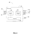
- FIG. 2 shows a buffer memory manager 200 and queue tail pointer 240 and queue head pointer 250 and free pointers 260 of a queue memory in the buffer manager operation 210 according to an embodiment of the present disclosure.
- the linked list pointers 240-260 may reside and be maintained in buffer manager 130 ( FIG. 1 ) under control of the processors 120 and 140 ( FIG. 1 ). Every queue has both a queue head pointer 250 and a queue tail pointer 240.
- the queue tail pointer 240 specifies the location of a write operation and the queue head pointer 250 specifies the location of a read operation.
- the queue head pointer 250 will shift along the queue for each new read operation.
- the queue tail pointer 240 will shift along the queue for each new write operation.
- the last queue tail pointer 240 will identify the last write operation in a cycle and the last queue head pointer 250 will identify the last read operation for a cycle.
- a new queue head pointer 250 and new tail pointer 240 are read.
- the token of the queue is received. After the token is received, information about the next head pointer can be accessed to be read and processed.
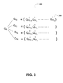
- FIG. 3 shows the parallel link-list configurations for a selected Q 0 which are populated in an order according to the sequential order of the tokens received.
- the pointer initially requested could be a queue head pointer or a queue tail pointer.
- Each Q 0 will be divided into 4 linked lists of Q 00 to Q 03 .
- a Q 00 would be divided into four memory locations Q 00 to Q 03 which are the lists of Q' 000 to Q' 002 shown in FIG 3 .
- a single link-list of Q 00 to Q 03 is subdivided further into 4 sub-link-lists of Q 00 to Q 03 .
- FIG. 4 illustrates the read cycle for each Q 0 which is N/4 for Q 00 .
- the first clocking cycle would include Q 00 , Q 01 ,Q 12 ,Q 00 .
- the next clocking cycle shifts N/4 commencing at Q 01 , Q 12 , Q 00 , Q 01 .
- the subsequent cycles each shift N/4 beginning with Q 12 .
- each subsequent read and write cycle are performed by N/4 time shifts. Therefore, in a particular Q 0 clocking time there are approximately up to 4 clocking register shifts of N/4 shortening the period distance of each register shift.
- a read request is executed and a token of data 505 is requested to be de-queued.
- a scheduler in response to the read request pops the top token of data in the selected queue.
- the requested token of data is placed by a buffer manager in the first available memory location of a set of memory banks, in this example, memory bank 0 is designated as the allocated address for the requested token of data.
- the head pointer 520 is selected by a link-list type manager application of the buffer manager to point to the requested token 505.
- the memory location is labeled Q00 0 by the buffer manager.
- An internal clocking application of the buffer manager allocates tuples of 4 memory locations for the tokens of data being requested.
- the start-point of the first clocking cycle Q 0 can be ascertained. This start-point is where the initial head pointer 510 is directed and again recognized after the initial token request 505 is read and processed.
- Each set of memory locations Q00 N is allocated up to 4 memory locations for the tokens of data being received from the selected queue.
- the next memory location is linked to Q00 0 via the tail pointer 515.
- the buffer manager sends the next read request and receives the second token of data from the queue.
- the second token of data is dynamically allocated an available memory location in Bank 1 which is designated Q00 1 .
- the next pointer received 515 from the buffer manager becomes the subsequent head pointer to memory location Q00 1 .
- the two tokens of data at the onset 515 and 550 are the initial request token of data Q00 0 515 and next token of data Q00 1 550 that was requested from the queue. Both tokens Q 000 515 and Q 001 550 are de-queued in a two-step process which involves initial reading of the Q 0 head pointer 510 and processing token of data from the Q00 0 location. After the processing of Q00 0 then the next tail pointer 515 can be reads and identified by the buffer manager. That is, once Q 0 is requested, Q00 0 is read; Q00 0 and then the data associated with Q00 0 is received, and the pathway to the next Q00 1 is identified.
- next tail pointer 550 for the pathway to Q00 2 and subsequent next pointer 565 are also identified. Additionally, once a request Q 0 has transpired, then the locations for sending the set of objects or data associated with Q 0 are known. Additionally, FIG 5A shows the other pathways daisy chained for the links for additional sets of tokens of data 525 and 570.
- the memory allocation Q03 0 is linked to Q03 1 and the subsequent tail pointer 535 pointing to address Q03 2 560 of bank 2 .
- the memory list allocation 570 of Address Q02 0 is connected to Q02 1 540 via its tail pointer. Additional allocations Q01 N 545 represents additional allocations in the memory lists in subsequent cycles.
- a tuple or set of 4 linked memory locations is created.
- the buffer manager begins with the next set of 4 linked locations and continues this process of creating tuples or sets of 4 memory locations until all the tokens of data are popped from the selected queue. If there is an odd number or not enough tokens of data to fill a set of 4 linked locations which may occur in the last set to be filled, then there will be blank locations in the list.
- the third memory location is similarly coupled to the second memory location Q00 1 by tail pointer 550.
- the tail pointer 550 is now the head pointer to the third memory location Q00 2 .
- the third memory location in bank 2 is designated by Q00 2 and each of the memory locations is dynamically designated and allocated in a round robin or circular fashion migrating across the multiple memory banks. This round robin process continues until the entire set of 4 memory locations are created and linked by head and tail pointers. This circular loop dictates the bandwidth output for much data in a given time can be forwarded out of the identified queue or how often data from a given queue can be dequeued in a network switching algorithm.
- Each bank list 510, 530, 555 includes a list of tokens of Q 000 to Q 03N linked to together in pathways so that each token can be associated with a set of Q 0 .
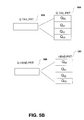
- FIG 5B illustrates in a block diagram the queue tail pointer 585 and related sub blocks of queue tail pointers 590 of Q 00 to Q 03 . Also shown is a block diagram of the queue head pointer 586 and the related sub-blocks of queue head pointers 595 of Q 00 to Q 03 . Each of the stacked sub blocks of queue tail pointers 590 and stacked sub blocks of queue tail pointers 595 are linked together in parallel link-lists represented in banks 1 and 2 of FIG. 5A .
- Fig. 6A and 6B illustrate in a block diagram an example of a queue 100 parallel link-list for a single queue consisting of 4 parallel link-lists. It should be noted that the underlying concept of the exemplary embodiment(s) of the present disclosure would not change if one or more of the parallel linked lists were added or removed from the exemplary embodiment of a dynamic linked list of FIG. 6A .
- FIG. 6A illustrates in a block diagram 600 an example of a queue 100 parallel link-list for a single queue 4 parallel link-lists: Q100-0 the first parallel linked list 605; Q100-1 the second parallel linked list 610; Q100-2 the third parallel linked list 615; and Q100-3 the fourth parallel linked list 620.
- Externally virtual couplings 625, 630 between the sub-lists of the blocks illustrate a first and second set of couplings in a loop configuration of linked lists Q100-0 1 to Q100-1 1 to Q100-2 1 to Q100-3 1 and back to Q100-0 1 ; and Q100-0 2 to Q100-1 2 to Q100-2 2 to Q100- 3 2 and back to Q100-0 2 .
- the couplings including tail and head pointers link together a set of 4 tokens of data with the last coupling 625, 630 serving as both the tail pointer of the last token of data in a set and the head pointer for the next token of data.
- the internal couplings Q100-0 1 to Q100-0 2 to Q100 3 represent individual parallel lists for individual token data sets in consecutive order. Hence, the last tail pointer of tokens of data set 1 is connected to the next token of data set 2 and the last tail pointer of set 1 serves as the first head pointer of tokens of data set 2.
- FIG. 6A the overall link-list round robin type cycle or loop process of enqueuing and populating the memory list allocations and de-queuing multiple sets of memory allocations of the 4 tokens of data of a set is shown.
- the coupling of the first set of 4 tokens of data between sub-lists 605, 610, 615, 620 are designated as "1-1-1-1" in FIG. 6A .
- the buffer manager relies on an internal counter application to track each set of 4 and a virtual table is created in buffer memory to store all the counter values with the associated head and tail pointers.
- the tokens of data can have additional pointers associated with additional data sets for each of the sets of 4 in the sub-lists allowing for data storage at external locations.
- the buffer manager Upon completion of the initial set of 4, the buffer manager increments its internal counter and designates the next set "2-2-2-2". This process is repeated until all tokens of data from the selected queue are enqueued or dequeued.
- the buffer manager using internal counter applications follows a FIFO type ordering of the blocks of sets of 4 and each set is further coupled in numerical order of sets of 1-2-3 as shown in the example of FIG. 6A .
- FIG. 6B illustrates in a block diagram an example of a queue list generated for a particular destination (not shown) in a port 4 and traffic class 4, of queue 100.
- parallel memory sub-lists 635, 640, 645, and 650 are shown parallel memory sub-lists 635, 640, 645, and 650.
- the queue tail pointer memory for Q100 is Q100-0 in memory sub-list 635 which is given as the current pointer 1000.
- the free pointer read from memory is 1100 and is written to queue tail memory for queue 100-0.
- the queue tail memory for Q100-0 has a current pointer of 1000 and a next pointer of 1100.
- Table 1.2 lists each of the "Qtail Req" with its current pointer and next pointer.
- Each of these queue tail requests and current and next pointer makes up internal parallel link-lists.
- the memory allocations in Q100-0 are random and dynamically selected on availability. Hence, the ordering in the memory list is changed upon availability of memory locations.
- a dynamic list generated is shown in Table 1.2 below, where during the enqueuer process, the buffer manager allocates for the first set of 4 of tokens of data a current pointer 1000 and then next pointer 1100 for the next set of 4 of tokens of data.
- An internal counter is shown in the FIG. 6B of the tail pointer 1000 and the counter 0.
- the next pointer for the token of data in the first set is shown by a coupling of a tail pointer from 1000-0 to 2000-1.
- the counter is update to 1 and the current pointer in the sub list Q100-1 is 2000.
- sublist Q100-2 the current pointer is 3000 with the counter 2 and in sub list Q100-3, the current pointer is 4000 with counter 3.
- Each of the sub lists 635-650 is allocated with current pointers as the buffer manager migrates to each list and updates its internal counter creating a set of head and tail pointers for each set of 4 tokens of data.
- the buffer manager After migrating through each of the sub-lists, the buffer manager returns 655, 660 with a free pointer as the next current pointer for the next set of tokens of data.
- this circular or round robin approach all the sub-lists are utilized for storing the tokens of data in sets of 4 and the last tail pointer of each set becomes the subsequent head pointer of the next set.
- the counter values of the initial Q100-0 link-list 635 are designated in sets of 4 of 0, 4, 8, etc... corresponding to sets of pointers allocated to each set of tokens of data.
- Table 1.1 Enqueue and Buffer manager Interaction Qtail Req-100-0->current pointer-1000, next pointer -1100 Qtail Req-100-1->current pointer-2000, next pointer -2100 Qtail Req-100-2->current pointer-3000, next pointer -3100 Qtail Req-100-3->current pointer-4000, next pointer -4100 Qtail Req-100-4->current pointer-1100, next pointer -1200 Qtail Req-100-5->current pointer-2100, next pointer -2200 Qtail Req-100-6->current pointer-3100, next pointer -3200 Qtail Req-100-7->current pointer-4100, next pointer -4200 Qtail Req-100-8->current pointer-1200, next pointer -1300
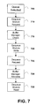
- FIG. 7 is a flowchart illustrating an exemplary process performed bythe buffer manager operation of FIG. 2 . Further, a representation of continuous packet traffic for the queue 100 according to the steps of the flowchart of FIG. 7 .
- a queue is selected based upon the destination port and class of traffic associated with the data.
- the enqueue module 120 (of FIG. 1 ) requests the buffer manager 130 (of FIG. 1 ) for the pointer to store the data in the buffer memory 150 (of FIG. 1 ). For example, with respect to the identified queue 100 in FIGs. 6A and 6B the enqueue module would request pointer locations for queue 100.
- Step 715 the buffer manager checks the queue tail pointer memory for the identified queue and sets the current pointer to his location. Additionally, the buffer manager pops up an additional one free pointer from the free pointer memory and writes this into the queue tail pointer memory and also identifies this free pointer as the next pointer to the enqueue module
- the enqueue module uses the current pointer to write the token and next location in the buffer memory.
- the enqueue module uses location 1000 to write the token and 1100 as the next memory location as shown in table 1.1. Additionally, for the next queue tail request 100-1, the enqueue module uses the current pointer at memory location 3000 and the next pointer is at memory location 3100.
- the table 1.1 illustrates the subsequent queue tail requests and current pointer and next pointer locations.
- the dequeue module requests the queue head pointer for the queue from the buffer manager.
- the dequeue module requests for head pointer 1000 for queue 100 to be sent to the buffer manager.
- the buffer manager allocates the head pointer value 1000 for the requested queue.
- Step 635 illustrates the dequeue module operation when the dequeue module reads the packet and next pointer from the buffer memory and then forwards the next pointer as the head pointer update to the buffer manager.
- the dequeue module will read from location 1000 in the buffer from where it receives the token and next pointer 1100.
- the dequeue module sends 1100 as head pointer update request for queue 100.
- Pointer 1000 is now the free pointer and the dequeue module forwards the free pointer to the buffer manager. (See table 1.2 for Dequeue operation below).
- the dequeue module commences a scheduled dequeue operation of queue 100, the operation is performed by a scheduler in 4 clocking cycles each Q 0 split equally across the multiple queues.
- the scheduler requests the head pointer information of queue 100, 101, 102, and 103 sequentially, so as to perform the dequeuer operation in the priority of the scheduler requests.
- the overall Q 0 when dequeuing the queue is performed by the scheduler in the scheduled queue 100 every 4 clocks which can be viewed as the Q 0 of accessing data linked together over 4 different parallel link-lists.
- the dequeue operation can occur up to a maximum speed of 16 clocks in a cycle.
- the parallel link-list dequeuing can be increased from 4 to 8 and upward.
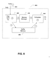
- FIG. 8 is a block diagram similar to FIG. 2 but illustrates the steps of the enqueuing and de-queuing operations.
- incoming tokens (1) are received to be classified by en-queue module 820.
- output (3) requests a new queue tail pointer from the buffer memory 830.
- the queue tail memory for the parallel link-list (2) is sent to the memory (4) for a write operation into the buffer memory 850.
- the token data is written into the buffer memory 850.
- the scheduler 840 chooses a Q(Q 0 ) (5) and request queue head pointer (6) for the parallel link-list.
- the buffer manager reads the queue head pointer and uses this head pointer as the updated head pointer and then writes the updated head pointer to the parallel link-list.
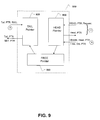
- FIG. 9 is an illustration an exemplary process performed by a buffer manager when an incoming token is received and classified to a Q 0 according to an embodiment of the present disclosure.
- a request for a new queue tail pointer (3) is sent to queue tail pointer module 920.
- Queue tail pointers for the parallel link-list are generated with each request and when the token is received a write operation is performed for the token into the buffer memory.
- a request is made for a queue head pointer (6) to be sent to the queue head pointer module 930.
- the queue head pointers for the parallel link-list are sent from each of the parallel link-lists.
- the requested queue head pointer is read and the token associated with the head pointer is forwarded out (8) with the queue updated head pointer and the now free old pointer.
- the routing process according to the present disclosure advantageously offers increased thorough-put for limited buffer space allocation for the enqueue and dequeue operations thereby reducing latency time experienced at this bottleneck operational step by the buffer manager.
- the tokens of data can be retrieved and transmitted faster without significant changes in the physical buffer configurations while reducing the overall latency times incurred in such enqueuing and dequeuing operations.
- the circuitry in the router can be implemented as application specific integrated circuits (ASIC), application-specific standard parts (ASSPs), System-on-Chip (SoC), field-programmable gate arrays (FPGAs), etc. Further, it will be appreciated that the router may include various other functions and components that are well known in the art.
- ASIC application specific integrated circuits
- ASSPs application-specific standard parts
- SoC System-on-Chip
- FPGAs field-programmable gate arrays
Landscapes
- Engineering & Computer Science (AREA)
- Computer Networks & Wireless Communication (AREA)
- Signal Processing (AREA)
- Data Exchanges In Wide-Area Networks (AREA)
- Theoretical Computer Science (AREA)
- Physics & Mathematics (AREA)
- General Engineering & Computer Science (AREA)
- General Physics & Mathematics (AREA)
Applications Claiming Priority (1)
| Application Number | Priority Date | Filing Date | Title |
|---|---|---|---|
| US14/675,450 US10484311B2 (en) | 2015-03-31 | 2015-03-31 | Method and apparatus for using multiple linked memory lists |
Publications (1)
| Publication Number | Publication Date |
|---|---|
| EP3076621A1 true EP3076621A1 (en) | 2016-10-05 |
Family
ID=53496442
Family Applications (1)
| Application Number | Title | Priority Date | Filing Date |
|---|---|---|---|
| EP15173183.3A Withdrawn EP3076621A1 (en) | 2015-03-31 | 2015-06-22 | Method and apparatus for using multiple linked memory lists |
Country Status (6)
| Country | Link |
|---|---|
| US (2) | US10484311B2 (enExample) |
| EP (1) | EP3076621A1 (enExample) |
| JP (1) | JP6535253B2 (enExample) |
| KR (1) | KR102082020B1 (enExample) |
| CN (2) | CN106209679B (enExample) |
| TW (1) | TWI684344B (enExample) |
Cited By (1)
| Publication number | Priority date | Publication date | Assignee | Title |
|---|---|---|---|---|
| WO2022139808A1 (en) * | 2020-12-22 | 2022-06-30 | Futurewei Technologies, Inc. | Low-latency software defined wide area network architecture |
Families Citing this family (18)
| Publication number | Priority date | Publication date | Assignee | Title |
|---|---|---|---|---|
| CN102984083B (zh) * | 2012-11-19 | 2018-07-24 | 南京中兴新软件有限责任公司 | 队列管理方法及装置 |
| US10484311B2 (en) * | 2015-03-31 | 2019-11-19 | Cavium, Llc | Method and apparatus for using multiple linked memory lists |
| CN105162724B (zh) * | 2015-07-30 | 2018-06-26 | 华为技术有限公司 | 一种数据入队与出队方法及队列管理单元 |
| US10833843B1 (en) | 2015-12-03 | 2020-11-10 | United Services Automobile Association (USAA0 | Managing blockchain access |
| KR101948988B1 (ko) * | 2016-12-12 | 2019-02-15 | 주식회사 엘지유플러스 | 캐시를 이용한 파일 실행 방법 및 그 장치 |
| CN112087394B (zh) * | 2017-02-17 | 2025-01-14 | 华为技术有限公司 | 一种报文处理方法及装置 |
| US10402320B1 (en) * | 2018-02-27 | 2019-09-03 | Oracle International Corporation | Verifying the validity of a transition from a current tail template to a new tail template for a fused object |
| US10901887B2 (en) | 2018-05-17 | 2021-01-26 | International Business Machines Corporation | Buffered freepointer management memory system |
| CN112311696B (zh) * | 2019-07-26 | 2022-06-10 | 瑞昱半导体股份有限公司 | 网络封包接收装置及方法 |
| US11240151B2 (en) * | 2019-12-10 | 2022-02-01 | Juniper Networks, Inc. | Combined input and output queue for packet forwarding in network devices |
| CN113132449A (zh) * | 2020-01-16 | 2021-07-16 | 京东方科技集团股份有限公司 | 一种调度方法、装置及设备 |
| US11437081B2 (en) | 2020-08-12 | 2022-09-06 | Taiwan Semiconductor Manufacturing Company Limited | Buffer control of multiple memory banks |
| US11043250B1 (en) * | 2020-08-12 | 2021-06-22 | Taiwan Semiconductor Manufacturing Company Limited | Buffer control of multiple memory banks |
| CN112559400B (zh) * | 2020-12-03 | 2024-07-09 | 南京盛科通信有限公司 | 多级调度装置、方法、网络芯片及计算机可读存储介质 |
| KR20220109213A (ko) | 2021-01-28 | 2022-08-04 | 하준우 | 발코니 문 |
| US20240126595A1 (en) * | 2022-10-13 | 2024-04-18 | Cortina Access, Inc. | Method and apparatus for managing a queue and queue management device |
| KR102789200B1 (ko) * | 2023-11-13 | 2025-03-31 | 리벨리온 주식회사 | 메모리 내 멀티 데이터 스트림을 단일 데이터 버퍼에 버퍼링하기 위한 직접 메모리 접근 장치 및 그의 동작 방법 |
| CN119046186B (zh) * | 2024-10-30 | 2025-03-14 | 合肥康芯威存储技术有限公司 | 一种存储器及缓存块的优化方法 |
Citations (3)
| Publication number | Priority date | Publication date | Assignee | Title |
|---|---|---|---|---|
| US20090257441A1 (en) * | 2008-04-15 | 2009-10-15 | Fujitsu Limited | Packet forwarding apparatus and method for discarding packets |
| US20110016284A1 (en) * | 2009-07-16 | 2011-01-20 | Shreeharsha Balan | Memory Management in Network Processors |
| US20120127860A1 (en) * | 2010-11-18 | 2012-05-24 | Cisco Technology, Inc. | Dynamic Flow Redistribution for Head of Line Blocking Avoidance |
Family Cites Families (12)
| Publication number | Priority date | Publication date | Assignee | Title |
|---|---|---|---|---|
| JP3117133B2 (ja) | 1999-02-16 | 2000-12-11 | 日本電気株式会社 | フレーム組み立て回路及びフレーム組み立て方法 |
| US7627870B1 (en) * | 2001-04-28 | 2009-12-01 | Cisco Technology, Inc. | Method and apparatus for a data structure comprising a hierarchy of queues or linked list data structures |
| US7003597B2 (en) * | 2003-07-09 | 2006-02-21 | International Business Machines Corporation | Dynamic reallocation of data stored in buffers based on packet size |
| US7290110B2 (en) * | 2003-09-11 | 2007-10-30 | International Business Machines Corporation | System and method of squeezing memory slabs empty |
| US7796627B2 (en) | 2004-08-12 | 2010-09-14 | Broadcom Corporation | Apparatus and system for coupling and decoupling initiator devices to a network using an arbitrated loop without disrupting the network |
| US8650364B2 (en) * | 2008-05-28 | 2014-02-11 | Vixs Systems, Inc. | Processing system with linked-list based prefetch buffer and methods for use therewith |
| CN101605100B (zh) * | 2009-07-15 | 2012-04-25 | 华为技术有限公司 | 队列存储空间的管理方法和设备 |
| JP2011254149A (ja) | 2010-05-31 | 2011-12-15 | Nippon Telegr & Teleph Corp <Ntt> | 情報処理装置、情報処理方法およびプログラム |
| CN102437929B (zh) * | 2011-12-16 | 2014-05-07 | 华为技术有限公司 | 队列管理中的数据出队方法及装置 |
| US9438527B2 (en) * | 2012-05-24 | 2016-09-06 | Marvell World Trade Ltd. | Flexible queues in a network switch |
| US9674086B2 (en) * | 2013-11-05 | 2017-06-06 | Cisco Technology, Inc. | Work conserving schedular based on ranking |
| US10484311B2 (en) * | 2015-03-31 | 2019-11-19 | Cavium, Llc | Method and apparatus for using multiple linked memory lists |
-
2015
- 2015-03-31 US US14/675,450 patent/US10484311B2/en active Active
- 2015-05-14 KR KR1020150067244A patent/KR102082020B1/ko active Active
- 2015-05-29 CN CN201510290966.8A patent/CN106209679B/zh active Active
- 2015-05-29 CN CN202110526734.3A patent/CN113242186B/zh active Active
- 2015-06-22 EP EP15173183.3A patent/EP3076621A1/en not_active Withdrawn
- 2015-07-31 TW TW104124865A patent/TWI684344B/zh active
- 2015-08-31 JP JP2015170003A patent/JP6535253B2/ja active Active
-
2019
- 2019-10-07 US US16/594,962 patent/US11082366B2/en active Active
Patent Citations (3)
| Publication number | Priority date | Publication date | Assignee | Title |
|---|---|---|---|---|
| US20090257441A1 (en) * | 2008-04-15 | 2009-10-15 | Fujitsu Limited | Packet forwarding apparatus and method for discarding packets |
| US20110016284A1 (en) * | 2009-07-16 | 2011-01-20 | Shreeharsha Balan | Memory Management in Network Processors |
| US20120127860A1 (en) * | 2010-11-18 | 2012-05-24 | Cisco Technology, Inc. | Dynamic Flow Redistribution for Head of Line Blocking Avoidance |
Cited By (1)
| Publication number | Priority date | Publication date | Assignee | Title |
|---|---|---|---|---|
| WO2022139808A1 (en) * | 2020-12-22 | 2022-06-30 | Futurewei Technologies, Inc. | Low-latency software defined wide area network architecture |
Also Published As
| Publication number | Publication date |
|---|---|
| US11082366B2 (en) | 2021-08-03 |
| KR20160117108A (ko) | 2016-10-10 |
| CN113242186B (zh) | 2024-12-24 |
| JP2016195375A (ja) | 2016-11-17 |
| US10484311B2 (en) | 2019-11-19 |
| TW201703475A (zh) | 2017-01-16 |
| JP6535253B2 (ja) | 2019-06-26 |
| US20160294735A1 (en) | 2016-10-06 |
| KR102082020B1 (ko) | 2020-02-26 |
| CN113242186A (zh) | 2021-08-10 |
| US20200044989A1 (en) | 2020-02-06 |
| TWI684344B (zh) | 2020-02-01 |
| CN106209679B (zh) | 2021-05-11 |
| CN106209679A (zh) | 2016-12-07 |
Similar Documents
| Publication | Publication Date | Title |
|---|---|---|
| US11082366B2 (en) | Method and apparatus for using multiple linked memory lists | |
| CN1736068B (zh) | 流量管理结构体系 | |
| US7555579B2 (en) | Implementing FIFOs in shared memory using linked lists and interleaved linked lists | |
| US6715046B1 (en) | Method and apparatus for reading from and writing to storage using acknowledged phases of sets of data | |
| US20050219564A1 (en) | Image forming device, pattern formation method and storage medium storing its program | |
| US20050220112A1 (en) | Distributed packet processing with ordered locks to maintain requisite packet orderings | |
| CA2543246C (en) | Using ordered locking mechanisms to maintain sequences of items such as packets | |
| US11310164B1 (en) | Method and apparatus for resource allocation | |
| US7529224B2 (en) | Scheduler, network processor, and methods for weighted best effort scheduling | |
| US8223788B1 (en) | Method and system for queuing descriptors | |
| CN108351838A (zh) | 使用聚合存储器管理单元(mmu)提供存储器管理功能 | |
| CN110519180B (zh) | 网卡虚拟化队列调度方法及系统 | |
| US9148270B2 (en) | Method and apparatus for handling data flow in a multi-chip environment using an interchip interface | |
| US7483377B2 (en) | Method and apparatus to prioritize network traffic | |
| US7583678B1 (en) | Methods and apparatus for scheduling entities using a primary scheduling mechanism such as calendar scheduling filled in with entities from a secondary scheduling mechanism | |
| HK1227576A1 (en) | Method and apparatus for using multiple linked memory lists | |
| US7603539B2 (en) | Systems and methods for multi-frame control blocks | |
| HK1227576B (zh) | 用於使用多个链接的存储器列表的方法及装置 | |
| US20250233832A1 (en) | Multi-datapath support for low latency traffic manager | |
| CN121056396A (zh) | 数据包转发方法、网关设备、存储介质和程序 |
Legal Events
| Date | Code | Title | Description |
|---|---|---|---|
| PUAI | Public reference made under article 153(3) epc to a published international application that has entered the european phase |
Free format text: ORIGINAL CODE: 0009012 |
|
| AK | Designated contracting states |
Kind code of ref document: A1 Designated state(s): AL AT BE BG CH CY CZ DE DK EE ES FI FR GB GR HR HU IE IS IT LI LT LU LV MC MK MT NL NO PL PT RO RS SE SI SK SM TR |
|
| AX | Request for extension of the european patent |
Extension state: BA ME |
|
| STAA | Information on the status of an ep patent application or granted ep patent |
Free format text: STATUS: THE APPLICATION IS DEEMED TO BE WITHDRAWN |
|
| 18D | Application deemed to be withdrawn |
Effective date: 20170406 |
|
| RAP1 | Party data changed (applicant data changed or rights of an application transferred) |
Owner name: CAVIUM, INC. |