EP3075595A2 - A multi-source energy storage system and method for energy management and control - Google Patents
A multi-source energy storage system and method for energy management and control Download PDFInfo
- Publication number
- EP3075595A2 EP3075595A2 EP16162905.0A EP16162905A EP3075595A2 EP 3075595 A2 EP3075595 A2 EP 3075595A2 EP 16162905 A EP16162905 A EP 16162905A EP 3075595 A2 EP3075595 A2 EP 3075595A2
- Authority
- EP
- European Patent Office
- Prior art keywords
- energy storage
- storage system
- converter
- electrical load
- source
- Prior art date
- Legal status (The legal status is an assumption and is not a legal conclusion. Google has not performed a legal analysis and makes no representation as to the accuracy of the status listed.)
- Granted
Links
Images



Classifications
-
- B—PERFORMING OPERATIONS; TRANSPORTING
- B60—VEHICLES IN GENERAL
- B60L—PROPULSION OF ELECTRICALLY-PROPELLED VEHICLES; SUPPLYING ELECTRIC POWER FOR AUXILIARY EQUIPMENT OF ELECTRICALLY-PROPELLED VEHICLES; ELECTRODYNAMIC BRAKE SYSTEMS FOR VEHICLES IN GENERAL; MAGNETIC SUSPENSION OR LEVITATION FOR VEHICLES; MONITORING OPERATING VARIABLES OF ELECTRICALLY-PROPELLED VEHICLES; ELECTRIC SAFETY DEVICES FOR ELECTRICALLY-PROPELLED VEHICLES
- B60L53/00—Methods of charging batteries, specially adapted for electric vehicles; Charging stations or on-board charging equipment therefor; Exchange of energy storage elements in electric vehicles
- B60L53/20—Methods of charging batteries, specially adapted for electric vehicles; Charging stations or on-board charging equipment therefor; Exchange of energy storage elements in electric vehicles characterised by converters located in the vehicle
-
- B—PERFORMING OPERATIONS; TRANSPORTING
- B60—VEHICLES IN GENERAL
- B60L—PROPULSION OF ELECTRICALLY-PROPELLED VEHICLES; SUPPLYING ELECTRIC POWER FOR AUXILIARY EQUIPMENT OF ELECTRICALLY-PROPELLED VEHICLES; ELECTRODYNAMIC BRAKE SYSTEMS FOR VEHICLES IN GENERAL; MAGNETIC SUSPENSION OR LEVITATION FOR VEHICLES; MONITORING OPERATING VARIABLES OF ELECTRICALLY-PROPELLED VEHICLES; ELECTRIC SAFETY DEVICES FOR ELECTRICALLY-PROPELLED VEHICLES
- B60L58/00—Methods or circuit arrangements for monitoring or controlling batteries or fuel cells, specially adapted for electric vehicles
- B60L58/10—Methods or circuit arrangements for monitoring or controlling batteries or fuel cells, specially adapted for electric vehicles for monitoring or controlling batteries
- B60L58/18—Methods or circuit arrangements for monitoring or controlling batteries or fuel cells, specially adapted for electric vehicles for monitoring or controlling batteries of two or more battery modules
- B60L58/20—Methods or circuit arrangements for monitoring or controlling batteries or fuel cells, specially adapted for electric vehicles for monitoring or controlling batteries of two or more battery modules having different nominal voltages
-
- B—PERFORMING OPERATIONS; TRANSPORTING
- B60—VEHICLES IN GENERAL
- B60L—PROPULSION OF ELECTRICALLY-PROPELLED VEHICLES; SUPPLYING ELECTRIC POWER FOR AUXILIARY EQUIPMENT OF ELECTRICALLY-PROPELLED VEHICLES; ELECTRODYNAMIC BRAKE SYSTEMS FOR VEHICLES IN GENERAL; MAGNETIC SUSPENSION OR LEVITATION FOR VEHICLES; MONITORING OPERATING VARIABLES OF ELECTRICALLY-PROPELLED VEHICLES; ELECTRIC SAFETY DEVICES FOR ELECTRICALLY-PROPELLED VEHICLES
- B60L50/00—Electric propulsion with power supplied within the vehicle
- B60L50/10—Electric propulsion with power supplied within the vehicle using propulsion power supplied by engine-driven generators, e.g. generators driven by combustion engines
-
- B—PERFORMING OPERATIONS; TRANSPORTING
- B60—VEHICLES IN GENERAL
- B60L—PROPULSION OF ELECTRICALLY-PROPELLED VEHICLES; SUPPLYING ELECTRIC POWER FOR AUXILIARY EQUIPMENT OF ELECTRICALLY-PROPELLED VEHICLES; ELECTRODYNAMIC BRAKE SYSTEMS FOR VEHICLES IN GENERAL; MAGNETIC SUSPENSION OR LEVITATION FOR VEHICLES; MONITORING OPERATING VARIABLES OF ELECTRICALLY-PROPELLED VEHICLES; ELECTRIC SAFETY DEVICES FOR ELECTRICALLY-PROPELLED VEHICLES
- B60L50/00—Electric propulsion with power supplied within the vehicle
- B60L50/50—Electric propulsion with power supplied within the vehicle using propulsion power supplied by batteries or fuel cells
- B60L50/60—Electric propulsion with power supplied within the vehicle using propulsion power supplied by batteries or fuel cells using power supplied by batteries
- B60L50/66—Arrangements of batteries
-
- B—PERFORMING OPERATIONS; TRANSPORTING
- B60—VEHICLES IN GENERAL
- B60L—PROPULSION OF ELECTRICALLY-PROPELLED VEHICLES; SUPPLYING ELECTRIC POWER FOR AUXILIARY EQUIPMENT OF ELECTRICALLY-PROPELLED VEHICLES; ELECTRODYNAMIC BRAKE SYSTEMS FOR VEHICLES IN GENERAL; MAGNETIC SUSPENSION OR LEVITATION FOR VEHICLES; MONITORING OPERATING VARIABLES OF ELECTRICALLY-PROPELLED VEHICLES; ELECTRIC SAFETY DEVICES FOR ELECTRICALLY-PROPELLED VEHICLES
- B60L50/00—Electric propulsion with power supplied within the vehicle
- B60L50/50—Electric propulsion with power supplied within the vehicle using propulsion power supplied by batteries or fuel cells
- B60L50/70—Electric propulsion with power supplied within the vehicle using propulsion power supplied by batteries or fuel cells using power supplied by fuel cells
- B60L50/71—Arrangement of fuel cells within vehicles specially adapted for electric vehicles
-
- B—PERFORMING OPERATIONS; TRANSPORTING
- B60—VEHICLES IN GENERAL
- B60L—PROPULSION OF ELECTRICALLY-PROPELLED VEHICLES; SUPPLYING ELECTRIC POWER FOR AUXILIARY EQUIPMENT OF ELECTRICALLY-PROPELLED VEHICLES; ELECTRODYNAMIC BRAKE SYSTEMS FOR VEHICLES IN GENERAL; MAGNETIC SUSPENSION OR LEVITATION FOR VEHICLES; MONITORING OPERATING VARIABLES OF ELECTRICALLY-PROPELLED VEHICLES; ELECTRIC SAFETY DEVICES FOR ELECTRICALLY-PROPELLED VEHICLES
- B60L53/00—Methods of charging batteries, specially adapted for electric vehicles; Charging stations or on-board charging equipment therefor; Exchange of energy storage elements in electric vehicles
- B60L53/50—Charging stations characterised by energy-storage or power-generation means
- B60L53/53—Batteries
-
- B—PERFORMING OPERATIONS; TRANSPORTING
- B60—VEHICLES IN GENERAL
- B60L—PROPULSION OF ELECTRICALLY-PROPELLED VEHICLES; SUPPLYING ELECTRIC POWER FOR AUXILIARY EQUIPMENT OF ELECTRICALLY-PROPELLED VEHICLES; ELECTRODYNAMIC BRAKE SYSTEMS FOR VEHICLES IN GENERAL; MAGNETIC SUSPENSION OR LEVITATION FOR VEHICLES; MONITORING OPERATING VARIABLES OF ELECTRICALLY-PROPELLED VEHICLES; ELECTRIC SAFETY DEVICES FOR ELECTRICALLY-PROPELLED VEHICLES
- B60L58/00—Methods or circuit arrangements for monitoring or controlling batteries or fuel cells, specially adapted for electric vehicles
- B60L58/10—Methods or circuit arrangements for monitoring or controlling batteries or fuel cells, specially adapted for electric vehicles for monitoring or controlling batteries
-
- H—ELECTRICITY
- H02—GENERATION; CONVERSION OR DISTRIBUTION OF ELECTRIC POWER
- H02M—APPARATUS FOR CONVERSION BETWEEN AC AND AC, BETWEEN AC AND DC, OR BETWEEN DC AND DC, AND FOR USE WITH MAINS OR SIMILAR POWER SUPPLY SYSTEMS; CONVERSION OF DC OR AC INPUT POWER INTO SURGE OUTPUT POWER; CONTROL OR REGULATION THEREOF
- H02M3/00—Conversion of DC power input into DC power output
- H02M3/02—Conversion of DC power input into DC power output without intermediate conversion into AC
- H02M3/04—Conversion of DC power input into DC power output without intermediate conversion into AC by static converters
- H02M3/10—Conversion of DC power input into DC power output without intermediate conversion into AC by static converters using discharge tubes with control electrode or semiconductor devices with control electrode
- H02M3/145—Conversion of DC power input into DC power output without intermediate conversion into AC by static converters using discharge tubes with control electrode or semiconductor devices with control electrode using devices of a triode or transistor type requiring continuous application of a control signal
- H02M3/155—Conversion of DC power input into DC power output without intermediate conversion into AC by static converters using discharge tubes with control electrode or semiconductor devices with control electrode using devices of a triode or transistor type requiring continuous application of a control signal using semiconductor devices only
- H02M3/156—Conversion of DC power input into DC power output without intermediate conversion into AC by static converters using discharge tubes with control electrode or semiconductor devices with control electrode using devices of a triode or transistor type requiring continuous application of a control signal using semiconductor devices only with automatic control of output voltage or current, e.g. switching regulators
- H02M3/158—Conversion of DC power input into DC power output without intermediate conversion into AC by static converters using discharge tubes with control electrode or semiconductor devices with control electrode using devices of a triode or transistor type requiring continuous application of a control signal using semiconductor devices only with automatic control of output voltage or current, e.g. switching regulators including plural semiconductor devices as final control devices for a single load
-
- B—PERFORMING OPERATIONS; TRANSPORTING
- B60—VEHICLES IN GENERAL
- B60L—PROPULSION OF ELECTRICALLY-PROPELLED VEHICLES; SUPPLYING ELECTRIC POWER FOR AUXILIARY EQUIPMENT OF ELECTRICALLY-PROPELLED VEHICLES; ELECTRODYNAMIC BRAKE SYSTEMS FOR VEHICLES IN GENERAL; MAGNETIC SUSPENSION OR LEVITATION FOR VEHICLES; MONITORING OPERATING VARIABLES OF ELECTRICALLY-PROPELLED VEHICLES; ELECTRIC SAFETY DEVICES FOR ELECTRICALLY-PROPELLED VEHICLES
- B60L2210/00—Converter types
- B60L2210/10—DC to DC converters
-
- B—PERFORMING OPERATIONS; TRANSPORTING
- B60—VEHICLES IN GENERAL
- B60L—PROPULSION OF ELECTRICALLY-PROPELLED VEHICLES; SUPPLYING ELECTRIC POWER FOR AUXILIARY EQUIPMENT OF ELECTRICALLY-PROPELLED VEHICLES; ELECTRODYNAMIC BRAKE SYSTEMS FOR VEHICLES IN GENERAL; MAGNETIC SUSPENSION OR LEVITATION FOR VEHICLES; MONITORING OPERATING VARIABLES OF ELECTRICALLY-PROPELLED VEHICLES; ELECTRIC SAFETY DEVICES FOR ELECTRICALLY-PROPELLED VEHICLES
- B60L2240/00—Control parameters of input or output; Target parameters
- B60L2240/40—Drive Train control parameters
- B60L2240/44—Drive Train control parameters related to combustion engines
-
- H—ELECTRICITY
- H02—GENERATION; CONVERSION OR DISTRIBUTION OF ELECTRIC POWER
- H02J—ELECTRIC POWER NETWORKS; CIRCUIT ARRANGEMENTS OR SYSTEMS FOR SUPPLYING OR DISTRIBUTING ELECTRIC POWER; SYSTEMS FOR STORING ELECTRIC ENERGY
- H02J3/00—Circuit arrangements for AC mains or AC distribution networks
- H02J3/28—Arrangements for balancing of the load in networks by storage of energy
-
- Y—GENERAL TAGGING OF NEW TECHNOLOGICAL DEVELOPMENTS; GENERAL TAGGING OF CROSS-SECTIONAL TECHNOLOGIES SPANNING OVER SEVERAL SECTIONS OF THE IPC; TECHNICAL SUBJECTS COVERED BY FORMER USPC CROSS-REFERENCE ART COLLECTIONS [XRACs] AND DIGESTS
- Y02—TECHNOLOGIES OR APPLICATIONS FOR MITIGATION OR ADAPTATION AGAINST CLIMATE CHANGE
- Y02T—CLIMATE CHANGE MITIGATION TECHNOLOGIES RELATED TO TRANSPORTATION
- Y02T10/00—Road transport of goods or passengers
- Y02T10/60—Other road transportation technologies with climate change mitigation effect
- Y02T10/62—Hybrid vehicles
-
- Y—GENERAL TAGGING OF NEW TECHNOLOGICAL DEVELOPMENTS; GENERAL TAGGING OF CROSS-SECTIONAL TECHNOLOGIES SPANNING OVER SEVERAL SECTIONS OF THE IPC; TECHNICAL SUBJECTS COVERED BY FORMER USPC CROSS-REFERENCE ART COLLECTIONS [XRACs] AND DIGESTS
- Y02—TECHNOLOGIES OR APPLICATIONS FOR MITIGATION OR ADAPTATION AGAINST CLIMATE CHANGE
- Y02T—CLIMATE CHANGE MITIGATION TECHNOLOGIES RELATED TO TRANSPORTATION
- Y02T10/00—Road transport of goods or passengers
- Y02T10/60—Other road transportation technologies with climate change mitigation effect
- Y02T10/70—Energy storage systems for electromobility, e.g. batteries
-
- Y—GENERAL TAGGING OF NEW TECHNOLOGICAL DEVELOPMENTS; GENERAL TAGGING OF CROSS-SECTIONAL TECHNOLOGIES SPANNING OVER SEVERAL SECTIONS OF THE IPC; TECHNICAL SUBJECTS COVERED BY FORMER USPC CROSS-REFERENCE ART COLLECTIONS [XRACs] AND DIGESTS
- Y02—TECHNOLOGIES OR APPLICATIONS FOR MITIGATION OR ADAPTATION AGAINST CLIMATE CHANGE
- Y02T—CLIMATE CHANGE MITIGATION TECHNOLOGIES RELATED TO TRANSPORTATION
- Y02T10/00—Road transport of goods or passengers
- Y02T10/60—Other road transportation technologies with climate change mitigation effect
- Y02T10/7072—Electromobility specific charging systems or methods for batteries, ultracapacitors, supercapacitors or double-layer capacitors
-
- Y—GENERAL TAGGING OF NEW TECHNOLOGICAL DEVELOPMENTS; GENERAL TAGGING OF CROSS-SECTIONAL TECHNOLOGIES SPANNING OVER SEVERAL SECTIONS OF THE IPC; TECHNICAL SUBJECTS COVERED BY FORMER USPC CROSS-REFERENCE ART COLLECTIONS [XRACs] AND DIGESTS
- Y02—TECHNOLOGIES OR APPLICATIONS FOR MITIGATION OR ADAPTATION AGAINST CLIMATE CHANGE
- Y02T—CLIMATE CHANGE MITIGATION TECHNOLOGIES RELATED TO TRANSPORTATION
- Y02T10/00—Road transport of goods or passengers
- Y02T10/60—Other road transportation technologies with climate change mitigation effect
- Y02T10/72—Electric energy management in electromobility
-
- Y—GENERAL TAGGING OF NEW TECHNOLOGICAL DEVELOPMENTS; GENERAL TAGGING OF CROSS-SECTIONAL TECHNOLOGIES SPANNING OVER SEVERAL SECTIONS OF THE IPC; TECHNICAL SUBJECTS COVERED BY FORMER USPC CROSS-REFERENCE ART COLLECTIONS [XRACs] AND DIGESTS
- Y02—TECHNOLOGIES OR APPLICATIONS FOR MITIGATION OR ADAPTATION AGAINST CLIMATE CHANGE
- Y02T—CLIMATE CHANGE MITIGATION TECHNOLOGIES RELATED TO TRANSPORTATION
- Y02T90/00—Enabling technologies or technologies with a potential or indirect contribution to GHG emissions mitigation
- Y02T90/10—Technologies relating to charging of electric vehicles
- Y02T90/12—Electric charging stations
-
- Y—GENERAL TAGGING OF NEW TECHNOLOGICAL DEVELOPMENTS; GENERAL TAGGING OF CROSS-SECTIONAL TECHNOLOGIES SPANNING OVER SEVERAL SECTIONS OF THE IPC; TECHNICAL SUBJECTS COVERED BY FORMER USPC CROSS-REFERENCE ART COLLECTIONS [XRACs] AND DIGESTS
- Y02—TECHNOLOGIES OR APPLICATIONS FOR MITIGATION OR ADAPTATION AGAINST CLIMATE CHANGE
- Y02T—CLIMATE CHANGE MITIGATION TECHNOLOGIES RELATED TO TRANSPORTATION
- Y02T90/00—Enabling technologies or technologies with a potential or indirect contribution to GHG emissions mitigation
- Y02T90/10—Technologies relating to charging of electric vehicles
- Y02T90/14—Plug-in electric vehicles
-
- Y—GENERAL TAGGING OF NEW TECHNOLOGICAL DEVELOPMENTS; GENERAL TAGGING OF CROSS-SECTIONAL TECHNOLOGIES SPANNING OVER SEVERAL SECTIONS OF THE IPC; TECHNICAL SUBJECTS COVERED BY FORMER USPC CROSS-REFERENCE ART COLLECTIONS [XRACs] AND DIGESTS
- Y02—TECHNOLOGIES OR APPLICATIONS FOR MITIGATION OR ADAPTATION AGAINST CLIMATE CHANGE
- Y02T—CLIMATE CHANGE MITIGATION TECHNOLOGIES RELATED TO TRANSPORTATION
- Y02T90/00—Enabling technologies or technologies with a potential or indirect contribution to GHG emissions mitigation
- Y02T90/40—Application of hydrogen technology to transportation, e.g. using fuel cells
Definitions
- This invention is an energy storage system and method for energy management and control, primarily for use in electrical systems such as vehicle drive systems, specifically a multi-source energy storage system and method for energy management and control.
- Pure electric vehicles are driven by power supplied to the electric motor using stored electrical energy.
- Pure electric vehicles can use one or more stored electrical energy sources.
- a first electrical energy storage source such as battery energy
- a second electrical energy storage source such as a power battery
- Hybrid electrical vehicles are driven by a combination of an internal-combustion engine and an electric motor powered by an energy storage device (such as a traction battery). This combination runs by ensuring that the internal-combustion engine and the electric motor both operate at their highest efficiencies, increasing the overall fuel efficiency.
- the efficiency of the electric motor is higher when accelerating from standstill and the efficiency of the internal-combustion engine is higher when the engine is running constantly over a period of time (for example, when driving on highways). Enhancing the initial acceleration of the electric motor allows the internal-combustion engine in hybrid vehicles to be smaller and more fuel-efficient.
- high energy density batteries in pure battery-powered electric vehicles and plug-in hybrid vehicles are reasonable, then a single charge is sufficient to meet mileage requirements.
- high energy density batteries of the same size might be unable to satisfy power requirements caused by instant acceleration or uphill driving. This is especially apparent in heavy-duty applications, such as city buses or trucks.
- multiple energy sources or hybrid energy sources can be used to simultaneously satisfy mileage requirements and power requirements, without having to excessively increase the size of single high energy density batteries.
- power batteries have a higher power density and longer service life, they can be used in combination with high energy density batteries as a hybrid power source in heavy-duty electric vehicles.
- One aspect of this invention is the provision of a multi-source energy storage system, which includes a first energy storage system, a second energy storage system, and a second DC/DC converter and controller.
- the first energy storage system can be coupled to an electrical load.
- the second DC/DC converter can be coupled between at least one of the following: the second energy storage system and the first energy storage system or electrical load.
- the controller settings control the first and second energy storage systems and the second DC/DC converter runs in both the precharge mode and normal mode. In the precharge mode, the first energy storage system charges the second energy storage system via the second DC/DC converter. In the normal mode, the second energy storage couples to the electrical load via the second DC/DC converter.
- Another aspect of the present invention is to provide a method, includes:
- the multi-source energy storage system and energy management control method in this invention are not only able to supply energy to electrical loads such as vehicle drive systems by means of multiple different storage systems to satisfy the various power requirements of the electrical load, enabling it to operate in different working conditions, but are also able to transfer energy between the different energy storage systems without affecting the normal operation of the system.
- the high energy density energy storage system such as batteries
- the high power density energy storage system such as a super capacitor
- the operator does not need to wait until the power density energy storage system has been precharged before starting the system.
- high efficiency precharging is possible without additional resistance, saving system power and increasing the system's power density.
- One aspect of the examples of this invention involves a multi-source energy storage system that can be used to supply electrical power to an electrical load in the fields of electrical vehicles, smart networks, micro-networks, solar energy and wind power.
- FIG. 1 shows a schematic block diagram of one possible multi-source energy storage system embodying the method in this invention.
- the multi-source energy storage system 100 includes a first energy storage system 110 that can be selectively coupled to the electrical load 160, and a second energy storage system 120 that can be coupled to the electrical load 160 via a DC/DC converter 122.
- a DC/DC converter 122 that can be coupled to the electrical load 160 via a DC/DC converter 122.
- one terminal of the DC/DC converter 122 is coupled to the second energy storage system 120 and the other terminal is coupled to the first energy storage system 110 and the electrical load 160.
- the multi-source energy storage system 100 also includes a controller 150, used to control the operation of the first and second energy storage systems, 100 and 120, and the converter 122 in different modes.
- the multi-source energy storage system 100 can be run in at least one precharge mode and one normal mode under the control of the controller 150.
- the precharge mode the first energy storage system 110 charges the second energy storage system 120 via the DC/DC converter 122.
- normal mode the second energy storage system 120 couples to the electrical load 160 via the DC/DC converter 160.
- the first energy storage system 110 when in the precharge and normal mode, also couples with and supplies electrical power to the electrical load 160.
- a switch device 114 can be fitted between the first energy storage system 110 and the electrical load 160 to enable selective coupling between the two.
- a switch device can also be fitted between the second energy storage system 120 and the electrical load 160, or specifically, a switch device 124 can be fitted between the second energy storage system 120 and the DC/DC converter 122 to enable selective coupling between the two.
- the first energy storage system described here can be a high energy density storage system, such as a high energy battery (lead-acid batteries, etc.), a generator, a fuel cell and a photovoltaic inverter, etc.
- the second energy storage system can be a high power storage system, such as a super capacitor, etc.
- the switch device can be any kind of switch or a combination of switch elements.
- the DC/DC converter refers to a voltage converter used to convert fixed DC voltage into variable DC voltage.
- the converter generally includes several major functional modules, such as a pulse width modulation (PWM) module, an error amplifier module and a comparator module.
- PWM pulse width modulation
- FIG 2 shows a circuit schematic for the specific example of the multi-source energy storage system 100 shown in Figure 1 .
- the lead-acid battery 110 is used as the first energy storage system which can selectively couple to the electrical load 160 by means of the switch device 114.
- the super capacitor 120 is used as the second energy storage system which can selectively couple to the DC/DC converter 122 by means of the switch device 124, and couple to either the electrical load 160 or the lead-acid battery 110 via the DC/DC converter 122. Therefore, in the precharge mode, the lead-acid battery 110 can be controlled by the controller 150 so as to charge the super capacitor 120 via the DC/DC converter 122.
- the super capacitor 120 can be used to supply power to the electrical load 160 via the DC/DC converter 122.
- the multi-source energy storage system 100 also includes a capacitor 140 connected in parallel with the first energy storage system 110 and the second energy storage system 120, and is used to stabilize the output voltage of the multi-source storage system 100.
- FIG. 3 shows a schematic block diagram of another possible multi-source energy storage system embodying the method in this invention.
- the multi-source energy storage system 200 includes a first energy storage system 210 and a second energy storage system 220 that can be coupled to the electrical load 260 via the first DC/DC converter 212 and second DC/DC converter 222 respectively.
- the first and second DC/DC converters 212 and 222 are also coupled with each other. Specifically, one terminal of the first DC/DC converter 212 is coupled to the first energy storage system 210, and the other terminal is coupled to the second DC/DC converter 222 and the electrical load 260 via the node between the second DC/DC converter 222 and the electrical load 260.
- One terminal of the second DC/DC converter 222 is coupled to the second storage system 220, and the other terminal is coupled to the first DC/DC converter 212 and the electrical load 260 via the node between the first DC/DC converter 212 and the electrical load 260.
- the first switch device 214 is connected between the first energy storage system 210 and the first DC/DC converter 212 and the second switch device 224 is connected between the second energy storage system 220 and the second DC/DC converter 222.
- the multi-source energy storage system 200 also includes a bypass 230 in parallel with the DC/DC converter 212. Via this bypass, the first energy storage system 210 can couple to the node between the second DC/DC converter 222 and electrical load 260 without passing through the first DC/DC converter 212. Thus, the first energy storage system 210 can be coupled to the second energy storage system via the second DC/DC converter, or directly to the electrical load 260.
- the bypass 230 connects to the first node 236 located between the first energy storage system 210 and the first DC/DC converter 212, and the second node 236, located between the first and second DC/DC converters 212 and 222 and the electrical load 260.
- the bypass 230 can also include a switch device (the third switch device) 234. Compared to the converters 212 and 222, the resistance of the bypass 230 is negligible. In a specific example, the bypass 230 only includes the switch device 234 and does not include other elements with greater resistance. Thus, when using the first energy storage system 210 to precharge the second energy storage system 220 via the bypass 230, energy loss can be reduced to a minimum.
- the multi-source energy storage system 200 also includes a controller 250, used to control the operation of the first and second energy storage systems 210 and 220, converters 212 and 222 and the bypass 230 in at least one precharge mode and one normal mode.
- a controller 250 used to control the operation of the first and second energy storage systems 210 and 220, converters 212 and 222 and the bypass 230 in at least one precharge mode and one normal mode.
- precharge mode the first energy storage system 210 charges the second energy storage system 220 via the DC/DC converter 222.
- normal mode the second energy storage system 220 couples to the electrical load 260 via the DC/DC converter 222.
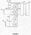
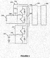
- Figures 4 and 5 show a circuit schematic for a specific example of the multi-source energy storage system 200 shown in Figure 3 .
- Figure 4 shows the status in precharge mode and
- Figure 5 shows the status in normal mode.
- the first switch device 214 is disconnected and the second and third switch devices 224 and 234 are closed.
- the first energy storage system 210 supplies power to the electrical load 260 via the first DC/DC converter 212, while simultaneously charging the second energy storage system 220 via the second DC/DC converter 222.
- the first and second switch devices 214 and 224 are closed and the third switch device 234 is disconnected.
- the first and second energy storage systems 210 and 220 couple to the electrical load 260 and supply power to the first and second DC/DC converters 212 and 222 respectively.
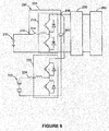
- the multi-source energy storage system 200 can operate in a further fail-safe mode.
- the fail-safe mode can be started, discontinuing use of the second energy storage system 220, the first DC/DC converter 212 and the second DC/DC converter 222, using only the first energy storage system 210 to directly supply power to the electrical load 260.
- the first and second switch devices 214 and 224 are disconnected and the third switch device 234 is closed.
- the first energy storage system 210 is used to supply power to the electrical load 260 via the bypass 230 and the second energy storage system 220 is decoupled from the electrical load 260.
- FIG. 7 shows the schematic block diagram for a specific example of the multi-source energy storage system 200 controller 250.
- the controller 250 can include a regulator 251, used to receive a reference current I ref and a sample current I fb obtained from an input current sample from the second DC/DC converter 222 and regulate the input of the second DC/DC converter 222 based on the reference current I ref .
- the input current of the second DC/DC converter 222 can be adjusted to the reference current I ref .
- the controller 250 can also include the regulators 252 and 253.
- Regulator 252 is used to regulate the bus voltage V bus of the first energy storage system 210 based on the reference voltage V bus _ ref , producing a reference voltage V i_ref .
- Regulator 253 is used to regulate the voltage V i_fb across the two terminals of the second energy storage system 220 based on the reference voltage V i_ref .
- the controller 250 in addition to regulators 251, 252 and 253, the controller 250 also includes a mode selection unit 255 and a comparator 257.
- the mode selection unit 255 selects the data from either regulator 251 or 253 depending on the mode in which the multi-source energy storage system 200 is operating (precharge mode or normal mode), in order to obtain the necessary voltage V comp .
- the comparator 257 compares this voltage V comp with the reference sawtooth wave voltageV ramp provided by the PWM controller, in order to perform PWN control.
- the regulator 251 regulates the input current of the second DC/DC converter 222 based on the relevant output voltage of the output load from the second DC/DC converter 222 and the mode selection unit 255 obtains a suitable voltage V comp based on the data generated by the regulator 251, used to perform PWM control.
- the regulator 252 regulates the bus voltage V bus of the first energy storage system 210 based on a reference voltage V bus _ ref , producing a reference voltage V i _ ref .
- Regulator 253 regulates the voltage V i_fb across the two terminals of the second energy storage system 220 based on this reference voltage V i_ref .
- the mode selection unit 255 obtains a suitable voltage V comp based on data produced by regulator 253, which is used to perform PWM control.
- the multi-source energy storage system can further include a third energy storage system that can be selectively coupled to the electrical load via a third DC/DC converter.
- the third energy storage system can be a fuel cell, a photovoltaic inverter, a generator or a combination of all these three.
- Another aspect of this invention is the energy management and control method for supplying power to an electrical load from multiple energy storage systems.
- this method includes the following steps:
- step S1 also includes: using the first energy storage to supply power to the electrical load via a bypass parallel to the first DC/DC converter.
- the bypass is connected to a first node located between the first energy storage system and the first DC/DC converter and a second node located between the first and second DC/DC converters and the electrical load. The resistance of the bypass is negligible compared to the first or second DC/DC converters.
- the bypass can also include a switch device.
- step S2 also includes: using the first energy storage to supply power to the electrical load via the first DC/DC converter.
- the multi-source energy storage system further includes a first switch device located between the first energy storage system and the first DC/DC converter, a second switch device located between the second energy storage system and the second DC/DC converter and a third switch device located in the bypass.
- step S1 the first switch device is disconnected and the second and third switch devices are closed and in step S2, the first and second switch devices are closed and the third switch device is disconnected.
- step S1 further includes: regulating the input current of the second DC/DC converter based on the output load of the second DC/DC converter.
- step S2 includes: regulating the bus voltage of the first energy storage system, so that it basically remains constant when in normal mode.
- the energy management and control method further includes: when either the second energy storage system, the first DC/DC converter or the second DC/DC converter malfunction, the first energy storage system supplies power to the electrical load via the bypass and the second energy storage system and electrical load are decoupled.
- This energy management and control system can use the previously mentioned methods or any of the multi-source energy storage systems from the examples. Specific features will not be repeated here.
- the multi-source energy storage system and energy management control method in the examples of this invention allow the high energy density energy storage system to precharge the high power density energy storage system when operating under normal conditions. The operator does not need to wait until the power density energy storage system is precharged before starting the system. In addition, the charging circuit does not require additional resistance in the precharge mode, which saves system power and increases the system's power density.
Landscapes
- Engineering & Computer Science (AREA)
- Power Engineering (AREA)
- Transportation (AREA)
- Mechanical Engineering (AREA)
- Life Sciences & Earth Sciences (AREA)
- Sustainable Development (AREA)
- Sustainable Energy (AREA)
- Charge And Discharge Circuits For Batteries Or The Like (AREA)
- Electric Propulsion And Braking For Vehicles (AREA)
Abstract
Description
- This invention is an energy storage system and method for energy management and control, primarily for use in electrical systems such as vehicle drive systems, specifically a multi-source energy storage system and method for energy management and control.
- As problems with pollution have become more serious, electric vehicles and renewable energy sources have become increasingly attractive. Pure electric vehicles are driven by power supplied to the electric motor using stored electrical energy. Pure electric vehicles can use one or more stored electrical energy sources. For example, a first electrical energy storage source, such as battery energy, can be used to provide longer lasting energy, and a second electrical energy storage source, such as a power battery, can be used to supply high powered energy, for use in accelerating, etc. Hybrid electrical vehicles are driven by a combination of an internal-combustion engine and an electric motor powered by an energy storage device (such as a traction battery). This combination runs by ensuring that the internal-combustion engine and the electric motor both operate at their highest efficiencies, increasing the overall fuel efficiency. For example, the efficiency of the electric motor is higher when accelerating from standstill and the efficiency of the internal-combustion engine is higher when the engine is running constantly over a period of time (for example, when driving on highways). Enhancing the initial acceleration of the electric motor allows the internal-combustion engine in hybrid vehicles to be smaller and more fuel-efficient.
- If the size of high energy density batteries in pure battery-powered electric vehicles and plug-in hybrid vehicles are reasonable, then a single charge is sufficient to meet mileage requirements. However, due to their relatively low power densities, high energy density batteries of the same size might be unable to satisfy power requirements caused by instant acceleration or uphill driving. This is especially apparent in heavy-duty applications, such as city buses or trucks. In view of this, multiple energy sources or hybrid energy sources can be used to simultaneously satisfy mileage requirements and power requirements, without having to excessively increase the size of single high energy density batteries. As power batteries have a higher power density and longer service life, they can be used in combination with high energy density batteries as a hybrid power source in heavy-duty electric vehicles. However, when introducing multiple energy sources or hybrid energy sources into a vehicle's drive system, the allocation and control of these multiple or hybrid energy sources become complicated. The question of how to reasonably allocate and control multiple energy sources or hybrid energy sources to improve the efficient operation of a vehicle's drive systems and cope with a variety of working conditions still needs to be resolved within the industry.
- Therefore, a system and method are required to resolve at least one of the problems above.
- One aspect of this invention is the provision of a multi-source energy storage system, which includes a first energy storage system, a second energy storage system, and a second DC/DC converter and controller. Of which the first energy storage system can be coupled to an electrical load. The second DC/DC converter can be coupled between at least one of the following: the second energy storage system and the first energy storage system or electrical load. The controller settings control the first and second energy storage systems and the second DC/DC converter runs in both the precharge mode and normal mode. In the precharge mode, the first energy storage system charges the second energy storage system via the second DC/DC converter. In the normal mode, the second energy storage couples to the electrical load via the second DC/DC converter.
- Another aspect of the present invention is to provide a method, includes:
- A multi-source energy storage system, whose operation includes a first energy storage system, a second energy storage system and a second DC/DC converter. In using the precharge mode, the first energy storage system charges the second energy storage system via the second DC/DC converter; and
- When operating the multi-source energy storage system in normal mode, the second energy storage supplies power to the electrical load via the second DC/DC converter.
- The multi-source energy storage system and energy management control method in this invention are not only able to supply energy to electrical loads such as vehicle drive systems by means of multiple different storage systems to satisfy the various power requirements of the electrical load, enabling it to operate in different working conditions, but are also able to transfer energy between the different energy storage systems without affecting the normal operation of the system. For example, when the system is operating normally, the high energy density energy storage system (such as batteries) can precharge the high power density energy storage system (such as a super capacitor). The operator does not need to wait until the power density energy storage system has been precharged before starting the system. In addition, high efficiency precharging is possible without additional resistance, saving system power and increasing the system's power density.
- A clearer understanding of these and the other characteristics, aspects and advantages of this invention can be obtained by referring to the attached figures when reading the following detailed explanation of various examples.
- In the attached figures, the same element reference numbers are used to denote the same parts in all figures.
-
Figure 1 is a schematic block diagram of a possible multi-source energy storage system which embodies the method in this invention. -
Figure 2 is a circuit schematic for a specific example of the multi-source energy storage system shown inFigure 1 . -
Figure 3 is another schematic block diagram of one possible multi-source energy storage system which embodies the method in this invention. -
Figures 4-6 are circuit schematics for specific examples of the multi-source energy storage system shown inFigure 3 .Figure 4 shows the status of this multi-source energy storage system in the precharge mode.Figure 5 shows the status of this multi-source energy storage system in normal mode.Figure 6 shows the status of this multi-source energy storage system in the fail-safe mode. -
Figure 7 shows the schematic block diagram for a specific example of the multi-source energy storage system controller shown inFigure 3 . -
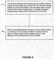
Figure 8 shows the flow chart for the method of supplying power to an electrical load using the multi-source energy storage system as described above. - In order to help technicians in this field clearly understand this invention, the following combines figures with a detailed description of the specific implementation of this invention. In the following detailed descriptions of specific implementation methods, this specification does not describe some commonly known functions or configurations in order to avoid unnecessary details affecting the this invention's disclosure.
- Unless otherwise defined, the technical or scientific terms used in this claim and specification will retain the ordinary meaning as understood by a layperson in the technical field of the present invention. "First", "second" and other similar words used in the present specification and the claim do not denote any order, quantity, or importance, but are simply used to distinguish different components. "A" or "a" and similar words do not mean a single unit, but indicate the presence of at least one unit. "Comprises" or "possesses" and other similar words imply that an element or object appearing before the "comprises" or "possesses" covers enumerated elements or objects and equivalents elements thereof appearing after the "comprises" or "possesses", without excluding other elements or objects. "Connected" or "coupled" and other similar words are not limited to physical or mechanical connections, but may include electrical connections, either in a direct or indirect manner.
- One aspect of the examples of this invention involves a multi-source energy storage system that can be used to supply electrical power to an electrical load in the fields of electrical vehicles, smart networks, micro-networks, solar energy and wind power.
-
Figure 1 shows a schematic block diagram of one possible multi-source energy storage system embodying the method in this invention. As shown inFigure 1 , the multi-sourceenergy storage system 100 includes a firstenergy storage system 110 that can be selectively coupled to theelectrical load 160, and a secondenergy storage system 120 that can be coupled to theelectrical load 160 via a DC/DC converter 122. Of which, one terminal of the DC/DC converter 122 is coupled to the secondenergy storage system 120 and the other terminal is coupled to the firstenergy storage system 110 and theelectrical load 160. - The multi-source
energy storage system 100 also includes acontroller 150, used to control the operation of the first and second energy storage systems, 100 and 120, and theconverter 122 in different modes. For example, in some examples, the multi-sourceenergy storage system 100 can be run in at least one precharge mode and one normal mode under the control of thecontroller 150. In the precharge mode, the firstenergy storage system 110 charges the secondenergy storage system 120 via the DC/DC converter 122. In normal mode, the secondenergy storage system 120 couples to theelectrical load 160 via the DC/DC converter 160. In examples such as the one shown inFigure 1 , when in the precharge and normal mode, the firstenergy storage system 110 also couples with and supplies electrical power to theelectrical load 160. - A
switch device 114 can be fitted between the firstenergy storage system 110 and theelectrical load 160 to enable selective coupling between the two. Similarly, a switch device can also be fitted between the secondenergy storage system 120 and theelectrical load 160, or specifically, aswitch device 124 can be fitted between the secondenergy storage system 120 and the DC/DC converter 122 to enable selective coupling between the two. - The first energy storage system described here can be a high energy density storage system, such as a high energy battery (lead-acid batteries, etc.), a generator, a fuel cell and a photovoltaic inverter, etc. The second energy storage system can be a high power storage system, such as a super capacitor, etc. The switch device can be any kind of switch or a combination of switch elements. The DC/DC converter refers to a voltage converter used to convert fixed DC voltage into variable DC voltage. The converter generally includes several major functional modules, such as a pulse width modulation (PWM) module, an error amplifier module and a comparator module.
-
Figure 2 shows a circuit schematic for the specific example of the multi-sourceenergy storage system 100 shown inFigure 1 . As shown inFigure 2 , the lead-acid battery 110 is used as the first energy storage system which can selectively couple to theelectrical load 160 by means of theswitch device 114. Thesuper capacitor 120 is used as the second energy storage system which can selectively couple to the DC/DC converter 122 by means of theswitch device 124, and couple to either theelectrical load 160 or the lead-acid battery 110 via the DC/DC converter 122. Therefore, in the precharge mode, the lead-acid battery 110 can be controlled by thecontroller 150 so as to charge thesuper capacitor 120 via the DC/DC converter 122. In normal mode, thesuper capacitor 120 can be used to supply power to theelectrical load 160 via the DC/DC converter 122. In addition, the multi-sourceenergy storage system 100 also includes acapacitor 140 connected in parallel with the firstenergy storage system 110 and the secondenergy storage system 120, and is used to stabilize the output voltage of themulti-source storage system 100. -
Figure 3 shows a schematic block diagram of another possible multi-source energy storage system embodying the method in this invention. As shown inFigure 3 , the multi-sourceenergy storage system 200 includes a firstenergy storage system 210 and a secondenergy storage system 220 that can be coupled to theelectrical load 260 via the first DC/DC converter 212 and second DC/DC converter 222 respectively. The first and second DC/DC converters DC converter 212 is coupled to the firstenergy storage system 210, and the other terminal is coupled to the second DC/DC converter 222 and theelectrical load 260 via the node between the second DC/DC converter 222 and theelectrical load 260. One terminal of the second DC/DC converter 222 is coupled to thesecond storage system 220, and the other terminal is coupled to the first DC/DC converter 212 and theelectrical load 260 via the node between the first DC/DC converter 212 and theelectrical load 260. Thefirst switch device 214 is connected between the firstenergy storage system 210 and the first DC/DC converter 212 and thesecond switch device 224 is connected between the secondenergy storage system 220 and the second DC/DC converter 222. - The multi-source
energy storage system 200 also includes abypass 230 in parallel with the DC/DC converter 212. Via this bypass, the firstenergy storage system 210 can couple to the node between the second DC/DC converter 222 andelectrical load 260 without passing through the first DC/DC converter 212. Thus, the firstenergy storage system 210 can be coupled to the second energy storage system via the second DC/DC converter, or directly to theelectrical load 260. In the specific example shown inFigure 3 , thebypass 230 connects to thefirst node 236 located between the firstenergy storage system 210 and the first DC/DC converter 212, and thesecond node 236, located between the first and second DC/DC converters electrical load 260. Thebypass 230 can also include a switch device (the third switch device) 234. Compared to theconverters bypass 230 is negligible. In a specific example, thebypass 230 only includes theswitch device 234 and does not include other elements with greater resistance. Thus, when using the firstenergy storage system 210 to precharge the secondenergy storage system 220 via thebypass 230, energy loss can be reduced to a minimum. - The multi-source
energy storage system 200 also includes acontroller 250, used to control the operation of the first and secondenergy storage systems converters bypass 230 in at least one precharge mode and one normal mode. In precharge mode, the firstenergy storage system 210 charges the secondenergy storage system 220 via the DC/DC converter 222. In normal mode, the secondenergy storage system 220 couples to theelectrical load 260 via the DC/DC converter 222. -
Figures 4 and5 show a circuit schematic for a specific example of the multi-sourceenergy storage system 200 shown inFigure 3 .Figure 4 shows the status in precharge mode andFigure 5 shows the status in normal mode. - In the precharge mode, as shown in
Figure 4 , thefirst switch device 214 is disconnected and the second andthird switch devices energy storage system 210 supplies power to theelectrical load 260 via the first DC/DC converter 212, while simultaneously charging the secondenergy storage system 220 via the second DC/DC converter 222. In normal mode, as shown inFigure 5 , the first andsecond switch devices third switch device 234 is disconnected. The first and secondenergy storage systems electrical load 260 and supply power to the first and second DC/DC converters - In addition, in some examples, under the control of the
controller 250, the multi-sourceenergy storage system 200 can operate in a further fail-safe mode. In the event that either the secondenergy storage system 220, the first DC/DC converter 212 or the second DC/DC converter 222 malfunctions, the fail-safe mode can be started, discontinuing use of the secondenergy storage system 220, the first DC/DC converter 212 and the second DC/DC converter 222, using only the firstenergy storage system 210 to directly supply power to theelectrical load 260. As shown inFigure 6 , in the fail-safe mode, the first andsecond switch devices third switch device 234 is closed. The firstenergy storage system 210 is used to supply power to theelectrical load 260 via thebypass 230 and the secondenergy storage system 220 is decoupled from theelectrical load 260. -
Figure 7 shows the schematic block diagram for a specific example of the multi-sourceenergy storage system 200controller 250. As shown inFigure 7 , thecontroller 250 can include aregulator 251, used to receive a reference current Iref and a sample current Ifb obtained from an input current sample from the second DC/DC converter 222 and regulate the input of the second DC/DC converter 222 based on the reference current Iref. For example, the input current of the second DC/DC converter 222 can be adjusted to the reference current Iref. Thecontroller 250 can also include theregulators Regulator 252 is used to regulate the bus voltage Vbus of the firstenergy storage system 210 based on the reference voltage Vbus_ref, producing a reference voltage Vi_ref. Regulator 253 is used to regulate the voltage Vi_fb across the two terminals of the secondenergy storage system 220 based on the reference voltage Vi_ref. - In the specific example shown in
Figure 7 , in addition toregulators controller 250 also includes amode selection unit 255 and acomparator 257. Themode selection unit 255 selects the data from eitherregulator energy storage system 200 is operating (precharge mode or normal mode), in order to obtain the necessary voltage Vcomp. Thecomparator 257 compares this voltage Vcomp with the reference sawtooth wave voltageVramp provided by the PWM controller, in order to perform PWN control. - Specifically, in the precharging mode, the
regulator 251 regulates the input current of the second DC/DC converter 222 based on the relevant output voltage of the output load from the second DC/DC converter 222 and themode selection unit 255 obtains a suitable voltage Vcomp based on the data generated by theregulator 251, used to perform PWM control. In normal mode, theregulator 252 regulates the bus voltage Vbus of the firstenergy storage system 210 based on a reference voltage Vbus_ref, producing a reference voltage Vi_ref.Regulator 253 regulates the voltage Vi_fb across the two terminals of the secondenergy storage system 220 based on this reference voltage Vi_ref. Themode selection unit 255 obtains a suitable voltage Vcomp based on data produced byregulator 253, which is used to perform PWM control. - In all the example multi-source energy storage systems, one or more extra energy storage systems can be used in parallel with the first and second energy storage systems. For example, in some examples, the multi-source energy storage system can further include a third energy storage system that can be selectively coupled to the electrical load via a third DC/DC converter. The third energy storage system can be a fuel cell, a photovoltaic inverter, a generator or a combination of all these three.
- Another aspect of this invention is the energy management and control method for supplying power to an electrical load from multiple energy storage systems. In a specific example, as shown in
Figure 8 , this method includes the following steps: - In step S1, the multi-source energy storage system, includes a first energy storage system, a second energy storage system and a second DC/DC converter, put into the precharge mode. In this step, the first energy storage system charges the second energy storage system via the second DC/DC converter.
- In step S2, the multi-source energy storage system is put into normal mode. In this step, the second energy storage supplies power to the electrical load via the second DC/DC converter.
- In some examples, step S1 also includes: using the first energy storage to supply power to the electrical load via a bypass parallel to the first DC/DC converter. In some of these examples, the bypass is connected to a first node located between the first energy storage system and the first DC/DC converter and a second node located between the first and second DC/DC converters and the electrical load. The resistance of the bypass is negligible compared to the first or second DC/DC converters. The bypass can also include a switch device.
- In some examples, step S2 also includes: using the first energy storage to supply power to the electrical load via the first DC/DC converter.
- In some examples, the multi-source energy storage system further includes a first switch device located between the first energy storage system and the first DC/DC converter, a second switch device located between the second energy storage system and the second DC/DC converter and a third switch device located in the bypass. In step S1, the first switch device is disconnected and the second and third switch devices are closed and in step S2, the first and second switch devices are closed and the third switch device is disconnected.
- In some examples, step S1 further includes: regulating the input current of the second DC/DC converter based on the output load of the second DC/DC converter.
- In some examples, step S2 includes: regulating the bus voltage of the first energy storage system, so that it basically remains constant when in normal mode.
- In some examples, the energy management and control method further includes: when either the second energy storage system, the first DC/DC converter or the second DC/DC converter malfunction, the first energy storage system supplies power to the electrical load via the bypass and the second energy storage system and electrical load are decoupled.
- This energy management and control system can use the previously mentioned methods or any of the multi-source energy storage systems from the examples. Specific features will not be repeated here.
- The multi-source energy storage system and energy management control method in the examples of this invention allow the high energy density energy storage system to precharge the high power density energy storage system when operating under normal conditions. The operator does not need to wait until the power density energy storage system is precharged before starting the system. In addition, the charging circuit does not require additional resistance in the precharge mode, which saves system power and increases the system's power density.
- Although the present invention is described with reference to specific implementation methods, technicians in the field should understand that many modifications and variations may be made for the present invention. Therefore, they should be aware that, intention of the claim lies in all the modifications and variations covered in the real concept and scope of the present invention.
Claims (12)
- A multi-source energy storage system (100), which includes:a first energy storage system (110), which can be coupled to an electrical load;a second energy storage system (120);a second DC/DC converter (122), which can be coupled to either the second energy storage system (120), first energy storage system (110) or an electrical load; anda controller (150), the settings of which, control the first and second energy storage systems and the second DC/DC converter running in both precharge mode and normal mode, of which:in precharge mode, the first energy storage system (110) charges the second energy storage system (120) via the second DC/DC converter; andin normal mode, the second energy storage couples to the electrical load via the second DC/DC converter (122).
- A multi-source energy storage system according to Claim 1, which further includes:a first DC/DC converter, which can be coupled between the first energy storage system and the electrical load; anda bypass, which can be coupled between at least one of the following: the first energy storage system and the first DC/DC converter input terminal, the second DC/DC converter input terminal and/or the electrical load input terminal, of which:when in precharge mode, the first energy storage system is coupled to the second DC/DC converter and electrical load via the aforementioned bypass.when in normal mode, the first and second energy storage systems are coupled to the electrical load via the first and second DC/DC converters respectively.
- A method, which includes:a multi-source energy storage system, those operation of which includes a first energy storage system, a second energy storage system and a second DC/DC converter, wherein when used in the precharge mode, the first energy storage system charges the second energy storage system via the second DC/DC converter; andwhen the aforementioned multi-source energy storage system is used in normal mode, includes using the second energy storage to supply power to the electrical load via the second DC/DC converter.
- The method according to Claim 3, further including: when in the precharge mode, the input current of the second DC/DC converter is adjusted on the basis of the second DC/DC converter output load.
- The method according to Claim 3 or Claim 4, further includes: a bus voltage to adjust the first energy storage system, enabling it to remain constant in normal mode.
- The method according to any of Claims 3 to 5, wherein when the multi-source energy storage system is in normal mode, further includes: using the aforementioned first energy storage to supply power to the electrical load via the first DC/DC converter.
- The method according to any of Claims 3 to 6, wherein when the multi-source energy storage system is in precharge mode, further includes: the aforementioned first energy storage supplies power to the electrical load via a bypass parallel to the first DC/DC converter.
- The method according to any of Claims 3 to 7, of which further includes: when either the second energy storage system, the first DC/DC converter or the second DC/DC converter malfunctions, the first energy storage system supplies power to the electrical load via the bypass and the second energy storage system and electrical load are decoupled.
- The multi-source energy storage system as described in Claim 2 or the method described in Claim 7, of which the bypass connects to the first node located between the first energy storage system and the first DC/DC converter and the second node located between the first and second DC/DC converters and the electrical load.
- The multi-source energy storage system as described in Claim 2 or the method as described in Claim 7, of which the bypass includes a switch device.
- The multi-source energy storage system as described in Claim 1 or the method as described in Claim 3, of which the multi-source energy storage system further includes:a first switch device, located between the first energy storage system and the first DC/DC converter;a second switch device, located between the second energy storage system and the second DC/DC converter; anda third switch device, located in the bypass, of which when in precharge mode, the first switch device is disconnected and the second and third switch devices are closed. When in normal mode, the first and second switch devices are closed and the third switch device is disconnected.
- A multi-source energy storage system as described in Claim 1 or method as described in Claim 3, in which the first energy storage system further includes either a battery or a generator and the second energy storage system includes a super capacitor.
Applications Claiming Priority (1)
| Application Number | Priority Date | Filing Date | Title |
|---|---|---|---|
| CN201510148732.XA CN106143171A (en) | 2015-03-31 | 2015-03-31 | Multi-source energy storage system and energy management control method |
Publications (3)
| Publication Number | Publication Date |
|---|---|
| EP3075595A2 true EP3075595A2 (en) | 2016-10-05 |
| EP3075595A3 EP3075595A3 (en) | 2016-10-12 |
| EP3075595B1 EP3075595B1 (en) | 2023-10-25 |
Family
ID=55696973
Family Applications (1)
| Application Number | Title | Priority Date | Filing Date |
|---|---|---|---|
| EP16162905.0A Active EP3075595B1 (en) | 2015-03-31 | 2016-03-30 | A multi-source energy storage system and method for energy management and control |
Country Status (8)
| Country | Link |
|---|---|
| US (1) | US10056755B2 (en) |
| EP (1) | EP3075595B1 (en) |
| JP (1) | JP6742771B2 (en) |
| KR (1) | KR102493179B1 (en) |
| CN (1) | CN106143171A (en) |
| BR (1) | BR102016007005B1 (en) |
| CA (1) | CA2924167C (en) |
| MX (1) | MX361187B (en) |
Families Citing this family (19)
| Publication number | Priority date | Publication date | Assignee | Title |
|---|---|---|---|---|
| WO2015001621A1 (en) * | 2013-07-02 | 2015-01-08 | 三菱電機株式会社 | Hybrid drive system |
| CN106143170B (en) * | 2015-03-31 | 2020-11-17 | 通用电气公司 | Energy storage system with range extender and energy management control method |
| JP6524883B2 (en) * | 2015-10-19 | 2019-06-05 | 住友電気工業株式会社 | Power converter and control method thereof |
| US10060269B2 (en) | 2015-12-21 | 2018-08-28 | General Electric Company | Cooling circuits for a multi-wall blade |
| CN107294145A (en) * | 2016-03-30 | 2017-10-24 | 通用电气公司 | charging device, system and method |
| DE102016225107A1 (en) * | 2016-12-15 | 2018-06-21 | Bayerische Motoren Werke Aktiengesellschaft | ELEKTROMASCHINEN ARRANGEMENT |
| US11404875B2 (en) | 2017-02-08 | 2022-08-02 | Battelle Energy Alliance, Llc | Energy management system, method of controlling one or more energy storage devices and control unit for one or more power storage units |
| JOP20190226A1 (en) * | 2017-04-04 | 2019-09-29 | Calvin Cuong Cao | Highly efficient system for generating and charging electrical energy |
| CN108808754B (en) | 2017-05-03 | 2020-10-16 | 华为技术有限公司 | Distributed battery, battery control method and electric vehicle |
| US10778024B2 (en) * | 2018-04-20 | 2020-09-15 | Wing Aviation Llc | Hybrid energy storage system with multiple energy and power densities |
| US11063460B2 (en) | 2018-06-01 | 2021-07-13 | Samsung Sdi Co., Ltd. | Battery system |
| CN110676833B (en) * | 2018-07-02 | 2021-12-07 | 比亚迪股份有限公司 | Track energy feedback system and control method thereof |
| DE102018116148A1 (en) * | 2018-07-04 | 2020-01-09 | Dr. Ing. H.C. F. Porsche Aktiengesellschaft | aircraft |
| CN114391205A (en) * | 2019-09-27 | 2022-04-22 | 株式会社自动网络技术研究所 | Power supply system |
| CN112865272A (en) * | 2019-11-27 | 2021-05-28 | 株洲中车时代电气股份有限公司 | Power generation system and power generation method for multi-source railway wagon |
| CN111682615A (en) * | 2020-06-18 | 2020-09-18 | 格力博(江苏)股份有限公司 | Charging control circuit, charging device and charging system |
| WO2023272630A1 (en) * | 2021-06-30 | 2023-01-05 | 合肥乘翎微电子有限公司 | Multiphase series-capacitor dc-dc converter and control method |
| JP7890043B2 (en) * | 2022-03-17 | 2026-07-14 | 株式会社小松製作所 | Work vehicles |
| US12542439B2 (en) | 2022-09-13 | 2026-02-03 | Council Of Scientific And Industrial Research | Switched reconfigurable multi-converter multi-source energy storage system configuration for electrified vehicles and power flow control scheme thereof |
Family Cites Families (34)
| Publication number | Priority date | Publication date | Assignee | Title |
|---|---|---|---|---|
| US5318142A (en) | 1992-11-05 | 1994-06-07 | Ford Motor Company | Hybrid drive system |
| US5264764A (en) | 1992-12-21 | 1993-11-23 | Ford Motor Company | Method for controlling the operation of a range extender for a hybrid electric vehicle |
| US20020163198A1 (en) | 2001-05-03 | 2002-11-07 | Gee Thomas Scott | Fail-safe engine cooling control algorithm for hybrid electric vehicle |
| US7109686B2 (en) | 2004-11-15 | 2006-09-19 | Ise Corporation | System and method for precharging and discharging a high power ultracapacitor pack |
| US7568537B2 (en) * | 2006-01-09 | 2009-08-04 | General Electric Company | Vehicle propulsion system |
| US7595597B2 (en) | 2006-01-18 | 2009-09-29 | General Electric Comapany | Vehicle propulsion system |
| JP4288333B1 (en) | 2007-12-18 | 2009-07-01 | トヨタ自動車株式会社 | Vehicle power supply |
| KR100921125B1 (en) | 2008-03-04 | 2009-10-12 | 현대자동차주식회사 | Hybrid Fuel Cell Vehicle with Multi-Power Source and Multi-Drive System |
| US8120290B2 (en) | 2008-10-13 | 2012-02-21 | General Electric Company | Energy management system to improve efficiency of electric and hybrid drive trains |
| KR101487560B1 (en) * | 2008-12-24 | 2015-01-29 | 두산인프라코어 주식회사 | Industrial vehicle power supply and control method thereof |
| KR101519666B1 (en) * | 2009-09-11 | 2015-05-12 | 현대자동차주식회사 | Control method for fuel cell hybrid vehicle |
| DE102009029417A1 (en) | 2009-09-14 | 2011-03-24 | Robert Bosch Gmbh | Method and device for operating a hybrid vehicle in the event of a malfunction of an energy system |
| KR101088414B1 (en) * | 2009-11-03 | 2011-12-01 | 한국철도기술연구원 | Hybrid propulsion system and driving method with multiple contacts |
| US8245801B2 (en) | 2009-11-05 | 2012-08-21 | Bluways Usa, Inc. | Expandable energy storage control system architecture |
| US20110100735A1 (en) | 2009-11-05 | 2011-05-05 | Ise Corporation | Propulsion Energy Storage Control System and Method of Control |
| KR101039679B1 (en) | 2009-11-17 | 2011-06-09 | 현대자동차주식회사 | Mild hybrid system and method controlling thereof |
| JP4712895B2 (en) * | 2010-01-13 | 2011-06-29 | 本田技研工業株式会社 | Fuel cell vehicle |
| CN102822001A (en) * | 2010-01-25 | 2012-12-12 | 麦斯韦尔技术股份有限公司 | Energy storage systems and methods |
| JP5189607B2 (en) * | 2010-02-04 | 2013-04-24 | トヨタ自動車株式会社 | Vehicle power supply |
| DE102010008917A1 (en) * | 2010-02-23 | 2011-08-25 | Liebherr-Werk Biberach GmbH, 88400 | Drive system and work machine |
| JP2012034515A (en) | 2010-07-30 | 2012-02-16 | Sanyo Electric Co Ltd | Power supply device for vehicle |
| US8378623B2 (en) | 2010-11-05 | 2013-02-19 | General Electric Company | Apparatus and method for charging an electric vehicle |
| CN102005810A (en) * | 2010-11-26 | 2011-04-06 | 刘卉 | Vehicle power supply system and method, power supply, installation device and power conversion device |
| WO2012138991A2 (en) | 2011-04-08 | 2012-10-11 | Polaris Industries Inc. | Electric vehicle with range extender |
| US9073438B2 (en) * | 2011-10-28 | 2015-07-07 | General Electric Company | System for selectively coupling an energy source to a load and method of making same |
| JP5995041B2 (en) * | 2011-11-30 | 2016-09-21 | オムロン株式会社 | Charge control device, solar power generation system, and charge control method |
| US9804622B2 (en) | 2012-01-05 | 2017-10-31 | Schneider Electric It Corporation | Calibration of current sensors in parallel power converters |
| US8981727B2 (en) * | 2012-05-21 | 2015-03-17 | General Electric Company | Method and apparatus for charging multiple energy storage devices |
| CN102700432B (en) | 2012-05-23 | 2014-09-03 | 重庆小康工业集团股份有限公司 | Distance increase device of electric vehicle |
| PL2931551T3 (en) | 2012-12-12 | 2021-12-06 | Tevva Motors Limited | Range extender control |
| US9174525B2 (en) | 2013-02-25 | 2015-11-03 | Fairfield Manufacturing Company, Inc. | Hybrid electric vehicle |
| US8818601B1 (en) | 2013-03-14 | 2014-08-26 | GM Global Technology Operations LLC | Extended-range electric vehicle with supercapacitor range extender |
| WO2014209377A1 (en) | 2013-06-28 | 2014-12-31 | Schneider Electric It Corporation | Uninterruptible power supply control |
| JP6183699B2 (en) * | 2013-08-07 | 2017-08-23 | スズキ株式会社 | Fuel cell vehicle |
-
2015
- 2015-03-31 CN CN201510148732.XA patent/CN106143171A/en active Pending
-
2016
- 2016-03-17 CA CA2924167A patent/CA2924167C/en active Active
- 2016-03-22 JP JP2016056436A patent/JP6742771B2/en not_active Expired - Fee Related
- 2016-03-29 KR KR1020160037805A patent/KR102493179B1/en active Active
- 2016-03-30 EP EP16162905.0A patent/EP3075595B1/en active Active
- 2016-03-30 MX MX2016004109A patent/MX361187B/en active IP Right Grant
- 2016-03-30 BR BR102016007005-8A patent/BR102016007005B1/en not_active IP Right Cessation
- 2016-03-31 US US15/086,744 patent/US10056755B2/en active Active
Non-Patent Citations (1)
| Title |
|---|
| None |
Also Published As
| Publication number | Publication date |
|---|---|
| BR102016007005B1 (en) | 2022-08-16 |
| CN106143171A (en) | 2016-11-23 |
| CA2924167C (en) | 2024-01-09 |
| CA2924167A1 (en) | 2016-09-30 |
| MX2016004109A (en) | 2016-09-29 |
| JP2016195530A (en) | 2016-11-17 |
| US20160294182A1 (en) | 2016-10-06 |
| KR20160117310A (en) | 2016-10-10 |
| KR102493179B1 (en) | 2023-01-27 |
| EP3075595A3 (en) | 2016-10-12 |
| EP3075595B1 (en) | 2023-10-25 |
| BR102016007005A2 (en) | 2016-10-25 |
| US10056755B2 (en) | 2018-08-21 |
| MX361187B (en) | 2018-11-29 |
| JP6742771B2 (en) | 2020-08-19 |
Similar Documents
| Publication | Publication Date | Title |
|---|---|---|
| CA2924167C (en) | Multi-source energy storage system and energy management and control method | |
| US10358041B2 (en) | Electric vehicle | |
| JP3655277B2 (en) | Electric motor power management system | |
| EP2193954B1 (en) | Auxiliary drive apparatus and method of manufacturing same | |
| CA2925245C (en) | Energy storage system with range extender and energy management and control method | |
| JP6012915B1 (en) | Power converter | |
| US9013168B2 (en) | System for transferring energy from an energy source and method of making same | |
| JP5079709B2 (en) | Vehicle propulsion system | |
| CN109038700B (en) | Power conversion device, control method thereof, and vehicle including same | |
| CN201388079Y (en) | Hybrid electric vehicle charger | |
| CN1819419A (en) | Double-ended inverter drive system topology for a hybrid vehicle | |
| KR20090104171A (en) | How to charge the battery of an electric vehicle | |
| CN109204066B (en) | A fuel cell power system and its control method, vehicle controller, and automobile | |
| CN116394773A (en) | Vehicle control method, device, vehicle and computer readable storage medium | |
| JP7768078B2 (en) | Solar Charging System | |
| Pancholi et al. | Comparative analysis of hybrid electric vehicle FED through DC-DC converter and operated with battery and ultracapacitor | |
| CN117791802A (en) | Active energy type energy recovery battery balance management system and method | |
| JP2024044689A (en) | solar charging system | |
| KR20170047838A (en) | Integrated power unit for 48v-12v | |
| Tvarožek et al. | Optimalization of Buck-Boost converter for automotive | |
| JP2024022295A (en) | solar charging device | |
| CN118769917A (en) | A power battery system for HEV |
Legal Events
| Date | Code | Title | Description |
|---|---|---|---|
| PUAI | Public reference made under article 153(3) epc to a published international application that has entered the european phase |
Free format text: ORIGINAL CODE: 0009012 |
|
| PUAL | Search report despatched |
Free format text: ORIGINAL CODE: 0009013 |
|
| AK | Designated contracting states |
Kind code of ref document: A2 Designated state(s): AL AT BE BG CH CY CZ DE DK EE ES FI FR GB GR HR HU IE IS IT LI LT LU LV MC MK MT NL NO PL PT RO RS SE SI SK SM TR |
|
| AX | Request for extension of the european patent |
Extension state: BA ME |
|
| AK | Designated contracting states |
Kind code of ref document: A3 Designated state(s): AL AT BE BG CH CY CZ DE DK EE ES FI FR GB GR HR HU IE IS IT LI LT LU LV MC MK MT NL NO PL PT RO RS SE SI SK SM TR |
|
| AX | Request for extension of the european patent |
Extension state: BA ME |
|
| RIC1 | Information provided on ipc code assigned before grant |
Ipc: H02J 9/00 20060101ALI20160902BHEP Ipc: B60L 11/18 20060101AFI20160902BHEP |
|
| STAA | Information on the status of an ep patent application or granted ep patent |
Free format text: STATUS: REQUEST FOR EXAMINATION WAS MADE |
|
| 17P | Request for examination filed |
Effective date: 20170412 |
|
| RBV | Designated contracting states (corrected) |
Designated state(s): AL AT BE BG CH CY CZ DE DK EE ES FI FR GB GR HR HU IE IS IT LI LT LU LV MC MK MT NL NO PL PT RO RS SE SI SK SM TR |
|
| STAA | Information on the status of an ep patent application or granted ep patent |
Free format text: STATUS: EXAMINATION IS IN PROGRESS |
|
| 17Q | First examination report despatched |
Effective date: 20201110 |
|
| REG | Reference to a national code |
Ref country code: DE Ref legal event code: R079 Free format text: PREVIOUS MAIN CLASS: B60L0011180000 Ipc: B60L0058200000 Ref document number: 602016083623 Country of ref document: DE |
|
| RIC1 | Information provided on ipc code assigned before grant |
Ipc: H02J 3/28 20060101ALI20230209BHEP Ipc: B60L 58/20 20190101AFI20230209BHEP |
|
| GRAP | Despatch of communication of intention to grant a patent |
Free format text: ORIGINAL CODE: EPIDOSNIGR1 |
|
| STAA | Information on the status of an ep patent application or granted ep patent |
Free format text: STATUS: GRANT OF PATENT IS INTENDED |
|
| INTG | Intention to grant announced |
Effective date: 20230406 |
|
| GRAJ | Information related to disapproval of communication of intention to grant by the applicant or resumption of examination proceedings by the epo deleted |
Free format text: ORIGINAL CODE: EPIDOSDIGR1 |
|
| STAA | Information on the status of an ep patent application or granted ep patent |
Free format text: STATUS: EXAMINATION IS IN PROGRESS |
|
| GRAP | Despatch of communication of intention to grant a patent |
Free format text: ORIGINAL CODE: EPIDOSNIGR1 |
|
| STAA | Information on the status of an ep patent application or granted ep patent |
Free format text: STATUS: GRANT OF PATENT IS INTENDED |
|
| INTC | Intention to grant announced (deleted) | ||
| INTG | Intention to grant announced |
Effective date: 20230711 |
|
| GRAS | Grant fee paid |
Free format text: ORIGINAL CODE: EPIDOSNIGR3 |
|
| GRAA | (expected) grant |
Free format text: ORIGINAL CODE: 0009210 |
|
| STAA | Information on the status of an ep patent application or granted ep patent |
Free format text: STATUS: THE PATENT HAS BEEN GRANTED |
|
| AK | Designated contracting states |
Kind code of ref document: B1 Designated state(s): AL AT BE BG CH CY CZ DE DK EE ES FI FR GB GR HR HU IE IS IT LI LT LU LV MC MK MT NL NO PL PT RO RS SE SI SK SM TR |
|
| REG | Reference to a national code |
Ref country code: GB Ref legal event code: FG4D |
|
| REG | Reference to a national code |
Ref country code: CH Ref legal event code: EP |
|
| REG | Reference to a national code |
Ref country code: DE Ref legal event code: R096 Ref document number: 602016083623 Country of ref document: DE |
|
| REG | Reference to a national code |
Ref country code: IE Ref legal event code: FG4D |
|
| REG | Reference to a national code |
Ref country code: LT Ref legal event code: MG9D |
|
| REG | Reference to a national code |
Ref country code: NL Ref legal event code: MP Effective date: 20231025 |
|
| REG | Reference to a national code |
Ref country code: AT Ref legal event code: MK05 Ref document number: 1624350 Country of ref document: AT Kind code of ref document: T Effective date: 20231025 |
|
| PG25 | Lapsed in a contracting state [announced via postgrant information from national office to epo] |
Ref country code: NL Free format text: LAPSE BECAUSE OF FAILURE TO SUBMIT A TRANSLATION OF THE DESCRIPTION OR TO PAY THE FEE WITHIN THE PRESCRIBED TIME-LIMIT Effective date: 20231025 |
|
| PG25 | Lapsed in a contracting state [announced via postgrant information from national office to epo] |
Ref country code: GR Free format text: LAPSE BECAUSE OF FAILURE TO SUBMIT A TRANSLATION OF THE DESCRIPTION OR TO PAY THE FEE WITHIN THE PRESCRIBED TIME-LIMIT Effective date: 20240126 |
|
| PG25 | Lapsed in a contracting state [announced via postgrant information from national office to epo] |
Ref country code: IS Free format text: LAPSE BECAUSE OF FAILURE TO SUBMIT A TRANSLATION OF THE DESCRIPTION OR TO PAY THE FEE WITHIN THE PRESCRIBED TIME-LIMIT Effective date: 20240225 |
|
| PG25 | Lapsed in a contracting state [announced via postgrant information from national office to epo] |
Ref country code: LT Free format text: LAPSE BECAUSE OF FAILURE TO SUBMIT A TRANSLATION OF THE DESCRIPTION OR TO PAY THE FEE WITHIN THE PRESCRIBED TIME-LIMIT Effective date: 20231025 |
|
| PG25 | Lapsed in a contracting state [announced via postgrant information from national office to epo] |
Ref country code: AT Free format text: LAPSE BECAUSE OF FAILURE TO SUBMIT A TRANSLATION OF THE DESCRIPTION OR TO PAY THE FEE WITHIN THE PRESCRIBED TIME-LIMIT Effective date: 20231025 |
|
| PG25 | Lapsed in a contracting state [announced via postgrant information from national office to epo] |
Ref country code: ES Free format text: LAPSE BECAUSE OF FAILURE TO SUBMIT A TRANSLATION OF THE DESCRIPTION OR TO PAY THE FEE WITHIN THE PRESCRIBED TIME-LIMIT Effective date: 20231025 |
|
| PG25 | Lapsed in a contracting state [announced via postgrant information from national office to epo] |
Ref country code: LT Free format text: LAPSE BECAUSE OF FAILURE TO SUBMIT A TRANSLATION OF THE DESCRIPTION OR TO PAY THE FEE WITHIN THE PRESCRIBED TIME-LIMIT Effective date: 20231025 Ref country code: IS Free format text: LAPSE BECAUSE OF FAILURE TO SUBMIT A TRANSLATION OF THE DESCRIPTION OR TO PAY THE FEE WITHIN THE PRESCRIBED TIME-LIMIT Effective date: 20240225 Ref country code: GR Free format text: LAPSE BECAUSE OF FAILURE TO SUBMIT A TRANSLATION OF THE DESCRIPTION OR TO PAY THE FEE WITHIN THE PRESCRIBED TIME-LIMIT Effective date: 20240126 Ref country code: ES Free format text: LAPSE BECAUSE OF FAILURE TO SUBMIT A TRANSLATION OF THE DESCRIPTION OR TO PAY THE FEE WITHIN THE PRESCRIBED TIME-LIMIT Effective date: 20231025 Ref country code: BG Free format text: LAPSE BECAUSE OF FAILURE TO SUBMIT A TRANSLATION OF THE DESCRIPTION OR TO PAY THE FEE WITHIN THE PRESCRIBED TIME-LIMIT Effective date: 20240125 Ref country code: AT Free format text: LAPSE BECAUSE OF FAILURE TO SUBMIT A TRANSLATION OF THE DESCRIPTION OR TO PAY THE FEE WITHIN THE PRESCRIBED TIME-LIMIT Effective date: 20231025 Ref country code: PT Free format text: LAPSE BECAUSE OF FAILURE TO SUBMIT A TRANSLATION OF THE DESCRIPTION OR TO PAY THE FEE WITHIN THE PRESCRIBED TIME-LIMIT Effective date: 20240226 |
|
| PG25 | Lapsed in a contracting state [announced via postgrant information from national office to epo] |
Ref country code: SE Free format text: LAPSE BECAUSE OF FAILURE TO SUBMIT A TRANSLATION OF THE DESCRIPTION OR TO PAY THE FEE WITHIN THE PRESCRIBED TIME-LIMIT Effective date: 20231025 Ref country code: RS Free format text: LAPSE BECAUSE OF FAILURE TO SUBMIT A TRANSLATION OF THE DESCRIPTION OR TO PAY THE FEE WITHIN THE PRESCRIBED TIME-LIMIT Effective date: 20231025 Ref country code: PL Free format text: LAPSE BECAUSE OF FAILURE TO SUBMIT A TRANSLATION OF THE DESCRIPTION OR TO PAY THE FEE WITHIN THE PRESCRIBED TIME-LIMIT Effective date: 20231025 Ref country code: NO Free format text: LAPSE BECAUSE OF FAILURE TO SUBMIT A TRANSLATION OF THE DESCRIPTION OR TO PAY THE FEE WITHIN THE PRESCRIBED TIME-LIMIT Effective date: 20240125 Ref country code: LV Free format text: LAPSE BECAUSE OF FAILURE TO SUBMIT A TRANSLATION OF THE DESCRIPTION OR TO PAY THE FEE WITHIN THE PRESCRIBED TIME-LIMIT Effective date: 20231025 Ref country code: HR Free format text: LAPSE BECAUSE OF FAILURE TO SUBMIT A TRANSLATION OF THE DESCRIPTION OR TO PAY THE FEE WITHIN THE PRESCRIBED TIME-LIMIT Effective date: 20231025 |
|
| PG25 | Lapsed in a contracting state [announced via postgrant information from national office to epo] |
Ref country code: DK Free format text: LAPSE BECAUSE OF FAILURE TO SUBMIT A TRANSLATION OF THE DESCRIPTION OR TO PAY THE FEE WITHIN THE PRESCRIBED TIME-LIMIT Effective date: 20231025 |
|
| PG25 | Lapsed in a contracting state [announced via postgrant information from national office to epo] |
Ref country code: CZ Free format text: LAPSE BECAUSE OF FAILURE TO SUBMIT A TRANSLATION OF THE DESCRIPTION OR TO PAY THE FEE WITHIN THE PRESCRIBED TIME-LIMIT Effective date: 20231025 |
|
| REG | Reference to a national code |
Ref country code: DE Ref legal event code: R097 Ref document number: 602016083623 Country of ref document: DE |
|
| PG25 | Lapsed in a contracting state [announced via postgrant information from national office to epo] |
Ref country code: SK Free format text: LAPSE BECAUSE OF FAILURE TO SUBMIT A TRANSLATION OF THE DESCRIPTION OR TO PAY THE FEE WITHIN THE PRESCRIBED TIME-LIMIT Effective date: 20231025 |
|
| PG25 | Lapsed in a contracting state [announced via postgrant information from national office to epo] |
Ref country code: SM Free format text: LAPSE BECAUSE OF FAILURE TO SUBMIT A TRANSLATION OF THE DESCRIPTION OR TO PAY THE FEE WITHIN THE PRESCRIBED TIME-LIMIT Effective date: 20231025 Ref country code: SK Free format text: LAPSE BECAUSE OF FAILURE TO SUBMIT A TRANSLATION OF THE DESCRIPTION OR TO PAY THE FEE WITHIN THE PRESCRIBED TIME-LIMIT Effective date: 20231025 Ref country code: RO Free format text: LAPSE BECAUSE OF FAILURE TO SUBMIT A TRANSLATION OF THE DESCRIPTION OR TO PAY THE FEE WITHIN THE PRESCRIBED TIME-LIMIT Effective date: 20231025 Ref country code: IT Free format text: LAPSE BECAUSE OF FAILURE TO SUBMIT A TRANSLATION OF THE DESCRIPTION OR TO PAY THE FEE WITHIN THE PRESCRIBED TIME-LIMIT Effective date: 20231025 Ref country code: EE Free format text: LAPSE BECAUSE OF FAILURE TO SUBMIT A TRANSLATION OF THE DESCRIPTION OR TO PAY THE FEE WITHIN THE PRESCRIBED TIME-LIMIT Effective date: 20231025 Ref country code: DK Free format text: LAPSE BECAUSE OF FAILURE TO SUBMIT A TRANSLATION OF THE DESCRIPTION OR TO PAY THE FEE WITHIN THE PRESCRIBED TIME-LIMIT Effective date: 20231025 Ref country code: CZ Free format text: LAPSE BECAUSE OF FAILURE TO SUBMIT A TRANSLATION OF THE DESCRIPTION OR TO PAY THE FEE WITHIN THE PRESCRIBED TIME-LIMIT Effective date: 20231025 |
|
| PLBE | No opposition filed within time limit |
Free format text: ORIGINAL CODE: 0009261 |
|
| STAA | Information on the status of an ep patent application or granted ep patent |
Free format text: STATUS: NO OPPOSITION FILED WITHIN TIME LIMIT |
|
| 26N | No opposition filed |
Effective date: 20240726 |
|
| PG25 | Lapsed in a contracting state [announced via postgrant information from national office to epo] |
Ref country code: SI Free format text: LAPSE BECAUSE OF FAILURE TO SUBMIT A TRANSLATION OF THE DESCRIPTION OR TO PAY THE FEE WITHIN THE PRESCRIBED TIME-LIMIT Effective date: 20231025 |
|
| PG25 | Lapsed in a contracting state [announced via postgrant information from national office to epo] |
Ref country code: SI Free format text: LAPSE BECAUSE OF FAILURE TO SUBMIT A TRANSLATION OF THE DESCRIPTION OR TO PAY THE FEE WITHIN THE PRESCRIBED TIME-LIMIT Effective date: 20231025 |
|
| REG | Reference to a national code |
Ref country code: CH Ref legal event code: PL |
|
| PG25 | Lapsed in a contracting state [announced via postgrant information from national office to epo] |
Ref country code: LU Free format text: LAPSE BECAUSE OF NON-PAYMENT OF DUE FEES Effective date: 20240330 |
|
| PG25 | Lapsed in a contracting state [announced via postgrant information from national office to epo] |
Ref country code: MC Free format text: LAPSE BECAUSE OF FAILURE TO SUBMIT A TRANSLATION OF THE DESCRIPTION OR TO PAY THE FEE WITHIN THE PRESCRIBED TIME-LIMIT Effective date: 20231025 |
|
| GBPC | Gb: european patent ceased through non-payment of renewal fee |
Effective date: 20240330 |
|
| PG25 | Lapsed in a contracting state [announced via postgrant information from national office to epo] |
Ref country code: MC Free format text: LAPSE BECAUSE OF FAILURE TO SUBMIT A TRANSLATION OF THE DESCRIPTION OR TO PAY THE FEE WITHIN THE PRESCRIBED TIME-LIMIT Effective date: 20231025 Ref country code: LU Free format text: LAPSE BECAUSE OF NON-PAYMENT OF DUE FEES Effective date: 20240330 |
|
| REG | Reference to a national code |
Ref country code: BE Ref legal event code: MM Effective date: 20240331 |
|
| PG25 | Lapsed in a contracting state [announced via postgrant information from national office to epo] |
Ref country code: BE Free format text: LAPSE BECAUSE OF NON-PAYMENT OF DUE FEES Effective date: 20240331 |
|
| PG25 | Lapsed in a contracting state [announced via postgrant information from national office to epo] |
Ref country code: GB Free format text: LAPSE BECAUSE OF NON-PAYMENT OF DUE FEES Effective date: 20240330 |
|
| PG25 | Lapsed in a contracting state [announced via postgrant information from national office to epo] |
Ref country code: FR Free format text: LAPSE BECAUSE OF NON-PAYMENT OF DUE FEES Effective date: 20240331 |
|
| PG25 | Lapsed in a contracting state [announced via postgrant information from national office to epo] |
Ref country code: IE Free format text: LAPSE BECAUSE OF NON-PAYMENT OF DUE FEES Effective date: 20240330 |
|
| PG25 | Lapsed in a contracting state [announced via postgrant information from national office to epo] |
Ref country code: IE Free format text: LAPSE BECAUSE OF NON-PAYMENT OF DUE FEES Effective date: 20240330 Ref country code: GB Free format text: LAPSE BECAUSE OF NON-PAYMENT OF DUE FEES Effective date: 20240330 Ref country code: FR Free format text: LAPSE BECAUSE OF NON-PAYMENT OF DUE FEES Effective date: 20240331 Ref country code: BE Free format text: LAPSE BECAUSE OF NON-PAYMENT OF DUE FEES Effective date: 20240331 Ref country code: CH Free format text: LAPSE BECAUSE OF NON-PAYMENT OF DUE FEES Effective date: 20240331 |
|
| PGFP | Annual fee paid to national office [announced via postgrant information from national office to epo] |
Ref country code: DE Payment date: 20250327 Year of fee payment: 10 |
|
| PG25 | Lapsed in a contracting state [announced via postgrant information from national office to epo] |
Ref country code: CY Free format text: LAPSE BECAUSE OF FAILURE TO SUBMIT A TRANSLATION OF THE DESCRIPTION OR TO PAY THE FEE WITHIN THE PRESCRIBED TIME-LIMIT; INVALID AB INITIO Effective date: 20160330 |
|
| PG25 | Lapsed in a contracting state [announced via postgrant information from national office to epo] |
Ref country code: HU Free format text: LAPSE BECAUSE OF FAILURE TO SUBMIT A TRANSLATION OF THE DESCRIPTION OR TO PAY THE FEE WITHIN THE PRESCRIBED TIME-LIMIT; INVALID AB INITIO Effective date: 20160330 |
|
| PG25 | Lapsed in a contracting state [announced via postgrant information from national office to epo] |
Ref country code: FI Free format text: LAPSE BECAUSE OF FAILURE TO SUBMIT A TRANSLATION OF THE DESCRIPTION OR TO PAY THE FEE WITHIN THE PRESCRIBED TIME-LIMIT Effective date: 20231025 |
|
| PG25 | Lapsed in a contracting state [announced via postgrant information from national office to epo] |
Ref country code: TR Free format text: LAPSE BECAUSE OF FAILURE TO SUBMIT A TRANSLATION OF THE DESCRIPTION OR TO PAY THE FEE WITHIN THE PRESCRIBED TIME-LIMIT Effective date: 20231025 |