EP3075445A9 - Method for the treatment of solid particles - Google Patents
Method for the treatment of solid particles Download PDFInfo
- Publication number
- EP3075445A9 EP3075445A9 EP16001042.7A EP16001042A EP3075445A9 EP 3075445 A9 EP3075445 A9 EP 3075445A9 EP 16001042 A EP16001042 A EP 16001042A EP 3075445 A9 EP3075445 A9 EP 3075445A9
- Authority
- EP
- European Patent Office
- Prior art keywords
- solid particles
- rotary dryer
- dryer star
- star
- chamber
- Prior art date
- Legal status (The legal status is an assumption and is not a legal conclusion. Google has not performed a legal analysis and makes no representation as to the accuracy of the status listed.)
- Granted
Links
Images


Classifications
-
- F—MECHANICAL ENGINEERING; LIGHTING; HEATING; WEAPONS; BLASTING
- F26—DRYING
- F26B—DRYING SOLID MATERIALS OR OBJECTS BY REMOVING LIQUID THEREFROM
- F26B11/00—Machines or apparatus for drying solid materials or objects with movement which is non-progressive
- F26B11/02—Machines or apparatus for drying solid materials or objects with movement which is non-progressive in moving drums or other mainly-closed receptacles
- F26B11/028—Arrangements for the supply or exhaust of gaseous drying medium for direct heat transfer, e.g. perforated tubes, annular passages, burner arrangements, dust separation, combined direct and indirect heating
-
- B—PERFORMING OPERATIONS; TRANSPORTING
- B01—PHYSICAL OR CHEMICAL PROCESSES OR APPARATUS IN GENERAL
- B01J—CHEMICAL OR PHYSICAL PROCESSES, e.g. CATALYSIS OR COLLOID CHEMISTRY; THEIR RELEVANT APPARATUS
- B01J2/00—Processes or devices for granulating materials, e.g. fertilisers in general; Rendering particulate materials free flowing in general, e.g. making them hydrophobic
- B01J2/16—Processes or devices for granulating materials, e.g. fertilisers in general; Rendering particulate materials free flowing in general, e.g. making them hydrophobic by suspending the powder material in a gas, e.g. in fluidised beds or as a falling curtain
-
- B—PERFORMING OPERATIONS; TRANSPORTING
- B01—PHYSICAL OR CHEMICAL PROCESSES OR APPARATUS IN GENERAL
- B01J—CHEMICAL OR PHYSICAL PROCESSES, e.g. CATALYSIS OR COLLOID CHEMISTRY; THEIR RELEVANT APPARATUS
- B01J8/00—Chemical or physical processes in general, conducted in the presence of fluids and solid particles; Apparatus for such processes
- B01J8/18—Chemical or physical processes in general, conducted in the presence of fluids and solid particles; Apparatus for such processes with fluidised particles
- B01J8/24—Chemical or physical processes in general, conducted in the presence of fluids and solid particles; Apparatus for such processes with fluidised particles according to "fluidised-bed" technique
- B01J8/38—Chemical or physical processes in general, conducted in the presence of fluids and solid particles; Apparatus for such processes with fluidised particles according to "fluidised-bed" technique with fluidised bed containing a rotatable device or being subject to rotation or to a circulatory movement, i.e. leaving a vessel and subsequently re-entering it
-
- B—PERFORMING OPERATIONS; TRANSPORTING
- B01—PHYSICAL OR CHEMICAL PROCESSES OR APPARATUS IN GENERAL
- B01J—CHEMICAL OR PHYSICAL PROCESSES, e.g. CATALYSIS OR COLLOID CHEMISTRY; THEIR RELEVANT APPARATUS
- B01J8/00—Chemical or physical processes in general, conducted in the presence of fluids and solid particles; Apparatus for such processes
- B01J8/18—Chemical or physical processes in general, conducted in the presence of fluids and solid particles; Apparatus for such processes with fluidised particles
- B01J8/24—Chemical or physical processes in general, conducted in the presence of fluids and solid particles; Apparatus for such processes with fluidised particles according to "fluidised-bed" technique
- B01J8/44—Fluidisation grids
-
- F—MECHANICAL ENGINEERING; LIGHTING; HEATING; WEAPONS; BLASTING
- F26—DRYING
- F26B—DRYING SOLID MATERIALS OR OBJECTS BY REMOVING LIQUID THEREFROM
- F26B17/00—Machines or apparatus for drying materials in loose, plastic, or fluidised form, e.g. granules, staple fibres, with progressive movement
- F26B17/10—Machines or apparatus for drying materials in loose, plastic, or fluidised form, e.g. granules, staple fibres, with progressive movement with movement performed by fluid currents, e.g. issuing from a nozzle, e.g. pneumatic, flash, vortex or entrainment dryers
- F26B17/101—Machines or apparatus for drying materials in loose, plastic, or fluidised form, e.g. granules, staple fibres, with progressive movement with movement performed by fluid currents, e.g. issuing from a nozzle, e.g. pneumatic, flash, vortex or entrainment dryers the drying enclosure having the shape of one or a plurality of shafts or ducts, e.g. with substantially straight and vertical axis
- F26B17/104—Machines or apparatus for drying materials in loose, plastic, or fluidised form, e.g. granules, staple fibres, with progressive movement with movement performed by fluid currents, e.g. issuing from a nozzle, e.g. pneumatic, flash, vortex or entrainment dryers the drying enclosure having the shape of one or a plurality of shafts or ducts, e.g. with substantially straight and vertical axis with fixed or moving internal bodies for defining or changing the course of the entrained material
-
- F—MECHANICAL ENGINEERING; LIGHTING; HEATING; WEAPONS; BLASTING
- F26—DRYING
- F26B—DRYING SOLID MATERIALS OR OBJECTS BY REMOVING LIQUID THEREFROM
- F26B7/00—Drying solid materials or objects by processes using a combination of processes not covered by a single one of groups F26B3/00 and F26B5/00
- F26B7/007—Drying solid materials or objects by processes using a combination of processes not covered by a single one of groups F26B3/00 and F26B5/00 centrifugal fluidised beds
-
- B—PERFORMING OPERATIONS; TRANSPORTING
- B01—PHYSICAL OR CHEMICAL PROCESSES OR APPARATUS IN GENERAL
- B01J—CHEMICAL OR PHYSICAL PROCESSES, e.g. CATALYSIS OR COLLOID CHEMISTRY; THEIR RELEVANT APPARATUS
- B01J2/00—Processes or devices for granulating materials, e.g. fertilisers in general; Rendering particulate materials free flowing in general, e.g. making them hydrophobic
- B01J2/006—Coating of the granules without description of the process or the device by which the granules are obtained
-
- B—PERFORMING OPERATIONS; TRANSPORTING
- B01—PHYSICAL OR CHEMICAL PROCESSES OR APPARATUS IN GENERAL
- B01J—CHEMICAL OR PHYSICAL PROCESSES, e.g. CATALYSIS OR COLLOID CHEMISTRY; THEIR RELEVANT APPARATUS
- B01J2208/00—Processes carried out in the presence of solid particles; Reactors therefor
- B01J2208/00008—Controlling the process
- B01J2208/00548—Flow
- B01J2208/00557—Flow controlling the residence time inside the reactor vessel
Definitions
- the invention is based on a process for the treatment of solid particles with a rotary dryer star for segmenting a vortex chamber in process chambers according to the preamble of claim 1.
- the patent DE-PS 1 227 840 B introduces a continuous fluidized bed dryer for flowable goods.
- This fluidized-bed dryer consists of a shaft-like drying chamber, a perforated bottom through which gaseous desiccant flows and in the drying chamber above the sieve plate around the shaft axis, with radial walls extending up to the shaft casing above its height.
- the upwardly widening shaft shell engages sealingly above a fixed, connected to the shaft filter and charging chamber and below the sieve bottom an air chamber.
- the radial walls are firmly connected to the shaft shell.
- a disadvantage of the disclosed in this patent technical solution is that not completely fluidized solid particles fall or fall on the sieve and the surrounding a shaft axis radial walls, the solid particles can destroy there, resulting in a lower product yield.
- each individual section of the fluidized bed space or the reaction chamber contains a horizontal, provided with arms and openings hollow shaft, below the reaction or fluidized bed space, a chamber for the distribution of the incoming medium is arranged, which consists of several departments or segments, of which each individual department or each individual segment is provided with a gas supply line, in which a device is provided for regulating and / or interrupting the supply of the reaction medium, possibly of the fluidized medium.
- a chamber for the distribution of the incoming medium is arranged, which consists of several departments or segments, of which each individual department or each individual segment is provided with a gas supply line, in which a device is provided for regulating and / or interrupting the supply of the reaction medium, possibly of the fluidized medium.
- the residence time spectrum can not be adjusted in a continuous apparatus by optimizing the flow profile independently of the process parameters. There are always dependencies, for example, the throughput, the fluidization rate, the layer mass and the particle size and density.
- a directly adjustable dwell time can only be guaranteed by forced operation and exclusion of cross flows.
- the novel concept offers the possibility to specify the residence time independently of all procedural and material characteristics.
- the dwell time can be defined directly via the speed and thus the exact residence and process time can be described. Traceability for the course of the process is optimally given, which is required for drying, coating, agglomeration and spray granulation.
- the rotary dryer star for segmenting a swirl chamber into process spaces has the advantage that below the rotary dryer star, an inflow base is detachably arranged thereon.
- an inflow base is detachably arranged thereon.
- in the vortex chamber of the rotary dryer star rotatably arranged and has to convey solid particles along a conveyor section partitions or the like.
- a inflow floor which may be formed for example as a grid
- a fluidizing medium such as air or an inert gas
- a replacement is possible at any time by releasably arranging, so that an adaptation of the inflow floor to the conditions of the conditioning process is possible.
- the device is also suitable for carrying out any granulation and coating processes.
- the size of the openings of the inflow base is dependent on the solid particles to be conditioned.
- the openings of the inflow base are adapted to the respective conditioning conditions. This avoids that educts are destroyed during the course of the process in different processes.
- the openings have a size that is dependent on the smallest occurring in the conditioning process solid particles.
- At least one nozzle or the like is arranged on the rotary dryer star.
- the arrangement of a nozzle on the rotary dryer star the possibility is given to condition solid particles during the residence in the vortex chamber in a variety of ways.
- liquids can be sprayed on or different gases mixed in order to change or condition the solid particles.
- plastics can also be sprayed onto the solid particles.
- the local arrangement of the nozzles can be done in the outer wall of the vortex chamber or on the rotary dryer star. Essentially important in all process variants, that a liquid through the nozzles, z. B. spray nozzles, is introduced into the process spaces.
- the medium for example a liquid
- the medium can be introduced as a solution, suspension, dispersion, emulsion, melt, etc., by means of the nozzle.
- at least one will continuously Solid supplied via the arbitrarily designed solid particle inlet unit.
- the located in the individual process spaces solids are now using at least one nozzle with media, eg. As liquids wetted.
- the fluidized particles are wetted.
- a solidification process takes place in the process chambers, whereby the solids are either connected to each other (agglomeration process) or accumulate on the spray liquid (s) supplied solids on the particle surface (coating, layering, spray granulation, pelleting).
- Solvents supplied via the spraying liquid such as water or org. Solvent (ethanol, isopropanol or the like), evaporate and are removed with the fluidizing agent (air, nitrogen or the like.).
- a powdery (finely dispersed) pharmaceutical active ingredient eg acetaminophen
- aqueous binder eg starch paste
- This binder feed leads to an agglomeration of the powders and directly free-flowing agglomerates with a defined structure are formed.
- the device ensures a well-defined binder content in the final product.
- a very uniform and reproducible adjustment of the final moisture content is possible because there is no inhomogeneity by retention time spectra in comparison to conventionally designed continuous granulators.
- Another application variant is for example the continuous coating.
- a pre-granulated, tableted or pelletized raw material granules, agglomerates, pellets, tablets or the like.
- a coating examples include the coating of fertilizer granules or detergent components with barriers to moisture (hydrophobing), the coating of carrier pellets with pharmaceutical drugs (drug-layering), the functional coating of pharmaceutical agents with z.
- the device allows the introduction of media, for example liquids, of any shape and using all known spray devices (eg pressure, binary, ultrasonic nozzles or the like.) Regardless of their spatial orientation and arrangement (injection from above , down, inclined, tangential or similar).
- the number of sprayers is variable. For example, it is conceivable to enter different liquids simultaneously via a plurality of nozzles in each case in a process space or else to use multi-substance nozzles (parallel spraying of liquids).
- a process space it is also possible for a process space to be supplied in succession with a plurality of liquids during its movement from the solid particle inlet unit to the solid particle outlet unit.
- a well-controlled and controlled construction of z. B. multi-layer pellets possible.
- the nozzles are simply connected switchable to multiple supply systems.
- rotary dryer star serving for the promotion of solid particles along a conveyor section partitions with an outer shell of the vortex chamber are firmly connected.
- At least one process space has a cover and / or at least one filter.
- a cover By arranging a cover above the rotary dryer star, a process space closure is formed upwards.
- an overflow of fluidized solid particles from one process space into another process space during operation of the fluidization apparatus is prevented, whereby the product quality is increased, since thus backmixing of differently conditioned solid particles between the individual process spaces is prevented.
- the at least one filter is arranged on the at least one cover.
- the arrangement of a filter in the cover of the process chamber has the advantage that the filter prevents fluidized solid particles from being discharged from the respective process space and thereby being able to reach other segments. Furthermore, demixing effects or separations within the segmented process spaces are thereby prevented.
- At least one process chamber has a process gas control.
- This is advantageously arranged above the rotary dryer star and a first cover, with which the process gas flow in each process space can be regulated individually.
- the process gas control consists on the one hand of an additional star (filter chambers) for segmenting the process gas flowing through the process chambers and from the cover.
- this star-shaped component there is advantageously a control flap or the like for each process chamber for controlling the process gas flow.
- the process gas flow can be individually parameterized by each process space or possibly additionally or alternatively to the air volume distribution through the Anströmm convincedkonstrument.
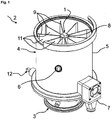
- FIG. 1 an embodiment of the rotary dryer star 1 in a perspective view, installed in a fluidizing apparatus 2, is shown.
- the vortex chamber 4 arranged above the distributor chamber 3 consists of an outer jacket 5, which has a solid particle inlet unit 6 and a solid particle outlet unit 7, and the rotary dryer star 1 which rotates in the vortex chamber 4 and has a cone 8 and partitions 9 arranged thereon. for example, made of sheet metal, aluminum or the like., And divide the vortex chamber 4 into segments.
- the dividing walls 9 extend over the entire height of the vortex chamber 4.
- the dividing walls 9, the outer shell 5, the infill bottom 10, not shown, for example, a grate, the rotary dryer star 1 and a cover, not shown, the vortex chamber 4 form process spaces 11.
- a rotation of the rotary dryer star 1, whereby a precisely defined residence time of the solid particles is set in the swirl chamber 4, by a drive unit 12, for example a servo motor or the like., Generated.
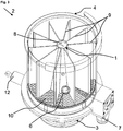
- FIG Fig. 2 A perspective view of the fluidizing apparatus 2 in which the rotary dryer star 1 is installed is shown in FIG Fig. 2 shown.
- the illustration shows the in Fig. 1 already mentioned technical features of the rotary dryer star 1, as well as in Fig. 1
- an inlet opening 10 not shown.
- an opening angle 13 of the process spaces 11, which result from the dividing walls 9 arranged on the cone 8 of the rotary dryer star 1, the inflow base 10, the outer shell 5 and the cover (not shown), which is determined by the positions of the solid particle inlet unit 6 and the solid particle outlet unit 7 is determined to each other.
- the rotary dryer star 1 distributor plate 10 By detachably arranged on the rotary dryer star 1 distributor plate 10, a decoupling of the two units, distribution chamber 3 and whirl chamber 4 is achieved.
- the cone 8 of the rotary dryer star 1 which increases in diameter in the direction of the inflow base 10, serves to calm the flow and thus to form a more stable fluidized bed within the swirl chamber 4.
- the partition walls 9 arranged on the rotary dryer star 1 extend over the entire height of the swirl chamber 4 and are so high that an overflow of the fluidized solid particles during operation of the fluidizing apparatus 2 is not possible. This property of the partition walls 9 increases the product quality, since thus backmixing of differently conditioned solid particles between the individual process spaces 11 is prevented.
- partition walls 9 in the exemplary embodiment at the outer end a bent or angled partition wall end 15 in the direction of rotation 14, whereby on the one hand additional mechanical stability of the partitions 9 of the rotary dryer star 1 is achieved and on the other a sealing of the process spaces 11 against the outer shell. 5 he follows. At the same time, solid particles adhering to the inner wall of the outer shell 5 are scraped off by the partition wall end 15 bent in the direction of rotation 14, thus preventing fouling of the inner wall of the outer shell 5.
- the partition wall 15 between partition 9 and outer shell 5 of the swirl chamber 4 can also be produced by a differently suitable seal. In addition to the ability to use a rotating rotary dryer star 1, there is also the possibility of the outer jacket 5, to connect firmly with the partitions 9 of the rotary dryer star 1 and so perform the entire vortex chamber 4 rotatable.
- Fig. 3 shows a cutaway, perspective view of the fluidizing apparatus 2 and the incorporated therein rotary dryer star 1.
- the distributor plate 10 for example a grate or the like.
- the rotary dryer star 1 in the assembled state of the two functional units, Verteilerhunt3 and whirl chamber 4, clearly visible.
- the distributor plate 10, which is arranged interchangeable and co-rotatable on the rotary dryer star 1, has a varying opening ratio over its surface. This is in Fig. 6 and 7 represented as a uniform structure.
- the opening ratio of the inflow base 10 is adaptable to the solid particles to be conditioned by, for example, different diameters of the openings 16, which may be configured as opening bores, for example, and in the case of a rotating inflow base 10 of the smallest occurring size of the solid particles to be conditioned dependent.
- the distributor plate 10 for example a grate or the like, additionally forms a process chamber closure and thus limits the functional unit vortex chamber 4 with respect to the functional unit distributor chamber 3.
- Fig. 4 1 shows a perspective view of the rotary dryer star 1 according to the invention.
- the rotary dryer star 1 shown in the exemplary embodiment consists of the cone 8, the partitions 9 with dividing wall terminations 15 bent in the direction of rotation 14 and the detachably arranged inflow base 10, for example a grate or the like created in which the solid particles are transported through the vortex chamber 4 with a precisely defined residence time.
- nozzles 17 in the cone 8 of the rotary dryer star 1 are shown.
- the nozzles can also be arranged on the partitions 9 or the outer wall 5 of the vortex chamber 4, not shown here.
- the nozzles enable the spraying of various media, such as gases, liquids or solids. As nozzles, all known in the prior art nozzles can be used.
- Fig. 5 a plan view of the rotary dryer star 1 is shown.
- the rotary dryer star 1 shown has the in Fig. 4 described technical features and also shows the process spaces 11 spanning opening angle 13. Die Process chambers 11 all have the same opening angle 13 in the exemplary embodiment, as a result of which the process spaces 11 are all the same size. However, the process spaces 12 may also have a different opening angle 13 and are therefore no longer identical in size. Furthermore, in Fig. 5 the downwardly widening cone 8 of the rotary dryer star 1 is shown, which leads to a flow calming of the formed fluidized bed.
- the built-in part 18 is arranged in the distribution chamber 3 below the rotary dryer star 1, which is placed in the swirl chamber 4.
- Well visible in the Fig. 6 the uniform opening conditions of the inflow base 10, in this case designed as openings 16, in particular as opening bores, which are designed for the smallest expansion of the solid particles in the conditioning process to be carried out and thus prevent product loss.
- Fig. 7 shows a top view of in Fig. 6 shown assembly of the rotary dryer star 1 and the mounting part 18.
- Fig. 7 Once again, the technical features described above, such as partitions 9, partition walls 15, cones 8 and nozzles 17 are shown.
- the openings 16 of the inflow base 10 are shown here in a constant configuration as opening bores.
- Fig. 8 shows a perspective view of the rotary dryer star 1.
- the process spaces 11 have at the upper end of the partition walls 9, a first cover 21, which rotates with the rotary dryer star 1 with.
- the cover 21 is connected in a gas-tight manner to the partitions 9 here. Due to the cover 21, the height of the process spaces 11 corresponds to the height of the partition walls 9.
- each process space 11 is delimited from the other process spaces 11 and, on the other hand, that the fluidized solid particles from entry into the fluidization apparatus 2 through the solid particles -Entrittstechnik 6 up to the outlet through the solid particle outlet unit 7 each only in a process space 11 dwells, whereby no cross mixing between the different process spaces 11 take place.
- partitions 22 are drawn in the exemplary embodiment, which have the same arrangement here as an example the partitions of the rotary dryer star 1, ie the partitions 22 are aligned with the partitions 9 of the rotary dryer star 1.
- the partitions 22 at the top of a cover 23. This also rotates with the Rotationsstrocknersterns 1 and is at least partially connected to the partitions 22, whereby filter chambers 24 arise.
- the cover 21 per process chamber 11 has two openings, in each of which a filter 25, which consists for example of a metal filter fabric or a filtering fabric or the like, is arranged, which projects into the process space 11.
- the filter cleaning device 26 is supplied via a supply line 27, for example with compressed air.
- at least two filters 25 are provided for each process space 11, whereby it is achieved that a filter 25 can be cleaned while the process gas flows through the other filter 25.
- a process gas control 28 is shown, which consists of a respective control flap 29 or the like.
- control flap 29 can also be replaced by a control valve inserted into the cover 23.
- the cover 23 must be gas-tightly connected to the partitions 22, so that each filter space 24 is assigned to exactly one process space 11.
- the position of the control flap 29 respectively of the control valve determines the volume flow of the fluidizing gas (process gas), which flows through the associated process space 11. In this way, the process gas flow in each process chamber 11 can be individually adjusted or regulated.
- a varying process gas flow is required on entry of the solid particles to be fluidized into a process chamber 11 of the fluidization apparatus 2 by the solid particle inlet unit 6.
- a constant process gas flow is required during the conditioning of the fluidized solid particles.
- Fig. 9 shows various embodiments of the air supply of fluidizing apparatus in a cross section through the single process space of a fluidizing apparatus.
- the air distribution can also be achieved by using the principle of the spouted bed principle instead of by a distributor plate.
- the fluidizing agent is guided through arbitrarily designed inlet slots, preferably circumferential inlet slots, into the process space. Due to the appropriate design thereby a very wide flow mechanical working area and a targeted influencing of the particle movement in the process spaces are possible.
- the air inlets can be designed both "fixed” as well as variable and adjustable.
- the spout layer can be made symmetrical or asymmetrical.
- the process spaces of the fluidizing apparatus can be designed with vertical walls or with any inclined walls inside or / and outside to z. B. to realize upwardly expanding process spaces.
- Process chambers designed as a classical fluidized bed as well as a jet layer can be equipped with all possible nozzle shapes and for all process variants. Also combinations of jet and fluidized beds integrated in a vortex chamber are conceivable.
Abstract
Die Erfindung geht aus von einem Verfahren zur Behandlung von Feststoffpartikeln zum Zwecke der Agglomeration, des Coating, des Layering, der Sprühgranulation oder der Pelletierung in einem Fluidisierungsapparat, in dem die Feststoffpartikel bei Einstellung eines bestimmten Verweilzeitspektrums, besprüht werden, wobei das Besprühen in einem Rotationstrocknerstern (1) zur Segmentierung einer Wirbelkammer (4) in Prozessräume (11), wobei der Rotationstrocknerstern (1) drehbar angeordnet ist und zur Förderung von Feststoffpartikeln entlang einer Förderstrecke Trennwände (9) aufweist, und unterhalb des Rotationstrocknersterns (1) ein Anströmboden (10) lösbar und mitdrehbar an diesem angeordnet ist, und wobei das Verweilzeitspektrum der Feststoffpartikel im Fluidisierungsapparat (2) mindestens eine Spanne von 1:3 (bzw. tRTD90 ≤ 3 tRTD10 alternativ) aufweist.

Description
Die Erfindung geht aus von einem Verfahren zur Behandlung von Feststoffpartikeln mit einem Rotationstrocknerstern zur Segmentierung einer Wirbelkammer in Prozessräume nach der Gattung des Anspruchs 1.The invention is based on a process for the treatment of solid particles with a rotary dryer star for segmenting a vortex chamber in process chambers according to the preamble of
Kontinuierlich betriebene Fluidisierungsapparate zur Konditionierung von Feststoffpartikeln mit einem sich um die vertikale Mittelachse drehenden Rotationstrocknerstern in einer Wirbelkammer, die dadurch in Prozessräume gegliedert ist, sind seit langem Stand der Technik. Insbesondere wird durch den sich um die vertikale Mittelachse drehenden Rotationstrocknerstern in der Wirbelkammer eine konstante und exakt definierte Verweilzeit der Feststoffpartikel im Fluidisierungsapparat erzielt.Continuously operated fluidizing apparatuses for conditioning solid particles with a rotary dryer star rotating about the vertical central axis in a swirl chamber, which is thereby divided into process chambers, have long been state of the art. In particular, a constant and precisely defined residence time of the solid particles in the fluidizing apparatus is achieved by the rotary dryer star rotating about the vertical central axis in the vortex chamber.
Die Patentschrift
In der Patentschrift
Das erfindungsgemäße Verfahren zur Behandlung von Feststoffpartikeln zum Zwecke der Agglomeration, des Coating, des Layering, der Sprühgranulation oder der Pelletierung, hat den Vorteil, dass das Besprühen in einem Rotationstrocknerstern (1) zur Segmentierung einer Wirbelkammer (4) in Prozessräume (11), wobei der Rotationstrocknerstern (1) drehbar angeordnet ist und zur Förderung von Feststoffpartikeln entlang einer Förderstrecke Trennwände (9) aufweist, und unterhalb des Rotationstrocknersterns (1) ein Anströmboden (10) lösbar und mitdrehbar an diesem angeordnet ist, stattfindet und, das Verweilzeitspektrum als Verhältnis der Verweilzeit der Feststoffpartikel mit 10%iger Summenverteilung und 90%iger Summenverteilung im Fluidisierungsapparat (2) beim Besprühen sehr eng eingestellt wird, beispielsweise tRTD,90/tRTD,10 ≤ 3, d. h. die 90 %ige Summenverteilung ist maximal das 3-fache der 10%igen Summenverteilung. Ein Vorteil des Verfahrens mit einem solchen engen Verweilzeitspektrum ist, dass die Produktqualität deutlich im Vergleich zu Verfahren mit größeren Verhältnissen der Verweilzeitspektren gesteigert wird. Mit Verfahren, die zum Beispiel in Apparaten herkömmlicher Bauform ablaufen, können solch enge Verweilzeitspektrum nicht erzielt werden kann. Coating-Prozesse werden in der Pharmaindustrie üblicherweise in Chargenapparaten durchgeführt, um genau definierte Beschichtungszeiten und somit Schichtaufbauten zu gewährleisten. Kontinuierliches Coating in klassischen Wirbelschichtrinnen ist nicht für das Mehrschicht-Coating geeignet, da auch trotz des Einsatzes von Wehreinbauten kein ausreichend enges Verweilzeitspektrum erreicht werden kann. Allerdings ist dieses enge Verweilzeitspektrum zwingend notwendig, wenn insbesondere dünne Schichten auf die Feststoffpartikel aufgetragen werden müssen oder eine sehr gleichmäßige Bedeckung der Feststoffpartikel gefordert wird, unabhängig davon, ob die Behandlung ein- oder mehrschichtig erfolgt. Ein Spektrum, wie beispielsweise
- tRTD,90
- = 2 tRTD,10 mit
- tRTD,...
- Verweilzeit des Feststoffpartikels (10%- bzw. 90%-Wert der Summenverteilung)
- RTD, 90
- = 2 t RTD, 10 with
- t RTD, ...
- Residence time of the solid particle (10% or 90% value of the cumulative distribution)
Das Verweilzeitspektrum kann in einem kontinuierlichen Apparat nicht durch Optimierung des Strömungsprofiles unabhängig von den verfahrenstechnischen Parametern eingestellt werden. Hier gibt es immer Abhängigkeiten, beispielsweise vom Durchsatz, von der Fluidisierungsgeschwindigkeit, von der Schichtmasse sowie von der Partikelgröße und -dichte.The residence time spectrum can not be adjusted in a continuous apparatus by optimizing the flow profile independently of the process parameters. There are always dependencies, for example, the throughput, the fluidization rate, the layer mass and the particle size and density.
Eine direkt einstellbare Verweilzeit kann nur durch Zwangsführung und Ausschluss von Querströmungen gewährleistet werden. Das neuartige Konzept bietet die Möglichkeit, die Verweilzeit unabhängig von sämtlichen verfahrenstechnischen und stofflichen Kenngrößen vorzugeben. Hier kann nun die Verweilzeit direkt über die Drehzahl definiert werden und dadurch die genaue Aufenthalts- und Prozesszeit beschrieben werden. Eine Rückverfolgbarkeit für den Prozessverlauf ist dadurch optimal gegeben, was für Trocknung, Coating, Agglomeration und Sprühgranulation gefordert ist.A directly adjustable dwell time can only be guaranteed by forced operation and exclusion of cross flows. The novel concept offers the possibility to specify the residence time independently of all procedural and material characteristics. Here, the dwell time can be defined directly via the speed and thus the exact residence and process time can be described. Traceability for the course of the process is optimally given, which is required for drying, coating, agglomeration and spray granulation.
Der Rotationstrocknerstern zur Segmentierung einer Wirbelkammer in Prozessräume hat den Vorteil, dass unterhalb des Rotationstrocknersterns ein Anströmboden lösbar an diesem angeordnet ist. Hierzu ist in der Wirbelkammer der Rotationstrocknerstern drehbar angeordnet und weist zur Förderung von Feststoffpartikeln entlang einer Förderstrecke Trennwände oder dgl. auf. Durch das lösbare Anordnen eines Anströmbodens, der beispielsweise als Gitterrost ausgebildet sein kann, unterhalb des Rotationstrocknersterns werden die Nachteile aus dem Stand der Technik überwunden. Noch nicht vollständig fluidisierte Feststoffpartikel können auf den Siebboden absinken oder fallen und werden dort nicht zerstört, sondern werden weiter durch ein Fluidisierungsmedium, wie beispielsweise Luft oder ein Inertgas, angeströmt und konditioniert. Darüber hinaus ist durch das lösbare Anordnen ein Austausch jederzeit möglich, so dass eine Anpassung des Anströmbodens an die Gegebenheiten des Konditionierungsprozesses möglich ist. Die Vorrichtung eignet sich zudem zur Durchführung von jeglichen Granulations- und Coatingprozessen.The rotary dryer star for segmenting a swirl chamber into process spaces has the advantage that below the rotary dryer star, an inflow base is detachably arranged thereon. For this purpose, in the vortex chamber of the rotary dryer star rotatably arranged and has to convey solid particles along a conveyor section partitions or the like. On. By releasably disposing a inflow floor, which may be formed for example as a grid, below the rotary dryer star the disadvantages of the prior art are overcome. Not yet completely fluidized solid particles can fall or fall on the sieve bottom and are not destroyed there, but are further by a fluidizing medium, such as air or an inert gas, is flowed and conditioned. In addition, a replacement is possible at any time by releasably arranging, so that an adaptation of the inflow floor to the conditions of the conditioning process is possible. The device is also suitable for carrying out any granulation and coating processes.
Nach einer vorteilhaften Ausgestaltung des Rotationstrocknersterns ist die Größe der Öffnungen des Anströmbodens von den zu konditionierenden Feststoffpartikeln abhängig. Die Öffnungen des Anströmbodens werden an die jeweiligen Konditionierungsbedingungen angepasst. So wird vermieden, dass bei unterschiedlichen Prozessen Edukte während des Prozessverlaufes zerstört werden.According to an advantageous embodiment of the rotary dryer star, the size of the openings of the inflow base is dependent on the solid particles to be conditioned. The openings of the inflow base are adapted to the respective conditioning conditions. This avoids that educts are destroyed during the course of the process in different processes.
Nach einer diesbezüglichen vorteilhaften Ausgestaltung des Rotationstrocknersterns weisen die Öffnungen eine Größe auf, die von den kleinsten im Konditionierungsprozess auftretenden Feststoffpartikeln abhängig ist.According to a related advantageous embodiment of the rotary dryer star, the openings have a size that is dependent on the smallest occurring in the conditioning process solid particles.
Nach einer zusätzlichen vorteilhaften Ausgestaltung des Rotationstrocknersterns ist an dem Rotationstrocknerstern mindestens eine Düse oder dgl. angeordnet. Durch die Anordnung einer Düse an den Rotationstrocknerstern ist die Möglichkeit gegeben, Feststoffpartikel während der Verweilzeit in der Wirbelkammer in verschiedenster Art und Weise zu konditionieren. Es können bspw. Flüssigkeiten aufgesprüht oder unterschiedliche Gase zugemischt werden um die Feststoffpartikel zu verändern bzw. zu konditionieren. Darüber hinaus können mittels Feststoffdüsen bspw. auch Kunststoffe auf die Feststoffpartikel aufgesprüht werden. Die lokale Anordnung der Düsen kann in der Außenwand der Wirbelkammer oder am Rotationstrocknerstern erfolgen. Essenziell wichtig ist bei allen Prozessvarianten, dass eine Flüssigkeit über die Düsen, z. B. Sprühdüsen, in die Prozessräume eingebracht wird. Das Medium, beispielsweise eine Flüssigkeit, kann als Lösung, Suspension, Dispersion, Emulsion, Schmelze usw. mittels der Düse eingebracht werden. In jedem Fall wird kontinuierlich mindestens ein Feststoff über die beliebig gestaltete Feststoffpartikel-Eintrittseinheit zugeführt. Die sich in den einzelnen Prozessräumen befindlichen Feststoffe werden nun mittels mindestens einer Düse mit Medien, z. B. Flüssigkeiten, benetzt. Je nach den vorliegenden Prozessbedingungen und Produkteigenschaften des Feststoffes sowie des Mediums werden die fluidisierten Partikel benetzt. Simultan findet ein Verfestigungsprozess in den Prozessräumen statt, wodurch die Feststoffe entweder miteinander verbunden werden (Agglomerationsprozess) oder sich die über die Sprühflüssigkeit(en) zugeführten Feststoffe an der Partikeloberfläche anlagern (Coating, Layering, Sprühgranulation, Pelletierung). Über die Sprühflüssigkeit zugeführte Lösungsmittel, wie Wasser oder org. Lösungsmittel (Ethanol, Isopropanol oder dgl.), verdampfen und werden mit dem Fluidisierungsmittel (Luft, Stickstoff oder dgl.) abgeführt.According to an additional advantageous embodiment of the rotary dryer star, at least one nozzle or the like is arranged on the rotary dryer star. The arrangement of a nozzle on the rotary dryer star the possibility is given to condition solid particles during the residence in the vortex chamber in a variety of ways. For example, liquids can be sprayed on or different gases mixed in order to change or condition the solid particles. In addition, by means of solid nozzles, for example, plastics can also be sprayed onto the solid particles. The local arrangement of the nozzles can be done in the outer wall of the vortex chamber or on the rotary dryer star. Essentially important in all process variants, that a liquid through the nozzles, z. B. spray nozzles, is introduced into the process spaces. The medium, for example a liquid, can be introduced as a solution, suspension, dispersion, emulsion, melt, etc., by means of the nozzle. In any case, at least one will continuously Solid supplied via the arbitrarily designed solid particle inlet unit. The located in the individual process spaces solids are now using at least one nozzle with media, eg. As liquids wetted. Depending on the existing process conditions and product properties of the solid and the medium, the fluidized particles are wetted. Simultaneously, a solidification process takes place in the process chambers, whereby the solids are either connected to each other (agglomeration process) or accumulate on the spray liquid (s) supplied solids on the particle surface (coating, layering, spray granulation, pelleting). Solvents supplied via the spraying liquid, such as water or org. Solvent (ethanol, isopropanol or the like), evaporate and are removed with the fluidizing agent (air, nitrogen or the like.).
Auf diese Weise lassen sich eine Vielzahl von Prozessvarianten zur Herstellung oder Funktionalisierung von Partikelsystemen durchführen. Beispielsweise kann ein durch Kristallisation hergestellter pulvriger (feindisperser) pharmazeutischer Wirkstoff (z. B. Paracetamol) kontinuierlich zugeführt und in den Prozessräumen mit einem wässrigen Bindemittel (z. B. Stärkekleister) besprüht werden. Diese Binderzuführung führt zu einer Agglomeration der Pulver und es entstehen direkt frei fließfähige Agglomerate mit definierter Struktur. Die Vorrichtung gewährleistet einen genau definierten Bindemittelgehalt im Endprodukt. Außerdem ist auch eine sehr gleichmäßige und reproduzierbare Einstellung der Endfeuchte möglich, weil es im Vergleich zu konventionell gestalteten kontinuierlichen Granulatoren keine Inhomogenität durch Verweilzeitspektren gibt.In this way, a variety of process variants for the production or functionalization of particle systems can be performed. For example, a powdery (finely dispersed) pharmaceutical active ingredient (eg acetaminophen) prepared by crystallization can be continuously fed and sprayed in the process spaces with an aqueous binder (eg starch paste). This binder feed leads to an agglomeration of the powders and directly free-flowing agglomerates with a defined structure are formed. The device ensures a well-defined binder content in the final product. In addition, a very uniform and reproducible adjustment of the final moisture content is possible because there is no inhomogeneity by retention time spectra in comparison to conventionally designed continuous granulators.
Eine andere Anwendungsvariante ist beispielsweise das kontinuierliche Coating. Hier kann z. B. ein vorgranulierter, tablettierter oder pelletierter Rohstoff (Granulate, Agglomerate, Pellets, Tabletten oder dgl.) mit einem Überzug versehen werden. Als Beispiele seien hier die Beschichtung von Düngemittelgranulaten oder Waschmittelkomponenten mit Barrieren gegen Feuchtigkeit (Hydrophobierung), der Überzug von Trägerpellets mit pharmazeutischen Wirkstoffen (drug-layering), das funktionelle Coating von pharmazeutischen Wirkstoffen mit z. B. Polymeren zur Änderung des Freisetzungsprofiles (SR-Coating) oder die Beschichtung von Enzymgranulaten mit Additiven zur Verbesserung der Lager- und Pelletierstabilität genannt.Another application variant is for example the continuous coating. Here can z. As a pre-granulated, tableted or pelletized raw material (granules, agglomerates, pellets, tablets or the like.) Are provided with a coating. Examples include the coating of fertilizer granules or detergent components with barriers to moisture (hydrophobing), the coating of carrier pellets with pharmaceutical drugs (drug-layering), the functional coating of pharmaceutical agents with z. B. polymers for changing the release profile (SR coating) or the coating of enzyme granules with additives to improve the storage and pelleting stability called.
In allen Anwendungsfällen erlaubt die Vorrichtung, dass Einbringen von Medien, beispielsweise Flüssigkeiten, jeglicher Form sowie unter Anwendung sämtlicher bekannter Sprüheinrichtungen (z. B. Druck-, Zweistoff-, Ultraschalldüsen oder dgl.) unabhängig von deren räumlicher Orientierung und Anordnung (Eindüsung von oben, unten, geneigt, tangential oder ähnlichem). Auch die Anzahl der Sprüheinrichtungen ist variabel. Beispielsweise ist es denkbar, verschiedene Flüssigkeiten simultan über mehrere Düsen in jeweils einem Prozessraum einzutragen oder aber auch Mehrstoffdüsen (paralleles Versprühen von Flüssigkeiten) zu nutzen.In all applications, the device allows the introduction of media, for example liquids, of any shape and using all known spray devices (eg pressure, binary, ultrasonic nozzles or the like.) Regardless of their spatial orientation and arrangement (injection from above , down, inclined, tangential or similar). The number of sprayers is variable. For example, it is conceivable to enter different liquids simultaneously via a plurality of nozzles in each case in a process space or else to use multi-substance nozzles (parallel spraying of liquids).
Apparatetechnisch ist es auch möglich, dass ein Prozessraum während seiner Bewegung von der Feststoffpartikel-Eintrittseinheit zur Feststoffpartikel-Austrittseinheit nacheinander mit mehreren Flüssigkeiten versorgt wird. Somit ist auch ein genau kontrollierter und gesteuerter Aufbau von z. B. Mehrschichtpellets möglich. Dazu werden die Düsen einfach umschaltbar an mehrere Versorgungssysteme angeschlossen.In terms of apparatus, it is also possible for a process space to be supplied in succession with a plurality of liquids during its movement from the solid particle inlet unit to the solid particle outlet unit. Thus, a well-controlled and controlled construction of z. B. multi-layer pellets possible. For this purpose, the nozzles are simply connected switchable to multiple supply systems.
Nach einer zusätzlichen vorteilhaften Ausgestaltung des Rotationstrocknersterns sind die zur Förderung von Feststoffpartikeln entlang einer Förderstrecke dienenden Trennwände mit einem Außenmantel der Wirbelkammer fest verbunden.According to an additional advantageous embodiment of the rotary dryer star serving for the promotion of solid particles along a conveyor section partitions with an outer shell of the vortex chamber are firmly connected.
Nach einer zusätzlichen vorteilhaften Ausgestaltung des Rotationstrocknersterns weist mindestens ein Prozessraum eine Abdeckung und/oder mindestens einen Filter auf. Durch die Anordnung einer Abdeckung oberhalb des Rotationstrocknersterns wird ein Prozessraumabschluss nach oben hin gebildet. So wird ein Überlaufen von fluidisierten Feststoffpartikeln von einem Prozessraum in einen anderen Prozessraum während des Betriebs des Fluidisierungsapparates verhindert, wodurch die Produktqualität gesteigert wird, da somit eine Rückvermischung von unterschiedlich konditionierten Feststoffpartikeln zwischen den einzelnen Prozessräumen unterbunden wird.According to an additional advantageous embodiment of the rotary dryer star, at least one process space has a cover and / or at least one filter. By arranging a cover above the rotary dryer star, a process space closure is formed upwards. Thus, an overflow of fluidized solid particles from one process space into another process space during operation of the fluidization apparatus is prevented, whereby the product quality is increased, since thus backmixing of differently conditioned solid particles between the individual process spaces is prevented.
Nach einer diesbezüglich vorteilhaften Ausgestaltung des Rotationstrocknersterns ist der mindestens eine Filter an der mindestens einen Abdeckung angeordnet. Die Anordnung eines Filters in der Abdeckung des Prozessraums hat den Vorteil, dass der Filter verhindert, dass fluidisierte Feststoffpartikel aus dem jeweiligen Prozessraum ausgetragen werden und dadurch in andere Segmente gelangen können. Weiterhin werden dadurch Entmischungseffekte oder Separierungen innerhalb der segmentierten Prozessräume unterbunden.According to an advantageous embodiment of the rotary dryer star, the at least one filter is arranged on the at least one cover. The arrangement of a filter in the cover of the process chamber has the advantage that the filter prevents fluidized solid particles from being discharged from the respective process space and thereby being able to reach other segments. Furthermore, demixing effects or separations within the segmented process spaces are thereby prevented.
Nach einer zusätzlichen vorteilhaften Ausgestaltung des Rotationstrocknersterns weist mindestens ein Prozessraum eine Prozessgasregelung auf. Diese ist vorteilhafterweise oberhalb des Rotationstrocknersterns und einer ersten Abdeckung angeordnet, mit der der Prozessgasstrom in jedem Prozessraum einzeln reguliert werden kann. Die Prozessgasregelung besteht zum einen aus einem zusätzlichen Stern (Filterräume) zur Segmentierung des durch die Prozessräume und aus der Abdeckung strömenden Prozessgases. Oberhalb dieses sternförmigen Bauteils befindet sich zum anderen vorteilhaft für jeden Prozessraum jeweils eine Regelklappe oder dgl. zur Regelung des Prozessgasstroms. Vorteilhaft kann auf diese Weise die Prozessgasströmung durch jeden Prozessraum einzeln parametriert werden bzw. ggf. zusätzlich oder alternativ zur Luftmengenverteilung durch die Anströmbodenkonstruktion. Dies stellt eine Verbesserung des momentanen Standes der Technik dar, da bei einer Konditionierung mittels der in jedem Prozessraum angeordneten Düsen während einer Rotation es unterschiedlicher Prozessgasströmungen bedarf. Außerdem kann sich eine Regelung der Prozessgasströmung insbesondere bei den Befüll- und Entleervorgängen der jeweiligen Prozessräume günstig auswirken.According to an additional advantageous embodiment of the rotary dryer star, at least one process chamber has a process gas control. This is advantageously arranged above the rotary dryer star and a first cover, with which the process gas flow in each process space can be regulated individually. The process gas control consists on the one hand of an additional star (filter chambers) for segmenting the process gas flowing through the process chambers and from the cover. On the other hand, above this star-shaped component there is advantageously a control flap or the like for each process chamber for controlling the process gas flow. Advantageously, in this way, the process gas flow can be individually parameterized by each process space or possibly additionally or alternatively to the air volume distribution through the Anströmmbodenkonstruktion. This represents an improvement of the current state of the art, since with conditioning by means of the nozzles arranged in each process chamber during a rotation, different process gas flows are required. In addition, a regulation of the process gas flow can have a favorable effect, in particular during the filling and emptying processes of the respective process spaces.
Weitere Vorteile und vorteilhafte Ausgestaltung der Erfindung sind der nachfolgenden Beschreibung, den Ansprüchen und den Zeichnungen entnehmbar.Further advantages and advantageous embodiment of the invention are the following description, the claims and the drawings removed.
Bevorzugte Ausführungsbeispiele des erfindungsgemäßen Verfahrens sind in der Zeichnung dargestellt und werden im Folgenden näher erläutert. Es zeigen
- Fig. 1
- eine perspektivische Darstellung eines Fluidisierungsapparates mit dem eingebauten Rotationstrocknerstern,
- Fig. 2
- eine perspektivische Darstellung auf einen Fluidisierungsapparat mit dem eingebauten Rotationstrocknerstern,
- Fig. 3
- eine aufgeschnittene, perspektivische Darstellung eines Fluidisierungsapparates mit dem eingebauten Rotationstrocknerstern,
- Fig. 4
- eine perspektivische Ansicht des Rotationstrocknersterns,
- Fig. 5
- eine Aufsicht auf den Rotationstrocknerstern,
- Fig. 6
- eine perspektivische Darstellung eines Zusammenbaus des Rotationstrocknersterns und eines Einbauteils der Verteilerkammer,
- Fig. 7
- eine Aufsicht auf den in
Fig. 6 dargestellten Zusammenbau, - Fig. 8
- eine perspektivische Darstellung des Rotationstrocknersterns mit Abdeckung, Filtern und Prozessgasregelung und
- Fig. 9
- einen Querschnitt verschiedener Ausführungsformen der Luftzuführung von Fluidisierungsapparaten.
- Fig. 1
- a perspective view of a fluidizing apparatus with the built-in rotary dryer star,
- Fig. 2
- a perspective view of a fluidizing apparatus with the built-in rotary dryer star,
- Fig. 3
- a cutaway, perspective view of a fluidizing apparatus with the built-in rotary dryer star,
- Fig. 4
- a perspective view of the rotary dryer star,
- Fig. 5
- a view of the rotary dryer star,
- Fig. 6
- a perspective view of an assembly of the rotary dryer star and a built-in part of the distribution chamber,
- Fig. 7
- a supervision on the in
Fig. 6 illustrated assembly, - Fig. 8
- a perspective view of the rotary dryer star with cover, filters and process gas control and
- Fig. 9
- a cross section of various embodiments of the air supply of fluidizing apparatus.
In
Eine perspektivische Darstellung auf den Fluidisierungsapparat 2, in welchem der Rotationstrocknerstern 1 eingebaut ist, ist in der
In
Eine perspektivische Darstellung des Zusammenbaus des Rotationstrocknersterns 1, mit Kegel 8 und Trennwänden 9, ist in
Alle hier dargestellten Merkmale können sowohl einzeln als auch in beliebiger Kombination miteinander erfindungswesentlich sein.All features shown here may be essential to the invention both individually and in any combination.
- 11
- RotationstrocknersternRotary dryer Star
- 22
- FluidisierungsapparatFluidisierungsapparat
- 33
- Verteilerkammerdistribution chamber
- 44
- Wirbelkammerswirl chamber
- 55
- Außenmantelouter sheath
- 66
- Feststoffpartikel-EintrittseinheitSolid particle inlet unit
- 77
- Feststoffpartikel-AustritteinheitSolid particles discharge unit
- 88th
- Kegelcone
- 99
- Trennwandpartition wall
- 1010
- AnströmbodenInlet floor
- 1111
- Prozessräumeprocess spaces
- 1212
- Antriebseinheitdrive unit
- 1313
- Öffnungswinkelopening angle
- 1414
- Drehrichtungdirection of rotation
- 1515
- Trennwandabschluss (Dichtung)Partition wall seal
- 1616
- Öffnungenopenings
- 1717
- Düsejet
- 1818
- Einbauteilfitting
- 1919
- LuftverteilerplatteAir distribution plate
- 2020
- Gestellframe
- 2121
- Abdeckungcover
- 2222
- Trennwandpartition wall
- 2323
- Abdeckungcover
- 2424
- Filterraumfilter chamber
- 2525
- Filterfilter
- 2626
- FilterreinigungsvorrichtungFilter cleaning device
- 2727
- Zuleitungsupply
- 2828
- ProzessgasregelungProcess gas control
- 2929
- Regelklappecontrol flap
Claims (1)
dadurch gekennzeichnet,
characterized,
Applications Claiming Priority (3)
| Application Number | Priority Date | Filing Date | Title |
|---|---|---|---|
| DE102013005920 | 2013-04-03 | ||
| PCT/DE2014/000162 WO2014161525A2 (en) | 2013-04-03 | 2014-04-03 | Rotary dryer star and method for treating solid particles |
| EP14728814.6A EP2981352B1 (en) | 2013-04-03 | 2014-04-03 | Rotary dryer star for treating solid particles |
Related Parent Applications (2)
| Application Number | Title | Priority Date | Filing Date |
|---|---|---|---|
| EP14728814.6A Division EP2981352B1 (en) | 2013-04-03 | 2014-04-03 | Rotary dryer star for treating solid particles |
| EP14728814.6A Division-Into EP2981352B1 (en) | 2013-04-03 | 2014-04-03 | Rotary dryer star for treating solid particles |
Publications (3)
| Publication Number | Publication Date |
|---|---|
| EP3075445A1 EP3075445A1 (en) | 2016-10-05 |
| EP3075445A9 true EP3075445A9 (en) | 2016-11-30 |
| EP3075445B1 EP3075445B1 (en) | 2019-07-24 |
Family
ID=50897313
Family Applications (2)
| Application Number | Title | Priority Date | Filing Date |
|---|---|---|---|
| EP16001042.7A Active EP3075445B1 (en) | 2013-04-03 | 2014-04-03 | Method for the treatment of solid particles |
| EP14728814.6A Active EP2981352B1 (en) | 2013-04-03 | 2014-04-03 | Rotary dryer star for treating solid particles |
Family Applications After (1)
| Application Number | Title | Priority Date | Filing Date |
|---|---|---|---|
| EP14728814.6A Active EP2981352B1 (en) | 2013-04-03 | 2014-04-03 | Rotary dryer star for treating solid particles |
Country Status (7)
| Country | Link |
|---|---|
| US (1) | US10132565B2 (en) |
| EP (2) | EP3075445B1 (en) |
| JP (1) | JP6379177B2 (en) |
| CN (1) | CN105358244B (en) |
| DE (1) | DE102014004815A1 (en) |
| ES (2) | ES2745476T3 (en) |
| WO (1) | WO2014161525A2 (en) |
Families Citing this family (15)
| Publication number | Priority date | Publication date | Assignee | Title |
|---|---|---|---|---|
| US9839891B2 (en) * | 2013-09-27 | 2017-12-12 | Bexo As | Fluid bed classification elements |
| US10011939B2 (en) * | 2015-08-31 | 2018-07-03 | Ki Kwon Park | Partitioning apparatus for washer/dryer combination |
| PH12016000174A1 (en) * | 2016-05-06 | 2017-11-27 | Bigboss Cement Inc | An additive and a method for producing a cement composition |
| CN106733510B (en) * | 2016-11-29 | 2019-04-05 | 上海弘枫实业有限公司 | A kind of coating unit with wing passage |
| CN109470593B (en) * | 2017-09-07 | 2024-03-12 | 中冶长天国际工程有限责任公司 | Absolute method on-line moisture detector and detection method |
| DE102018208932A1 (en) | 2018-06-06 | 2019-12-12 | Glatt Gesellschaft Mit Beschränkter Haftung | Inlet bottom for a fluidizing apparatus |
| CN108636653A (en) * | 2018-06-29 | 2018-10-12 | 陕西图灵电子科技有限公司 | Ultrasonic spray equipment |
| DE102019200304A1 (en) | 2019-01-11 | 2020-07-16 | Glatt Gmbh | Filter system for purifying a gas stream laden with particles and arrangement for purifying a gas stream laden with particles of a fluidizing apparatus by means of a filter system |
| WO2021121557A1 (en) | 2019-12-17 | 2021-06-24 | Wacker Chemie Ag | Fluidized-bed reactor for the control of the dwell time distribution in continuously operated fluidized beds |
| EP4171518A1 (en) | 2020-06-26 | 2023-05-03 | Aprecia Pharmaceuticals LLC | Rapidly-orodispersible tablets having an interior cavity |
| CN111840590B (en) * | 2020-07-21 | 2021-12-07 | 徐州远方药食同源健康产业研究院有限公司 | Centrifugal force dehydration classifiable-based sterilization device for producing band-aid |
| DE102021200161A1 (en) * | 2021-01-11 | 2022-07-14 | Glatt Gesellschaft Mit Beschränkter Haftung | Fluidizing apparatus and method for treating particulate matter |
| RU2770524C1 (en) * | 2021-09-22 | 2022-04-18 | Федеральное государственное бюджетное образовательное учреждение высшего образования «Тамбовский государственный технический университет» (ФГБОУ ВО «ТГТУ») | Installation for drying pasty materials in a swirling suspended layer of inert bodies |
| CN113680462B (en) * | 2021-10-27 | 2021-12-31 | 苏州锦艺新材料科技有限公司 | Production process of spherical silicon micropowder |
| CN114562856A (en) * | 2022-03-07 | 2022-05-31 | 江西省千目高新科技有限公司 | Dry strorage device of chinese-medicinal material for animal health care |
Family Cites Families (35)
| Publication number | Priority date | Publication date | Assignee | Title |
|---|---|---|---|---|
| AT220075B (en) | 1957-06-14 | 1962-03-12 | Hermann Orth | Fluidized bed and flight bed dryers |
| DE1227840B (en) | 1960-08-25 | 1966-10-27 | Haas Friedrich Maschf | Continuously working fluid bed dryer |
| AT252874B (en) | 1963-04-13 | 1967-03-10 | Zdenek Ing Kabatek | Fluidized bed facility |
| GB1030678A (en) * | 1964-01-25 | 1966-05-25 | Terenzio Bersano | Apparatus for the cooling or heating, by continuous air circulation, of granulated materials |
| GB1072908A (en) | 1964-12-17 | 1967-06-21 | Head Wrightson & Co Ltd | Improvements in and relating to fluidizing beds |
| US3724090A (en) | 1970-06-08 | 1973-04-03 | Smitherm Industries | Apparatus for processing particulate solids |
| AT331189B (en) | 1973-05-28 | 1976-08-10 | Chemiefaser Lenzing Ag | METHOD AND DEVICE FOR DRYING LOOSE FIBER MATERIAL |
| US4246836A (en) | 1975-11-05 | 1981-01-27 | Smitherm Industries, Inc. | Apparatus for processing particulate solids |
| US4096792A (en) | 1975-11-05 | 1978-06-27 | Smitherm Industries, Inc. | Continuous coffee roasting apparatus |
| DD136454A1 (en) | 1978-05-16 | 1979-07-11 | Lothar Moerl | DEVICE FOR SOLVENT REMOVAL |
| DD136927B1 (en) | 1978-05-22 | 1986-03-26 | Schwermaschinenbaukomb Ernst T | ANROASTIVE FLOOR FOR SWIVEL LAYER APPARATUS |
| DK148817C (en) | 1979-02-05 | 1986-04-28 | Cabinplant As | DEVICE FOR CONTINUOUS COOKING OF SOLID SUBSTANCES, NECESSARY FOOD |
| US4425865A (en) * | 1980-11-17 | 1984-01-17 | Saat- Und Erntetechnik Gmbh | Method for the homogeneous complete encapsulation of individual grains of pourable material and apparatus for its production |
| JPS5943216B2 (en) * | 1981-06-23 | 1984-10-20 | 株式会社奈良機械製作所 | Mixing/granulating/drying machine |
| US4426936A (en) | 1982-04-21 | 1984-01-24 | General Motors Corporation | Method and apparatus for disposal of thermoplastic waste in a fluidized bed reactor |
| DD236159A1 (en) | 1985-04-11 | 1986-05-28 | Kali Chemie Veb | DEVICE FOR CONTINUOUS DRYING OF PIGMENTS |
| DE3519750A1 (en) | 1985-06-01 | 1986-12-04 | H. Orth GmbH, 6737 Böhl-Iggelheim | METHOD AND DEVICE FOR DRYING HEAT-SENSITIVE PRODUCTS WITH HIGH INITIAL HUMIDITY |
| CH665473A5 (en) | 1985-07-18 | 1988-05-13 | Schweizerische Viscose | Crystallising and drying PET polymer granules - by feeding continuously into rising current of hot air where dust is removed and dried prod. falls out |
| JPH03284343A (en) | 1990-03-30 | 1991-12-16 | Okawara Mfg Co Ltd | Fluidized bed treatment apparatus |
| JPH0570639A (en) | 1991-09-12 | 1993-03-23 | Mitsui Petrochem Ind Ltd | Cycloolefin resin composition |
| US5470387A (en) * | 1994-03-07 | 1995-11-28 | Niro A/S | Continuous multicell process and apparatus for particle coating including particle recirculation |
| JPH07265683A (en) | 1994-04-01 | 1995-10-17 | Freunt Ind Co Ltd | Fluidized bed device and granulating, coating and drying method of granular body |
| JP3417669B2 (en) * | 1994-07-14 | 2003-06-16 | 塩野義製薬株式会社 | Tank moving type fluidized drying equipment |
| JP3271880B2 (en) * | 1995-10-09 | 2002-04-08 | ホソカワミクロン株式会社 | Powder processing equipment |
| DE19706434A1 (en) | 1997-02-19 | 1998-08-20 | Glatt Ingtech Gmbh | Inflow floor for fluidized bed process plants |
| EP0965279A3 (en) | 1998-06-18 | 2000-04-12 | Jobst O. A. Zoellner | Device and method for the thermic treatment of grain products |
| JP2001219050A (en) * | 2000-02-10 | 2001-08-14 | Bayer Yakuhin Ltd | Fluidized bed granulating/coating apparatus and fluidized bed granulating/coating method |
| JP4663887B2 (en) * | 2000-05-01 | 2011-04-06 | フロイント産業株式会社 | Fluidized bed granulation coating apparatus and fluidized bed granulation coating method |
| EP1584371A1 (en) | 2004-04-07 | 2005-10-12 | Urea Casale S.A. | Fluid bed granulation process and apparatus |
| WO2006067544A1 (en) | 2004-12-23 | 2006-06-29 | Collette Nv | Fluid bed apparatus and method of operating such apparatus |
| WO2007124745A1 (en) | 2006-05-02 | 2007-11-08 | Niro A/S | Agglomeration apparatus and method for producing agglomerated particles |
| US7883039B2 (en) | 2007-02-27 | 2011-02-08 | Collette Nv | Continuous granulating and drying apparatus including measurement units |
| WO2010016342A1 (en) * | 2008-08-05 | 2010-02-11 | フロイント産業株式会社 | Fluidized bed device |
| DE202010011968U1 (en) | 2010-08-30 | 2010-12-23 | Ava - Anhaltinische Verfahrens- Und Anlagentechnik Gmbh | Device for continuous drying and functionalization of digestate |
| RU2602888C2 (en) | 2011-05-12 | 2016-11-20 | Глатт Инженьертехник Гмбх | Device for continuous treatment of solid substances in apparatus with fluidised bed |
-
2014
- 2014-04-03 US US14/781,979 patent/US10132565B2/en active Active
- 2014-04-03 EP EP16001042.7A patent/EP3075445B1/en active Active
- 2014-04-03 ES ES16001042T patent/ES2745476T3/en active Active
- 2014-04-03 ES ES14728814T patent/ES2732292T3/en active Active
- 2014-04-03 CN CN201480019757.3A patent/CN105358244B/en active Active
- 2014-04-03 DE DE102014004815.2A patent/DE102014004815A1/en not_active Withdrawn
- 2014-04-03 WO PCT/DE2014/000162 patent/WO2014161525A2/en active Application Filing
- 2014-04-03 JP JP2016505704A patent/JP6379177B2/en active Active
- 2014-04-03 EP EP14728814.6A patent/EP2981352B1/en active Active
Also Published As
| Publication number | Publication date |
|---|---|
| US10132565B2 (en) | 2018-11-20 |
| JP2016519748A (en) | 2016-07-07 |
| EP3075445B1 (en) | 2019-07-24 |
| JP6379177B2 (en) | 2018-08-22 |
| US20160047599A1 (en) | 2016-02-18 |
| ES2732292T3 (en) | 2019-11-21 |
| CN105358244A (en) | 2016-02-24 |
| WO2014161525A2 (en) | 2014-10-09 |
| EP3075445A1 (en) | 2016-10-05 |
| DE102014004815A1 (en) | 2014-10-09 |
| EP2981352B1 (en) | 2019-05-15 |
| WO2014161525A3 (en) | 2015-03-19 |
| ES2745476T3 (en) | 2020-03-02 |
| CN105358244B (en) | 2019-12-10 |
| EP2981352A2 (en) | 2016-02-10 |
Similar Documents
| Publication | Publication Date | Title |
|---|---|---|
| EP2981352B1 (en) | Rotary dryer star for treating solid particles | |
| DE3334543C2 (en) | ||
| EP2707127B1 (en) | Device for the continuous treatment of solids in a fluidised bed apparatus | |
| DE4000572C1 (en) | ||
| EP0370167B1 (en) | Fluidized-bed apparatus for the production and/or the treatment of granular materials | |
| DE3609133C2 (en) | ||
| DE3337830A1 (en) | GRANULATING AND COATING DEVICE | |
| DE4118433C2 (en) | Fluid bed apparatus for treating particulate goods | |
| DE102013005921A1 (en) | Fluidisierungsapparat | |
| EP0089486B1 (en) | Column of fluidised chambers | |
| EP1407814B1 (en) | Process and apparatus with a fluidised bed apparatus for producing granules | |
| EP2352579B1 (en) | Method and apparatus for the treatment of fine-grained material in a spouted bed | |
| WO1987000767A1 (en) | Device for processing substances in a flow of gas | |
| EP1288600B1 (en) | Apparatus for drying bulk material in counter flow with a gaseous fluid | |
| DE10146778A1 (en) | Production of compact solid particles, e.g. granules, in continuously operating fluidized layer, involves using fluidized layer, feeding raw material to part of layer, and feeding material produced into fluidized layer | |
| DE3007292C2 (en) | Method and device for the continuous production of granules formed from the dry matter content of a solution or suspension | |
| EP3953128A1 (en) | Device for cooling particulate materials | |
| EP2490797B1 (en) | Device for treating particulate matter having a two-pass flow floor | |
| AT392015B (en) | STIRRING DEVICE FOR FLUIDIZED LAYERS WITH CLASSIFYING DUCT | |
| DE19700029B4 (en) | Fluidized bed apparatus | |
| EP3801862A1 (en) | Device and method for producing and treating granulate, and adapter connecting piece for connecting a granulator which generates a granulate and a fluidizing device | |
| DE19528584A1 (en) | Fluidised bed appts. to treat granular material e.g for coating tablets - with concentric rings of feeder plates in base to give uniform treatment conditions | |
| EP3953028A1 (en) | Device for producing granular materials or extrudates | |
| DE2940263B2 (en) | Process for the uniform, closed surface coating of individual grains of pourable goods and device for its implementation | |
| DD241246A1 (en) | SWIVEL LAYERING APPARATUS FOR CONVERTING CORE GUARANTEES |
Legal Events
| Date | Code | Title | Description |
|---|---|---|---|
| PUAI | Public reference made under article 153(3) epc to a published international application that has entered the european phase |
Free format text: ORIGINAL CODE: 0009012 |
|
| 17P | Request for examination filed |
Effective date: 20160510 |
|
| AC | Divisional application: reference to earlier application |
Ref document number: 2981352 Country of ref document: EP Kind code of ref document: P |
|
| AK | Designated contracting states |
Kind code of ref document: A1 Designated state(s): AL AT BE BG CH CY CZ DE DK EE ES FI FR GB GR HR HU IE IS IT LI LT LU LV MC MK MT NL NO PL PT RO RS SE SI SK SM TR |
|
| AX | Request for extension of the european patent |
Extension state: BA ME |
|
| STAA | Information on the status of an ep patent application or granted ep patent |
Free format text: STATUS: EXAMINATION IS IN PROGRESS |
|
| 17Q | First examination report despatched |
Effective date: 20170314 |
|
| GRAP | Despatch of communication of intention to grant a patent |
Free format text: ORIGINAL CODE: EPIDOSNIGR1 |
|
| STAA | Information on the status of an ep patent application or granted ep patent |
Free format text: STATUS: GRANT OF PATENT IS INTENDED |
|
| INTG | Intention to grant announced |
Effective date: 20190312 |
|
| GRAS | Grant fee paid |
Free format text: ORIGINAL CODE: EPIDOSNIGR3 |
|
| GRAA | (expected) grant |
Free format text: ORIGINAL CODE: 0009210 |
|
| STAA | Information on the status of an ep patent application or granted ep patent |
Free format text: STATUS: THE PATENT HAS BEEN GRANTED |
|
| AC | Divisional application: reference to earlier application |
Ref document number: 2981352 Country of ref document: EP Kind code of ref document: P |
|
| AK | Designated contracting states |
Kind code of ref document: B1 Designated state(s): AL AT BE BG CH CY CZ DE DK EE ES FI FR GB GR HR HU IE IS IT LI LT LU LV MC MK MT NL NO PL PT RO RS SE SI SK SM TR |
|
| REG | Reference to a national code |
Ref country code: GB Ref legal event code: FG4D Free format text: NOT ENGLISH |
|
| REG | Reference to a national code |
Ref country code: CH Ref legal event code: EP |
|
| REG | Reference to a national code |
Ref country code: DE Ref legal event code: R096 Ref document number: 502014012293 Country of ref document: DE |
|
| REG | Reference to a national code |
Ref country code: AT Ref legal event code: REF Ref document number: 1157542 Country of ref document: AT Kind code of ref document: T Effective date: 20190815 |
|
| REG | Reference to a national code |
Ref country code: IE Ref legal event code: FG4D Free format text: LANGUAGE OF EP DOCUMENT: GERMAN |
|
| REG | Reference to a national code |
Ref country code: SE Ref legal event code: TRGR |
|
| REG | Reference to a national code |
Ref country code: NL Ref legal event code: MP Effective date: 20190724 |
|
| REG | Reference to a national code |
Ref country code: LT Ref legal event code: MG4D |
|
| PG25 | Lapsed in a contracting state [announced via postgrant information from national office to epo] |
Ref country code: HR Free format text: LAPSE BECAUSE OF FAILURE TO SUBMIT A TRANSLATION OF THE DESCRIPTION OR TO PAY THE FEE WITHIN THE PRESCRIBED TIME-LIMIT Effective date: 20190724 Ref country code: NL Free format text: LAPSE BECAUSE OF FAILURE TO SUBMIT A TRANSLATION OF THE DESCRIPTION OR TO PAY THE FEE WITHIN THE PRESCRIBED TIME-LIMIT Effective date: 20190724 Ref country code: PT Free format text: LAPSE BECAUSE OF FAILURE TO SUBMIT A TRANSLATION OF THE DESCRIPTION OR TO PAY THE FEE WITHIN THE PRESCRIBED TIME-LIMIT Effective date: 20191125 Ref country code: LT Free format text: LAPSE BECAUSE OF FAILURE TO SUBMIT A TRANSLATION OF THE DESCRIPTION OR TO PAY THE FEE WITHIN THE PRESCRIBED TIME-LIMIT Effective date: 20190724 Ref country code: FI Free format text: LAPSE BECAUSE OF FAILURE TO SUBMIT A TRANSLATION OF THE DESCRIPTION OR TO PAY THE FEE WITHIN THE PRESCRIBED TIME-LIMIT Effective date: 20190724 Ref country code: BG Free format text: LAPSE BECAUSE OF FAILURE TO SUBMIT A TRANSLATION OF THE DESCRIPTION OR TO PAY THE FEE WITHIN THE PRESCRIBED TIME-LIMIT Effective date: 20191024 Ref country code: NO Free format text: LAPSE BECAUSE OF FAILURE TO SUBMIT A TRANSLATION OF THE DESCRIPTION OR TO PAY THE FEE WITHIN THE PRESCRIBED TIME-LIMIT Effective date: 20191024 |
|
| PG25 | Lapsed in a contracting state [announced via postgrant information from national office to epo] |
Ref country code: RS Free format text: LAPSE BECAUSE OF FAILURE TO SUBMIT A TRANSLATION OF THE DESCRIPTION OR TO PAY THE FEE WITHIN THE PRESCRIBED TIME-LIMIT Effective date: 20190724 Ref country code: IS Free format text: LAPSE BECAUSE OF FAILURE TO SUBMIT A TRANSLATION OF THE DESCRIPTION OR TO PAY THE FEE WITHIN THE PRESCRIBED TIME-LIMIT Effective date: 20191124 Ref country code: LV Free format text: LAPSE BECAUSE OF FAILURE TO SUBMIT A TRANSLATION OF THE DESCRIPTION OR TO PAY THE FEE WITHIN THE PRESCRIBED TIME-LIMIT Effective date: 20190724 Ref country code: AL Free format text: LAPSE BECAUSE OF FAILURE TO SUBMIT A TRANSLATION OF THE DESCRIPTION OR TO PAY THE FEE WITHIN THE PRESCRIBED TIME-LIMIT Effective date: 20190724 Ref country code: GR Free format text: LAPSE BECAUSE OF FAILURE TO SUBMIT A TRANSLATION OF THE DESCRIPTION OR TO PAY THE FEE WITHIN THE PRESCRIBED TIME-LIMIT Effective date: 20191025 |
|
| REG | Reference to a national code |
Ref country code: ES Ref legal event code: FG2A Ref document number: 2745476 Country of ref document: ES Kind code of ref document: T3 Effective date: 20200302 |
|
| PG25 | Lapsed in a contracting state [announced via postgrant information from national office to epo] |
Ref country code: DK Free format text: LAPSE BECAUSE OF FAILURE TO SUBMIT A TRANSLATION OF THE DESCRIPTION OR TO PAY THE FEE WITHIN THE PRESCRIBED TIME-LIMIT Effective date: 20190724 Ref country code: PL Free format text: LAPSE BECAUSE OF FAILURE TO SUBMIT A TRANSLATION OF THE DESCRIPTION OR TO PAY THE FEE WITHIN THE PRESCRIBED TIME-LIMIT Effective date: 20190724 Ref country code: EE Free format text: LAPSE BECAUSE OF FAILURE TO SUBMIT A TRANSLATION OF THE DESCRIPTION OR TO PAY THE FEE WITHIN THE PRESCRIBED TIME-LIMIT Effective date: 20190724 Ref country code: RO Free format text: LAPSE BECAUSE OF FAILURE TO SUBMIT A TRANSLATION OF THE DESCRIPTION OR TO PAY THE FEE WITHIN THE PRESCRIBED TIME-LIMIT Effective date: 20190724 |
|
| PG25 | Lapsed in a contracting state [announced via postgrant information from national office to epo] |
Ref country code: IS Free format text: LAPSE BECAUSE OF FAILURE TO SUBMIT A TRANSLATION OF THE DESCRIPTION OR TO PAY THE FEE WITHIN THE PRESCRIBED TIME-LIMIT Effective date: 20200224 Ref country code: SM Free format text: LAPSE BECAUSE OF FAILURE TO SUBMIT A TRANSLATION OF THE DESCRIPTION OR TO PAY THE FEE WITHIN THE PRESCRIBED TIME-LIMIT Effective date: 20190724 Ref country code: SK Free format text: LAPSE BECAUSE OF FAILURE TO SUBMIT A TRANSLATION OF THE DESCRIPTION OR TO PAY THE FEE WITHIN THE PRESCRIBED TIME-LIMIT Effective date: 20190724 |
|
| REG | Reference to a national code |
Ref country code: DE Ref legal event code: R097 Ref document number: 502014012293 Country of ref document: DE |
|
| PLBE | No opposition filed within time limit |
Free format text: ORIGINAL CODE: 0009261 |
|
| STAA | Information on the status of an ep patent application or granted ep patent |
Free format text: STATUS: NO OPPOSITION FILED WITHIN TIME LIMIT |
|
| PG2D | Information on lapse in contracting state deleted |
Ref country code: IS |
|
| 26N | No opposition filed |
Effective date: 20200603 |
|
| REG | Reference to a national code |
Ref country code: CH Ref legal event code: NV Representative=s name: TROESCH SCHEIDEGGER WERNER AG, CH |
|
| PG25 | Lapsed in a contracting state [announced via postgrant information from national office to epo] |
Ref country code: SI Free format text: LAPSE BECAUSE OF FAILURE TO SUBMIT A TRANSLATION OF THE DESCRIPTION OR TO PAY THE FEE WITHIN THE PRESCRIBED TIME-LIMIT Effective date: 20190724 |
|
| PG25 | Lapsed in a contracting state [announced via postgrant information from national office to epo] |
Ref country code: MC Free format text: LAPSE BECAUSE OF FAILURE TO SUBMIT A TRANSLATION OF THE DESCRIPTION OR TO PAY THE FEE WITHIN THE PRESCRIBED TIME-LIMIT Effective date: 20190724 |
|
| PG25 | Lapsed in a contracting state [announced via postgrant information from national office to epo] |
Ref country code: LU Free format text: LAPSE BECAUSE OF NON-PAYMENT OF DUE FEES Effective date: 20200403 |
|
| PG25 | Lapsed in a contracting state [announced via postgrant information from national office to epo] |
Ref country code: MT Free format text: LAPSE BECAUSE OF FAILURE TO SUBMIT A TRANSLATION OF THE DESCRIPTION OR TO PAY THE FEE WITHIN THE PRESCRIBED TIME-LIMIT Effective date: 20190724 Ref country code: CY Free format text: LAPSE BECAUSE OF FAILURE TO SUBMIT A TRANSLATION OF THE DESCRIPTION OR TO PAY THE FEE WITHIN THE PRESCRIBED TIME-LIMIT Effective date: 20190724 |
|
| PG25 | Lapsed in a contracting state [announced via postgrant information from national office to epo] |
Ref country code: MK Free format text: LAPSE BECAUSE OF FAILURE TO SUBMIT A TRANSLATION OF THE DESCRIPTION OR TO PAY THE FEE WITHIN THE PRESCRIBED TIME-LIMIT Effective date: 20190724 |
|
| PGFP | Annual fee paid to national office [announced via postgrant information from national office to epo] |
Ref country code: CZ Payment date: 20230321 Year of fee payment: 10 |
|
| PGFP | Annual fee paid to national office [announced via postgrant information from national office to epo] |
Ref country code: TR Payment date: 20230330 Year of fee payment: 10 Ref country code: SE Payment date: 20230315 Year of fee payment: 10 |
|
| P01 | Opt-out of the competence of the unified patent court (upc) registered |
Effective date: 20230519 |
|
| PGFP | Annual fee paid to national office [announced via postgrant information from national office to epo] |
Ref country code: IT Payment date: 20230428 Year of fee payment: 10 Ref country code: IE Payment date: 20230425 Year of fee payment: 10 Ref country code: FR Payment date: 20230417 Year of fee payment: 10 Ref country code: ES Payment date: 20230517 Year of fee payment: 10 Ref country code: DE Payment date: 20220531 Year of fee payment: 10 Ref country code: CH Payment date: 20230502 Year of fee payment: 10 |
|
| PGFP | Annual fee paid to national office [announced via postgrant information from national office to epo] |
Ref country code: AT Payment date: 20230414 Year of fee payment: 10 |
|
| PGFP | Annual fee paid to national office [announced via postgrant information from national office to epo] |
Ref country code: BE Payment date: 20230417 Year of fee payment: 10 |
|
| PGFP | Annual fee paid to national office [announced via postgrant information from national office to epo] |
Ref country code: GB Payment date: 20230420 Year of fee payment: 10 |