EP3075268A1 - Vorrichtung zum herstellen eines endlosen strangs aus klebrigem tabakmaterial - Google Patents
Vorrichtung zum herstellen eines endlosen strangs aus klebrigem tabakmaterial Download PDFInfo
- Publication number
- EP3075268A1 EP3075268A1 EP15169472.6A EP15169472A EP3075268A1 EP 3075268 A1 EP3075268 A1 EP 3075268A1 EP 15169472 A EP15169472 A EP 15169472A EP 3075268 A1 EP3075268 A1 EP 3075268A1
- Authority
- EP
- European Patent Office
- Prior art keywords
- tobacco
- rod
- air
- aerosol
- belt
- Prior art date
- Legal status (The legal status is an assumption and is not a legal conclusion. Google has not performed a legal analysis and makes no representation as to the accuracy of the status listed.)
- Granted
Links
Images


Classifications
-
- A—HUMAN NECESSITIES
- A24—TOBACCO; CIGARS; CIGARETTES; SIMULATED SMOKING DEVICES; SMOKERS' REQUISITES
- A24C—MACHINES FOR MAKING CIGARS OR CIGARETTES
- A24C5/00—Making cigarettes; Making tipping materials for, or attaching filters or mouthpieces to, cigars or cigarettes
- A24C5/14—Machines of the continuous-rod type
- A24C5/18—Forming the rod
-
- A—HUMAN NECESSITIES
- A24—TOBACCO; CIGARS; CIGARETTES; SIMULATED SMOKING DEVICES; SMOKERS' REQUISITES
- A24B—MANUFACTURE OR PREPARATION OF TOBACCO FOR SMOKING OR CHEWING; TOBACCO; SNUFF
- A24B15/00—Chemical features or treatment of tobacco; Tobacco substitutes, e.g. in liquid form
- A24B15/10—Chemical features of tobacco products or tobacco substitutes
- A24B15/12—Chemical features of tobacco products or tobacco substitutes of reconstituted tobacco
-
- A—HUMAN NECESSITIES
- A24—TOBACCO; CIGARS; CIGARETTES; SIMULATED SMOKING DEVICES; SMOKERS' REQUISITES
- A24C—MACHINES FOR MAKING CIGARS OR CIGARETTES
- A24C5/00—Making cigarettes; Making tipping materials for, or attaching filters or mouthpieces to, cigars or cigarettes
- A24C5/01—Making cigarettes for simulated smoking devices
-
- A—HUMAN NECESSITIES
- A24—TOBACCO; CIGARS; CIGARETTES; SIMULATED SMOKING DEVICES; SMOKERS' REQUISITES
- A24D—CIGARS; CIGARETTES; TOBACCO SMOKE FILTERS; MOUTHPIECES FOR CIGARS OR CIGARETTES; MANUFACTURE OF TOBACCO SMOKE FILTERS OR MOUTHPIECES
- A24D1/00—Cigars; Cigarettes
- A24D1/20—Cigarettes specially adapted for simulated smoking devices
-
- A—HUMAN NECESSITIES
- A24—TOBACCO; CIGARS; CIGARETTES; SIMULATED SMOKING DEVICES; SMOKERS' REQUISITES
- A24F—SMOKERS' REQUISITES; MATCH BOXES; SIMULATED SMOKING DEVICES
- A24F40/00—Electrically operated smoking devices; Component parts thereof; Manufacture thereof; Maintenance or testing thereof; Charging means specially adapted therefor
- A24F40/40—Constructional details, e.g. connection of cartridges and battery parts
- A24F40/46—Shape or structure of electric heating means
-
- A—HUMAN NECESSITIES
- A24—TOBACCO; CIGARS; CIGARETTES; SIMULATED SMOKING DEVICES; SMOKERS' REQUISITES
- A24C—MACHINES FOR MAKING CIGARS OR CIGARETTES
- A24C5/00—Making cigarettes; Making tipping materials for, or attaching filters or mouthpieces to, cigars or cigarettes
- A24C5/47—Attaching filters or mouthpieces to cigars or cigarettes, e.g. inserting filters into cigarettes or their mouthpieces
- A24C5/476—Attaching filters or mouthpieces to cigars or cigarettes, e.g. inserting filters into cigarettes or their mouthpieces adapted for cigars or cigarettes with a hollow mouthpiece, e.g. recess filter cigarettes
-
- A—HUMAN NECESSITIES
- A24—TOBACCO; CIGARS; CIGARETTES; SIMULATED SMOKING DEVICES; SMOKERS' REQUISITES
- A24F—SMOKERS' REQUISITES; MATCH BOXES; SIMULATED SMOKING DEVICES
- A24F40/00—Electrically operated smoking devices; Component parts thereof; Manufacture thereof; Maintenance or testing thereof; Charging means specially adapted therefor
- A24F40/20—Devices using solid inhalable precursors
Definitions
- the invention relates to an apparatus (device) for forming an endless rod from a sticky tobacco material.
- Conventional cigarettes comprise a rod made of tobacco material (tobacco rod) with a wrapping made of cigarette paper.
- a cylindrical filter (plug) made of cellulose acetate with a wrapping made of filter paper (plug wrap) is placed on one end of the tobacco rod.
- the filter and edge area of the tobacco rod is wrapped by a wrapping made of tipping paper.
- the tobacco material is made of natural leaf tobacco, in particular by conditioning, stemming/stripping, drying, mixing, saucing (casing), flavouring by spraying on flavouring substances (top flavouring) and cutting.
- up to 25 % reconstituted tobacco or other tobacco substitute is mixed into the tobacco material produced in this manner.
- Reconstituted tobacco is a pliant, homogeneous, paper-like sheet, which is produced in a process known from paper production of finely ground and rebundled raw tobacco or from clean fabrication waste also treated in this manner.
- One disadvantage of the conventional cigarette is that hazardous substances are released as a result of the burning of the tobacco material at temperatures of 800° to 1100°C.
- the smoking article "Eclipse” from R.J. Reynolds contains an internal heat source in the form of a piece of coal provided with air channels and containing an oxidation means and a capsule with aerosol-generating material. When drawing on a cigarette, the glowing piece of coal heats the sucked-in air to approx. 300°C and vaporizes the heated air aerosol from the capsule.
- Such smoking articles which heat the tobacco rather than burn it, are described in the Chemical and Biological Studies on New Cigarette Prototypes that Heat Instead of Burn Tobacco, R.J. Reynolds Tobacco Company Monograph (1988 ) and Inhalation Toxicology, 12:5, P. 1-58 (2000 ). Details on the smoking article "Eclipse” are specified in the following document:
- EP 1 993 388 B1 describes tobacco products and smoking articles (e.g. cigarettes), which do not release products of incomplete burning and pyrolysis products.
- the smoking article has an end to be lit, downstream from this a mouth end and an aerosol-producing system.
- the aerosol-producing system comprises a heat-generating segment and an aerosol-producing segment, which is arranged downstream from the heat-generating segment.
- the heat-generating segment preferably comprises a short heat source, which contains a combustible, carbon-containing fuel element.
- the aerosol-producing area comprises an aerosol-generating material, e.g. glycerine and flavour.
- a mouthpiece, on which the smoker can draw, is arranged on the mouth end.
- the mouthpiece is preferably a filter.
- the heat source is in intimate contact with particles of cerium oxide and a metallic halide, which convert carbon monoxide into carbon dioxide.
- a metallic halide which convert carbon monoxide into carbon dioxide.
- EP 2 443 947 A1 describes another smoking article, which has a carbon-containing fuel element in an end to be lit, an aerosol-producing system arranged downstream from it and a filter arranged downstream from it.
- the smoking articles with integrated chemical heat source have the disadvantage that their production is complex. Moreover, they can create carbon monoxide and other poisonous combustion products that smoker ingests. There is also the risk that the tobacco bums and the taste of the aerosol is negatively impacted.
- the electronic system "IQOS” by Philip Morris consists of a pen-like heater and the “Marlboro Heat Sticks", which contain pulverized tobacco.
- the Heat Sticks are inserted into the holder.
- the tobacco is heated to a temperature of up to 350° in the holder.
- the nicotine-containing gas thereby released should contain fewer toxic substances and is inhaled by the consumer.
- the health risks of conventional cigarettes should hereby be reduced. Details on the system are specified in the following documents:
- WO 2013/178766 A1 describes an aerosol-producing article comprising an aerosol-generating material, which is supported via a support element on a spacer element, to which a filter connects. The entirety is wrapped with cigarette paper.
- the aerosol-generating material comprises a rod formed from a first sheet of crimped tobacco material and a second sheet of another tobacco material wrapped in a wrapping material.
- continuous strips of tobacco material are pulled, crimped, placed on top of each other from bobbins, formed into a continuous strand and the strand is divided into rods.
- a blade-like heating element of a heater penetrates the aerosol-generating material and heats it with a temperature of e.g. approximately 375°C. Aerosols are hereby released, which condense within the spacer element and exit the filter into the mouth of the user.
- Variants of the aerosol-generating article with a second sheet of a flavour not made of tobacco are described in WO2013/178767 A1 and with a second sheet of aluminum foil in WO 2013/178768 A1 .
- WO 2013/190036 A1 describes another variant, in which the aerosol-generating substrate is to be created such that a heating element with a diameter between 40% and 70% of the diameter of the aerosol-generating substrate can penetrate without significant deformation of the article.
- WO 2013/098405 describes a variant, in which a support element and behind it a condensation element are arranged in the direction of flow behind the aerosol-generating substrate.
- WO 2013/098409 A1 and WO 2013/098410 A2 describe variants, which have a front plug in front of the aerosol-generating substrate.
- WO 2011/076407 A1 and WO 2013/098395 A1 describe heaters for smoking articles, which have an electrically heated pin, which is inserted into the aerosol-generating material of the smoking article.
- US 8,430,106 and WO 2014/048745 describe a heater for a smoking article, which have a thermally conductive pin, which is pressed into an aerosol-producing material of the smoking article. The pin is also heated outside the smoking article, for example inductively.
- the heaters with a heated pin have the disadvantage that they only direct the heat into the aerosol-producing material locally, so that it is heated unevenly. Furthermore, there is a risk of the aerosol-producing material adhering to the pin.
- WO 2014/048745 describes a heater for smoking articles, which has electrically conductive particles in a cup, into which one end of the smoking article is inserted.
- the cup is heated inductively.
- the disadvantage is the only local and thus uneven heating of the aerosol-producing material.
- the cigarette paper impairs the heat transfer, which results in increased heat output. This is particularly pronounced for smoking articles from several segments, which are held together by several layers of cigarette paper.
- WO 2014/048745 describes a variant, in which an inductive heater heats electrically conductive particles, which are embedded into the aerosol-producing material of the smoking article.
- the disadvantage of this is the increased production effort through the embedding of electrically conductive particles in the aerosol-producing material.
- EP 0 846 424 B1 describes a device for forming a continuous tobacco rod for the cigarette production with a suction rod conveyor, which is equipped with a revolving, continuous, porous tape, to which vacuum is supplied from the top and on whose underside tobacco fibres are conveyed along a tobacco channel.
- a suction rod conveyor which is equipped with a revolving, continuous, porous tape, to which vacuum is supplied from the top and on whose underside tobacco fibres are conveyed along a tobacco channel.
- the object of a further invention is to provide a reliable device having a higher production capacity and a longer service life for forming a continuous rod made of tacky tobacco material.
- the object is solved by a device with the characteristics of claim 1.
- the device (apparatus) for forming a continuous rod of tacky shreds and/or fibres of tobacco material for the production of aerosol-generating articles comprises a suction rod conveyor, which has a revolving, continuous, porous tape, which is supplied with vacuum from above and on the underside of which shreds and/or fibres of tobacco material are conveyed along a tobacco channel, characterized in that at least one liquid pressure nozzle is directed to the underside of the tape and is connected with a source for a liquid under pressure.
- the tape is continuously or intermittently subjected to a liquid under pressure from the liquid under pressure nozzle (pressurized liquid nozzle) and the liquid is extracted by means of a negative pressure source.
- a negative pressure source is preferably supplied to the continuous porous tape.
- the vacuum supplied to the continuous porous tape is used for this. Tacky particles and other impurities are hereby extracted from the tape and the tape is cleaned. Interruptions in operations are hereby avoided and high throughputs are achieved and the service life of the tape is increased.
- the negative pressure source is preferably applied to the continuous porous tape, which lies opposite the side supplied with hydraulic fluid. Alternatively or additionally, it is attached to the same side.
- the cleaning of the tape preferably takes place during the production of the continuous rod tobacco material in an area of the tape, on which the continuous rod is not shaped from tobacco material.
- the cleaning of the tape preferably takes place in an area far removed from the part of the tape, on which the continuous rod is shaped.
- the cleaning of the tape takes place during an interruption in the production process, in which the device does not produce a continuous rod of tobacco material.
- the device is suitable both for the processing of tacky tobacco fibres as well as for the processing of tacky shreds of reconstituted tobacco material.
- an exhaust hood is arranged on the top side of the tape opposite the at least one liquid pressure nozzle and is connected with a negative pressure source.
- the fluid or respectively dust is pulled out particularly effectively by means of the exhaust hood.
- the liquid pressure nozzle is a water pressure nozzle (pressurized water nozzle) and is connected with a pressurized water source.
- a particularly effective cleaning is achieved through the spraying of pressurized water on the tape.
- the water is drinking water or completely demineralized water or ultra-pure water.
- a cleaning agent can be added to the water.
- first water with a cleaning agent and then water free of cleaning agent can be sprayed on.
- the device comprises one to four liquid pressure nozzles. It preferably comprises two liquid pressure nozzles.
- the liquid pressure nozzles are flat spray nozzles.
- the liquid pressure nozzles are arranged in one or more rows perpendicular to the conveying direction or respectively the direction of travel of the tape of the suction rod conveyor.
- the liquid pressure nozzle works with a pressure of 2 to 100 bar.
- At least one compressed air nozzle (air pressure nozzle) is pointed at the underside of the tape and is connected with a compressed air source.
- compressed air By means of compressed air, the tape can be cleaned in particular of dust and residual amounts of the pressurized, sprayed on fluid can be removed from the tape.
- the tape is hereby dried so that it does not supply moisture to the tobacco material during the formation of the suction section and the tobacco material does not stick to the tape.
- the drying of the tape by means of compressed air is particularly advantageous for cleaning the tape during the ongoing production process.
- the device comprises three to 25 compressed air nozzles. It preferably has eight compressed air nozzles. According to a further embodiment, the compressed air nozzles are arranged in one or more rows perpendicular to the conveying direction or respectively the direction of travel of the tape of the suction rod conveyor. According to a preferred embodiment, the compressed air nozzles are operated with compressed air in the range of 0.1 to 10 bar. They are preferably operated with a pressure of 5 to 6 bar.
- an ambient air supply device is arranged on the underside of the tape opposite the exhaust hood and is connected with ambient air.
- the tape can be dried again through ventilation with ambient air from the ambient air supply device and unpleasant flavours can be eliminated.
- the suction hood is connected with a fan for dust removal and a vacuum source via a two-way valve so that the exhaust hood can be connected optionally with the fan for dust removal and the vacuum source.
- first compressed air and not yet hydraulic fluid is preferably supplied and the exhaust hood is connected with the fan for dust removal.
- hydraulic fluid and, if applicable, additionally compressed air is then preferably supplied and the vacuum source is connected with the exhaust hood.
- the two-way valve is connected with the vacuum source via at least one filter.
- the filter serves to filter out water and/or dirty tobacco and/or dust and/or air from the fluid removed from the tape.
- the two-way valve is connected with the vacuum source via a serial arrangement of a filter for removing water and dirty tobacco and a filter for removing dust and air.
- the at least one liquid pressure nozzle and/or compressed air nozzle and the exhaust hood are arranged within a suction chamber, which surrounds a part of the tape, in order to generate a negative pressure on the top side of the tape.
- the at least one liquid pressure nozzle and/or compressed air nozzle and the exhaust hood are arranged outside the suction chamber.
- the compressed air nozzle is arranged in the direction of flow of the tape behind the liquid pressure nozzle. A drying of the tape is hereby achieved after the flushing with hydraulic fluid.
- the supply device for ambient air is arranged in the direction of flow of the tape behind the at least one hydraulic fluid nozzle.
- the tape is hereby ventilated after cleaning and drying. Further drying can be achieved by the ventilation and accumulation of unpleasant flavours on the tape can be reduced.
- the object of a further invention is to create a method for producing an aerosol-generating article which manages mainly with conventional production technologies, reduces material costs and produces aerosol-generating articles with low release of toxic substances. Furthermore, the invention is aimed at an aerosol-generating article, which releases fewer toxic substances and the production of which is possible with the aforementioned advantages. Finally, the invention is directed at the use of an aerosol-generating article or an article produced according to the method.
- the object is solved by a method with the following characteristics.
- the method according to the invention for producing aerosol-generating articles comprises the following steps:
- the method according to the invention uses a sheet of reconstituted tobacco material for the production of aerosol-generating articles.
- the sheet is made from the stems of the tobacco, crushed tobacco leaves, tobacco dust or other waste.
- the production preferably takes place in a method borrowed from paper making, in the slurry method or in the rolling method. These methods are highly developed and safe.
- Important advantages of the use of reconstituted tobacco are that the percentage of tar and other toxic substances in the cigarette can be reduced. Examinations have shown that the tar percentage in reconstituted tobacco material is 60% less than the tar percentage in conventional tobacco material.
- the quality of the aerosol-generating article is stabilized by the use of reconstituted tobacco material because different qualities of the used material are balanced during the production of the reconstituted tobacco material.
- the reuse of waste from tobacco production for the production of aerosol-generating articles is also economically and ecologically advantageous.
- Another advantage is that reconstituted tobacco has a low density, high porosity and good combustibility and its filling content can be higher than for the direct addition of tobacco by-products to the tobacco material of the aerosol-generating article.
- the production costs can hereby be reduced and competitiveness can be improved.
- the tacky flavour improves the taste.
- the tacky flavour is preferably molasses or another product of sugar production. Molasses is added to the tobacco as a humectant and flavour for cigarettes for the Indonesian market. A continuous sheet of reconstituted tobacco loaded with molasses would not be processable or would be very difficult to process due to the tackiness of the additive.
- the invention thus provides for the processing of shred of reconstituted tobacco material loaded with molasses or another tacky flavour.
- Conventional distributor units with suction tape conveyors and trimming disks, rod makers and filter assemblers from cigarette production can be used for the production of the aerosol-generating articles.
- the advantages of reconstituted tobacco material for a technically easily controllable production of large output quantity of aerosol-forming articles with the tacky flavours typical for Indonesian cigarettes are thus made usable for the first time.
- the shreds of reconstituted tobacco material are advantageous for the loading of the tobacco material with flavours and the vaporization of aerosol due to their large surface. Due to the low density and the high porosity of the shreds, flavours can vaporize particularly well at comparatively low temperatures.
- the tacky flavour can contribute to the immobilization or respectively the stabilization of the rod sections and to the prevention of the shreds from falling out of the ends of the rod sections.
- the rod sections have head reinforcements through increased tobacco density on the ends.
- reconstituted tobacco material For the production of the reconstituted tobacco material, conventional devices can be used, which are used for the production of reconstituted tobacco material or respectively in the paper industry.
- a conventional tobacco cutting machine For the cutting of the sheet into shred, a conventional tobacco cutting machine can be used.
- cigarette machines comprising distributor unit, rod maker and filter assembler can be used.
- the making of the sheet of reconstituted tobacco material comprises the steps of comminuting tobacco material to a fine particle size and making a sheet from the comminuted tobacco material using a method known from paper making.
- the tobacco material processed into reconstituted tobacco material comprises one or more of the following components: stems, crushed leaves, tobacco dust or other tobacco by-products.
- flavours and/or humectants and/or other ingredients are added to the tobacco material and a sheet of reconstituted tobacco material is made from the tobacco material with the ingredients.
- molasses and/or saccharose and/or other products of sugar production and/or saccharine or other artificial sweeteners and/or cloves and/or clove oil and/or other clove products and/or glycerine and/or other humectants are added as flavours.
- Molasses and/or saccharose and/or saccharine are preferably to be added as tacky flavour.
- a tobacco cutting machine for cutting tobacco is used for cutting a sheet of reconstituted tobacco into shreds.
- a tobacco cutting machine which is suitable for cutting tobacco, stems of tobacco leaves and cloves, is preferably used.
- the size of the shreds equals or exceeds the size of tobacco fibres, which are normally used for producing cigarettes.
- the length of the shreds is 10 to 20 mm and the width of the shreds is 0.5 to 2.0 mm.
- the shreds cut from the sheet are dried.
- a tobacco dryer is used for drying the shreds produced from the sheet.
- a conventional tobacco dryer can be used for this.
- flavours and/or humectants and/or other ingredients are added to the shreds.
- Tacky flavours and/or another clove product are preferably added to the shreds.
- Molasses and/or saccharose and/or another product of sugar production and/or saccharine and/or another artificial sweetener and/or clove oil are preferably added to the shreds.
- the taste of the cigarette is hereby improved.
- the tacky shreds can be processed easily by means of conventional cigarette machines.
- the flavours are preferably added after the drying of the shreds. Alternatively or additionally, the flavours can be added during the production of the sheet of reconstituted tobacco.
- the continuous tobacco rod comprises shreds cut from a sheet of reconstituted tobacco material only.
- the continuous tobacco rod comprises additionally to the shreds cut from a sheet of reconstituted tobacco material fibers of tobacco material.
- the continuous tobacco rod comprises fibres of tobacco leafs. This embodiment may improve the taste of the aerosol-generating articles.
- the continuous tobacco rod is produced from at least 50% shreds.
- the tobacco rod is preferably produced from at least 95% shreds, most preferably 100% shreds.
- the other portion of the continuous tobacco rod consists at least partially of fibers of tobacco material.
- rod sections are combined in the cigarette machine or in a filter combiner with hollow tubes and filter plugs.
- Conventional cigarette machines or filter combiners can be used for this.
- the combinations of rod section, hollow tubes and filter plugs are segmented rods and at the same time aero sol- generating articles.
- the aerosol-generating article according to the invention has a wrapper surrounding a filler including cut shreds of a sheet of reconstituted tobacco material, wherein a tacky flavour is added to the tobacco material.
- the aerosol-generating article has the advantageous properties, which are specified above in connection with the explanation of the method according to the invention.
- the tacky flavour improves the taste of the article.
- the tobacco material comprises cloves and/or clove oil and/or saccharine and/or other flavours and/or glycerine and/or humectants.
- the filler includes shreds cut from a sheet of reconstituted tobacco material only.
- the filler includes fibers of tobacco material in addition to the cut shreds from a sheet of reconstituted tobacco material.
- the filler includes fibers of tobacco leafs.
- the aerosol-generating article comprises a hollow tube and a filter, wherein the filler is arranged at one end of the hollow tube and the filter at the other end of the hollow tube, the filler being surrounded by the wrapper and the hollow tube and the filter plug being surrounded by an additional wrapper, wherein the additional wrapper surrounds a portion of the wrapper.
- the invention relates to a use of an aerosol-generating article produced according to the above method or any embodiment thereof or of an above aerosol-generating article or any embodiment thereof with a heater, wherein the heater is designed to heat the shreds within the cigarette in order to generate an aerosol.
- the heater is designed to heat the shreds to a temperature in the range of 200° to 400°C, preferably to a temperature of approximately 375 °C.
- the heater is an electric heater.
- the object of a further invention is to create a segmented rod for generating aerosols for use with a heater for rods for generating aerosols, which is producible with little effort. Furthermore, a method for producing the segmented rod is created.
- the object is solved by a segmented rod with the following characteristics.
- the segmented rod for generating aerosols consists of a segment containing at least one tobacco material, a tube segment and a solid segment.
- the segment containing at least one tobacco material serves for generating an aerosol when the tobacco material is heated and the smoker draws on the mouth end of the rod.
- the tube segment preferably serves to cool the heated air loaded with aerosol and to provide a rod for generating aerosols with a handy size.
- the solid segment preferably serves to filter and further cool the air loaded with aerosol.
- the rod can only consist of three segments, the production effort is reduced and a particularly effective production with a high production capacity is promoted.
- the solid segment consists of at least one plug, preferably at least one plug made of tow-acetate or a double or triple plug. A particularly good filter effect can hereby be achieved.
- the solid segment is created such that it sets the resistance to draw in the range of 80 to 130 mmWG, preferably 120 to 130 mmWG.
- the solid segment comprises at least one plug, which has elements containing one or more odorants, which are shaped like capsules or cylinders or conically or ovally shaped fibre volumes.
- the odorant-containing elements improve the taste of the rod.
- the solid segment restricts the temperature of the hot gas to 30° to 40°C.
- the temperature of the gas exiting the mouth end is the same as the temperature of the gas exiting the mouth end of a conventional cigarette.
- the solid segment effectuates a ventilation of the aerosol-loaded air, wherein the ventilation is effectuated by 8 to 30 holes, preferably with a diameter of 0.05 to 0.2 mm, preferably 0.1 mm, wherein the holes are created in the solid segment by means of a laser beam by means of electronic discharges or mechanically. Through the holes, secondary air added to the aerosol-loaded air is inhaled during smoking.
- the solid segment sets the temperature of the aerosol-loaded air by supplying additional air to the aerosol, wherein the additional air is created by 8 to 30 holes, preferably with a diameter of 0.1 to 0.5 mm, preferably with a diameter of 0.25 mm around the perimeter of the heater.
- the temperature of the aerosol-loaded air is reduced particularly effectively, preferably in the range of 30° to 40°C.
- the tube segment has a wall thickness of 1.3 to 2.5 mm and/or an outer diameter of 5.2 to 8.5 mm. A particularly effective cooling of the aerosol-loaded air in the tube segment is hereby achieved.
- the tobacco-material-containing segment contains tobacco fibres or reconstituted tobacco with a density of 0.1 to 0.4 mg/mm 3 .
- the tobacco-material-containing segment has an inner hollow tube for inserting a capillary tube.
- the insertion of the capillary tube without damaging the segmented rod is hereby promoted.
- the object is solved by a method with the following characteristics.
- the method for producing a segmented rod containing tobacco material according to the invention comprises the following steps:
- the method according to the invention is particularly effective and enables very high output numbers. It can be performed for producing cigarettes using conventional machines.
- the tubes listed in step (a) as raw material are produced from a non-wrap acetate.
- the filters listed in step (b) as raw material are produced from acetate.
- the two rods are advanced against the ends of the combination after the insertion of a combination between two rods.
- the tipping paper web is provided with a cold glue and the long tipping papers provided with cold glue are placed around the edges of the rod sections adjacent to the combinations.
- the object of a further invention is to create a heater for tobacco-material-containing rods, which simultaneously heats the tobacco material while avoiding heat loss, prevents the rod from getting stuck on the heater and requires no additional heater in the rod. Furthermore, a system consisting of a heater for generating aerosol in a tobacco-material-containing rod and a tobacco-material-containing rod should be made available.
- the object is solved by a heater with the following characteristics.
- the heater according to the invention for generating an aerosol in a rod comprising tobacco material comprises an accommodation, into which at least one part of the rod can be inserted, a heating element for heating air and a conduit for introducing air heated by the heating element into the rod when at least part of it is inserted into the accommodation.
- the heater according to the invention heats the air outside the rod and introduces the heated air into the rod inserted into the accommodation. Heat loss is avoided.
- the rod does not necessarily have to be equipped with components of a heater, like a carbon-containing fuel element or electrically conductive particles. It is thus avoided that the smoker breathes in combustion gases of an oxidation means integrated into the smoking article.
- the heater has a penetration element, which penetrates into the rod when at least one part of the rod is inserted into the accommodation, wherein the penetration element is provided with at least a portion of the conduit and an outlet of the conduit and the outlet is arranged within the rod when the penetration element has penetrated into the rod.
- This embodiment has the advantage that the heated air is introduced particularly effectively into the rod through the penetration element.
- the penetration element can effectuate an even distribution of the air via the tobacco material.
- the penetration element can hold the substance in the accommodation.
- the temperature of the penetration element can be considerably lower than the temperature of the air, whereby the sticking of the tobacco material on the penetration element is avoided.
- the flushing of the penetration element with the heated air can also prevent the sticking of the tobacco material on the penetration element.
- the conduit ends at an outside of the rod, for example at the end opposite the mouth end so that heated air can enter the rod in the end.
- the heater is a physical heating element.
- the heating element is an electrical heating element, for example an electrical resistance heater.
- the heating element is a chemical heating element, in particular an oxidation means or respectively a combustible heat source.
- the chemical heating element is, if necessary, separated from the conduit by an electrically conductive wall so that the air is heated in the conduit without combustion gases getting into the air.
- the heating element generates a hot gas.
- the hot gas can intensify the heat transfer to the air.
- the conduit comprises one or more capillary tubes.
- the air can be heated evenly and they can pass evenly from the capillary tubes into the rod.
- each capillary tube preferably has an outlet, from which the air enters the rod.
- each capillary tube can penetrate the rod particularly easily without deforming it.
- the carrier tube is provided with a needle tip.
- the needle tip facilitates the penetration of the capillary tube into the rod without deforming the rod.
- the capillary tube extends parallel to the insertion direction of the rod into the accommodation. It is hereby achieved that the capillary tubes penetrate the rod during insertion of the rod into the accommodation. Alternatively, the capillary tube extends perpendicular to the insertion direction of the rod into the accommodation. The capillary tube can sit firmly in the accommodation and cut diagonally into the rod when it is inserted into the accommodation. Alternatively, the capillary tube only is inserted into the rod after insertion of the rod into the accommodation. In this embodiment, the rod is immobilized particularly securely in the accommodation.
- the outlet comprises at least one hole, in particular at least one to four rows of holes with a diameter between 0.3 mm and 0.8 mm. Through several holes, a particularly even introduction of the heated air into the tobacco material is achieved.
- the holes are aligned at an acute angle to the centre axis of the capillary tube.
- nozzles or orifices instead of holes are present to control the air flow.
- a favourable distribution of the heated air in the rod can hereby be achieved.
- the capillary tube has a resistance to draw (RTD) of 60 - 160 mmWG. It can hereby be achieved that the resistance to draw of a smoking article, which is smoked by means of the heater, comes close to the resistance to draw of a conventional cigarette.
- RTD resistance to draw
- the capillary tube or other conduit is made of stainless steel, which is coated with a non-adhesive layer. The sticking of the tobacco material on the capillary tube is hereby counteracted.
- the entire capillary tube or other conduit or an outer layer of the capillary tube or other conduit is made of a heat- insulating material. The heat-insulating material counteracts a heating of the capillary tube or other conduit and thus the sticking of the capillary tube or other conduit to the tobacco material.
- the heater controls and restricts the number of puffs (draws), wherein the number of puffs is preferably 6 to 14 puffs, particularly 11 draws.
- the heater comprises a vacuum sensor, a controller and a valve, wherein the controller is connected with the vacuum sensor and the valve and the controller is designed to control the valve such that it lets through a restricted amount of air in the case of pressure loss captured by the vacuum sensor due to a puff, wherein the amount of air is preferably restricted such that 6 to 14 puffs are possible until the aerosol is completely released by the tobacco material, wherein 11 puffs are preferably possible for this.
- the heater comprises a temperature sensor, which senses the temperature within the conduit, and a controller, which is connected with the temperature sensor and the heating element, wherein the controller controls the temperature of the air in the conduit within a certain range. It is hereby achieved that the heated device, which the aerosol releases from the tobacco material, has an even temperature.
- the temperature preferably lies in the range of 200° to 400°C; it is more preferably 375°C.
- the heater comprises a vacuum sensor, which is arranged in the conduit, a controller and a sound generator for generating a crackling (cracking) sound, wherein the controller is connected with the vacuum sensor and the sound generator, and the controller is designed to control the sound generator such that the sound generator generates a crackling (cracking) sound when the vacuum sensor identifies or senses a pressure loss or pressure drop due to a puff.
- This embodiment simulates the sound when smoking an Indonesian cigarette, which is caused by the burning of special substances of Indonesian cigarettes, in particular when smaller grains within the clove flower explode and clove oil is released through heating.
- the object is solved by a system with the following characteristics.
- the system according to the invention comprises a heater of the aforementioned type and a rod containing tobacco material, wherein the rod can be inserted into the accommodation of the heater.
- the system enables smoking while mainly avoiding the inhalation of hazardous substances and utilization of the flavours contained in the tobacco material. Heat loss and the sticking of the rod to the heater are avoided.
- the rod does not need its own heater to heat the tobacco material.
- the rod comprises several segments, wherein at least one segment contains tobacco material, which is only heated by the air preheated by the heater.
- additional segments can be present, in particular a segment for cooling and a segment for filtering the heated air.
- the rod comprises at least one tobacco-material-containing segment, a tube segment and a solid segment.
- the tube segment preferably serves to cool the heated air loaded with aerosol and the solid segment to filter and further cool the air loaded with aerosol.
- the solid segment consists of at least one plug, preferably at least one plug made of tow-acetate or a double or triple plug. A particularly good filter effect can hereby be achieved.
- the solid segment is created such that it sets the resistance to draw in the range of 80 to 130 mmWG, preferably 120 to 130 mmWG. This hereby concerns the resistance to draw of the system when the rod is inserted into the heater. It is hereby achieved that the resistance to draw of the system of the heater and the rod comes close to the resistance to draw of a conventional cigarette.
- the solid segment comprises at least one plug, which has elements containing one or more odorants, which are shaped like capsules or cylinders or conically or ovally shaped fiber volumes.
- the odorant-containing elements improve the task of the rod.
- the solid segment restricts the temperature of the hot gas to 30° to 40°C.
- the temperature of the gas exiting the mouth end is the same as the temperature of the gas exiting the mouth end of a conventional cigarette.
- the solid segment effectuates a ventilation of the aerosol-loaded air, wherein the ventilation is effectuated by 8 to 30 holes, preferably with a diameter of 0.05 to 0.2 mm, preferably 0.1 mm, wherein the holes are created in the solid segment by means of a laser beam, by means of electronic discharges or mechanically. Through the holes, secondary air added to the aerosol-loaded air is inhaled during smoking.
- the solid segment sets or adjusts the temperature of the aerosol-loaded air by supplying additional air to the aerosol, wherein the additional air is created by 8 to 30 holes, preferably with a diameter of 0.1 to 0.5 mm, preferably with a diameter of 0.25 mm around the perimeter of the heater.
- the temperature of the aerosol-loaded air is reduced particularly effectively, preferably in the range of 30° to 40°C.
- the tube segment has a wall thickness of 1.3 to 2.5 mm and/or an outer diameter of 5.2 to 8.5 mm. A particularly effective cooling of the aerosol-loaded air in the tube segment is hereby achieved.
- the tobacco-material-containing segment contains tobacco fibres and/or reconstituted tobacco with a density of 0.1 to 0.4 mg/mm 3 .
- the tobacco-material-containing segment has an inner hollow tube for inserting a capillary tube.
- the insertion of the capillary tube without damaging the rod is hereby promoted.
- an aerosol-generating article 1 has a rod section 2, which comprises a filling of reconstituted tobacco material 3.
- the rod section 2 is wrapped by a wrapping 4. This is hereby preferably cigarette paper.
- a tube 5 which is for example made of acetate, in particular non-wrap acetate (NWA), or paper, is applied to the one end of the rod section 2.
- a filter 6 is applied to the other end of the hollow tube 5.
- the filter 6 is preferably made of acetate.
- the tube 5 and the filter 6 are surrounded and held together by an inner wrapping 7 e.g. made of filter paper.
- the tube 5, the filter 6 and the neighbouring edge of the wrapping 4 are surrounded by an outer wrapping 8. This is hereby preferably tipping paper.
- Rod section 2, tube 5 and filter 6 are hereby preferably held together.
- the aerosol-generating article 1 is a segmented rod.
- the reconstituted tobacco material 3 is produced in one of the methods described below.
- tobacco waste like stems and tobacco scraps are supplied 8 and ground in a first step 9.
- the ground material is mixed with adhesive 11 and water, spices and fragrances or flavours 12.
- the mixture is rolled in a first rolling press 13 and, in a fourth step, in a second rolling press 14.
- the rolled material is dried in a fifth step 15 and cut into strings in a subsequent sixth step 16.
- the cut strings are balance dried in a cylinder.
- the dried strings are packed in a last step 18. This can be omitted for example if the reconstituted tobacco material is made in the same factory where the aerosol-generating particle is produced.
- tobacco waste like stems and tobacco leaf pieces 19 are supplied.
- the raw material is ground.
- the ground material is mixed with adhesive 22 and water, spices and fragrances or respectively flavours 23 into a pulp.
- a third step 24 the pulp is dried on a flat underlay so that a solid flat material forms.
- a fourth step 25 the flat material is cut into strings and, if applicable, packed in a fifth step 26.
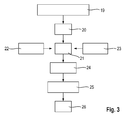
- the paper production method can take place according to the method in Fig. 4 .
- Base products are in turn tobacco by-products like stems, crushed tobacco leaves and tobacco dust 27.
- the raw material is classified in a first step 28.
- classified material is immersed in water 30 and (recycled) extraction means 31.
- a third step 32 ingredients are extracted from the mixture.
- the extraction means laden with extracted substances is recycled 31 and supplied to the second step 29.
- the remaining material is separated into solids 33 and liquids 34.
- the solids are processed into a pulp in a further step 35 during the addition of fibres and fillers 36.
- paper is made in another step 37.
- the liquid 34 separated after the extraction is cleaned in another step 38 and concentrated at a low temperature 39.
- Additives or respectively ingredients 40, 41 are then added in two steps 42, 43. These are for example clove oil and/or another clove product and/or molasses and/or saccharose and/or another sugar product and/or saccharine and/or another artificial sweetener.
- the produced paper 37 is saturated and coated with the liquid that was concentrated and obtained in a second step 44.
- the saturated and coated paper is then dried, cut and air-dried and, if applicable, packed in further steps 45 to 48.
- the reconstituted tobacco 3 produced according to the method described above is cut into shreds in a tobacco-cutting machine.
- a tobacco-cutting machine for example, a KT2-type tobacco-cutting machine from the company Hauni can be used for this, as described in the patent publication EP 0 872 189 A1 .
- the shreds are preferably dried in a tobacco dryer.
- a KLD-type rotary dryer from the company Hauni can be used for this, as described in the patent publication EP 1 929 888 A1 .
- top flavour can be applied to the dried and cut shreds.
- the top flavour can be for example clove oil and/or another clove product and/or molasses and/or saccharose and/or another sugar product and/or saccharine and/or another artificial sweetener.
- a glycerine or another humectant can also be applied.
- a flavouring device can be used for this, for example a flavouring drum with spray application of the type FLT from the company Hauni.
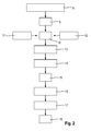
- the tobacco shreds 3 are transported upwards diagonally out of a first reservoir 49 by means of a conveyor 50. From the upper end of the conveyor 50, the tobacco shreds 3 in a veil fall into a guide shaft 51. From the bottom end of the guide shaft 51, the tobacco shreds 3 are dissipated by means of needle and picker roller 52 in a fine veil 53 below a suction tape 54. A negative pressure is supplied to the top side of the suction tape 54. The negative pressure suctions the tobacco shreds 3 on the bottom side of the suction tape 54, where they are shaped into a continuous tobacco rod (or respectively continuous rod of tobacco material) in a channel.
- the tobacco rod 55 is trimmed to a defined height by means of a trimming unit 56 with a trimming disk pair.
- the trimming disks have pockets on the outer periphery. They are synchronized so that alternately a pocket-free section of the outer periphery of both trimming disks separates tobacco from the tobacco rod 55 and the pockets of both trimming disks separate no tobacco from the tobacco rod. A head sealing on the ends of the tobacco rods is hereby prepared.
- the continuously formed tobacco rod 55 is wrapped with cigarette paper in the cigarette machine.
- a continuous strip 58 of cigarette paper is supplied from a cigarette paper loader 57.
- the strip 58 is transported on a garniture tape 59 in the direction of conveyance of the tobacco rod 55 and the tobacco rod 55 is hereby applied to the strip 58.
- the strip 58 is sealed around the tobacco rod 55 after it has been applied.
- cold glue is supplied by means of a glue jet 59.1 in the overlapping area of the two edges of the strip 58.
- the strip 58 is then compressed in the area of the seam in a sealing chamber 60 and the cold glue is hardened by means of a downstream rod heater 61.
- the continuous wrapped tobacco rod 62 exits the rod heater 61.
- a subsequent weight check system 63 with microwave sensor of a system for regulating the weight of the wrapped tobacco rod 62 the weight of the wrapped tobacco rod 62 is measured continuously.
- a subsequent diameter check system 64 of a system for regulating the diameter of the wrapped tobacco rod 62 the weight of the wrapped tobacco rod 62 is measured continuously.
- a rod cutting device 65 from which the continuous wrapped tobacco rod 62 is cut into individual long rod sections 67 by means of rotary knives 66.
- the long rod sections 67 are then deflected perpendicular to the transport direction of the tobacco strand 55 by means of a transfer head 68 into a sequence of parallel long rod sections 67. These are transported on by a pickup drum 69.
- Each long rod section 67 is divided into respectively two rod sections 71 (tobacco rod) by means of a first cut drum 70.
- Each pair of two rod sections 71 is pulled apart by means of a separating drum 72.
- combinations 73 of a long tube 71 are supplied from a second reservoir 78 in the middle, two long filters 75 on both sides and two short tubes 76 on the two ends.
- the combinations 73 are wrapped and held together by a thin paper (e.g. filter paper) 76. They are combined in a filter assembler, which can be part of a cigarette machine (e.g. type "Max" from the company Hauni).
- the production of tube 78 and filters 80 is shown roughly schematically in the upper part of Figure 6 and in Figure 7 .
- the tubes 79 are preferably produced by means of a non-wrap acetate (NWA) filter maker and the filters 80 by means of an acetate filter maker.
- NWA non-wrap acetate
- the tubes 79 and filters 80 are respectively divided into long tubes 74 and long filters 75 and combined in a combiner into a continuous rod, in which long tubes 74 and long filters 75 are arranged alternately.
- the rod is wrapped with the paper 78 and divided into combinations 73 through long tubes 79.
- the combinations 73 are output in succession in parallel alignment from the second hopper 77 and divided respectively into two halves or respectively combinations 82 by means of a second cut drum 81.
- the combinations 82 created by division have respectively in the middle a long filter 75 with two short hollow tubes 76 on both ends.
- a continuous tipping paper web 87 is continuously supplied from a tipping paper loader 86.
- the tipping paper web 87 is provided with a cold glue by means of a tipper gluing device 88, which is heated in a pre-heating device 89.
- the tipping paper web 87 is then cut into short tipping papers 91 by means of a tipping paper cutting drum 90 and the tipping papers 91 are placed around the combinations pushed together on an assembly drum 93 and the adjacent edges of the rod sections 71 by means of a tipping paper drum 92.
- the combinations 94 pre-glued in this manner bypass a rolling drum 95 on a rolling hand heater 96. They are then supplied to a final cut drum 98 by means of a transfer drum 97 and divided into respectively two aerosol-generating articles 1 or respectively two segmented rods through the filter 82.
- the aerosol-generating articles 1 are brought into one row and parallel alignment by means of a turning drum 99 so that the tipping paper 8 is located respectively on the front side in the picture.
- the articles are then supplied to a transfer drum in a laser station 101 by means of a transfer drum 100 and perforations for secondary air are incorporated in the area of the tipping paper 8.
- the articles 1 then make their way onto an inspection drum 103 via a transfer drum 102.
- the quality is checked there and defective articles 1 are sorted out by means of the downstream final reject drum 104.
- the defect-free articles 1 make their way over a transfer drum 105 and a transfer and sampling drum 106 either over an exit drum 107 to a packaging machine or into a sampling box 108.
- the sorted rejects or respectively the intermediate products that have fallen during transport are supplied for further use via a transport conveyor 109.
- the aerosol-generating articles 1 are consumed by means of a heater according to Fig. 8 to 10 .
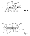
- a heater 110 has a tubular base body 111 with an insertion opening 112 for articles 1 on the one end and an air inlet 113 for air on the other end.
- a capillary tube 114 is arranged concentrically.
- the capillary tube 114 has a needle tip 115.
- the capillary tube 114 and the needle tip 115 are provided respectively with radial holes 116 , which interconnect the inside with the outside of the capillary tube 114 or respectively the needle tip 115.
- the capillary tube 114 On the end lying opposite the needle tip 115, the capillary tube 114 is connected with a funnel-like widening 116.
- the widening 116 is provided with an entry opening 117 for air on the side opposite the capillary tube 114.
- a conduit 118 for air extends from the entry opening 117 through the widening 116 and through the capillary tube 114 up to the needle tip 115.
- a heating element 119 is arranged in the widening 116, for example an electrical resistance heating wire.
- the capillary tube 114 with the needle tip 115 and the widening 116 as well as the heating element 119 are held in the base body 111 by means of holders (not shown).
- the base body 111 has laterally at least one radial ventilation hole 120.
- the electrical heating element 119 is operated with an electrical power supply, for example with a battery or a rechargeable battery.
- An accommodation 121 for a part of an article 1 inside the base body is accessible from outside via the insertion opening 112.
- an article 1 with a rod section 2 is inserted forwards through the insertion opening into the accommodation 121 so that the capillary tube 114 with the needle tip 115 penetrates forwards into the reconstituted tobacco material 3.
- the heating element 119 is heated by means of the electrical power supply.
- air from the air inlet 113 is drawn into the base body 1 through the article 1 and the conduit 118.
- the drawn-in air is heated by the heating element 119 to a temperature around e.g. 375° and makes its way into the rod section 2 through the conduit 118 and the holes 116.
- the heated air there releases an aerosol from the reconstituted tobacco material 3.
- the heated air with the aerosol makes its way to the mouth of the smoker through the tube 5 and the filter 6.
- aerosol and air are cooled down to a temperature of 30° to 40°C and unwanted substances are filtered out of the aerosol.
- secondary air gets into the article through the ventilation hole 120 of the base body 111 and the end of the reconstituted tobacco material 3.
- secondary air is mixed in through secondary-air holes 122 on the filter 6. The secondary air contributes to the cooling down of aerosol and air.
- the smoker can pull out the article 1 and the heater is ready to receive a new article 1.
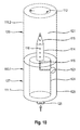
- the heater 110.1 in Fig. 10 differs from the one previously described in particular in that a vacuum sensor 123 is connected to the conduit 118.
- the vacuum sensor 123 is connected with an electronic controller 124.
- the heater 110.1 has a sound generator 125 for generating a cracking sound.
- An electrical power supply is connected with the controller and the heater.
- the electrical power supply is optionally connectible via a plug connection 126, for example via a USB port.
- the electrical power supply can also be obtained from a computer, laptop, etc.
- the heater 110.1 according to Fig. 10 can be made of several modules 127.
- a module 127 comprises in a part 111.1 of the cylindrical base body 111 the capillary tube 114 with the needle tip 115, the sensor 123, the controller 124, the sound generator 125 and the heating element 119.
- the further module 128 consists of a further part 111.2 of the cylindrical base body, provided if applicable with secondary-air holes.
- the inner diameter of the further module is adjusted to the diameter of the article 1.
- the heater 110.1 can be produced with modules 128 with different diameters in order to use articles 1 with a different outer diameter.
- the heater 110.1 can have a power supply module, which can be connected with the other end of the module 127, e.g. through adhering or by means of a detachable connection, such as a screw connection.
- the power supply module can also have a part of the cylindrical base body 111, in which batteries or rechargeable batteries are arranged, e.g. button cells.
- the connection of the power supply module with the electrical components of the module 127 can take place via plug connections or fixed wiring.
- the sensor 123 registers a negative pressure and the controller 124 controls a crackle sound as is typical when smoking Indonesian cigarettes through the burning of clove products.
- the controller can switch on the heating element 119 during drawing on the cigarette or supply increased power to the heating element 119 in order to heat up the drawn-in air during inhalation.
- Fig. 11 and 12 show a device for cleaning a suction tape 129, which can be used in particular on a suction tape 54 according to Fig. 1 .
- the device 129 comprises at least one water pressure nozzle 130, which is pointed at the underside of the tape 54. Furthermore, it comprises an air pressure nozzle 131, which is pointed at the underside of the tape 54 in the direction of flow of the tape 54 behind the water pressure nozzle 130. Furthermore, it comprises a supply (feed) device for ambient air 132, which is pointed at the underside of the tape 54 in the direction of flow of the tape 54 behind the air pressure nozzle.
- water pressure nozzles 130 with a diameter of 0.1 to 1 mm are used, which are operated with a water pressure of max. 100 bar.
- water pressure nozzles 130 are used.
- the water pressure nozzles 130 are preferably flat spray nozzles.
- flat spray nozzles with the trade name Delavan CAC are used.
- the air pressure nozzles 131 preferably have a diameter of 0.1 to 1 mm.
- air pressure nozzles 131 are preferably used.
- the air pressure nozzles 131 can be arranged horizontally, vertically and diagonally with respect to the plane, through which the tape passes on the air pressure nozzles 131.
- an exhaust hood 133 is arranged opposite the water pressure nozzle 129, the air pressure nozzle 130 and the supply device for ambient air 132.
- the air pressure nozzle 129 is connected with a water pressure pump 135 via a water pressure regulator 134, the water pressure pump 135 being supplied with water out of a container 136.
- the water pressure pump 135 can build up a water pressure of 2 to 250 bar.
- the water pressure regulator 134 enables a regulation of the water pressure in the range of 5 to 250 bar.
- the air pressure nozzle 130 is connected with a compressed air network 138 via an air pressure regulator 137.
- the air pressure can be adjusted by means of the air pressure regulator 137 in the range of 0.1 to 10 bar.
- the supply device for ambient air 132 is for example a hood opened towards the underside of the tape 54, which is connected with ambient air via a conduit.
- the exhaust hood 133 is connected with a two-way valve 140 via a conduit 139.
- the two-way valve 139 is connected on one side with a dust fan 141 and on the other side via series-connected filters 142 and 143 with a vacuum pump 144 or other vacuum source.
- the vacuum source 144 generates a negative pressure of 100 to 500 mbar with respect to the ambient temperature.
- the filter 142 serves to remove water and dirty tobacco. It is connected to a water tank 145 via a discharge.
- the cleaning device 129 is arranged within a suction chamber 146 for creating a negative pressure on the top side of the tape 54.
- the cleaning of the tape 54 is preferably performed intermittently. It preferably takes place after the production of 50,000 to 1,000,000 cigarettes or respectively a time frame, which corresponds with a production of 50,000 to 100,000 cigarettes.
- the service life of the tape 54 can be prolonged considerably.
- the minimum service life of the tape 54 is 522,000 cigarettes when using the cleaning device 129, and the maximum achieved runtime is 2,323,000 cigarettes.
- 1,474,225 cigarettes were able to be produced with a tape 54, which was cleaned regularly by means of the cleaning device 129.
Priority Applications (1)
| Application Number | Priority Date | Filing Date | Title |
|---|---|---|---|
| EP15169472.6A EP3075268B1 (de) | 2015-04-02 | 2015-05-27 | Vorrichtung zum herstellen eines endlosen strangs aus klebrigem tabakmaterial |
Applications Claiming Priority (2)
| Application Number | Priority Date | Filing Date | Title |
|---|---|---|---|
| EP15162513.4A EP3075266A1 (de) | 2015-04-02 | 2015-04-02 | Verfahren zur herstellung eines aerosolbildenden artikels mit rekonstituiertem tabakmaterial, aerosolbildender artikel mit dem rekonstituierten tabakmaterial und verwendung eines aerosolbildenden artikels mit rekonstituiertem tabakmaterial |
| EP15169472.6A EP3075268B1 (de) | 2015-04-02 | 2015-05-27 | Vorrichtung zum herstellen eines endlosen strangs aus klebrigem tabakmaterial |
Publications (2)
| Publication Number | Publication Date |
|---|---|
| EP3075268A1 true EP3075268A1 (de) | 2016-10-05 |
| EP3075268B1 EP3075268B1 (de) | 2020-01-01 |
Family
ID=52811045
Family Applications (4)
| Application Number | Title | Priority Date | Filing Date |
|---|---|---|---|
| EP15162513.4A Withdrawn EP3075266A1 (de) | 2015-04-02 | 2015-04-02 | Verfahren zur herstellung eines aerosolbildenden artikels mit rekonstituiertem tabakmaterial, aerosolbildender artikel mit dem rekonstituierten tabakmaterial und verwendung eines aerosolbildenden artikels mit rekonstituiertem tabakmaterial |
| EP15169385.0A Withdrawn EP3075272A3 (de) | 2015-04-02 | 2015-05-27 | Heizung für tabakmaterialhaltige stangen und system aus einer heizung für tabakmaterialhaltige stangen |
| EP15169472.6A Active EP3075268B1 (de) | 2015-04-02 | 2015-05-27 | Vorrichtung zum herstellen eines endlosen strangs aus klebrigem tabakmaterial |
| EP15169475.9A Withdrawn EP3075269A3 (de) | 2015-04-02 | 2015-05-27 | Segmentierte stange zur erzeugung von aerosolen und verfahren zur herstellung einer segmentierten stange zur erzeugung von aerosolen |
Family Applications Before (2)
| Application Number | Title | Priority Date | Filing Date |
|---|---|---|---|
| EP15162513.4A Withdrawn EP3075266A1 (de) | 2015-04-02 | 2015-04-02 | Verfahren zur herstellung eines aerosolbildenden artikels mit rekonstituiertem tabakmaterial, aerosolbildender artikel mit dem rekonstituierten tabakmaterial und verwendung eines aerosolbildenden artikels mit rekonstituiertem tabakmaterial |
| EP15169385.0A Withdrawn EP3075272A3 (de) | 2015-04-02 | 2015-05-27 | Heizung für tabakmaterialhaltige stangen und system aus einer heizung für tabakmaterialhaltige stangen |
Family Applications After (1)
| Application Number | Title | Priority Date | Filing Date |
|---|---|---|---|
| EP15169475.9A Withdrawn EP3075269A3 (de) | 2015-04-02 | 2015-05-27 | Segmentierte stange zur erzeugung von aerosolen und verfahren zur herstellung einer segmentierten stange zur erzeugung von aerosolen |
Country Status (3)
| Country | Link |
|---|---|
| EP (4) | EP3075266A1 (de) |
| JP (1) | JP6272280B2 (de) |
| CN (1) | CN106036983A (de) |
Families Citing this family (47)
| Publication number | Priority date | Publication date | Assignee | Title |
|---|---|---|---|---|
| CN108061673B (zh) * | 2016-11-07 | 2021-02-02 | 湖南中烟工业有限责任公司 | 一种电子烟雾化气溶胶取样装置和测试装置及测试方法 |
| EA038903B1 (ru) | 2016-12-30 | 2021-11-08 | Джт Интернэшнл С.А. | Аппарат для генерирования аэрозоля, система для генерирования аэрозоля и способ генерирования аэрозоля |
| CN106551420A (zh) * | 2017-01-23 | 2017-04-05 | 江苏中烟工业有限责任公司 | 一种应用烟梗制备电子烟烟液的方法 |
| CN106858697A (zh) * | 2017-03-01 | 2017-06-20 | 昆明旭邦机械有限公司 | 一种微波膨胀梗丝加香装置 |
| GB201705693D0 (en) * | 2017-04-07 | 2017-05-24 | Sensus Invest Ltd | Carrier, apparatus and method |
| GB201705888D0 (en) * | 2017-04-12 | 2017-05-24 | British American Tobacco Investments Ltd | Apparatus for volatilising smokable material and a smoking article |
| JP3212228U (ja) * | 2017-06-16 | 2017-08-31 | 株式会社 東亜産業 | タバコ植物または非タバコ植物を用いた電子タバコカートリッジおよびその支持部材 |
| KR20200052268A (ko) * | 2017-09-07 | 2020-05-14 | 필립모리스 프로덕츠 에스.에이. | 상이한 기재와 함께 사용하기 위한 에어로졸 발생 장치, 및 관련 사용자 인터페이스 및 방법 |
| CN107568801A (zh) * | 2017-09-30 | 2018-01-12 | 四川三联新材料有限公司 | 一种发烟制品及其制造方法 |
| CN107536116B (zh) * | 2017-09-30 | 2024-03-29 | 四川三联新材料有限公司 | 一种发烟加热器以及发烟制品 |
| DE102017126543A1 (de) * | 2017-11-13 | 2019-05-16 | Hauni Maschinenbau Gmbh | Verfahren und Vorrichtung zur Herstellung von Heat Sticks |
| GB201718923D0 (en) * | 2017-11-16 | 2018-01-03 | British American Tobacco Investments Ltd | Consumable ventilation control |
| CN109984369A (zh) * | 2017-12-29 | 2019-07-09 | 上海新型烟草制品研究院有限公司 | 一种口含烟粉末制备生产线 |
| JP6861998B2 (ja) * | 2018-01-09 | 2021-04-21 | 株式会社東亜産業 | 電子タバコカートリッジ及び電子タバコカートリッジ用充填物 |
| DE102018103635A1 (de) * | 2018-02-19 | 2019-08-22 | Hauni Maschinenbau Gmbh | Multisegmentproduktherstellung der Tabak verarbeitenden Industrie |
| CN112888322B (zh) * | 2018-09-17 | 2023-03-28 | Comas-建设专用机股份公司 | 用于生产再造烟草的方法和设备 |
| CN109123806A (zh) * | 2018-09-21 | 2019-01-04 | 深圳麦克韦尔股份有限公司 | 烘烤烟具 |
| CN112804890B (zh) * | 2018-10-05 | 2022-08-30 | 日本烟草产业株式会社 | 吸烟物品的制造方法 |
| JP6589084B1 (ja) * | 2018-10-05 | 2019-10-09 | 日本たばこ産業株式会社 | 加熱式喫煙物品の製造方法 |
| CA3111358A1 (en) * | 2018-10-08 | 2020-04-16 | Philip Morris Products S.A. | Novel clove-containing aerosol-generating substrate |
| GB201817557D0 (en) | 2018-10-29 | 2018-12-12 | Nerudia Ltd | Smoking substitute consumable |
| EP3886621A1 (de) * | 2018-11-29 | 2021-10-06 | JT International SA | Aerosolerzeugungsartikel und verfahren zur herstellung eines aerosolerzeugungsartikels |
| KR102281867B1 (ko) | 2018-12-05 | 2021-07-26 | 주식회사 케이티앤지 | 에어로졸 생성 물품 및 이와 함께 이용되는 에어로졸 생성 장치 |
| WO2020115151A1 (en) * | 2018-12-06 | 2020-06-11 | Philip Morris Products S.A. | Aerosol-generating article with high aerosol former content |
| DE102019100112B4 (de) * | 2019-01-04 | 2020-09-10 | Delfortgroup Ag | Biologisch abbaubares Segment eines Rauchartikels |
| BR112021011385A2 (pt) * | 2019-01-14 | 2021-08-31 | Philip Morris Products S.A. | Sistema gerador de aerossol aquecido por radiação, cartucho, elemento gerador de aerossol e método para os mesmos |
| WO2020148213A1 (en) * | 2019-01-14 | 2020-07-23 | Philip Morris Products S.A. | Infrared heated aerosol-generating element |
| GB201903284D0 (en) * | 2019-03-11 | 2019-04-24 | Nicoventures Trading Ltd | An article for use in a non-combustible aerosol provision system |
| JP7150977B2 (ja) * | 2019-03-29 | 2022-10-11 | 日本たばこ産業株式会社 | 冷却セグメント、非燃焼加熱型香味吸引物品、非燃焼加熱型香味吸引物品の使用方法及び非燃焼加熱型香味吸引システム |
| JP2022526103A (ja) * | 2019-04-04 | 2022-05-23 | フィリップ・モーリス・プロダクツ・ソシエテ・アノニム | 中空管状支持要素を備えるエアロゾル発生物品 |
| KR102253047B1 (ko) * | 2019-05-08 | 2021-05-17 | 주식회사 케이티앤지 | 에어로졸 생성 장치 및 에어로졸 생성 시스템 |
| KR102217756B1 (ko) * | 2019-08-20 | 2021-02-18 | 주식회사 케이티앤지 | 다중 매질부를 포함하는 흡연물품 |
| EP4042889A4 (de) * | 2019-10-10 | 2023-06-21 | Japan Tobacco Inc. | Aromainhalator mit verbrennungsfreier aufheizung |
| JP7350870B2 (ja) * | 2019-10-10 | 2023-09-26 | 日本たばこ産業株式会社 | 非燃焼加熱型香味吸引器具 |
| CN110584219A (zh) * | 2019-10-15 | 2019-12-20 | 中国科学技术大学先进技术研究院 | 燃料流量调节装置和加热不燃烧型烟草制品 |
| KR20210073373A (ko) * | 2019-12-10 | 2021-06-18 | 주식회사 케이티앤지 | 담배 시트를 포함하는 에어로졸 발생 물품, 및 이를 이용한 에어로졸 발생 시스템 |
| GB201919104D0 (en) * | 2019-12-20 | 2020-02-05 | Nicoventures Trading Ltd | An article for use in a non-combustible aerosol provision system |
| KR102458970B1 (ko) * | 2020-05-19 | 2022-10-24 | 주식회사 케이티앤지 | 소리가 발생되는 흡연 물품 |
| GB202009163D0 (en) * | 2020-06-16 | 2020-07-29 | Nicoventures Trading Ltd | Article for use in non-combustible aerosol provision system |
| CN112716031B (zh) * | 2021-01-08 | 2022-11-18 | 江西中烟工业有限责任公司 | 一种颗粒型气溶胶生成制品及其卷接成型方法 |
| CN112916390A (zh) * | 2021-04-19 | 2021-06-08 | 湖南中南高创烟草科技有限公司 | 一种新型除梗装置 |
| IT202100010538A1 (it) * | 2021-04-27 | 2022-10-27 | Sasib Spa | Metodo di confezionamento e macchina confezionatrice per la produzione di articoli da fumo senza combustione |
| WO2022233827A1 (en) * | 2021-05-05 | 2022-11-10 | Jt International Sa | Aerosol-generating article with a capacitively coupled rfid tag |
| CN113243547B (zh) * | 2021-05-11 | 2022-09-13 | 河北白沙烟草有限责任公司 | 一种烟丝加香滚筒自动调速方法及系统 |
| GB202108806D0 (en) * | 2021-06-18 | 2021-08-04 | Nicoventures Trading Ltd | Aerosol provision device |
| CN113475737A (zh) * | 2021-06-29 | 2021-10-08 | 河南中烟工业有限责任公司 | 一种烟梗加工方法及卷烟 |
| EP4252555A1 (de) * | 2022-03-30 | 2023-10-04 | JT International SA | E-vaping-gerät-aerosol erzeugender wärmestab |
Citations (20)
| Publication number | Priority date | Publication date | Assignee | Title |
|---|---|---|---|---|
| US3817258A (en) * | 1971-11-11 | 1974-06-18 | Svenska Tobaks Ab | Method of producing cigarettes or the like filled with tobacco containing one or more aromatic liquid agents, and a device for carrying out the method |
| US4729468A (en) * | 1985-04-26 | 1988-03-08 | Korber Ag | Apparatus for monitoring the condition of filamentary belts in cigarette making machines and the like |
| EP0872189A1 (de) | 1997-04-17 | 1998-10-21 | Universelle Engineering U.N.I. GmbH | Tabakschneider |
| US6135267A (en) * | 1997-01-23 | 2000-10-24 | Voith Sulzer Papiermaschinen Gmbh | Device for cleaning a transport belt |
| EP0846424B1 (de) | 1996-12-03 | 2002-03-27 | Philip Morris Products S.A. | Vorrichtung zum Vor-Egalisieren eines Tabakstromes |
| US7234586B1 (en) * | 1999-08-17 | 2007-06-26 | Paul Bernard Newman | Self-cleaning foodstuff conveyors |
| EP1929888A1 (de) | 2006-12-07 | 2008-06-11 | Hauni Maschinenbau AG | Trommeltrockner der Tabak verarbeitenden Industrie |
| WO2011076407A1 (en) | 2009-12-23 | 2011-06-30 | Philip Morris Products S.A. | An elongate heater for an electrically heated aerosol-generating system |
| EP2443947A1 (de) | 2009-06-18 | 2012-04-25 | Japan Tobacco, Inc. | Brennfreier rauchartikel mit kohlenstoffhaltiger wärmequelle |
| EP1993388B1 (de) | 2006-03-16 | 2012-08-15 | R.J.Reynolds Tobacco Company | Rauchartikel |
| US8430106B2 (en) | 2006-08-03 | 2013-04-30 | British American Tobacco (Investments) Limited | Volatilization device |
| WO2013098395A1 (en) | 2011-12-30 | 2013-07-04 | Philip Morris Products S.A. | Aerosol generating device with improved temperature distribution |
| WO2013098409A1 (en) | 2011-12-30 | 2013-07-04 | Philip Morris Products S.A. | Smoking article with front-plug and aerosol-forming substrate and method |
| WO2013098410A2 (en) | 2011-12-30 | 2013-07-04 | Philip Morris Products S.A. | Smoking article with front-plug and method |
| WO2013098405A2 (en) | 2011-12-30 | 2013-07-04 | Philip Morris Products S.A. | Aerosol-generating article for use with an aerosol-generating device |
| WO2013178767A1 (en) | 2012-05-31 | 2013-12-05 | Philip Morris Products S.A. | Flavoured rods for use in aerosol-generating articles |
| WO2013178768A1 (en) | 2012-05-31 | 2013-12-05 | Philip Morris Products S.A. | Thermally conducting rods for use in aerosol-generating articles |
| WO2013178766A1 (en) | 2012-05-31 | 2013-12-05 | Philip Morris Products S.A. | Blended rods for use in aerosol-generating articles |
| WO2013190036A1 (en) | 2012-06-21 | 2013-12-27 | Philip Morris Products S.A. | Smoking article for use with an internal heating element |
| WO2014048745A1 (en) | 2012-09-25 | 2014-04-03 | British American Tobacco (Investments) Limited | Heating smokable material |
Family Cites Families (17)
| Publication number | Priority date | Publication date | Assignee | Title |
|---|---|---|---|---|
| DE2135637C3 (de) * | 1971-07-16 | 1980-05-29 | Hauni-Werke Koerber & Co Kg, 2050 Hamburg | Verfahren und Vorrichtung zum Zusetzen einer Beimischung zu Tabak |
| US4141369A (en) * | 1977-01-24 | 1979-02-27 | Burruss Robert P | Noncombustion system for the utilization of tobacco and other smoking materials |
| US4899765A (en) * | 1988-07-19 | 1990-02-13 | R. J. Reynolds Tobacco Company | Process for manufacturing cigarette rods |
| CA2527939C (en) * | 1992-03-25 | 2008-07-15 | Japan Tobacco Inc. | Apparatus for manufacturing components for smoking articles |
| US5377698A (en) * | 1993-04-30 | 1995-01-03 | Brown & Williamson Tobacco Corporation | Reconstituted tobacco product |
| JP4322936B2 (ja) * | 1995-04-20 | 2009-09-02 | フィリップ・モーリス・プロダクツ・インコーポレイテッド | 喫煙装置に使用するためのヒータ |
| AR002035A1 (es) * | 1995-04-20 | 1998-01-07 | Philip Morris Prod | Un cigarrillo, un cigarrillo y encendedor adaptados para cooperar entre si, un metodo para mejorar la entrega de aerosol de un cigarrillo, un material continuo de tabaco, un cigarrillo operativo, un metodo para manufacturar un material continuo, el material asi obtenido, un calentador, un metodo para formar un calentador y un sistema electrico para fumar |
| US6089857A (en) * | 1996-06-21 | 2000-07-18 | Japan Tobacco, Inc. | Heater for generating flavor and flavor generation appliance |
| CN1230104C (zh) * | 2000-07-12 | 2005-12-07 | 菲利浦莫里斯生产公司 | 隐藏式过滤嘴和含有一个隐藏式过滤嘴的可抽吸的物品 |
| US6615840B1 (en) * | 2002-02-15 | 2003-09-09 | Philip Morris Incorporated | Electrical smoking system and method |
| UA91206C2 (uk) * | 2004-12-15 | 2010-07-12 | Джапан Тобакко Інк. | Пристрій для виготовлення стрижнеподібних курильних виробів |
| DE102005034169B4 (de) * | 2005-07-21 | 2008-05-29 | NjoyNic Ltd., Glen Parva | Rauchfreie Zigarette |
| US7856988B2 (en) * | 2005-10-18 | 2010-12-28 | Philip Morris Usa Inc. | Method of making reconstituted tobacco with bonded flavorant |
| TWI532442B (zh) * | 2007-03-09 | 2016-05-11 | 菲利浦莫里斯製品股份有限公司 | 製造重組煙草薄片之方法 |
| RU2360583C1 (ru) * | 2008-04-28 | 2009-07-10 | Владимир Николаевич Урцев | Трубка для бездымного курения |
| GB2473264A (en) * | 2009-09-08 | 2011-03-09 | British American Tobacco Co | Volatilization Device |
| HUE034732T2 (en) * | 2012-04-30 | 2018-02-28 | Philip Morris Products Sa | Two-part multi-component interface |
-
2015
- 2015-04-02 EP EP15162513.4A patent/EP3075266A1/de not_active Withdrawn
- 2015-05-27 EP EP15169385.0A patent/EP3075272A3/de not_active Withdrawn
- 2015-05-27 EP EP15169472.6A patent/EP3075268B1/de active Active
- 2015-05-27 EP EP15169475.9A patent/EP3075269A3/de not_active Withdrawn
- 2015-08-28 JP JP2015169710A patent/JP6272280B2/ja not_active Expired - Fee Related
- 2015-10-20 CN CN201510681194.0A patent/CN106036983A/zh active Pending
Patent Citations (20)
| Publication number | Priority date | Publication date | Assignee | Title |
|---|---|---|---|---|
| US3817258A (en) * | 1971-11-11 | 1974-06-18 | Svenska Tobaks Ab | Method of producing cigarettes or the like filled with tobacco containing one or more aromatic liquid agents, and a device for carrying out the method |
| US4729468A (en) * | 1985-04-26 | 1988-03-08 | Korber Ag | Apparatus for monitoring the condition of filamentary belts in cigarette making machines and the like |
| EP0846424B1 (de) | 1996-12-03 | 2002-03-27 | Philip Morris Products S.A. | Vorrichtung zum Vor-Egalisieren eines Tabakstromes |
| US6135267A (en) * | 1997-01-23 | 2000-10-24 | Voith Sulzer Papiermaschinen Gmbh | Device for cleaning a transport belt |
| EP0872189A1 (de) | 1997-04-17 | 1998-10-21 | Universelle Engineering U.N.I. GmbH | Tabakschneider |
| US7234586B1 (en) * | 1999-08-17 | 2007-06-26 | Paul Bernard Newman | Self-cleaning foodstuff conveyors |
| EP1993388B1 (de) | 2006-03-16 | 2012-08-15 | R.J.Reynolds Tobacco Company | Rauchartikel |
| US8430106B2 (en) | 2006-08-03 | 2013-04-30 | British American Tobacco (Investments) Limited | Volatilization device |
| EP1929888A1 (de) | 2006-12-07 | 2008-06-11 | Hauni Maschinenbau AG | Trommeltrockner der Tabak verarbeitenden Industrie |
| EP2443947A1 (de) | 2009-06-18 | 2012-04-25 | Japan Tobacco, Inc. | Brennfreier rauchartikel mit kohlenstoffhaltiger wärmequelle |
| WO2011076407A1 (en) | 2009-12-23 | 2011-06-30 | Philip Morris Products S.A. | An elongate heater for an electrically heated aerosol-generating system |
| WO2013098395A1 (en) | 2011-12-30 | 2013-07-04 | Philip Morris Products S.A. | Aerosol generating device with improved temperature distribution |
| WO2013098409A1 (en) | 2011-12-30 | 2013-07-04 | Philip Morris Products S.A. | Smoking article with front-plug and aerosol-forming substrate and method |
| WO2013098410A2 (en) | 2011-12-30 | 2013-07-04 | Philip Morris Products S.A. | Smoking article with front-plug and method |
| WO2013098405A2 (en) | 2011-12-30 | 2013-07-04 | Philip Morris Products S.A. | Aerosol-generating article for use with an aerosol-generating device |
| WO2013178767A1 (en) | 2012-05-31 | 2013-12-05 | Philip Morris Products S.A. | Flavoured rods for use in aerosol-generating articles |
| WO2013178768A1 (en) | 2012-05-31 | 2013-12-05 | Philip Morris Products S.A. | Thermally conducting rods for use in aerosol-generating articles |
| WO2013178766A1 (en) | 2012-05-31 | 2013-12-05 | Philip Morris Products S.A. | Blended rods for use in aerosol-generating articles |
| WO2013190036A1 (en) | 2012-06-21 | 2013-12-27 | Philip Morris Products S.A. | Smoking article for use with an internal heating element |
| WO2014048745A1 (en) | 2012-09-25 | 2014-04-03 | British American Tobacco (Investments) Limited | Heating smokable material |
Non-Patent Citations (2)
| Title |
|---|
| "Chemical and Biological Studies on New Cigarette Prototypes that Heat Instead of Burn Tobacco", R.J. REYNOLDS TOBACCO COMPANY MONOGRAPH, 1988 |
| INHALATION TOXICOLOGY, vol. 12, no. 5, 2000, pages 1 - 58 |
Also Published As
| Publication number | Publication date |
|---|---|
| EP3075268B1 (de) | 2020-01-01 |
| EP3075266A1 (de) | 2016-10-05 |
| JP6272280B2 (ja) | 2018-01-31 |
| CN106036983A (zh) | 2016-10-26 |
| EP3075272A3 (de) | 2017-02-15 |
| JP2016195585A (ja) | 2016-11-24 |
| EP3075269A3 (de) | 2017-02-15 |
| EP3075272A2 (de) | 2016-10-05 |
| EP3075269A2 (de) | 2016-10-05 |
Similar Documents
| Publication | Publication Date | Title |
|---|---|---|
| EP3075268A1 (de) | Vorrichtung zum herstellen eines endlosen strangs aus klebrigem tabakmaterial | |
| RU2632277C2 (ru) | Теплопроводящие стержни для использования в аэрозоль-генерирующих изделиях | |
| EP2854570B1 (de) | Aromatisierte stäbe zur verwendung in aerosolerzeugungsartikeln | |
| RU2628987C2 (ru) | Смешанные стержни для использования в аэрозоль-генерирующих изделиях | |
| HUE028340T2 (en) | Electrically operated aerosol generating system | |
| CN114729511B (zh) | 具有双重纸包装物的气溶胶生成基质元件 | |
| US20240065313A1 (en) | Articles for use in non-combustible aerosol provision systems | |
| KR102356641B1 (ko) | 에어로졸 형성 로드 제조 방법 및 장치 | |
| CN113645858A (zh) | 加热式香烟、加热式香烟制品、加热式香烟中的烟杆的制造方法以及制造装置 | |
| TWI832918B (zh) | 吸煙替代品耗材、用於製造加熱不燃燒(hnb)耗材的方法、hnb耗材、包括hnb耗材的系統、及使用該系統的方法 | |
| WO2023118857A2 (en) | Apparatus for manufacturing a rod of aerosol generating material, methods of manufacturing a rod of aerosol generating material and methods of manufacturing an article for an aerosol provision system | |
| KR20240055792A (ko) | 물질 회수 장치 | |
| CN116801737A (zh) | 新颖的气溶胶生成基质 | |
| WO2023052791A1 (en) | A substance recovery apparatus |
Legal Events
| Date | Code | Title | Description |
|---|---|---|---|
| PUAI | Public reference made under article 153(3) epc to a published international application that has entered the european phase |
Free format text: ORIGINAL CODE: 0009012 |
|
| AK | Designated contracting states |
Kind code of ref document: A1 Designated state(s): AL AT BE BG CH CY CZ DE DK EE ES FI FR GB GR HR HU IE IS IT LI LT LU LV MC MK MT NL NO PL PT RO RS SE SI SK SM TR |
|
| AX | Request for extension of the european patent |
Extension state: BA ME |
|
| STAA | Information on the status of an ep patent application or granted ep patent |
Free format text: STATUS: REQUEST FOR EXAMINATION WAS MADE |
|
| 17P | Request for examination filed |
Effective date: 20170324 |
|
| RBV | Designated contracting states (corrected) |
Designated state(s): AL AT BE BG CH CY CZ DE DK EE ES FI FR GB GR HR HU IE IS IT LI LT LU LV MC MK MT NL NO PL PT RO RS SE SI SK SM TR |
|
| STAA | Information on the status of an ep patent application or granted ep patent |
Free format text: STATUS: EXAMINATION IS IN PROGRESS |
|
| 17Q | First examination report despatched |
Effective date: 20180730 |
|
| GRAP | Despatch of communication of intention to grant a patent |
Free format text: ORIGINAL CODE: EPIDOSNIGR1 |
|
| STAA | Information on the status of an ep patent application or granted ep patent |
Free format text: STATUS: GRANT OF PATENT IS INTENDED |
|
| RIC1 | Information provided on ipc code assigned before grant |
Ipc: A24F 47/00 20060101ALI20190701BHEP Ipc: A24C 5/18 20060101AFI20190701BHEP Ipc: A24C 5/47 20060101ALN20190701BHEP Ipc: A24D 1/00 20060101ALI20190701BHEP Ipc: A24B 15/12 20060101ALI20190701BHEP |
|
| INTG | Intention to grant announced |
Effective date: 20190725 |
|
| GRAS | Grant fee paid |
Free format text: ORIGINAL CODE: EPIDOSNIGR3 |
|
| GRAA | (expected) grant |
Free format text: ORIGINAL CODE: 0009210 |
|
| STAA | Information on the status of an ep patent application or granted ep patent |
Free format text: STATUS: THE PATENT HAS BEEN GRANTED |
|
| AK | Designated contracting states |
Kind code of ref document: B1 Designated state(s): AL AT BE BG CH CY CZ DE DK EE ES FI FR GB GR HR HU IE IS IT LI LT LU LV MC MK MT NL NO PL PT RO RS SE SI SK SM TR |
|
| REG | Reference to a national code |
Ref country code: GB Ref legal event code: FG4D |
|
| REG | Reference to a national code |
Ref country code: CH Ref legal event code: EP Ref country code: AT Ref legal event code: REF Ref document number: 1218664 Country of ref document: AT Kind code of ref document: T Effective date: 20200115 |
|
| REG | Reference to a national code |
Ref country code: DE Ref legal event code: R096 Ref document number: 602015044525 Country of ref document: DE |
|
| REG | Reference to a national code |
Ref country code: IE Ref legal event code: FG4D |
|
| REG | Reference to a national code |
Ref country code: NL Ref legal event code: MP Effective date: 20200101 |
|
| REG | Reference to a national code |
Ref country code: LT Ref legal event code: MG4D |
|
| PG25 | Lapsed in a contracting state [announced via postgrant information from national office to epo] |
Ref country code: CZ Free format text: LAPSE BECAUSE OF FAILURE TO SUBMIT A TRANSLATION OF THE DESCRIPTION OR TO PAY THE FEE WITHIN THE PRESCRIBED TIME-LIMIT Effective date: 20200101 Ref country code: PT Free format text: LAPSE BECAUSE OF FAILURE TO SUBMIT A TRANSLATION OF THE DESCRIPTION OR TO PAY THE FEE WITHIN THE PRESCRIBED TIME-LIMIT Effective date: 20200527 Ref country code: NO Free format text: LAPSE BECAUSE OF FAILURE TO SUBMIT A TRANSLATION OF THE DESCRIPTION OR TO PAY THE FEE WITHIN THE PRESCRIBED TIME-LIMIT Effective date: 20200401 Ref country code: FI Free format text: LAPSE BECAUSE OF FAILURE TO SUBMIT A TRANSLATION OF THE DESCRIPTION OR TO PAY THE FEE WITHIN THE PRESCRIBED TIME-LIMIT Effective date: 20200101 Ref country code: RS Free format text: LAPSE BECAUSE OF FAILURE TO SUBMIT A TRANSLATION OF THE DESCRIPTION OR TO PAY THE FEE WITHIN THE PRESCRIBED TIME-LIMIT Effective date: 20200101 Ref country code: NL Free format text: LAPSE BECAUSE OF FAILURE TO SUBMIT A TRANSLATION OF THE DESCRIPTION OR TO PAY THE FEE WITHIN THE PRESCRIBED TIME-LIMIT Effective date: 20200101 Ref country code: LT Free format text: LAPSE BECAUSE OF FAILURE TO SUBMIT A TRANSLATION OF THE DESCRIPTION OR TO PAY THE FEE WITHIN THE PRESCRIBED TIME-LIMIT Effective date: 20200101 |
|
| PG25 | Lapsed in a contracting state [announced via postgrant information from national office to epo] |
Ref country code: BG Free format text: LAPSE BECAUSE OF FAILURE TO SUBMIT A TRANSLATION OF THE DESCRIPTION OR TO PAY THE FEE WITHIN THE PRESCRIBED TIME-LIMIT Effective date: 20200401 Ref country code: GR Free format text: LAPSE BECAUSE OF FAILURE TO SUBMIT A TRANSLATION OF THE DESCRIPTION OR TO PAY THE FEE WITHIN THE PRESCRIBED TIME-LIMIT Effective date: 20200402 Ref country code: SE Free format text: LAPSE BECAUSE OF FAILURE TO SUBMIT A TRANSLATION OF THE DESCRIPTION OR TO PAY THE FEE WITHIN THE PRESCRIBED TIME-LIMIT Effective date: 20200101 Ref country code: IS Free format text: LAPSE BECAUSE OF FAILURE TO SUBMIT A TRANSLATION OF THE DESCRIPTION OR TO PAY THE FEE WITHIN THE PRESCRIBED TIME-LIMIT Effective date: 20200501 Ref country code: LV Free format text: LAPSE BECAUSE OF FAILURE TO SUBMIT A TRANSLATION OF THE DESCRIPTION OR TO PAY THE FEE WITHIN THE PRESCRIBED TIME-LIMIT Effective date: 20200101 Ref country code: HR Free format text: LAPSE BECAUSE OF FAILURE TO SUBMIT A TRANSLATION OF THE DESCRIPTION OR TO PAY THE FEE WITHIN THE PRESCRIBED TIME-LIMIT Effective date: 20200101 |
|
| REG | Reference to a national code |
Ref country code: DE Ref legal event code: R097 Ref document number: 602015044525 Country of ref document: DE |
|
| PG25 | Lapsed in a contracting state [announced via postgrant information from national office to epo] |
Ref country code: ES Free format text: LAPSE BECAUSE OF FAILURE TO SUBMIT A TRANSLATION OF THE DESCRIPTION OR TO PAY THE FEE WITHIN THE PRESCRIBED TIME-LIMIT Effective date: 20200101 Ref country code: SK Free format text: LAPSE BECAUSE OF FAILURE TO SUBMIT A TRANSLATION OF THE DESCRIPTION OR TO PAY THE FEE WITHIN THE PRESCRIBED TIME-LIMIT Effective date: 20200101 Ref country code: RO Free format text: LAPSE BECAUSE OF FAILURE TO SUBMIT A TRANSLATION OF THE DESCRIPTION OR TO PAY THE FEE WITHIN THE PRESCRIBED TIME-LIMIT Effective date: 20200101 Ref country code: EE Free format text: LAPSE BECAUSE OF FAILURE TO SUBMIT A TRANSLATION OF THE DESCRIPTION OR TO PAY THE FEE WITHIN THE PRESCRIBED TIME-LIMIT Effective date: 20200101 Ref country code: DK Free format text: LAPSE BECAUSE OF FAILURE TO SUBMIT A TRANSLATION OF THE DESCRIPTION OR TO PAY THE FEE WITHIN THE PRESCRIBED TIME-LIMIT Effective date: 20200101 Ref country code: SM Free format text: LAPSE BECAUSE OF FAILURE TO SUBMIT A TRANSLATION OF THE DESCRIPTION OR TO PAY THE FEE WITHIN THE PRESCRIBED TIME-LIMIT Effective date: 20200101 |
|
| PLBE | No opposition filed within time limit |
Free format text: ORIGINAL CODE: 0009261 |
|
| STAA | Information on the status of an ep patent application or granted ep patent |
Free format text: STATUS: NO OPPOSITION FILED WITHIN TIME LIMIT |
|
| REG | Reference to a national code |
Ref country code: AT Ref legal event code: MK05 Ref document number: 1218664 Country of ref document: AT Kind code of ref document: T Effective date: 20200101 |
|
| REG | Reference to a national code |
Ref country code: DE Ref legal event code: R119 Ref document number: 602015044525 Country of ref document: DE |
|
| 26N | No opposition filed |
Effective date: 20201002 |
|
| PG25 | Lapsed in a contracting state [announced via postgrant information from national office to epo] |
Ref country code: IT Free format text: LAPSE BECAUSE OF FAILURE TO SUBMIT A TRANSLATION OF THE DESCRIPTION OR TO PAY THE FEE WITHIN THE PRESCRIBED TIME-LIMIT Effective date: 20200101 Ref country code: MC Free format text: LAPSE BECAUSE OF FAILURE TO SUBMIT A TRANSLATION OF THE DESCRIPTION OR TO PAY THE FEE WITHIN THE PRESCRIBED TIME-LIMIT Effective date: 20200101 Ref country code: CH Free format text: LAPSE BECAUSE OF NON-PAYMENT OF DUE FEES Effective date: 20200531 Ref country code: LI Free format text: LAPSE BECAUSE OF NON-PAYMENT OF DUE FEES Effective date: 20200531 Ref country code: AT Free format text: LAPSE BECAUSE OF FAILURE TO SUBMIT A TRANSLATION OF THE DESCRIPTION OR TO PAY THE FEE WITHIN THE PRESCRIBED TIME-LIMIT Effective date: 20200101 |
|
| PG25 | Lapsed in a contracting state [announced via postgrant information from national office to epo] |
Ref country code: SI Free format text: LAPSE BECAUSE OF FAILURE TO SUBMIT A TRANSLATION OF THE DESCRIPTION OR TO PAY THE FEE WITHIN THE PRESCRIBED TIME-LIMIT Effective date: 20200101 Ref country code: PL Free format text: LAPSE BECAUSE OF FAILURE TO SUBMIT A TRANSLATION OF THE DESCRIPTION OR TO PAY THE FEE WITHIN THE PRESCRIBED TIME-LIMIT Effective date: 20200101 |
|
| REG | Reference to a national code |
Ref country code: BE Ref legal event code: MM Effective date: 20200531 |
|
| GBPC | Gb: european patent ceased through non-payment of renewal fee |
Effective date: 20200527 |
|
| PG25 | Lapsed in a contracting state [announced via postgrant information from national office to epo] |
Ref country code: LU Free format text: LAPSE BECAUSE OF NON-PAYMENT OF DUE FEES Effective date: 20200527 |
|
| PG25 | Lapsed in a contracting state [announced via postgrant information from national office to epo] |
Ref country code: FR Free format text: LAPSE BECAUSE OF NON-PAYMENT OF DUE FEES Effective date: 20200531 Ref country code: GB Free format text: LAPSE BECAUSE OF NON-PAYMENT OF DUE FEES Effective date: 20200527 Ref country code: IE Free format text: LAPSE BECAUSE OF NON-PAYMENT OF DUE FEES Effective date: 20200527 |
|
| PG25 | Lapsed in a contracting state [announced via postgrant information from national office to epo] |
Ref country code: BE Free format text: LAPSE BECAUSE OF NON-PAYMENT OF DUE FEES Effective date: 20200531 Ref country code: DE Free format text: LAPSE BECAUSE OF NON-PAYMENT OF DUE FEES Effective date: 20201201 |
|
| PG25 | Lapsed in a contracting state [announced via postgrant information from national office to epo] |
Ref country code: TR Free format text: LAPSE BECAUSE OF FAILURE TO SUBMIT A TRANSLATION OF THE DESCRIPTION OR TO PAY THE FEE WITHIN THE PRESCRIBED TIME-LIMIT Effective date: 20200101 Ref country code: MT Free format text: LAPSE BECAUSE OF FAILURE TO SUBMIT A TRANSLATION OF THE DESCRIPTION OR TO PAY THE FEE WITHIN THE PRESCRIBED TIME-LIMIT Effective date: 20200101 Ref country code: CY Free format text: LAPSE BECAUSE OF FAILURE TO SUBMIT A TRANSLATION OF THE DESCRIPTION OR TO PAY THE FEE WITHIN THE PRESCRIBED TIME-LIMIT Effective date: 20200101 |
|
| PG25 | Lapsed in a contracting state [announced via postgrant information from national office to epo] |
Ref country code: MK Free format text: LAPSE BECAUSE OF FAILURE TO SUBMIT A TRANSLATION OF THE DESCRIPTION OR TO PAY THE FEE WITHIN THE PRESCRIBED TIME-LIMIT Effective date: 20200101 Ref country code: AL Free format text: LAPSE BECAUSE OF FAILURE TO SUBMIT A TRANSLATION OF THE DESCRIPTION OR TO PAY THE FEE WITHIN THE PRESCRIBED TIME-LIMIT Effective date: 20200101 |