EP3074670B1 - Kupplung mit balggeschützter formschlüssiger mitnahmeverbindung - Google Patents
Kupplung mit balggeschützter formschlüssiger mitnahmeverbindung Download PDFInfo
- Publication number
- EP3074670B1 EP3074670B1 EP14824771.1A EP14824771A EP3074670B1 EP 3074670 B1 EP3074670 B1 EP 3074670B1 EP 14824771 A EP14824771 A EP 14824771A EP 3074670 B1 EP3074670 B1 EP 3074670B1
- Authority
- EP
- European Patent Office
- Prior art keywords
- annular
- gaiter
- hub
- elastic
- region
- Prior art date
- Legal status (The legal status is an assumption and is not a legal conclusion. Google has not performed a legal analysis and makes no representation as to the accuracy of the status listed.)
- Active
Links
Images


Classifications
-
- F—MECHANICAL ENGINEERING; LIGHTING; HEATING; WEAPONS; BLASTING
- F16—ENGINEERING ELEMENTS AND UNITS; GENERAL MEASURES FOR PRODUCING AND MAINTAINING EFFECTIVE FUNCTIONING OF MACHINES OR INSTALLATIONS; THERMAL INSULATION IN GENERAL
- F16D—COUPLINGS FOR TRANSMITTING ROTATION; CLUTCHES; BRAKES
- F16D3/00—Yielding couplings, i.e. with means permitting movement between the connected parts during the drive
- F16D3/16—Universal joints in which flexibility is produced by means of pivots or sliding or rolling connecting parts
- F16D3/18—Universal joints in which flexibility is produced by means of pivots or sliding or rolling connecting parts the coupling parts (1) having slidably-interengaging teeth
-
- F—MECHANICAL ENGINEERING; LIGHTING; HEATING; WEAPONS; BLASTING
- F16—ENGINEERING ELEMENTS AND UNITS; GENERAL MEASURES FOR PRODUCING AND MAINTAINING EFFECTIVE FUNCTIONING OF MACHINES OR INSTALLATIONS; THERMAL INSULATION IN GENERAL
- F16D—COUPLINGS FOR TRANSMITTING ROTATION; CLUTCHES; BRAKES
- F16D3/00—Yielding couplings, i.e. with means permitting movement between the connected parts during the drive
- F16D3/50—Yielding couplings, i.e. with means permitting movement between the connected parts during the drive with the coupling parts connected by one or more intermediate members
- F16D3/72—Yielding couplings, i.e. with means permitting movement between the connected parts during the drive with the coupling parts connected by one or more intermediate members with axially-spaced attachments to the coupling parts
- F16D3/74—Yielding couplings, i.e. with means permitting movement between the connected parts during the drive with the coupling parts connected by one or more intermediate members with axially-spaced attachments to the coupling parts the intermediate member or members being made of rubber or other rubber-like flexible material
-
- B—PERFORMING OPERATIONS; TRANSPORTING
- B61—RAILWAYS
- B61C—LOCOMOTIVES; MOTOR RAILCARS
- B61C9/00—Locomotives or motor railcars characterised by the type of transmission system used; Transmission systems specially adapted for locomotives or motor railcars
-
- F—MECHANICAL ENGINEERING; LIGHTING; HEATING; WEAPONS; BLASTING
- F16—ENGINEERING ELEMENTS AND UNITS; GENERAL MEASURES FOR PRODUCING AND MAINTAINING EFFECTIVE FUNCTIONING OF MACHINES OR INSTALLATIONS; THERMAL INSULATION IN GENERAL
- F16D—COUPLINGS FOR TRANSMITTING ROTATION; CLUTCHES; BRAKES
- F16D3/00—Yielding couplings, i.e. with means permitting movement between the connected parts during the drive
- F16D3/16—Universal joints in which flexibility is produced by means of pivots or sliding or rolling connecting parts
- F16D3/18—Universal joints in which flexibility is produced by means of pivots or sliding or rolling connecting parts the coupling parts (1) having slidably-interengaging teeth
- F16D3/185—Universal joints in which flexibility is produced by means of pivots or sliding or rolling connecting parts the coupling parts (1) having slidably-interengaging teeth radial teeth connecting concentric inner and outer coupling parts
-
- F—MECHANICAL ENGINEERING; LIGHTING; HEATING; WEAPONS; BLASTING
- F16—ENGINEERING ELEMENTS AND UNITS; GENERAL MEASURES FOR PRODUCING AND MAINTAINING EFFECTIVE FUNCTIONING OF MACHINES OR INSTALLATIONS; THERMAL INSULATION IN GENERAL
- F16D—COUPLINGS FOR TRANSMITTING ROTATION; CLUTCHES; BRAKES
- F16D3/00—Yielding couplings, i.e. with means permitting movement between the connected parts during the drive
- F16D3/84—Shrouds, e.g. casings, covers; Sealing means specially adapted therefor
- F16D3/843—Shrouds, e.g. casings, covers; Sealing means specially adapted therefor enclosed covers
- F16D3/845—Shrouds, e.g. casings, covers; Sealing means specially adapted therefor enclosed covers allowing relative movement of joint parts due to the flexing of the cover
-
- F—MECHANICAL ENGINEERING; LIGHTING; HEATING; WEAPONS; BLASTING
- F16—ENGINEERING ELEMENTS AND UNITS; GENERAL MEASURES FOR PRODUCING AND MAINTAINING EFFECTIVE FUNCTIONING OF MACHINES OR INSTALLATIONS; THERMAL INSULATION IN GENERAL
- F16J—PISTONS; CYLINDERS; SEALINGS
- F16J15/00—Sealings
- F16J15/02—Sealings between relatively-stationary surfaces
- F16J15/06—Sealings between relatively-stationary surfaces with solid packing compressed between sealing surfaces
-
- F—MECHANICAL ENGINEERING; LIGHTING; HEATING; WEAPONS; BLASTING
- F16—ENGINEERING ELEMENTS AND UNITS; GENERAL MEASURES FOR PRODUCING AND MAINTAINING EFFECTIVE FUNCTIONING OF MACHINES OR INSTALLATIONS; THERMAL INSULATION IN GENERAL
- F16J—PISTONS; CYLINDERS; SEALINGS
- F16J15/00—Sealings
- F16J15/50—Sealings between relatively-movable members, by means of a sealing without relatively-moving surfaces, e.g. fluid-tight sealings for transmitting motion through a wall
- F16J15/52—Sealings between relatively-movable members, by means of a sealing without relatively-moving surfaces, e.g. fluid-tight sealings for transmitting motion through a wall by means of sealing bellows or diaphragms
Definitions
- the invention relates to a coupling with bellows-protected positive driving connection.
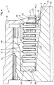
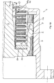
- Fig. 1 is a cross-sectional view of a conventional coupling with bellows-protected positive driving connection in the form of a two-tooth coupling halves tooth coupling 30 with crowned teeth 2 and in Fig. 2 Turns to an enlarged cross-sectional view of the sleeve-hub portion of the conventional toothed coupling 30 with crowning 2 and the Basgveriereung 2 associated bellows seal after Fig. 1 for rail vehicles according to the publication DE 196 44 884 B4 shown.
- the toothed coupling 30 thus comprises at least one toothed clutch hub 3 and a sleeve 4 closing the toothed clutch hub 3, the toothing 2 being arranged between the hub 3 and the sleeve 4, the toothing 2 being protected by a ring-shaped corrugated bellows 5 as a bellows seal, wherein the bellows 5 is located in a recess 6 of the hub 3 in the form of a cavity and is fastened on the one hand to the sleeve end region 8 and on the other hand to the sleeve end region 8 on the hub 3 at a connection point 26, wherein the annular recess 6 is substantially delimited by an annular hub inner surface 16 directed towards the toothing 2 and by an opposite hub outer surface 9 formed to the end face 11 of the hub 3, wherein an annular gap 10 between the sleeve end region 8 and the hub outer surface 9 of the recess 6 forms a bellows clearance 20 opens.
- the present invention is therefore intended to be useful not only for toothed couplings 30 with crowned teeth 2, but also for couplings with bellows-protected teeth 2 and built-in toothing 2 associated Balgabdichtung.
- Said recess 6 of the hub 3 is bounded by the hub inner surface 16, the hub outer surface 9 and the hub inner surface 16 and the hub outer surface 9 connecting transition surface 22, in the region of the bellows 5 is attached on the one hand.
- the bellows 5 is placed in the cavity of the recess 6 and on the other hand at the end 7 of the recess 6 almost occlusive Hülsenend Schemees 8 is attached.
- the annular bellows 5 also represents the elastic closure for the toothing 2 between hub 3 and sleeve 4. Between the end 7 of the sleeve end region 8 including the bellows holder 13 and the hub outer surface 9, the annular gap 10 is formed.
- the corrugated bellows 5 is defined:
- the bellows 5 represents a ring element, the surface of which has a wave-shaped cross-section.
- the troughs of the bellows 5 directed toward the hub outer surface 9 are referred to as bellows clearances 21.
- the part of the recess 6 between the bellows clearance 21 and the hub outer surface 9 is referred to below as the bellows clearance 20.
- a disadvantage is that both the bellows 5 and the bellows clearance 20, but in particular the bellows 5 formed Balgelementzaschreib 21 in the area between the bellows 5 and the hub outer surface 9 are not protected from dirt and dust particles.
- Balgelementar 21 are affected by cumbersome dirt and Staubteilchenstromrungen, the accumulated particles reduce the elasticity of the bellows elements 25 and thus the said displacements.
- the invention is therefore based on the object to provide a coupling with bellows-protected positive driving connection, which is designed so that the penetration of dust and dirt in the driving connection, e.g. the bellows averted bellows clearance, in particular in the trained in cross-section as wave troughs and the hub outer surface facing Balgelementokopathy the existing within the hub recess in the area between bellows and hub outer surface can be avoided.
- the coupling with bellows-protected positive driving connection comprising at least one hub and a sleeve, wherein the driving connection is arranged between the hub and sleeve, wherein the driving connection is protected by a bellows, wherein the bellows is located in a recess of the hub and on the one hand on Hülsenend Scheme and on the other the sleeve end region is fastened to the hub at a connection point, wherein the annular recess is substantially delimited by an annular hub inner surface facing the driving engagement and by an opposite hub outer surface formed to the end face of the hub, an annular gap being present between the sleeve end region and the hub outer surface of the recess, wherein according to the characterizing part of patent claim 1 at least one elastic annular sealing element is arranged in the region between the corrugated annular bellows with bellows elements and the hub outer surface, wherein the sealing element seals at least one bellows-forming area of a bellows element which is adjacent to the
- the positive driving connection can represent a toothing.
- a first inventive elastic annular sealing element can be attached with a specially shaped ring outer region and with a specially shaped inner ring area at the sleeve end with the involvement of bellows by means of two the end of the Hommesenend Schemees partially enclosing ring outer region elongated annular lips and can have an outwardly directed elastic sealing lip in the inner ring area, the elastically and sealingly rests on the hub outer surface and closes the annular gap by its sealing lip-like support on the hub outer surface.
- the first elastic sealing element may be located at least in one, in particular in the first Balgelement free space as the ring outer region, wherein the first inside located annular lip, which is the Balgelementcardiraum a bellows element partially or completely adapted, and may have as ring inner region directed towards the end face of the hub elastic sealing lip.
- the first elastic annular sealing member may be made of an elastomer such as PUR plastic or rubber.
- a second inventive elastic annular sealing element can close the annular gap, wherein the second sealing element engages at least one of the Balgelementatism the recess belonging bellows clearance at least with the annular inner region of the second sealing element in the form of a sealing ring on the hub outer surface of the recess contacting.
- the second elastic annular sealing element can engage at least with its outer ring area in the form of an annular sealing lip, in particular in the first Balgelementokraum the closest to the Hülsenend Scheme Balgelementcardiraum lying on the hub of Hülsenend Schemees bellows.
- sealing ring of the second sealing element can be rectangular or square not only in cross-section, but can also be designed as an elastic to the front side of the hub directed inclined elastic, for displacements always on the hub outer surface contacting sealing lip.
- the second elastic annular sealing member may be made of polyethylene foam.
- a third inventive elastic annular sealing member may also close the annular gap, the third sealing member filling the hub opposite bellows clearance of the bellows in a bellows clearance, in several or all Balgelementokin in the form of annular sealing lips and with its ring inner region on the hub outer surface in the form of a preferably rectangular in cross-section or square sealing ring rests contacting.
- the third elastic annular sealing member may be made of foam, in particular polyethylene foam material.
- a fourth inventive elastic annular sealing member may be formed with each other in the ring inner region, the ring outer region performing annular sealing lips opposite the hub outer surface formed in cross section as wave troughs Balgelement cartitician the bellows elements in a Balgelement arthritisraum, in several or all Balgelementkaolin, the sealing member with its annular inner space is spaced from the hub outer surface and wherein the occupied Balgelement cartitician sealed and thus the bellows clearances are protected.
- the inserted into the Balgelement cartilage elastic material of the sealing elements can adhere firmly to the inner surface of the Balgelement cartitician or can be clamped in the Balgelement cartitician.
- the fourth elastic annular sealing member may be made of foam, in particular polyethylene foam.
- the inserted elastic annular sealing member may be formed into a combination sealing member by combining at least two of the above sealing members.
- both the bellows, in particular the bellows clearances are protected from dirt and dust.
- Fig. 3 is a cross-sectional view of a coupling according to the invention with bellows-protected positive driving connection in the form of two toothed coupling halves toothed coupling 1, each with a toothing 2 and a first elastic annular sealing member 121 between the bellows 5 and the bellows 5 opposite hub outer surface 9
- Fig. 4 is an enlarged view of the sleeve-hub region of the gear coupling according to the invention 1 with teeth 2 after Fig. 3 and the first elastic annular sealing member 121 between the bellows 5 and the bellows 5 opposite hub outer surface 9 shown.
- only one toothed coupling half is assigned reference numbers.
- the toothed coupling 1 shown there with toothing 2 comprises at least one hub 3 and a sleeve 4, wherein between the hub 3 and sleeve 4, the toothing 2 is arranged, wherein the toothing 2 is protected by the bellows 5, wherein the bellows 5 is in a recess 6 of the hub 3 is located and on the one hand at the sleeve end portion 8 and on the other hand, the sleeve end portion 8 opposite to the hub 3 is fixed to a connection point 26, wherein the annular recess 6 is essentially delimited by an annular hub inner surface 16 directed towards the toothing 2 and by an opposite hub outer surface 9 formed to the front side 11 of the hub 3, an annular gap 10 being present between the sleeve end region 8 and the hub outer surface 9 of the recess 6 and a bellows clearance 20 opens.
- an elastic annular sealing element 12, 121 is arranged in the region between the bellows 5 and the hub outer surface 9, the sealing element 12, 121 sealing at least the bellows clearance area 21 which is adjacent to the annular gap 10 and designed as a corrugation in cross-section.
- a first in Fig. 3 and one in Fig. 4 enlarged illustrated elastic annular sealing member 121 is formed such that it closes at least the annular gap 10 between the sleeve end portion 8 and the hub outer surface 9 of the hub 3.
- the recess 6 of the hub 3 is bounded by the hub 2 facing away from the inner surface 16 of the toothing 2 facing a hub outer surface 9 and a lying between the hub inner surface 16 and the hub outer surface 9 transition surface 22 with a junction 26, in the region of the bellows 5 on the other is.
- the bellows 5 is in the annular cavity of the recess. 6 placed and on the other hand at the end 7 of the sleeve end 8 by means of a bellows holder 13 is locked.
- the annular bellows 5 constitutes a protective closure for the toothing 2 between hub 3 and sleeve 4.
- the annular gap 10 is formed between the end 7 of the sleeve end region 8 including the bellows support 13 and the hub outer surface 9.
- the bellows clearances 21 are susceptible to contamination that affect the dynamic displacement possibilities between hub 3 and sleeve 4.
- a first elastic annular sealing element 121 with a specially shaped ring outer region 17 and with a specially shaped inner ring portion 18 at Hülsenend Scheme 8 with the involvement of the bellows holder 13 by means of two the end 7 of the Hülsenend Schemees 8 partially enclosing ring outer region 17 elongated retaining annular lips 14 and 15 attached , It has in the ring inner region 18 an outwardly directed elastic sealing lip 19 which rests elastically and sealingly on the hub outer surface 9 and closes the annular gap 10 by its sealing lip-like support on the hub outer surface 9.
- the first sealing member 121 at least in one, in particular in the first Balgelement free space 21, the first inner annular lip 14, formed as a ring lip 23 and the Balgelementcardi 21 partially or completely adapted to be located as ring outer region 17 and be designed as ring inner region 18 directed towards the end face 11 of the hub 3 elastic sealing lip 19.
- the first elastic annular sealing member 121 may be e.g. Made of elastic material PUR plastic.
- the ring inner region 18 can also be formed instead of the elastic sealing lip 19 as an elastic, rectangular cross-section sealing ring 24 which is homogeneously connected to the annular lip 14 as the ring outer region 17, as in Fig. 5 and in Fig. 6 is shown, so that the second elastic sealing member 122 described below is formed.
- Fig. 5 is a cross-sectional view of a toothed coupling 1 according to the invention with teeth 2 and a second elastic annular sealing member 122 between the bellows 5 and the bellows 5 opposite hub outer surface 9
- Fig. 6 an enlarged view of the sleeve-hub region of a toothed coupling 1 according to the invention with teeth 2 and the second elastic annular sealing member 122 between the bellows 5 and the bellows 5 opposite hub outer surface 9 shown.
- Fig. 6 is the second elastic annular sealing member 12, 122 indicated in an enlarged sectional view, which engages at least with its outer ring portion 17 in a bellows clearance 21 of lying in the hub 3 of the Hommesenend Schemees 8 bellows clearance 20 in the form of a thickened a Balgelementcardiraum 21 filling annular lip 23, wherein the Ring inner region 18 of the elastic sealing element 122 on the hub outer surface 9 of the recess 6 in the form of a relative to the annular lip 23 common sealing ring 24 contacts contacting.
- the second elastic annular sealing element 122 made of the elastic material may preferably consist of polyethylene (PE) foam.
- Fig. 7 is a cross-sectional view of a toothed coupling 1 according to the invention with teeth 2 and a third elastic annular sealing member 123 between the bellows 5 and the bellows 5 opposite hub outer surface 9 and in Fig. 8 an enlarged view of the sleeve-hub region of the toothed coupling 1 according to the invention with teeth 2 and the third elastic annular sealing element 123 between the bellows 5 and the bellows 5 opposite hub outer surface 9 is shown.
- the optionally foamed into the Balgelementokitati 21, engaging annular sealing lips 23 may be connected to each other inside the ring area.
- the annular ring 18 associated with the sealing ring 24 supports the existing and interconnected annular sealing lips 23 from the hub surface 9 from.
- the sealing ring 24 may therefore be formed offset from the foamed in the Balgelementokitati 21 and engaging annular sealing lips 23.
- the produced PE foam ring sealing lips 23 can be inserted into the bellows clearances 21 and thus biased.
- the third elastic annular sealing element 123 may consist of the elastic material polyethylene (PE) foam.
- Fig. 9 is a cross-sectional view of a toothed coupling 1 according to the invention with teeth 2 and a fourth elastic annular sealing member 124 between the bellows 5 and the bellows 5 opposite hub outer surface 9, wherein the fourth sealing member 124 completely fills the BalgelementokIER 21 and not rests directly on the hub outer surface 9, and in Fig. 10 an enlarged view of the sleeve-hub region of a toothed coupling 1 according to the invention with teeth 2 after Fig. 9 and the fourth elastic annular sealing member 124 between the bellows 5 and the bellows 5 opposite hub outer surface 9 shown.
- the fourth elastic annular sealing element 12, 124 is formed with annular sealing lips 23 which are connected to one another in the annular inner region 18 and fill the hub outer surface 9 opposite bellows clearances 21 of the bellows elements 25 preferably in all bellows clearances 21, the sealing element 124 having its annular inner region 18 from the hub outer surface 9 is arranged at a distance and wherein the occupied BalgelementokIER 21 sealed and thus the BalgelementokIER 21 are protected. Belonging to the recess 6 bellows clearance 20 is thus largely a free space without material.
- the fourth sealing element 124 essentially differs from the third sealing element 123 due to the absence of the sealing ring 24 or a contacting sealing lip 19 placed on the hub outer surface 9.
- the fourth elastic annular sealing member 123 may also consist of the elastic material polyethylene (PE) foam.
- both the bellows 5, in particular the bellows clearances 21 and also largely the hub outer surface 9 and also the junction 26 between the hub 3 and bellows 5 at the transition point 22 are safe from dirt and dust protected.
- the elastic annular sealing element 12 essentially represents an bellows protection element.
- the sealing elements 12; 121, 122, 123, 124 may be formed and manufactured such that the ring outer region 17 and inner ring region 18 are not separate parts, but parts of a sealing element 12 produced in one piece; 121, 122, 123, 124 represent.
- sealing elements 12; 121, 122, 123, 124 may also be designed and manufactured in such a manner that ring outer region 17 and inner ring region 18 are section parts produced separately, respectively ring outer region 17 and inner ring region 18 also comprise at least two region parts that belong to one of the sealing elements 12; 121, 122, 123, 124 joined together and preferably glued.
- the elastic annular sealing member 12 may be formed into a combination sealing member by combining at least two combinations of the aforementioned elastic sealing members 121, 122, 123, 124.
Landscapes
- Engineering & Computer Science (AREA)
- General Engineering & Computer Science (AREA)
- Mechanical Engineering (AREA)
- Transportation (AREA)
- Sealing Devices (AREA)
- Diaphragms And Bellows (AREA)
Priority Applications (1)
| Application Number | Priority Date | Filing Date | Title |
|---|---|---|---|
| PL14824771T PL3074670T3 (pl) | 2013-11-27 | 2014-11-18 | Sprzęgło z osłoniętym miechem kształtowym połączeniem zabierającym |
Applications Claiming Priority (2)
| Application Number | Priority Date | Filing Date | Title |
|---|---|---|---|
| DE202013010596.8U DE202013010596U1 (de) | 2013-11-27 | 2013-11-27 | Kupplung mit balggeschützter formschlüssiger Mitnahmeverbindung |
| PCT/DE2014/000595 WO2015078429A1 (de) | 2013-11-27 | 2014-11-18 | Kupplung mit balggeschützter formschlüssiger mitnahmeverbindung |
Publications (2)
| Publication Number | Publication Date |
|---|---|
| EP3074670A1 EP3074670A1 (de) | 2016-10-05 |
| EP3074670B1 true EP3074670B1 (de) | 2018-08-22 |
Family
ID=50070006
Family Applications (1)
| Application Number | Title | Priority Date | Filing Date |
|---|---|---|---|
| EP14824771.1A Active EP3074670B1 (de) | 2013-11-27 | 2014-11-18 | Kupplung mit balggeschützter formschlüssiger mitnahmeverbindung |
Country Status (9)
| Country | Link |
|---|---|
| US (1) | US10408275B2 (pl) |
| EP (1) | EP3074670B1 (pl) |
| CN (1) | CN105765254B (pl) |
| DE (1) | DE202013010596U1 (pl) |
| DK (1) | DK3074670T3 (pl) |
| ES (1) | ES2698999T3 (pl) |
| PL (1) | PL3074670T3 (pl) |
| PT (1) | PT3074670T (pl) |
| WO (1) | WO2015078429A1 (pl) |
Families Citing this family (3)
| Publication number | Priority date | Publication date | Assignee | Title |
|---|---|---|---|---|
| DE202013010596U1 (de) | 2013-11-27 | 2014-01-20 | Kwd Kupplungswerk Dresden Gmbh | Kupplung mit balggeschützter formschlüssiger Mitnahmeverbindung |
| DE102015007711A1 (de) * | 2015-06-17 | 2016-12-22 | HENKE Property UG (haftungsbeschränkt) | Doppelzahnkupplung zur Verbindung einer angetriebenen Welle mit einer getriebenen Welle |
| EP3536998B1 (en) * | 2018-03-05 | 2022-08-03 | Hamilton Sundstrand Corporation | Self-centering flexible coupling |
Family Cites Families (15)
| Publication number | Priority date | Publication date | Assignee | Title |
|---|---|---|---|---|
| US3953037A (en) * | 1973-04-06 | 1976-04-27 | Rodgard Manufacturing Co., Inc. | Polished rod protector and receiver |
| JPS5796094U (pl) * | 1980-12-03 | 1982-06-12 | ||
| DE3514497C2 (de) * | 1985-04-22 | 1995-11-09 | Teves Gmbh Alfred | Schutzmanschette für eine Bolzenführung einer Teilbelag-Scheibenbremse |
| BE1008101A3 (fr) | 1994-04-05 | 1996-01-16 | Paul Egide Boucquey | Accouplement de transmission d'un couple de rotation. |
| DE29610299U1 (de) * | 1996-06-12 | 1996-09-19 | KWD Kupplungswerk Dresden GmbH, 01159 Dresden | Zahnkupplung |
| DE20115407U1 (de) | 2001-09-12 | 2001-11-29 | KWD Kupplungswerk Dresden GmbH, 01159 Dresden | Drehmomentgeschaltete Reibungskupplung |
| DE202006010830U1 (de) | 2006-07-04 | 2006-09-28 | Kwd Kupplungswerk Dresden Gmbh | Zahnkupplungs-Gelenkwelle |
| DE202006019190U1 (de) * | 2006-12-15 | 2008-04-24 | Kwd Kupplungswerk Dresden Gmbh | Federdruck-Lamellenkupplung für Kompressoren |
| DE102008014695B4 (de) * | 2008-03-18 | 2023-08-03 | THK RHYTHM AUTOMOTIVE GmbH | Dichtungsbaugruppe eines Kugelgelenks sowie Kugelgelenk |
| US8684621B2 (en) * | 2009-06-30 | 2014-04-01 | Trw Automotive Gmbh | Ball joint |
| CN201531695U (zh) * | 2009-10-16 | 2010-07-21 | 北京哈威工程材料有限责任公司 | 一种双壁波纹管用密封胶圈 |
| DE102010061819A1 (de) * | 2010-11-24 | 2012-05-24 | Aktiebolaget Skf | Radialwellendichtring |
| WO2012107015A2 (de) * | 2011-02-10 | 2012-08-16 | Schaeffler Technologies AG & Co. KG | Dichtung für eine hydraulische kolben-zylinder-anordnung |
| JP5079167B1 (ja) * | 2011-09-07 | 2012-11-21 | 三菱電機株式会社 | ギアカップリング |
| DE202013010596U1 (de) | 2013-11-27 | 2014-01-20 | Kwd Kupplungswerk Dresden Gmbh | Kupplung mit balggeschützter formschlüssiger Mitnahmeverbindung |
-
2013
- 2013-11-27 DE DE202013010596.8U patent/DE202013010596U1/de not_active Expired - Lifetime
-
2014
- 2014-11-18 DK DK14824771.1T patent/DK3074670T3/en active
- 2014-11-18 ES ES14824771T patent/ES2698999T3/es active Active
- 2014-11-18 PT PT14824771T patent/PT3074670T/pt unknown
- 2014-11-18 US US15/100,125 patent/US10408275B2/en active Active
- 2014-11-18 EP EP14824771.1A patent/EP3074670B1/de active Active
- 2014-11-18 PL PL14824771T patent/PL3074670T3/pl unknown
- 2014-11-18 WO PCT/DE2014/000595 patent/WO2015078429A1/de not_active Ceased
- 2014-11-18 CN CN201480064917.6A patent/CN105765254B/zh active Active
Non-Patent Citations (1)
| Title |
|---|
| None * |
Also Published As
| Publication number | Publication date |
|---|---|
| DK3074670T3 (en) | 2018-12-17 |
| ES2698999T3 (es) | 2019-02-06 |
| PL3074670T3 (pl) | 2019-05-31 |
| US10408275B2 (en) | 2019-09-10 |
| DE202013010596U1 (de) | 2014-01-20 |
| PT3074670T (pt) | 2018-11-29 |
| US20170261041A1 (en) | 2017-09-14 |
| CN105765254A (zh) | 2016-07-13 |
| EP3074670A1 (de) | 2016-10-05 |
| WO2015078429A1 (de) | 2015-06-04 |
| CN105765254B (zh) | 2019-02-19 |
Similar Documents
| Publication | Publication Date | Title |
|---|---|---|
| DE102008014695B4 (de) | Dichtungsbaugruppe eines Kugelgelenks sowie Kugelgelenk | |
| DE69204421T2 (de) | Dichtungsring, insbesondere für Wälzlager. | |
| EP3074670B1 (de) | Kupplung mit balggeschützter formschlüssiger mitnahmeverbindung | |
| DE102014210732A1 (de) | Lageranordnung, umfassend einem optimierten Dichtring mit Dichtelement | |
| DE102011117820A1 (de) | Dichtring mit Führungselement | |
| EP3134283A1 (de) | Fahrzeugkarosseriedichtung mit zierleiste | |
| DE202018105005U1 (de) | Gehäuseintegration | |
| DE102015225165A1 (de) | Wälzlager, umfassend einen Dichtflansch | |
| DE3135982A1 (de) | "kraftstoffbehaelter, insbesondere aus kunststoff bestehender kraftstoffbehaelter" | |
| WO2013093900A1 (de) | Maul- oder klauenförmige spaltdichtung | |
| DE102014007798A1 (de) | Buchsenanordnung zur Zentrierung zweier zu verbindender Wellenabschnitte | |
| WO2012160148A1 (de) | Dichtlippe und dichtung | |
| EP2986872A1 (de) | Dichtungsmanschette für eine drehgelenkkupplung | |
| DE102008038766B4 (de) | Hydraulische Zahnradmaschine | |
| EP0863334B1 (de) | Faltenbalg | |
| DE102012105290A1 (de) | Tülle | |
| WO2008052610A1 (de) | Dichtsystem mit stützsteg im flanschbereich | |
| DE102016116922A1 (de) | Axialsicherung für eine Wellenanordnung | |
| DE102007048119B4 (de) | Dichtring für eine Steckmuffenverbindung zweier Rohre | |
| DE202013104759U1 (de) | Stufenlos drehverstellbarer Winkelsteckverbinder | |
| DE202013007855U1 (de) | Dichteinrichtung für Rohrverbindungen | |
| DE102015217419A1 (de) | Federbeingleitlager | |
| DE102011013366B4 (de) | Gleitringdichtung | |
| EP1828631B1 (de) | System zur befestigung eines faltenbalgs auf einem bauteil mit mindestens einem loben bereich | |
| DE102007036732B3 (de) | Befestigungsclip |
Legal Events
| Date | Code | Title | Description |
|---|---|---|---|
| PUAI | Public reference made under article 153(3) epc to a published international application that has entered the european phase |
Free format text: ORIGINAL CODE: 0009012 |
|
| 17P | Request for examination filed |
Effective date: 20160520 |
|
| AK | Designated contracting states |
Kind code of ref document: A1 Designated state(s): AL AT BE BG CH CY CZ DE DK EE ES FI FR GB GR HR HU IE IS IT LI LT LU LV MC MK MT NL NO PL PT RO RS SE SI SK SM TR |
|
| AX | Request for extension of the european patent |
Extension state: BA ME |
|
| DAX | Request for extension of the european patent (deleted) | ||
| STAA | Information on the status of an ep patent application or granted ep patent |
Free format text: STATUS: EXAMINATION IS IN PROGRESS |
|
| 17Q | First examination report despatched |
Effective date: 20171109 |
|
| REG | Reference to a national code |
Ref country code: DE Ref legal event code: R079 Ref document number: 502014009280 Country of ref document: DE Free format text: PREVIOUS MAIN CLASS: F16J0015520000 Ipc: F16D0003740000 |
|
| RIC1 | Information provided on ipc code assigned before grant |
Ipc: F16D 3/74 20060101AFI20180213BHEP Ipc: F16J 15/52 20060101ALI20180213BHEP |
|
| GRAP | Despatch of communication of intention to grant a patent |
Free format text: ORIGINAL CODE: EPIDOSNIGR1 |
|
| STAA | Information on the status of an ep patent application or granted ep patent |
Free format text: STATUS: GRANT OF PATENT IS INTENDED |
|
| INTG | Intention to grant announced |
Effective date: 20180323 |
|
| GRAS | Grant fee paid |
Free format text: ORIGINAL CODE: EPIDOSNIGR3 |
|
| GRAA | (expected) grant |
Free format text: ORIGINAL CODE: 0009210 |
|
| STAA | Information on the status of an ep patent application or granted ep patent |
Free format text: STATUS: THE PATENT HAS BEEN GRANTED |
|
| AK | Designated contracting states |
Kind code of ref document: B1 Designated state(s): AL AT BE BG CH CY CZ DE DK EE ES FI FR GB GR HR HU IE IS IT LI LT LU LV MC MK MT NL NO PL PT RO RS SE SI SK SM TR |
|
| REG | Reference to a national code |
Ref country code: GB Ref legal event code: FG4D Free format text: NOT ENGLISH |
|
| REG | Reference to a national code |
Ref country code: CH Ref legal event code: EP |
|
| REG | Reference to a national code |
Ref country code: AT Ref legal event code: REF Ref document number: 1032882 Country of ref document: AT Kind code of ref document: T Effective date: 20180915 |
|
| REG | Reference to a national code |
Ref country code: IE Ref legal event code: FG4D Free format text: LANGUAGE OF EP DOCUMENT: GERMAN |
|
| REG | Reference to a national code |
Ref country code: DE Ref legal event code: R096 Ref document number: 502014009280 Country of ref document: DE |
|
| REG | Reference to a national code |
Ref country code: PT Ref legal event code: SC4A Ref document number: 3074670 Country of ref document: PT Date of ref document: 20181129 Kind code of ref document: T Free format text: AVAILABILITY OF NATIONAL TRANSLATION Effective date: 20181120 |
|
| REG | Reference to a national code |
Ref country code: SE Ref legal event code: TRGR |
|
| REG | Reference to a national code |
Ref country code: NL Ref legal event code: FP |
|
| REG | Reference to a national code |
Ref country code: DK Ref legal event code: T3 Effective date: 20181210 |
|
| REG | Reference to a national code |
Ref country code: LT Ref legal event code: MG4D |
|
| PG25 | Lapsed in a contracting state [announced via postgrant information from national office to epo] |
Ref country code: NO Free format text: LAPSE BECAUSE OF FAILURE TO SUBMIT A TRANSLATION OF THE DESCRIPTION OR TO PAY THE FEE WITHIN THE PRESCRIBED TIME-LIMIT Effective date: 20181122 Ref country code: LT Free format text: LAPSE BECAUSE OF FAILURE TO SUBMIT A TRANSLATION OF THE DESCRIPTION OR TO PAY THE FEE WITHIN THE PRESCRIBED TIME-LIMIT Effective date: 20180822 Ref country code: RS Free format text: LAPSE BECAUSE OF FAILURE TO SUBMIT A TRANSLATION OF THE DESCRIPTION OR TO PAY THE FEE WITHIN THE PRESCRIBED TIME-LIMIT Effective date: 20180822 Ref country code: IS Free format text: LAPSE BECAUSE OF FAILURE TO SUBMIT A TRANSLATION OF THE DESCRIPTION OR TO PAY THE FEE WITHIN THE PRESCRIBED TIME-LIMIT Effective date: 20181222 Ref country code: BG Free format text: LAPSE BECAUSE OF FAILURE TO SUBMIT A TRANSLATION OF THE DESCRIPTION OR TO PAY THE FEE WITHIN THE PRESCRIBED TIME-LIMIT Effective date: 20181122 |
|
| REG | Reference to a national code |
Ref country code: ES Ref legal event code: FG2A Ref document number: 2698999 Country of ref document: ES Kind code of ref document: T3 Effective date: 20190206 |
|
| PG25 | Lapsed in a contracting state [announced via postgrant information from national office to epo] |
Ref country code: AL Free format text: LAPSE BECAUSE OF FAILURE TO SUBMIT A TRANSLATION OF THE DESCRIPTION OR TO PAY THE FEE WITHIN THE PRESCRIBED TIME-LIMIT Effective date: 20180822 Ref country code: LV Free format text: LAPSE BECAUSE OF FAILURE TO SUBMIT A TRANSLATION OF THE DESCRIPTION OR TO PAY THE FEE WITHIN THE PRESCRIBED TIME-LIMIT Effective date: 20180822 Ref country code: HR Free format text: LAPSE BECAUSE OF FAILURE TO SUBMIT A TRANSLATION OF THE DESCRIPTION OR TO PAY THE FEE WITHIN THE PRESCRIBED TIME-LIMIT Effective date: 20180822 |
|
| REG | Reference to a national code |
Ref country code: SK Ref legal event code: T3 Ref document number: E 29436 Country of ref document: SK |
|
| REG | Reference to a national code |
Ref country code: GR Ref legal event code: EP Ref document number: 20180403462 Country of ref document: GR Effective date: 20190320 |
|
| PG25 | Lapsed in a contracting state [announced via postgrant information from national office to epo] |
Ref country code: EE Free format text: LAPSE BECAUSE OF FAILURE TO SUBMIT A TRANSLATION OF THE DESCRIPTION OR TO PAY THE FEE WITHIN THE PRESCRIBED TIME-LIMIT Effective date: 20180822 Ref country code: RO Free format text: LAPSE BECAUSE OF FAILURE TO SUBMIT A TRANSLATION OF THE DESCRIPTION OR TO PAY THE FEE WITHIN THE PRESCRIBED TIME-LIMIT Effective date: 20180822 |
|
| REG | Reference to a national code |
Ref country code: DE Ref legal event code: R097 Ref document number: 502014009280 Country of ref document: DE |
|
| PG25 | Lapsed in a contracting state [announced via postgrant information from national office to epo] |
Ref country code: SM Free format text: LAPSE BECAUSE OF FAILURE TO SUBMIT A TRANSLATION OF THE DESCRIPTION OR TO PAY THE FEE WITHIN THE PRESCRIBED TIME-LIMIT Effective date: 20180822 |
|
| PLBE | No opposition filed within time limit |
Free format text: ORIGINAL CODE: 0009261 |
|
| STAA | Information on the status of an ep patent application or granted ep patent |
Free format text: STATUS: NO OPPOSITION FILED WITHIN TIME LIMIT |
|
| 26N | No opposition filed |
Effective date: 20190523 |
|
| PG25 | Lapsed in a contracting state [announced via postgrant information from national office to epo] |
Ref country code: SI Free format text: LAPSE BECAUSE OF FAILURE TO SUBMIT A TRANSLATION OF THE DESCRIPTION OR TO PAY THE FEE WITHIN THE PRESCRIBED TIME-LIMIT Effective date: 20180822 |
|
| PG25 | Lapsed in a contracting state [announced via postgrant information from national office to epo] |
Ref country code: MT Free format text: LAPSE BECAUSE OF FAILURE TO SUBMIT A TRANSLATION OF THE DESCRIPTION OR TO PAY THE FEE WITHIN THE PRESCRIBED TIME-LIMIT Effective date: 20180822 |
|
| PG25 | Lapsed in a contracting state [announced via postgrant information from national office to epo] |
Ref country code: TR Free format text: LAPSE BECAUSE OF FAILURE TO SUBMIT A TRANSLATION OF THE DESCRIPTION OR TO PAY THE FEE WITHIN THE PRESCRIBED TIME-LIMIT Effective date: 20180822 |
|
| PG25 | Lapsed in a contracting state [announced via postgrant information from national office to epo] |
Ref country code: MK Free format text: LAPSE BECAUSE OF NON-PAYMENT OF DUE FEES Effective date: 20180822 Ref country code: CY Free format text: LAPSE BECAUSE OF FAILURE TO SUBMIT A TRANSLATION OF THE DESCRIPTION OR TO PAY THE FEE WITHIN THE PRESCRIBED TIME-LIMIT Effective date: 20180822 Ref country code: HU Free format text: LAPSE BECAUSE OF FAILURE TO SUBMIT A TRANSLATION OF THE DESCRIPTION OR TO PAY THE FEE WITHIN THE PRESCRIBED TIME-LIMIT; INVALID AB INITIO Effective date: 20141118 |
|
| P01 | Opt-out of the competence of the unified patent court (upc) registered |
Effective date: 20230526 |
|
| REG | Reference to a national code |
Ref country code: CH Ref legal event code: U11 Free format text: ST27 STATUS EVENT CODE: U-0-0-U10-U11 (AS PROVIDED BY THE NATIONAL OFFICE) Effective date: 20251201 |
|
| PGFP | Annual fee paid to national office [announced via postgrant information from national office to epo] |
Ref country code: PT Payment date: 20251112 Year of fee payment: 12 |
|
| PGFP | Annual fee paid to national office [announced via postgrant information from national office to epo] |
Ref country code: LU Payment date: 20251118 Year of fee payment: 12 Ref country code: NL Payment date: 20251119 Year of fee payment: 12 |
|
| PGFP | Annual fee paid to national office [announced via postgrant information from national office to epo] |
Ref country code: DE Payment date: 20251118 Year of fee payment: 12 |
|
| PGFP | Annual fee paid to national office [announced via postgrant information from national office to epo] |
Ref country code: GB Payment date: 20251120 Year of fee payment: 12 |
|
| PGFP | Annual fee paid to national office [announced via postgrant information from national office to epo] |
Ref country code: MC Payment date: 20251118 Year of fee payment: 12 |
|
| PGFP | Annual fee paid to national office [announced via postgrant information from national office to epo] |
Ref country code: AT Payment date: 20251117 Year of fee payment: 12 |
|
| PGFP | Annual fee paid to national office [announced via postgrant information from national office to epo] |
Ref country code: IT Payment date: 20251128 Year of fee payment: 12 Ref country code: FI Payment date: 20251118 Year of fee payment: 12 Ref country code: DK Payment date: 20251119 Year of fee payment: 12 |
|
| PGFP | Annual fee paid to national office [announced via postgrant information from national office to epo] |
Ref country code: FR Payment date: 20251120 Year of fee payment: 12 |
|
| PGFP | Annual fee paid to national office [announced via postgrant information from national office to epo] |
Ref country code: BE Payment date: 20251118 Year of fee payment: 12 Ref country code: GR Payment date: 20251117 Year of fee payment: 12 |
|
| PGFP | Annual fee paid to national office [announced via postgrant information from national office to epo] |
Ref country code: SE Payment date: 20251119 Year of fee payment: 12 Ref country code: CH Payment date: 20251201 Year of fee payment: 12 |
|
| PGFP | Annual fee paid to national office [announced via postgrant information from national office to epo] |
Ref country code: IE Payment date: 20251120 Year of fee payment: 12 Ref country code: CZ Payment date: 20251113 Year of fee payment: 12 |
|
| PGFP | Annual fee paid to national office [announced via postgrant information from national office to epo] |
Ref country code: PL Payment date: 20251114 Year of fee payment: 12 |
|
| PGFP | Annual fee paid to national office [announced via postgrant information from national office to epo] |
Ref country code: SK Payment date: 20251113 Year of fee payment: 12 |
|
| PGFP | Annual fee paid to national office [announced via postgrant information from national office to epo] |
Ref country code: ES Payment date: 20251216 Year of fee payment: 12 |