EP3074670B1 - Kupplung mit balggeschützter formschlüssiger mitnahmeverbindung - Google Patents
Kupplung mit balggeschützter formschlüssiger mitnahmeverbindung Download PDFInfo
- Publication number
- EP3074670B1 EP3074670B1 EP14824771.1A EP14824771A EP3074670B1 EP 3074670 B1 EP3074670 B1 EP 3074670B1 EP 14824771 A EP14824771 A EP 14824771A EP 3074670 B1 EP3074670 B1 EP 3074670B1
- Authority
- EP
- European Patent Office
- Prior art keywords
- annular
- gaiter
- hub
- elastic
- region
- Prior art date
- Legal status (The legal status is an assumption and is not a legal conclusion. Google has not performed a legal analysis and makes no representation as to the accuracy of the status listed.)
- Active
Links
Images


Classifications
-
- F—MECHANICAL ENGINEERING; LIGHTING; HEATING; WEAPONS; BLASTING
- F16—ENGINEERING ELEMENTS AND UNITS; GENERAL MEASURES FOR PRODUCING AND MAINTAINING EFFECTIVE FUNCTIONING OF MACHINES OR INSTALLATIONS; THERMAL INSULATION IN GENERAL
- F16D—COUPLINGS FOR TRANSMITTING ROTATION; CLUTCHES; BRAKES
- F16D3/00—Yielding couplings, i.e. with means permitting movement between the connected parts during the drive
- F16D3/16—Universal joints in which flexibility is produced by means of pivots or sliding or rolling connecting parts
- F16D3/18—Universal joints in which flexibility is produced by means of pivots or sliding or rolling connecting parts the coupling parts (1) having slidably-interengaging teeth
-
- F—MECHANICAL ENGINEERING; LIGHTING; HEATING; WEAPONS; BLASTING
- F16—ENGINEERING ELEMENTS AND UNITS; GENERAL MEASURES FOR PRODUCING AND MAINTAINING EFFECTIVE FUNCTIONING OF MACHINES OR INSTALLATIONS; THERMAL INSULATION IN GENERAL
- F16D—COUPLINGS FOR TRANSMITTING ROTATION; CLUTCHES; BRAKES
- F16D3/00—Yielding couplings, i.e. with means permitting movement between the connected parts during the drive
- F16D3/50—Yielding couplings, i.e. with means permitting movement between the connected parts during the drive with the coupling parts connected by one or more intermediate members
- F16D3/72—Yielding couplings, i.e. with means permitting movement between the connected parts during the drive with the coupling parts connected by one or more intermediate members with axially-spaced attachments to the coupling parts
- F16D3/74—Yielding couplings, i.e. with means permitting movement between the connected parts during the drive with the coupling parts connected by one or more intermediate members with axially-spaced attachments to the coupling parts the intermediate member or members being made of rubber or other rubber-like flexible material
-
- B—PERFORMING OPERATIONS; TRANSPORTING
- B61—RAILWAYS
- B61C—LOCOMOTIVES; MOTOR RAILCARS
- B61C9/00—Locomotives or motor railcars characterised by the type of transmission system used; Transmission systems specially adapted for locomotives or motor railcars
-
- F—MECHANICAL ENGINEERING; LIGHTING; HEATING; WEAPONS; BLASTING
- F16—ENGINEERING ELEMENTS AND UNITS; GENERAL MEASURES FOR PRODUCING AND MAINTAINING EFFECTIVE FUNCTIONING OF MACHINES OR INSTALLATIONS; THERMAL INSULATION IN GENERAL
- F16D—COUPLINGS FOR TRANSMITTING ROTATION; CLUTCHES; BRAKES
- F16D3/00—Yielding couplings, i.e. with means permitting movement between the connected parts during the drive
- F16D3/16—Universal joints in which flexibility is produced by means of pivots or sliding or rolling connecting parts
- F16D3/18—Universal joints in which flexibility is produced by means of pivots or sliding or rolling connecting parts the coupling parts (1) having slidably-interengaging teeth
- F16D3/185—Universal joints in which flexibility is produced by means of pivots or sliding or rolling connecting parts the coupling parts (1) having slidably-interengaging teeth radial teeth connecting concentric inner and outer coupling parts
-
- F—MECHANICAL ENGINEERING; LIGHTING; HEATING; WEAPONS; BLASTING
- F16—ENGINEERING ELEMENTS AND UNITS; GENERAL MEASURES FOR PRODUCING AND MAINTAINING EFFECTIVE FUNCTIONING OF MACHINES OR INSTALLATIONS; THERMAL INSULATION IN GENERAL
- F16D—COUPLINGS FOR TRANSMITTING ROTATION; CLUTCHES; BRAKES
- F16D3/00—Yielding couplings, i.e. with means permitting movement between the connected parts during the drive
- F16D3/84—Shrouds, e.g. casings, covers; Sealing means specially adapted therefor
- F16D3/843—Shrouds, e.g. casings, covers; Sealing means specially adapted therefor enclosed covers
- F16D3/845—Shrouds, e.g. casings, covers; Sealing means specially adapted therefor enclosed covers allowing relative movement of joint parts due to the flexing of the cover
-
- F—MECHANICAL ENGINEERING; LIGHTING; HEATING; WEAPONS; BLASTING
- F16—ENGINEERING ELEMENTS AND UNITS; GENERAL MEASURES FOR PRODUCING AND MAINTAINING EFFECTIVE FUNCTIONING OF MACHINES OR INSTALLATIONS; THERMAL INSULATION IN GENERAL
- F16J—PISTONS; CYLINDERS; SEALINGS
- F16J15/00—Sealings
- F16J15/02—Sealings between relatively-stationary surfaces
- F16J15/06—Sealings between relatively-stationary surfaces with solid packing compressed between sealing surfaces
-
- F—MECHANICAL ENGINEERING; LIGHTING; HEATING; WEAPONS; BLASTING
- F16—ENGINEERING ELEMENTS AND UNITS; GENERAL MEASURES FOR PRODUCING AND MAINTAINING EFFECTIVE FUNCTIONING OF MACHINES OR INSTALLATIONS; THERMAL INSULATION IN GENERAL
- F16J—PISTONS; CYLINDERS; SEALINGS
- F16J15/00—Sealings
- F16J15/50—Sealings between relatively-movable members, by means of a sealing without relatively-moving surfaces, e.g. fluid-tight sealings for transmitting motion through a wall
- F16J15/52—Sealings between relatively-movable members, by means of a sealing without relatively-moving surfaces, e.g. fluid-tight sealings for transmitting motion through a wall by means of sealing bellows or diaphragms
Definitions
- the invention relates to a coupling with bellows-protected positive driving connection.
- Fig. 1 is a cross-sectional view of a conventional coupling with bellows-protected positive driving connection in the form of a two-tooth coupling halves tooth coupling 30 with crowned teeth 2 and in Fig. 2 Turns to an enlarged cross-sectional view of the sleeve-hub portion of the conventional toothed coupling 30 with crowning 2 and the Basgveriereung 2 associated bellows seal after Fig. 1 for rail vehicles according to the publication DE 196 44 884 B4 shown.
- the toothed coupling 30 thus comprises at least one toothed clutch hub 3 and a sleeve 4 closing the toothed clutch hub 3, the toothing 2 being arranged between the hub 3 and the sleeve 4, the toothing 2 being protected by a ring-shaped corrugated bellows 5 as a bellows seal, wherein the bellows 5 is located in a recess 6 of the hub 3 in the form of a cavity and is fastened on the one hand to the sleeve end region 8 and on the other hand to the sleeve end region 8 on the hub 3 at a connection point 26, wherein the annular recess 6 is substantially delimited by an annular hub inner surface 16 directed towards the toothing 2 and by an opposite hub outer surface 9 formed to the end face 11 of the hub 3, wherein an annular gap 10 between the sleeve end region 8 and the hub outer surface 9 of the recess 6 forms a bellows clearance 20 opens.
- the present invention is therefore intended to be useful not only for toothed couplings 30 with crowned teeth 2, but also for couplings with bellows-protected teeth 2 and built-in toothing 2 associated Balgabdichtung.
- Said recess 6 of the hub 3 is bounded by the hub inner surface 16, the hub outer surface 9 and the hub inner surface 16 and the hub outer surface 9 connecting transition surface 22, in the region of the bellows 5 is attached on the one hand.
- the bellows 5 is placed in the cavity of the recess 6 and on the other hand at the end 7 of the recess 6 almost occlusive Hülsenend Schemees 8 is attached.
- the annular bellows 5 also represents the elastic closure for the toothing 2 between hub 3 and sleeve 4. Between the end 7 of the sleeve end region 8 including the bellows holder 13 and the hub outer surface 9, the annular gap 10 is formed.
- the corrugated bellows 5 is defined:
- the bellows 5 represents a ring element, the surface of which has a wave-shaped cross-section.
- the troughs of the bellows 5 directed toward the hub outer surface 9 are referred to as bellows clearances 21.
- the part of the recess 6 between the bellows clearance 21 and the hub outer surface 9 is referred to below as the bellows clearance 20.
- a disadvantage is that both the bellows 5 and the bellows clearance 20, but in particular the bellows 5 formed Balgelementzaschreib 21 in the area between the bellows 5 and the hub outer surface 9 are not protected from dirt and dust particles.
- Balgelementar 21 are affected by cumbersome dirt and Staubteilchenstromrungen, the accumulated particles reduce the elasticity of the bellows elements 25 and thus the said displacements.
- the invention is therefore based on the object to provide a coupling with bellows-protected positive driving connection, which is designed so that the penetration of dust and dirt in the driving connection, e.g. the bellows averted bellows clearance, in particular in the trained in cross-section as wave troughs and the hub outer surface facing Balgelementokopathy the existing within the hub recess in the area between bellows and hub outer surface can be avoided.
- the coupling with bellows-protected positive driving connection comprising at least one hub and a sleeve, wherein the driving connection is arranged between the hub and sleeve, wherein the driving connection is protected by a bellows, wherein the bellows is located in a recess of the hub and on the one hand on Hülsenend Scheme and on the other the sleeve end region is fastened to the hub at a connection point, wherein the annular recess is substantially delimited by an annular hub inner surface facing the driving engagement and by an opposite hub outer surface formed to the end face of the hub, an annular gap being present between the sleeve end region and the hub outer surface of the recess, wherein according to the characterizing part of patent claim 1 at least one elastic annular sealing element is arranged in the region between the corrugated annular bellows with bellows elements and the hub outer surface, wherein the sealing element seals at least one bellows-forming area of a bellows element which is adjacent to the
- the positive driving connection can represent a toothing.
- a first inventive elastic annular sealing element can be attached with a specially shaped ring outer region and with a specially shaped inner ring area at the sleeve end with the involvement of bellows by means of two the end of the Hommesenend Schemees partially enclosing ring outer region elongated annular lips and can have an outwardly directed elastic sealing lip in the inner ring area, the elastically and sealingly rests on the hub outer surface and closes the annular gap by its sealing lip-like support on the hub outer surface.
- the first elastic sealing element may be located at least in one, in particular in the first Balgelement free space as the ring outer region, wherein the first inside located annular lip, which is the Balgelementcardiraum a bellows element partially or completely adapted, and may have as ring inner region directed towards the end face of the hub elastic sealing lip.
- the first elastic annular sealing member may be made of an elastomer such as PUR plastic or rubber.
- a second inventive elastic annular sealing element can close the annular gap, wherein the second sealing element engages at least one of the Balgelementatism the recess belonging bellows clearance at least with the annular inner region of the second sealing element in the form of a sealing ring on the hub outer surface of the recess contacting.
- the second elastic annular sealing element can engage at least with its outer ring area in the form of an annular sealing lip, in particular in the first Balgelementokraum the closest to the Hülsenend Scheme Balgelementcardiraum lying on the hub of Hülsenend Schemees bellows.
- sealing ring of the second sealing element can be rectangular or square not only in cross-section, but can also be designed as an elastic to the front side of the hub directed inclined elastic, for displacements always on the hub outer surface contacting sealing lip.
- the second elastic annular sealing member may be made of polyethylene foam.
- a third inventive elastic annular sealing member may also close the annular gap, the third sealing member filling the hub opposite bellows clearance of the bellows in a bellows clearance, in several or all Balgelementokin in the form of annular sealing lips and with its ring inner region on the hub outer surface in the form of a preferably rectangular in cross-section or square sealing ring rests contacting.
- the third elastic annular sealing member may be made of foam, in particular polyethylene foam material.
- a fourth inventive elastic annular sealing member may be formed with each other in the ring inner region, the ring outer region performing annular sealing lips opposite the hub outer surface formed in cross section as wave troughs Balgelement cartitician the bellows elements in a Balgelement arthritisraum, in several or all Balgelementkaolin, the sealing member with its annular inner space is spaced from the hub outer surface and wherein the occupied Balgelement cartitician sealed and thus the bellows clearances are protected.
- the inserted into the Balgelement cartilage elastic material of the sealing elements can adhere firmly to the inner surface of the Balgelement cartitician or can be clamped in the Balgelement cartitician.
- the fourth elastic annular sealing member may be made of foam, in particular polyethylene foam.
- the inserted elastic annular sealing member may be formed into a combination sealing member by combining at least two of the above sealing members.
- both the bellows, in particular the bellows clearances are protected from dirt and dust.
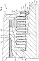
- Fig. 3 is a cross-sectional view of a coupling according to the invention with bellows-protected positive driving connection in the form of two toothed coupling halves toothed coupling 1, each with a toothing 2 and a first elastic annular sealing member 121 between the bellows 5 and the bellows 5 opposite hub outer surface 9
- Fig. 4 is an enlarged view of the sleeve-hub region of the gear coupling according to the invention 1 with teeth 2 after Fig. 3 and the first elastic annular sealing member 121 between the bellows 5 and the bellows 5 opposite hub outer surface 9 shown.
- only one toothed coupling half is assigned reference numbers.
- the toothed coupling 1 shown there with toothing 2 comprises at least one hub 3 and a sleeve 4, wherein between the hub 3 and sleeve 4, the toothing 2 is arranged, wherein the toothing 2 is protected by the bellows 5, wherein the bellows 5 is in a recess 6 of the hub 3 is located and on the one hand at the sleeve end portion 8 and on the other hand, the sleeve end portion 8 opposite to the hub 3 is fixed to a connection point 26, wherein the annular recess 6 is essentially delimited by an annular hub inner surface 16 directed towards the toothing 2 and by an opposite hub outer surface 9 formed to the front side 11 of the hub 3, an annular gap 10 being present between the sleeve end region 8 and the hub outer surface 9 of the recess 6 and a bellows clearance 20 opens.
- an elastic annular sealing element 12, 121 is arranged in the region between the bellows 5 and the hub outer surface 9, the sealing element 12, 121 sealing at least the bellows clearance area 21 which is adjacent to the annular gap 10 and designed as a corrugation in cross-section.
- a first in Fig. 3 and one in Fig. 4 enlarged illustrated elastic annular sealing member 121 is formed such that it closes at least the annular gap 10 between the sleeve end portion 8 and the hub outer surface 9 of the hub 3.
- the recess 6 of the hub 3 is bounded by the hub 2 facing away from the inner surface 16 of the toothing 2 facing a hub outer surface 9 and a lying between the hub inner surface 16 and the hub outer surface 9 transition surface 22 with a junction 26, in the region of the bellows 5 on the other is.
- the bellows 5 is in the annular cavity of the recess. 6 placed and on the other hand at the end 7 of the sleeve end 8 by means of a bellows holder 13 is locked.
- the annular bellows 5 constitutes a protective closure for the toothing 2 between hub 3 and sleeve 4.
- the annular gap 10 is formed between the end 7 of the sleeve end region 8 including the bellows support 13 and the hub outer surface 9.
- the bellows clearances 21 are susceptible to contamination that affect the dynamic displacement possibilities between hub 3 and sleeve 4.
- a first elastic annular sealing element 121 with a specially shaped ring outer region 17 and with a specially shaped inner ring portion 18 at Hülsenend Scheme 8 with the involvement of the bellows holder 13 by means of two the end 7 of the Hülsenend Schemees 8 partially enclosing ring outer region 17 elongated retaining annular lips 14 and 15 attached , It has in the ring inner region 18 an outwardly directed elastic sealing lip 19 which rests elastically and sealingly on the hub outer surface 9 and closes the annular gap 10 by its sealing lip-like support on the hub outer surface 9.
- the first sealing member 121 at least in one, in particular in the first Balgelement free space 21, the first inner annular lip 14, formed as a ring lip 23 and the Balgelementcardi 21 partially or completely adapted to be located as ring outer region 17 and be designed as ring inner region 18 directed towards the end face 11 of the hub 3 elastic sealing lip 19.
- the first elastic annular sealing member 121 may be e.g. Made of elastic material PUR plastic.
- the ring inner region 18 can also be formed instead of the elastic sealing lip 19 as an elastic, rectangular cross-section sealing ring 24 which is homogeneously connected to the annular lip 14 as the ring outer region 17, as in Fig. 5 and in Fig. 6 is shown, so that the second elastic sealing member 122 described below is formed.
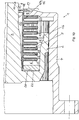
- Fig. 5 is a cross-sectional view of a toothed coupling 1 according to the invention with teeth 2 and a second elastic annular sealing member 122 between the bellows 5 and the bellows 5 opposite hub outer surface 9
- Fig. 6 an enlarged view of the sleeve-hub region of a toothed coupling 1 according to the invention with teeth 2 and the second elastic annular sealing member 122 between the bellows 5 and the bellows 5 opposite hub outer surface 9 shown.
- Fig. 6 is the second elastic annular sealing member 12, 122 indicated in an enlarged sectional view, which engages at least with its outer ring portion 17 in a bellows clearance 21 of lying in the hub 3 of the Hommesenend Schemees 8 bellows clearance 20 in the form of a thickened a Balgelementcardiraum 21 filling annular lip 23, wherein the Ring inner region 18 of the elastic sealing element 122 on the hub outer surface 9 of the recess 6 in the form of a relative to the annular lip 23 common sealing ring 24 contacts contacting.
- the second elastic annular sealing element 122 made of the elastic material may preferably consist of polyethylene (PE) foam.
- Fig. 7 is a cross-sectional view of a toothed coupling 1 according to the invention with teeth 2 and a third elastic annular sealing member 123 between the bellows 5 and the bellows 5 opposite hub outer surface 9 and in Fig. 8 an enlarged view of the sleeve-hub region of the toothed coupling 1 according to the invention with teeth 2 and the third elastic annular sealing element 123 between the bellows 5 and the bellows 5 opposite hub outer surface 9 is shown.
- the optionally foamed into the Balgelementokitati 21, engaging annular sealing lips 23 may be connected to each other inside the ring area.
- the annular ring 18 associated with the sealing ring 24 supports the existing and interconnected annular sealing lips 23 from the hub surface 9 from.
- the sealing ring 24 may therefore be formed offset from the foamed in the Balgelementokitati 21 and engaging annular sealing lips 23.
- the produced PE foam ring sealing lips 23 can be inserted into the bellows clearances 21 and thus biased.
- the third elastic annular sealing element 123 may consist of the elastic material polyethylene (PE) foam.
- Fig. 9 is a cross-sectional view of a toothed coupling 1 according to the invention with teeth 2 and a fourth elastic annular sealing member 124 between the bellows 5 and the bellows 5 opposite hub outer surface 9, wherein the fourth sealing member 124 completely fills the BalgelementokIER 21 and not rests directly on the hub outer surface 9, and in Fig. 10 an enlarged view of the sleeve-hub region of a toothed coupling 1 according to the invention with teeth 2 after Fig. 9 and the fourth elastic annular sealing member 124 between the bellows 5 and the bellows 5 opposite hub outer surface 9 shown.
- the fourth elastic annular sealing element 12, 124 is formed with annular sealing lips 23 which are connected to one another in the annular inner region 18 and fill the hub outer surface 9 opposite bellows clearances 21 of the bellows elements 25 preferably in all bellows clearances 21, the sealing element 124 having its annular inner region 18 from the hub outer surface 9 is arranged at a distance and wherein the occupied BalgelementokIER 21 sealed and thus the BalgelementokIER 21 are protected. Belonging to the recess 6 bellows clearance 20 is thus largely a free space without material.
- the fourth sealing element 124 essentially differs from the third sealing element 123 due to the absence of the sealing ring 24 or a contacting sealing lip 19 placed on the hub outer surface 9.
- the fourth elastic annular sealing member 123 may also consist of the elastic material polyethylene (PE) foam.
- both the bellows 5, in particular the bellows clearances 21 and also largely the hub outer surface 9 and also the junction 26 between the hub 3 and bellows 5 at the transition point 22 are safe from dirt and dust protected.
- the elastic annular sealing element 12 essentially represents an bellows protection element.
- the sealing elements 12; 121, 122, 123, 124 may be formed and manufactured such that the ring outer region 17 and inner ring region 18 are not separate parts, but parts of a sealing element 12 produced in one piece; 121, 122, 123, 124 represent.
- sealing elements 12; 121, 122, 123, 124 may also be designed and manufactured in such a manner that ring outer region 17 and inner ring region 18 are section parts produced separately, respectively ring outer region 17 and inner ring region 18 also comprise at least two region parts that belong to one of the sealing elements 12; 121, 122, 123, 124 joined together and preferably glued.
- the elastic annular sealing member 12 may be formed into a combination sealing member by combining at least two combinations of the aforementioned elastic sealing members 121, 122, 123, 124.
Landscapes
- Engineering & Computer Science (AREA)
- General Engineering & Computer Science (AREA)
- Mechanical Engineering (AREA)
- Transportation (AREA)
- Sealing Devices (AREA)
- Diaphragms And Bellows (AREA)
Description
- Die Erfindung betrifft eine Kupplung mit balggeschützter formschlüssiger Mitnahmeverbindung.
- Herkömmliche Kupplungen mit balggeschützter formschlüssiger Mitnahmeverbindung z.B. Kupplungen mit balggeschützter Balligverzahnung zum Übertragen von Drehmomenten werden zum Verbinden einer treibenden und einer getriebenen Welle eingesetzt, um die zwischen den beiden Wellen auftretenden achsparallelen, axialen oder winkligen Verlagerungen auszugleichen.
- In
Fig. 1 wird eine Querschnitt-Darstellung einer herkömmlichen Kupplung mit balggeschützter formschlüssiger Mitnahmeverbindung in Form einer aus zwei Zahnkupplungshälften bestehenden Zahnkupplung 30 mit Balligverzahnung 2 und inFig. 2 wird eine vergrößerte Querschnitt-Darstellung des Hülsen-Naben-Bereiches der herkömmlichen Zahnkupplung 30 mit Balligverzahnung 2 und der Balligverzahnung 2 zugehörigen Balgabdichtung nachFig. 1 für Schienenfahrzeuge nach der DruckschriftDE 196 44 884 B4 gezeigt. Die Zahnkupplung 30 umfasst somit zumindest eine Zahnkupplungsnabe 3 und eine die Zahnkupplungsnabe 3 verschließende Hülse 4, wobei zwischen Nabe 3 und Hülse 4 die Verzahnung 2 angeordnet ist, wobei die Verzahnung 2 durch einen ringförmig im Querschnitt gewellt ausgebildeten Balg 5 als Balgabdichtung geschützt ist, wobei der Balg 5 sich in einer Ausnehmung 6 der Nabe 3 in Form eines Hohlraumes befindet und einerseits am Hülsenendbereich 8 und andererseits dem Hülsenendbereich 8 gegenüberliegend an der Nabe 3 an einer Verbindungsstelle 26 befestigt ist,
wobei die ringförmige Ausnehmung 6 im Wesentlichen von einer zur Verzahnung 2 gerichteten ringförmigen Nabeninnenfläche 16 und von einer gegenüberliegenden, zur Stirnseite 11 der Nabe 3 ausgebildeten Nabenaußenfläche 9 begrenzt ist, wobei ein Ringspalt 10 zwischen dem Hülsenendbereich 8 und der Nabenaußenfläche 9 der Ausnehmung 6 einen Balgfreiraum 20 öffnet. - Die vorliegende Erfindung soll somit nicht nur für Zahnkupplungen 30 mit Balligverzahnung 2, sondern auch für Kupplungen mit balggeschützten Verzahnungen 2 und eingebauter der Verzahnung 2 zugeordneten Balgabdichtung verwendbar sein.
- Die genannte Ausnehmung 6 der Nabe 3 wird begrenzt von der Nabeninnenfläche 16, der Nabenaußenfläche 9 und einer die Nabeninnenfläche 16 und die Nabenaußenfläche 9 verbindenden Übergangsfläche 22, in deren Bereich der Balg 5 einerseits befestigt ist. Der Balg 5 ist im Hohlraum der Ausnehmung 6 platziert und ist andererseits am Ende 7 des die Ausnehmung 6 fast verschließenden Hülsenendbereiches 8 befestigt. Der ringförmige Balg 5 stellt auch den elastischen Verschluss für die Verzahnung 2 zwischen Nabe 3 und Hülse 4 dar. Zwischen dem Ende 7 des Hülsenendbereiches 8 einschließlich der Balghalterung 13 und der Nabenaußenfläche 9 bildet sich der Ringspalt 10 aus.
- Zur Klarstellung wird der gewellte Balg 5 definiert: Der Balg 5 stellt ein Ringelement dar, dessen Oberfläche im Querschnitt wellenförmig ausgebildet ist. In der vorliegenden Erfindung werden die zur Nabenaußenfläche 9 gerichteten Wellentäler des Balges 5 als Balgelementfreiräume 21 bezeichnet. Der zwischen den Balgelementfreiräumen 21 und der Nabenaußenfläche 9 befindliche Teil der Ausnehmung 6 wird im Folgenden als Balgfreiraum 20 bezeichnet.
- Ein Nachteil besteht darin, dass sowohl der Balg 5 als auch der Balgfreiraum 20, aber insbesondere die vom Balg 5 ausgebildeten Balgelementfreiräume 21 im Bereich zwischen Balg 5 und der Nabenaußenfläche 9 vor Schmutz- und Staubteilchen nicht geschützt sind. Dabei sind insbesondere die vom Ringspalt 10 ausgehenden Balgelementfreiräume 21 von hinderlichen Schmutz- und Staubteilchenanlagerungen betroffen, wobei die angelagerten Teilchen die Elastizität der Balgelemente 25 und damit die genannten Verlagerungen verringern. Die an den im Querschnitt wellenförmig nebeneinander ausgebildeten Balgelementfreiräumen 21 angelagerten Schmutz- und Staubpartikel beeinträchtigen somit insbesondere die Elastizität der einzelnen wellenförmig ausgebildeten Balgelemente 25, die den Balg 5 ausbilden.
- Der Erfindung liegt deshalb die Aufgabe zugrunde, eine Kupplung mit balggeschützter formschlüssiger Mitnahmeverbindung anzugeben, die derart geeignet ausgebildet ist, dass das Eindringen von Staub und Schmutz in den der Mitnahmeverbindung, z.B. der Verzahnung abgewendeten Balgfreiraum, insbesondere in die im Querschnitt als Wellentäler ausgebildeten und der Nabenaußenfläche zugewendeten Balgelementfreiräume der innerhalb der Nabe vorhandenen Ausnehmung im Bereich zwischen Balg und Nabenaußenfläche vermieden werden kann.
- Die Aufgabe wird durch die Merkmale des Patentanspruchs 1 gelöst.
- Die Kupplung mit balggeschützter formschlüssiger Mitnahmeverbindung, umfasst zumindest eine Nabe und eine Hülse, wobei zwischen Nabe und Hülse die Mitnahmeverbindung angeordnet ist, wobei die Mitnahmeverbindung durch einen Balg geschützt ist, wobei der Balg sich in einer Ausnehmung der Nabe befindet und einerseits am Hülsenendbereich und andererseits dem Hülsenendbereich gegenüberliegend an der Nabe an einer Verbindungsstelle befestigt ist,
wobei die ringförmige Ausnehmung im Wesentlichen von einer zur Mitnahmeverbindung gerichteten ringförmigen Nabeninnenfläche und von einer gegenüberliegenden, zur Stirnseite der Nabe ausgebildeten Nabenaußenfläche begrenzt ist, wobei ein Ringspalt zwischen dem Hülsenendbereich und der Nabenaußenfläche der Ausnehmung vorhanden ist,
wobei gemäß dem Kennzeichenteil des Patentanspruchs 1
zumindest ein elastisches ringförmiges Abdichtelement in dem Bereich zwischen dem gewellten ringförmigen Balg mit Balgelementen und der Nabenaußenfläche angeordnet ist, wobei das Abdichtelement zumindest einen dem Ringspalt benachbarten, im Querschnitt als Wellental ausgebildeten Balgelementfreiraum eines Balgelements abdichtet. - Die formschlüssige Mitnahmeverbindung kann eine Verzahnung darstellen.
- Ein erstes erfindungsgemäßes elastisches ringförmiges Abdichtelement kann mit einem speziell geformten Ringaußenbereich und mit einem speziell geformten Ringinnenbereich am Hülsenendbereich unter Einbindung der Balghalterung mittels zweier das Ende des Hülsenendbereiches teilweise umschließenden Ringaußenbereich längliche Ringlippen befestigt sein und kann im Ringinnenbereich eine nach außen gerichtete elastische Dichtlippe haben, die auf der Nabenaußenfläche elastisch und abdichtend aufliegt und durch ihre dichtlippengemäße Auflage auf der Nabenaußenfläche den Ringspalt verschließt.
- Das erste elastische Abdichtelement kann sich zumindest in einem, insbesondere im ersten Balgelementfreiraum als Ringaußenbereich befinden, wobei die erste innen gelegene Ringlippe, die dem Balgelementfreiraum eines Balgelements teilweise oder vollständig angepasst ist, und als Ringinnenbereich die zur Stirnseite der Nabe gerichtete elastische Dichtlippe aufweisen kann.
- Das erste elastische ringförmige Abdichtelement kann aus einem Elastomer wie PUR-Kunststoff oder Kautschuk bestehen.
- Ein zweites erfindungsgemäßes elastisches ringförmiges Abdichtelement kann den Ringspalt schließen, wobei das zweite Abdichtelement zumindest mit seinem Ringaußenbereich in zumindest einen der Balgelementfreiräume des zur Ausnehmung gehörenden Balgfreiraums eingreift, wobei der Ringinnenbereich des zweiten Abdichtelementes in Form eines Dichtrings auf der Nabenaußenfläche der Ausnehmung kontaktierend anliegt.
- Das zweite elastische ringförmige Abdichtelement kann zumindest mit seinem Ringaußenbereich in Form einer Ringdichtlippe insbesondere in den ersten dem Hülsenendbereich am nächsten liegenden Balgelementfreiraum des an der Nabe des Hülsenendbereiches liegenden Balgfreiraums eingreifen.
- Außerdem kann der Dichtring des zweiten Abdichtelements nicht nur im Querschnitt rechteckig oder quadratisch sein, sondern kann auch als eine elastische zur Stirnseite der Nabe gerichtete geneigte elastische, bei Verlagerungen immer auf der Nabenaußenfläche kontaktierende Dichtlippe ausgebildet sein.
- Das zweite elastische ringförmige Abdichtelement kann aus Polyethylen-Schaum bestehen.
- Ein drittes erfindungsgemäßes elastisches ringförmiges Abdichtelement kann ebenfalls den Ringspalt schließen, wobei das dritte Abdichtelement den der Nabe gegenüberliegenden Balgfreiraum des Balges in einem Balgelementfreiraum, in mehreren oder in allen Balgelementfreiräumen in Form von Ringdichtlippen ausfüllen und mit seinem Ringinnenbereich auf der Nabenaußenfläche in Form eines vorzugsweise im Querschnitt rechteckigen oder quadratischen Dichtrings kontaktierend aufliegt.
- Das dritte elastische ringförmige Abdichtelement kann aus Schaumstoff, insbesondere Polyäthylen-Schaumstoff-Material bestehen.
- Ein viertes erfindungsgemäßes elastisches ringförmiges Abdichtelement kann mit miteinander im Ringinnenbereich verbundenen, den Ringaußenbereich darstellenden Ringdichtlippen ausgebildet sein, die die der Nabenaußenfläche gegenüberliegenden, im Querschnitt als Wellentäler ausgebildeten Balgelementfreiräume der Balgelemente in einem Balgelementfreiraum, in mehreren oder in allen Balgelementfreiräumen ausfüllen, wobei das Abdichtelement mit seinem Ringinnenbereich von der Nabenaußenfläche beabstandet ist und wobei die belegten Balgelementfreiräume abgedichtet und damit die Balgelementfreiräume geschützt sind.
- Das in die Balgelementfreiräume eingefügte elastische Material der Abdichtelemente kann fest an der Innenfläche der Balgelementfreiräume haften oder kann in die Balgelementfreiräume geklemmt sein.
- Das vierte elastische ringförmige Abdichtelement kann aus Schaumstoff, insbesondere Polyäthylen-Schaumstoff bestehen.
- Das eingesetzte elastische ringförmige Abdichtelement kann zu einem Kombinationsabdichtelement ausgebildet sein, indem zumindest zwei der obigen Abdichtelemente zusammengefasst sind.
- Mit dem erfindungsgemäßen elastischen ringförmigen Abdichtelement werden sowohl der Balg, insbesondere die Balgelementfreiräume vor Schmutz und Staub geschützt.
- Weiterbildungen und spezielle Ausgestaltungen der erfindungsgemäßen Kupplung mit balggeschützter formschlüssiger Mitnahmeverbindung sind in weiteren Unteransprüchen angegeben.
- Die Erfindung wird mittels mehrerer Ausführungsbeispiele anhand von Zeichnungen näher erläutert.
Es zeigen: - Fig. 1
- eine Querschnitt-Darstellung einer Kupplung mit balggeschützter formschlüssiger Mitnahmeverbindung in Form einer Zahnkupplung mit Verzahnung gemäß dem Stand der Technik,
- Fig. 2
- eine vergrößerte Querschnitt-Darstellung des Hülsen-Naben-Bereiches der herkömmlichen Zahnkupplung mit Verzahnung nach dem Stand der Technik gemäß
Fig. 1 , - Fig. 3
- eine Querschnitt-Darstellung einer erfindungsgemäßen Kupplung mit balggeschützter formschlüssiger Mitnahmeverbindung in Form einer Zahnkupplung mit Verzahnung und einem ersten elastischen ringförmigen Abdichtelement zwischen Balg und dem Balg gegenüberliegender Nabenaußenfläche,
- Fig. 4
- eine vergrößerte Darstellung des Hülsen-Naben-Bereiches der erfindungsgemäßen Zahnkupplung mit Verzahnung nach
Fig. 3 und dem ersten elastischen ringförmigen Abdichtelement zwischen Balg und dem Balg gegenüberliegender Nabenaußenfläche, - Fig. 5
- eine Querschnitt-Darstellung einer erfindungsgemäßen Zahnkupplung mit Verzahnung und einem zweiten elastischen ringförmigen Abdichtelement zwischen Balg und dem Balg gegenüberliegender Nabenaußenfläche,
- Fig. 6
- eine vergrößerte Darstellung des Hülsen-Naben-Bereiches einer erfindungsgemäßen Zahnkupplung mit Verzahnung nach
Fig. 5 und dem zweiten elastischen ringförmigen Abdichtelement zwischen Balg und dem Balg gegenüberliegender Nabenaußenfläche, - Fig. 7
- eine Querschnitt-Darstellung einer erfindungsgemäßen Zahnkupplung mit Verzahnung und einem dritten elastischen ringförmigen Abdichtelement zwischen Balg und dem Balg gegenüberliegender Nabenaußenfläche und
- Fig. 8
- eine vergrößerte Darstellung des Hülsen-Naben-Bereiches einer erfindungsgemäßen Zahnkupplung mit Verzahnung nach
Fig. 7 und dem dritten elastischen ringförmigen Abdichtelement zwischen Balg und dem Balg gegenüberliegender Nabenaußenfläche. - Fig. 9
- eine Querschnitt-Darstellung einer erfindungsgemäßen Zahnkupplung mit Verzahnung und einem vierten elastischen ringförmigen Abdichtelement zwischen Balg und dem Balg gegenüberliegender Nabenaußenfläche, wobei das vierte Abdichtelement die Balgfreiräume vollständig ausfüllt und nicht unmittelbar auf der Nabenaußenfläche aufliegt, sondern von ihr in einem Abstand angeordnet ist, und
- Fig. 10
- eine vergrößerte Darstellung des Hülsen-Naben-Bereiches einer erfindungsgemäßen Zahnkupplung mit Verzahnung nach
Fig. 9 und dem vierten elastischen ringförmigen Abdichtelement zwischen Balg und dem Balg gegenüberliegender Nabenaußenfläche. - Im Folgenden werden die
Fig. 3 und dieFig. 4 betrachtet.
InFig. 3 ist eine Querschnitt-Darstellung einer erfindungsgemäßen Kupplung mit balggeschützter formschlüssiger Mitnahmeverbindung in Form von mit zwei Zahnkupplungshälften ausgebildeten Zahnkupplung 1 mit jeweils einer Verzahnung 2 und jeweils einem ersten elastischen ringförmigen Abdichtelement 121 zwischen Balg 5 und dem Balg 5 gegenüberliegender Nabenaußenfläche 9 und inFig. 4 ist eine vergrößerte Darstellung des Hülsen-Naben-Bereiches der erfindungsgemäßen Zahnkupplung 1 mit Verzahnung 2 nachFig. 3 und dem ersten elastischen ringförmigen Abdichtelement 121 zwischen Balg 5 und dem Balg 5 gegenüberliegender Nabenaußenfläche 9 gezeigt. Dabei wird der Übersicht halber nur eine Zahnkupplungshälfte mit Bezugszeichen belegt. - Die dort dargestellte Zahnkupplung 1 mit Verzahnung 2 umfasst zumindest eine Nabe 3 und eine Hülse 4, wobei zwischen Nabe 3 und Hülse 4 die Verzahnung 2 angeordnet ist, wobei die Verzahnung 2 durch den Balg 5 geschützt ist, wobei der Balg 5 sich in einer Ausnehmung 6 der Nabe 3 befindet und einerseits am Hülsenendbereich 8 und andererseits dem Hülsenendbereich 8 gegenüberliegend an der Nabe 3 an einer Verbindungsstelle 26 befestigt ist,
wobei die ringförmige Ausnehmung 6 im Wesentlichen von einer zur Verzahnung 2 gerichteten ringförmigen Nabeninnenfläche 16 und von einer gegenüberliegenden, zur Stirnseite 11 der Nabe 3 ausgebildeten Nabenaußenfläche 9 begrenzt ist, wobei ein Ringspalt 10 zwischen dem Hülsenendbereich 8 und der Nabenaußenfläche 9 der Ausnehmung 6 vorhanden ist und einen Balgfreiraum 20 öffnet. - Erfindungsgemäß ist ein elastisches ringförmiges Abdichtelement 12, 121 in dem Bereich zwischen dem Balg 5 und der Nabenaußenfläche 9 angeordnet, wobei das Abdichtelement 12, 121 zumindest den dem Ringspalt 10 benachbarten, im Querschnitt als Wellental ausgebildeten Balgelementfreiraum 21 abdichtet.
- Ein erstes in
Fig. 3 und ein inFig. 4 vergrößert dargestelltes elastisches ringförmiges Abdichtelement 121 ist derart ausgebildet, dass es zumindest den Ringspalt 10 zwischen Hülsenendbereich 8 und der Nabenaußenfläche 9 der Nabe 3 verschließt. - Die Ausnehmung 6 der Nabe 3 wird begrenzt von der der Verzahnung 2 abgewendeten Nabeninnenfläche 16, einer der Verzahnung 2 zugewendeten Nabenaußenfläche 9 und einer zwischen der Nabeninnenfläche 16 und der Nabenaußenfläche 9 liegenden Übergangsfläche 22 mit einer Verbindungsstelle 26, in deren Bereich der Balg 5 andererseits befestigt ist. Der Balg 5 ist im ringförmigen Hohlraum der Ausnehmung 6 platziert und ist andererseits am Ende 7 des Hülsenendbereiches 8 mittels einer Balghalterung 13 arretiert. Der ringförmige Balg 5 stellt einen schützenden Verschluss für die Verzahnung 2 zwischen Nabe 3 und Hülse 4 dar. Um die axialen und radialen Verlagerungen zu ermöglichen, ist der Ringspalt 10 zwischen dem Ende 7 des Hülsenendbereiches 8 einschließlich der Balghalterung 13 und der Nabenaußenfläche 9 ausgebildet.
Insbesondere sind die Balgelementfreiräume 21 aufnahmeanfällig für Verschmutzungen, die die dynamischen Verlagerungsmöglichkeiten zwischen Nabe 3 und Hülse 4 beeinträchtigen. - In
Fig. 4 ist in Bezug aufFig. 3 in vergrößerter Darstellung deshalb ein erstes elastisches ringförmiges Abdichtelement 121 mit einem speziell geformten Ringaußenbereich 17 und mit einem speziell geformten Ringinnenbereich 18 am Hülsenendbereich 8 unter Einbindung der Balghalterung 13 mittels zweier das Ende 7 des Hülsenendbereiches 8 teilweise umschließenden Ringaußenbereich 17 längliche halternde Ringlippen 14 und 15 befestigt. Es hat im Ringinnenbereich 18 eine nach außen gerichtete elastische Dichtlippe 19, die auf der Nabenaußenfläche 9 elastisch und abdichtend aufliegt und durch ihre dichtlippengemäße Auflage auf der Nabenaußenfläche 9 den Ringspalt 10 verschließt. - Zwischen den beiden länglichen Ringlippen 14 und 15 ist ein Freiraum vorhanden, in den zumindest das Ende 7 des Hülsenendbereiches 8 eingefügt passt.
- In einer anderen modifizierten Ausführung (zeichnerisch nicht dargestellt) des ersten Abdichtelements 121 kann zumindest in einem, insbesondere im ersten Balgelementfreiraum 21 die erste innen gelegene Ringlippe 14, ausgebildet als Ringlippe 23 und dem Balgelementfreiraum 21 teilweise oder vollständig angepasst, als Ringaußenbereich 17 sich befinden und als Ringinnenbereich 18 die zur Stirnseite 11 der Nabe 3 gerichtete elastische Dichtlippe 19 ausgebildet sein.
- Das erste elastische ringförmige Abdichtelement 121 kann z.B. aus dem elastischen Material PUR-Kunststoff bestehen.
- Der Ringinnenbereich 18 kann aber auch anstelle der elastischen Dichtlippe 19 als elastischer, im Querschnitt rechteckförmiger Dichtring 24 ausgebildet sein, der mit der Ringlippe 14 als Ringaußenbereich 17 homogen verbunden ist, wie in
Fig. 5 und inFig. 6 gezeigt ist, so dass das folgend beschriebene zweite elastische Abdichtelement 122 ausgebildet wird. - Im Folgenden werden die
Fig. 5 undFig. 6 gemeinsam betrachtet.
InFig. 5 ist eine Querschnitt-Darstellung einer erfindungsgemäßen Zahnkupplung 1 mit Verzahnung 2 und einem zweiten elastischen ringförmigen Abdichtelement 122 zwischen Balg 5 und dem Balg 5 gegenüberliegender Nabenaußenfläche 9 und inFig. 6 eine vergrößerte Darstellung des Hülsen-Naben-Bereiches einer erfindungsgemäßen Zahnkupplung 1 mit Verzahnung 2 und dem zweiten elastischen ringförmigen Abdichtelement 122 zwischen Balg 5 und dem Balg 5 gegenüberliegender Nabenaußenfläche 9 gezeigt. - In
Fig. 6 ist das zweite elastische ringförmige Abdichtelement 12, 122 in einer vergrößerten Schnittdarstellung angegeben, das zumindest mit seinem Ringaußenbereich 17 in einen Balgelementfreiraum 21 des in der Nabe 3 des Hülsenendbereiches 8 liegenden Balgfreiraums 20 in Form einer verdickten einen Balgelementfreiraum 21 ausfüllenden Ringlippe 23 eingreift, wobei der Ringinnenbereich 18 des elastischen Abdichtelementes 122 auf der Nabenaußenfläche 9 der Ausnehmung 6 in Form eines gegenüber der Ringlippe 23 verbreiteten Dichtrings 24 kontaktierend anliegt. - Dabei kann das zweite elastische ringförmige Abdichtelement 122 aus dem elastischen Material vorzugsweise aus Polyäthylen(PE)-Schaumstoff bestehen.
- Im Folgenden werden die
Fig. 7 und dieFig. 8 gemeinsam betrachtet. - In
Fig. 7 ist eine Querschnitt-Darstellung einer erfindungsgemäßen Zahnkupplung 1 mit Verzahnung 2 und einem dritten elastischen ringförmigen Abdichtelement 123 zwischen Balg 5 und dem Balg 5 gegenüberliegender Nabenaußenfläche 9 und inFig. 8 ist eine vergrößerte Darstellung des Hülsen-Naben-Bereiches der erfindungsgemäßen Zahnkupplung 1 mit Verzahnung 2 und dem dritten elastischen ringförmigen Abdichtelement 123 zwischen Balg 5 und dem Balg 5 gegenüberliegender Nabenaußenfläche 9 gezeigt. - In
Fig. 7 und inFig. 8 ist das dritte elastische ringförmige Abdichtelement 12, 123 gezeigt, das den der Nabe 3 gegenüberliegenden Balgfreiraum 20 des Balges 5 zumindest in mindestens einem Balgelementfreiraum 21, in mehreren oder auch in allen Balgelementfreiräumen 21 in Form von Ringdichtlippen 23 ausfüllt und das mit seinem Ringinnenbereich 18 auf der Nabenaußenfläche 9 abdichtend aufliegt. - Die in die Balgelementfreiräume 21 gegebenenfalls eingeschäumten, eingreifenden Ringdichtlippen 23 können ringinnenbereichsseitig miteinander verbunden sein. Der dem Ringinnenbereich 18 zugeordnete Dichtring 24 stützt die vorhandenen und miteinander verbundenen Ringdichtlippen 23 von der Nabenfläche 9 ab. Der Dichtring 24 kann deshalb von den in die Balgelementfreiräume 21 eingeschäumten und eingreifenden Ringdichtlippen 23 abgesetzt ausgebildet sein. Alternativ können die hergestellten PE-Schaum-Ringdichtlippen 23 in die Balgelementfreiräume 21 eingesteckt und somit vorgespannt sein.
- Dabei kann das dritte elastische ringförmige Abdichtelement 123 aus dem elastischen Material Polyethylen(PE)-Schaumstoff bestehen.
- Im Folgenden werden die
Fig. 9 und dieFig. 10 gemeinsam betrachtet.
InFig. 9 ist eine Querschnitt-Darstellung einer erfindungsgemäßen Zahnkupplung 1 mit Verzahnung 2 und einem vierten elastischen ringförmigen Abdichtelement 124 zwischen Balg 5 und dem Balg 5 gegenüberliegender Nabenaußenfläche 9, wobei das vierte Abdichtelement 124 die Balgelementfreiräume 21 vollständig ausfüllt und nicht unmittelbar auf der Nabenaußenfläche 9 aufliegt, und inFig. 10 eine vergrößerte Darstellung des Hülsen-Naben-Bereiches einer erfindungsgemäßen Zahnkupplung 1 mit Verzahnung 2 nachFig. 9 und dem vierten elastischen ringförmigen Abdichtelement 124 zwischen Balg 5 und dem Balg 5 gegenüberliegender Nabenaußenfläche 9 gezeigt. - Das vierte elastische ringförmige Abdichtelement 12, 124 ist mit miteinander im Ringinnenbereich 18 verbundenen, den Ringaußenbereich 17 darstellenden Ringdichtlippen 23 ausgebildet, die die der Nabenaußenfläche 9 gegenüberliegenden Balgelementfreiräume 21 der Balgelemente 25 vorzugsweise in allen Balgelementfreiräumen 21 ausfüllen, wobei das Abdichtelement 124 mit seinem Ringinnenbereich 18 von der Nabenaußenfläche 9 in einem Abstand angeordnet ist und wobei die belegten Balgelementfreiräume 21 abgedichtet und damit die Balgelementfreiräume 21 geschützt sind. Der zur Ausnehmung 6 gehörende Balgfreiraum 20 ist somit weitgehend ein Freiraum ohne Material.
- Das vierte Abdichtelement 124 unterscheidet sich im Wesentlichen von dem dritten Abdichtelement 123 durch Fehlen des auf die Nabenaußenfläche 9 aufsetzenden Dichtrings 24 oder einer kontaktierenden Dichtlippe 19.
- Dabei kann das vierte elastische ringförmige Abdichtelement 123 ebenfalls aus dem elastischen Material Polyeäthylen(PE)-Schaumstoff bestehen.
- Mit dem elastischen ringförmigen Abdichtelement 12 und seinen angegebenen Varianten 121, 122, 123, 124 werden sowohl der Balg 5 insbesondere die Balgelementfreiräume 21 sowie auch weitgehend die Nabenaußenfläche 9 und auch die Verbindungsstelle 26 zwischen Nabe 3 und Balg 5 an der Übergangsstelle 22 sicher vor Schmutz und Staub geschützt. Das elastische ringförmige Abdichtelement 12 stellt im Wesentlichen ein Balgschutzelement dar.
- Die Abdichtelemente 12; 121, 122, 123, 124 können so ausgebildet und hergestellt sein, dass Ringaußenbereich 17 und Ringinnenbereich 18 nicht voneinander getrennte Teile sind, sondern Teile eines einstückig hergestellten Abdichtelements 12; 121, 122, 123, 124 darstellen.
- Andererseits können die Abdichtelemente 12; 121, 122, 123, 124 auch derart ausgebildet und hergestellt sein, dass Ringaußenbereich 17 und Ringinnenbereich 18 voneinander getrennt hergestellte Bereichsteile sind bzw. Ringaußenbereich 17 und auch Ringinnenbereich 18 zumindest aus mindestens zwei Bereichsteilen bestehen, die zu einem der Abdichtelemente 12; 121, 122, 123, 124 miteinander zusammengefügt und vorzugsweise verklebt sind.
- Das elastische ringförmige Abdichtelement 12 kann zu einem Kombinationsabdichtelement ausgebildet sein, indem zumindest zwei Kombinationen der vordem genannten elastischen Abdichtelemente 121, 122, 123, 124 zusammengefasst sind.
-
- 1
- Kupplung mit balggeschützter formschlüssiger Mitnahmeverbindung/Zahnkupplung
- 2
- Mitnahmeverbindung/Verzahnung
- 3
- Nabe
- 4
- Hülse
- 5
- Balg
- 6
- Ausnehmung
- 7
- Ende
- 8
- Hülsenendbereich
- 9
- ringförmige Nabenaußenfläche
- 10
- Ringspalt
- 11
- Stirnseite der Nabe
- 12
- elastisches ringförmiges Abdichtelement
- 121
- erstes elastisches ringförmiges Abdichtelement
- 122
- zweites elastisches ringförmiges Abdichtelement
- 123
- drittes elastisches ringförmiges Abdichtelement
- 124
- viertes elastisches ringförmiges Abdichtelement
- 13
- Balghalterung
- 14
- erste Ringlippe
- 15
- zweite Ringlippe
- 16
- ringförmige Nabeninnenfläche
- 17
- Ringaußenbereich
- 18
- Ringinnenbereich
- 19
- Dichtlippe
- 20
- großer Balgfreiraum
- 21
- Balgelementfreiraum/-räume
- 22
- Übergangsfläche
- 23
- Ringdichtlippe
- 24
- Dichtring
- 25
- Balgelement
- 26
- Verbindungsstelle
- 30
- Zahnkupplung mit Verzahnung nachdem Stand der Technik
Claims (16)
- Kupplung (1) mit balggeschützter formschlüssiger Mitnahmeverbindung (2), zumindest umfassend eine Nabe (3) und eine Hülse (4),
wobei zwischen Nabe (3) und Hülse (4) die Mitnahmeverbindung (2) angeordnet ist, wobei die Mitnahmeverbindung (2) durch einen Balg (5) geschützt ist, wobei der Balg (5) sich in einer Ausnehmung (6) der Nabe (3) befindet und einerseits am Hülsenendbereich (8) und andererseits dem Hülsenendbereich (8) gegenüberliegend an der Nabe (3) befestigt ist,
wobei die ringförmige Ausnehmung (6) zumindest von einer zur Mitnahmeverbindung (2) gerichteten ringförmigen Nabeninnenfläche (16) und von einer gegenüberliegenden, zur Stirnseite (11) der Nabe (3) ausgebildeten Nabenaußenfläche (9) begrenzt ist, wobei ein Ringspalt (10) zwischen dem Hülsenendbereich (8) und der Nabenaußenfläche (9) der Ausnehmung (6) vorhanden ist,
dadurch gekennzeichnet,
dass zumindest ein elastisches ringförmiges Abdichtelement (12; 121, 122, 123, 124) in dem Bereich zwischen dem gewellt ausgebildeten ringförmigen Balg (5) mit Balgelementen (25) und der Nabenaußenfläche (9) angeordnet ist, wobei das Abdichtelement (12) zumindest einen dem Ringspalt (10) benachbarten, im Querschnitt als Wellental ausgebildeten Balgelementfreiraum (21) eines Balgelements (25) abdichtet. - Kupplung nach Anspruch 1,
dadurch gekennzeichnet,
dass die Kupplung (1) mit balggeschützter formschlüssiger Mitnahmeverbindung (2) eine Zahnkupplung mit mindestens einer balligen Verzahnung mit Balgabdichtung darstellt. - Kupplung nach Anspruch 1,
dadurch gekennzeichnet,
dass ein erstes elastisches ringförmiges Abdichtelement (12; 121) mit einem angepasst geformten Ringaußenbereich (17) und mit einem angepasst geformten Ringinnenbereich (18) am Hülsenendbereich (8) unter Einbindung der Balghalterung (13) mittels zweier das Ende (7) des Hülsenendbereiches (8) teilweise umschließenden Ringaußenbereich (17) länglicher Ringlippen (14, 15) befestigt ist und im Ringinnenbereich (18) eine nach außen gerichtete und geneigte elastische Dichtlippe (19) hat, die auf der Nabenaußenfläche (9) elastisch und abdichtend aufliegt und durch ihre dichtlippengemäße Auflage auf der Nabenaußenfläche (9) den Ringspalt (10) verschließt. - Kupplung nach Anspruch 3,
dadurch gekennzeichnet,
dass das erste elastische Abdichtelement (12; 121) sich zumindest in einem, insbesondere im ersten Balgelementfreiraum (21) als Ringaußenbereich (17) befindet, wobei die erste innen gelegene Ringlippe (14), ausgebildet als Ringlippe (23), die dem Balgelementfreiraum (21) eines Balgelements (25) teilweise oder vollständig angepasst ist, und als Ringinnenbereich (18) die zur Stirnseite (11) der Nabe (3) gerichtete elastische Dichtlippe (19) aufweist. - Kupplung nach den Ansprüchen 3 und 4,
dadurch gekennzeichnet,
dass das erste elastische ringförmige Abdichtelement (12; 121) aus elastischem Material in Form eines Elastomers wie PUR-Kunststoff oder Kautschuk besteht. - Kupplung nach Anspruch 1,
dadurch gekennzeichnet,
dass ein zweites elastisches ringförmiges Abdichtelement (12; 122) den Ringspalt (10) schließt, das zumindest mit seinem Ringaußenbereich (17) in zumindest einen der Balgelementfreiräume (21) des in der Nabe (3) des Hülsenendbereiches (8) liegenden Balgfreiraums (20) eingreift, wobei der Ringinnenbereich (18) des Abdichtelementes (12; 122) in Form eines elastischen Dichtrings (24) oder in Form einer elastischen Dichtlippe (19) auf der Nabenaußenfläche (9) der Ausnehmung (6) kontaktierend anliegt. - Kupplung nach Anspruch 6,
dadurch gekennzeichnet,
dass das zweite elastische ringförmige Abdichtelement (12; 122) den Ringspalt (10) schließt, wobei das Abdichtelement (12; 122) zumindest mit seinem Ringaußenbereich (17) in den ersten dem Hülsenendbereich (8) am nächsten liegenden Balgelementfreiraum (21) des an der Nabe (3) des Hülsenendbereiches (8) liegenden Balgfreiraums (20) eingreift. - Kupplung nach Anspruch 6 oder 7,
dadurch gekennzeichnet,
dass das zweite elastische ringförmige Abdichtelement (12; 122) aus elastischem Polyäthylen-Schaum-Material besteht. - Kupplung nach Anspruch 1,
dadurch gekennzeichnet,
dass ein drittes elastisches ringförmiges Abdichtelement (12; 123) den Ringspalt (10) schließt, wobei das Abdichtelement (12; 123) den der Nabe (3) gegenüberliegenden Balgfreiraum (20) des Balges (5) in mehreren oder in allen Balgelementfreiräumen (21) ausfüllt und das mit seinem Ringinnenbereich (18) auf der Nabenaußenfläche (9) in Form eines elastischen Dichtrings (24) kontaktierend aufliegt. - Kupplung nach Anspruch 9,
dadurch gekennzeichnet,
dass das dritte elastische ringförmige Abdichtelement (12; 123) aus elastischem Schaumstoff-Material besteht. - Kupplung nach Anspruch 1,
dadurch gekennzeichnet,
dass ein viertes elastisches ringförmiges Abdichtelement (12; 124) mit miteinander im Ringinnenbereich (18) verbundenen, den Ringaußenbereich (17) darstellenden Ringdichtlippen (23) ausgebildet ist, die die der Nabenaußenfläche (9) gegenüberliegenden Balgelementfreiräume (21) der Balgelemente (25) in mindestens einen, in mehreren oder vorzugsweise in allen Balgelementfreiräumen (21) ausfüllen, wobei das Abdichtelement (12; 124) mit seinem Ringinnenbereich (18) von der Nabenaußenfläche (9) im Abstand angeordnet ist und wobei die belegten Balgelementfreiräume (21) abgedichtet und damit die Balgelementfreiräume (21) geschützt sind. - Kupplung nach Anspruch 11,
dadurch gekennzeichnet,
dass das vierte elastische ringförmige Abdichtelement (12; 124) aus elastischem Schaumstoff-Material besteht. - Kupplung nach mindestens einem der vorhergehenden Ansprüche,
dadurch gekennzeichnet,
dass das in die Balgelementfreiräume (21) eingefügte elastische Material der Abdichtelemente (12; 121, 122, 123, 124) fest an der Innenfläche der Balgelementfreiräume (21) haftet oder in die Balgelementfreiräume (21) geklemmt ist. - Kupplung nach den Ansprüchen 1 bis 13,
dadurch gekennzeichnet,
dass die Abdichtelemente (12; 121, 122, 123, 124) derart ausgebildet und hergestellt sind, dass der Ringaußenbereich (17) und der Ringinnenbereich (18) voneinander getrennt hergestellte Bereichsteile sind oder der Ringaußenbereich (17) und auch der Ringinnenbereich (18) zumindest aus mindestens zwei Bereichsteilen bestehen, die zu einem Abdichtelement (12; 121, 122, 123, 124) miteinander zusammengefügt sind. - Kupplung nach den Ansprüchen 1 bis 13,
dadurch gekennzeichnet,
dass der Ringaußenbereich (17) und der Ringinnenbereich (18) Teile jeweils eines einstückig hergestellten Abdichtelements (12; 121, 122, 123, 124) sind. - Kupplung nach den Ansprüchen 1 bis 15,
dadurch gekennzeichnet,
dass das elastische ringförmige Abdichtelement (12) zu einem Kombinationsabdichtelement ausgebildet ist, wobei zumindest zwei der Abdichtelemente (121, 122, 123, 124) elementmäßig zusammengefasst sind.
Priority Applications (1)
| Application Number | Priority Date | Filing Date | Title |
|---|---|---|---|
| PL14824771T PL3074670T3 (pl) | 2013-11-27 | 2014-11-18 | Sprzęgło z osłoniętym miechem kształtowym połączeniem zabierającym |
Applications Claiming Priority (2)
| Application Number | Priority Date | Filing Date | Title |
|---|---|---|---|
| DE202013010596.8U DE202013010596U1 (de) | 2013-11-27 | 2013-11-27 | Kupplung mit balggeschützter formschlüssiger Mitnahmeverbindung |
| PCT/DE2014/000595 WO2015078429A1 (de) | 2013-11-27 | 2014-11-18 | Kupplung mit balggeschützter formschlüssiger mitnahmeverbindung |
Publications (2)
| Publication Number | Publication Date |
|---|---|
| EP3074670A1 EP3074670A1 (de) | 2016-10-05 |
| EP3074670B1 true EP3074670B1 (de) | 2018-08-22 |
Family
ID=50070006
Family Applications (1)
| Application Number | Title | Priority Date | Filing Date |
|---|---|---|---|
| EP14824771.1A Active EP3074670B1 (de) | 2013-11-27 | 2014-11-18 | Kupplung mit balggeschützter formschlüssiger mitnahmeverbindung |
Country Status (9)
| Country | Link |
|---|---|
| US (1) | US10408275B2 (de) |
| EP (1) | EP3074670B1 (de) |
| CN (1) | CN105765254B (de) |
| DE (1) | DE202013010596U1 (de) |
| DK (1) | DK3074670T3 (de) |
| ES (1) | ES2698999T3 (de) |
| PL (1) | PL3074670T3 (de) |
| PT (1) | PT3074670T (de) |
| WO (1) | WO2015078429A1 (de) |
Families Citing this family (3)
| Publication number | Priority date | Publication date | Assignee | Title |
|---|---|---|---|---|
| DE202013010596U1 (de) | 2013-11-27 | 2014-01-20 | Kwd Kupplungswerk Dresden Gmbh | Kupplung mit balggeschützter formschlüssiger Mitnahmeverbindung |
| DE102015007711A1 (de) * | 2015-06-17 | 2016-12-22 | HENKE Property UG (haftungsbeschränkt) | Doppelzahnkupplung zur Verbindung einer angetriebenen Welle mit einer getriebenen Welle |
| EP3536998B1 (de) * | 2018-03-05 | 2022-08-03 | Hamilton Sundstrand Corporation | Selbstzentrierende flexible kupplung |
Family Cites Families (15)
| Publication number | Priority date | Publication date | Assignee | Title |
|---|---|---|---|---|
| US3953037A (en) * | 1973-04-06 | 1976-04-27 | Rodgard Manufacturing Co., Inc. | Polished rod protector and receiver |
| JPS5796094U (de) * | 1980-12-03 | 1982-06-12 | ||
| DE3514497C2 (de) * | 1985-04-22 | 1995-11-09 | Teves Gmbh Alfred | Schutzmanschette für eine Bolzenführung einer Teilbelag-Scheibenbremse |
| BE1008101A3 (fr) * | 1994-04-05 | 1996-01-16 | Paul Egide Boucquey | Accouplement de transmission d'un couple de rotation. |
| DE29610299U1 (de) * | 1996-06-12 | 1996-09-19 | KWD Kupplungswerk Dresden GmbH, 01159 Dresden | Zahnkupplung |
| DE20115407U1 (de) * | 2001-09-12 | 2001-11-29 | KWD Kupplungswerk Dresden GmbH, 01159 Dresden | Drehmomentgeschaltete Reibungskupplung |
| DE202006010830U1 (de) * | 2006-07-04 | 2006-09-28 | Kwd Kupplungswerk Dresden Gmbh | Zahnkupplungs-Gelenkwelle |
| DE202006019190U1 (de) | 2006-12-15 | 2008-04-24 | Kwd Kupplungswerk Dresden Gmbh | Federdruck-Lamellenkupplung für Kompressoren |
| DE102008014695B4 (de) * | 2008-03-18 | 2023-08-03 | THK RHYTHM AUTOMOTIVE GmbH | Dichtungsbaugruppe eines Kugelgelenks sowie Kugelgelenk |
| ES2462500T3 (es) * | 2009-06-30 | 2014-05-23 | Trw Automotive Gmbh | Articulación esférica |
| CN201531695U (zh) * | 2009-10-16 | 2010-07-21 | 北京哈威工程材料有限责任公司 | 一种双壁波纹管用密封胶圈 |
| DE102010061819A1 (de) * | 2010-11-24 | 2012-05-24 | Aktiebolaget Skf | Radialwellendichtring |
| EP2673535B1 (de) * | 2011-02-10 | 2016-11-30 | Schaeffler Technologies AG & Co. KG | Dichtung für eine hydraulische kolben-zylinder-anordnung |
| US9200678B2 (en) * | 2011-09-07 | 2015-12-01 | Mitsubishi Electric Corporation | Gear coupling |
| DE202013010596U1 (de) * | 2013-11-27 | 2014-01-20 | Kwd Kupplungswerk Dresden Gmbh | Kupplung mit balggeschützter formschlüssiger Mitnahmeverbindung |
-
2013
- 2013-11-27 DE DE202013010596.8U patent/DE202013010596U1/de not_active Expired - Lifetime
-
2014
- 2014-11-18 PL PL14824771T patent/PL3074670T3/pl unknown
- 2014-11-18 DK DK14824771.1T patent/DK3074670T3/en active
- 2014-11-18 US US15/100,125 patent/US10408275B2/en active Active
- 2014-11-18 PT PT14824771T patent/PT3074670T/pt unknown
- 2014-11-18 EP EP14824771.1A patent/EP3074670B1/de active Active
- 2014-11-18 CN CN201480064917.6A patent/CN105765254B/zh active Active
- 2014-11-18 WO PCT/DE2014/000595 patent/WO2015078429A1/de not_active Ceased
- 2014-11-18 ES ES14824771T patent/ES2698999T3/es active Active
Non-Patent Citations (1)
| Title |
|---|
| None * |
Also Published As
| Publication number | Publication date |
|---|---|
| ES2698999T3 (es) | 2019-02-06 |
| EP3074670A1 (de) | 2016-10-05 |
| US10408275B2 (en) | 2019-09-10 |
| PT3074670T (pt) | 2018-11-29 |
| WO2015078429A1 (de) | 2015-06-04 |
| CN105765254A (zh) | 2016-07-13 |
| CN105765254B (zh) | 2019-02-19 |
| DK3074670T3 (en) | 2018-12-17 |
| DE202013010596U1 (de) | 2014-01-20 |
| US20170261041A1 (en) | 2017-09-14 |
| PL3074670T3 (pl) | 2019-05-31 |
Similar Documents
| Publication | Publication Date | Title |
|---|---|---|
| DE102008014695B4 (de) | Dichtungsbaugruppe eines Kugelgelenks sowie Kugelgelenk | |
| DE69204421T2 (de) | Dichtungsring, insbesondere für Wälzlager. | |
| EP3074670B1 (de) | Kupplung mit balggeschützter formschlüssiger mitnahmeverbindung | |
| DE102014210732A1 (de) | Lageranordnung, umfassend einem optimierten Dichtring mit Dichtelement | |
| DE102011117820A1 (de) | Dichtring mit Führungselement | |
| WO2015158418A1 (de) | Fahrzeugkarosseriedichtung mit zierleiste | |
| DE202018105005U1 (de) | Gehäuseintegration | |
| WO2014170042A1 (de) | Dichtungsmanschette für eine drehgelenkkupplung | |
| EP2169289B1 (de) | Mauerkragen | |
| DE3135982A1 (de) | "kraftstoffbehaelter, insbesondere aus kunststoff bestehender kraftstoffbehaelter" | |
| WO2013093900A1 (de) | Maul- oder klauenförmige spaltdichtung | |
| WO2014012656A1 (de) | Dichtungsstrang zur verklebung mit einer fahrzeugkarosserie | |
| DE102014007798A1 (de) | Buchsenanordnung zur Zentrierung zweier zu verbindender Wellenabschnitte | |
| EP3420148B2 (de) | Rinne | |
| WO2012160148A1 (de) | Dichtlippe und dichtung | |
| DE102008038766B4 (de) | Hydraulische Zahnradmaschine | |
| DE102012105290A1 (de) | Tülle | |
| WO2008052610A1 (de) | Dichtsystem mit stützsteg im flanschbereich | |
| DE102016116922A1 (de) | Axialsicherung für eine Wellenanordnung | |
| DE202013104759U1 (de) | Stufenlos drehverstellbarer Winkelsteckverbinder | |
| DE102015217419A1 (de) | Federbeingleitlager | |
| DE10201953A1 (de) | Gehäusedeckel mit akustisch entkoppeltem und abstimmbarem Dichtsystem | |
| DE102014215535B4 (de) | Dichtung für eine Öffnung einer Kupplungsglocke | |
| DE102011013366B4 (de) | Gleitringdichtung | |
| EP1828631B1 (de) | System zur befestigung eines faltenbalgs auf einem bauteil mit mindestens einem loben bereich |
Legal Events
| Date | Code | Title | Description |
|---|---|---|---|
| PUAI | Public reference made under article 153(3) epc to a published international application that has entered the european phase |
Free format text: ORIGINAL CODE: 0009012 |
|
| 17P | Request for examination filed |
Effective date: 20160520 |
|
| AK | Designated contracting states |
Kind code of ref document: A1 Designated state(s): AL AT BE BG CH CY CZ DE DK EE ES FI FR GB GR HR HU IE IS IT LI LT LU LV MC MK MT NL NO PL PT RO RS SE SI SK SM TR |
|
| AX | Request for extension of the european patent |
Extension state: BA ME |
|
| DAX | Request for extension of the european patent (deleted) | ||
| STAA | Information on the status of an ep patent application or granted ep patent |
Free format text: STATUS: EXAMINATION IS IN PROGRESS |
|
| 17Q | First examination report despatched |
Effective date: 20171109 |
|
| REG | Reference to a national code |
Ref country code: DE Ref legal event code: R079 Ref document number: 502014009280 Country of ref document: DE Free format text: PREVIOUS MAIN CLASS: F16J0015520000 Ipc: F16D0003740000 |
|
| RIC1 | Information provided on ipc code assigned before grant |
Ipc: F16D 3/74 20060101AFI20180213BHEP Ipc: F16J 15/52 20060101ALI20180213BHEP |
|
| GRAP | Despatch of communication of intention to grant a patent |
Free format text: ORIGINAL CODE: EPIDOSNIGR1 |
|
| STAA | Information on the status of an ep patent application or granted ep patent |
Free format text: STATUS: GRANT OF PATENT IS INTENDED |
|
| INTG | Intention to grant announced |
Effective date: 20180323 |
|
| GRAS | Grant fee paid |
Free format text: ORIGINAL CODE: EPIDOSNIGR3 |
|
| GRAA | (expected) grant |
Free format text: ORIGINAL CODE: 0009210 |
|
| STAA | Information on the status of an ep patent application or granted ep patent |
Free format text: STATUS: THE PATENT HAS BEEN GRANTED |
|
| AK | Designated contracting states |
Kind code of ref document: B1 Designated state(s): AL AT BE BG CH CY CZ DE DK EE ES FI FR GB GR HR HU IE IS IT LI LT LU LV MC MK MT NL NO PL PT RO RS SE SI SK SM TR |
|
| REG | Reference to a national code |
Ref country code: GB Ref legal event code: FG4D Free format text: NOT ENGLISH |
|
| REG | Reference to a national code |
Ref country code: CH Ref legal event code: EP |
|
| REG | Reference to a national code |
Ref country code: AT Ref legal event code: REF Ref document number: 1032882 Country of ref document: AT Kind code of ref document: T Effective date: 20180915 |
|
| REG | Reference to a national code |
Ref country code: IE Ref legal event code: FG4D Free format text: LANGUAGE OF EP DOCUMENT: GERMAN |
|
| REG | Reference to a national code |
Ref country code: DE Ref legal event code: R096 Ref document number: 502014009280 Country of ref document: DE |
|
| REG | Reference to a national code |
Ref country code: PT Ref legal event code: SC4A Ref document number: 3074670 Country of ref document: PT Date of ref document: 20181129 Kind code of ref document: T Free format text: AVAILABILITY OF NATIONAL TRANSLATION Effective date: 20181120 |
|
| REG | Reference to a national code |
Ref country code: SE Ref legal event code: TRGR |
|
| REG | Reference to a national code |
Ref country code: NL Ref legal event code: FP |
|
| REG | Reference to a national code |
Ref country code: DK Ref legal event code: T3 Effective date: 20181210 |
|
| REG | Reference to a national code |
Ref country code: LT Ref legal event code: MG4D |
|
| PG25 | Lapsed in a contracting state [announced via postgrant information from national office to epo] |
Ref country code: NO Free format text: LAPSE BECAUSE OF FAILURE TO SUBMIT A TRANSLATION OF THE DESCRIPTION OR TO PAY THE FEE WITHIN THE PRESCRIBED TIME-LIMIT Effective date: 20181122 Ref country code: LT Free format text: LAPSE BECAUSE OF FAILURE TO SUBMIT A TRANSLATION OF THE DESCRIPTION OR TO PAY THE FEE WITHIN THE PRESCRIBED TIME-LIMIT Effective date: 20180822 Ref country code: RS Free format text: LAPSE BECAUSE OF FAILURE TO SUBMIT A TRANSLATION OF THE DESCRIPTION OR TO PAY THE FEE WITHIN THE PRESCRIBED TIME-LIMIT Effective date: 20180822 Ref country code: IS Free format text: LAPSE BECAUSE OF FAILURE TO SUBMIT A TRANSLATION OF THE DESCRIPTION OR TO PAY THE FEE WITHIN THE PRESCRIBED TIME-LIMIT Effective date: 20181222 Ref country code: BG Free format text: LAPSE BECAUSE OF FAILURE TO SUBMIT A TRANSLATION OF THE DESCRIPTION OR TO PAY THE FEE WITHIN THE PRESCRIBED TIME-LIMIT Effective date: 20181122 |
|
| REG | Reference to a national code |
Ref country code: ES Ref legal event code: FG2A Ref document number: 2698999 Country of ref document: ES Kind code of ref document: T3 Effective date: 20190206 |
|
| PG25 | Lapsed in a contracting state [announced via postgrant information from national office to epo] |
Ref country code: AL Free format text: LAPSE BECAUSE OF FAILURE TO SUBMIT A TRANSLATION OF THE DESCRIPTION OR TO PAY THE FEE WITHIN THE PRESCRIBED TIME-LIMIT Effective date: 20180822 Ref country code: LV Free format text: LAPSE BECAUSE OF FAILURE TO SUBMIT A TRANSLATION OF THE DESCRIPTION OR TO PAY THE FEE WITHIN THE PRESCRIBED TIME-LIMIT Effective date: 20180822 Ref country code: HR Free format text: LAPSE BECAUSE OF FAILURE TO SUBMIT A TRANSLATION OF THE DESCRIPTION OR TO PAY THE FEE WITHIN THE PRESCRIBED TIME-LIMIT Effective date: 20180822 |
|
| REG | Reference to a national code |
Ref country code: SK Ref legal event code: T3 Ref document number: E 29436 Country of ref document: SK |
|
| REG | Reference to a national code |
Ref country code: GR Ref legal event code: EP Ref document number: 20180403462 Country of ref document: GR Effective date: 20190320 |
|
| PG25 | Lapsed in a contracting state [announced via postgrant information from national office to epo] |
Ref country code: EE Free format text: LAPSE BECAUSE OF FAILURE TO SUBMIT A TRANSLATION OF THE DESCRIPTION OR TO PAY THE FEE WITHIN THE PRESCRIBED TIME-LIMIT Effective date: 20180822 Ref country code: RO Free format text: LAPSE BECAUSE OF FAILURE TO SUBMIT A TRANSLATION OF THE DESCRIPTION OR TO PAY THE FEE WITHIN THE PRESCRIBED TIME-LIMIT Effective date: 20180822 |
|
| REG | Reference to a national code |
Ref country code: DE Ref legal event code: R097 Ref document number: 502014009280 Country of ref document: DE |
|
| PG25 | Lapsed in a contracting state [announced via postgrant information from national office to epo] |
Ref country code: SM Free format text: LAPSE BECAUSE OF FAILURE TO SUBMIT A TRANSLATION OF THE DESCRIPTION OR TO PAY THE FEE WITHIN THE PRESCRIBED TIME-LIMIT Effective date: 20180822 |
|
| PLBE | No opposition filed within time limit |
Free format text: ORIGINAL CODE: 0009261 |
|
| STAA | Information on the status of an ep patent application or granted ep patent |
Free format text: STATUS: NO OPPOSITION FILED WITHIN TIME LIMIT |
|
| 26N | No opposition filed |
Effective date: 20190523 |
|
| PG25 | Lapsed in a contracting state [announced via postgrant information from national office to epo] |
Ref country code: SI Free format text: LAPSE BECAUSE OF FAILURE TO SUBMIT A TRANSLATION OF THE DESCRIPTION OR TO PAY THE FEE WITHIN THE PRESCRIBED TIME-LIMIT Effective date: 20180822 |
|
| PG25 | Lapsed in a contracting state [announced via postgrant information from national office to epo] |
Ref country code: MT Free format text: LAPSE BECAUSE OF FAILURE TO SUBMIT A TRANSLATION OF THE DESCRIPTION OR TO PAY THE FEE WITHIN THE PRESCRIBED TIME-LIMIT Effective date: 20180822 |
|
| PG25 | Lapsed in a contracting state [announced via postgrant information from national office to epo] |
Ref country code: TR Free format text: LAPSE BECAUSE OF FAILURE TO SUBMIT A TRANSLATION OF THE DESCRIPTION OR TO PAY THE FEE WITHIN THE PRESCRIBED TIME-LIMIT Effective date: 20180822 |
|
| PG25 | Lapsed in a contracting state [announced via postgrant information from national office to epo] |
Ref country code: MK Free format text: LAPSE BECAUSE OF NON-PAYMENT OF DUE FEES Effective date: 20180822 Ref country code: CY Free format text: LAPSE BECAUSE OF FAILURE TO SUBMIT A TRANSLATION OF THE DESCRIPTION OR TO PAY THE FEE WITHIN THE PRESCRIBED TIME-LIMIT Effective date: 20180822 Ref country code: HU Free format text: LAPSE BECAUSE OF FAILURE TO SUBMIT A TRANSLATION OF THE DESCRIPTION OR TO PAY THE FEE WITHIN THE PRESCRIBED TIME-LIMIT; INVALID AB INITIO Effective date: 20141118 |
|
| P01 | Opt-out of the competence of the unified patent court (upc) registered |
Effective date: 20230526 |
|
| REG | Reference to a national code |
Ref country code: CH Ref legal event code: U11 Free format text: ST27 STATUS EVENT CODE: U-0-0-U10-U11 (AS PROVIDED BY THE NATIONAL OFFICE) Effective date: 20251201 |
|
| PGFP | Annual fee paid to national office [announced via postgrant information from national office to epo] |
Ref country code: PT Payment date: 20251112 Year of fee payment: 12 |
|
| PGFP | Annual fee paid to national office [announced via postgrant information from national office to epo] |
Ref country code: LU Payment date: 20251118 Year of fee payment: 12 Ref country code: NL Payment date: 20251119 Year of fee payment: 12 |
|
| PGFP | Annual fee paid to national office [announced via postgrant information from national office to epo] |
Ref country code: DE Payment date: 20251118 Year of fee payment: 12 |
|
| PGFP | Annual fee paid to national office [announced via postgrant information from national office to epo] |
Ref country code: GB Payment date: 20251120 Year of fee payment: 12 |
|
| PGFP | Annual fee paid to national office [announced via postgrant information from national office to epo] |
Ref country code: MC Payment date: 20251118 Year of fee payment: 12 |
|
| PGFP | Annual fee paid to national office [announced via postgrant information from national office to epo] |
Ref country code: AT Payment date: 20251117 Year of fee payment: 12 |
|
| PGFP | Annual fee paid to national office [announced via postgrant information from national office to epo] |
Ref country code: IT Payment date: 20251128 Year of fee payment: 12 Ref country code: FI Payment date: 20251118 Year of fee payment: 12 Ref country code: DK Payment date: 20251119 Year of fee payment: 12 |
|
| PGFP | Annual fee paid to national office [announced via postgrant information from national office to epo] |
Ref country code: FR Payment date: 20251120 Year of fee payment: 12 |
|
| PGFP | Annual fee paid to national office [announced via postgrant information from national office to epo] |
Ref country code: BE Payment date: 20251118 Year of fee payment: 12 Ref country code: GR Payment date: 20251117 Year of fee payment: 12 |
|
| PGFP | Annual fee paid to national office [announced via postgrant information from national office to epo] |
Ref country code: SE Payment date: 20251119 Year of fee payment: 12 Ref country code: CH Payment date: 20251201 Year of fee payment: 12 |
|
| PGFP | Annual fee paid to national office [announced via postgrant information from national office to epo] |
Ref country code: IE Payment date: 20251120 Year of fee payment: 12 Ref country code: CZ Payment date: 20251113 Year of fee payment: 12 |
|
| PGFP | Annual fee paid to national office [announced via postgrant information from national office to epo] |
Ref country code: PL Payment date: 20251114 Year of fee payment: 12 |
|
| PGFP | Annual fee paid to national office [announced via postgrant information from national office to epo] |
Ref country code: SK Payment date: 20251113 Year of fee payment: 12 |
|
| PGFP | Annual fee paid to national office [announced via postgrant information from national office to epo] |
Ref country code: ES Payment date: 20251216 Year of fee payment: 12 |