EP3074285B1 - Elektrohydraulische kraftfahrzeug-bremsanlage - Google Patents
Elektrohydraulische kraftfahrzeug-bremsanlage Download PDFInfo
- Publication number
- EP3074285B1 EP3074285B1 EP14790099.7A EP14790099A EP3074285B1 EP 3074285 B1 EP3074285 B1 EP 3074285B1 EP 14790099 A EP14790099 A EP 14790099A EP 3074285 B1 EP3074285 B1 EP 3074285B1
- Authority
- EP
- European Patent Office
- Prior art keywords
- piston
- cylinder
- hydraulic
- piston device
- brake
- Prior art date
- Legal status (The legal status is an assumption and is not a legal conclusion. Google has not performed a legal analysis and makes no representation as to the accuracy of the status listed.)
- Active
Links
- 239000012530 fluid Substances 0.000 claims description 112
- 230000001419 dependent effect Effects 0.000 claims description 4
- 230000008878 coupling Effects 0.000 description 21
- 238000010168 coupling process Methods 0.000 description 21
- 238000005859 coupling reaction Methods 0.000 description 21
- 230000005540 biological transmission Effects 0.000 description 15
- 238000006073 displacement reaction Methods 0.000 description 14
- 238000000034 method Methods 0.000 description 6
- 238000010998 test method Methods 0.000 description 6
- 238000013022 venting Methods 0.000 description 5
- 230000008901 benefit Effects 0.000 description 3
- 238000006243 chemical reaction Methods 0.000 description 3
- 238000001514 detection method Methods 0.000 description 3
- 238000011084 recovery Methods 0.000 description 3
- 230000001172 regenerating effect Effects 0.000 description 3
- 230000003321 amplification Effects 0.000 description 2
- 230000007423 decrease Effects 0.000 description 2
- 238000009434 installation Methods 0.000 description 2
- 238000003199 nucleic acid amplification method Methods 0.000 description 2
- 230000009467 reduction Effects 0.000 description 2
- 230000004044 response Effects 0.000 description 2
- 238000013519 translation Methods 0.000 description 2
- 230000001133 acceleration Effects 0.000 description 1
- 238000009825 accumulation Methods 0.000 description 1
- 230000009471 action Effects 0.000 description 1
- 230000003213 activating effect Effects 0.000 description 1
- 230000004913 activation Effects 0.000 description 1
- 230000003044 adaptive effect Effects 0.000 description 1
- 230000002411 adverse Effects 0.000 description 1
- 238000013459 approach Methods 0.000 description 1
- 230000000712 assembly Effects 0.000 description 1
- 238000000429 assembly Methods 0.000 description 1
- 230000004323 axial length Effects 0.000 description 1
- 230000033228 biological regulation Effects 0.000 description 1
- 230000015572 biosynthetic process Effects 0.000 description 1
- 230000000881 depressing effect Effects 0.000 description 1
- 230000009365 direct transmission Effects 0.000 description 1
- 238000004146 energy storage Methods 0.000 description 1
- ZINJLDJMHCUBIP-UHFFFAOYSA-N ethametsulfuron-methyl Chemical compound CCOC1=NC(NC)=NC(NC(=O)NS(=O)(=O)C=2C(=CC=CC=2)C(=O)OC)=N1 ZINJLDJMHCUBIP-UHFFFAOYSA-N 0.000 description 1
- 238000007667 floating Methods 0.000 description 1
- 230000009347 mechanical transmission Effects 0.000 description 1
- 230000007246 mechanism Effects 0.000 description 1
- 238000002156 mixing Methods 0.000 description 1
- 238000002360 preparation method Methods 0.000 description 1
- 230000008569 process Effects 0.000 description 1
- 230000002787 reinforcement Effects 0.000 description 1
- 238000005096 rolling process Methods 0.000 description 1
- 238000007789 sealing Methods 0.000 description 1
- 238000012360 testing method Methods 0.000 description 1
- 238000009423 ventilation Methods 0.000 description 1
Images

Classifications
-
- B—PERFORMING OPERATIONS; TRANSPORTING
- B60—VEHICLES IN GENERAL
- B60T—VEHICLE BRAKE CONTROL SYSTEMS OR PARTS THEREOF; BRAKE CONTROL SYSTEMS OR PARTS THEREOF, IN GENERAL; ARRANGEMENT OF BRAKING ELEMENTS ON VEHICLES IN GENERAL; PORTABLE DEVICES FOR PREVENTING UNWANTED MOVEMENT OF VEHICLES; VEHICLE MODIFICATIONS TO FACILITATE COOLING OF BRAKES
- B60T13/00—Transmitting braking action from initiating means to ultimate brake actuator with power assistance or drive; Brake systems incorporating such transmitting means, e.g. air-pressure brake systems
- B60T13/10—Transmitting braking action from initiating means to ultimate brake actuator with power assistance or drive; Brake systems incorporating such transmitting means, e.g. air-pressure brake systems with fluid assistance, drive, or release
- B60T13/66—Electrical control in fluid-pressure brake systems
-
- B—PERFORMING OPERATIONS; TRANSPORTING
- B60—VEHICLES IN GENERAL
- B60T—VEHICLE BRAKE CONTROL SYSTEMS OR PARTS THEREOF; BRAKE CONTROL SYSTEMS OR PARTS THEREOF, IN GENERAL; ARRANGEMENT OF BRAKING ELEMENTS ON VEHICLES IN GENERAL; PORTABLE DEVICES FOR PREVENTING UNWANTED MOVEMENT OF VEHICLES; VEHICLE MODIFICATIONS TO FACILITATE COOLING OF BRAKES
- B60T8/00—Arrangements for adjusting wheel-braking force to meet varying vehicular or ground-surface conditions, e.g. limiting or varying distribution of braking force
- B60T8/32—Arrangements for adjusting wheel-braking force to meet varying vehicular or ground-surface conditions, e.g. limiting or varying distribution of braking force responsive to a speed condition, e.g. acceleration or deceleration
- B60T8/34—Arrangements for adjusting wheel-braking force to meet varying vehicular or ground-surface conditions, e.g. limiting or varying distribution of braking force responsive to a speed condition, e.g. acceleration or deceleration having a fluid pressure regulator responsive to a speed condition
- B60T8/40—Arrangements for adjusting wheel-braking force to meet varying vehicular or ground-surface conditions, e.g. limiting or varying distribution of braking force responsive to a speed condition, e.g. acceleration or deceleration having a fluid pressure regulator responsive to a speed condition comprising an additional fluid circuit including fluid pressurising means for modifying the pressure of the braking fluid, e.g. including wheel driven pumps for detecting a speed condition, or pumps which are controlled by means independent of the braking system
- B60T8/4072—Systems in which a driver input signal is used as a control signal for the additional fluid circuit which is normally used for braking
- B60T8/4077—Systems in which the booster is used as an auxiliary pressure source
-
- B—PERFORMING OPERATIONS; TRANSPORTING
- B60—VEHICLES IN GENERAL
- B60T—VEHICLE BRAKE CONTROL SYSTEMS OR PARTS THEREOF; BRAKE CONTROL SYSTEMS OR PARTS THEREOF, IN GENERAL; ARRANGEMENT OF BRAKING ELEMENTS ON VEHICLES IN GENERAL; PORTABLE DEVICES FOR PREVENTING UNWANTED MOVEMENT OF VEHICLES; VEHICLE MODIFICATIONS TO FACILITATE COOLING OF BRAKES
- B60T13/00—Transmitting braking action from initiating means to ultimate brake actuator with power assistance or drive; Brake systems incorporating such transmitting means, e.g. air-pressure brake systems
- B60T13/74—Transmitting braking action from initiating means to ultimate brake actuator with power assistance or drive; Brake systems incorporating such transmitting means, e.g. air-pressure brake systems with electrical assistance or drive
- B60T13/741—Transmitting braking action from initiating means to ultimate brake actuator with power assistance or drive; Brake systems incorporating such transmitting means, e.g. air-pressure brake systems with electrical assistance or drive acting on an ultimate actuator
-
- B—PERFORMING OPERATIONS; TRANSPORTING
- B60—VEHICLES IN GENERAL
- B60T—VEHICLE BRAKE CONTROL SYSTEMS OR PARTS THEREOF; BRAKE CONTROL SYSTEMS OR PARTS THEREOF, IN GENERAL; ARRANGEMENT OF BRAKING ELEMENTS ON VEHICLES IN GENERAL; PORTABLE DEVICES FOR PREVENTING UNWANTED MOVEMENT OF VEHICLES; VEHICLE MODIFICATIONS TO FACILITATE COOLING OF BRAKES
- B60T7/00—Brake-action initiating means
- B60T7/02—Brake-action initiating means for personal initiation
- B60T7/04—Brake-action initiating means for personal initiation foot actuated
- B60T7/06—Disposition of pedal
-
- B—PERFORMING OPERATIONS; TRANSPORTING
- B60—VEHICLES IN GENERAL
- B60T—VEHICLE BRAKE CONTROL SYSTEMS OR PARTS THEREOF; BRAKE CONTROL SYSTEMS OR PARTS THEREOF, IN GENERAL; ARRANGEMENT OF BRAKING ELEMENTS ON VEHICLES IN GENERAL; PORTABLE DEVICES FOR PREVENTING UNWANTED MOVEMENT OF VEHICLES; VEHICLE MODIFICATIONS TO FACILITATE COOLING OF BRAKES
- B60T8/00—Arrangements for adjusting wheel-braking force to meet varying vehicular or ground-surface conditions, e.g. limiting or varying distribution of braking force
- B60T8/32—Arrangements for adjusting wheel-braking force to meet varying vehicular or ground-surface conditions, e.g. limiting or varying distribution of braking force responsive to a speed condition, e.g. acceleration or deceleration
- B60T8/34—Arrangements for adjusting wheel-braking force to meet varying vehicular or ground-surface conditions, e.g. limiting or varying distribution of braking force responsive to a speed condition, e.g. acceleration or deceleration having a fluid pressure regulator responsive to a speed condition
- B60T8/40—Arrangements for adjusting wheel-braking force to meet varying vehicular or ground-surface conditions, e.g. limiting or varying distribution of braking force responsive to a speed condition, e.g. acceleration or deceleration having a fluid pressure regulator responsive to a speed condition comprising an additional fluid circuit including fluid pressurising means for modifying the pressure of the braking fluid, e.g. including wheel driven pumps for detecting a speed condition, or pumps which are controlled by means independent of the braking system
- B60T8/4072—Systems in which a driver input signal is used as a control signal for the additional fluid circuit which is normally used for braking
- B60T8/4081—Systems with stroke simulating devices for driver input
- B60T8/4086—Systems with stroke simulating devices for driver input the stroke simulating device being connected to, or integrated in the driver input device
Definitions
- the present disclosure relates to an electrohydraulic automotive brake system.
- Modern motor vehicle brake systems work on the "brake-by-wire" principle. This means that a hydraulic pressure at the wheel brakes is built up independently of the foot force via a hydraulic pressure generator.
- Such brake systems include, in addition to the hydraulic pressure generator, usually a brake pedal interface with a sensor for detecting an actuation of a brake pedal, coupled to the brake pedal interface simulator device for simulating a realistic pedal reaction behavior and a plurality of hydraulic valves.
- Brake-by-wire brake systems have several advantages. For example, they are eminently suitable for incorporating energy recovery systems. Furthermore, such brake systems can better control a wheel-specific brake pressure build-up and better integrate vehicle dynamics control programs (eg ABS, ASR, ESP programs).
- vehicle dynamics control programs eg ABS, ASR, ESP programs.
- the hydraulic pressure generators taught there comprise a cylinder-piston device for generating hydraulic pressure and an electromechanical actuator acting on the piston of the cylinder-piston device.
- the electromechanical actuator is arranged downstream of the cylinder-piston device and coupled directly to the piston of the cylinder-piston device. The piston can thus be actuated directly via the actuator, whereby a hydraulic pressure at the wheel brakes can be constructed independently of foot force.
- the cylinder-piston device via a power transmission device with a cylinder-piston device and the electromechanical actuator downstream pedal interface can be coupled.
- the power transmission device enables a mechanical coupling of the cylinder-piston device with the brake pedal interface in order to enable actuation of the piston of the cylinder-piston device by means of the foot force applied to the pedal interface (push-through mechanism).
- the serial arrangement of cylinder-piston device, electromechanical actuator, and pedal interface results in a relatively long axial extent of the resulting assembly. Correspondingly large installation spaces must be provided in the motor vehicles.
- Hydraulic pressure generators with a long axial extent can also adversely affect the crash safety of a vehicle. Also requires in the WO 2012/062393 A1 and the WO 2012/152352 A1 described hydraulic pressure generator architecture, the installation of powerful actuators, which can muster enough high piston actuation forces to produce the required hydraulic pressures in brake-by-wire braking operation.
- a brake system according to the preamble of independent claim 1 is known from DE 10 2011 085 273 A1 known. The disadvantage of this brake system is a difficult venting of the simulator circuit.
- an electrohydraulic motor vehicle brake system according to the features of the independent apparatus claim is provided with a first cylinder-piston device for generating hydraulic pressure at the at least one wheel brake, which can be fluidically coupled to at least one wheel brake of the brake system, wherein the first cylinder-piston device has at least one first piston comprises, with a second cylinder-piston device, which comprises at least a second piston, and with an acting on the second piston of the second cylinder-piston device electromechanical actuator, the second cylinder-piston device output side with the at least a first piston of the first cylinder-piston device is fluidly coupled or coupled to one upon actuation of the electromechanical actuator in the second cylinder-piston device to provide generated hydraulic pressure for actuation of the at least one first piston of the first cylinder-piston device.
- the hydraulic pressure generation in the at least one wheel brake can take place in a variant solely by the first cylinder-piston device.
- the first cylinder-piston device may be provided as the only pressure-generating unit for the wheel brakes. This unit can produce a required hydraulic pressure (brake pressure) at the wheel brakes both in a push-through mode and in a brake-by-wire mode of the electrohydraulic motor vehicle brake system.
- the hydraulic pressure may be generated by actuating (e.g., advancing and / or retracting) the at least one first piston in the first cylinder.
- the magnitude of the displacement of the at least one first piston ie the extent of the piston actuation
- the actuation of the at least one first piston is foot power-dependent.
- the actuation of the first piston is independent of foot force with the aid of the electromechanical actuator.
- the electro-hydraulic brake system further comprises a pedal interface, which can be coupled to a brake pedal, with a third cylinder-piston device which can be selectively coupled to the first cylinder-piston device for generating hydraulic pressure.
- the third cylinder-piston device may be coupled to the first cylinder-piston device.
- the third cylinder-piston device may be decoupled from the first cylinder-piston device.
- the coupling can be done mechanically.
- the brake system may comprise a mechanical coupling device (or power transmission device), which is designed to mechanically couple the first piston of the first cylinder-piston device with the third piston of the third cylinder-piston device.
- the third piston of the third cylinder-piston device is coupled to the brake pedal.
- a brake pedal operation eg, a depression or a return movement of the brake pedal
- the applied force applied to the brake pedal directly transmitted to the first piston become.
- a hydraulic pressure on the fluid-coupled with the first cylinder-piston device wheel brakes are built directly on the voltage applied to the brake pedal foot force.
- the second cylinder-piston device may be provided to provide in a brake-by-wire operation of the brake system, a hydraulic pressure (actuating pressure) for the hydraulic actuation of the first piston of the first cylinder-piston device.
- the magnitude of the actuation pressure provided determines the degree of actuation of the first piston (and thus the generated hydraulic pressure on the wheel brakes).
- the provision of the actuating pressure may depend on (e.g., be proportional to) a detected braking request or the commands of a vehicle dynamics control program.
- the braking request can be detected by a sensor on the brake pedal or in the pedal interface and be converted by an electronic control unit of the brake system into corresponding actuation signals for the electromechanical actuator.
- the braking request can be determined, for example, by detecting a brake pedal travel and / or an actuating force acting on the brake pedal.
- the vehicle dynamics control program such as an anti-lock braking system (ABS), traction control (ASR), electronic stability program (ESP), also referred to as Vehicle Stability Control (VSC), or Adaptive Cruise Control (ACC) may be stored in the electronic control unit , It may output commands for the electromechanical actuator based on detected sensor data indicative of a driving condition of the vehicle.
- ABS anti-lock braking system
- ASR traction control
- ESP electronic stability program
- VSC Vehicle Stability Control
- ACC Adaptive Cruise Control
- the electromechanical actuator can move the second piston and thus generate a hydraulic actuation pressure for the at least one first piston.
- the generation of the actuation pressure here can not be limited merely to the generation of a desired pressure value in order to determine the strength of the actuation of the first piston. Rather, the duration and / or the speed of actuation of the second piston can be determined by appropriate control of the electromechanical actuator.
- the speed and / or the duration of the actuation of the at least one first piston can be determined solely via the provided actuating pressure (and thus independently of the foot force).
- the hydraulic actuation of the first piston can be timed to be controlled.
- the first piston of the first cylinder-piston device and the second cylinder-piston device are fluidly coupled to one another via a fluid path of the brake system.
- the first piston and the second piston may be fluidly connected in series via the fluid path.
- a displaced upon actuation of the second piston from the second cylinder-piston device hydraulic fluid can pass through the fluid path to the first piston of the first cylinder-piston device, whereby it is actuated.
- a mechanical actuation of the second piston can thus be converted into a hydraulic actuation of the first piston.
- any electromechanical actuation of the second piston is transferred to a corresponding hydraulic actuation of the first piston without loss.
- the actuating pressure applied to the actuated second piston can correspond to the actuating pressure applied to the first piston.
- the first cylinder-piston device and the second cylinder-piston device can be designed such that an active surface of the at least one first piston and an active surface of the second piston, on each of which the generated hydraulic pressure acts, are in a predetermined relationship to each other.
- the first piston and the second piston may have the same effective area, or else the second piston may have a smaller or larger effective area than the first piston.
- a translation for the forces acting on the first piston and the second piston actuating forces can be set. Because by the serial coupling of the at least one first piston with the second piston can act on both pistons of the hydraulic pressure generated in the second cylinder-piston device by displacement of the second piston. The respectively effective applied to the first piston and the second piston or applied actuation force can then arise straight from the product of the generated actuation pressure and the respective piston surface on which the actuation pressure acts. According to a variant, the effective area of the second piston (or the piston diameter) can be smaller compared to the effective area of the first piston.
- the applied at a generated hydraulic pressure on the first cylinder actuating force to one of the ratio of the two effective surfaces of the the first and the second piston calculable factor to be greater than the applied or applied to the second piston actuating force.
- the applied or applied to the second piston actuating force can be achieved by the serial connection of a larger first piston with a smaller second piston, a hydraulic power boost.
- a hydraulic power boost In order to build up a certain hydraulic pressure at the wheel brakes, only an actuating force is to be applied to the second piston which is smaller by the factor of the effective area ratio than the actuating force to be applied to the first piston.
- the engine torque as well as the spindle and bearing forces of the electromechanical actuator can be kept smaller in order to produce a hydraulic pressure which is predetermined in comparison with an unamplified system.
- the first cylinder-piston device has at least two hydraulic chambers defined by the first cylinder and the at least one first piston slidably received in the first cylinder.
- a first chamber may be defined by a first end face of the first piston and the cylinder.
- a second chamber may be defined by a second, opposite the first end face, end face of the first piston and the cylinder.
- the first chamber is fluidically coupled to the second cylinder-piston device.
- the at least one second hydraulic chamber can be coupled fluidically with at least one brake circuit of the brake system.
- the first chamber may be configured to receive the hydraulic fluid displaced from the second cylinder-piston device.
- the first piston can be displaced in the direction of the second hydraulic chamber, as a result of which the hydraulic fluid accommodated in the second hydraulic chamber can be displaced into the brake circuits.
- the first piston in the brake-by-wire operation, the first piston can be actuated hydraulically and a corresponding hydraulic pressure can be built up on the wheel brakes via the second chamber.
- the at least one second chamber may comprise two hydraulic chambers, wherein the two hydraulic chambers are each fluidically coupled or coupleable to a brake circuit of the brake system.
- the two hydraulic chambers can be arranged one after the other in the first cylinder-piston device (arrangement of the hydraulic chambers according to the tandem principle).
- the third cylinder-piston device is also optionally fluidically coupled to the second cylinder-piston device.
- the optional fluidic coupling may be actuated via a fluid path and an actuatable valve received therein Valve done.
- the fluid path selectively fluidly couples the third cylinder-piston device to the first chamber of the first cylinder-piston device fluidly coupled to the second cylinder-piston device.
- the third cylinder-piston device and the first cylinder-piston device can be fluidly coupled directly via the fluid path.
- the third cylinder-piston device can remain fluidically decoupled from the second cylinder-piston device.
- the third cylinder-piston device of the second cylinder-piston device can be fluidly coupled. Hydraulic fluid may then be delivered from the second cylinder-piston device to the pedal interface to vent it.
- the first cylinder-piston device and the third cylinder-piston device of the brake system can be arranged in the assembled state spatially sequentially (serially) and form, for example, a separately manageable assembly.
- the third cylinder-piston device that can be assigned to the brake pedal can be arranged in front of the first cylinder-piston device, viewed from the brake pedal.
- the third cylinder-piston device and the first cylinder-piston device may be arranged coaxially with each other.
- first cylinder-piston device and the second cylinder-piston device can be spatially arranged substantially parallel to one another and, for example, form a separately manageable assembly.
- the successively arranged first and third cylinder-piston device may be arranged substantially parallel to the second cylinder-piston device. In this way, the axial extent of the hydraulic pressure generator components (ie first, second and third cylinder-piston device) can be further reduced.
- the electro-hydraulic brake system may further comprise a control unit or a control unit system for the electrical control of the electromechanical actuator in brake-by-wire operation.
- the electrical control unit or control unit system can be designed to evaluate a parameter indicative of a braking request of a driver and / or a driving condition of the motor vehicle and to output corresponding control commands for the actuator. Based on the evaluated sensor signals, the electrical control unit or control system correspondingly activating the electromechanical actuator to produce an actuation pressure in the second cylinder-piston device.
- the motor vehicle brake system comprises at least one first cylinder-piston device, which is fluidically coupled with at least one wheel brake of the brake system, for hydraulic pressure generation at the at least one wheel brake, wherein the first cylinder-piston device comprises at least one piston, and a second cylinder Piston device with a second piston and with an acting on the second piston of the second cylinder-piston device electromechanical actuator, the second cylinder-piston device on the output side fluidly coupled to the at least one first piston of the first cylinder-piston device or can be coupled.
- the method in this case comprises the steps of detecting at least one parameter indicative of a driver's braking request or a need for a vehicle dynamics control intervention, and actuating, by means of the electromechanical actuator, the second piston of the second cylinder / piston device in dependence on the parameter detected, by a hydraulic pressure to provide for actuating the first piston of the first cylinder-piston device.
- a parameter indicative of a driver's braking request may, for example, be an actuating travel of a brake pedal and / or an actuating force acting on the brake pedal.
- a parameter indicative of a need for vehicle dynamics control intervention may be, for example, a rate of turn of the vehicle about a vehicle axis (eg, yaw rate), a slip value, an acceleration value, and / or a speed value of at least one wheel of the motor vehicle.
- a parameter indicative of a need for vehicle dynamics control intervention may also be a distance value to another vehicle.
- An electronic vehicle dynamics control program can then output corresponding commands for the actuation of the electromechanical actuator as a function of the parameter (s) detected.
- the actuation of the electromechanical actuator takes place in this case to set a specific (eg stable) driving condition.
- the actuation of the electromechanical actuator can also take place when no driver's brake request has been detected (eg when setting a distance to a vehicle in front).
- Actuation of the electromechanical actuator may be proportional to or otherwise dependent on the sensed parameter value.
- the actuation of the electromechanical actuator also depends on whether a braking request or braking command can be implemented by the generator or should.
- the electromechanical actuator is actuated, for example, when the braking request or braking command by the generator alone can not be implemented ("blending").
- the step of actuating may be performed in consideration of a hydraulic gear ratio between the first cylinder-piston device and the second cylinder-piston device.
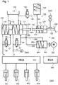
- Fig. 1 shows an example of an electrohydraulic automotive brake system 1000 in preparation for understanding the in Fig. 2 shown embodiment.
- brake system is a dual-circuit brake system with a first brake circuit 10 and a second brake circuit 20.
- the present invention does not depend on the number of brake circuits of the brake system 1000 from.
- the brake system 1000 includes a hydraulic pressure generator assembly 100, which is fluidically coupled to the two brake circuits 10, 20, one with the assembly 100 fluidically coupled simulator circuit 145, a centrally arranged hydraulic fluid reservoir 170, and a hydraulic fluid reservoir 140 and the simulator circuit 145 fluidly coupling fluid path 140 with a valve 132 disposed therein.
- the brake system 1000 further includes a sensor system 2000, 2002 for the quantitative detection of a driver's request (eg detection an actuation travel s and / or an actuation force F on the brake pedal 126) and a hydraulic pressure present in the brake circuits 10, 20, an electronic control unit or an electronic control unit 200 (hereinafter referred to as ECU), a hydraulic control unit 300 (hereinafter referred to as HCU) and in each case with the first brake circuit 10 and the second brake circuit 20 fluidly coupled wheel brakes 401-404.
- the brake system 1000 comprises two return lines 30, 40, each with valves 31 ', 41' arranged therein.
- the return lines 30, 40 are each fluidically coupled to a first end with a corresponding brake circuit 10, 20 and fluidly coupled to the non-pressurized hydraulic fluid reservoir 170 at a second end. Via the return lines 30, 40, a hydraulic pressure built up in the brake circuits can be rapidly reduced (by opening the valves 31 ', 41', which assume a closed valve position in the unactuated state).
- the brake system may include a generator unit for energy recovery (not shown in FIG Fig. 1 ).
- the generator unit is designed to convert kinetic energy back into electrical energy during braking operation.
- the generator unit is connected to at least one wheel in order to convert the rotational movement into electrical energy.
- the generator unit with an energy storage (eg a battery, in Fig. 1 not shown) which stores the recovered electrical energy.
- the HCU 300 comprises a plurality of electrically operable valve groups for hydraulic pressure regulation in the two brake circuits 10, 20. Differing from the in FIG. 1 shown separate formation of HCU 300, the valves 31, 41 and the first valve means 132, the valves 31, 41, 132 may also be integrated into the HCU 300. Implementation examples for the valves or valve groups of the HCU 300 are in connection with the Fig. 2 described in more detail below.
- the ECU 200 is at least designed to drive the electrically actuatable valves of the HCU 300. It is also designed to control the assembly 100. The control takes place on the basis of the sensor signals detected by the sensor system 2000, 2002. The ECU 200 evaluates the sensor signals and generates corresponding ones Control signals for the valves and / or the assembly 100. The ECU 200 includes for this purpose control functions for the HCU 300 and the assembly 100. Alternatively, it is also conceivable that the drive functions for the assembly 100 and the HCU 300 are each organized in separate electronic control subunits and these subunits interact accordingly during braking operation.
- the hydraulic pressure generator assembly 100 comprises a first cylinder-piston device 110, 112, 114, a second cylinder-piston device 260, 262 with an electromechanical actuator 160 acting on the second cylinder-piston device 260, 262 and a pedal interface a third cylinder-piston device 120, 122. Further, the assembly 100 includes a fluid path 268 for fluidly coupling the second cylinder-piston device 260, 262 with the first cylinder-piston device 110, 112, 114 and a power transmission device 150 to optional coupling of the third cylinder-piston device 120, 122 with the first cylinder-piston device 110, 112, 114. According to a variant, the pressureless hydraulic fluid reservoir 170 may be integrated into the assembly 100 for storing hydraulic fluid.
- the present assembly 100 is configured to build up a hydraulic pressure required on the wheel brakes 401-404 solely by actuating the first piston 112, 114 of the first cylinder-piston device 110, 112.
- the actuation of the first piston 112, 114 takes place in a push-through operation of the brake system 1000 fußkraftnot by coupling the first cylinder-piston device 110, 112, 114 with the third cylinder-piston device 120 and in a normal mode (or brake -by-wire operation) of the brake system 1000 fußkraftungenic by hydraulic coupling of the first cylinder-piston device 110, 112, 114 with the second cylinder-piston device 260, 262.
- the brake system 1000 or the assembly 100 is usually located in Normal operation and only goes into a push-through operation when the piston 112, 114 of the first cylinder-piston device 110, 112, 144 are not hydraulically actuated via the second cylinder-piston device 260, 262. This may for example be the case when the electromechanical actuator 160 or its electronic control is not working properly or fails (eg in a vehicle electrical system failure).
- first cylinder-piston device 110, 112, 114 and the second cylinder-piston device 260, 262 fluidically coupled to the first cylinder-piston device 110, 112, 114 will be described.
- the first cylinder-piston device 110, 112, 114 comprises a first piston 112, which is displaceably received in a first cylinder 110 (referred to as primary piston in the following), and a second piston 114, which is displaceably received in the first cylinder 110 (referred to below as a secondary piston or floating piston). Both pistons 112, 114 may each be coupled to a spring device, which are designed to reset the two pistons 112, 114 in the unactuated state to their original position.
- Primary piston 112 and secondary piston 114 are arranged one after the other in the first cylinder 110 (tandem principle) and define three hydraulic chambers 111, 116, 118.
- a first hydraulic chamber 111 is formed by an end face of the primary piston 112 facing away from the hydraulic pressure generating direction (right front side in FIG Fig. 1 , hereinafter referred to as rear side) and a rear side of the primary piston 112 facing the first cylinder bottom defined.
- a second hydraulic chamber 116 is actuated by an end face of the primary piston 112 pointing in the direction of actuation for producing hydraulic pressure (left end face of the primary piston in FIG Fig. 1 ) and by one of the actuating direction for hydraulic pressure generation facing away from the end face of the secondary piston 114 defined.
- a second cylinder bottom defines a second hydraulic chamber 118.
- first hydraulic chamber 111 and the second hydraulic chamber 116 are separated from each other via the slidably received primary piston 112.
- the second hydraulic chambers 116 and the third hydraulic chamber 118 are separated from each other via the slidably received secondary piston 114.
- the second hydraulic chamber 116 is fluidically coupled to the first brake circuit 10 and the third hydraulic chamber 118 to the second brake circuit 20. Further, the second hydraulic chamber 116 and the third hydraulic chamber 118 fluidly communicate in a known manner with the pressureless hydraulic fluid reservoir 170. In this way it is ensured that the second hydraulic chamber 116 and the third hydraulic chamber 118 are always supplied with sufficient hydraulic fluid, so that upon actuation of the primary piston 112 and secondary piston 114, hydraulic fluid may be delivered from the two chambers 116, 118 into the respective brake circuits 10, 20 to build up hydraulic pressure at the wheel brakes 401-404.
- the first hydraulic chamber 111 is fluidically coupled to the second cylinder-piston device 260, 262 via a fluid path 268. However, it is not fluidically coupled to one of the brake circuits 10, 20.
- the first hydraulic chamber 111 serves, in the brake-by-wire braking mode, to take in a volume of hydraulic fluid delivered from the second cylinder-piston device 260, 262 as part of a pressure build-up phase or pressure hold phase, or to absorb it again into the second cylinder during a pressure reduction phase. Piston device 260, 262 deliver.
- the second cylinder-piston device 260, 262 comprises a second piston 262, which is displaceably received in a second cylinder 260.
- the second piston 262 is provided with its end facing the electromechanical actuator 160 (right-hand side in FIG Fig. 1 ) is coupled to the electromechanical actuator 160.
- the second piston 262 further defines, with its front side remote from the electromechanical actuator 160, together with the cylinder 260, a hydraulic chamber 264.
- the hydraulic chamber 264 is fluidically coupled via a fluid path 266 to the centrally arranged hydraulic fluid reservoir 170. This ensures that the hydraulic chamber 264 is always supplied with sufficient hydraulic fluid.
- the hydraulic chamber 264 is also in direct fluidic contact via the fluid path 268 with the first hydraulic chamber 111 of the first cylinder-piston device.
- the second cylinder-piston device 260, 262 has no direct fluidic connection to one of the two brake circuits 10, 20 of the brake system. Thus, no hydraulic fluid from the second cylinder-piston device can be conveyed directly to the wheel brakes 401-404. Rather, the second cylinder-piston device is designed to operate the primary piston 112 (and the secondary piston 114 coupled thereto) hydraulically during braking operation.
- the second piston 262 is actuated via the electromechanical actuator 160.
- the electromechanical actuator 160 is provided to move the second piston 262 in the second cylinder 260 back and forth in response to the drive signals received from the ECU 200. With an advance of the piston (piston 262 moves to the left in Fig. 1 ) is thereby applied by the actuator 160 Actuating force transmitted to the hydraulic fluid in the hydraulic chamber 264. As a result, a hydraulic pressure is generated in the hydraulic chamber 264, which is just the ratio of the applied by the actuator 160 operating force and the effective area of the second piston 262, on which the actuating force acts (effective area of the second piston 262).
- the hydraulic chamber 264 is fluidly coupled to the first chamber 111 of the first cylinder-piston device 110, 112, 114 via the fluid path 268, the hydraulic pressure built up in the hydraulic chamber 264 is transferred to the first chamber 111.
- the hydraulic pressure generated in the second cylinder-piston device 260, 262 thus lies on the rear side of the primary piston 112 as the actuating pressure for the primary piston 112. Due to the displacement of the primary piston 112 in the direction of the second hydraulic chamber 116, the volume of the first hydraulic chamber 111 increases while the volume of the second hydraulic chamber 116 and the third hydraulic chamber 118 of the first cylinder-piston device 110, 112, 114 decreases.
- the increasing volume of the first hydraulic chamber 111 is continuously supplied with hydraulic fluid displaced from the hydraulic chamber 264 of the second cylinder-piston assembly 260, 262 due to the operation of the second piston 262, so that the operating pressure at the back of the primary piston 112 is always maintained.
- the displacement of the primary piston 112 causes the hydraulic pressure in the second and third chambers 112, 114 (and in the brake circuits 10, 20 and wheel brakes 401-404 coupled thereto) to increase steadily.
- the displacement of the primary piston 112 continues until a hydraulic pressure, which corresponds to the actuating pressure in the first hydraulic chamber 111 or in the hydraulic chamber 264 of the second cylinder pistons, has been set in the hydraulic chambers 116, 118 fluidically coupled to the wheel brakes 401-404 Means 260, 262 corresponds.
- the hydraulic pressure at the wheel brakes 401-404 produced by hydraulic actuation of the primary piston corresponds to the actuation pressure generated in the second cylinder-piston device 260, 262.
- each actuation pressure in the hydraulic chamber 264 is transferred lossless to the primary piston 112, so that it is actuated accordingly. If, for example, an actuating pressure is built up by advancing the piston 262, a corresponding displacement of the primary piston 112 will take place due to the acting actuating pressure and a corresponding hydraulic pressure will be built up on the wheel brakes 401-404.
- the primary piston 112 is moved back accordingly and the hydraulic pressure at the wheel brakes 401-404 is correspondingly reduced or reduced.
- the magnitude of the actuation of the primary piston 112 depends on the actuation pressure generated by the electromechanical actuator 160 and the second piston 262. Due to the present serial hydraulic coupling of the first cylinder-piston device 110, 112, 114 with the second cylinder-piston device 260, 262, a hydraulic pressure at the wheel brakes 401-404 can be generated lossless and just as fast as when the electromechanical actuator 160 would be coupled directly to the first primary piston 112 and actuation of the primary piston 112 would be accomplished directly by the electromechanical actuator 160.
- the coupling of the electromechanical actuator 160 to a second cylinder-piston device 260, 262 fluidly coupled to the first cylinder-piston device 110, 112, 114 instead of directly coupling the electromechanical actuator 160 to the first cylinder-piston device 110, 112, 114 also allows a translation of the primary piston 112 to be provided operating force. Because for each desired hydraulic pressure at the wheel brakes (brake pressure), a certain actuating force must be applied to the primary piston 112 and the secondary piston 114, which corresponds to the product of the hydraulic pressure to be generated and an effective piston area of the primary piston 112 on which the hydraulic pressure acts (effective area). The greater the effective area of the primary piston 112, the greater is the actuation force to be applied.
- the effective area of the second piston 262 is selected to be smaller than the effective area of the primary piston 112. In this way, the expended to generate a predetermined hydraulic pressure actuating force on the second cylinder-piston means 260, 262 can be reduced according to the ratio of the two effective surfaces of the first and the second piston. In order to still achieve the predetermined hydraulic pressure in the first cylinder-piston device 110, 112, 114, the second piston 262 only has to cover a longer actuating travel. The increase in the actuation travel is in inverse proportion to the effective areas of the primary piston 112 and the second piston 262.
- a hydraulic force amplification can be achieved, wherein the actuating force applied by the electromechanical actuator 160 is amplified by the ratio of the primary piston 112 predetermined by the two active surfaces.
- an actuating force that is lower by the ratio of the two effective surfaces can be applied to the second piston 262 than to the primary piston 112.
- the engine torque as well as the spindle and bearing forces of the electromechanical actuator can be kept smaller in order to produce a hydraulic pressure predetermined in comparison to an unamplified system.
- the pedal interface includes a third hydraulic cylinder 120 with a third piston 122 slidably received therein. Cylinder 120 and piston 122 in turn define a hydraulic chamber 124 which is fluidly coupled to the simulator circuit 145 of the brake system 1000. Further, the hydraulic chamber 124 is selectively fluidically coupled to the central hydraulic fluid reservoir 170 via a fluid path 140 and an electrically actuatable valve 132 received therein. The optional coupling to the hydraulic fluid reservoir 170 guarantees that the Hydraulic chamber 124 and / or the simulator circuit 145 are always supplied with enough hydraulic fluid.
- the third piston 122 is further provided with a first plunger 125 and a second plunger 123.
- the first plunger 125 is attached at a first end to a brake pedal 126 facing front side of the third piston 122.
- a second end of the second plunger 125 is mechanically coupled to the brake pedal 126.
- a pedal operation ie, a depression of the brake pedal 1266
- the second plunger 123 is attached to an end face of the third piston 122 facing the direction of travel.
- the second plunger 123 is provided to transmit a piston movement to the power transmission device 150. Both plungers may be arranged coaxially with the piston 122.
- the power transmission device 150 is configured to transmit an actuating force applied to the brake pedal to the first cylinder-piston device 110, 112, 114.
- the power transmission device 150 may be formed as a piston rod 151, which is arranged in the assembled state of the assembly 100 between the first cylinder-piston assembly 110, 112, 114 and the third cylinder-piston assembly 120, 122.
- the piston rod 151 may be coupled at one end to the back of the primary piston 112 of the first cylinder-piston assembly 110, 112, 114.
- the piston rod 151 may in this case be arranged coaxially with the primary piston 112 and extend in the direction of the third cylinder-piston device 120, 122.
- the piston rod 151 can be brought with its second end with the second plunger 123 in abutment.
- the second end of the piston rod 151 is not directly coupled to the second plunger 123 but spatially separated by a gap (or gap d) 152 from the second plunger 123.
- This gap 152 exists as long as the brake pedal 126 has not been operated. It also exists upon actuation of the brake pedal 126 in the normal braking mode, since in this case the primary piston 112 and the piston rod 151 coupled thereto are hydraulically actuated by means of the actuating pressure generated in the second cylinder-piston device 260, 262. In this case, the primary piston 112 and the piston rod 151 coupled thereto are sufficiently advanced (shift to the left in FIG Fig.
- the actuator 160 In the emergency operation of the actuator assembly 100, the actuator 160 remains unactuated. Thus, the piston rod 151 is not hydraulically advanced. Upon depression of the brake pedal 126, the (small) gap 152 between the second plunger 123 and the second end of the piston rod 151 can be overcome quickly. The second plunger 123 comes into abutment with the piston rod 151. The piston rod 151 then transmits the depression of the brake pedal 126 caused displacement of the piston 122 in the direction of the piston rod 151 directly to the primary piston 112 of the master cylinder 110 (push-through principle). The primary piston 112 in turn transmits the displacement to the secondary piston 114. By actuating primary piston 112 and secondary piston 114, a hydraulic pressure can then be built up on the wheel brakes 401-404. Thus, the mechanical transmission 150 described herein enables direct mechanical coupling of the primary piston 112 to the third piston 122 of the pedal interface or brake pedal 126 for hydraulic pressure buildup during emergency operation (i.e., when no hydraulic pressure is buildable across the actuator 160
- first cylinder-piston device 110, 112 the first cylinder-piston device 110, 112, 114 and the third cylinder-piston device 120, 122 are arranged spatially one behind the other and substantially coaxial with each other.
- the situation is different with the second cylinder-piston device 260, 262. Although this is hydraulically connected in series with the first cylinder-piston device 110, 112, 114, but depending on the configuration of the first cylinder-piston device 110, 112 and the second cylinder-piston device 260, 262 fluidically connecting fluid path 268 may be arranged arbitrarily.
- the second cylinder-piston device 260, 262 and the thus coupled electromechanical actuator 160 spatially parallel to the first Cylinder-piston device 110, 112, 114 and the third cylinder-piston device 120, 122 may be arranged. In this way, the axial length of the assembly 100 compared to the aforementioned architectures can be further reduced.
- the simulator circuit 145 is fluidically coupled to the third cylinder-piston device 120, 122. It can also be fluidically coupled to the hydraulic fluid reservoir 170 via the fluid path 140 and the electrically actuatable valve 132 arranged therein.
- the simulator circuit 145 includes a hydraulic pressure accumulator 144, which is fluidically coupled to the chamber 124 via a fluid path 141 (and a throttle valve or throttle check valve disposed therein).
- the hydraulic pressure accumulator 144 is realized as a piston-cylinder arrangement, wherein the piston slidably received in the cylinder is biased by a spring.
- the hydraulic fluid delivered from the chamber 124 is directed via the fluid path 141 into the hydraulic accumulator 144.
- the fluid flowing into the hydraulic accumulator 144 displaces the piston biased by the spring.
- the applied for the displacement of the piston force acts as a pedal restoring force on the brake pedal 126 back.
- the hydraulic accumulator 144 generates a back pressure, which acts on the third piston 122 and the brake pedal 126.
- the third piston 122 is coupled to the primary piston 112.
- the pedal reaction is determined by the hydraulic pressure generated by the primary piston. A reaction behavior does not need to be simulated in this case.
- the displaced from the chamber 124 hydraulic fluid can be discharged via the open valve 132 without pressure in the hydraulic fluid reservoir 170.
- FIG. 2 An embodiment of an electrohydraulic vehicle brake system 1000a according to the invention is shown.
- Components of the brake system 1000a, those with those of Fig. 1 shown brake system 1000 are identical or similar in function, are denoted by the same reference numerals.
- the brake system 1000a comprises a hydraulic pressure generator assembly 100, two brake circuits 10, 20 fluidically coupled to the hydraulic pressure generator assembly 100, at the end of which respective wheel brakes 401-404 are fluidically coupled, two return lines 30, 40, which can be assigned to the two brake circuits 10, 20 central hydraulic fluid reservoir (not shown), a simulator circuit 145, fluid path 140 fluidically coupled to simulator circuit 145 and hydraulic fluid reservoir with valves 132, 134, 136 disposed therein, and another fluid path 340 fluidically coupled to simulator circuit 145 and assembly 100 with one therein Valve 330.
- the brake system 1000a includes an electronic control unit, or ECU for short (in Fig. 2 not shown), for driving the assembly 100 and valves of the brake system 1000a and a plurality of electrically operable valves 301-304, which are arranged in the brake circuits 10, 20 and in the return lines 30, 40 and will be described in more detail below.
- ECU electronice control unit
- the hydraulic fluid reservoir 170 and the simulator circuit 145 come in connection with the brake system 1000 in Fig. 1 described functions too. It is in this context to the corresponding description of Fig. 1 directed.
- the assembly 100 includes a first cylinder-piston device 110, 112, 114 for hydraulic pressure generation at the wheel brakes 401-404, a second cylinder-piston device 260, 262 with an electromechanical force acting on the second cylinder-piston device 260, 262 Actuator 160 for generating an actuating pressure for the first cylinder-piston device 110, 112, 114, a second cylinder-piston device 260, 262 with the first cylinder-piston device 110, 112, 114 fluidly coupling fluid path 268 for transmission the actuating pressure on the first cylinder-piston device 110, 112, 114 and a pedal interface with a third cylinder-piston device 120, 122 and a transmission device 123 for direct transmission of a force applied to the brake pedal 126 foot force on the first cylinder-piston device 110, 112, 114.
- the assembly 100a is different from that in FIG Fig. 1 illustrated assembly 100 only in the specific embodiment of the primary piston 112 of the first cylinder-piston device 110, the transmission device 123 for transmitting a foot force in push-through braking operation and in the specific embodiment of the electromechanical actuator 160th
- first cylinder-piston device 110, 112, 114 and the third cylinder-piston device 120, 122 mechanically coupleable to the first cylinder-piston device 110, 112, 114 will be described.
- the structure and function of the first cylinder-piston device 110, 112, 114 and the third cylinder-piston device 120, 122 correspond substantially to the structure and the function of in Fig. 1
- the first cylinder-piston device 110, 112, 114 in turn comprises a primary piston 112 and a secondary piston 114, which in the cylinder 110, the first cylinder piston device 110, 112, 114 and the third cylinder-piston device 120, 122 shown three successively arranged hydraulic chambers 111, 116, 118 define.
- a first hydraulic chamber 111 is fluidly coupled to the second cylinder-piston device via a fluid path 268.
- a second hydraulic chamber 116 is fluidically coupled to the first brake circuit 10 and a second hydraulic chamber 118 is coupled to the second brake circuit 20 of the brake system 1000a.
- a second hydraulic chamber 118 is coupled to the second brake circuit 20 of the brake system 1000a.
- the operation of the first cylinder-piston device 110, 112, 114 is to the corresponding text passages of Fig. 1 directed.
- the first cylinder-piston device 110, 112, 114 and the third cylinder-piston device 120, 122 are arranged in the mounted state in succession.
- the third cylinder-piston device 120, 122 is in this case arranged coaxially with the first cylinder-piston device 110, 112, 114.
- the third piston 122 of the third cylinder-piston device 120, 122 is in turn mechanically coupled to a first plunger 125 and to a second plunger 123.
- the first plunger 125 is coupled in a known manner to the brake pedal 126 for transmitting a pedaling action to the third piston 122.
- the second plunger 123 is coupled at one end to the third piston 122.
- the third cylinder 120 has for this purpose a bore on the cylinder bottom for the passage of the plunger 123. The hole is going through Sealing elements sealed so that no hydraulic fluid escape from the chamber 123.
- the first cylinder 110 of the first cylinder-piston device 110, 112, 114 at its front side facing the third cylinder-piston device 120, 122 facing a coaxially with respect to the first cylinder 110 and inwardly formed tubular shaft 127 for receiving the from the third cylinder-piston device 120, 126 outstanding ram portion 123 on.
- the first plunger portion 123 projects into the well 127 of the first cylinder-piston device 110, 112, 114 and is spatially separated from the primary piston 112 only by a narrow gap 152.
- the primary piston 112 knows in the Fig. 2 shown embodiment at its rear side on a U-shaped profile, wherein the shaft 127 projects into the U-shaped recess of the primary piston 112.
- the hydraulic chamber 111 is defined by the piston rear side and the inner wall of the first cylinder 110 and the shaft 127.
- the plunger 123 serves as a power transmission device for transmitting a foot force to the primary piston 112 in a push-through operation.
- push-through operation no electro-hydraulic actuation of the primary piston 112 takes place.
- the gap 152 between the plunger 123 and the back of the primary piston 112 can be overcome quickly upon depression of the pedal 126.
- the second plunger 123 comes into abutment with the primary piston 112 and transmits any further movement directly to the primary piston 112, whereby a hydraulic pressure in the first cylinder-piston device 110, 112, 114 can be constructed.
- brake-by-wire operation the actuation of the primary piston 112 is effected by the actuating pressure built up in the second cylinder-piston device 260, 262.
- the hydraulic actuation of the primary piston 112 causes the primary piston 112 ahead of the plunger 123 sufficiently, so that in brake-by-wire operation by depressing the brake pedal 126, the gap 152 can not be overcome. In this way, it can be guaranteed that the hydraulic pressure is built up or adjusted exclusively by means of the second cylinder-piston device 260, 262 during brake-by-wire operation.
- the second cylinder-piston device 260, 262 and the electromechanical actuator 160 coupled to the second cylinder-piston device 260, 262 will now be described.
- the electromechanical actuator 160 comprises an electric motor 161 and a transmission 162, 163 coupled to the electric motor 161 for transmitting the motor movement to the second piston 262 of the second cylinder-piston device 260, 262.
- the transmission is an arrangement of a rotatably mounted Nut 163 and one with the nut 163 (eg via rolling elements such as balls) in engagement and axially movable spindle 162.
- rack gears or other types of gears can be used.
- the electric motor 161 in the present embodiment has a cylindrical shape and extends concentrically with the gear 162, 163. More specifically, the electric motor 161 is disposed radially outward of the gear 162, 163. A rotor (not shown) of the electric motor 161 is rotatably coupled to the gear nut 163 to rotate it. A rotational movement of the nut 163 is transmitted to the spindle 162 such that an axial displacement of the spindle 162 results. In the Fig. 1 left end side of the spindle 162 is mechanically coupled or coupled to the second piston 262. An axial displacement of the spindle 162 thus transmits directly to the second piston 162, wherein this is displaced in the second cylinder 260 along the cylinder 260.
- the electromechanical actuator 160 is thus adapted to build an operating pressure for the primary piston 112 of the first cylinder-piston device 110, 112, 114 independently (ie foot power independent) via the piston 262.
- the amount of pressure build-up may be set via at least one driving value of the ECU 200 which includes information on how much the actuator 160 is to be operated (or the spindle 162 is to be displaced in the hydraulic pressure generating direction).
- the drive value can be determined on the basis of a sensor coupled to the brake pedal 126 or the pedal interface (eg by means of displacement and / or force sensors 2002).
- the actuating pressure built up in the second chamber 264 is transmitted via the fluid path 268 to the primary piston 112 of the first cylinder-piston device 110, 112, 114.
- the primary piston 112 and the secondary piston 114 coupled thereto are actuated for so long due to the applied hydraulic pressure (ie to the left in FIG Fig. 2 shifted) until the hydraulic pressure generated in the hydraulic chambers 116 and 118 (and thus applied to the brakes 401-404 brake pressure) corresponds to the applied in the first hydraulic chamber 111 operating pressure.
- a hydraulic pressure at the wheel brakes 401-404 can be generated in the same way as when the electromechanical actuator is directly connected to the first cylinder piston Device 110, 112, 114 would be coupled.
- the serial arrangement of the two cylinder-piston devices allows the realization of a hydraulic power boost as in Fig. 1 described in connection with the example.
- the brake system 1000a (or a hydraulic control unit associated with the brake apply system 1000a, or HCU) includes a first group of four electrically operable valves 301-304, with each wheel brake 401-404 associated with exactly one valve 301-304.
- the valve 301-304 associated with each wheel brake 401-404 is configured to hydraulically couple or hydraulically lock the wheel brake 401-404, depending on the switching state of the valve 301-304, from the first cylinder piston device 110, 112, 114 decouple.
- the timing of the individual valves 301-304 takes place via the ECU.
- valves 301-304 may be actuated by the ECU in a time division multiplexed manner.
- each valve 301-304 (and thus each wheel brake 401-404) can be assigned at least one time slot for a valve actuation. This assignment does not exclude that individual valves 301-304 are kept open or closed over several time slots or more than two valves are open at the same time.
- a service brake when the assembly 100 is in normal operation
- hydraulic pressure at the wheel brakes 401-404 wheel individually or wheel groups individually for the purpose of vehicle dynamics control (ie, for example, in the ABS and / or ASR and / or ESP control mode).
- the brake system 1000a further comprises a second group of four electrically actuatable valves 311-314, wherein each wheel brake 401-404 is associated with exactly one valve 311-314.
- the valves 311-314 are in this case arranged in the return lines of the wheel brakes 401-404, wherein the return lines of the wheel brakes 401-404 of a brake circuit 10, 20 at the valve outlet of the valves 311-314 in the brake circuit 10, 20 associated return line 30, 40 open , The return lines 30, 40 open into the hydraulic fluid reservoir 170.
- the two valves 311-314 take in the unactuated state in each case a closed valve position, so that no hydraulic fluid from the respective wheel brakes 401-404 can flow into the pressureless hydraulic fluid reservoir 170.
- a driving dynamics control eg ABS and / or ASR and ESP control operation
- they can be switched to an open valve position by means of electrical control of the ECU 200 in order to discharge hydraulic fluid via the respective brake circuits 10, 20 into the pressureless hydraulic fluid reservoir 170 in a controlled manner allow.
- the two brake circuits 10, 20 and the two brake circuits 10, 20 associated return lines 30, 40 may each be fluidly coupled to each other via a check valve 31, 41.
- the check valves 31, 41 are in this case of the first cylinder-piston device 110, 112, 114 in front of the valves 301-304, 311-314 in a first brake circuit 10 with the first return line 40 and in a second brake circuit 20th arranged with the second return line 30 coupling fluid path.
- the two check valves 31, 41 are arranged such that they do not allow any hydraulic fluid from the respective brake circuit 10, 20 to flow into the respective return line 30, 40.
- hydraulic fluid can flow directly from the hydraulic fluid reservoir 170 into the two chambers 116, 118 of the first cylinder-piston device 110, 112, 114 via the check valves.
- This may for example be the case when the primary piston 112 and the secondary piston 114 are in the return stroke and in the chambers 116, 118, a negative pressure. In this way it can be ensured that the chambers 116, 118 of the first cylinder-piston device 110 are supplied with sufficient hydraulic fluid even after actuation.
- valves 31, 41 301-304, 311-314 After describing the valves 31, 41 301-304, 311-314, the description of the valves 132, 134, 136 arranged in the fluid path 140 will now be given.
- valves 134, 136 are arranged next to the electrically actuated valve 132 next to the electrically actuated valve 132 .
- These two valves 134, 136 are designed as pressure-controlled pressure relief valves. They are intended to additionally feed a hydraulic fluid displaced in the push-through mode of the brake system 1000a from the third cylinder-piston device 120, 122 into at least one brake circuit 10, 20 of the brake system 1000a.
- the additionally introduced Hydraulic fluid in the brake circuits 10, 20 may help to quickly overcome a clearance present on the wheel brakes 401-404 in push-through operation.
- the fluid path 140 is divided after the electrically operable valve 132 in a first branch 140a and in a second branch 140b, wherein the first branch 140a opens into the first brake circuit 10 and the second branch 140b in the pressureless hydraulic fluid reservoir 170 or in the non-pressurized Hydraulic fluid reservoir 170 leading return line 40 opens.
- the first pressure relief valve 134 is arranged in the first branch 140 a of the second fluid path 140.
- the second pressure relief valve 136 is disposed in the second branch 140 b of the second fluid path 140.
- valve 132 In a push-through braking operation, the valve 132 remains unactuated and thus in an open valve position. A displaced from the hydraulic cylinder 120 hydraulic fluid in push-through operation can then flow through the open valve 132 to the downstream arranged first and second pressure relief valves 134, 136 and via these valves (depending on the hydraulic pressure in the first brake circuit 10) either in the first brake circuit 10 or drain into the hydraulic fluid reservoir 170.
- the first pressure relief valve 134 is in the form of a check valve.
- the check valve 134 is arranged such that, when the valve position is open, only hydraulic fluid can flow from the hydraulic cylinder 120 into the first brake circuit 10, but in the opposite direction completely blocks it.
- the first check valve 134 is formed as a spring-loaded check valve which is limited to a low overflow pressure (e.g., 0.3 bar).
- hydraulic fluid from the third hydraulic cylinder 120 via the valve 132 (this is open in push-through operation) and the downstream check valve 134 in the first brake circuit 10 (and via the first fluid-coupled first cylinder piston Means 110, 112, 114 also in the second brake circuit 20) are always fed when the hydraulic pressure generated by displacement of the third piston 122 in the third cylinder 120 is higher than the Ventilüberströmtik and applied to the valve outlet of the check valve 134 hydraulic pressure.
- the second pressure relief valve 136 is designed as a pressure-controlled pressure relief valve 136, which upon reaching a predetermined pressure in the first cylinder-piston device 110, 112, 114 or in the first brake circuit 10 (for example, 10 bar) switches from a closed state to an open state.
- the second pressure relief valve 136 is fluidically coupled to the first brake circuit 10 for control purposes (see dashed line on the valve 136 in FIG Fig. 2 ).
- the pressure relief valve 136 switches to an open valve position.
- the hydraulic fluid accumulated during the push-through operation in the fluid path 140 and at the valve inlets of the valves 134, 136 can then flow off via the second partial path 140b into the pressureless hydraulic fluid reservoir 170 without pressure.
- the second pressure relief valve 136 thus determines how long hydraulic fluid from the third cylinder-piston device 120, 122 is fed into the brake circuits 10, 20.
- the valve 136 prevents unnecessary accumulation of hydraulic fluid at the first check valve 134 when, for example, during the push-through phase of the pressure generated in the first cylinder-piston device 110, 112, 114 is at the pressure generated in the third cylinder 120 approaches or even exceeds.
- the fluid path 340 terminates at one end in the first hydraulic chamber 111 of the first cylinder-piston device 110, 112, 114 and at a second end in the hydraulic chamber 124 of the third cylinder-piston device 120, 122.
- the fluid path 340 thus allows a optionally fluidic coupling of the third cylinder-piston device 120, 122 and the simulator circuit 145 coupled thereto with the first hydraulic chamber 111 and the second cylinder-piston device 260, 262 coupled thereto.
- This fluidic coupling can be used to implement automatic test methods or an automatic test Venting method for the simulator circuit 145 are used, as will be explained briefly below.
- the electrically actuatable valve 330 arranged in the fluid path 340 assumes a closed valve position in the unactuated (de-energized) state.
- the valve 330 remains closed during normal operation and during push-through operation of the assembly 100.
- hydraulic fluid can not pass from the second cylinder-piston device 260, 262 via the fluid path 340 into the third cylinder-piston device 120, 122 or into the simulatory circuit 145 fluidically coupled thereto.
- fluid coupling of the second cylinder-piston device 260, 262 with the third cylinder-piston device 120, 122 and the simulator circuit 145 may be desired as part of an automatic test procedure or automatic ventilation process for the simulator circuit 145.
- hydraulic fluid may be delivered from the chamber 264 of the second cylinder piston assembly 260, 262 directly into the third cylinder and piston assembly 120, 122 and the simulator circuit 145 coupled thereto.
- the delivered hydraulic fluid flows via the fluid path 268, via the chamber 111, the released fluid path 340, the chamber 124 and the fluid path 141 into the hydraulic pressure accumulator 144 of the simulator circuit 145.
- the hydraulic accumulator 144 generates a back pressure.
- the displaced hydraulic fluid may be measured in response to a pressure increase in the chamber 264.
- the hydraulic fluid volume displaced during the actuator actuation can be determined from a detection of an actuation movement of the electromechanical actuator 160 (eg, from the engine position and the known transmission ratio of the transmission).
- the pressure increase can be determined via a pressure sensor in the hydraulic chamber 264 or in the simulator circuit (not shown in FIG Fig. 1 ).
- the obtained pressure-volume characteristic can be compared with a stored pressure-volume characteristic and from this a statement about the degree of deaeration of the simulator circuit 145 can be made. Because with air polluted fluid is compressible and shows a different compared to a pure fluid other pressure-volume characteristics.
- valves 301-304 may be coupled to the wheel brakes 401 during the test procedure -404 can be switched to a closed valve state.
- the hydraulic fluid displaced into the simulator circuit 145 can be discharged via the fluid path 140 into the hydraulic fluid reservoir 170 subsequent to the test procedure.
- only the electrically actuatable valve 132 arranged in the fluid path 140 has to be switched to an open valve position again.
- the brake systems described here 1000, 1000a and hydraulic pressure generator assemblies 100, 100a are designed for the realization of a brake-by-wire braking operation and a push-through braking operation.
- the hydraulic pressure generator 100, 100a described here is also designed to implement an automatic test method and a venting method of the simulator circuit of the brake system 1000, 1000a.
- hydraulic pressure is built up on the wheel brakes 401-404 solely via the first cylinder-piston device 110, 112, 114.
- the first cylinder-piston device 110, 112, 114 thus corresponds functionally to a master brake cylinder of the vehicle brake system.
- the actuation of the at least one first piston of the first cylinder-piston device 110, 112, 114 takes place hydraulically via the second cylinder-piston device 260, 262 in brake-by-wire operation
- the hydraulic actuation described here has the advantage that the electromechanical actuator does not have to be mechanically coupled directly to the first cylinder-piston device 110, 112, 114. In this way, the structure of the assembly 100 can be further simplified. In particular, by parallel arrangement of the first cylinder-piston device 110, 112, 114 and the second cylinder-piston device 260, 262, the overall length of the assembly 100, 100a can be shortened.
- a hydraulic power boost can be realized, whereby the operating force to be applied by the electromechanical actuator 160 can be further reduced. It can thus be used in comparison to the above-mentioned Bremsanalgen less powerful electromechanical actuators to produce a required hydraulic pressure during a brake-by-wire braking operation.
Description
- Die vorliegende Offenbarung betrifft eine elektrohydraulische Kraftfahrzeug-Bremsanlage.
- Moderne Kraftfahrzeug-Bremsanlagen arbeiten nach dem "Brake-by-Wire"-Prinzip. Das bedeutet, dass ein Hydraulikdruck an den Radbremsen fußkraftunabhängig über einen Hydraulikdruckerzeuger aufgebaut wird. Derartige Bremsanlagen umfassen, neben dem Hydraulikdruckerzeuger, in der Regel eine Bremspedalschnittstelle mit einer Sensorik zur Detektion einer Betätigung eines Bremspedals, eine mit der Bremspedalschnittstelle gekoppelte Simulatoreinrichtung zur Simulation eines realistischen Pedalrückwirkverhaltens und eine Vielzahl von Hydraulikventilen.
- Brake-by-Wire-Bremsanlagen bringen mehrere Vorteile. Beispielsweise sind sie in hervorragender Weise zum Einbau von Energierückgewinnungssystemen geeignet. Ferner kann durch derartige Bremsanlagen ein radindividueller Bremsdruckaufbau besser gesteuert und Fahrdynamikregelungsprogramme (z. B. ABS-, ASR-, ESP-Programme) besser integriert werden.
- Beispiele für die Realisierung von Brake-by-Wire-Bremsanlagen sind aus der
WO 2012/062393 A1 und derWO 2012/152352 A1 bekannt. Die dort gelehrten Hydraulikdruckerzeuger umfassen eine Zylinder-Kolben-Einrichtung zur Hydraulikdruckerzeugung und einen auf den Kolben der Zylinder-Kolben-Einrichtung einwirkenden elektromechanischen Aktuator. Der elektromechanische Aktuator ist der Zylinder-Kolben-Einrichtung nachgeordnet und mit dem Kolben der Zylinder-Kolben-Einrichtung direkt gekoppelt. Der Kolben kann so über den Aktuator unmittelbar betätigt werden, wodurch ein Hydraulikdruck an den Radbremsen fußkraftunabhängig aufgebaut werden kann. - Ferner ist die Zylinder-Kolben-Einrichtung über eine Kraftübertragungseinrichtung mit einer der Zylinder-Kolben-Einrichtung und dem elektromechanischen Aktuator nachgeordneten Pedalschnittstelle koppelbar. In einem Notbetrieb der Bremsanlage (z.B. bei Ausfall des elektromechanischen Aktuators oder dessen Ansteuerung) ermöglicht die Kraftübertragungseinrichtung eine mechanische Kopplung der Zylinder-Kolben-Einrichtung mit der Bremspedalschnittstelle, um eine Betätigung des Kolbens der Zylinder-Kolben-Einrichtung mittels der an der Pedalschnittstelle anliegenden Fußkraft zu ermöglichen (Push-Through-Betrieb).
Die serielle Anordnung von Zylinder-Kolben-Einrichtung, elektromechanischen Aktuator und von Pedalschnittstelle führt in manchen Realisierungen zu einer verhältnismäßig langen axialen Ausdehnung der dadurch entstehenden Baugruppe. Entsprechend große Einbauräume müssen in den Kraftfahrzeugen bereitgestellt werden. Hydraulikdruckerzeuger mit langer axialer Ausdehnung können ferner die Crashsicherheit eines Fahrzeuges negativ beeinflussen. Auch erfordert die in derWO 2012/062393 A1 und derWO 2012/152352 A1 beschriebene Hydraulikdruckerzeuger-Architektur den Einbau leistungsfähiger Aktuatoren, welche genügend hohe Kolbenbetätigungskräfte aufbringen können, um die erforderlichen Hydraulikdrücke im Brake-by-Wire-Bremsbetrieb zu erzeugen.
Eine Bremsanlage gemäß dem Oberbegriff des unabhängigen Anspruchs 1 ist aus derDE 10 2011 085 273 A1 bekannt. Nachteilig bei dieser Bremsanlage ist eine schwierige Entlüftung des Simulatorkreises. - Aufgabe ist es, eine Kraftfahrzeug-Bremsanlage anzugeben, welche eines oder mehrere der oben genannten Probleme oder andere Nachteile bekannter Bremsanlagen-Architekturen überwindet.
Gemäß der Erfindung wird eine Elektrohydraulische Kraftfahrzeug-Bremsanlage gemäß den Merkmalen des unabhängigen Vorrichtungsanspruchs bereitgestellt mit einer mit wenigstens einer Radbremse der Bremsanlage fluidisch koppelbaren ersten Zylinder-Kolben-Einrichtung zur Hydraulikdruckerzeugung an der wenigstens einen Radbremse, wobei die erste Zylinder-Kolben-Einrichtung wenigstens einen ersten Kolben umfasst, mit einer zweiten Zylinder-Kolben-Einrichtung, die wenigstens einen zweiten Kolben umfasst, und mit einen auf den zweiten Kolben der zweiten Zylinder-Kolben-Einrichtung einwirkenden elektromechanischen Aktuator, wobei die zweite Zylinder-Kolben-Einrichtung ausgangsseitig mit dem wenigstens einen ersten Kolben der ersten Zylinder-Kolben-Einrichtung fluidisch gekoppelt oder koppelbar ist, um einen bei Betätigung des elektromechanischen Aktuators in der zweiten Zylinder-Kolben-Einrichtung erzeugten Hydraulikdruck für eine Betätigung des wenigstens einen ersten Kolbens der ersten Zylinder-Kolben-Einrichtung bereitzustellen. - Die Hydraulikdruckerzeugung in der wenigstens einen Radbremse kann in einer Variante allein durch die erste Zylinder-Kolben-Einrichtung erfolgen. Beispielsweise kann die erste Zylinder-Kolben-Einrichtung als einzige druckerzeugende Einheit für die Radbremsen vorgesehen sein. Diese Einheit kann sowohl in einem Push-Through-Betrieb als auch in einem Brake-by-Wire-Betrieb der elektrohydraulischen Kraftfahrzeug-Bremsanlage einen erforderlichen Hydraulikdruck (Bremsdruck) an den Radbremsen erzeugen.
- Der Hydraulikdruck kann durch Betätigung (z.B. Vorbewegung und/oder Rückbewegung) des wenigstens einen ersten Kolbens im ersten Zylinder erzeugt werden. Die Stärke der Verschiebung des wenigstens einen ersten Kolbens (also das Ausmaß der Kolbenbetätigung) kann hierbei ein Maß für die Stärke des erzeugten Hydraulikdrucks an den Radbremsen sein. Im Push-Through-Betrieb erfolgt die Betätigung des wenigstens einen ersten Kolbens fußkraftabhängig. Im Brake-by-Wire-Betrieb der Bremsanlage erfolgt die Betätigung des ersten Kolbens fußkraftunabhängig mit Hilfe des elektromechanischen Aktuators.
- Die elektrohydraulische Bremsanlage umfasst ferner eine mit einem Bremspedal koppelbare Pedalschnittstelle mit einer dritten Zylinder-Kolben-Einrichtung, welche mit der ersten Zylinder-Kolben-Einrichtung zur Hydraulikdruckerzeugung wahlweise koppelbar ist. Im Push-Through-Betrieb der Bremsanlage kann die dritte Zylinder-Kolben-Einrichtung mit der ersten Zylinder-Kolben-Einrichtung gekoppelt sein. Hingegen kann im Brake-by-Wire-Betrieb der Bremsanlage die dritte Zylinder-Kolben-Einrichtung von der ersten Zylinder-Kolben-Einrichtung entkoppelt sein. Die Kopplung kann hierbei mechanisch erfolgen. Beispielsweise kann die Bremsanlage eine mechanische Koppeleinrichtung (oder Kraftübertragungseinrichtung) umfassen, welche dazu ausgebildet ist, den ersten Kolben der ersten Zylinder-Kolben-Einrichtung mit dem dritten Kolben der dritten Zylinder-Kolben-Einrichtung mechanisch zu koppeln.
- Der dritte Kolben der dritten Zylinder-Kolben-Einrichtung ist mit dem Bremspedal gekoppelt. Auf diese Weise kann in einer Variante eine Bremspedalbetätigung (z.B. ein Niederdrücken oder eine Rückbewegen des Bremspedals) und insbesondere die am Bremspedal aufgebrachte Betätigungskraft direkt auf den ersten Kolben übertragen werden. Somit kann im Push-Through-Betrieb der Bremsanlage ein Hydraulikdruck an den mit der ersten Zylinder-Kolben-Einrichtung fluidisch gekoppelten Radbremsen direkt über die am Bremspedal anliegende Fußkraft aufgebaut werden.
- Die zweite Zylinder-Kolben-Einrichtung kann dazu vorgesehen sein, in einem Brake-by-Wire-Betrieb der Bremsanlage einen Hydraulikdruck (Betätigungsdruck) zur hydraulischen Betätigung des ersten Kolbens der ersten Zylinder-Kolben-Einrichtung bereitzustellen. Die Stärke des bereitgestellten Betätigungsdrucks legt den Grad der Betätigung des ersten Kolbens fest (und somit den erzeugten Hydraulikdruck an den Radbremsen). Die Bereitstellung des Betätigungsdrucks kann von einem erfassten Bremswunsch abhängen (z.B. zu diesem proportional sein) oder von den Befehlen eines Fahrdynamikregelungsprogramms. Der Bremswunsch kann durch eine Sensorik am Bremspedal oder in der Pedalschnittstelle erfasst werden und von einer elektronischen Steuereinheit der Bremsanlage in entsprechende Betätigungssignale für den elektromechanischen Aktuator umgewandelt werden. Der Bremswunsch kann beispielsweise durch Erfassen eines Bremspedalweges und/oder einer auf das Bremspedal einwirkenden Betätigungskraft bestimmt werden. Das Fahrdynamikregelungsprogramm, wie beispielsweise ein Antiblockiersystem (ABS), eine Antriebsschlupfregelung (ASR), ein elektronischen Stabilitätsprogramm (ESP), auch als Fahrzeugstabilitätsregelung (Vehicle Stability Control, VSC) bezeichnet, oder ein Abstandsregeltempomat (ACC), kann in der elektronischen Steuereinheit hinterlegt sein. Es kann auf Basis erfasster, auf einen Fahrzustand des Fahrzeugs hinweisender Sensordaten Befehle für den elektromechanischen Aktuator ausgeben.
- In Abhängigkeit der Betätigungssignale oder Befehle kann der elektromechanische Aktuator den zweiten Kolben bewegen und so einen hydraulischen Betätigungsdruck für den wenigstens einen ersten Kolben erzeugen. Die Erzeugung des Betätigungsdrucks kann hierbei nicht bloß auf die Erzeugung eines Soll-Druckwertes beschränkt sein, um die Stärke der Betätigung des ersten Kolbens festzulegen. Vielmehr kann über entsprechende Ansteuerung des elektromechanischen Aktuators auch die Zeitdauer und/oder die Geschwindigkeit der Betätigung des zweiten Kolbens festgelegt werden. Somit kann auch die Geschwindigkeit und/oder die Zeitdauer der Betätigung des wenigstens einen ersten Kolbens allein über den bereitgestellten Betätigungsdruck (und somit fußkraftunabhängig) festgelegt werden. Durch entsprechende zeitliche Regelung des in der zweiten Zylinder-Kolben-Einrichtung bereitgestellten Betätigungsdruckes kann die hydraulische Betätigung des ersten Kolbens zeitlich gesteuert werden. Es können so beliebige Hydraulikdruckaufbau-, Hydraulikdruckhalte- und/oder Hydraulikdruckabbau-Phasen realisiert werden.
Der erste Kolben der ersten Zylinder-Kolben-Einrichtung und die zweite Zylinder-Kolben-Einrichtung sind über einen Fluidpfad der Bremsanlage miteinander fluidisch gekoppelt. Der erste Kolben und der zweite Kolben können über den Fluidpfad fluidisch in Serie geschaltet sein. Ein bei Betätigung des zweiten Kolbens aus der zweiten Zylinder-Kolben-Einrichtung verdrängtes Hydraulikfluid kann über den Fluidpfad zum ersten Kolben der ersten Zylinder-Kolben-Einrichtung gelangen, wodurch dieser betätigt wird. Eine mechanische Betätigung des zweiten Kolbens kann somit in eine hydraulische Betätigung des ersten Kolbens umgewandelt werden. Da das im Fluidpfad und in der zweiten Zylinder-Kolben-Einrichtung befindliche Hydraulikfluid nicht komprimierbar ist, wird jede elektromechanische Betätigung des zweiten Kolbens in eine entsprechende hydraulische Betätigung des ersten Kolbens verlustfrei übertragen. Insbesondere kann der am betätigten zweiten Kolben anliegende Betätigungsdruck dem am ersten Kolben anliegenden Betätigungsdruck entsprechen.
Die erste Zylinder-Kolben-Einrichtung und die zweite Zylinder-Kolben-Einrichtung können derart ausgestaltet sein, dass eine Wirkfläche des wenigstens einen ersten Kolbens und eine Wirkfläche des zweiten Kolbens, auf denen jeweils der erzeugte Hydraulikdruck wirkt, in einem vorgegebenen Verhältnis zueinander stehen. Beispielsweise können der erste Kolben und der zweite Kolben dieselbe Wirkfläche aufweisen oder aber der zweite Kolben eine kleinere oder eine größere Wirkfläche als der erste Kolben aufweisen. Über die Abmessungen der Wirkflächen des ersten Kolbens und des zweiten Kolbens kann eine Übersetzung für die auf den ersten Kolben und den zweiten Kolben einwirkenden Betätigungskräfte festgelegt werden. Denn durch die serielle Kopplung des wenigstens einen ersten Kolbens mit dem zweiten Kolben kann auf beide Kolben der in der zweiten Zylinder-Kolben-Einrichtung durch Verschiebung des zweiten Kolbens erzeugte Hydraulikdruck wirken. Die jeweils effektiv am ersten Kolben und am zweiten Kolben anliegende oder aufzubringende Betätigungskraft kann sich dann gerade aus dem Produkt des erzeugten Betätigungsdrucks und der jeweiligen Kolbenfläche ergeben, auf die der Betätigungsdruck wirkt.
Gemäß einer Variante kann die Wirkfläche des zweiten Kolbens (oder der Kolbendurchmesser) gegenüber der Wirkfläche des ersten Kolbens kleiner ausgebildet sein. In diesem Fall kann die bei einem erzeugten Hydraulikdruck am ersten Zylinder anliegende Betätigungskraft um einem aus dem Verhältnis der beiden Wirkflächen des ersten und des zweiten Kolbens berechenbaren Faktor größer sein als die am zweiten Kolben anliegende oder aufzubringende Betätigungskraft. Beispielsweise kann durch die serielle Schaltung eines größeren ersten Kolbens mit einem kleineren zweiten Kolben eine hydraulische Kraftverstärkung erreicht werden. Um einen bestimmten Hydraulikdruck an den Radbremsen aufzubauen, ist am zweiten Kolben lediglich eine Betätigungskraft aufzuwenden, die gerade um den Faktor des Wirkflächenverhältnisses kleiner ist als die am ersten Kolben aufzuwendende Betätigungskraft. Durch die hydraulische Kraftverstärkung kann so das Motormoment sowie die Spindel- und Lagerkräfte des elektromechanischen Aktuators kleiner gehalten werden, um einen im Vergleich zu einem unverstärkten System vorgegebenen Hydraulikdruck zu erzeugen. - Die erste Zylinder-Kolben-Einrichtung weist wenigstens zwei durch den ersten Zylinder und den im ersten Zylinder verschiebbar aufgenommenen wenigstens einen ersten Kolben definierte Hydraulikkammern auf. Eine erste Kammer kann durch eine erste Stirnseite des ersten Kolbens und dem Zylinder definiert sein. Eine zweite Kammer kann durch eine zweite, der ersten Stirnseite gegenüberliegende, Stirnseite des ersten Kolbens und dem Zylinder definiert sein. Die erste Kammer ist mit der zweiten Zylinder-Kolben-Einrichtung fluidisch gekoppelt. Ferner ist die wenigstens eine zweite Hydraulikkammer mit wenigstens einem Bremskreis der Bremsanlage fluidisch koppelbar. Die erste Kammer kann dazu ausgelegt sein, das aus der zweiten Zylinder-Kolben-Einrichtung verdrängte Hydraulikfluid aufzunehmen. Dadurch kann der erste Kolben in Richtung der zweiten Hydraulikkammer verschoben werden, wodurch das in der zweiten Hydraulikkammer aufgenommene Hydraulikfluid in die Bremskreise verschoben werden kann. Auf diese Weise kann im Brake-by-Wire-Betrieb der erste Kolben hydraulisch betätigt werden und über die zweite Kammer ein entsprechender Hydraulikdruck an den Radbremsen aufgebaut werden.
Gemäß einer Ausgestaltung kann die wenigstens eine zweite Kammer zwei Hydraulikkammern umfassen, wobei die zwei Hydraulikkammern jeweils mit einem Bremskreis der Bremsanlage fluidisch gekoppelt oder koppelbar sind. Die zwei Hydraulikkammern können in der ersten Zylinder-Kolben-Einrichtung nacheinander angeordnet sein (Anordnung der Hydraulikkammern nach dem Tandem-Prinzip).
Die dritte Zylinder-Kolben-Einrichtung ist ferner mit der zweiten Zylinder-Kolben-Einrichtung wahlweise fluidisch koppelbar. Die wahlweise fluidische Kopplung kann über einen Fluidpfad und ein darin aufgenommenes betätigbares
Ventil erfolgen. Der Fluidpfad koppelt die dritte Zylinder-Kolben-Einrichtung mit der mit der zweiten Zylinder-Kolben-Einrichtung fluidisch gekoppelten ersten Kammer der ersten Zylinder-Kolben-Einrichtung wahlweise fluidisch. Es ist alternativ hierzu auch denkbar, dass die dritte Zylinder-Kolben-Einrichtung und die erste Zylinder-Kolben-Einrichtung über den Fluidpfad direkt fluidisch koppelbar sind. Im Bremsbetrieb (Push-Through-Betrieb oder Brake-by-Wire-Betrieb) kann die dritte Zylinder-Kolben-Einrichtung von der zweiten Zylinder-Kolben-Einrichtung fluidisch entkoppelt bleiben. Im Rahmen einer automatischen Entlüftung der Pedalschnittstelle oder eines mit der Pedalschnittstelle gekoppelten Simulatorkreis kann die dritte Zylinder-Kolben-Einrichtung von der zweiten Zylinder-Kolben-Einrichtung fluidisch gekoppelt werden. Es kann dann Hydraulikfluid von der zweiten Zylinder-Kolben-Einrichtung in die Pedalschnittstelle gefördert werden, um diese zu entlüften. - Die erste Zylinder-Kolben-Einrichtung und die dritte Zylinder-Kolben-Einrichtung der Bremsanlage können im montierten Zustand räumlich nacheinander (seriell) angeordnet sein und beispielsweise eine separat handhabbare Baugruppe bilden. Die dem Bremspedal zuordenbare dritte Zylinder-Kolben-Einrichtung kann hierbei vom Bremspedal aus betrachtet vor der ersten Zylinder-Kolben-Einrichtung angeordnet sein. Die dritte Zylinder-Kolben-Einrichtung und die erste Zylinder-Kolben-Einrichtung können koaxial zueinander angeordnet sein.
- Ferner können die erste Zylinder-Kolben-Einrichtung und die zweite Zylinder-Kolben-Einrichtung räumlich im Wesentlichen parallel zueinander angeordnet sein und beispielsweise eine separat handhabbare Baugruppe bilden. Mit anderen Worten kann die nacheinander angeordnete erste und dritte Zylinder-Kolben-Einrichtung im Wesentlichen parallel zur zweiten Zylinder-Kolben-Einrichtung angeordnet sein. Auf diese Weise kann die axiale Ausdehnung der Hydraulikdruckerzeuger-Komponenten (also erste, zweite und dritte Zylinder-Kolben-Einrichtung) weiter reduziert werden.
- Die elektrohydraulische Bremsanlage kann ferner ein Steuergerät oder ein Steuergerätesystem zur elektrischen Ansteuerung des elektromechanischen Aktuators im Brake-by-Wire Betrieb umfassen. Das elektrische Steuergerät oder Steuergerätesystem kann dazu ausgelegt sein, ein auf einen Bremswunsch eines Fahrers und/oder auf einen Fahrzustand des Kraftfahrzeuges hinweisende Messgrößen auszuwerten und entsprechende Ansteuerbefehle für den Aktuator auszugeben. Basierend auf den ausgewerteten Sensorsignalen kann das elektrische Steuergerät oder Steuergerätesystem den elektromechanischen Aktuator entsprechend ansteuern, um einen Betätigungsdruck in der zweiten Zylinder-Kolben-Einrichtung zu erzeugen.
- Gemäß einem Beispiel zum Verständnis der Erfindung, wird nachfolgend ein Verfahren zum Betreiben einer elektrohydraulischen Kraftfahrzeug-Bremsanlage bereitgestellt. Die Kraftfahrzeug-Bremsanlage umfasst wenigstens eine erste Zylinder-Kolben-Einrichtung, welche mit wenigstens einer Radbremse der Bremsanlage fluidisch koppelbar ist, zur Hydraulikdruckerzeugung an der wenigstens einen Radbremse, wobei die erste Zylinder-Kolben-Einrichtung wenigstens einen Kolben umfasst, und eine zweite Zylinder-Kolben-Einrichtung mit einem zweiten Kolben und mit einem auf den zweiten Kolben der zweiten Zylinder-Kolben-Einrichtung einwirkenden elektromechanischen Aktuator, wobei die zweite Zylinder-Kolben-Einrichtung ausgangsseitig mit dem wenigstens einen ersten Kolben der ersten Zylinder-Kolben-Einrichtung fluidisch gekoppelt oder koppelbar ist. Das Verfahren umfasst hierbei die Schritte des Detektierens wenigstens eines, auf einen Fahrerbremswunsch oder eine Notwendigkeit eines Fahrdynamikregeleingriffs hinweisenden Parameters, und des Betätigens, mittels des elektromechanischen Aktuators, des zweiten Kolbens der zweiten Zylinder-Kolben-Einrichtung in Abhängigkeit des detektierten Parameters, um einen Hydraulikdruck zur Betätigung des ersten Kolbens der ersten Zylinder-Kolben-Einrichtung bereitzustellen.
Ein auf einen Fahrerbremswunsch hinweisender Parameter kann beispielsweise ein Betätigungsweg eines Bremspedals und/oder eine auf das Bremspedal einwirkende Betätigungskraft sein.
Ein auf eine Notwendigkeit eines Fahrdynamikregeleingriffs hinweisender Parameter kann beispielsweise eine Drehrate des Fahrzeuges um eine Fahrzeugachse (z.B. Gierrate), ein Schlupfwert, ein Beschleunigungswert und/oder ein Geschwindigkeitswert wenigstens eines Rads des Kraftfahrzeuges sein. Ein auf eine Notwendigkeit eines Fahrdynamikregeleingriffs hinweisender Parameter kann aber auch ein Abstandswert zu einem anderen Fahrzeug sein. Ein elektronisches Fahrdynamikregelungsprogramm, kann dann in Abhängigkeit des oder der erfassten Parameter entsprechende Befehle für die Betätigung des elektromechanischen Aktuator ausgeben. Die Betätigung des elektromechanischen Aktuators erfolgt in diesem Fall zur Einstellung eines bestimmten (z.B. stabilen) Fahrzustands. Die Betätigung des elektromechanischen Aktuators kann auch dann erfolgen, wenn kein Fahrerbremswunsch detektiert wurde (z.B. bei der Einstellung eines Abstandes zu einem vorausfahrenden Fahrzeug). - Die Betätigung des elektromechanischen Aktuators kann proportional zum oder anderweitig abhängig vom erfassten Parameterwert sein. Im Rahmen einer regenerativen Bremsanlage und der Möglichkeit, während eines Bremsvorganges einen Generator zur Energierückgewinnung zuzuschalten, hängt die Betätigung des elektromechanischen Aktuators ferner davon ab, ob ein Bremswunsch oder Bremsbefehl durch den Generator umgesetzt werden kann oder soll. Bei einer regenerativen Bremsanlage oder im Rahmen eines regenerativen Bremsbetriebs wird der elektromechanische Aktuator beispielsweise dann betätigt, wenn der Bremswunsch oder Bremsbefehl durch den Generator allein nicht umgesetzt werden kann ("Blending").
- Der Schritt des Betätigens kann unter Berücksichtigung eines hydraulischen Übersetzungsverhältnisses zwischen der ersten Zylinder-Kolben-Einrichtung und der zweiten Zylinder-Kolben-Einrichtung erfolgen.
- Weitere Vorteile, Aspekte und Einzelheiten der hier vorgestellten elektrohydraulischen Kraftfahrzeug-Bremsanlage ergeben sich aus der nachfolgenden Beschreibung exemplarischer Beispiele sowie aus den Figuren. Es zeigen:
- Fig. 1
- ein Beispiel einer elektrohydraulischen Kraftfahrzeug-Bremsanlage zum Verständnis der Erfindung; und
- Fig. 2
- ein Ausführungsbeispiel einer elektrohydraulischen Kraftfahrzeug-Bremsanlage nach der vorliegenden Erfindung.
-
Fig. 1 zeigt ein Beispiel einer elektrohydraulischen Kraftfahrzeug-Bremsanlage 1000 zur Vorbereitung des Verständnisses des inFig. 2 gezeigten Ausführungsbeispiels. In der inFig. 1 gezeigten nicht zu der Erfindung gehörenden Bremsanlage handelt es sich um eine zweikreisige Bremsanlage mit einem ersten Bremskreis 10 und einem zweiten Bremskreis 20. Die vorliegende Erfindung hängt nicht von der Anzahl der Bremskreise der Bremsanlage 1000 ab. - Die Bremsanlage 1000 umfasst eine Hydraulikdruckerzeuger-Baugruppe 100, welche mit den beiden Bremskreisen 10, 20 fluidisch gekoppelt ist, einen mit der Baugruppe 100 fluidisch gekoppelten Simulatorkreis 145, ein zentral angeordnetes Hydraulikfluidreservoir 170, und einen das Hydraulikfluidreservoir 170 und den Simulatorkreis 145 fluidisch koppelnden Fluidpfad 140 mit einem darin angeordneten Ventil 132. Die Bremsanlage 1000 umfasst ferner eine Sensorik 2000, 2002 zur quantitativen Erfassung eines Fahrerwunsches (z.B. Erfassung eines Betätigungsweges s und/oder einer Betätigungskraft F am Bremspedal 126) sowie eines in den Bremskreisen 10, 20 anliegenden Hydraulikdruckes, ein elektronisches Steuergerät bzw. eine elektronische Steuereinheit 200 (im Folgenden ECU genannt), eine hydraulische Steuereinheit 300 (im Folgenden HCU genannt) und jeweils mit dem ersten Bremskreis 10 und dem zweiten Bremskreis 20 fluidisch gekoppelte Radbremsen 401-404. Ferner umfasst die Bremsanlage 1000 zwei Rückleitungen 30, 40 mit jeweils darin angeordneten Ventilen 31', 41'. Die Rückleitungen 30, 40 sind jeweils mit einem ersten Ende mit einem entsprechenden Bremskreis 10, 20 fluidisch gekoppelt und mit einem zweiten Ende mit dem drucklosen Hydraulikfluidreservoir 170 fluidisch gekoppelt. Über die Rückleitungen 30, 40 kann ein in den Bremskreisen aufgebauter Hydraulikdruck schnell abgebaut werden (durch Öffnen der Ventile 31', 41', welche im unbetätigten Zustand eine geschlossene Ventilstellung einnehmen).
- Optional hierzu kann die Bremsanlage eine Generatoreinheit zur Energierückgewinnung umfassen (nicht dargestellt in
Fig. 1 ). Die Generatoreinheit ist dazu ausgelegt, kinetische Energie im Bremsbetrieb in elektrische Energie zurück zu wandeln. Hierfür ist die Generatoreinheit mit wenigstens einem Rad verbunden, um die Rotationsbewegung in elektrische Energie umzuwandeln. Ferner kann die Generatoreinheit mit einem Energiespeicher (z.B. einer Batterie, inFig. 1 nicht gezeigt) verbunden sein, welche die gewonnene elektrische Energie speichert. - Die HCU 300 umfasst mehrere elektrisch betätigbare Ventilgruppen zur Hydraulikdruckregelung in den beiden Bremskreisen 10, 20. Abweichend von der in
Figur 1 gezeigten separaten Ausbildung von HCU 300, den Ventilen 31, 41 und der ersten Ventileinrichtung 132, können die Ventile 31, 41, 132 ebenso in der HCU 300 integriert sein. Realisierungsbeispiele für die Ventile bzw. Ventilgruppen der HCU 300 werden in Zusammenhang mit derFig. 2 weiter unten ausführlicher beschrieben. - Die ECU 200 ist wenigstens zur Ansteuerung der elektrisch betätigbaren Ventile der HCU 300 ausgelegt. Sie ist ferner dazu ausgelegt, die Baugruppe 100 anzusteuern. Die Ansteuerung erfolgt hierbei auf Basis der von der Sensorik 2000, 2002 erfassten Sensorsignale. Die ECU 200 wertet die Sensorsignale aus und erzeugt entsprechende Ansteuersignale für die Ventile und/oder die Baugruppe 100. Die ECU 200 umfasst hierfür Steuerfunktionen für die HCU 300 und die Baugruppe 100. Alternativ hierzu ist auch denkbar, dass die Ansteuerfunktionen für die Baugruppe 100 und die HCU 300 jeweils in getrennten elektronischen Steueruntereinheiten organisiert sind und diese Untereinheiten im Bremsbetrieb entsprechend zusammenwirken.
- Im Folgenden wird nun anhand der in
Fig. 1 gezeigten Bremsanlage 1000 der Aufbau und die Funktionsweise der Hydraulikdruckerzeuger-Baugruppe 100 näher erläutert. - Die Hydraulikdruckerzeuger-Baugruppe 100 umfasst eine erste Zylinder-Kolben-Einrichtung 110, 112, 114, eine zweite Zylinder-Kolben-Einrichtung 260, 262 mit einem auf die zweite Zylinder-Kolben-Einrichtung 260, 262 einwirkenden elektromechanischen Aktuator 160 sowie eine Pedalschnittstelle mit einer dritten Zylinder-Kolben-Einrichtung 120, 122. Ferner umfasst die Baugruppe 100 einen Fluidpfad 268 zur fluidischen Kopplung der zweiten Zylinder-Kolben-Einrichtung 260, 262 mit der ersten Zylinder-Kolben-Einrichtung 110, 112, 114 sowie eine Kraftübertragungseinrichtung 150 zur wahlweisen Kopplung der dritten Zylinder-Kolben-Einrichtung 120, 122 mit der ersten Zylinder-Kolben-Einrichtung 110, 112, 114. Gemäß einer Variante kann das drucklose Hydraulikfluidreservoir 170 zum Speichern von Hydraulikfluid in die Baugruppe 100 integriert sein.
- Wie im Folgenden noch ausführlicher diskutiert wird, ist die vorliegenden Baugruppe 100 dazu ausgebildet, einen an den Radbremsen 401-404 erforderlichen Hydraulikdruck allein durch Betätigung des ersten Kolbens 112, 114 der ersten Zylinder-Kolben-Einrichtung 110, 112 aufzubauen. Die Betätigung des ersten Kolbens 112, 114 erfolgt in einem Push-Through-Betrieb der Bremsanlage 1000 fußkraftabhängig durch Kopplung der ersten Zylinder-Kolben-Einrichtung 110, 112, 114 mit der dritten Zylinder-Kolben-Einrichtung 120 und in einem Normalbetrieb (oder Brake-by-Wire-Betrieb) der Bremsanlage 1000 fußkraftunabhängig durch hydraulische Kopplung der ersten Zylinder-Kolben-Einrichtung 110, 112, 114 mit der zweite Zylinder-Kolben-Einrichtung 260, 262. Die Bremsanlage 1000 bzw. die Baugruppe 100 befindet sich üblicherweise im Normalbetrieb und geht nur dann in einen Push-Through-Betrieb über, wenn die Kolben 112, 114 der ersten Zylinder-Kolben-Einrichtung 110, 112, 144 nicht über die zweite Zylinder-Kolben-Einrichtung 260, 262 hydraulisch betätigbar sind. Dies kann beispielsweise dann der Fall sein, wenn der elektromechanische Aktuator 160 oder dessen elektronische Ansteuerung nicht ordnungsgemäß arbeitet oder ausfällt (z.B. bei einem Bordnetzausfall).
- Es wird zunächst die erste Zylinder-Kolben-Einrichtung 110, 112, 114 und die mit der ersten Zylinder-Kolben-Einrichtung 110, 112, 114 fluidisch gekoppelte zweite Zylinder-Kolben-Einrichtung 260, 262 beschrieben.
- Die erste Zylinder-Kolben-Einrichtung 110, 112, 114 umfasst einen in einem ersten Zylinder 110 verschiebbar aufgenommenen ersten Kolben 112 (im folgenden Primärkolben genannt) und einen im ersten Zylinder 110 verschiebbar aufgenommenen zweiten Kolben 114 (im folgenden Sekundärkolben oder Schwimmkolben genannt). Beide Kolben 112, 114 können jeweils mit einer Federeinrichtung gekoppelt sein, welche dazu ausgelegt sind, die beiden Kolben 112, 114 im unbetätigten Zustand in ihre Ausgangsposition zurückzustellen.
- Primärkolben 112 und Sekundärkolben 114 sind im ersten Zylinder 110 nacheinander angeordnet (Tandem-Prinzip) und definieren drei Hydraulikkammern 111, 116, 118. Eine erste Hydraulikkammer 111 wird durch eine in Betätigungsrichtung zur Hydraulikdruckerzeugung abgewandten Stirnseite des Primärkolbens 112 (rechte Stirnseite in
Fig. 1 , im Folgenden Rückseite genannt) und einem der Rückseite des Primärkolbens 112 zugewandten ersten Zylinderboden definiert. Eine zweite Hydraulikkammer 116 wird durch eine in Betätigungsrichtung zur Hydraulikdruckerzeugung zeigende Stirnseite des Primärkolbens 112 (linke Stirnseite des Primärkolbens inFig. 1 ) und durch eine der Betätigungsrichtung zur Hydraulikdruckerzeugung abgewandten Stirnseite des Sekundärkolbens 114 definiert. Ferner wird durch eine in Betätigungsrichtung zur Hydraulikdruckerzeugung zeigende Stirnseite des Sekundärkolbens 114 (linke Stirnseite des Sekundärkolbens 114 inFig. 1 ) und einen zweiten Zylinderboden eine zweite Hydraulikkammer 118 definiert. Somit sind die erste Hydraulikkammer 111 und die zweite Hydraulikkammer 116 über den verschiebbar aufgenommenen Primärkolben 112 voneinander getrennt. Genauso sind die zweite Hydraulikkammern 116 und die dritte Hydraulikkammer 118 über den verschiebbar aufgenommenen Sekundärkolben 114 voneinander getrennt. - Die zweite Hydraulikkammer 116 ist mit dem ersten Bremskreis 10 und die dritte Hydraulikkammer 118 mit dem zweiten Bremskreis 20 fluidisch gekoppelt. Ferner stehen die zweite Hydraulikkammer 116 und die dritte Hydraulikkammer 118 in bekannter Weise mit dem drucklosen Hydraulikfluidreservoir 170 fluidisch in Verbindung. Auf diese Weise wird sichergestellt, dass die zweite Hydraulikkammer 116 und die dritte Hydraulikkammer 118 jederzeit mit genügend Hydraulikfluid versorgt sind, so dass bei einer Betätigung des Primärkolbens 112 und des Sekundärkolbens 114 Hydraulikfluid aus den beiden Kammern 116, 118 in die jeweiligen Bremskreise 10, 20 gefördert werden kann, um einen Hydraulikdruck an den Radbremsen 401-404 aufzubauen.
- Die erste Hydraulikkammer 111 ist über einen Fluidpfad 268 mit der zweiten Zylinder-Kolben-Einrichtung 260, 262 fluidisch gekoppelt. Sie ist jedoch nicht mit einem der Bremskreise 10, 20 fluidisch gekoppelt. Die erste Hydraulikkammer 111 dient dazu, im Brake-by-Wire-Bremsbetrieb ein aus der zweiten Zylinder-Kolben-Einrichtung 260, 262 gefördertes Hydraulikfluidvolumen im Rahmen einer Druckaufbauphase oder Druckhaltephase aufzunehmen bzw. aufgenommenes Hydraulikfluid im Rahmen einer Druckabbauphase wieder an die zweite Zylinder-Kolben-Einrichtung 260, 262 abzugeben.
- Die zweite Zylinder-Kolben-Einrichtung 260, 262 umfasst einen in einem zweiten Zylinder 260 verschiebbar aufgenommenen zweiten Kolben 262. Der zweite Kolben 262 ist mit seiner dem elektromechanischen Aktuator 160 zugewandten Stirnseite (rechte Seite in
Fig. 1 ) mit dem elektromechanischen Aktuator 160 gekoppelt. Der zweite Kolben 262 definiert ferner mit seiner dem elektromechanischen Aktuator 160 abgewandten Stirnseite zusammen mit dem Zylinder 260 eine Hydraulikkammer 264. Die Hydraulikkammer 264 ist über einen Fluidpfad 266 mit dem zentral angeordneten Hydraulikfluidreservoir 170 fluidisch gekoppelt. Dadurch wird sichergestellt, dass die Hydraulikkammer 264 jederzeit mit genügend Hydraulikfluid versorgt ist. Die Hydraulikkammer 264 steht ferner über den Fluidpfad 268 mit der ersten Hydraulikkammer 111 der ersten Zylinder-Kolben-Einrichtung in direktem fluidischen Kontakt. Die zweite Zylinder-Kolben-Einrichtung 260, 262 hat keine direkte fluidische Verbindung zu einem der beiden Bremskreise 10, 20 der Bremsanlage. Es kann somit kein Hydraulikfluid aus der zweiten Zylinder-Kolben-Einrichtung direkt an die Radbremsen 401-404 gefördert werden. Vielmehr ist die zweite Zylinder-Kolben-Einrichtung dazu ausgelegt, im Bremsbetrieb den Primärkolben 112 (und den damit gekoppelten Sekundärkolben 114) hydraulisch zu betätigen. - Der zweite Kolben 262 wird über den elektromechanischen Aktuator 160 betätigt. Konkret ist der elektromechanische Aktuator 160 dazu vorgesehen, in Abhängigkeit von der ECU 200 empfangener Ansteuersignale den zweiten Kolben 262 im zweiten Zylinder 260 vor oder zurück zu bewegen. Bei einem Vorschub des Kolbens (Kolben 262 bewegt sich nach links in
Fig. 1 ) wird dabei die vom Aktuator 160 aufgebrachte Betätigungskraft auf das Hydraulikfluid in der Hydraulikkammer 264 übertragen. Dadurch wird in der Hydraulikkammer 264 ein Hydraulikdruck erzeugt, welcher gerade dem Verhältnis aus der vom Aktuator 160 aufgebrachten Betätigungskraft und der effektiven Fläche des zweiten Kolbens 262 entspricht, auf welcher die Betätigungskraft einwirkt (Wirkfläche des zweiten Kolbens 262). Da die Hydraulikkammer 264 über den Fluidpfad 268 mit der ersten Kammer 111 der ersten Zylinder-Kolben-Einrichtung 110, 112, 114 fluidisch gekoppelt ist, wird der in der Hydraulikkammer 264 aufgebaute Hydraulikdruck auf die erste Kammer 111 übertragen. An der Rückseite des Primärkolbens 112 liegt somit der in der zweiten Zylinder-Kolben-Einrichtung 260, 262 erzeugte Hydraulikdruck als Betätigungsdruck für den Primärkolben 112 an. Der aufgebaute Betätigungsdruck führt zur Verschiebung des Primärkolbens 112 und des damit gekoppelten Sekundärkolbens 114. Durch die Verschiebung des Primärkolbens 112 in Richtung der zweiten Hydraulikkammer 116 nimmt das Volumen der ersten Hydraulikkammer 111 zu, während das Volumen der zweiten Hydraulikkammer 116 und der dritten Hydraulikkammer 118 der ersten Zylinder-Kolben-Einrichtung 110, 112, 114 abnimmt. Das zunehmende Volumen der ersten Hydraulikkammer 111 wird aufgrund der Betätigung des zweiten Kolbens 262 kontinuierlich mit aus der Hydraulikkammer 264 der zweiten Zylinder-Kolben-Anordnung 260, 262 verdrängtem Hydraulikfluid gespeist, so dass der Betätigungsdruck an der Rückseite des Primärkolbens 112 stets aufrecht erhalten bleibt. - Die Verschiebung des Primärkolbens 112 hat zur Folge, dass der Hydraulikdruck in der zweiten und dritten Kammer 112, 114 (und in den damit gekoppelten Bremskreisen 10, 20 und Radbremsen 401-404) stetig zunimmt. Die Verschiebung des Primärkolbens 112 hält so lange an, bis sich in den mit den Radbremsen 401-404 fluidisch gekoppelten Hydraulikkammern 116, 118 ein Hydraulikdruck eingestellt hat, welcher dem Betätigungsdruck in der ersten Hydraulikkammer 111 bzw. in der Hydraulikkammer 264 der zweiten Zylinder-Kolben-Einrichtung 260, 262 entspricht. Somit entspricht der durch hydraulische Betätigung des Primärkolbens erzeugte Hydraulikdruck an den Radbremsen 401-404 dem erzeugten Betätigungsdruck in der zweiten Zylinder-Kolben-Einrichtung 260, 262.
- Umgekehrt nimmt bei einer Rückbewegung (Rückhub) des zweiten Kolbens 262 der Betätigungsdruck in der Hydraulikkammer 264 ab, so dass Hydraulikfluid aus der ersten Hydraulikkammer 111 der ersten Zylinder-Kolben-Einrichtung 110, 112, 114 über den Fluidpfad 268 wieder in die Hydraulikkammer 264 der zweiten Zylinder-Kolben-Einrichtung 260, 264 zurückströmen kann. In diesem Fall kann der Primärkolben 112 aufgrund eines in den Bremskreisen 10, 20 noch anliegenden Hydraulikdrucks (Restdruck) oder aufgrund der Federkraft der Federeinrichtungen wieder zurückverschoben werden (z.B. in seine Ausgangsstellung).
- Da die Hydraulikkammern 111, 264 und der die beiden Hydraulikkammern 111, 264 verbindende Fluidpfad 268 jederzeit vollständig mit Hydraulikfluid gefüllt sind und Hydraulikfluid nicht komprimierbar ist, wird der in der Kammer 264 aufgebaute Betätigungsdruck ohne Druckabnahme und ohne zeitliche Verzögerung (Retardierung) vollständig auf den Primärkolben 112 übertragen. Mit anderen Worten wird jeder Betätigungsdruck in der Hydraulikkammer 264 verlustfrei auf den Primärkolben 112 übertragen, so dass dieser entsprechend betätigt wird. Wird beispielsweise ein Betätigungsdruck durch Vorschieben des Kolbens 262 aufgebaut, so wird aufgrund des einwirkenden Betätigungsdrucks eine entsprechende Verschiebung des Primärkolbens 112 erfolgen und ein entsprechender Hydraulikdruck an den Radbremsen 401-404 aufgebaut. Wird beispielsweise ein aufgebauter Betätigungsdruck durch Rückbewegung des Kolbens 262 abgebaut, so wird der Primärkolben 112 entsprechend zurückbewegt und der Hydraulikdruck an den Radbremsen 401-404 entsprechend abgebaut oder vermindert. Die Stärke der Betätigung des Primärkolbens 112 hängt vom durch den elektromechanischen Aktuator 160 und dem zweiten Kolben 262 erzeugten Betätigungsdruck ab. Durch die vorliegende serielle hydraulische Kopplung der ersten Zylinder-Kolben-Einrichtung 110, 112, 114 mit der zweiten Zylinder-Kolben-Einrichtung 260, 262 kann ein Hydraulikdruck an den Radbremsen 401- 404 verlustfrei und genauso schnell erzeugt bzw. eingestellt werden, wie wenn der elektromechanische Aktuator 160 unmittelbar mit dem ersten Primärkolben 112 gekoppelt wäre und eine Betätigung des Primärkolbens 112 direkt durch den elektromechanischen Aktuator 160 erfolgen würde.
- Die Kopplung des elektromechanischen Aktuators 160 mit einer mit der ersten Zylinder-Kolben-Einrichtung 110, 112, 114 fluidisch gekoppelten zweiten Zylinder-Kolben-Einrichtung 260, 262 anstatt einer direkten Kopplung des elektromechanischen Aktuators 160 mit der ersten Zylinder-Kolben-Einrichtung 110, 112, 114 ermöglicht ferner eine Übersetzung der am Primärkolben 112 bereitzustellenden Betätigungskraft. Denn zu jedem gewünschten Hydraulikdruck an den Radbremsen (Bremsdruck), muss am Primärkolben 112 bzw. am Sekundärkolben 114 eine bestimmte Betätigungskraft aufgebracht werden, welche dem Produkt aus dem zu erzeugenden Hydraulikdruck und einer effektiven Kolbenfläche des Primärkolbens 112 entspricht, auf welcher der Hydraulikdruck wirkt (Wirkfläche). Je größer hierbei die Wirkfläche des Primärkolbens 112 ist, desto größer ist die aufzubringende Betätigungskraft.
- Gemäß einer bevorzugten Ausgestaltung (in
Fig. 1 nicht dargestellt) wird die Wirkfläche des zweiten Kolbens 262 kleiner als die Wirkfläche des Primärkolbens 112 gewählt. Auf diese Weise kann die zur Erzeugung eines vorgegebenen Hydraulikdrucks aufzuwendende Betätigungskraft an der zweiten Zylinder-Kolben-Einrichtung 260, 262 entsprechend dem Verhältnis der beiden Wirkflächen des ersten und des zweiten Kolbens verkleinert werden. Um den vorgegebenen Hydraulikdruck in der ersten Zylinder-Kolben-Einrichtung 110, 112, 114 dennoch zu erreichen, muss der zweite Kolben 262 lediglich einen längerer Betätigungsweg zurücklegen. Die Zunahme des Betätigungswegs steht hierbei im umgekehrten Verhältnis der Wirkflächen des Primärkolbens 112 und des zweiten Kolbens 262. - Durch die kleinere Wirkfläche des zweiten Kolbens 262 kann eine hydraulische Kraftverstärkung erreicht werden, wobei die vom elektromechanischen Aktuator 160 aufgewandte Betätigungskraft um das durch die beiden Wirkflächen vorgegebene Verhältnis am Primärkolben 112 verstärkt wird. Entsprechend kann zum Erreichen eines vorgegebenen Hydraulikdrucks eine um das Verhältnis der beiden Wirkflächen geringere Betätigungskraft am zweiten Kolben 262 als am Primärkolben 112 aufgebracht werden. Durch die hydraulische Verstärkung kann so das Motormoment sowie die Spindel- und Lagerkräfte des elektromechanischen Aktuators kleiner gehalten werden, um einen im Vergleich zu einem unverstärkten System vorgegebenen Hydraulikdruck zu erzeugen.
- Im Folgenden wird nun die Pedalschnittstelle und die dritte Zylinder-Kolben-Einrichtung 120 sowie die fußkraftabhängige Betätigung der Kolben 112, 114 der ersten Zylinder-Kolben-Einrichtung 110, 112, 114 mit Hilfe der Pedalschnittstelle näher beschrieben.
- Die Pedalschnittstelle umfasst einen dritten Hydraulikzylinder 120 mit einem darin verschiebbar aufgenommenen dritten Kolben 122. Zylinder 120 und Kolben 122 definieren wiederum eine Hydraulikkammer 124, welche mit dem Simulatorkreis 145 der Bremsanlage 1000 fluidisch gekoppelt ist. Ferner ist die Hydraulikkammer 124 über einen Fluidpfad 140 und einem darin aufgenommenen elektrisch betätigbaren Ventil 132 wahlweise mit dem zentralen Hydraulikfluidreservoir 170 fluidisch gekoppelt. Die wahlweise Kopplung zum Hydraulikfluidreservoir 170 garantiert, dass die Hydraulikkammer 124 und/oder der Simulatorkreis 145 jederzeit mit genügend Hydraulikfluid versorgt sind.
- Der dritte Kolben 122 ist ferner mit einem ersten Stößel 125 und mit einem zweiten Stößel 123 versehen. Der erste Stößel 125 ist mit einem ersten Ende an einer einem Bremspedal 126 zugewandten Stirnseite des dritten Kolbens 122 befestigt. Ein zweites Ende des zweiten Stößels 125 ist mit dem Bremspedal 126 mechanisch gekoppelt. Auf diese Weise kann eine Pedalbetätigung (d.h. ein Niederdrücken des Bremspedals 126) auf den dritten Kolben 122 übertragen werden, welcher dann in Fahrtrichtung (in
Fig. 1 nach links) verschoben wird. Der zweite Stößel 123 ist an einer der Fahrtrichtung zugewandten Stirnseite des dritten Kolbens 122 befestigt. Der zweite Stößel 123 ist dazu vorgesehen, eine Kolbenbewegung auf die Kraftübertragungseinrichtung 150 zu übertragen. Beide Stößel können koaxial zum Kolben 122 angeordnet sein. - Die Kraftübertragungseinrichtung 150 ist dazu ausgebildet, eine am Bremspedal aufgebrachte Betätigungskraft auf die erste Zylinder-Kolben-Einrichtung 110, 112, 114 zu übertragen. Die Kraftübertragungseinrichtung 150 kann als Kolbenstange 151 ausgebildet sein, welche im montierten Zustand der Baugruppe 100 zwischen der ersten Zylinder-Kolben-Anordnung 110, 112, 114 und der dritten Zylinder-Kolben-Anordnung 120, 122 angeordnet ist. Konkret kann die Kolbenstange 151 an einem Ende mit der Rückseite des Primärkolbens 112 der ersten Zylinder-Kolben-Anordnung 110, 112, 114 gekoppelt sein. Die Kolbenstange 151 kann hierbei koaxial zum Primärkolben 112 angeordnet sein und sich in Richtung der dritten Zylinder-Kolben-Einrichtung 120, 122 erstrecken. Die Kolbenstange 151 kann mit ihrem zweiten Ende mit dem zweiten Stößel 123 in Anlage gebracht werden.
- Wie in
Fig. 1 weiter dargestellt, ist das zweite Ende der Kolbenstange 151 nicht direkt mit dem zweiten Stößel 123 gekoppelt sondern durch eine Lücke (bzw. Spalt d) 152 vom zweiten Stößel 123 räumlich getrennt. Diese Lücke 152 existiert, solange das Bremspedal 126 nicht betätigt wurde. Sie existiert auch bei Betätigung des Bremspedals 126 im Normalbremsbetrieb, da in diesem Fall der Primärkolben 112 und die damit gekoppelte Kolbenstange 151 mit Hilfe des in der zweiten Zylinder-Kolben-Einrichtung 260, 262 erzeugten Betätigungsdrucks hydraulisch betätigt werden. In diesem Fall werden der Primärkolben 112 und die damit gekoppelte Kolbenstange 151 genügend vorgeschoben (Verschiebung nach links inFig. 1 ), so dass selbst bei Niederdrücken des Bremspedals 126 und damit einhergehend bei einer Verschiebung des Kolbens 122 und des zweiten Stößels 123 in Richtung der Kolbenstange 151 die Lücke 152 aufrechterhalten bleibt. Somit kommt der erste Stößel 123 während eines Normalbetriebs der Aktuator-Baugruppe 100 nicht in Anlage mit der Kolbenstange 151, und die auf das Bremspedal 126 einwirkende Betätigungskraft kann nicht auf die Kolbenstange 151 übertragen werden. - Im Notbetrieb der Aktuator-Baugruppe 100 bleibt der Aktuator 160 unbetätigt. Somit wird auch die Kolbenstange 151 nicht hydraulisch vorgeschoben. Bei Niederdrücken des Bremspedals 126 kann die (kleine) Lücke 152 zwischen dem zweiten Stößel 123 und dem zweiten Ende der Kolbenstange 151 schnell überwunden werden. Der zweite Stößel 123 gelangt in Anlage mit der Kolbenstange 151. Die Kolbenstange 151 überträgt dann die beim Niederdrücken des Bremspedals 126 verursachte Verschiebung des Kolbens 122 in Richtung der Kolbenstange 151 direkt auf den Primärkolben 112 des Hauptbremszylinders 110 (Push-Through-Prinzip). Der Primärkolben 112 überträgt die Verschiebung wiederum auf den Sekundärkolben 114. Durch die Betätigung von Primärkolben 112 und Sekundärkolben 114 kann dann ein Hydraulikdruck an den Radbremsen 401-404 aufgebaut werden. Somit ermöglicht die hier beschriebene mechanische Kraftübertragungseinrichtung 150 eine direkte mechanische Kopplung des Primärkolbens 112 mit dem dritten Kolben 122 der Pedalschnittstelle bzw. dem Bremspedal 126 zum Hydraulikdruckaufbau während des Notbetriebs (d.h. wenn kein Hydraulikdruck über den Aktuator 160 aufbaubar ist).
- Da die Kolbenstange 150 und der zweite Stößel 123 im Wesentlichen koaxial zum Primärkolben 112 bzw. zum Kolben 122 angeordnet sind, erfordert das mechanische Zusammenwirken von Kolbenstange 151 und zweiten Stößel 123 eine im Wesentlichen zueinander koaxiale Ausrichtung von erster Zylinder-Kolben-Einrichtung 110, 112, 114 und dritter Zylinder-Kolben-Einrichtung 120, 122. Mit anderen Worten, sind die erste Zylinder-Kolben-Einrichtung 110, 112, 114 und die dritte Zylinder-Kolben-Einrichtung 120, 122 räumlich hintereinander und im Wesentlichen koaxial zueinander angeordnet.
- Anders verhält es sich mit der zweiten Zylinder-Kolben-Einrichtung 260, 262. Diese ist zwar hydraulisch in Serie mit der ersten Zylinder-Kolben-Einrichtung 110, 112, 114 geschaltet, kann aber je nach Ausgestaltung des die erste Zylinder-Kolben-Einrichtung 110, 112 und die zweite Zylinder-Kolben-Einrichtung 260, 262 fluidisch verbindenden Fluidpfads 268 beliebig angeordnet sein. Insbesondere kann, wie in
Fig. 1 angedeutet, die zweite Zylinder-Kolben-Einrichtung 260, 262 und der damit gekoppelte elektromechanische Aktuator 160 räumlich parallel zur ersten Zylinder-Kolben-Einrichtung 110, 112, 114 und zur dritten Zylinder-Kolben-Einrichtung 120, 122 angeordnet sein. Auf diese Weise kann die axiale Baulänge der Baugruppe 100 im Vergleich zu den eingangs erwähnten Architekturen weiter reduziert werden. - Im Folgenden wird nun kurz der Simulatorkreis 145 beschrieben. Der Simulatorkreis 145 ist mit der dritten Zylinder-Kolben-Einrichtung 120, 122 fluidisch gekoppelt. Er ist ferner über den Fluidpfad 140 und dem darin angeordneten elektrisch betätigbaren Ventil 132 wahlweise mit dem Hydraulikfluidreservoir 170 fluidisch koppelbar. Der Simulatorkreis 145 umfasst einen Hydraulikdruckspeicher 144, welcher über einen Fluidpfad 141 (und einem darin angeordneten Drosselventil oder Drosselrückschlagventil) mit der Kammer 124 fluidisch gekoppelt ist. Der Hydraulikdruckspeicher 144 ist als Kolben-Zylinder-Anordnung realisiert, wobei der im Zylinder verschiebbar aufgenommene Kolben durch eine Feder vorgespannt ist. Bei Betätigung des Bremspedals 126 im Normalbetrieb (der dritte Kolben 122 ist mit dem Primärkolben 112 nicht gekoppelt, so dass keine Gegenkraft auf das Bremspedal 126 zurückwirkt) wird das aus der Kammer 124 geförderte Hydraulikfluid über den Fluidpfad 141 in den Hydraulikdruckspeicher 144 geleitet. Das in den Hydraulikdruckspeicher 144 strömende Fluid verschiebt dabei den durch die Feder vorgespannten Kolben. Die für die Verschiebung des Kolbens aufzubringende Kraft wirkt als Pedalrückstellkraft auf das Bremspedal 126 zurück. Mit anderen Worten generiert der Hydraulikdruckspeicher 144 einen Gegendruck, welcher auf den dritten Kolben 122 und auf das Bremspedal 126 zurückwirkt. Auf diese Weise wird im Brake-by-Wire-Betrieb eine auf das Bremspedal 126 einwirkende Gegenkraft erzeugt, welche nicht vom Druckaufbau in der ersten Zylinder-Kolben-Einrichtung 110, 112, 114 herrührt, da die dritte Zylinder-Kolben-Einrichtung 120, 122 von der ersten Zylinder-Kolben-Einrichtung 110, 112, 114 entkoppelt ist.
- Im Push-Through-Betrieb ist der dritten Kolben 122 mit dem Primärkolben 112 gekoppelt. Das Pedalrückwirkverhalten wird durch den vom Primärkolben erzeugten Hydraulikdruck bestimmt. Ein Rückwirkverhalten braucht in diesem Fall nicht simuliert werden. Das aus der Kammer 124 verdrängte Hydraulikfluid kann über das geöffnete Ventil 132 drucklos in das Hydraulikfluidreservoir 170 abgeleitet werden.
- In
Fig. 2 wird ein Ausführungsbeispiel einer erfindungsgemäßen elektrohydraulischen Fahrzeugbremsanlage 1000a gezeigt. Komponenten der Bremsanlage 1000a, die mit jenen der inFig. 1 gezeigten Bremsanlage 1000 baugleich oder in ihrer Funktion ähnlich sind, werden mit denselben Bezugszeichen bezeichnet. - Die Bremsanlage 1000a umfasst eine Hydraulikdruckerzeuger-Baugruppe 100, zwei mit der Hydraulikdruckerzeuger-Baugruppe 100 fluidisch gekoppelte Bremskreise 10, 20, an deren Ende jeweils Radbremsen 401-404 fluidisch gekoppelt sind, zwei den beiden Bremskreisen 10, 20 zuordenbare Rückleitungen 30, 40, ein zentrales Hydraulikfluidreservoir (nicht dargestellt), einen Simulatorkreis 145, einen den Simulatorkreis 145 und das Hydraulikfluidreservoir fluidisch koppelnden Fluidpfad 140 mit darin angeordneten Ventilen 132, 134, 136 sowie einen weiteren, den Simulatorkreis 145 und die Baugruppe 100 fluidisch koppelnden Fluidpfad 340 mit einem darin angeordneten Ventil 330. Ferner umfasst die Bremsanlage 1000a eine elektronische Steuereinheit, oder kurz ECU (in
Fig. 2 nicht dargestellt), zur Ansteuerung der Baugruppe 100 und von Ventilen der Bremsanlage 1000a sowie eine Vielzahl elektrisch betätigbarer Ventile 301-304, welche in den Bremskreisen 10, 20 bzw. in den Rückleitungen 30, 40 angeordnet sind und nachstehend noch ausführlicher beschrieben werden. - Dem Hydraulikfluidreservoir 170 und dem Simulatorkreis 145 kommen die in Zusammenhang mit der Bremsanlage 1000 in
Fig. 1 beschriebenen Funktionen zu. Es sei in diesem Zusammenhang auf die entsprechende Beschreibung derFig. 1 verwiesen. - Zunächst wird die Baugruppe 100 näher beschrieben. Die Baugruppe 100 umfasst eine erste Zylinder-Kolben-Einrichtung 110, 112, 114 zur Hydraulikdruckerzeugung an den Radbremsen 401-404, eine zweite Zylinder-Kolben-Einrichtung 260, 262 mit einem auf die zweite Zylinder-Kolben-Einrichtung 260, 262 einwirkenden elektromechanischen Aktuator 160 zur Erzeugung eines Betätigungsdruckes für die erste Zylinder-Kolben-Einrichtung 110, 112, 114, einen die zweite Zylinder-Kolben-Einrichtung 260, 262 mit der ersten Zylinder-Kolben-Einrichtung 110, 112, 114 fluidisch koppelnden Fluidpfad 268 zur Übertragung des Betätigungsdruckes auf die erste Zylinder-Kolben-Einrichtung 110, 112, 114 sowie eine Pedalschnittstelle mit einer dritten Zylinder-Kolben-Einrichtung 120, 122 und einer Übertragungseinrichtung 123 zur direkten Übertragung einer am Bremspedal 126 anliegenden Fußkraft auf die erste Zylinder-Kolben-Einrichtung 110, 112, 114.
- Die Baugruppe 100a unterscheidet sich von der in
Fig. 1 dargestellten Baugruppe 100 lediglich in der konkreten Ausgestaltung des Primärkolbens 112 der ersten Zylinder-Kolben-Einrichtung 110, der Übertragungseinrichtung 123 zur Übertragung einer Fußkraft im Push-Through-Bremsbetrieb und in der konkreten Ausgestaltung des elektromechanischen Aktuators 160. - Es wird zunächst die erste Zylinder-Kolben-Einrichtung 110, 112, 114 und die mit der ersten Zylinder-Kolben-Einrichtung 110, 112, 114 mechanisch koppelbare dritte Zylinder-Kolben-Einrichtung 120, 122 beschrieben.
- Aufbau und Funktion der ersten Zylinder-Kolben-Einrichtung 110, 112, 114 und der dritten Zylinder-Kolben-Einrichtung 120, 122 entsprechen im Wesentlichen dem Aufbau und der Funktion der in
Fig. 1 gezeigten ersten Zylinder-Kolben-Einrichtung 110, 112, 114 und der dritten Zylinder-Kolben-Einrichtung 120, 122. Die erste Zylinder-Kolben-Einrichtung 110, 112, 114 umfasst wiederum einen Primärkolben 112 und einen Sekundärkolben 114, welche im Zylinder 110 drei nacheinander angeordnete Hydraulikkammern 111, 116, 118 definieren. Eine erste Hydraulikkammer 111 ist über einen Fluidpfad 268 mit der zweiten Zylinder-Kolben-Einrichtung fluidisch gekoppelt. Eine zweite Hydraulikkammer 116 ist mit dem ersten Bremskreis 10 und eine zweite Hydraulikkammer 118 ist mit dem zweiten Bremskreis 20 der Bremsanlage 1000a fluidisch gekoppelt. Bezüglich der Funktionsweise der ersten Zylinder-Kolben-Einrichtung 110, 112, 114 sei auf die entsprechenden Textstellen derFig. 1 verwiesen. - Die erste Zylinder-Kolben-Einrichtung 110, 112, 114 und die dritte Zylinder-Kolben-Einrichtung 120, 122 sind im montierten Zustand räumlich nacheinander angeordnet. Die dritte Zylinder-Kolben-Einrichtung 120, 122 ist hierbei koaxial zur ersten Zylinder-Kolben-Einrichtung 110, 112, 114 angeordnet. Der dritte Kolben 122 der dritten Zylinder-Kolben-Einrichtung 120, 122 ist wiederum mit einem ersten Stößel 125 und mit einem zweiten Stößel 123 mechanisch gekoppelt. Der erste Stößel 125 ist in bekannter Weise mit dem Bremspedal 126 zur Übertragung einer Pedalbetätigung auf den dritten Kolben 122 gekoppelt. Der zweite Stößel 123 ist an einem Ende mit dem dritten Kolben 122 gekoppelt. Er erstreckt sich entlang der Kammer 124 der dritten Zylinder-Kolben-Einrichtung 120, 122 bis in die nachgeordnet erste Zylinder-Kolben-Einrichtung 110, 112, 114. Der dritte Zylinder 120 weist hierzu eine Bohrung am Zylinderboden zur Durchführung des Stößels 123 auf. Die Bohrung wird durch Dichtungselemente abgedichtet, damit kein Hydraulikfluid aus der Kammer 123 entweichen.
- Genauso weist der erste Zylinder 110 der ersten Zylinder-Kolben-Einrichtung 110, 112, 114 an seiner der dritten Zylinder-Kolben-Einrichtung 120, 122 zugewandten Stirnseite einen bezüglich des ersten Zylinders 110 koaxial angeordneten und nach innen ausgebildeten rohrförmigen Schacht 127 zur Aufnahme des aus der dritten Zylinder-Kolben-Einrichtung 120, 126 herausragenden Stößelabschnitts 123 auf. Im montierten Zustand ragt der erste Stößelabschnitt 123 in den Schacht 127 der ersten Zylinder-Kolben-Einrichtung 110, 112, 114 hinein und ist vom Primärkolben 112 lediglich durch eine schmale Lücke 152 räumlich getrennt. Der Primärkolben 112 weißt in der in
Fig. 2 gezeigten Ausgestaltung an seiner Rückseite ein U-förmiges Profil auf, wobei der Schacht 127 in der U-förmigen Ausnehmung des Primärkolbens 112 hineinragt. Die Hydraulikkammer 111 wird durch die Kolbenrückseite und die Innenwand des ersten Zylinders 110 und des Schachts 127 definiert. - Der Stößel 123 dient als Kraftübertragungseinrichtung zur Übertragung einer Fußkraft auf den Primärkolben 112 in einem Push-Through-Betrieb. Im Push-Through-Betrieb findet keine elektrohydraulische Betätigung des Primärkolbens 112 statt. Die Lücke 152 zwischen Stößel 123 und der Rückseite des Primärkolbens 112 kann bei Niederdrücken des Pedals 126 schnell überwunden werden. Der zweite Stößel 123 gelangt in Anlage mit dem Primärkolben 112 und überträgt jede weitere Bewegung direkt auf den Primärkolben 112, wodurch ein Hydraulikdruck in der ersten Zylinder-Kolben-Einrichtung 110, 112, 114 aufgebaut werden kann. Im Brake-By-Wire-Betrieb erfolgt die Betätigung des Primärkolbens 112 durch den in der zweiten Zylinder-Kolben-Einrichtung 260, 262 aufgebauten Betätigungsdruck. Die hydraulische Betätigung des Primärkolbens 112 bewirkt, dass der Primärkolben 112 dem Stößel 123 genügend vorauseilt, so dass im Brake-by-Wire-Betrieb durch Niederdrücken des Bremspedals 126 die Lücke 152 nicht überwunden werden kann. Auf diese Weise kann garantiert werden, dass im Brake-by-Wire-Betrieb der Hydraulikdruck ausschließlich mit Hilfe der zweiten Zylinder-Kolben-Einrichtung 260, 262 aufgebaut bzw. eingestellt wird.
- Es wird nun die zweite Zylinder-Kolben-Einrichtung 260, 262 und der mit der zweiten mit der zweiten Zylinder-Kolben-Einrichtung 260, 262 gekoppelte elektromechanische Aktuator 160 beschrieben.
- Der elektromechanische Aktuator 160 umfasst einen Elektromotor 161 sowie ein mit dem Elektromotor 161 gekoppeltes Getriebe 162, 163 zur Übertragung der Motorbewegung auf den zweiten Kolben 262 der zweiten Zylinder-Kolben-Einrichtung 260, 262. Im Ausführungsbeispiel ist das Getriebe eine Anordnung aus einer drehbar gelagerten Mutter 163 und einer mit der Mutter 163 (z.B. über Wälzkörper wie Kugeln) in Eingriff stehenden und in axialer Richtung beweglichen Spindel 162. In anderen Ausführungen können Zahnstangengetriebe oder andere Getriebetypen zum Einsatz kommen.
- Der Elektromotor 161 besitzt im vorliegenden Ausführungsbeispiel eine zylindrische Bauform und erstreckt sich konzentrisch zum Getriebe 162, 163. Genauer gesagt ist der Elektromotor 161 radial außen bezüglich des Getriebes 162, 163 angeordnet. Ein Rotor (nicht dargestellt) des Elektromotors 161 ist drehfest mit der Getriebemutter 163 gekoppelt, um diese in Drehung zu versetzen. Eine Drehbewegung der Mutter 163 überträgt sich derart auf die Spindel 162, dass eine axiale Verschiebung der Spindel 162 resultiert. Die in
Fig. 1 linke Stirnseite der Spindel 162 ist mit dem zweiten Kolben 262 mechanisch gekoppelt oder koppelbar. Eine axiale Verschiebung der Spindel 162 überträgt sich somit unmittelbar auf den zweiten Kolben 162, wobei dieser im zweiten Zylinder 260 entlang des Zylinders 260 verschoben wird. - Der elektromechanische Aktuator 160 ist somit dazu geeignet, über den Kolben 262 einen Betätigungsdruck für den Primärkolben 112 der ersten Zylinder-Kolben-Einrichtung 110, 112, 114 eigenständig (d.h. fußkraftunabhängig) aufzubauen. Die Höhe des Druckaufbaus kann über wenigstens einen Ansteuerungswert der ECU 200 festgelegt werden, welcher eine Information darüber enthält, wie stark der Aktuator 160 betätigt werden soll (bzw. die Spindel 162 in Betätigungsrichtung zur Hydraulikdruckerzeugung verschoben werden soll). Der Ansteuerungswert kann auf der Grundlage einer mit dem Bremspedal 126 oder der Pedalschnittstelle gekoppelten Sensorik (z.B. mittels Weg- und/oder Kraftsensorik 2002) ermittelt werden. Der in der zweiten Kammer 264 aufgebaute Betätigungsdruck wird über den Fluidpfad 268 an den Primärkolben 112 der ersten Zylinder-Kolben-Einrichtung 110, 112, 114 übertragen. Der Primärkolben 112 und der damit gekoppelte Sekundärkolben 114 werden aufgrund des anliegenden hydraulischen Druckes so lange betätigt (also nach links in
Fig. 2 verschoben), bis der in den Hydraulikkammern 116 und 118 erzeugte Hydraulikdruck (und somit an den Bremsen 401-404 anliegende Bremsdruck) dem in der ersten Hydraulikkammer 111 anliegenden Betätigungsdruck entspricht. Durch die bereits in Zusammenhang mitFig. 1 beschriebene hydraulische Kopplung von erster Zylinder-Kolben-Einrichtung 110, 112, 114 und zweiter
von erster Zylinder-Kolben-Einrichtung 110, 112, 114 und zweiter Zylinder-Kolben-Einrichtung 260, 262 kann ein Hydraulikdruck an den Radbremsen 401-404 in gleicher Weise erzeugt werden, wie wenn der elektromechanische Aktuator direkt mit der ersten Zylinder-kolben-Einrichtung 110, 112, 114 gekoppelt wäre. Insbesondere erlaubt die serielle Anordnung der beiden Zylinder-Kolben-Einrichtungen die Realisierung einer hydraulischen Kraftverstärkung so wie inFig. 1 in Zusammenhang mit dem Beispiel beschrieben. - Nach Beschreibung der Baugruppe 100a erfolgt nun die Beschreibung der in
Fig. 2 gezeigten Ventile der Radbremse 1000a. - Wie in
Fig. 2 gezeigt umfasst die Bremsanlage 1000a (bzw. eine der Bremsanklage 1000a zugeordete hydraulische Steuereinheit, oder HCU) eine erste Gruppe von vier elektrisch betätigbaren Ventilen 301-304, wobei jeder Radbremse 401-404 genau ein Ventil 301-304 zugeordnet ist. Das einer jeden Radbremse 401-404 zugeordnete Ventil 301-304 ist dazu ausgelegt, die Radbremse 401-404, je nach Schaltzustand des Ventils 301-304, von der ersten Zylinder-Kolben-Einrichtung 110, 112, 114 hydraulisch zu koppeln oder hydraulisch zu entkoppeln. Die zeitliche Ansteuerung der einzelnen Ventile 301-304 erfolgt hierbei über die ECU. - Beispielsweise können die Ventile 301-304 durch die ECU in einem ZeitmultiplexBetrieb betätigt werden. Dabei kann jedem Ventil 301-304 (und damit jeder Radbremse 401-404) wenigstens ein Zeitschlitz für eine Ventilbetätigung zugeordnet sein. Diese Zuordnung schließt dabei nicht aus, dass einzelne Ventile 301-304 über mehrere Zeitschlitze hinweg geöffnet oder geschlossen gehalten werden oder mehr als zwei Ventile gleichzeitig geöffnet sind. Auf diese Weise kann bei einer Betriebsbremsung (wenn die Baugruppe 100 im Normalbetrieb ist) der durch die Aktuator-Baugruppe 100 aufgebaute Hydraulikdruck an den Radbremsen 401-404 radindividuell oder radgruppenindividuell zum Zweck einer Fahrdynamikregelung (also z.B. im ABS- und/oder ASR- und/oder ESP-Regelbetrieb) eingeregelt werden.
- Die Bremsanlage 1000a umfasst ferner eine zweite Gruppe von vier elektrisch betätigbaren Ventilen 311-314, wobei jeder Radbremse 401-404 genau ein Ventil 311-314 zugeordnet ist. Die Ventile 311-314 sind hierbei in den Rückleitungen der Radbremsen 401-404 angeordnet, wobei die Rückleitungen der Radbremsen 401-404 eines Bremskreises 10, 20 am Ventilauslass der Ventile 311-314 in die dem Bremskreis 10, 20 zugeordnete Rückleitung 30, 40 münden. Die Rückleitungen 30, 40 münden in das Hydraulikfluidreservoir 170. Die beiden Ventile 311-314 nehmen im unbetätigten Zustand jeweils eine geschlossene Ventilstellung ein, so dass kein Hydraulikfluid von den jeweiligen Radbremsen 401-404 in das drucklose Hydraulikfluidreservoir 170 strömen kann. Sie können im Zuge einer Fahrdynamikregelung (z.B. ABS- und/oder ASR und-oder ESP-Regelbetrieb) mittels elektrischer Ansteuerung der ECU 200 in eine geöffnete Ventilstellung geschaltet werden, um Hydraulikfluid über die jeweiligen Bremskreise 10, 20 in das drucklose Hydraulikfluidreservoir 170 kontrolliert abfließen zu lassen.
- Die beiden Bremskreise 10, 20 sowie die den beiden Bremskreisen 10, 20 zugeordneten Rückleitungen 30, 40 können jeweils über ein Rückschlagventil 31, 41 miteinander fluidisch gekoppelt sein. Die Rückschlagventile 31, 41 sind hierbei von der ersten Zylinder-Kolben-Einrichtung 110, 112, 114 aus betrachtet vor den Ventilen 301-304, 311-314 in einem den ersten Bremskreis 10 mit der ersten Rückleitung 40 und in einem den zweiten Bremskreis 20 mit der zweiten Rückleitung 30 koppelnden Fluidpfad angeordnet. Die beiden Rückschlagventile 31, 41 sind dabei derart angeordnet, dass sie kein Hydraulikfluid vom jeweiligen Bremskreis 10, 20 in die jeweilige Rückleitung 30, 40 fließen lassen. Andererseits kann jedoch über die Rückschlagventile direkt Hydraulikfluid vom Hydraulikfluidreservoir 170 in die beiden Kammern 116, 118 der ersten Zylinder-Kolben-Einrichtung 110, 112, 114 strömen. Dies kann beispielsweise dann der Fall sein, wenn sich der Primärkolben 112 und der Sekundärkolben 114 im Rückhub befinden und in den Kammern 116, 118 ein Unterdruck entsteht. Auf diese Weise kann sichergestellt werden, dass die Kammern 116, 118 der ersten Zylinder-Kolben-Einrichtung 110 auch nach einer Betätigung mit genügend Hydraulikfluid versorgt sind.
- Nach Beschreibung der Ventile 31, 41 301-304, 311-314 erfolgt nun die Beschreibung der im Fluidpfad 140 angeordneten Ventile 132, 134, 136.
- Im Gegensatz zu der in
Fig. 1 gezeigten Bremsanlage 1000, sind im Fluidpfad 140 der inFig. 2 gezeigten Bremsanlage 1000a neben dem elektrisch betätigbaren Ventil 132 noch zwei weitere Ventile 134, 136 angeordnet. Diese beiden Ventile 134, 136 sind als druckgesteuerte Überdruckventile ausgebildet. Sie sind dazu vorgesehen, ein im Push-Through-Betrieb der Bremsanlage 1000a aus der dritten Zylinder-Kolben-Einrichtung 120, 122 verdrängtes Hydraulikfluid zusätzlich in wenigstens einen Bremskreis 10, 20 der Bremsanlage 1000a einzuspeisen. Das zusätzlich eingeleitete Hydraulikfluid in die Bremskreise 10, 20 kann helfen, ein an den Radbremsen 401-404 vorliegendes Lüftspiel im Push-Through-Betrieb rasch zu überwinden. - Der Fluidpfad 140 teilt sich nach dem elektrisch betätigbaren Ventil 132 in einen ersten Zweig 140a und in einen zweiten Zweig 140b auf, wobei der erste Zweig 140a in den ersten Bremskreis 10 mündet und der zweite Zweig 140b in das drucklose Hydraulikfluidreservoir 170 oder in der zum drucklosen Hydraulikfluidreservoir 170 führenden Rückleitung 40 mündet. Das erste Überdruckventil 134 ist in dem ersten Zweig 140a des zweiten Fluidpfads 140 angeordnet. Das zweite Überdruckventil 136 ist in dem zweiten Zweig 140b des zweiten Fluidpfads 140 angeordnet. Im Normalbetrieb der Bremsanlage 1000a ist das elektrisch betätigbare Ventil 132 in einen geschlossen Zustand geschaltet, so dass den nachgeordneten Ventilen 134, 136 keine Bedeutung zukommt.
- Bei einem Push-Through-Bremsbetrieb bleibt das Ventil 132 unbetätigt und somit in einer geöffneten Ventilstellung. Ein aus dem Hydraulikzylinder 120 verdrängtes Hydraulikfluid im Push-Through-Betrieb kann dann über das geöffnete Ventil 132 zu den stromabwärts angeordneten ersten und zweiten Überdruckventilen 134, 136 strömen und über diese Ventile (abhängig vom Hydraulikdruck im ersten Bremskreis 10) entweder in den ersten Bremskreis 10 oder in das Hydraulikfluidreservoir 170 abfließen.
- Das erste Überdruckventil 134 ist in der Gestalt eines Rückschlagventils ausgebildet. Das Rückschlagventil 134 ist derart angeordnet, dass es bei geöffneter Ventilstellung lediglich Hydraulikfluid vom Hydraulikzylinder 120 in den ersten Bremskreis 10 strömen lässt, jedoch in umgekehrter Richtung absolut sperrt. Das erste Rückschlagventil 134 ist als federbelastetes Rückschlagventil ausgebildet, das auf einen niedrigen Überströmdruck begrenzt ist (z.B. von 0.3 bar). Somit kann im Push-Through-Betrieb Hydraulikfluid aus dem dritten Hydraulikzylinder 120 über das Ventil 132 (dieses ist im Push-Through-Betrieb geöffnet) und das nachgeschaltete Rückschlagventil 134 in den ersten Bremskreis 10 (und über die damit fluidisch gekoppelte erste Zylinder-Kolben-Einrichtung 110, 112, 114 auch in den zweiten Bremskreis 20) immer dann eingespeist werden, wenn der durch Verschieben des dritten Kolbens 122 im dritten Zylinder 120 erzeugte Hydraulikdruck höher als der Ventilüberströmdruck und der am Ventilauslass des Rückschlagventils 134 anliegende Hydraulikdruck ist.
- Das zweite Überdruckventil 136 ist als druckgesteuertes Überdruckventil 136 ausgebildet, welches bei Erreichen eines vorgegebenen Druckes in der ersten Zylinder-Kolben-Einrichtung 110, 112, 114 oder im ersten Bremskreis 10 (beispielsweise 10 bar) von einem geschlossenen Zustand in einen geöffneten Zustand schaltet. Das zweite Überdruckventil 136 ist zu Steuerungszwecken mit dem ersten Bremskreis 10 fluidisch gekoppelt (siehe gestrichelte Linie am Ventil 136 in
Fig. 2 ). Bei Erreichen des vorgegebenen Druckes im ersten Bremskreis 10 schaltet das Überdruckventil 136 in eine geöffnete Ventilstellung. Das während des Push-Through-Betriebs im Fluidpfad 140 und an den Ventileinlässen der Ventile 134, 136 aufgestaute Hydraulikfluid kann dann über den zweiten Teilpfad 140b drucklos in das drucklose Hydraulikfluidreservoir 170 abströmen. Das zweite Überdruckventil 136 legt somit fest, wie lange Hydraulikfluid aus der dritten Zylinder-Kolben-Einrichtung 120, 122 in die Bremskreise 10, 20 eingespeist wird. Insbesondere verhindert das Ventil 136, ein unnötiges Aufstauen von Hydraulikfluid am ersten Rückschlagventil 134, wenn beispielsweise während der Push-Through-Phase der in der ersten Zylinder-Kolben-Einrichtung 110, 112, 114 erzeugte Druck sich an den im dritten Zylinder 120 erzeugten Druck annähert oder gar übersteigt. - Im Folgenden wird nun der Fluidpfad 340 und das darin angeordnete elektrisch betätigbare Ventil 330 beschrieben.
- Der Fluidpfad 340 mündet an einem Ende in die erste Hydraulikkammer 111 der ersten Zylinder-Kolben-Einrichtung 110, 112, 114 und mit einem zweiten Ende in die Hydraulikkammer 124 der dritten Zylinder-Kolben-Einrichtung 120, 122. Der Fluidpfad 340 ermöglicht somit eine wahlweise fluidische Kopplung der dritten Zylinder-Kolben-Einrichtung 120, 122 und des damit gekoppelten Simulatorkreises 145 mit der ersten Hydraulikkammer 111 bzw. der damit gekoppelten zweite Zylinder-Kolben-Einrichtung 260, 262. Diese fluidische Kopplung kann zur Implementierung automatischer Testverfahren oder eines automatischen Entlüftungsverfahrens für den Simulatorkreis 145 eingesetzt werden, wie im Folgenden kurz erläutert wird.
- Das im Fluidpfad 340 angeordnete elektrisch betätigbare Ventil 330 nimmt im unbetätigten (unbestromten) Zustand eine geschlossene Ventilstellung ein. Das Ventil 330 bleibt während des Normalbetriebs und während des Push-Through-Betriebs der Baugruppe 100 geschlossen. Es kann somit kein Hydraulikfluid von der zweiten Zylinder-Kolben-Einrichtung 260, 262 über den Fluidpfad 340 in die dritte Zylinder-Kolben-Einrichtung 120, 122 bzw. in den damit fluidisch gekoppelten Simulatorkreis 145 gelangen.
- Außerhalb des Bremsbetriebs kann eine fluidisch Kopplung der zweiten Zylinder-Kolben-Einrichtung 260, 262 mit der dritten Zylinder-Kolben-Einrichtung 120, 122 und dem Simulatorkreis 145 im Rahmen eines automatischen Testverfahrens oder eines automatischen Entlüftungsverfahrens für den Simulatorkreis 145 gewünscht sein.
- Beispielsweise kann im Rahmen eines außerhalb eines Bremsbetriebs ablaufenden Testverfahrens oder Entlüftungsverfahrens für den Simulatorkreis 145 das Ventil 330 geöffnet, das Ventil 132 im parallelen Fluidpfad 132 geschlossen und der Aktuator 160 betätigt werden. Somit kann Hydraulikfluid aus der Kammer 264 der zweiten Zylinder-Kolben-Einrichtung 260, 262 direkt in die dritte Zylinder-Kolben-Einrichtung 120,122 und den damit gekoppelten Simulatorkreis 145 gefördert werden. Konkret strömt das geförderte Hydraulikfluid über den Fluidpfad 268, über die Kammer 111, den freigeschalteten Fluidpfad 340, die Kammer 124 und den Fluidpfad 141 in den Hydraulikdruckspeicher 144 des Simulatorkreises 145. Der Hydraulikdruckspeicher 144 erzeugt dabei einen Gegendruck. Das verschobene Hydraulikfluid kann in Abhängigkeit einer Druckzunahme in der Kammer 264 gemessen werden. Das während der Aktuatorbetätigung verschobene Hydraulikfluidvolumen kann hierbei aus einer Erfassung einer Betätigungsbewegung des elektromechanischen Aktuators 160 (z.B. aus der Motorstellung und dem bekannten Übersetzungsverhältnis des Getriebes) ermittelt werden. Der Druckanstieg kann über einen Drucksensor in der Hydraulikkammer 264 oder im Simulatorkreis ermittelt werden (nicht dargestellt in
Fig. 1 ). Die gewonnene Druck-Volumen-Charakteristik kann mit einer hinterlegten Druck-Volumen-Charakteristik verglichen werden und daraus eine Aussage über den Entlüftungsgrad des Simulatorkreises 145 getroffen werden. Denn mit Luft verschmutztes Fluid ist komprimierbar und zeigt eine im Vergleich zu einem reinen Fluid andere Druck-Volumen-Charakteristik. Um insbesondere zu vermeiden, dass der durch die zweite Zylinder-Kolben-Einrichtung aufgebaute und in dem Simulatorkreis 145 angelegte Druck teilweise durch Verschiebung des Primärkobens 112 in der ersten Hydraulikkammer 112 verloren geht, können während des Testverfahrens die Ventile 301-304 zu den Radbremsen 401-404 in einen geschlossenen Ventilzustand geschaltet werden. Das in den Simulatorkreis 145 verschobene Hydraulikfluid kann im Anschluss des Testverfahrens über den Fluidpfad 140 in das Hydraulikfluidreservoir 170 abgeleitet werden. Hierbei muss lediglich das in dem Fluidpfad 140 angeordnete elektrisch betätigbare Ventil 132 wieder in eine geöffnete Ventilstellung geschaltet werden. - Zusammenfassend bleibt festzuhalten, dass die hier beschriebenen Bremsanlagen 1000, 1000a und Hydraulikdruckerzeuger-Baugruppen 100, 100a für die Realisierung eines Brake-by-Wire-Bremsbetriebes und eines Push-Through-Bremsbetriebes ausgebildet sind. Insbesondere ist der hier beschriebene Hydraulikdruckerzeuger 100, 100a auch zur Realisierung eines automatischen Testverfahrens und eines Entlüftungsverfahrens des Simulatorkreises der Bremsanlage 1000, 1000a ausgebildet.
- Wie in den eingangs erwähnten Bremsanlagen-Architekturen wird gemäß der vorliegenden Bremsanlage-Architektur ein Hydraulikdruck an den Radbremsen 401-404 allein über die erste Zylinder-Kolben-Einrichtung 110, 112, 114 aufgebaut. Die erste Zylinder-Kolben-Einrichtung 110, 112, 114 entspricht somit funktionell einem Hauptbremszylinder der Fahrzeugbremsanlage. Im Gegensatz zu den eingangs erwähnten Bremsanlagen-Architekturen erfolgt im Brake-by-Wire-Betrieb die Betätigung des wenigstens einen ersten Kolbens der ersten Zylinder-Kolben-Einrichtung 110, 112, 114 jedoch hydraulisch über die zweite Zylinder-Kolben-Einrichtung 260, 262. Die hier beschrieben hydraulische Betätigung hat den Vorteil, dass der elektromechanische Aktuator nicht mit der ersten Zylinder-Kolben-Einrichtung 110, 112, 114 unmittelbar mechanisch gekoppelt werden muss. Auf diese Weise kann der Aufbau der Baugruppe 100 weiter vereinfacht werden. Insbesondere kann durch parallele Anordnung der ersten Zylinder-Kolben-Einrichtung 110, 112, 114 und der zweiten Zylinder-Kolben-Einrichtung 260, 262 die Baulänge der Baugruppe 100, 100a verkürzt werden. Ferner kann durch geeignete Dimensionierung der ersten Zylinder-Kolben-Einrichtung 110, 112, 114 und der zweiten Zylinder-Kolben-Einrichtung 260, 262 eine hydraulische Kraftverstärkung realisiert werden, wodurch die vom elektromechanischen Aktuator 160 aufzuwendende Betätigungskraft weiter reduziert werden kann. Es können somit im Vergleich zu den eingangs erwähnten Bremsanalgen weniger leistungsfähige elektromechanische Aktuatoren eingesetzt werden, um einen erforderlichen Hydraulikdruck während eines Brake-by-Wire-Bremsbetriebs zu erzeugen.
Claims (12)
- Elektrohydraulische Kraftfahrzeug-Bremsanlage (1000a), umfassend:eine mit wenigstens einer Radbremse (401-404) der Bremsanlage (1000a) fluidisch koppelbare erste Zylinder-Kolben-Einrichtung (110, 112, 114) zur Hydraulikdruckerzeugung an der wenigstens einen Radbremse (401-404), wobei die erste Zylinder-Kolben-Einrichtung (110, 112, 114) wenigstens einen ersten Kolben (112, 114) umfasst;eine zweite Zylinder-Kolben-Einrichtung (260, 262), die wenigstens einen zweiten Kolben (262) umfasst;einen auf den zweiten Kolben (262) der zweiten Zylinder-Kolben-Einrichtung (260, 262) einwirkenden elektromechanischen Aktuator (160);
wobei die zweite Zylinder-Kolben-Einrichtung (260, 262) ausgangsseitig mit dem wenigstens einen ersten Kolben (112, 114) der ersten Zylinder-Kolben-Einrichtung (110, 112, 114) fluidisch gekoppelt oder koppelbar ist, um einen bei Betätigung des elektromechanischen Aktuators (160) in der zweiten Zylinder-Kolben-Einrichtung (260, 262) erzeugten Hydraulikdruck für eine Betätigung des wenigstens einen ersten Kolbens (112, 114) der ersten Zylinder-Kolben-Einrichtung (110, 112, 114) bereitzustellen; undeine mit einem Bremspedal (126) koppelbare Pedalschnittstelle mit einer eine Hydraulikkammer (124) umfassenden, mit einem Simulatorkreis (145) gekoppelten dritten Zylinder-Kolben-Einrichtung (120, 122), welche mit der ersten Zylinder-Kolben-Einrichtung (110, 112, 114) zur Hydraulikdruckerzeugung wahlweise fluidisch koppelbar ist;wobei die dritte Zylinder-Kolben-Einrichtung (120, 122) einen Hydraulikzylinder (120) mit einem darin verschiebbar aufgenommenen und mit dem Bremspedal (126) verbundenen Kolben (122) umfasst, wobei der Hydraulikzylinder (120) und die dem Bremspedal abgewandte Seite des Kolbens (122) die Hydraulikkammer (124) definieren, welche mit dem Simulatorkreis (145) über einen Fluidpfad (141) fluidisch gekoppelt ist, wobei der Simulatorkreis einen Hydraulikdruckspeicher (144) umfasst, der als Kolben-Zylinder-Anordnung realisiert ist, wobei der im Zylinder verschiebbar aufgenommene Kolben durch eine Feder vorgespannt ist; undwobei die erste Zylinder-Kolben-Einrichtung (110, 112, 114) wenigstens zwei durch einen Zylinder (110) und den wenigstens einen ersten Kolben (112, 114) definierte Hydraulikkammern (111, 116, 118) aufweist, wobei die erste Kammer (111) einlassseitig mit der zweiten Zylinder-Kolben-Einrichtung (260, 262) fluidisch gekoppelt ist, und wobei wenigstens eine zweite Kammer (116, 118) mit wenigstens einem Bremskreis (10, 20) der Bremsanlage (1000a) fluidisch koppelbar ist;dadurch gekennzeichnet, dassdie dritte Zylinder-Kolben-Einrichtung (120, 122) über die erste Kammer (111) der ersten Zylinder-Kolben-Einrichtung (110, 112, 114) mit der zweiten Zylinder-Kolben-Einrichtung (260, 262) fluidisch koppelbar ist. - Elektrohydraulische Bremsanlage (1000a) nach Anspruch 1, wobei die Hydraulikdruckerzeugung an der wenigstens einen Radbremse (401-404) allein über die erste Zylinder-Kolben-Einrichtung (110, 112, 114) erfolgt.
- Elektrohydraulische Bremsanlage (1000a) nach Anspruch 1 oder 2, wobei in einem Push-Through-Betrieb der Bremsanlage (1000a) die dritte Zylinder-Kolben-Einrichtung (120, 122) mit der ersten Zylinder-Kolben-Einrichtung (110, 112, 114) gekoppelt ist, um eine fußkraftabhängige Betätigung des ersten Kolbens (112, 114) zur Hydraulikdruckerzeugung zu ermöglichen.
- Elektrohydraulische Bremsanlage (1000a) nach einem der vorhergehenden Ansprüche, wobei die zweite Zylinder-Kolben-Einrichtung (260, 262) dazu vorgesehen ist, in einem Brake-by-Wire-Betrieb der Bremsanlage (1000a) den Hydraulikdruck zur hydraulischen Betätigung des ersten Kolbens (112, 114) der ersten Zylinder-Kolben-Einrichtung (110, 112, 114) bereitzustellen.
- Elektrohydraulische Bremsanlage (1000a) nach Anspruch 4, wobei die Bereitstellung des Hydraulikdrucks in Abhängigkeit eines erfassten Bremswunsches oder eines Befehls eines Fahrdynamikregelungsprogramms erfolgt.
- Elektrohydraulische Bremsanlage (1000a) nach einem der vorhergehenden Ansprüche, wobei die erste Zylinder-Kolben-Einrichtung (110, 112, 114) und die zweite Zylinder-Kolben-Einrichtung (260, 262) über einen Fluidpfad (268) fluidisch in Serie geschaltet sind.
- Elektrohydraulische Bremsanlage (1000a) nach einem der vorhergehenden Ansprüche, wobei eine Wirkfläche des wenigsten einen ersten Kolbens (112, 114) und eine Wirkfläche des zweiten Kolbens (262) in einem vorgegebenen Verhältnis zueinander stehen.
- Elektrohydraulische Bremsanlage (1000a) nach Anspruch 7, wobei die Wirkfläche des wenigstens einen ersten Kolbens (112, 114) größer als die Wirkfläche des zweiten Kolbens (262) ist.
- Elektrohydraulische Bremsanlage (1000a) nach Anspruch 1, wobei die wenigstens eine zweite Kammer (116, 118) zwei Hydraulikkammern (116, 118) umfasst, die im Zylinder (110) nacheinander angeordnet sind und jeweils mit einem Bremskreis (10, 20) der Bremsanlage (1000a) fluidisch gekoppelt oder koppelbar sind.
- Elektrohydraulische Bremsanlage (1000a) nach einem der vorhergehenden Ansprüche, wobei die erste Zylinder-Kolben-Einrichtung (260, 262) und die dritte Zylinder-Kolben-Einrichtung (120, 122) räumlich hintereinander angeordnet sind.
- Elektrohydraulische Bremsanlage (1000a) nach einem der vorhergehenden Ansprüche, wobei die erste Zylinder-Kolben-Einrichtung (110, 112, 114) und die zweite Zylinder-Kolben-Einrichtung (260, 262) räumlich im Wesentlichen parallel zueinander angeordnet sind.
- Elektrohydraulische Bremsanlage (1000a) nach einem der vorhergehenden Ansprüche, ferner umfassend ein Steuergerät oder Steuergerätsystem (200) zur elektrischen Ansteuerung des elektromechanischen Aktuators im Brake-by-Wire-Betrieb.
Priority Applications (1)
| Application Number | Priority Date | Filing Date | Title |
|---|---|---|---|
| EP18184645.2A EP3418139A1 (de) | 2013-11-28 | 2014-10-29 | Elektrohydraulische kraftfahrzeug-bremsanlage und betriebsverfahren dafür. |
Applications Claiming Priority (2)
| Application Number | Priority Date | Filing Date | Title |
|---|---|---|---|
| DE102013018073.2A DE102013018073A1 (de) | 2013-11-28 | 2013-11-28 | Elektrohydraulische Kraftfahrzeug-Bremsanlage |
| PCT/EP2014/073174 WO2015078651A1 (de) | 2013-11-28 | 2014-10-29 | Elektrohydraulische kraftfahrzeug-bremsanlage und betriebsverfahren dafür |
Related Child Applications (1)
| Application Number | Title | Priority Date | Filing Date |
|---|---|---|---|
| EP18184645.2A Division EP3418139A1 (de) | 2013-11-28 | 2014-10-29 | Elektrohydraulische kraftfahrzeug-bremsanlage und betriebsverfahren dafür. |
Publications (2)
| Publication Number | Publication Date |
|---|---|
| EP3074285A1 EP3074285A1 (de) | 2016-10-05 |
| EP3074285B1 true EP3074285B1 (de) | 2018-08-15 |
Family
ID=51830316
Family Applications (2)
| Application Number | Title | Priority Date | Filing Date |
|---|---|---|---|
| EP14790099.7A Active EP3074285B1 (de) | 2013-11-28 | 2014-10-29 | Elektrohydraulische kraftfahrzeug-bremsanlage |
| EP18184645.2A Withdrawn EP3418139A1 (de) | 2013-11-28 | 2014-10-29 | Elektrohydraulische kraftfahrzeug-bremsanlage und betriebsverfahren dafür. |
Family Applications After (1)
| Application Number | Title | Priority Date | Filing Date |
|---|---|---|---|
| EP18184645.2A Withdrawn EP3418139A1 (de) | 2013-11-28 | 2014-10-29 | Elektrohydraulische kraftfahrzeug-bremsanlage und betriebsverfahren dafür. |
Country Status (5)
| Country | Link |
|---|---|
| US (2) | US10029663B2 (de) |
| EP (2) | EP3074285B1 (de) |
| CN (2) | CN113428119A (de) |
| DE (1) | DE102013018073A1 (de) |
| WO (1) | WO2015078651A1 (de) |
Families Citing this family (14)
| Publication number | Priority date | Publication date | Assignee | Title |
|---|---|---|---|---|
| DE102013014173A1 (de) * | 2013-08-26 | 2015-02-26 | Lucas Automotive Gmbh | Elektrohydraulische Fahrzeug-Bremsanlage mit elektromechanischem Aktuator und Verfahren zum Betreiben der Bremsanlage |
| DE102014011598B3 (de) * | 2014-08-01 | 2015-11-19 | Audi Ag | Blendingfähiges Bremssystem |
| DE102015006396A1 (de) * | 2015-05-21 | 2016-11-24 | Lucas Automotive Gmbh | Elektrohydraulische Bremskrafterzeugungsvorrichtung für eine elektrohydraulische Kraftfahrzeug-Bremsanlage |
| DE102015006853A1 (de) * | 2015-05-21 | 2016-11-24 | Lucas Automotive Gmbh | Elektrohydraulische Kraftfahrzeug-Bremsanlage |
| DE112016006110T5 (de) | 2015-12-29 | 2018-09-13 | Freni Brembo S.P.A. | Automatisch gesteuertes Bremssystem für Fahrzeuge |
| ITUB20159499A1 (it) * | 2015-12-29 | 2017-06-29 | Freni Brembo Spa | Impianto frenante a controllo automatico per veicoli |
| ITUB20159379A1 (it) * | 2015-12-29 | 2017-06-29 | Freni Brembo Spa | Impianto frenante a controllo automatico per veicoli |
| KR102356584B1 (ko) * | 2017-05-17 | 2022-01-28 | 주식회사 만도 | 전자식 브레이크 시스템 |
| DE102017113563A1 (de) * | 2017-06-20 | 2018-12-20 | Ipgate Ag | Bremssystem |
| JP6935710B2 (ja) * | 2017-09-26 | 2021-09-15 | 株式会社アドヴィックス | 車両の制動制御装置 |
| JP7098907B2 (ja) * | 2017-10-17 | 2022-07-12 | 株式会社アドヴィックス | 車両の制動制御装置 |
| DE102018111126A1 (de) * | 2018-05-09 | 2019-11-14 | Ipgate Ag | Bremssystem, insbesondere für automatisiertes Fahren |
| KR102488949B1 (ko) * | 2018-07-02 | 2023-01-16 | 현대모비스 주식회사 | Esc 통합형 제동 시스템의 abs 제어 장치 및 방법 |
| CN110406518A (zh) * | 2019-07-11 | 2019-11-05 | 浙江亚太机电股份有限公司 | 电液耦合线控助力制动系统及方法 |
Family Cites Families (34)
| Publication number | Priority date | Publication date | Assignee | Title |
|---|---|---|---|---|
| DE3209337A1 (de) * | 1982-03-15 | 1983-09-15 | Alfred Teves Gmbh, 6000 Frankfurt | Hydraulische hilfskraft-bremsanlage |
| DE3906411A1 (de) * | 1989-03-01 | 1990-09-06 | Teves Gmbh Alfred | Hydraulischer verstaerker, insbesondere fuer schlupfgeregelte bremsanlagen |
| DE4338906A1 (de) * | 1993-11-15 | 1995-05-18 | Teves Gmbh Alfred | Hydraulische Hilfskraft-Bremsanlage |
| DE19949817A1 (de) * | 1999-10-15 | 2001-04-19 | Bosch Gmbh Robert | Betätigungseinheit für eine Radbremse eines Kraftfahrzeugs |
| US6604795B2 (en) * | 2000-12-28 | 2003-08-12 | Toyota Jidosha Kabushiki Kaisha | Braking system including high-pressure source between master cylinder and brake cylinder |
| JP4654547B2 (ja) * | 2001-07-24 | 2011-03-23 | トヨタ自動車株式会社 | ブレーキ装置 |
| DE102005017958A1 (de) * | 2004-10-15 | 2006-04-27 | Continental Teves Ag & Co. Ohg | Bremsanlage für Kraftfahrzeuge |
| DE102005036638A1 (de) * | 2004-10-15 | 2006-04-27 | Continental Teves Ag & Co. Ohg | Bremsanlage für Kraftfahrzeuge |
| DE102005037792B3 (de) * | 2005-08-10 | 2007-05-31 | Lucas Automotive Gmbh | Hauptbremszylinderanordnung für eine hydraulische Kraftfahrzeugbremsanlage und Kraftfahrzeugbremsanlage |
| DE102006040424A1 (de) * | 2006-08-29 | 2008-03-06 | Continental Teves Ag & Co. Ohg | Bremssystem für Kraftfahrzeuge |
| US8231181B2 (en) * | 2008-01-10 | 2012-07-31 | Honda Motor Co., Ltd. | Brake system |
| DE102008014462A1 (de) * | 2008-03-14 | 2009-09-17 | Robert Bosch Gmbh | Hydraulische Fahrzeugbremsanlage |
| FR2933934B1 (fr) * | 2008-07-17 | 2011-01-14 | Bosch Gmbh Robert | Servomoteur hydraulique d'assistance au freinage comportant un moteur |
| DE102008044002A1 (de) * | 2008-11-24 | 2010-05-27 | Robert Bosch Gmbh | Bremssystem für ein Kraftfahrzeug sowie Kraftfahrzeug |
| DE102010038328A1 (de) * | 2009-08-14 | 2011-02-17 | Continental Teves Ag & Co. Ohg | Bremssystem für Kraftfahrzeuge |
| DE102010040097A1 (de) * | 2009-09-11 | 2011-03-31 | Continental Teves Ag & Co. Ohg | Bremsanlage für Kraftfahrzeuge |
| US8523294B2 (en) * | 2010-04-20 | 2013-09-03 | Robert Bosch Gmbh | Vehicular brake system operable in dual modes |
| DE102010023865B4 (de) * | 2010-06-15 | 2024-03-28 | Zf Active Safety Gmbh | Hydraulikdruckerzeuger für eine Fahrzeug-Bremsanlage |
| DE102011077329A1 (de) * | 2010-07-23 | 2012-01-26 | Continental Teves Ag & Co. Ohg | Verfahren zur Regelung eines elektrohydraulischen Bremssystems sowie elektrohydraulisches Bremssystem |
| DE102011081240A1 (de) * | 2010-10-13 | 2012-04-19 | Continental Teves Ag & Co. Ohg | Verfahren zur Überwachung einer Bremsanlage sowie Bremsanlage |
| DE112011103274A5 (de) * | 2010-11-03 | 2013-07-18 | Ipgate Ag | Betätigungsvorrichtung, insbesondere für eine Fahrzeug-Bremsanlage |
| DE102011085273A1 (de) | 2010-11-05 | 2012-05-10 | Continental Teves Ag & Co. Ohg | Bremsanlage für Kraftfahrzeuge |
| DE102010055044A1 (de) | 2010-11-08 | 2012-05-10 | Ipgate Ag | Kolben-Zylinder-Vorrichtung, zur Förderung einer Hydraulikflüssigkeit, insbesondere für eine Fahrzeugbremse |
| DE102011085986A1 (de) * | 2010-11-16 | 2012-07-05 | Continental Teves Ag & Co. Ohg | Bremsanlage |
| DE102011086258A1 (de) | 2010-11-26 | 2012-05-31 | Continental Teves Ag & Co. Ohg | Bremsanlage für Kaftfahrzeuge |
| JP5724550B2 (ja) * | 2011-03-31 | 2015-05-27 | 株式会社アドヴィックス | 車両用制動装置 |
| DE102011101066A1 (de) | 2011-05-10 | 2012-11-15 | Lucas Automotive Gmbh | Hydraulische Fahrzeug-Bremsanlage mit elektromechanischem Aktuator |
| JP2012240451A (ja) * | 2011-05-16 | 2012-12-10 | Bosch Corp | ストロークシミュレータ、このストロークシミュレータを有するマスタシリンダ、およびこのマスタシリンダを用いたブレーキシステム |
| DE102012212836A1 (de) * | 2011-08-17 | 2013-02-21 | Continental Teves Ag & Co. Ohg | Bremsanlage für Kraftfahrzeuge |
| JP5872252B2 (ja) * | 2011-11-01 | 2016-03-01 | 日立オートモティブシステムズ株式会社 | 液圧発生装置 |
| DE102012025290A1 (de) * | 2012-12-21 | 2014-06-26 | Lucas Automotive Gmbh | Elektrohydraulische Fahrzeug-Bremsanlage und Verfahren zum Betreiben derselben |
| US9409559B2 (en) * | 2013-03-13 | 2016-08-09 | Autoliv Asp, Inc. | Vehicle braking system with electric brake booster |
| DE102013018072A1 (de) * | 2013-11-28 | 2015-06-11 | Lucas Automotive Gmbh | Elektrohydraulische Kraftfahrzeug-Bremsanlage |
| DE102014003641A1 (de) * | 2014-03-14 | 2015-09-17 | Lucas Automotive Gmbh | Kalibrierverfahren für eine elektrohydraulische Kraftfahrzeug-Bremsanlage und Kalibriervorrichtung hierfür |
-
2013
- 2013-11-28 DE DE102013018073.2A patent/DE102013018073A1/de active Pending
-
2014
- 2014-10-29 WO PCT/EP2014/073174 patent/WO2015078651A1/de active Application Filing
- 2014-10-29 EP EP14790099.7A patent/EP3074285B1/de active Active
- 2014-10-29 US US15/100,478 patent/US10029663B2/en active Active
- 2014-10-29 EP EP18184645.2A patent/EP3418139A1/de not_active Withdrawn
- 2014-10-29 CN CN202110873767.5A patent/CN113428119A/zh active Pending
- 2014-10-29 CN CN201480064968.9A patent/CN105793129A/zh active Pending
-
2018
- 2018-07-23 US US16/042,516 patent/US20180326960A1/en not_active Abandoned
Non-Patent Citations (1)
| Title |
|---|
| None * |
Also Published As
| Publication number | Publication date |
|---|---|
| US20180326960A1 (en) | 2018-11-15 |
| EP3418139A1 (de) | 2018-12-26 |
| WO2015078651A1 (de) | 2015-06-04 |
| DE102013018073A1 (de) | 2015-05-28 |
| CN105793129A (zh) | 2016-07-20 |
| US20160304072A1 (en) | 2016-10-20 |
| US10029663B2 (en) | 2018-07-24 |
| CN113428119A (zh) | 2021-09-24 |
| EP3074285A1 (de) | 2016-10-05 |
Similar Documents
| Publication | Publication Date | Title |
|---|---|---|
| EP3074285B1 (de) | Elektrohydraulische kraftfahrzeug-bremsanlage | |
| EP3074287B1 (de) | Elektrohydraulische kraftfahrzeug-bremsanlage und verfahren zum entlüften ihres simulatorkreises; verfahren zum überprüfen der funktionsfähigkeit einer weiteren elektrohydraulischen kraftfahrzeug-bremsanlage und computerprogrammprodukte für die verfahren | |
| EP3297879B1 (de) | Elektrohydraulische kraftfahrzeug-bremsanlage | |
| EP2934969B1 (de) | Elektrohydraulische fahrzeug-bremsanlage und verfahren zum betreiben derselben | |
| EP2707262B1 (de) | Hydraulische fahrzeug-bremsanlage mit elektromechanischem aktuator und verfahren zum betreiben einer derartigen hydraulischen fahrzeug-bremsanlage | |
| EP3116758B1 (de) | Kalibrierverfahren für eine elektrohydraulische kraftfahrzeug-bremsanlage und kalibriervorrichtung hierfür | |
| DE102007030441B4 (de) | Bremssystem für ein Kraftahrzeug und Verfahren zum Betreiben eines Bremssystems eines Kraftfahrzeugs | |
| EP2934961B1 (de) | Elektrohydraulische fahrzeug-bremsanlage und verfahren zum betreiben derselben | |
| EP2563630B1 (de) | Bremsanlage für kraftfahrzeuge | |
| EP3038866B1 (de) | Elektrohydraulische fahrzeug-bremsanlage mit elektromechanischem aktuator und verfahren zum betreiben der bremsanlage | |
| EP2934973B1 (de) | Elektrohydraulische fahrzeug-bremsanlage und verfahren zum betreiben derselben | |
| EP3038867B1 (de) | Elektrohydraulische fahrzeug-bremsanlage mit elektromechanischem aktuator und verfahren zum betreiben der bremsanlage | |
| WO2010007119A2 (de) | Bremsanlage für kraftfahrzeuge | |
| EP3568329A1 (de) | Verfahren zum betreiben einer bremsanlage und bremsanlage | |
| DE102018206586A1 (de) | Verfahren zum Betreiben eines Fahrzeuges mit einem elektrohydraulischen Bremssystem sowie elektrohydraulisches Bremssystem eines Fahrzeuges | |
| DE102017218384A1 (de) | Elektrohydraulisches Bremssystem eines Fahrzeuges | |
| DE102013020553A1 (de) | Elektrohydraulische Kraftfahrzeug-Bremsanlage | |
| DE102017200324A1 (de) | Verfahren zum Betreiben eines Bremssystems für ein Kraftfahrzeug sowie entsprechendes Bremssystem | |
| DE102016007397A1 (de) | Betätigungseinrichtung für eine Einheit zur Steuerung der Fahrzeugverzögerung und Verfahren zur Ermittlung eines Sollwertes für die Fahrzeugverzögerung |
Legal Events
| Date | Code | Title | Description |
|---|---|---|---|
| PUAI | Public reference made under article 153(3) epc to a published international application that has entered the european phase |
Free format text: ORIGINAL CODE: 0009012 |
|
| 17P | Request for examination filed |
Effective date: 20160519 |
|
| AK | Designated contracting states |
Kind code of ref document: A1 Designated state(s): AL AT BE BG CH CY CZ DE DK EE ES FI FR GB GR HR HU IE IS IT LI LT LU LV MC MK MT NL NO PL PT RO RS SE SI SK SM TR |
|
| AX | Request for extension of the european patent |
Extension state: BA ME |
|
| DAX | Request for extension of the european patent (deleted) | ||
| STAA | Information on the status of an ep patent application or granted ep patent |
Free format text: STATUS: EXAMINATION IS IN PROGRESS |
|
| 17Q | First examination report despatched |
Effective date: 20170509 |
|
| GRAP | Despatch of communication of intention to grant a patent |
Free format text: ORIGINAL CODE: EPIDOSNIGR1 |
|
| STAA | Information on the status of an ep patent application or granted ep patent |
Free format text: STATUS: GRANT OF PATENT IS INTENDED |
|
| INTG | Intention to grant announced |
Effective date: 20180215 |
|
| GRAJ | Information related to disapproval of communication of intention to grant by the applicant or resumption of examination proceedings by the epo deleted |
Free format text: ORIGINAL CODE: EPIDOSDIGR1 |
|
| STAA | Information on the status of an ep patent application or granted ep patent |
Free format text: STATUS: EXAMINATION IS IN PROGRESS |
|
| GRAR | Information related to intention to grant a patent recorded |
Free format text: ORIGINAL CODE: EPIDOSNIGR71 |
|
| GRAS | Grant fee paid |
Free format text: ORIGINAL CODE: EPIDOSNIGR3 |
|
| STAA | Information on the status of an ep patent application or granted ep patent |
Free format text: STATUS: GRANT OF PATENT IS INTENDED |
|
| GRAA | (expected) grant |
Free format text: ORIGINAL CODE: 0009210 |
|
| STAA | Information on the status of an ep patent application or granted ep patent |
Free format text: STATUS: THE PATENT HAS BEEN GRANTED |
|
| INTC | Intention to grant announced (deleted) | ||
| AK | Designated contracting states |
Kind code of ref document: B1 Designated state(s): AL AT BE BG CH CY CZ DE DK EE ES FI FR GB GR HR HU IE IS IT LI LT LU LV MC MK MT NL NO PL PT RO RS SE SI SK SM TR |
|
| INTG | Intention to grant announced |
Effective date: 20180709 |
|
| REG | Reference to a national code |
Ref country code: CH Ref legal event code: EP Ref country code: GB Ref legal event code: FG4D Free format text: NOT ENGLISH Ref country code: AT Ref legal event code: REF Ref document number: 1029383 Country of ref document: AT Kind code of ref document: T Effective date: 20180815 |
|
| REG | Reference to a national code |
Ref country code: IE Ref legal event code: FG4D Free format text: LANGUAGE OF EP DOCUMENT: GERMAN |
|
| REG | Reference to a national code |
Ref country code: DE Ref legal event code: R096 Ref document number: 502014009225 Country of ref document: DE |
|
| REG | Reference to a national code |
Ref country code: FR Ref legal event code: PLFP Year of fee payment: 5 |
|
| REG | Reference to a national code |
Ref country code: NL Ref legal event code: MP Effective date: 20180815 |
|
| REG | Reference to a national code |
Ref country code: LT Ref legal event code: MG4D |
|
| PG25 | Lapsed in a contracting state [announced via postgrant information from national office to epo] |
Ref country code: LT Free format text: LAPSE BECAUSE OF FAILURE TO SUBMIT A TRANSLATION OF THE DESCRIPTION OR TO PAY THE FEE WITHIN THE PRESCRIBED TIME-LIMIT Effective date: 20180815 Ref country code: IS Free format text: LAPSE BECAUSE OF FAILURE TO SUBMIT A TRANSLATION OF THE DESCRIPTION OR TO PAY THE FEE WITHIN THE PRESCRIBED TIME-LIMIT Effective date: 20181215 Ref country code: NL Free format text: LAPSE BECAUSE OF FAILURE TO SUBMIT A TRANSLATION OF THE DESCRIPTION OR TO PAY THE FEE WITHIN THE PRESCRIBED TIME-LIMIT Effective date: 20180815 Ref country code: BG Free format text: LAPSE BECAUSE OF FAILURE TO SUBMIT A TRANSLATION OF THE DESCRIPTION OR TO PAY THE FEE WITHIN THE PRESCRIBED TIME-LIMIT Effective date: 20181115 Ref country code: SE Free format text: LAPSE BECAUSE OF FAILURE TO SUBMIT A TRANSLATION OF THE DESCRIPTION OR TO PAY THE FEE WITHIN THE PRESCRIBED TIME-LIMIT Effective date: 20180815 Ref country code: NO Free format text: LAPSE BECAUSE OF FAILURE TO SUBMIT A TRANSLATION OF THE DESCRIPTION OR TO PAY THE FEE WITHIN THE PRESCRIBED TIME-LIMIT Effective date: 20181115 Ref country code: GR Free format text: LAPSE BECAUSE OF FAILURE TO SUBMIT A TRANSLATION OF THE DESCRIPTION OR TO PAY THE FEE WITHIN THE PRESCRIBED TIME-LIMIT Effective date: 20181116 Ref country code: FI Free format text: LAPSE BECAUSE OF FAILURE TO SUBMIT A TRANSLATION OF THE DESCRIPTION OR TO PAY THE FEE WITHIN THE PRESCRIBED TIME-LIMIT Effective date: 20180815 Ref country code: RS Free format text: LAPSE BECAUSE OF FAILURE TO SUBMIT A TRANSLATION OF THE DESCRIPTION OR TO PAY THE FEE WITHIN THE PRESCRIBED TIME-LIMIT Effective date: 20180815 |
|
| PG25 | Lapsed in a contracting state [announced via postgrant information from national office to epo] |
Ref country code: HR Free format text: LAPSE BECAUSE OF FAILURE TO SUBMIT A TRANSLATION OF THE DESCRIPTION OR TO PAY THE FEE WITHIN THE PRESCRIBED TIME-LIMIT Effective date: 20180815 Ref country code: LV Free format text: LAPSE BECAUSE OF FAILURE TO SUBMIT A TRANSLATION OF THE DESCRIPTION OR TO PAY THE FEE WITHIN THE PRESCRIBED TIME-LIMIT Effective date: 20180815 Ref country code: AL Free format text: LAPSE BECAUSE OF FAILURE TO SUBMIT A TRANSLATION OF THE DESCRIPTION OR TO PAY THE FEE WITHIN THE PRESCRIBED TIME-LIMIT Effective date: 20180815 |
|
| PG25 | Lapsed in a contracting state [announced via postgrant information from national office to epo] |
Ref country code: CZ Free format text: LAPSE BECAUSE OF FAILURE TO SUBMIT A TRANSLATION OF THE DESCRIPTION OR TO PAY THE FEE WITHIN THE PRESCRIBED TIME-LIMIT Effective date: 20180815 Ref country code: RO Free format text: LAPSE BECAUSE OF FAILURE TO SUBMIT A TRANSLATION OF THE DESCRIPTION OR TO PAY THE FEE WITHIN THE PRESCRIBED TIME-LIMIT Effective date: 20180815 Ref country code: EE Free format text: LAPSE BECAUSE OF FAILURE TO SUBMIT A TRANSLATION OF THE DESCRIPTION OR TO PAY THE FEE WITHIN THE PRESCRIBED TIME-LIMIT Effective date: 20180815 Ref country code: IT Free format text: LAPSE BECAUSE OF FAILURE TO SUBMIT A TRANSLATION OF THE DESCRIPTION OR TO PAY THE FEE WITHIN THE PRESCRIBED TIME-LIMIT Effective date: 20180815 Ref country code: ES Free format text: LAPSE BECAUSE OF FAILURE TO SUBMIT A TRANSLATION OF THE DESCRIPTION OR TO PAY THE FEE WITHIN THE PRESCRIBED TIME-LIMIT Effective date: 20180815 Ref country code: PL Free format text: LAPSE BECAUSE OF FAILURE TO SUBMIT A TRANSLATION OF THE DESCRIPTION OR TO PAY THE FEE WITHIN THE PRESCRIBED TIME-LIMIT Effective date: 20180815 |
|
| REG | Reference to a national code |
Ref country code: DE Ref legal event code: R097 Ref document number: 502014009225 Country of ref document: DE |
|
| PG25 | Lapsed in a contracting state [announced via postgrant information from national office to epo] |
Ref country code: SK Free format text: LAPSE BECAUSE OF FAILURE TO SUBMIT A TRANSLATION OF THE DESCRIPTION OR TO PAY THE FEE WITHIN THE PRESCRIBED TIME-LIMIT Effective date: 20180815 Ref country code: DK Free format text: LAPSE BECAUSE OF FAILURE TO SUBMIT A TRANSLATION OF THE DESCRIPTION OR TO PAY THE FEE WITHIN THE PRESCRIBED TIME-LIMIT Effective date: 20180815 Ref country code: SM Free format text: LAPSE BECAUSE OF FAILURE TO SUBMIT A TRANSLATION OF THE DESCRIPTION OR TO PAY THE FEE WITHIN THE PRESCRIBED TIME-LIMIT Effective date: 20180815 |
|
| REG | Reference to a national code |
Ref country code: CH Ref legal event code: PL |
|
| PLBE | No opposition filed within time limit |
Free format text: ORIGINAL CODE: 0009261 |
|
| STAA | Information on the status of an ep patent application or granted ep patent |
Free format text: STATUS: NO OPPOSITION FILED WITHIN TIME LIMIT |
|
| REG | Reference to a national code |
Ref country code: BE Ref legal event code: MM Effective date: 20181031 |
|
| PG25 | Lapsed in a contracting state [announced via postgrant information from national office to epo] |
Ref country code: MC Free format text: LAPSE BECAUSE OF FAILURE TO SUBMIT A TRANSLATION OF THE DESCRIPTION OR TO PAY THE FEE WITHIN THE PRESCRIBED TIME-LIMIT Effective date: 20180815 Ref country code: LU Free format text: LAPSE BECAUSE OF NON-PAYMENT OF DUE FEES Effective date: 20181029 |
|
| 26N | No opposition filed |
Effective date: 20190516 |
|
| REG | Reference to a national code |
Ref country code: IE Ref legal event code: MM4A |
|
| PG25 | Lapsed in a contracting state [announced via postgrant information from national office to epo] |
Ref country code: BE Free format text: LAPSE BECAUSE OF NON-PAYMENT OF DUE FEES Effective date: 20181031 Ref country code: CH Free format text: LAPSE BECAUSE OF NON-PAYMENT OF DUE FEES Effective date: 20181031 Ref country code: LI Free format text: LAPSE BECAUSE OF NON-PAYMENT OF DUE FEES Effective date: 20181031 Ref country code: SI Free format text: LAPSE BECAUSE OF FAILURE TO SUBMIT A TRANSLATION OF THE DESCRIPTION OR TO PAY THE FEE WITHIN THE PRESCRIBED TIME-LIMIT Effective date: 20180815 |
|
| PG25 | Lapsed in a contracting state [announced via postgrant information from national office to epo] |
Ref country code: IE Free format text: LAPSE BECAUSE OF NON-PAYMENT OF DUE FEES Effective date: 20181029 |
|
| PG25 | Lapsed in a contracting state [announced via postgrant information from national office to epo] |
Ref country code: MT Free format text: LAPSE BECAUSE OF FAILURE TO SUBMIT A TRANSLATION OF THE DESCRIPTION OR TO PAY THE FEE WITHIN THE PRESCRIBED TIME-LIMIT Effective date: 20180815 |
|
| PGFP | Annual fee paid to national office [announced via postgrant information from national office to epo] |
Ref country code: FR Payment date: 20191025 Year of fee payment: 6 |
|
| PG25 | Lapsed in a contracting state [announced via postgrant information from national office to epo] |
Ref country code: TR Free format text: LAPSE BECAUSE OF FAILURE TO SUBMIT A TRANSLATION OF THE DESCRIPTION OR TO PAY THE FEE WITHIN THE PRESCRIBED TIME-LIMIT Effective date: 20180815 |
|
| PGFP | Annual fee paid to national office [announced via postgrant information from national office to epo] |
Ref country code: GB Payment date: 20191028 Year of fee payment: 6 |
|
| PG25 | Lapsed in a contracting state [announced via postgrant information from national office to epo] |
Ref country code: PT Free format text: LAPSE BECAUSE OF FAILURE TO SUBMIT A TRANSLATION OF THE DESCRIPTION OR TO PAY THE FEE WITHIN THE PRESCRIBED TIME-LIMIT Effective date: 20180815 |
|
| PG25 | Lapsed in a contracting state [announced via postgrant information from national office to epo] |
Ref country code: HU Free format text: LAPSE BECAUSE OF FAILURE TO SUBMIT A TRANSLATION OF THE DESCRIPTION OR TO PAY THE FEE WITHIN THE PRESCRIBED TIME-LIMIT; INVALID AB INITIO Effective date: 20141029 Ref country code: MK Free format text: LAPSE BECAUSE OF NON-PAYMENT OF DUE FEES Effective date: 20180815 Ref country code: CY Free format text: LAPSE BECAUSE OF FAILURE TO SUBMIT A TRANSLATION OF THE DESCRIPTION OR TO PAY THE FEE WITHIN THE PRESCRIBED TIME-LIMIT Effective date: 20180815 |
|
| REG | Reference to a national code |
Ref country code: AT Ref legal event code: MM01 Ref document number: 1029383 Country of ref document: AT Kind code of ref document: T Effective date: 20191029 |
|
| PG25 | Lapsed in a contracting state [announced via postgrant information from national office to epo] |
Ref country code: AT Free format text: LAPSE BECAUSE OF NON-PAYMENT OF DUE FEES Effective date: 20191029 |
|
| GBPC | Gb: european patent ceased through non-payment of renewal fee |
Effective date: 20201029 |
|
| PG25 | Lapsed in a contracting state [announced via postgrant information from national office to epo] |
Ref country code: FR Free format text: LAPSE BECAUSE OF NON-PAYMENT OF DUE FEES Effective date: 20201031 |
|
| PG25 | Lapsed in a contracting state [announced via postgrant information from national office to epo] |
Ref country code: GB Free format text: LAPSE BECAUSE OF NON-PAYMENT OF DUE FEES Effective date: 20201029 |
|
| P01 | Opt-out of the competence of the unified patent court (upc) registered |
Effective date: 20230528 |
|
| PGFP | Annual fee paid to national office [announced via postgrant information from national office to epo] |
Ref country code: DE Payment date: 20230906 Year of fee payment: 10 |