EP3073547A1 - Battery pack - Google Patents
Battery pack Download PDFInfo
- Publication number
- EP3073547A1 EP3073547A1 EP16161391.4A EP16161391A EP3073547A1 EP 3073547 A1 EP3073547 A1 EP 3073547A1 EP 16161391 A EP16161391 A EP 16161391A EP 3073547 A1 EP3073547 A1 EP 3073547A1
- Authority
- EP
- European Patent Office
- Prior art keywords
- heater
- chamber
- battery pack
- diffusing plate
- bottom cover
- Prior art date
- Legal status (The legal status is an assumption and is not a legal conclusion. Google has not performed a legal analysis and makes no representation as to the accuracy of the status listed.)
- Granted
Links
Images


Classifications
-
- H—ELECTRICITY
- H01—ELECTRIC ELEMENTS
- H01M—PROCESSES OR MEANS, e.g. BATTERIES, FOR THE DIRECT CONVERSION OF CHEMICAL ENERGY INTO ELECTRICAL ENERGY
- H01M10/00—Secondary cells; Manufacture thereof
- H01M10/60—Heating or cooling; Temperature control
-
- H—ELECTRICITY
- H01—ELECTRIC ELEMENTS
- H01M—PROCESSES OR MEANS, e.g. BATTERIES, FOR THE DIRECT CONVERSION OF CHEMICAL ENERGY INTO ELECTRICAL ENERGY
- H01M10/00—Secondary cells; Manufacture thereof
- H01M10/60—Heating or cooling; Temperature control
- H01M10/61—Types of temperature control
- H01M10/615—Heating or keeping warm
-
- B—PERFORMING OPERATIONS; TRANSPORTING
- B60—VEHICLES IN GENERAL
- B60L—PROPULSION OF ELECTRICALLY-PROPELLED VEHICLES; SUPPLYING ELECTRIC POWER FOR AUXILIARY EQUIPMENT OF ELECTRICALLY-PROPELLED VEHICLES; ELECTRODYNAMIC BRAKE SYSTEMS FOR VEHICLES IN GENERAL; MAGNETIC SUSPENSION OR LEVITATION FOR VEHICLES; MONITORING OPERATING VARIABLES OF ELECTRICALLY-PROPELLED VEHICLES; ELECTRIC SAFETY DEVICES FOR ELECTRICALLY-PROPELLED VEHICLES
- B60L50/00—Electric propulsion with power supplied within the vehicle
- B60L50/50—Electric propulsion with power supplied within the vehicle using propulsion power supplied by batteries or fuel cells
- B60L50/60—Electric propulsion with power supplied within the vehicle using propulsion power supplied by batteries or fuel cells using power supplied by batteries
- B60L50/64—Constructional details of batteries specially adapted for electric vehicles
-
- B—PERFORMING OPERATIONS; TRANSPORTING
- B60—VEHICLES IN GENERAL
- B60L—PROPULSION OF ELECTRICALLY-PROPELLED VEHICLES; SUPPLYING ELECTRIC POWER FOR AUXILIARY EQUIPMENT OF ELECTRICALLY-PROPELLED VEHICLES; ELECTRODYNAMIC BRAKE SYSTEMS FOR VEHICLES IN GENERAL; MAGNETIC SUSPENSION OR LEVITATION FOR VEHICLES; MONITORING OPERATING VARIABLES OF ELECTRICALLY-PROPELLED VEHICLES; ELECTRIC SAFETY DEVICES FOR ELECTRICALLY-PROPELLED VEHICLES
- B60L50/00—Electric propulsion with power supplied within the vehicle
- B60L50/50—Electric propulsion with power supplied within the vehicle using propulsion power supplied by batteries or fuel cells
- B60L50/60—Electric propulsion with power supplied within the vehicle using propulsion power supplied by batteries or fuel cells using power supplied by batteries
- B60L50/66—Arrangements of batteries
-
- B—PERFORMING OPERATIONS; TRANSPORTING
- B60—VEHICLES IN GENERAL
- B60L—PROPULSION OF ELECTRICALLY-PROPELLED VEHICLES; SUPPLYING ELECTRIC POWER FOR AUXILIARY EQUIPMENT OF ELECTRICALLY-PROPELLED VEHICLES; ELECTRODYNAMIC BRAKE SYSTEMS FOR VEHICLES IN GENERAL; MAGNETIC SUSPENSION OR LEVITATION FOR VEHICLES; MONITORING OPERATING VARIABLES OF ELECTRICALLY-PROPELLED VEHICLES; ELECTRIC SAFETY DEVICES FOR ELECTRICALLY-PROPELLED VEHICLES
- B60L58/00—Methods or circuit arrangements for monitoring or controlling batteries or fuel cells, specially adapted for electric vehicles
- B60L58/10—Methods or circuit arrangements for monitoring or controlling batteries or fuel cells, specially adapted for electric vehicles for monitoring or controlling batteries
- B60L58/24—Methods or circuit arrangements for monitoring or controlling batteries or fuel cells, specially adapted for electric vehicles for monitoring or controlling batteries for controlling the temperature of batteries
- B60L58/27—Methods or circuit arrangements for monitoring or controlling batteries or fuel cells, specially adapted for electric vehicles for monitoring or controlling batteries for controlling the temperature of batteries by heating
-
- H—ELECTRICITY
- H01—ELECTRIC ELEMENTS
- H01M—PROCESSES OR MEANS, e.g. BATTERIES, FOR THE DIRECT CONVERSION OF CHEMICAL ENERGY INTO ELECTRICAL ENERGY
- H01M10/00—Secondary cells; Manufacture thereof
- H01M10/60—Heating or cooling; Temperature control
- H01M10/61—Types of temperature control
- H01M10/613—Cooling or keeping cold
-
- H—ELECTRICITY
- H01—ELECTRIC ELEMENTS
- H01M—PROCESSES OR MEANS, e.g. BATTERIES, FOR THE DIRECT CONVERSION OF CHEMICAL ENERGY INTO ELECTRICAL ENERGY
- H01M10/00—Secondary cells; Manufacture thereof
- H01M10/60—Heating or cooling; Temperature control
- H01M10/62—Heating or cooling; Temperature control specially adapted for specific applications
- H01M10/625—Vehicles
-
- H—ELECTRICITY
- H01—ELECTRIC ELEMENTS
- H01M—PROCESSES OR MEANS, e.g. BATTERIES, FOR THE DIRECT CONVERSION OF CHEMICAL ENERGY INTO ELECTRICAL ENERGY
- H01M10/00—Secondary cells; Manufacture thereof
- H01M10/60—Heating or cooling; Temperature control
- H01M10/65—Means for temperature control structurally associated with the cells
- H01M10/655—Solid structures for heat exchange or heat conduction
- H01M10/6554—Rods or plates
- H01M10/6555—Rods or plates arranged between the cells
-
- H—ELECTRICITY
- H01—ELECTRIC ELEMENTS
- H01M—PROCESSES OR MEANS, e.g. BATTERIES, FOR THE DIRECT CONVERSION OF CHEMICAL ENERGY INTO ELECTRICAL ENERGY
- H01M10/00—Secondary cells; Manufacture thereof
- H01M10/60—Heating or cooling; Temperature control
- H01M10/65—Means for temperature control structurally associated with the cells
- H01M10/656—Means for temperature control structurally associated with the cells characterised by the type of heat-exchange fluid
- H01M10/6561—Gases
- H01M10/6562—Gases with free flow by convection only
-
- H—ELECTRICITY
- H01—ELECTRIC ELEMENTS
- H01M—PROCESSES OR MEANS, e.g. BATTERIES, FOR THE DIRECT CONVERSION OF CHEMICAL ENERGY INTO ELECTRICAL ENERGY
- H01M10/00—Secondary cells; Manufacture thereof
- H01M10/60—Heating or cooling; Temperature control
- H01M10/65—Means for temperature control structurally associated with the cells
- H01M10/657—Means for temperature control structurally associated with the cells by electric or electromagnetic means
-
- H—ELECTRICITY
- H01—ELECTRIC ELEMENTS
- H01M—PROCESSES OR MEANS, e.g. BATTERIES, FOR THE DIRECT CONVERSION OF CHEMICAL ENERGY INTO ELECTRICAL ENERGY
- H01M10/00—Secondary cells; Manufacture thereof
- H01M10/60—Heating or cooling; Temperature control
- H01M10/66—Heat-exchange relationships between the cells and other systems, e.g. central heating systems or fuel cells
- H01M10/663—Heat-exchange relationships between the cells and other systems, e.g. central heating systems or fuel cells the system being an air-conditioner or an engine
-
- H—ELECTRICITY
- H01—ELECTRIC ELEMENTS
- H01M—PROCESSES OR MEANS, e.g. BATTERIES, FOR THE DIRECT CONVERSION OF CHEMICAL ENERGY INTO ELECTRICAL ENERGY
- H01M50/00—Constructional details or processes of manufacture of the non-active parts of electrochemical cells other than fuel cells, e.g. hybrid cells
- H01M50/20—Mountings; Secondary casings or frames; Racks, modules or packs; Suspension devices; Shock absorbers; Transport or carrying devices; Holders
- H01M50/204—Racks, modules or packs for multiple batteries or multiple cells
- H01M50/207—Racks, modules or packs for multiple batteries or multiple cells characterised by their shape
- H01M50/213—Racks, modules or packs for multiple batteries or multiple cells characterised by their shape adapted for cells having curved cross-section, e.g. round or elliptic
-
- H—ELECTRICITY
- H01—ELECTRIC ELEMENTS
- H01M—PROCESSES OR MEANS, e.g. BATTERIES, FOR THE DIRECT CONVERSION OF CHEMICAL ENERGY INTO ELECTRICAL ENERGY
- H01M50/00—Constructional details or processes of manufacture of the non-active parts of electrochemical cells other than fuel cells, e.g. hybrid cells
- H01M50/20—Mountings; Secondary casings or frames; Racks, modules or packs; Suspension devices; Shock absorbers; Transport or carrying devices; Holders
- H01M50/249—Mountings; Secondary casings or frames; Racks, modules or packs; Suspension devices; Shock absorbers; Transport or carrying devices; Holders specially adapted for aircraft or vehicles, e.g. cars or trains
-
- H—ELECTRICITY
- H01—ELECTRIC ELEMENTS
- H01M—PROCESSES OR MEANS, e.g. BATTERIES, FOR THE DIRECT CONVERSION OF CHEMICAL ENERGY INTO ELECTRICAL ENERGY
- H01M50/00—Constructional details or processes of manufacture of the non-active parts of electrochemical cells other than fuel cells, e.g. hybrid cells
- H01M50/20—Mountings; Secondary casings or frames; Racks, modules or packs; Suspension devices; Shock absorbers; Transport or carrying devices; Holders
- H01M50/271—Lids or covers for the racks or secondary casings
-
- B—PERFORMING OPERATIONS; TRANSPORTING
- B60—VEHICLES IN GENERAL
- B60L—PROPULSION OF ELECTRICALLY-PROPELLED VEHICLES; SUPPLYING ELECTRIC POWER FOR AUXILIARY EQUIPMENT OF ELECTRICALLY-PROPELLED VEHICLES; ELECTRODYNAMIC BRAKE SYSTEMS FOR VEHICLES IN GENERAL; MAGNETIC SUSPENSION OR LEVITATION FOR VEHICLES; MONITORING OPERATING VARIABLES OF ELECTRICALLY-PROPELLED VEHICLES; ELECTRIC SAFETY DEVICES FOR ELECTRICALLY-PROPELLED VEHICLES
- B60L2240/00—Control parameters of input or output; Target parameters
- B60L2240/40—Drive Train control parameters
- B60L2240/54—Drive Train control parameters related to batteries
- B60L2240/545—Temperature
-
- H—ELECTRICITY
- H01—ELECTRIC ELEMENTS
- H01M—PROCESSES OR MEANS, e.g. BATTERIES, FOR THE DIRECT CONVERSION OF CHEMICAL ENERGY INTO ELECTRICAL ENERGY
- H01M10/00—Secondary cells; Manufacture thereof
- H01M10/60—Heating or cooling; Temperature control
- H01M10/64—Heating or cooling; Temperature control characterised by the shape of the cells
- H01M10/643—Cylindrical cells
-
- H—ELECTRICITY
- H01—ELECTRIC ELEMENTS
- H01M—PROCESSES OR MEANS, e.g. BATTERIES, FOR THE DIRECT CONVERSION OF CHEMICAL ENERGY INTO ELECTRICAL ENERGY
- H01M2220/00—Batteries for particular applications
- H01M2220/20—Batteries in motive systems, e.g. vehicle, ship, plane
-
- Y—GENERAL TAGGING OF NEW TECHNOLOGICAL DEVELOPMENTS; GENERAL TAGGING OF CROSS-SECTIONAL TECHNOLOGIES SPANNING OVER SEVERAL SECTIONS OF THE IPC; TECHNICAL SUBJECTS COVERED BY FORMER USPC CROSS-REFERENCE ART COLLECTIONS [XRACs] AND DIGESTS
- Y02—TECHNOLOGIES OR APPLICATIONS FOR MITIGATION OR ADAPTATION AGAINST CLIMATE CHANGE
- Y02E—REDUCTION OF GREENHOUSE GAS [GHG] EMISSIONS, RELATED TO ENERGY GENERATION, TRANSMISSION OR DISTRIBUTION
- Y02E60/00—Enabling technologies; Technologies with a potential or indirect contribution to GHG emissions mitigation
- Y02E60/10—Energy storage using batteries
-
- Y—GENERAL TAGGING OF NEW TECHNOLOGICAL DEVELOPMENTS; GENERAL TAGGING OF CROSS-SECTIONAL TECHNOLOGIES SPANNING OVER SEVERAL SECTIONS OF THE IPC; TECHNICAL SUBJECTS COVERED BY FORMER USPC CROSS-REFERENCE ART COLLECTIONS [XRACs] AND DIGESTS
- Y02—TECHNOLOGIES OR APPLICATIONS FOR MITIGATION OR ADAPTATION AGAINST CLIMATE CHANGE
- Y02T—CLIMATE CHANGE MITIGATION TECHNOLOGIES RELATED TO TRANSPORTATION
- Y02T10/00—Road transport of goods or passengers
- Y02T10/60—Other road transportation technologies with climate change mitigation effect
- Y02T10/70—Energy storage systems for electromobility, e.g. batteries
Definitions
- the invention relates to a structure of a battery pack including a battery module containing a plurality of cylindrical batteries.
- Battery packs configured by housing battery sets including a number of batteries connected in series or in parallel in casings are used in electric-motor vehicles or the like. Such battery packs cause problems, such as decrease in output thereof and decrease in recharging capacity, if the temperature thereof becomes lower. To cope with this, there has been a proposal to provide a battery pack with a heater so as to heat each battery by this heater if the temperature thereof is low.
- Japanese Patent JP 5392407 B2 discloses a technique regarding a battery back including: plural cylindrical batteries; and a metallic battery holder that holds the plural cylindrical batteries, wherein a heater is directly disposed to a side surface of the battery holder so as to heat the cylindrical batteries through the battery holder.
- Japanese Patent Application Publication JP 2012-243535 A discloses a technique regarding a battery pack including: plural cylindrical batteries; and a battery holder partitioned into separated battery housing spaces in each of which each cylindrical battery can be housed, wherein a heating element is disposed with a heating surface thereof in contact with part of an outer circumferential surface of each cylindrical battery so as to directly heat the part of each cylindrical battery by the heating element.
- Japanese Patent Application Publication JP 2008-053149 A discloses a battery pack including: stacked batteries formed by stacking plural square batteries; a casing that houses the stacked batteries, and has a separator providing separation from the stacked batteries; and a heater disposed to an outer surface of the separator, wherein the battery pack is configured to heat each square battery through air present between the separator and the batteries.
- a configuration of suppressing variation in temperature among heated batteries in a battery pack is provided.
- a battery pack includes a battery module and a heater.
- the battery module includes a plurality of, preferably cylindrical, batteries, a thermal diffusing plate, a first chamber, and a second chamber.
- the thermal diffusing plate houses and holds the plurality of batteries.
- the thermal diffusing plate may be made of metal having a high heat transfer property, in particular aluminium.
- the cooling air to cool each of the plurality of batteries may be introduced into the first chamber.
- the second chamber includes walls, and the walls includes a first part and a second part. At least the first part of the walls includes the thermal diffusing plate.
- the heater is disposed with a predetermined distance from the thermal diffusing plate.
- the heater may be a sheet heater.
- the heater is configured such that convection occurs in the second chamber. In other words, the heater heats the thermal diffusing plate by convection that occurs in the second chamber due to heat emitted from the heater.
- the second chamber may include an air space.
- the heater may be disposed on an opposite side of the air space from the thermal diffusing plate, and be configured such that the air convection occurs in the air space due to heat emitted from the heater.
- the heater heats the air in the vicinity of the thermal diffusing plate, and the thermal diffusing plate and the plural cylindrical batteries held by the thermal diffusing plate are heated by the convection of the heated air. Therefore, it is possible to prevent the thermal diffusing plate and the cylindrical batteries from being locally heated. Further, it is possible to suppress variation in temperature among the heated cylindrical batteries in the battery pack.
- the second part of the walls of the second chamber may include a bottom cover.
- the bottom cover may have a high heat transfer property, and the bottom cover may be assembled with a predetermined distance from the thermal diffusing plate.
- the heater may be disposed to or arranged at or assembled to the bottom cover.
- the bottom cover having a high heat transfer property is heated by the heater, thereby suppressing variation in temperature of the heated air space of the second chamber partitioned by the bottom cover and the thermal diffusing plate, and also suppressing variation in temperature among the heated cylindrical batteries in the battery pack.
- the heater may be arranged at the bottom cover such that it is disposed inside of the second chamber.
- the heater may be arranged at the bottom cover such that the heater is disposed outside of the second chamber.
- the battery pack may further comprise a casing for housing the battery module, an annular skirt connecting the battery module to a bottom plate of the casing, and a third chamber formed by the annular skirt, the bottom cover and the bottom plate, in which air is circulated by convection with the heat of the heater.
- the heater may be arranged at the center of the bottom cover so as to circulate the air between the bottom cover and the thermal diffusing plate by convection.
- the bottom cover may be made of metal, in particular aluminium.
- the second chamber may be a smoke exhaust passage to discharge gas released from the cylindrical batteries.
- the battery module may be configured such that when the battery pack is mounted to a vehicle the second chamber is located vertically below the first chamber.
- the heater may be located vertically below the thermal diffusing plate.
- This configuration heats the air space of the second chamber from vertically below, and thus the heated air is collected in the vicinity of the thermal diffusing plate located above the second chamber, thereby suppressing variation in temperature among the heated cylindrical batteries in the battery pack.
- the battery module may comprise two second chambers, and the heater may be located between the two chambers.
- the invention promotes an effect to suppress variation in temperature among the heated batteries in the battery pack.
- a battery pack 10 of an electric-motor vehicle 100 driven by a motor generator MG will be explained.
- the battery pack 10 is disposed to a bottom surface of a floor panel 101 in the vicinity of a front seat 105, as shown in FIG. 1 .
- a casing 11 is fixed to a bottom surface of the floor panel 101 of the electric-motor vehicle 100 with brackets 12 attached to side plates 11b, bolts 13a, and nuts 13b. This means that the casing 11 is hung from the floor panel 101.
- Cooling air to cool batteries housed in the battery pack 10 is supplied by a cooling fan 103 disposed inside a vehicle interior 104.
- a cooling fan 103 disposed inside a vehicle interior 104.
- TOP denotes a vertically upward direction.
- BOTTOM denotes a vertically downward direction
- FRONT denotes a frontward direction of the electric-motor vehicle 100
- RRR denotes a rearward direction of the electric-motor vehicle 100.
- the battery pack 10 of the first embodiment includes a battery module 20 and a bar heater 33 in the casing 11.
- the battery module 20 includes plural cylindrical batteries 21, a thermal diffusing plate 22, a cover 23, a ceiling cover 31, and a bottom cover 32.
- the thermal diffusing plate 22 holds the cylindrical batteries 21.
- the cover 23 is made of resin, and covers an outer circumference of a set of the cylindrical batteries held by the thermal diffusing plate 22.
- the ceiling cover 31 is disposed onto an upper portion of the cover 23, and the bottom cover 32 is disposed below the thermal diffusing plate 22.
- the bottom cover 32 is formed in a tray shape.
- the cylindrical batteries 21 are chargeable and dischargeable secondary batteries, such as nickel-metal hydride batteries and lithium-ion batteries housed in cylindrical cases, for example.
- An L-shaped insulator 14 formed of resin is disposed at each lower cormer of each longitudinal end of the thermal diffusing plate 22.
- One surface of each L-shaped bracket 15 is fixed to an end surface of each insulator 14 with a bolt 16a and a nut 16b.
- the other surface of each bracket 15 is fixed to an inner surface of a bottom plate 11 a of the casing 11 with a bolt 17a and a nut 17b. In this manner, the thermal diffusing plate 22 holding the cylindrical batteries 21 is fixed to the inner surface of the bottom plate 11 a of the casing 11.
- an air flow passage 26 is formed in the battery module 20.
- a cooling air duct 81 is connected to an open end of the air flow passage 26 via a connecting duct 82.
- the cooling air duct 81 is configured to introduce cooling air sent from the cooling fan 103 as shown in FIG. 1 into the air flow passage 26.
- the cooling air duct 81 is introduced from a through-portion 102 formed in the floor panel 101 through an inlet nozzle 18 disposed to an upper part of the casing 11 into the casing 11.
- the cooling air sent from the cooling fan 103 flows through the cooling air duct 81 and the connecting duct 82 into the air flow passage 26.
- the air flow passage 26 is formed to a left side surface of the battery module 20.
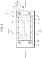
- the other end portion of the air flow passage 26 is closed, and thus the cooling air having flown in the air flow passage 26 flows from slits 27 provided in the left side surface of the cover 23 into an inside of the cover 23 as shown in FIG. 3 .
- the cooling air cools each of the cylindrical batteries 21 housed inside the cover 23.
- the cooling air of which temperature becomes higher after cooling the cylindrical batteries 21 is exhausted from the slit 27 provided in a right side surface of the cover 23 to an outside of the battery module 20.
- the air to be exhausted flows through a space between the battery module 20 and the casing 11.
- the air to be exhausted flows through a gap between the inlet nozzle 18 of the casing 11 as well as the through-portion 102 of the floor panel 101 and the cooling air duct 81, and is returned into the vehicle interior 104.
- the thermal diffusing plate 22 is a metallic plate provided with a number of through-holes 22a into which the cylindrical batteries 21 are inserted.
- the thermal diffusing plate 22 is made of metal such as aluminum, for example.
- the cylindrical batteries 21 are inserted into the through-holes 22a of the thermal diffusing plate 22.
- the cylindrical batteries 21 are then fixed to the through-holes 22a by filling a gap between inner surfaces (cylindrical surfaces) of the through-holes 22a and outer surfaces (cylindrical surfaces) of the cylindrical batteries 21 with an adhesive agent.
- the cylindrical batteries 21 are assembled into the through-holes 22a of the thermal diffusing plate 22, thereby transferring heat from the outer surfaces (cylindrical surfaces) of the cylindrical batteries 21 having a higher temperature to the thermal diffusing plate 22 by thermal conductivity so as to decrease the temperature of the cylindrical batteries 21 having a higher temperature. Furthermore, heat of the thermal diffusing plate 22 is transferred to the cylindrical batteries 21 having a lower temperature by thermal conductivity so as to increase the temperature of the cylindrical batteries 21 having a lower temperature.
- the respective cylindrical batteries 21 are held by the corresponding through-holes 22a so that heat transfer can be achieved between the cylindrical surfaces of the cylindrical batteries 21 and the thermal diffusing plate 22, thereby suppressing variation in temperature among the cylindrical batteries 21.
- the thermal diffusing plate 22 is formed by a metallic material having a high thermal conductivity, such as aluminum, so as to promote an efficient heat transfer among the cylindrical batteries 21.
- the thermal diffusing plate 22 has a thickness sufficient for holding the cylindrical batteries 21 by the cylindrical surfaces of the through-holes 22a, and achieving an effective heat transfer by thermal conductivity, specifically, approximately 10 to 20 mm, or an approximately 1/4 thickness of a length of each cylindrical battery 21, for example.
- the resin cover 23 is disposed above the thermal diffusing plate 22.
- the cover 23 includes a ceiling plate 23a and a rectangular cylinder 23b. Holes 23c are formed in the ceiling plate 23a so that respective positive electrodes 21a of the cylindrical batteries 21 project from these holes 23c.
- the rectangular cylinder 23b covers the outer circumference of the plural cylindrical batteries 21 that are assembled to the thermal diffusing plate 22.
- plural positive-electrode bus bars 29 are disposed onto the holes 23c of the cover 23 in such a manner that each of the positive-electrode bus bars 29 connects the positive electrodes 21 a of the cylindrical batteries 21 for each of several groups.
- the resin ceiling cover 31 is disposed onto the positive-electrode bus bars 29.
- an upper flange 24 and a lower flange 25 are formed on a side surface of the cover 23 in a manner as to protrude outward.
- Each of the upper flange 24 and the lower flange 25 is formed in an L-shape.
- the upper flange 24 includes a flange surface extending upward.
- the lower flange 25 includes a flange surface extending downward.
- a cover plate 28 is disposed to the respective flange surfaces of the upper flange 24 and the lower flange 25.
- the rectangular air flow passage 26 is formed by the upper and lower flanges 24, 25 and the cover plate 28. As shown in FIG. 2 and FIG.
- FIG. 5 a longitudinal side surface of the cover 23 that forms the air flow passage 26 is provided with the slits 27 that introduce the cooling air for the cylindrical batteries 21.
- FIG. 2 and FIG. 5 illustrate the slits 27 formed in the left side surface of the cover 23.
- the same slits 27 as those in the left side surface are also formed in the right side surface of the cover 23, as shown in FIG. 3 .
- the slits 27 formed in the right side surface of the cover 23 are used for exhausting the air after cooling the cylindrical batteries 21 from the inside of the cover 23.
- an upper surface 22b of the thermal diffusing plate 22, the cover 23, and the ceiling cover 31 house the cylindrical batteries 21 thereinside.
- the thermal diffusing plate 22, the cylindrical batteries 21, the cover 23, and the ceiling cover 31 constitute a first chamber 40 that is a space into which the cooling air to cool the cylindrical batteries 21 is introduced.
- the upper surface 22b of the thermal diffusing plate 22 is part of walls partitioning the first chamber 40.
- a negative-electrode bus bar assembly 30 that connects the negative electrodes 21b of the cylindrical batteries 21 for each of several groups is disposed on a bottom side of the lower surface 22c of the thermal diffusing plate 22.
- the negative-electrode bus bar assembly 30 is configured by arranging and resin-molding plural negative-electrode bus bars 30a.
- Each negative-electrode bus bar 30a is configured by forming respective holes 30c corresponding to the arrangement of the cylindrical batteries 21 in a plate having the same shape as that of the positive-electrode bus bar 29.
- a platy terminal 30b to be in contact with the negative electrode 21b of each cylindrical battery 21 is disposed to each hole 30c of each negative-electrode bus bar 30a.
- Each positive-electrode bus bar 29 connects the positive electrodes 21a of the cylindrical batteries 21 in each same group.
- Each negative-electrode bus bar 30a connects the negative electrodes 21b of the cylindrical batteries 21 in each same group.
- the cylindrical batteries 21 in a group connected by the respective positive-electrode bus bars 29 and negative-electrode bus bars 30a are connected to one another in parallel.
- the respective groups of the plural cylindrical batteries 21 connected in parallel are then connected in series.
- the series connection of the respective groups is carried out by connecting the respective positive-electrode bus bars 29 and the respective negative-electrode bus bars 30a by a connecting bus bar (not shown).
- the battery set is configured in this manner.
- the bottom cover 32 is disposed to a bottom side of the negative-electrode bus bar assembly 30.
- a central portion of the bottom cover 32 is recessed in a tray-shape, and a bottom surface thereof includes a reinforcing recessed-protruding portion 32a.
- a resin rib 30d protrudes from an outer circumference of the bottom surface of the negative-electrode bus bar assembly 30.
- the bottom cover 32 is disposed such that an outer circumference of the bottom cover 32 comes into contact with a front end of the rib 30d.
- the bottom cover 32 is formed by metal having a high heat transfer property, such as aluminum.
- the thermal diffusing plate 22, the cylindrical batteries 21, the negative-electrode bus bar assembly 30, and the bottom cover 32 are configured in this manner.
- the lower surface 22c of the thermal diffusing plate 22, the negative electrodes 21b of the cylindrical batteries 21, the rib 30d of the negative-electrode bus bar assembly 30, and the bottom cover 32 form a second chamber 50 that is a single room including an air space inside of the second chamber 50.
- the lower surface 22c of the thermal diffusing plate 22 is part of walls that partition the second chamber 50.
- an opening 30e in a substantially rectangular shape is provided at each longitudinal end of the negative-electrode bus bar assembly 30.
- An opening 22e is provided at each longitudinal end of the lower surface 22c of the thermal diffusing plate 22.
- An opening 22d is also provided in each longitudinal end surface of the thermal diffusing plate 22. The opening 22d in each longitudinal end surface and each corresponding opening 22e of the lower surface 22c of the thermal diffusing plate 22 are configured to communicate with each other through a flow passage bent in an L-shape.
- each opening 30e of the negative-electrode bus bar assembly 30 is overlaid with each corresponding opening 22e of the lower surface 22c of the thermal diffusing plate 22. Accordingly, the negative-electrode bus bar assembly 30 and the bottom cover 32 are attached to the thermal diffusing plate 22, thereby forming a flow passage that allows the second chamber 50 to communicate with the opening 22d in each end surface of the thermal diffusing plate 22.
- the negative electrode 21b of each cylindrical battery 21 has a structure to open an end surface thereof by inner pressure. Through this configuration, if gas is generated inside the cylindrical battery 21, it is possible to release the gas to the outside.
- the gas released from the negative electrode 21b of the cylindrical battery 21 flows into the second chamber 50 formed below the thermal diffusing plate 22.
- the gas having flown into the second chamber 50 flows through the second chamber 50 to the both longitudinal ends of the battery module 20.
- the gas flows through the opening 30e of the negative-electrode bus bar assembly 30, the opening 22e and the opening 22d of the thermal diffusing plate 22, and is then exhausted to the outside.
- the second chamber 50 serves as part of a smoke exhaust passage to exhaust the gas if the gas is released from the cylindrical batteries 21.
- the bottom cover 32 includes the recessed-protruding portion 32a that is inwardly recessed at the central portion in the width direction of the bottom cover 32.
- the bar heater 33 to heat the battery module 20 is disposed to an outer surface of this recessed-protruding portion 32a. Heat emitted from the bar heater 33 heats the bottom cover 32 from an outer surface of the bottom cover 32. Because the bottom cover 32 is made of a material excellent in heat transfer property, such as metal or the like, the temperature of the entire bottom cover 32 becomes increased by the heat of the bar heater 33.
- the bottom cover 32 of which temperature is increased heats the air in the second chamber 50 between the bottom cover 32 and the lower surface 22c of the thermal diffusing plate 22 from vertically below.
- the air inside the second chamber 50 is heated while moving as indicated by arrows 91 of FIG. 4 by convection.
- the heated air comes into contact with the lower surface 22c of the thermal diffusing plate 22 and also with the surfaces of the respective negative electrodes 21b of the cylindrical batteries 21 so as to heat these surfaces.
- the heated air heats the lower surface 22c of the thermal diffusing plate 22 and the respective surfaces of the negative electrodes 21b of the cylindrical batteries 21.
- the temperature of the air in contact with the negative electrodes 21b of the respective cylindrical batteries 21 is substantially uniform, and thus heat input from the air into the respective cylindrical batteries 21 becomes substantially uniform. Accordingly, variation in temperature among the respective heated cylindrical batteries 21 is unlikely to be caused.
- the thermal diffusing plate 22 is made of metal having a high thermal conductivity, such as aluminum; therefore, the heat inputted into the lower surface 22c of the thermal diffusing plate 22 transfers from the surface of each through-hole 22a of the thermal diffusing plate 22 to the cylindrical surface of each cylindrical battery 21.
- Each cylindrical battery 21 is started to be heated from the cylindrical surface thereof.
- the thermal diffusing plate 22 can efficiently promote the heat transfer among the cylindrical batteries 21, thus suppressing variation in temperature among the heated cylindrical batteries 21.
- the bar heater 33 disposed to the center of the bottom cover 32 circulates the air between the bottom cover 32 and the thermal diffusing plate 22 by convection, thereby heating the bottom cover 32 and the negative electrodes 21b of the cylindrical batteries 21.
- the battery pack of the first embodiment it is possible to suppress variation in temperature among the heated cylindrical batteries 21 by using the small bar heater 33. Through this configuration, it is possible to configure the battery pack 10 to be compact.
- the battery pack 10 of the first embodiment includes the second chamber 50 serving as the smoke exhaust passage to exhaust the gas if the gas is released from the cylindrical batteries 21.
- the bar heater 33 is configured to heat each cylindrical battery 21 through the air space in the second chamber 50. Hence, it is unnecessary to provide a dedicated air space between the bar heater 33 and the cylindrical batteries 21, or between the bar heater 33 and the thermal diffusing plate 22. Through this configuration, it is possible to configure the battery pack 10 to be compact.
- a tabular sheet heater 34 is used instead of using the bar heater 33 of the first embodiment.
- the sheet heater 34 is disposed to an outer surface on a bottom side of the bottom cover 32.
- the sheet heater 34 can heat a wide range of the surface on the bottom side of the bottom cover 32.
- an annular skirt 35 in a rectangular shape is provided in a manner as to form a third chamber 60 that is a substantially closed space in a room between the bottom cover 32 and the bottom plate 11 a of the casing 11 of the first embodiment.
- a left upper end of the skirt 35 is connected to the lower flange 25 of the cover 23.
- a right upper end of the skirt 35 is connected to the rib 30d of the right side surface of the cover 23.
- Each lower end of the skirt 35 is connected to the bottom plate 11a of the casing 11.
- a plate of the skirt 35 that connects the cover 23 or the thermal diffusing plate 22 to the bottom plate 11a of the casing 11 is also disposed to each longitudinal end of the battery module 20.
- the respective plates of the skirt 35 are so connected to one another as to form a rectangular annular shape. More specifically, the left and right lower plates of the battery module 20, and the lower plates at the both longitudinal ends of the battery module 20 are connected into a rectangular annular shape.
- the third chamber 60 surrounded by the skirt 35, the bottom cover 32, and the bottom plate 11 a of the casing 11 is formed into a substantially closed space. Hence, it is possible to suppress release of the heat of the bar heater 33 from the bottom of the bottom cover 32 to the other portions of the casing 11. It is also possible to suppress variation in temperature of the heated bottom cover 32 by circulating the air in the third chamber 60 by convection with the heat of the bar heater 33. Accordingly, the battery pack 10 of the present embodiment can save energy for heating the respective cylindrical batteries 21. In the third embodiment, it is possible to reduce variation in temperature among the heated cylindrical batteries 21 of the battery module 20 to be smaller than variation in temperature among the respective heated cylindrical batteries 21 of the first and the second embodiments.
- the sheet heater 34 of the second embodiment is disposed in the second chamber 50 between the thermal diffusing plate 22 and the bottom cover 32. As shown in FIG. 8 , the sheet heater 34 is disposed in the second chamber 50. The sheet heater 34 is disposed with a predetermined distance from the lower surface 22c of the thermal diffusing plate 22 and the negative electrodes 21b of the cylindrical batteries 21. The sheet heater 34 circulates the air in the second chamber 50 by convection as indicated by the arrows 91.
- the sheet heater 34 has a dimension sufficient for covering a range of the negative electrodes 21b of the cylindrical batteries 21.
- each embodiment promotes an effect to suppress variation in temperature among the heated cylindrical batteries 21 in the battery pack 10.
- the battery pack 10 is installed under the floor panel 101 of the electric-motor vehicle 100, but the present invention is not limited to the battery pack 10 installed in this manner.
- the invention may also be applicable to the battery pack 10 installed in a space behind a rear seat 106 as shown in FIG. 1 , or to the battery pack 10 installed in a luggage space.
- the disclosure may also be applicable to other electric-motor vehicles driven by engines and motors, such as hybrid vehicles.
Abstract
Description
- The invention relates to a structure of a battery pack including a battery module containing a plurality of cylindrical batteries.
- Battery packs configured by housing battery sets including a number of batteries connected in series or in parallel in casings are used in electric-motor vehicles or the like. Such battery packs cause problems, such as decrease in output thereof and decrease in recharging capacity, if the temperature thereof becomes lower. To cope with this, there has been a proposal to provide a battery pack with a heater so as to heat each battery by this heater if the temperature thereof is low.
- For example, Japanese Patent
JP 5392407 B2 - Japanese Patent Application Publication
JP 2012-243535 A - Japanese Patent Application Publication
JP 2008-053149 A - In a battery set including plural batteries connected in series or in parallel, difference in temperature among the batteries might cause non uniform charge-discharge behavior among the batteries; therefore, particular batteries experience significant decrease in residual capacity, which might cause progress of deterioration to the particular batteries. Hence, it is important in a battery set configured by plural batteries to maintain a uniform temperature among the batteries.
- Unfortunately, as in the case of the technique described in
JP 5392407 B2 JP 2012-243535 A JP 2008-053149 A JP 5392407 B2 JP 2012-243535 A JP 2008-053149 A - A configuration of suppressing variation in temperature among heated batteries in a battery pack is provided.
- According to an embodiment of the invention, a battery pack is provided. The battery pack includes a battery module and a heater. The battery module includes a plurality of, preferably cylindrical, batteries, a thermal diffusing plate, a first chamber, and a second chamber. The thermal diffusing plate houses and holds the plurality of batteries. The thermal diffusing plate may be made of metal having a high heat transfer property, in particular aluminium. The cooling air to cool each of the plurality of batteries may be introduced into the first chamber. The second chamber includes walls, and the walls includes a first part and a second part. At least the first part of the walls includes the thermal diffusing plate. The heater is disposed with a predetermined distance from the thermal diffusing plate. The heater may be a sheet heater. The heater is configured such that convection occurs in the second chamber. In other words, the heater heats the thermal diffusing plate by convection that occurs in the second chamber due to heat emitted from the heater.
- According to an embodiment of the invention, the second chamber may include an air space. The heater may be disposed on an opposite side of the air space from the thermal diffusing plate, and be configured such that the air convection occurs in the air space due to heat emitted from the heater.
- Through this configuration, in the embodiment, the heater heats the air in the vicinity of the thermal diffusing plate, and the thermal diffusing plate and the plural cylindrical batteries held by the thermal diffusing plate are heated by the convection of the heated air. Therefore, it is possible to prevent the thermal diffusing plate and the cylindrical batteries from being locally heated. Further, it is possible to suppress variation in temperature among the heated cylindrical batteries in the battery pack.
- According to an embodiment of the invention, the second part of the walls of the second chamber may include a bottom cover. The bottom cover may have a high heat transfer property, and the bottom cover may be assembled with a predetermined distance from the thermal diffusing plate. The heater may be disposed to or arranged at or assembled to the bottom cover.
- In this configuration, the bottom cover having a high heat transfer property is heated by the heater, thereby suppressing variation in temperature of the heated air space of the second chamber partitioned by the bottom cover and the thermal diffusing plate, and also suppressing variation in temperature among the heated cylindrical batteries in the battery pack.
- According to an embodiment of the invention, the heater may be arranged at the bottom cover such that it is disposed inside of the second chamber.
- According to an embodiment of the invention, the heater may be arranged at the bottom cover such that the heater is disposed outside of the second chamber.
- According to an embodiment of the invention, the battery pack may further comprise a casing for housing the battery module, an annular skirt connecting the battery module to a bottom plate of the casing, and a third chamber formed by the annular skirt, the bottom cover and the bottom plate, in which air is circulated by convection with the heat of the heater.
- According to an embodiment of the invention, the heater may be arranged at the center of the bottom cover so as to circulate the air between the bottom cover and the thermal diffusing plate by convection.
- According to an embodiment of the invention, the bottom cover may be made of metal, in particular aluminium.
- According to an embodiment of the invention, the second chamber may be a smoke exhaust passage to discharge gas released from the cylindrical batteries.
- Through this configuration, it is possible to effectively use the inner space of the battery pack, thus configuring the battery pack to be compact.
- According to an embodiment of the invention, the battery module may be configured such that when the battery pack is mounted to a vehicle the second chamber is located vertically below the first chamber. The heater may be located vertically below the thermal diffusing plate.
- This configuration heats the air space of the second chamber from vertically below, and thus the heated air is collected in the vicinity of the thermal diffusing plate located above the second chamber, thereby suppressing variation in temperature among the heated cylindrical batteries in the battery pack.
- According to an embodiment of the invention, the battery module may comprise two second chambers, and the heater may be located between the two chambers.
- The invention promotes an effect to suppress variation in temperature among the heated batteries in the battery pack.
- Features, advantages, and technical and industrial significance of exemplary embodiments of the invention will be described below with reference to the accompanying drawings, in which like numerals denote like elements, and wherein:
-
FIG. 1 is an explanatory view showing a state in which a battery pack according to a first embodiment of the invention is installed in an electric-motor vehicle; -
FIG. 2 is an elevation view of the battery pack; -
FIG. 3 is a plan view of the battery pack; -
FIG. 4 is a cross sectional view of the battery pack; -
FIG. 5 is an exploded perspective view of a battery module housed in the battery pack; -
FIG. 6 is a cross sectional view of a battery pack according to a second embodiment of the invention using a tabular heater; -
FIG. 7 is a cross sectional view of a battery pack according to a third embodiment of the invention providing a skirt so as to form a space between a lower portion of a battery module and a casing; and -
FIG. 8 is a cross sectional view of a battery pack according to a fourth embodiment of the invention providing a heater inward from a bottom cover. - Hereinafter, the first embodiment of the invention will be described with reference to drawings. In the following first embodiment, a
battery pack 10 of an electric-motor vehicle 100 driven by a motor generator MG will be explained. Thebattery pack 10 is disposed to a bottom surface of afloor panel 101 in the vicinity of afront seat 105, as shown inFIG. 1 . More specifically, as shown inFIG. 2 , acasing 11 is fixed to a bottom surface of thefloor panel 101 of the electric-motor vehicle 100 withbrackets 12 attached toside plates 11b,bolts 13a, and nuts 13b. This means that thecasing 11 is hung from thefloor panel 101. Cooling air to cool batteries housed in thebattery pack 10 is supplied by a coolingfan 103 disposed inside avehicle interior 104. InFIG. 1 , "TOP" denotes a vertically upward direction. Similarly, inFIG. 1 , "BOTTOM" denotes a vertically downward direction, "FRONT" denotes a frontward direction of the electric-motor vehicle 100, and "REAR" denotes a rearward direction of the electric-motor vehicle 100. - As shown in
FIG. 2 , thebattery pack 10 of the first embodiment includes abattery module 20 and abar heater 33 in thecasing 11. Thebattery module 20 includes pluralcylindrical batteries 21, a thermal diffusingplate 22, acover 23, aceiling cover 31, and abottom cover 32. Thethermal diffusing plate 22 holds thecylindrical batteries 21. Thecover 23 is made of resin, and covers an outer circumference of a set of the cylindrical batteries held by the thermal diffusingplate 22. Theceiling cover 31 is disposed onto an upper portion of thecover 23, and thebottom cover 32 is disposed below the thermal diffusingplate 22. Thebottom cover 32 is formed in a tray shape. Thecylindrical batteries 21 are chargeable and dischargeable secondary batteries, such as nickel-metal hydride batteries and lithium-ion batteries housed in cylindrical cases, for example. - An L-shaped
insulator 14 formed of resin is disposed at each lower cormer of each longitudinal end of the thermal diffusingplate 22. One surface of each L-shapedbracket 15 is fixed to an end surface of eachinsulator 14 with abolt 16a and anut 16b. The other surface of eachbracket 15 is fixed to an inner surface of abottom plate 11 a of thecasing 11 with abolt 17a and anut 17b. In this manner, the thermal diffusingplate 22 holding thecylindrical batteries 21 is fixed to the inner surface of thebottom plate 11 a of thecasing 11. - As shown in
FIG. 2 , anair flow passage 26 is formed in thebattery module 20. A coolingair duct 81 is connected to an open end of theair flow passage 26 via a connectingduct 82. The coolingair duct 81 is configured to introduce cooling air sent from the coolingfan 103 as shown inFIG. 1 into theair flow passage 26. As shown inFIG. 2 , the coolingair duct 81 is introduced from a through-portion 102 formed in thefloor panel 101 through aninlet nozzle 18 disposed to an upper part of thecasing 11 into thecasing 11. - As shown in
FIG. 2 andFIG. 3 , the cooling air sent from the coolingfan 103 flows through the coolingair duct 81 and the connectingduct 82 into theair flow passage 26. Theair flow passage 26 is formed to a left side surface of thebattery module 20. The other end portion of theair flow passage 26 is closed, and thus the cooling air having flown in theair flow passage 26 flows fromslits 27 provided in the left side surface of thecover 23 into an inside of thecover 23 as shown inFIG. 3 . The cooling air cools each of thecylindrical batteries 21 housed inside thecover 23. The cooling air of which temperature becomes higher after cooling thecylindrical batteries 21 is exhausted from theslit 27 provided in a right side surface of thecover 23 to an outside of thebattery module 20. As shown inFIG. 2 , the air to be exhausted flows through a space between thebattery module 20 and thecasing 11. The air to be exhausted flows through a gap between theinlet nozzle 18 of thecasing 11 as well as the through-portion 102 of thefloor panel 101 and the coolingair duct 81, and is returned into thevehicle interior 104. - Hereinafter, with reference to
FIG. 4 andFIG. 5 , the configuration of thebattery module 20 housed in thecasing 11 will be described. As shown inFIG. 5 , the thermal diffusingplate 22 is a metallic plate provided with a number of through-holes 22a into which thecylindrical batteries 21 are inserted. Thethermal diffusing plate 22 is made of metal such as aluminum, for example. Thecylindrical batteries 21 are inserted into the through-holes 22a of the thermal diffusingplate 22. Thecylindrical batteries 21 are then fixed to the through-holes 22a by filling a gap between inner surfaces (cylindrical surfaces) of the through-holes 22a and outer surfaces (cylindrical surfaces) of thecylindrical batteries 21 with an adhesive agent. Thecylindrical batteries 21 are assembled into the through-holes 22a of the thermal diffusingplate 22, thereby transferring heat from the outer surfaces (cylindrical surfaces) of thecylindrical batteries 21 having a higher temperature to the thermal diffusingplate 22 by thermal conductivity so as to decrease the temperature of thecylindrical batteries 21 having a higher temperature. Furthermore, heat of the thermal diffusingplate 22 is transferred to thecylindrical batteries 21 having a lower temperature by thermal conductivity so as to increase the temperature of thecylindrical batteries 21 having a lower temperature. The respectivecylindrical batteries 21 are held by the corresponding through-holes 22a so that heat transfer can be achieved between the cylindrical surfaces of thecylindrical batteries 21 and the thermal diffusingplate 22, thereby suppressing variation in temperature among thecylindrical batteries 21. Thethermal diffusing plate 22 is formed by a metallic material having a high thermal conductivity, such as aluminum, so as to promote an efficient heat transfer among thecylindrical batteries 21. Thethermal diffusing plate 22 has a thickness sufficient for holding thecylindrical batteries 21 by the cylindrical surfaces of the through-holes 22a, and achieving an effective heat transfer by thermal conductivity, specifically, approximately 10 to 20 mm, or an approximately 1/4 thickness of a length of eachcylindrical battery 21, for example. - As shown in
FIG. 4 , theresin cover 23 is disposed above the thermal diffusingplate 22. Thecover 23 includes aceiling plate 23a and arectangular cylinder 23b.Holes 23c are formed in theceiling plate 23a so that respectivepositive electrodes 21a of thecylindrical batteries 21 project from theseholes 23c. Therectangular cylinder 23b covers the outer circumference of the pluralcylindrical batteries 21 that are assembled to the thermal diffusingplate 22. As shown inFIG. 4 andFIG. 5 , plural positive-electrode bus bars 29 are disposed onto theholes 23c of thecover 23 in such a manner that each of the positive-electrode bus bars 29 connects thepositive electrodes 21 a of thecylindrical batteries 21 for each of several groups. Theresin ceiling cover 31 is disposed onto the positive-electrode bus bars 29. - As shown in
FIG. 4 andFIG. 5 , anupper flange 24 and alower flange 25 are formed on a side surface of thecover 23 in a manner as to protrude outward. Each of theupper flange 24 and thelower flange 25 is formed in an L-shape. Theupper flange 24 includes a flange surface extending upward. Thelower flange 25 includes a flange surface extending downward. As shown inFIG. 4 , acover plate 28 is disposed to the respective flange surfaces of theupper flange 24 and thelower flange 25. The rectangularair flow passage 26 is formed by the upper andlower flanges cover plate 28. As shown inFIG. 2 andFIG. 5 , a longitudinal side surface of thecover 23 that forms theair flow passage 26 is provided with theslits 27 that introduce the cooling air for thecylindrical batteries 21.FIG. 2 andFIG. 5 illustrate theslits 27 formed in the left side surface of thecover 23. However, thesame slits 27 as those in the left side surface are also formed in the right side surface of thecover 23, as shown inFIG. 3 . As aforementioned, theslits 27 formed in the right side surface of thecover 23 are used for exhausting the air after cooling thecylindrical batteries 21 from the inside of thecover 23. - With the above configuration, an
upper surface 22b of the thermal diffusingplate 22, thecover 23, and theceiling cover 31 house thecylindrical batteries 21 thereinside. Thethermal diffusing plate 22, thecylindrical batteries 21, thecover 23, and theceiling cover 31 constitute afirst chamber 40 that is a space into which the cooling air to cool thecylindrical batteries 21 is introduced. Theupper surface 22b of the thermal diffusingplate 22 is part of walls partitioning thefirst chamber 40. - As shown in
FIG. 4 andFIG. 5 , a negative-electrodebus bar assembly 30 that connects thenegative electrodes 21b of thecylindrical batteries 21 for each of several groups is disposed on a bottom side of thelower surface 22c of the thermal diffusingplate 22. As shown inFIG. 5 , the negative-electrodebus bar assembly 30 is configured by arranging and resin-molding plural negative-electrode bus bars 30a. Each negative-electrode bus bar 30a is configured by formingrespective holes 30c corresponding to the arrangement of thecylindrical batteries 21 in a plate having the same shape as that of the positive-electrode bus bar 29. Aplaty terminal 30b to be in contact with thenegative electrode 21b of eachcylindrical battery 21 is disposed to eachhole 30c of each negative-electrode bus bar 30a. - Each positive-
electrode bus bar 29 connects thepositive electrodes 21a of thecylindrical batteries 21 in each same group. Each negative-electrode bus bar 30a connects thenegative electrodes 21b of thecylindrical batteries 21 in each same group. Thecylindrical batteries 21 in a group connected by the respective positive-electrode bus bars 29 and negative-electrode bus bars 30a are connected to one another in parallel. The respective groups of the pluralcylindrical batteries 21 connected in parallel are then connected in series. The series connection of the respective groups is carried out by connecting the respective positive-electrode bus bars 29 and the respective negative-electrode bus bars 30a by a connecting bus bar (not shown). The battery set is configured in this manner. - As shown in
FIG. 4 andFIG. 5 , thebottom cover 32 is disposed to a bottom side of the negative-electrodebus bar assembly 30. A central portion of thebottom cover 32 is recessed in a tray-shape, and a bottom surface thereof includes a reinforcing recessed-protrudingportion 32a. As shown inFIG. 4 , aresin rib 30d protrudes from an outer circumference of the bottom surface of the negative-electrodebus bar assembly 30. Thebottom cover 32 is disposed such that an outer circumference of thebottom cover 32 comes into contact with a front end of therib 30d. Thebottom cover 32 is formed by metal having a high heat transfer property, such as aluminum. - The
thermal diffusing plate 22, thecylindrical batteries 21, the negative-electrodebus bar assembly 30, and thebottom cover 32 are configured in this manner. Thelower surface 22c of the thermal diffusingplate 22, thenegative electrodes 21b of thecylindrical batteries 21, therib 30d of the negative-electrodebus bar assembly 30, and thebottom cover 32 form asecond chamber 50 that is a single room including an air space inside of thesecond chamber 50. Thelower surface 22c of the thermal diffusingplate 22 is part of walls that partition thesecond chamber 50. - As shown in
FIG. 5 , anopening 30e in a substantially rectangular shape is provided at each longitudinal end of the negative-electrodebus bar assembly 30. Anopening 22e is provided at each longitudinal end of thelower surface 22c of the thermal diffusingplate 22. Anopening 22d is also provided in each longitudinal end surface of the thermal diffusingplate 22. Theopening 22d in each longitudinal end surface and eachcorresponding opening 22e of thelower surface 22c of the thermal diffusingplate 22 are configured to communicate with each other through a flow passage bent in an L-shape. If the negative-electrodebus bar assembly 30 is attached to thelower surface 22c of the thermal diffusingplate 22, eachopening 30e of the negative-electrodebus bar assembly 30 is overlaid with eachcorresponding opening 22e of thelower surface 22c of the thermal diffusingplate 22. Accordingly, the negative-electrodebus bar assembly 30 and thebottom cover 32 are attached to the thermal diffusingplate 22, thereby forming a flow passage that allows thesecond chamber 50 to communicate with theopening 22d in each end surface of the thermal diffusingplate 22. - The
negative electrode 21b of eachcylindrical battery 21 has a structure to open an end surface thereof by inner pressure. Through this configuration, if gas is generated inside thecylindrical battery 21, it is possible to release the gas to the outside. The gas released from thenegative electrode 21b of thecylindrical battery 21 flows into thesecond chamber 50 formed below the thermal diffusingplate 22. The gas having flown into thesecond chamber 50 flows through thesecond chamber 50 to the both longitudinal ends of thebattery module 20. The gas flows through theopening 30e of the negative-electrodebus bar assembly 30, theopening 22e and theopening 22d of the thermal diffusingplate 22, and is then exhausted to the outside. In this manner, thesecond chamber 50 serves as part of a smoke exhaust passage to exhaust the gas if the gas is released from thecylindrical batteries 21. - As shown in
FIG. 4 , thebottom cover 32 includes the recessed-protrudingportion 32a that is inwardly recessed at the central portion in the width direction of thebottom cover 32. Thebar heater 33 to heat thebattery module 20 is disposed to an outer surface of this recessed-protrudingportion 32a. Heat emitted from thebar heater 33 heats the bottom cover 32 from an outer surface of thebottom cover 32. Because thebottom cover 32 is made of a material excellent in heat transfer property, such as metal or the like, the temperature of theentire bottom cover 32 becomes increased by the heat of thebar heater 33. Thebottom cover 32 of which temperature is increased heats the air in thesecond chamber 50 between thebottom cover 32 and thelower surface 22c of the thermal diffusingplate 22 from vertically below. Hence, the air inside thesecond chamber 50 is heated while moving as indicated byarrows 91 ofFIG. 4 by convection. The heated air comes into contact with thelower surface 22c of the thermal diffusingplate 22 and also with the surfaces of the respectivenegative electrodes 21b of thecylindrical batteries 21 so as to heat these surfaces. Specifically, the heated air heats thelower surface 22c of the thermal diffusingplate 22 and the respective surfaces of thenegative electrodes 21b of thecylindrical batteries 21. The temperature of the air in contact with thenegative electrodes 21b of the respectivecylindrical batteries 21 is substantially uniform, and thus heat input from the air into the respectivecylindrical batteries 21 becomes substantially uniform. Accordingly, variation in temperature among the respective heatedcylindrical batteries 21 is unlikely to be caused. As aforementioned, the thermal diffusingplate 22 is made of metal having a high thermal conductivity, such as aluminum; therefore, the heat inputted into thelower surface 22c of the thermal diffusingplate 22 transfers from the surface of each through-hole 22a of the thermal diffusingplate 22 to the cylindrical surface of eachcylindrical battery 21. Eachcylindrical battery 21 is started to be heated from the cylindrical surface thereof. Thethermal diffusing plate 22 can efficiently promote the heat transfer among thecylindrical batteries 21, thus suppressing variation in temperature among the heatedcylindrical batteries 21. - In this manner, in the
battery pack 10 of the first embodiment, thebar heater 33 disposed to the center of thebottom cover 32 circulates the air between thebottom cover 32 and the thermal diffusingplate 22 by convection, thereby heating thebottom cover 32 and thenegative electrodes 21b of thecylindrical batteries 21. Specifically, in the battery pack of the first embodiment, it is possible to suppress variation in temperature among the heatedcylindrical batteries 21 by using thesmall bar heater 33. Through this configuration, it is possible to configure thebattery pack 10 to be compact. - The
battery pack 10 of the first embodiment includes thesecond chamber 50 serving as the smoke exhaust passage to exhaust the gas if the gas is released from thecylindrical batteries 21. Thebar heater 33 is configured to heat eachcylindrical battery 21 through the air space in thesecond chamber 50. Hence, it is unnecessary to provide a dedicated air space between thebar heater 33 and thecylindrical batteries 21, or between thebar heater 33 and the thermal diffusingplate 22. Through this configuration, it is possible to configure thebattery pack 10 to be compact. - Next, with reference to
FIG. 6 , the second embodiment of the invention will be described. The same reference numerals are used for components that are the same as those of the aforementioned first embodiment, and description thereof will be omitted. In the second embodiment as shown inFIG. 6 , atabular sheet heater 34 is used instead of using thebar heater 33 of the first embodiment. - As shown in
FIG. 6 , in thebattery pack 10 of the second embodiment, thesheet heater 34 is disposed to an outer surface on a bottom side of thebottom cover 32. Thesheet heater 34 can heat a wide range of the surface on the bottom side of thebottom cover 32. Hence, it is possible to reduce variation in temperature of theheated bottom cover 32 in the second embodiment to be smaller than variation in temperature of theheated bottom cover 32 in the first embodiment. Accordingly, it is possible to reduce local variation in temperature in the air space between the thermal diffusingplate 22 and thebottom cover 32 in the second embodiment to be smaller than the variation in temperature in the air space between the thermal diffusingplate 22 and thebottom cover 32 in the first embodiment. Consequently, it is possible to reduce variation in temperature among the heatedcylindrical batteries 21 of thebattery module 20 in the second embodiment to be smaller than variation in temperature among the heatedcylindrical batteries 21 in the first embodiment. - Next, with reference to
FIG. 7 , the third embodiment of the invention will be explained. The same reference numerals are used for components that are the same as those of the aforementioned first embodiment, and description thereof will be omitted. In the third embodiment as shown inFIG. 7 , anannular skirt 35 in a rectangular shape is provided in a manner as to form athird chamber 60 that is a substantially closed space in a room between thebottom cover 32 and thebottom plate 11 a of thecasing 11 of the first embodiment. As shown inFIG. 7 , a left upper end of theskirt 35 is connected to thelower flange 25 of thecover 23. A right upper end of theskirt 35 is connected to therib 30d of the right side surface of thecover 23. Each lower end of theskirt 35 is connected to thebottom plate 11a of thecasing 11. A plate of theskirt 35 that connects thecover 23 or the thermal diffusingplate 22 to thebottom plate 11a of thecasing 11 is also disposed to each longitudinal end of thebattery module 20. The respective plates of theskirt 35 are so connected to one another as to form a rectangular annular shape. More specifically, the left and right lower plates of thebattery module 20, and the lower plates at the both longitudinal ends of thebattery module 20 are connected into a rectangular annular shape. - The
third chamber 60 surrounded by theskirt 35, thebottom cover 32, and thebottom plate 11 a of thecasing 11 is formed into a substantially closed space. Hence, it is possible to suppress release of the heat of thebar heater 33 from the bottom of thebottom cover 32 to the other portions of thecasing 11. It is also possible to suppress variation in temperature of theheated bottom cover 32 by circulating the air in thethird chamber 60 by convection with the heat of thebar heater 33. Accordingly, thebattery pack 10 of the present embodiment can save energy for heating the respectivecylindrical batteries 21. In the third embodiment, it is possible to reduce variation in temperature among the heatedcylindrical batteries 21 of thebattery module 20 to be smaller than variation in temperature among the respective heatedcylindrical batteries 21 of the first and the second embodiments. - Next, with reference to
FIG. 8 , the fourth embodiment of the invention will be explained. The same reference numerals are used for components that are the same as those of the aforementioned first embodiment, and description thereof will be omitted. In the fourth embodiment as shown inFIG. 8 , thesheet heater 34 of the second embodiment is disposed in thesecond chamber 50 between the thermal diffusingplate 22 and thebottom cover 32. As shown inFIG. 8 , thesheet heater 34 is disposed in thesecond chamber 50. Thesheet heater 34 is disposed with a predetermined distance from thelower surface 22c of the thermal diffusingplate 22 and thenegative electrodes 21b of thecylindrical batteries 21. Thesheet heater 34 circulates the air in thesecond chamber 50 by convection as indicated by thearrows 91. With this convection, the thermal diffusingplate 22 and thenegative electrodes 21b of thecylindrical batteries 21 are heated. In the fourth embodiment, thesheet heater 34 has a dimension sufficient for covering a range of thenegative electrodes 21b of thecylindrical batteries 21. Through this configuration, in the fourth embodiment, variation in temperature among the heatedcylindrical batteries 21 can be reduced to be smaller than variation in temperature among thecylindrical batteries 21 in each of the first embodiment, the second embodiment, and the third embodiment. - As aforementioned, each embodiment promotes an effect to suppress variation in temperature among the heated
cylindrical batteries 21 in thebattery pack 10. - In each of the aforementioned embodiments, it has been explained that the
battery pack 10 is installed under thefloor panel 101 of the electric-motor vehicle 100, but the present invention is not limited to thebattery pack 10 installed in this manner. The invention may also be applicable to thebattery pack 10 installed in a space behind arear seat 106 as shown inFIG. 1 , or to thebattery pack 10 installed in a luggage space. The disclosure may also be applicable to other electric-motor vehicles driven by engines and motors, such as hybrid vehicles. - The invention is not limited to the aforementioned embodiments, and includes all changes and modifications without departing from the technical scope and spirit of the invention specified by the claims.
Claims (11)
- A battery pack (10) comprising:a battery module (20) includinga plurality of, preferably cylindrical, batteries (21),a thermal diffusing plate (22), preferably made of metal having a high heat transfer property, in particular aluminium, housing and holding the plurality of batteries (21),a first chamber (40) into which cooling air to cool each of the plurality of batteries (21) can be introduced, anda second chamber (50) including walls, the walls including a first part and a second part, at least the first part of the walls including the thermal diffusing plate (22); characterized by comprising:a heater (33; 34), preferably a sheet heater, disposed with a predetermined distance from the thermal diffusing plate (22),so as to heat the thermal diffusing plate (22) by convection that occurs in the second chamber (50) due to heat emitted from the heater (33; 34).
- The battery pack (10) according to claim 1, wherein
the second chamber (50) includes an air space, and
the heater (33; 34) is disposed on an opposite side of the air space from the thermal diffusing plate (22) so that air convection occurs in the air space due to heat emitted from the heater (33; 34). - The battery pack (10) according to claim 1 or 2, wherein
the second part of the walls of the second chamber (50) includes a bottom cover (32),
the bottom cover (32) has a high heat transfer property,
the bottom cover (32) is assembled with a predetermined distance from the thermal diffusing plate (22), and
the heater (33; 34) is arranged at the bottom cover (32). - The battery pack (10) according to claim 3, wherein the heater (34) is arranged at the bottom cover (34) such that it is disposed inside of the second chamber (50).
- The battery pack (10) according to claim 3, wherein the heater (33; 34) is arranged at the bottom cover (32) such that the heater (33; 34) is disposed outside of the second chamber (50).
- The battery pack (10) according to claim 5, further comprising:a casing (11) for housing the battery module (20);an annular skirt (35) connecting the battery module (20) to a bottom plate (11a) of the casing (11); anda third chamber (60) formed by the annular skirt (35), the bottom cover (32) and the bottom plate (11), in which air is circulated by convection with the heat of the heater (33).
- The battery pack (10) according to any one of claims 3 to 6, wherein the heater (33) is arranged at the center of the bottom cover (32) so as to circulate the air between the bottom cover (32) and the thermal diffusing plate (22) by convection.
- The battery pack (10) according to any one of claims 3 to 7, wherein the bottom cover (32) is made of metal, in particular aluminium.
- The battery pack (10) according to any one of claims 1 to 8, wherein the second chamber (50) is a smoke exhaust passage to discharge gas released from the batteries (21).
- The battery pack (10) according to any one of claims 1 to 9, wherein
the battery module (20) is configured such that when the battery pack is mounted to a vehicle the second chamber (50) is located vertically below the first chamber (40), and the heater (33) is located vertically below the thermal diffusing plate (22). - The battery pack (10) according to any one of claims 1 to 10, wherein
the battery module (20) comprises two second chambers (50), and
the heater (33) is located between the two chambers (50).
Applications Claiming Priority (1)
| Application Number | Priority Date | Filing Date | Title |
|---|---|---|---|
| JP2015059201A JP6248972B2 (en) | 2015-03-23 | 2015-03-23 | Battery pack |
Publications (2)
| Publication Number | Publication Date |
|---|---|
| EP3073547A1 true EP3073547A1 (en) | 2016-09-28 |
| EP3073547B1 EP3073547B1 (en) | 2019-07-24 |
Family
ID=55587188
Family Applications (1)
| Application Number | Title | Priority Date | Filing Date |
|---|---|---|---|
| EP16161391.4A Active EP3073547B1 (en) | 2015-03-23 | 2016-03-21 | Battery pack |
Country Status (9)
| Country | Link |
|---|---|
| US (1) | US10340562B2 (en) |
| EP (1) | EP3073547B1 (en) |
| JP (1) | JP6248972B2 (en) |
| KR (1) | KR101967824B1 (en) |
| CN (1) | CN105990622B (en) |
| BR (1) | BR102016005845B1 (en) |
| CA (1) | CA2924471C (en) |
| MY (1) | MY177278A (en) |
| RU (1) | RU2636059C2 (en) |
Families Citing this family (25)
| Publication number | Priority date | Publication date | Assignee | Title |
|---|---|---|---|---|
| EP3131958B1 (en) | 2014-04-17 | 2023-03-22 | Imertech Sas | Polymer-based foam compositions comprising inorganic particulate fillers |
| JP6396960B2 (en) * | 2016-08-31 | 2018-09-26 | 株式会社Subaru | Battery pack |
| KR102205312B1 (en) * | 2016-09-13 | 2021-01-20 | 주식회사 엘지화학 | Battery pack |
| KR102082906B1 (en) * | 2016-10-10 | 2020-02-28 | 주식회사 엘지화학 | Battery module assembly |
| CN110100325B (en) * | 2016-12-27 | 2022-04-08 | 松下知识产权经营株式会社 | Battery module |
| KR101965373B1 (en) | 2017-01-06 | 2019-04-03 | 주식회사 엘지화학 | Cylindrical Battery Module |
| JP2018113219A (en) * | 2017-01-13 | 2018-07-19 | トヨタ自動車株式会社 | Power storage device |
| KR102397774B1 (en) | 2017-11-14 | 2022-05-13 | 주식회사 엘지에너지솔루션 | Battery module and battery pack having the same |
| KR102288405B1 (en) * | 2017-12-26 | 2021-08-09 | 주식회사 엘지에너지솔루션 | Cylindrical battery cell assembly improved in space utilization and safety and battery module including the same |
| FR3077430B1 (en) * | 2018-01-29 | 2020-02-14 | Commissariat A L'energie Atomique Et Aux Energies Alternatives | ELECTRIC BATTERY MODULE AND BATTERY COMPRISING SEVERAL MODULES |
| CN108281590B (en) * | 2018-03-29 | 2024-02-02 | 长沙优力电驱动系统有限公司 | Battery thermal management device and battery provided with same |
| JP2021522658A (en) * | 2018-04-27 | 2021-08-30 | ビーエイエスエフ・ソシエタス・エウロパエアBasf Se | Electrochemical energy reservoir |
| RU2692694C1 (en) * | 2018-07-25 | 2019-06-26 | Федеральное государственное казенное военное образовательное учреждение высшего образования "Рязанское высшее воздушно-десантное ордена Суворова дважды Краснознаменное командное училище имени генерала армии В.Ф. Маргелова" Министерства обороны Российской Федерации | Heated storage battery |
| CN110858677B (en) * | 2018-08-22 | 2023-04-11 | 太普动力新能源(常熟)股份有限公司 | Battery module with heater |
| RU192515U1 (en) * | 2018-10-10 | 2019-09-19 | Акционерное общество "ПКК МИЛАНДР" | BATTERY MODULE MODULE |
| FR3089354B1 (en) * | 2018-12-03 | 2021-08-20 | Blue Solutions | Device for fixing an electrical energy storage module |
| JP7110974B2 (en) * | 2018-12-26 | 2022-08-02 | 株式会社オートネットワーク技術研究所 | Power supply system and automobile |
| CN109830625B (en) * | 2019-01-22 | 2021-10-26 | 重庆交通大学 | Cylindrical battery thermal management system |
| WO2021070287A1 (en) | 2019-10-09 | 2021-04-15 | 日産自動車株式会社 | Cooling device for on-board battery |
| EP3958378B1 (en) | 2020-07-10 | 2023-12-13 | Contemporary Amperex Technology Co., Limited | Battery, electric device, and method and device for preparing battery |
| KR20220095224A (en) | 2020-07-10 | 2022-07-06 | 컨템포러리 엠퍼렉스 테크놀로지 씨오., 리미티드 | Batteries and related devices, manufacturing methods and manufacturing devices |
| KR20220072885A (en) * | 2020-11-23 | 2022-06-03 | 주식회사 엘지에너지솔루션 | Air-Cooling battery module with individual battery cell cooling structures |
| FR3123157B1 (en) * | 2021-05-21 | 2023-10-06 | Accumulateurs Fixes | Battery module |
| DE102021123314A1 (en) | 2021-09-09 | 2023-03-09 | Dr. Ing. H.C. F. Porsche Aktiengesellschaft | electric vehicle |
| CN114683805B (en) * | 2022-04-19 | 2023-06-02 | 三一电动车科技有限公司 | Thermal management system, work machine, control method, and controller |
Citations (10)
| Publication number | Priority date | Publication date | Assignee | Title |
|---|---|---|---|---|
| EP1333521A2 (en) * | 2002-01-30 | 2003-08-06 | Sanyo Electric Co., Ltd. | Battery apparatus with temperature sensors |
| US20060068278A1 (en) * | 2003-01-04 | 2006-03-30 | Bloom Richard L | Vehicle battery pack insulator |
| EP1705743A1 (en) * | 2005-03-25 | 2006-09-27 | Samsung SDI Co., Ltd. | Battery module |
| JP2008053149A (en) | 2006-08-28 | 2008-03-06 | Panasonic Ev Energy Co Ltd | Battery pack structure with heater |
| US20120003516A1 (en) * | 2010-06-30 | 2012-01-05 | Nissan Technical Center North America, Inc. | Vehicle battery temperature control system and method |
| WO2012124446A1 (en) * | 2011-03-14 | 2012-09-20 | 株式会社 豊田自動織機 | Battery module |
| JP2012243535A (en) | 2011-05-18 | 2012-12-10 | Sanyo Electric Co Ltd | Battery pack |
| US20130017422A1 (en) * | 2011-07-12 | 2013-01-17 | Bae Joon-Soo | Battery pack assembly |
| EP2667076A1 (en) * | 2011-10-31 | 2013-11-27 | Panasonic Corporation | Secondary battery unit |
| JP5392407B2 (en) | 2011-04-28 | 2014-01-22 | トヨタ自動車株式会社 | Battery pack |
Family Cites Families (20)
| Publication number | Priority date | Publication date | Assignee | Title |
|---|---|---|---|---|
| DE102005009356A1 (en) * | 2005-03-01 | 2006-09-07 | Ethicon Gmbh | Surgical implant |
| JP4902164B2 (en) | 2005-09-28 | 2012-03-21 | 三洋電機株式会社 | Power supply |
| US20070078353A1 (en) * | 2005-10-04 | 2007-04-05 | Welch Allyn, Inc. | Method and apparatus for removing baseline wander from an ECG signal |
| JP2008140630A (en) * | 2006-11-30 | 2008-06-19 | Sanyo Electric Co Ltd | Power source device for vehicle and electric vehicle with power source device |
| JP4948200B2 (en) * | 2007-02-19 | 2012-06-06 | プライムアースEvエナジー株式会社 | Battery structure with heater |
| KR100839374B1 (en) | 2007-04-27 | 2008-06-19 | 삼성에스디아이 주식회사 | Battery module |
| JP5136263B2 (en) | 2008-07-28 | 2013-02-06 | トヨタ自動車株式会社 | Power storage device |
| JP5409160B2 (en) * | 2009-07-24 | 2014-02-05 | 本田技研工業株式会社 | Temperature control method for vehicle and power storage device |
| JP2011071011A (en) * | 2009-09-28 | 2011-04-07 | Kawasaki Heavy Ind Ltd | Stacked battery module and battery system using the same |
| KR101093695B1 (en) * | 2009-10-16 | 2011-12-19 | 삼성에스디아이 주식회사 | Battery module |
| JPWO2011092773A1 (en) * | 2010-01-29 | 2013-05-30 | パナソニック株式会社 | Battery module |
| JP5464168B2 (en) * | 2010-06-04 | 2014-04-09 | 株式会社デンソー | Power supply |
| JP5900011B2 (en) * | 2011-03-11 | 2016-04-06 | 日産自動車株式会社 | Thin heater module |
| JP5201296B2 (en) * | 2011-04-26 | 2013-06-05 | トヨタ自動車株式会社 | Power supply |
| EP2760105A4 (en) | 2011-09-21 | 2015-01-28 | Toyota Motor Co Ltd | Vehicle battery control device and vehicle battery control method |
| WO2013076770A1 (en) * | 2011-11-24 | 2013-05-30 | トヨタ自動車株式会社 | Power storage device, vehicle |
| JP6043555B2 (en) * | 2012-09-12 | 2016-12-14 | 昭和電工株式会社 | Battery cooling structure |
| RU140037U1 (en) * | 2013-10-31 | 2014-04-27 | Общество с ограниченной ответственностью "Системы управления хранением энергии" (ООО "СУХЭ") | HEAT PROTECTED LITHIUM-ION BATTERY |
| JP6256397B2 (en) | 2015-03-23 | 2018-01-10 | トヨタ自動車株式会社 | Battery pack |
| JP6156421B2 (en) | 2015-03-23 | 2017-07-05 | トヨタ自動車株式会社 | Battery pack |
-
2015
- 2015-03-23 JP JP2015059201A patent/JP6248972B2/en active Active
-
2016
- 2016-03-16 KR KR1020160031381A patent/KR101967824B1/en active IP Right Grant
- 2016-03-17 BR BR102016005845-7A patent/BR102016005845B1/en active IP Right Grant
- 2016-03-18 CN CN201610157499.6A patent/CN105990622B/en active Active
- 2016-03-21 RU RU2016110139A patent/RU2636059C2/en active
- 2016-03-21 MY MYPI2016700994A patent/MY177278A/en unknown
- 2016-03-21 EP EP16161391.4A patent/EP3073547B1/en active Active
- 2016-03-22 US US15/077,314 patent/US10340562B2/en active Active
- 2016-03-22 CA CA2924471A patent/CA2924471C/en active Active
Patent Citations (11)
| Publication number | Priority date | Publication date | Assignee | Title |
|---|---|---|---|---|
| EP1333521A2 (en) * | 2002-01-30 | 2003-08-06 | Sanyo Electric Co., Ltd. | Battery apparatus with temperature sensors |
| US20060068278A1 (en) * | 2003-01-04 | 2006-03-30 | Bloom Richard L | Vehicle battery pack insulator |
| EP1705743A1 (en) * | 2005-03-25 | 2006-09-27 | Samsung SDI Co., Ltd. | Battery module |
| JP2008053149A (en) | 2006-08-28 | 2008-03-06 | Panasonic Ev Energy Co Ltd | Battery pack structure with heater |
| US20080096072A1 (en) * | 2006-08-28 | 2008-04-24 | Panasonic Ev Energy Co., Ltd. | Battery pack structure with heater |
| US20120003516A1 (en) * | 2010-06-30 | 2012-01-05 | Nissan Technical Center North America, Inc. | Vehicle battery temperature control system and method |
| WO2012124446A1 (en) * | 2011-03-14 | 2012-09-20 | 株式会社 豊田自動織機 | Battery module |
| JP5392407B2 (en) | 2011-04-28 | 2014-01-22 | トヨタ自動車株式会社 | Battery pack |
| JP2012243535A (en) | 2011-05-18 | 2012-12-10 | Sanyo Electric Co Ltd | Battery pack |
| US20130017422A1 (en) * | 2011-07-12 | 2013-01-17 | Bae Joon-Soo | Battery pack assembly |
| EP2667076A1 (en) * | 2011-10-31 | 2013-11-27 | Panasonic Corporation | Secondary battery unit |
Also Published As
| Publication number | Publication date |
|---|---|
| CA2924471C (en) | 2018-02-20 |
| CN105990622B (en) | 2018-09-28 |
| KR20160113972A (en) | 2016-10-04 |
| CA2924471A1 (en) | 2016-09-23 |
| US20160285140A1 (en) | 2016-09-29 |
| JP6248972B2 (en) | 2017-12-20 |
| MY177278A (en) | 2020-09-10 |
| KR101967824B1 (en) | 2019-04-10 |
| CN105990622A (en) | 2016-10-05 |
| RU2636059C2 (en) | 2017-11-20 |
| JP2016178063A (en) | 2016-10-06 |
| RU2016110139A (en) | 2017-09-28 |
| US10340562B2 (en) | 2019-07-02 |
| BR102016005845A2 (en) | 2016-09-27 |
| EP3073547B1 (en) | 2019-07-24 |
| BR102016005845B1 (en) | 2022-09-27 |
Similar Documents
| Publication | Publication Date | Title |
|---|---|---|
| CA2924471C (en) | Battery pack | |
| EP3073546B1 (en) | Battery pack | |
| JP6823673B2 (en) | Cooling system and battery module assembly for cooling the battery cell | |
| JP6011949B2 (en) | Automotive battery | |
| US9614197B2 (en) | Onboard battery | |
| US20220314772A1 (en) | Underbody for vehicle | |
| US10326184B2 (en) | Battery pack | |
| JP2008251378A (en) | Cooling structure for battery pack | |
| JP2009289636A (en) | Temperature adjusting structure of power supply apparatus | |
| JP2005183217A (en) | Vehicular power supply apparatus | |
| EP4087021A1 (en) | Air-cooled battery pack for electric vehicle | |
| JP5822281B2 (en) | Battery pack for electric vehicles | |
| JP2022103534A (en) | Cooling structure for battery pack | |
| JP6285197B2 (en) | Automotive battery | |
| JP6344250B2 (en) | Electric vehicle | |
| JP2007294290A (en) | Power storage pack | |
| JP6879815B2 (en) | In-vehicle battery | |
| JP6119529B2 (en) | Battery system | |
| JP6743576B2 (en) | Battery pack structure | |
| JP2013119338A (en) | Vehicle | |
| KR20130110716A (en) | An inner-case of cell wherein the cell is able to slide in it |
Legal Events
| Date | Code | Title | Description |
|---|---|---|---|
| PUAI | Public reference made under article 153(3) epc to a published international application that has entered the european phase |
Free format text: ORIGINAL CODE: 0009012 |
|
| 17P | Request for examination filed |
Effective date: 20160321 |
|
| AK | Designated contracting states |
Kind code of ref document: A1 Designated state(s): AL AT BE BG CH CY CZ DE DK EE ES FI FR GB GR HR HU IE IS IT LI LT LU LV MC MK MT NL NO PL PT RO RS SE SI SK SM TR |
|
| AX | Request for extension of the european patent |
Extension state: BA ME |
|
| STAA | Information on the status of an ep patent application or granted ep patent |
Free format text: STATUS: EXAMINATION IS IN PROGRESS |
|
| 17Q | First examination report despatched |
Effective date: 20170919 |
|
| GRAP | Despatch of communication of intention to grant a patent |
Free format text: ORIGINAL CODE: EPIDOSNIGR1 |
|
| STAA | Information on the status of an ep patent application or granted ep patent |
Free format text: STATUS: GRANT OF PATENT IS INTENDED |
|
| RIC1 | Information provided on ipc code assigned before grant |
Ipc: H01M 10/6561 20140101ALI20190201BHEP Ipc: H01M 10/6555 20140101ALI20190201BHEP Ipc: H01M 10/657 20140101ALI20190201BHEP Ipc: H01M 10/613 20140101ALI20190201BHEP Ipc: H01M 10/615 20140101ALI20190201BHEP Ipc: H01M 10/625 20140101ALI20190201BHEP Ipc: H01M 2/10 20060101AFI20190201BHEP |
|
| INTG | Intention to grant announced |
Effective date: 20190228 |
|
| GRAS | Grant fee paid |
Free format text: ORIGINAL CODE: EPIDOSNIGR3 |
|
| GRAA | (expected) grant |
Free format text: ORIGINAL CODE: 0009210 |
|
| STAA | Information on the status of an ep patent application or granted ep patent |
Free format text: STATUS: THE PATENT HAS BEEN GRANTED |
|
| RIN1 | Information on inventor provided before grant (corrected) |
Inventor name: KIMURA, KENJI |
|
| AK | Designated contracting states |
Kind code of ref document: B1 Designated state(s): AL AT BE BG CH CY CZ DE DK EE ES FI FR GB GR HR HU IE IS IT LI LT LU LV MC MK MT NL NO PL PT RO RS SE SI SK SM TR |
|
| RAP1 | Party data changed (applicant data changed or rights of an application transferred) |
Owner name: TOYOTA JIDOSHA KABUSHIKI KAISHA |
|
| REG | Reference to a national code |
Ref country code: GB Ref legal event code: FG4D |
|
| REG | Reference to a national code |
Ref country code: CH Ref legal event code: EP |
|
| REG | Reference to a national code |
Ref country code: DE Ref legal event code: R096 Ref document number: 602016017178 Country of ref document: DE |
|
| REG | Reference to a national code |
Ref country code: AT Ref legal event code: REF Ref document number: 1159269 Country of ref document: AT Kind code of ref document: T Effective date: 20190815 |
|
| REG | Reference to a national code |
Ref country code: IE Ref legal event code: FG4D |
|
| REG | Reference to a national code |
Ref country code: DE Ref legal event code: R084 Ref document number: 602016017178 Country of ref document: DE |
|
| REG | Reference to a national code |
Ref country code: NL Ref legal event code: MP Effective date: 20190724 |
|
| REG | Reference to a national code |
Ref country code: LT Ref legal event code: MG4D |
|
| REG | Reference to a national code |
Ref country code: AT Ref legal event code: MK05 Ref document number: 1159269 Country of ref document: AT Kind code of ref document: T Effective date: 20190724 |
|
| PG25 | Lapsed in a contracting state [announced via postgrant information from national office to epo] |
Ref country code: HR Free format text: LAPSE BECAUSE OF FAILURE TO SUBMIT A TRANSLATION OF THE DESCRIPTION OR TO PAY THE FEE WITHIN THE PRESCRIBED TIME-LIMIT Effective date: 20190724 Ref country code: SE Free format text: LAPSE BECAUSE OF FAILURE TO SUBMIT A TRANSLATION OF THE DESCRIPTION OR TO PAY THE FEE WITHIN THE PRESCRIBED TIME-LIMIT Effective date: 20190724 Ref country code: FI Free format text: LAPSE BECAUSE OF FAILURE TO SUBMIT A TRANSLATION OF THE DESCRIPTION OR TO PAY THE FEE WITHIN THE PRESCRIBED TIME-LIMIT Effective date: 20190724 Ref country code: NO Free format text: LAPSE BECAUSE OF FAILURE TO SUBMIT A TRANSLATION OF THE DESCRIPTION OR TO PAY THE FEE WITHIN THE PRESCRIBED TIME-LIMIT Effective date: 20191024 Ref country code: AT Free format text: LAPSE BECAUSE OF FAILURE TO SUBMIT A TRANSLATION OF THE DESCRIPTION OR TO PAY THE FEE WITHIN THE PRESCRIBED TIME-LIMIT Effective date: 20190724 Ref country code: LT Free format text: LAPSE BECAUSE OF FAILURE TO SUBMIT A TRANSLATION OF THE DESCRIPTION OR TO PAY THE FEE WITHIN THE PRESCRIBED TIME-LIMIT Effective date: 20190724 Ref country code: BG Free format text: LAPSE BECAUSE OF FAILURE TO SUBMIT A TRANSLATION OF THE DESCRIPTION OR TO PAY THE FEE WITHIN THE PRESCRIBED TIME-LIMIT Effective date: 20191024 Ref country code: PT Free format text: LAPSE BECAUSE OF FAILURE TO SUBMIT A TRANSLATION OF THE DESCRIPTION OR TO PAY THE FEE WITHIN THE PRESCRIBED TIME-LIMIT Effective date: 20191125 Ref country code: NL Free format text: LAPSE BECAUSE OF FAILURE TO SUBMIT A TRANSLATION OF THE DESCRIPTION OR TO PAY THE FEE WITHIN THE PRESCRIBED TIME-LIMIT Effective date: 20190724 |
|
| PG25 | Lapsed in a contracting state [announced via postgrant information from national office to epo] |
Ref country code: RS Free format text: LAPSE BECAUSE OF FAILURE TO SUBMIT A TRANSLATION OF THE DESCRIPTION OR TO PAY THE FEE WITHIN THE PRESCRIBED TIME-LIMIT Effective date: 20190724 Ref country code: LV Free format text: LAPSE BECAUSE OF FAILURE TO SUBMIT A TRANSLATION OF THE DESCRIPTION OR TO PAY THE FEE WITHIN THE PRESCRIBED TIME-LIMIT Effective date: 20190724 Ref country code: AL Free format text: LAPSE BECAUSE OF FAILURE TO SUBMIT A TRANSLATION OF THE DESCRIPTION OR TO PAY THE FEE WITHIN THE PRESCRIBED TIME-LIMIT Effective date: 20190724 Ref country code: ES Free format text: LAPSE BECAUSE OF FAILURE TO SUBMIT A TRANSLATION OF THE DESCRIPTION OR TO PAY THE FEE WITHIN THE PRESCRIBED TIME-LIMIT Effective date: 20190724 Ref country code: GR Free format text: LAPSE BECAUSE OF FAILURE TO SUBMIT A TRANSLATION OF THE DESCRIPTION OR TO PAY THE FEE WITHIN THE PRESCRIBED TIME-LIMIT Effective date: 20191025 Ref country code: IS Free format text: LAPSE BECAUSE OF FAILURE TO SUBMIT A TRANSLATION OF THE DESCRIPTION OR TO PAY THE FEE WITHIN THE PRESCRIBED TIME-LIMIT Effective date: 20191124 |
|
| PG25 | Lapsed in a contracting state [announced via postgrant information from national office to epo] |
Ref country code: TR Free format text: LAPSE BECAUSE OF FAILURE TO SUBMIT A TRANSLATION OF THE DESCRIPTION OR TO PAY THE FEE WITHIN THE PRESCRIBED TIME-LIMIT Effective date: 20190724 |
|
| PG25 | Lapsed in a contracting state [announced via postgrant information from national office to epo] |
Ref country code: PL Free format text: LAPSE BECAUSE OF FAILURE TO SUBMIT A TRANSLATION OF THE DESCRIPTION OR TO PAY THE FEE WITHIN THE PRESCRIBED TIME-LIMIT Effective date: 20190724 Ref country code: EE Free format text: LAPSE BECAUSE OF FAILURE TO SUBMIT A TRANSLATION OF THE DESCRIPTION OR TO PAY THE FEE WITHIN THE PRESCRIBED TIME-LIMIT Effective date: 20190724 Ref country code: RO Free format text: LAPSE BECAUSE OF FAILURE TO SUBMIT A TRANSLATION OF THE DESCRIPTION OR TO PAY THE FEE WITHIN THE PRESCRIBED TIME-LIMIT Effective date: 20190724 Ref country code: IT Free format text: LAPSE BECAUSE OF FAILURE TO SUBMIT A TRANSLATION OF THE DESCRIPTION OR TO PAY THE FEE WITHIN THE PRESCRIBED TIME-LIMIT Effective date: 20190724 Ref country code: DK Free format text: LAPSE BECAUSE OF FAILURE TO SUBMIT A TRANSLATION OF THE DESCRIPTION OR TO PAY THE FEE WITHIN THE PRESCRIBED TIME-LIMIT Effective date: 20190724 |
|
| PG25 | Lapsed in a contracting state [announced via postgrant information from national office to epo] |
Ref country code: SM Free format text: LAPSE BECAUSE OF FAILURE TO SUBMIT A TRANSLATION OF THE DESCRIPTION OR TO PAY THE FEE WITHIN THE PRESCRIBED TIME-LIMIT Effective date: 20190724 Ref country code: IS Free format text: LAPSE BECAUSE OF FAILURE TO SUBMIT A TRANSLATION OF THE DESCRIPTION OR TO PAY THE FEE WITHIN THE PRESCRIBED TIME-LIMIT Effective date: 20200224 Ref country code: CZ Free format text: LAPSE BECAUSE OF FAILURE TO SUBMIT A TRANSLATION OF THE DESCRIPTION OR TO PAY THE FEE WITHIN THE PRESCRIBED TIME-LIMIT Effective date: 20190724 Ref country code: SK Free format text: LAPSE BECAUSE OF FAILURE TO SUBMIT A TRANSLATION OF THE DESCRIPTION OR TO PAY THE FEE WITHIN THE PRESCRIBED TIME-LIMIT Effective date: 20190724 |
|
| REG | Reference to a national code |
Ref country code: DE Ref legal event code: R097 Ref document number: 602016017178 Country of ref document: DE |
|
| PLBE | No opposition filed within time limit |
Free format text: ORIGINAL CODE: 0009261 |
|
| STAA | Information on the status of an ep patent application or granted ep patent |
Free format text: STATUS: NO OPPOSITION FILED WITHIN TIME LIMIT |
|
| PG2D | Information on lapse in contracting state deleted |
Ref country code: IS |
|
| 26N | No opposition filed |
Effective date: 20200603 |
|
| PG25 | Lapsed in a contracting state [announced via postgrant information from national office to epo] |
Ref country code: SI Free format text: LAPSE BECAUSE OF FAILURE TO SUBMIT A TRANSLATION OF THE DESCRIPTION OR TO PAY THE FEE WITHIN THE PRESCRIBED TIME-LIMIT Effective date: 20190724 |
|
| PG25 | Lapsed in a contracting state [announced via postgrant information from national office to epo] |
Ref country code: MC Free format text: LAPSE BECAUSE OF FAILURE TO SUBMIT A TRANSLATION OF THE DESCRIPTION OR TO PAY THE FEE WITHIN THE PRESCRIBED TIME-LIMIT Effective date: 20190724 |
|
| REG | Reference to a national code |
Ref country code: CH Ref legal event code: PL |
|
| REG | Reference to a national code |
Ref country code: DE Ref legal event code: R079 Ref document number: 602016017178 Country of ref document: DE Free format text: PREVIOUS MAIN CLASS: H01M0002100000 Ipc: H01M0050200000 |
|
| REG | Reference to a national code |
Ref country code: BE Ref legal event code: MM Effective date: 20200331 |
|
| PG25 | Lapsed in a contracting state [announced via postgrant information from national office to epo] |
Ref country code: LU Free format text: LAPSE BECAUSE OF NON-PAYMENT OF DUE FEES Effective date: 20200321 |
|
| PG25 | Lapsed in a contracting state [announced via postgrant information from national office to epo] |
Ref country code: LI Free format text: LAPSE BECAUSE OF NON-PAYMENT OF DUE FEES Effective date: 20200331 Ref country code: CH Free format text: LAPSE BECAUSE OF NON-PAYMENT OF DUE FEES Effective date: 20200331 Ref country code: FR Free format text: LAPSE BECAUSE OF NON-PAYMENT OF DUE FEES Effective date: 20200331 Ref country code: IE Free format text: LAPSE BECAUSE OF NON-PAYMENT OF DUE FEES Effective date: 20200321 |
|
| PG25 | Lapsed in a contracting state [announced via postgrant information from national office to epo] |
Ref country code: BE Free format text: LAPSE BECAUSE OF NON-PAYMENT OF DUE FEES Effective date: 20200331 |
|
| GBPC | Gb: european patent ceased through non-payment of renewal fee |
Effective date: 20200321 |
|
| PG25 | Lapsed in a contracting state [announced via postgrant information from national office to epo] |
Ref country code: GB Free format text: LAPSE BECAUSE OF NON-PAYMENT OF DUE FEES Effective date: 20200321 |
|
| PG25 | Lapsed in a contracting state [announced via postgrant information from national office to epo] |
Ref country code: MT Free format text: LAPSE BECAUSE OF FAILURE TO SUBMIT A TRANSLATION OF THE DESCRIPTION OR TO PAY THE FEE WITHIN THE PRESCRIBED TIME-LIMIT Effective date: 20190724 Ref country code: CY Free format text: LAPSE BECAUSE OF FAILURE TO SUBMIT A TRANSLATION OF THE DESCRIPTION OR TO PAY THE FEE WITHIN THE PRESCRIBED TIME-LIMIT Effective date: 20190724 |
|
| PG25 | Lapsed in a contracting state [announced via postgrant information from national office to epo] |
Ref country code: MK Free format text: LAPSE BECAUSE OF FAILURE TO SUBMIT A TRANSLATION OF THE DESCRIPTION OR TO PAY THE FEE WITHIN THE PRESCRIBED TIME-LIMIT Effective date: 20190724 |
|
| PGFP | Annual fee paid to national office [announced via postgrant information from national office to epo] |
Ref country code: DE Payment date: 20230131 Year of fee payment: 8 |
|
| P01 | Opt-out of the competence of the unified patent court (upc) registered |
Effective date: 20230427 |