JP4902164B2 - Power supply - Google Patents
Power supply Download PDFInfo
- Publication number
- JP4902164B2 JP4902164B2 JP2005283115A JP2005283115A JP4902164B2 JP 4902164 B2 JP4902164 B2 JP 4902164B2 JP 2005283115 A JP2005283115 A JP 2005283115A JP 2005283115 A JP2005283115 A JP 2005283115A JP 4902164 B2 JP4902164 B2 JP 4902164B2
- Authority
- JP
- Japan
- Prior art keywords
- unit cell
- heat exchange
- power supply
- supply device
- exchange fin
- Prior art date
- Legal status (The legal status is an assumption and is not a legal conclusion. Google has not performed a legal analysis and makes no representation as to the accuracy of the status listed.)
- Expired - Fee Related
Links
Images


Classifications
-
- Y—GENERAL TAGGING OF NEW TECHNOLOGICAL DEVELOPMENTS; GENERAL TAGGING OF CROSS-SECTIONAL TECHNOLOGIES SPANNING OVER SEVERAL SECTIONS OF THE IPC; TECHNICAL SUBJECTS COVERED BY FORMER USPC CROSS-REFERENCE ART COLLECTIONS [XRACs] AND DIGESTS
- Y02—TECHNOLOGIES OR APPLICATIONS FOR MITIGATION OR ADAPTATION AGAINST CLIMATE CHANGE
- Y02E—REDUCTION OF GREENHOUSE GAS [GHG] EMISSIONS, RELATED TO ENERGY GENERATION, TRANSMISSION OR DISTRIBUTION
- Y02E60/00—Enabling technologies; Technologies with a potential or indirect contribution to GHG emissions mitigation
- Y02E60/10—Energy storage using batteries
Landscapes
- Secondary Cells (AREA)
- Battery Mounting, Suspending (AREA)
- Connection Of Batteries Or Terminals (AREA)
Description
本発明は、複数の電池を備える電源装置に関し、とくに、車両用の電源に最適な電源装置に関する。 The present invention relates to a power supply device including a plurality of batteries, and more particularly, to a power supply device optimal for a vehicle power supply.
自動車走行用のモーターを駆動する車両用に使用される電源装置は、多数の電池を直列に接続して出力電圧を高くしている。駆動モーターの出力を大きくするためである。この種の用途に使用される電源装置は、たとえば、特許文献1に記載される。この公報に記載される電源装置は、複数の円筒型電池を直線状に連結して直列に接続して電池モジュールとし、この電池モジュールを水平な姿勢でケースに収納している。ケースには多数の電池モジュールが収納され、各々の電池モジュールはバスバーで直列に接続される。この構造の電池モジュールは、5ないし6本の円筒型電池を直線状に連結しているので、細長い形状となる。この形状の電池モジュールは、全ての円筒型電池の温度を均一に冷却するのが難しい。とくに、細長い電池モジュールは、中央部の円筒型電池を効率よく冷却するのが難しく、この部分の円筒型電池の温度が上昇しやすくなる。
A power supply device used for a vehicle that drives a motor for driving a car has a large number of batteries connected in series to increase the output voltage. This is to increase the output of the drive motor. A power supply device used for this type of application is described in
この欠点は、たとえば特許文献2に記載されるように、ケース内に直線状に配列する電池の個数を少なくして防止できる。ただ、この構造の電源装置も、特許文献1の電源装置と同じように、ケースに収納している電池モジュールに、空気を送風して冷却するので、ケース内を密閉できない。このため、ケース内に収納している円筒型電池を、空気と一緒に侵入する湿度やゴミや塩分等から保護するのが難しい欠点がある。
本発明は、さらにこの欠点を解決することを目的に開発されたものである。本発明の重要な目的は、ケースに収納している電池を湿度やゴミや塩分から保護しながら、効率よく均一に冷却できる電源装置を提供することにある。 The present invention has been developed for the purpose of solving this drawback. An important object of the present invention is to provide a power supply device that can efficiently and uniformly cool a battery housed in a case while protecting the battery from humidity, dust, and salt.
本発明の電源装置は、前述の目的を達成するために以下の構成を備える。
電源装置は、一端に凸部電極6を有する複数の素電池1をケース3に収納している。電源装置は、ケース3内に熱交換フィン13を配設している。この熱交換フィン13は、両面に素電池1の端部を熱結合状態で連結する電池保持部14を設けている。熱交換フィン13の電池保持部14には、素電池1の一端部であって凸部電極6を設けている端部と反対側の底部を連結しており、熱交換フィン13でもって、電池保持部14に連結している素電池1を底部から冷却している。
The power supply device of the present invention has the following configuration in order to achieve the above-described object.
In the power supply device, a plurality of
本発明の電源装置は、熱交換フィン13がヒーター22を備え、ヒーター22が熱交換フィン13を介して素電池1を加温することができる。
In the power supply device of the present invention, the
本発明の電源装置は、熱交換フィン13の電池保持部14を、素電池1の底部を挿入する嵌合凹部とすることができる。
In the power supply device of the present invention, the
本発明の電源装置は、熱交換フィン13に連結している素電池1の凸部電極6にバスバー2を連結して、バスバー2でもって隣接する素電池1を接続することができる。
In the power supply apparatus of the present invention, the
本発明の電源装置は、ケース3内を密閉室15として、密閉室15に不活性なガスや液体を充填することができる。
In the power supply device of the present invention, the inside of the
本発明の電源装置は、ケース3内を密閉室15として、この密閉室15の底部に、素電池1から排出される電解液を貯めるドレイン16を設けることができる。
In the power supply device of the present invention, the inside of the
本発明の電源装置は、ケース3内を密閉室15として、この密閉室15に消火器17を連結し、素電池1からの排出物で密閉室15の圧力が設定圧力よりも高くなると、消火器17から密閉室15に消火剤を噴射することができる。
The power supply device of the present invention uses the
本発明の電源装置は、ケースに収納している電池を湿度やゴミや塩分から保護しながら、効率よく均一に冷却できる特徴がある。それは、本発明の電源装置が、ケース内に、両面に素電池の端部を熱結合状態で連結する電池保持部のある熱交換フィンを配設すると共に、この熱交換フィンの電池保持部には、素電池の一端部であって凸部電極を設けている端部と反対側の底部を連結し、熱交換フィンを介して素電池を底部から冷却するようにしているからである。この構造の電源装置は、従来の電源装置のように、ケース内に外部空気を強制送風して素電池を冷却する必要がない。熱交換フィンを冷却し、この熱交換フィンで素電池を冷却する。底部を熱交換フィンに連結する素電池は、発生熱を熱伝導で熱交換フィンに放熱して冷却される。素電池は、熱交換フィンに連結している底部から冷却されるが、外装缶を金属製とするので、外装缶の熱伝導が極めて良く、外装缶を介して全体を均一な温度に冷却される。 The power supply device of the present invention is characterized in that it can cool efficiently and uniformly while protecting the battery housed in the case from humidity, dust and salt. In the power supply device of the present invention, heat exchange fins having battery holding portions for connecting the ends of the unit cells in a thermally coupled state are arranged on both sides in the case, and the battery holding portions of the heat exchange fins are provided with the heat exchange fins. This is because one end of the unit cell is connected to the bottom opposite to the end provided with the convex electrode, and the unit cell is cooled from the bottom through the heat exchange fins. Unlike the conventional power supply device, the power supply device having this structure does not need to cool the unit cell by forcibly blowing external air into the case. The heat exchange fin is cooled, and the unit cell is cooled with the heat exchange fin. The unit cell connecting the bottom to the heat exchange fin is cooled by dissipating the generated heat to the heat exchange fin by heat conduction. The unit cell is cooled from the bottom connected to the heat exchange fin, but since the outer can is made of metal, the outer can has excellent heat conduction and is cooled to a uniform temperature through the outer can. The
本発明の請求項2の電源装置は、熱交換フィンをヒーターで加温するので、熱交換フィンでもって素電池の底部を加温して、素電池の全体を均一な温度に加温できる。 In the power supply device according to the second aspect of the present invention, the heat exchange fin is heated by the heater, so that the bottom of the unit cell can be heated by the heat exchange fin and the entire unit cell can be heated to a uniform temperature.
以下、本発明の実施例を図面に基づいて説明する。ただし、以下に示す実施例は、本発明の技術思想を具体化するための電源装置を例示するものであって、本発明は電源装置を以下のものに特定しない。 Embodiments of the present invention will be described below with reference to the drawings. However, the embodiments described below exemplify a power supply device for embodying the technical idea of the present invention, and the present invention does not specify the power supply device as follows.
さらに、この明細書は、特許請求の範囲を理解しやすいように、実施例に示される部材に対応する番号を、「特許請求の範囲」および「課題を解決するための手段の欄」に示される部材に付記している。ただ、特許請求の範囲に示される部材を、実施例の部材に特定するものでは決してない。 Further, in this specification, in order to facilitate understanding of the scope of claims, numbers corresponding to the members shown in the examples are indicated in the “claims” and “means for solving problems” sections. It is added to the members. However, the members shown in the claims are not limited to the members in the embodiments.
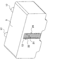
図1ないし図7に示す電源装置は、一端に凸部電極6を有する複数の素電池1をケース3に収納している。ケース3内には熱交換フィン13を配設している。熱交換フィン13は、両面に素電池1の端部を熱結合状態で連結する電池保持部14を設けている。熱交換フィン13の電池保持部14には、素電池1の一端部であって凸部電極6を設けている端部と反対側の底部を連結している。熱交換フィン13は、電池保持部14に連結している素電池1を底部から冷却する。
In the power supply device shown in FIGS. 1 to 7, a plurality of
図の電源装置は、ケース3に収納する素電池1をリチウムイオン二次電池の円筒型電池とする。リチウムイオン二次電池は出力電圧が高いので、直列に接続する個数を少なくして、電源装置の出力電圧を高くできる。車両用の電源装置は、たとえば、円筒型電池を直列に接続する個数を調整して、出力電圧を100〜300Vとする。ただし、本発明の電源装置は、素電池をリチウムイオン二次電池に特定しない。素電池には、ニッケル水素電池やニッケルカドミウム電池等の全ての二次電池とすることができる。また、素電池を円筒型電池にも特定しない。素電池には、角形電池も使用できるからである。
In the illustrated power supply apparatus, the
素電池1は、外装缶4の開口部を封口板5で閉塞して、封口板5に凸部電極6を設けている。外装缶4と封口板5は金属板で、外装缶4と封口板とを、かしめ加工して気密に連結し、あるいはレーザー溶接して気密に連結している。外装缶4をかしめ加工して開口部を閉塞する封口板5は、絶縁性のパッキン(図示せず)を介して外装缶4の開口部を気密に閉塞する。この素電池1は、外装缶4を負極として封口板5を正極とし、あるいは反対に外装缶を正極として封口板を負極とする。外装缶の開口部にレーザー溶接される封口板は、絶縁材を介して凸部電極を固定している。この素電池も、凸部電極を正極として外装缶を負極とし、あるいは反対に凸部電極を負極として外装缶を正極としている。さらに、図に示す素電池1は、凸部電極6側の端部に絶縁カバー7を設けている。この絶縁カバー7は、隣接する素電池1同士を絶縁する。ただ、この絶縁カバーは、必ずしも必要ではない。後述するホルダー25にて、隣接する素電池1を絶縁状態で連結できるからである。
In the
図の電源装置は、ケース3内に3段に素電池1を並べて収納し、各段には4本の素電池1を配列している。素電池1は、熱交換フィン13の両側に配設されるので、全体で24本の素電池1を収納している。本発明の電源装置は、ケースに収納する素電池の個数を特定しない。ケースに収納する素電池の個数を多くして、出力電圧を高くでき、また素電池の個数を少なくして出力電圧を低くできる。
In the power supply apparatus shown in the figure,
ケース3は、熱交換フィン13の両側に密閉室15を設けて、ここに素電池1を収納している。熱交換フィン13の両側に設けている密閉室15は、素電池1から排出される電解液を貯めるドレイン16を底部に設けている。ドレイン16は、ケース3の底部を下方に突出させて、ここに貯溜される電解液が素電池1に接触するのを防止する。この構造の電源装置は、素電池1から排出される電解液を底部に流下させてケース3のドレイン16に貯めるので、電解液に起因する弊害、たとえば電解液によるショートや腐食等の弊害を防止できる。
The
さらに、図の電源装置は、ケース3内の密閉室15に消火器17を連結している。消火器17は、素電池1からの排出物で密閉室15の圧力が設定圧力よりも高くなると、密閉室15に消火剤を噴射する。消火器は、電池に開弁センサーを設けて、この開弁センサーで消火剤を噴射することもできる。消火器17は、圧縮ボンベに炭酸ガス等の不活性ガスを充填している。この消火器17は、充填している炭酸ガス等の不活性なガス圧で、炭酸水素ナトリウムを主成分とする粉末等の消火剤をケース3の密閉室15に噴射する。ただ、消火器17が噴射する消火剤は、炭酸水素ナトリウムを主成分とする粉末には特定されず、消火剤には、電池を収納する密閉室15に噴射して、電池から排出されるガス等の流体を消火できるすべてのものを使用できる。
Further, the power supply apparatus shown in the figure has a
さらに、図に示すケース3は、ドレイン16の底面にガス排出弁18を設けている。ガス排出弁18は、密閉室15の内圧が設定圧力よりも高くなると開弁される。図のケース3は、ドレイン16の底部に貫通孔19を設け、この貫通孔19を設定圧力で破壊されるシート20で閉塞してガス排出弁18としている。ガス排出弁18は、素電池1から電解液が噴射されて密閉室15の圧力が設定圧力に上昇すると開弁して、素電池1の排出物をケース3の外部に排気する。また、ガス排出弁18が開弁される状態で、消火器17が消火剤を密閉室15に噴射する。この状態で、素電池1の排出物は、消火剤で密閉室15から外部に強制的に排出される。この構造の電源装置は、素電池1から発火性のガスが排出されても、これを外部に排出して安全性を著しく向上できる。
Further, the
ケース3の密閉室15に消火器17を連結し、さらにガス排出弁18を設けている電源装置は、消火器17が密閉室15に消火剤を噴射した後にガス排出弁18を開弁し、あるいはガス排出弁18を開弁した後に消火器17から消火剤を噴射し、あるいはまた、ガス排出弁18を開弁するときに消火器17から消火剤を噴射する。消火器17が密閉室15に消火剤を噴射した後にガス排出弁18を開弁する電源装置は、消火器17が消火剤を噴射する設定圧力よりも、ガス排出弁18が開弁する設定圧力を高く設定する。ガス排出弁18を開弁した後に消火器17から消火剤を噴射する電源装置は、ガス排出弁18の開弁を検出した後、消火器17を制御して、消火剤を噴射させる。また、ガス排出弁18を開弁するときに消火器17から消火剤を噴射する電源装置は、密閉室15の圧力を圧力センサーで検出し、この圧力センサーでガス排出弁18と消火器17の両方を制御し、ガス排出弁18を開弁するときに消火器17から消火剤を噴射させる。
The power supply device in which the
図のケース3は、中央に熱交換フィン13を配設して、熱交換フィン13でケース3内をふたつの密閉室15に区画している。熱交換フィン13は、各々の素電池1を底部から冷却する位置に配置する。熱交換フィン13は、アルミニウムや銅等の導電性に優れた金属で製作される。図の熱交換フィン13は、冷却用の空気を透過させるダクト21を両端面に貫通するように設けている。この熱交換フィン13は、ダクト21に送風される空気で強制的に冷却されて、これに冷却している素電池1を冷却する。
The
図7と図8に示す熱交換フィン13は、素電池1を加温するヒーター22を設けている。ヒーター22は素電池1を加温する。この電源装置は、極寒の地域で使用される車両に搭載されて、電池の性能を向上できる。寒冷地で使用される車両用の電源装置は、車両をスタートさせるときに電池温度が著しく低く、たとえば−20℃以下となることがある。この状態で、電池は電気性能が著しく低下する。ヒーター22で熱交換フィン13を加温し、熱交換フィン13で素電池1を加温する電源装置は、電池を所定の温度に加温して使用できる。
The
図の熱交換フィン13は、ヒーター22を挿通する貫通孔23を設けており、この貫通孔23にヒーター22を挿通している。この熱交換フィン13は、ダクト21の両側に所定の間隔で貫通孔23を設けている。ヒーター22は、絶縁して熱交換フィン13の貫通孔23に挿通される。ヒーター22は、熱交換フィン13の外部で直列に接続されて、熱交換フィン13を均一に加温する。ヒーター22は、制御回路(図示せず)に制御されて、熱交換フィン13を設定温度に加温する。
The illustrated
熱交換フィン13は、その両側面に、素電池1を連結する電池保持部14を設けている。図の熱交換フィン13の電池保持部14は、素電池1の底部を挿入する嵌合凹部である。この電池保持部14は、素電池1の底部を嵌入して定位置に保持する。また、嵌合凹部の内面と素電池1表面とが接触して、熱結合状態に連結される。熱交換フィン13と素電池1とは熱結合状態に連結されるが、絶縁して連結される。熱交換フィン13と素電池1を絶縁するために、熱交換フィン13の電池保持部14の内面に絶縁層を設け、あるいは素電池1の底部表面に絶縁層を設け、あるいはまた、電池保持部14の内面と素電池1の表面の両面に絶縁層を設ける。絶縁層は、厚すぎると熱伝導を悪くする。したがって、熱交換フィン13と素電池1との間の絶縁層は、熱伝導を阻害しない状態で両者を絶縁する。
The
図の電源装置は素電池1を円筒型電池とするので、電池保持部14を円柱状の嵌合凹部としている。さらに、電池保持部14である嵌合凹部の内径は、素電池1の外径にほぼ等しくしている。この熱交換フィン13は、素電池1を嵌合凹部に挿入して、素電池1の外周を電池保持部14の内面に接触できる。この連結構造は、熱交換フィン13と素電池1との接触面積が大きく、熱交換フィン13と素電池1との熱伝導を良くして、熱交換フィン13で素電池1を効率よく冷却でき、また加温できる。
In the illustrated power supply device, the
素電池1は、素電池1の一端部であって凸部電極6を設けている端部と反対側の底部を電池保持部14の嵌合凹部に入れて連結している。素電池1の底部は、バスバー等を連結する必要がない。素電池1が凸部電極6側に接続しているバスバーで連結されるからである。したがって、熱交換フィン13の電池保持部14に、バスバーを連結しない素電池1の底部を入れて連結される。この構造は、素電池1と熱交換フィン13との接触面積を大きくできると共に、電池保持部14の底部にバスバーを引き出す穴等を開口する必要がなく、熱交換フィン13でもってケース3内に閉鎖された密閉室15を設けることができる。
The
図の電源装置は、熱交換フィン13の両側に3×4個の電池保持部14を設けて、各々の電池保持部14に素電池1の底部を挿入して連結している。この電源装置は、熱交換フィン13の電池保持部14に素電池1の底部を入れて定位置に配置するので、熱交換フィン13の両側に設ける電池保持部14の個数を調整して、両側に連結する素電池1の数を調整できる。
In the illustrated power supply device, 3 × 4
熱交換フィン13は、両側に密閉室15を設けるので、外形をケース3の内形に等しくして、外周面をケース3の内面に当接させている。熱交換フィン13は、ダクト21に空気を強制送風して冷却できるように、ケース3には送風窓24を開口している。送風窓24は、ダクト21をケース3の外部に表出させる位置に開口されて、ここから熱交換フィン13のダクト21に空気を強制送風する。
Since the
素電池1は、底部を熱交換フィン13の電池保持部14に入れて定位置に保持し、凸部電極6側の端部を、ホルダー25でケース3内の定位置に保持している。ホルダー25は、図7に示すように、素電池1の凸部電極6側の端部を両側から挟着して、定位置に配置する。ホルダー25は、素電池1の端部を嵌入できる半円形の凹部溝26を設けている。上下の素電池1の間に配設されるホルダー25は、上下の両側面に凹部溝26を設けており、最上段のホルダー25は下面に、最下段のホルダー25は上面に凹部溝26を設けている。図の電源装置は、3段に素電池1を配設するので、4つに分離されたホルダー25で、素電池1を上下から挟着している。全ての素電池1を挟着するように連結されたホルダー25は、外形をケース3の内形に等しくして、ケース3内の定位置に配置して固定される。ただ、素電池1を挟着するホルダー25は、ケース3との間に隙間(図示せず)を設けている。この隙間は、素電池1の排出物を通過させて、底部のドレイン16に流下させる。素電池1は、凸部電極6側の端部に安全弁(図示せず)を内蔵するので、内圧が上昇して安全弁が開弁すると、凸部電極6側の端部から電解液が排出される。排出されたガスや液体は、ホルダー25とケース3との間に設けた隙間を通過し、あるいは素電池1を挟着しているホルダー25の間の隙間を通過し、あるいはまた、ホルダー25と素電池1との間の隙間を通過して、ドレイン16に貯えられる。
In the
素電池1の端部を保持する熱交換フィン13とホルダー25は、止ネジ(図示せず)を介して、あるいは嵌着構造でケース3の定位置に固定されて、複数の素電池1を所定の位置に配置する。
The
熱交換フィン13とホルダー25で定位置に配置される素電池1は、凸部電極6にバスバーを連結し、このバスバーでもって隣接する素電池1に接続される。素電池1を接続するバスバーは、図9ないし図14に示している。これ等のバスバーは、隣接する素電池1を直列に接続する。
The
図9と図10に示すバスバー2は、素電池1である円筒型電池の上端部の封口板5に接続される上端連結部8と、この上端連結部8を連結している円筒型電池に隣接して配置される円筒型電池の外装缶4に接続される外装缶連結部9とからなる。バスバー2は、上端連結部8と外装缶連結部9を互いに直交するように連結する形状として、全体をL字状としている。
The
バスバー2の外装缶連結部9は、2分岐された分岐アーム9Aである。分岐アーム9Aは、図11と図12に示すように、円筒型電池の谷間に配置されて、隣接する円筒型電池の間に挟着される位置に配置されない。この構造は、円筒型電池の間に、分岐アーム9Aを配置する隙間を設ける必要がない。隣接する円筒型電池を互いに接近して配置してできる谷間のスペースに分岐アーム9Aを配置するからである。
The outer
図のバスバー2は、2本の分岐アーム9Aの上端をL字状に折曲して、折曲端を上端連結部8に連結する形状としている。このバスバー2は、弾性変形できる金属板で製作して、耐振性を向上できる。バスバー2が弾性変形して振動を吸収するからである。弾性変形できるバスバー2は、たとえば、鉄や鉄合金の表面を、銅、ニッケル、クローム等のメッキをした金属板を使用する。ただし、バスバーには、銅や銅合金を使用し、さらにその表面をメッキして、電気抵抗を小さくすることもできる。
The
バスバー2は、抵抗溶接であるスポット溶接で外装缶4に連結される。図のバスバー2は、外装缶連結部9の下端部に、外装缶4の表面に抵抗溶接する接続片10を設けている。接続片10は、所定の幅と長さを有し、かつ外装缶4の表面に沿う形状に湾曲されている。この接続片10は、分岐アーム9Aの内側からV字状に折曲されて、外装缶4の表面に沿うようにしている。このバスバー2は、接続片10をスポット溶接して、外装缶4に接続される。
The
上端連結部8は、円筒型電池の封口板5に設けている凸部電極6に連結される。図の上端連結部8は、凸部電極6のボルト6Aの貫通孔8Aを設けている。この上端連結部8は、貫通孔8Aにボルト6Aを挿通し、ボルト6Aにナット30を締め付けて、凸部電極6に接続される。この構造は、図9に示すように、外装缶連結部9の分岐アーム9Aを円筒型電池に連結し、円筒型電池に連結されたバスバー2の上端連結部8の貫通孔8Aに、隣接する円筒型電池のボルト6Aを挿通する状態で円筒型電池を並べ、ボルト6Aにナット30を締め付けて、円筒型電池を特定の配列に固定できる。バスバー2の一端をボルト6Aとナット30で円筒型電池に連結している電源装置は、ナット30を外して円筒型電池を分離できる。このため、メンテナンスのときに、特定の円筒型電池を交換できる。また、簡単に能率よく組み立てできる特徴もある。ただし、バスバー2の上端連結部8は、抵抗溶接やレーザー溶接等の方法で溶着して封口板5に連結することができる。上端連結部が溶着される円筒型電池は、凸部電極を設けることなく、封口板5に直接に溶着することもできる。
The upper
さらに、図13と図14に示すバスバー2は、円筒型電池の温度を検出する温度センサー11を固定している。温度センサー11は、たとえば、サーミスタである。サーミスタである温度センサー11は、バスバー2を介して熱電導される円筒型電池の温度を、抵抗値の変化として検出する。ただ、温度センサーには、サーミスタに代わって、温度を電気的に検出できる全ての素子を使用できる。図のバスバー2は、上端連結部8の上面に温度センサー11を固定している。温度センサー11は、熱伝導に優れた接着剤を介して上端連結部8に接着している。このように、上端連結部8の上面に温度センサー11を配置する構造は、外装缶4の表面に温度センサーを貼り付ける従来の構造に比較して、温度センサー11の配線(図示せず)を容易にできる特長がある。さらに、バスバー2に配置される温度センサー11で円筒型電池の温度を検出する構造は、ひとつの温度センサー11で2個の円筒型電池の温度を検出するので、温度センサー11の数を半減できる特長もある。
Further, the
さらに、図13と図14に示すバスバー2は、上端連結部8の上面に、温度センサー11を案内する凹部12を設けており、この凹部12に温度センサー11を配置している。このように、凹部12に温度センサー11を配置して固定する構造は、温度センサー11を正確な位置に位置決めしながら配置できると共に、振動等によって、温度センサー11の位置がずれるのを有効に防止できる特長がある。
Further, the
素電池1は、バスバーで直列に接続された状態で、ホルダー25に挟着される。したがって、ホルダー25はバスバーを案内する凹部(図示せず)を設けており、凹部にバスバーを案内して、素電池1を挟着する。
The
図2に示す電源装置は、回路基板27を収納している。図の電源装置は、ケース3の上面に、回路基板27をポッテングして樹脂29に固定している。回路基板27は、素電池1の充放電をコントロールする制御回路を実現する電子部品を実装する。回路基板27に実装される制御回路は、素電池1の電圧を検出し、あるいは電圧と温度を検出し、さらに電圧と温度と充放電の電流を検出して、充放電の電流をコントロールする。たとえば、制御回路は、何れかの素電池1の電圧が最高電圧よりも高くなると、充電電流を遮断し、また最低電圧よりも低くなると放電電流を遮断する。また、電池温度が最高温度よりも高くなると、充放電の電流を遮断し、あるいは制限する。また、充放電の電流を積載して素電池1の残容量を演算し、残容量が満充電となると充電電流を遮断し、また残容量が0になると放電電流を遮断する。
The power supply device shown in FIG. 2 houses a
回路基板27は、リード線を介して各々の素電池1の凸部電極6に接続される。図の電源装置は、フレキシブル基板28に設けたリード線を介して、素電池1の凸部電極6を回路基板27に接続している。
The
1…素電池
2…バスバー
3…ケース
4…外装缶
5…封口板
6…凸部電極 6A…ボルト
7…絶縁カバー
8…上端連結部 8A…貫通孔
9…外装缶連結部 9A…分岐アーム
10…接続片
11…温度センサー
12…凹部
13…熱交換フィン
14…電池保持部
15…密閉室
16…ドレイン
17…消火器
18…ガス排出弁
19…貫通孔
20…シート
21…ダクト
22…ヒーター
23…貫通孔
24…送風窓
25…ホルダー
26…凹部溝
27…回路基板
28…フレキシブル基板
29…樹脂
30…ナット
DESCRIPTION OF
Claims (7)
前記ケース(3)内に熱交換フィン(13)を配設しており、この熱交換フィン(13)は両面に前記素電池(1)の端部を熱結合状態で連結する電池保持部(14)を設けており、前記熱交換フィン(13)の電池保持部(14)には、前記素電池(1)の一端部であって凸部電極(6)を設けている端部と反対側の底部を連結しており、
前記熱交換フィン(13)でもって、電池保持部(14)に連結している素電池(1)を底部から冷却するようにしてなる電源装置。 A power supply device storing a plurality of unit cells (1) having a convex electrode (6) at one end in a case (3),
A heat exchange fin (13) is disposed in the case (3), and the heat exchange fin (13) is a battery holding part that connects the ends of the unit cells (1) to both surfaces in a thermally coupled state ( 14), and the battery holding part (14) of the heat exchange fin (13) is opposite to the end part of the unit cell (1), which is provided with the convex electrode (6). Connecting the bottom of the side,
A power supply device configured to cool the unit cell (1) connected to the battery holding portion (14) from the bottom with the heat exchange fin (13).
The inside of the case (3) is a sealed chamber (15), and a fire extinguisher (17) is connected to the sealed chamber (15), and the pressure in the sealed chamber (15) is reduced by discharge from the unit cell (1). The power supply device according to claim 5, wherein when the pressure becomes higher than a set pressure, the fire extinguisher (17) injects a fire extinguisher into the sealed chamber (15).
Priority Applications (1)
| Application Number | Priority Date | Filing Date | Title |
|---|---|---|---|
| JP2005283115A JP4902164B2 (en) | 2005-09-28 | 2005-09-28 | Power supply |
Applications Claiming Priority (1)
| Application Number | Priority Date | Filing Date | Title |
|---|---|---|---|
| JP2005283115A JP4902164B2 (en) | 2005-09-28 | 2005-09-28 | Power supply |
Publications (2)
| Publication Number | Publication Date |
|---|---|
| JP2007095483A JP2007095483A (en) | 2007-04-12 |
| JP4902164B2 true JP4902164B2 (en) | 2012-03-21 |
Family
ID=37980928
Family Applications (1)
| Application Number | Title | Priority Date | Filing Date |
|---|---|---|---|
| JP2005283115A Expired - Fee Related JP4902164B2 (en) | 2005-09-28 | 2005-09-28 | Power supply |
Country Status (1)
| Country | Link |
|---|---|
| JP (1) | JP4902164B2 (en) |
Families Citing this family (37)
| Publication number | Priority date | Publication date | Assignee | Title |
|---|---|---|---|---|
| JP5093462B2 (en) * | 2007-06-14 | 2012-12-12 | Necエナジーデバイス株式会社 | Tab terminal and battery using the same |
| JP2009004237A (en) * | 2007-06-21 | 2009-01-08 | Toyota Motor Corp | Power storage device and vehicle |
| JP4788674B2 (en) * | 2007-07-05 | 2011-10-05 | トヨタ自動車株式会社 | Power supply |
| JP5150193B2 (en) * | 2007-10-15 | 2013-02-20 | シャープ株式会社 | Battery pack |
| JP5256821B2 (en) * | 2008-04-01 | 2013-08-07 | パナソニック株式会社 | Connection structure between batteries |
| JP5155772B2 (en) * | 2008-08-19 | 2013-03-06 | 三菱重工業株式会社 | Battery pack structure |
| KR20100062576A (en) | 2008-12-02 | 2010-06-10 | 삼성전자주식회사 | Cooling device of battery pack |
| JP4807595B2 (en) * | 2008-12-12 | 2011-11-02 | 本田技研工業株式会社 | Battery holding device |
| JP5185876B2 (en) * | 2009-03-31 | 2013-04-17 | 本田技研工業株式会社 | Battery assembly |
| JP5451211B2 (en) | 2009-06-26 | 2014-03-26 | パナソニック株式会社 | Power storage unit |
| DE102009028271A1 (en) * | 2009-08-06 | 2011-02-10 | Robert Bosch Gmbh | Protection device for a test facility |
| SE534266C2 (en) | 2009-11-20 | 2011-06-21 | Scania Cv Ab | Cooling arrangement for at least one battery in a vehicle |
| JP2011249225A (en) * | 2010-05-28 | 2011-12-08 | Nippon Telegr & Teleph Corp <Ntt> | Storage battery module |
| JP2011249224A (en) * | 2010-05-28 | 2011-12-08 | Nippon Telegr & Teleph Corp <Ntt> | Storage battery module |
| JP2011253746A (en) * | 2010-06-03 | 2011-12-15 | Nippon Telegr & Teleph Corp <Ntt> | Storage battery module and storage battery system |
| JP5343048B2 (en) | 2010-07-29 | 2013-11-13 | 日立ビークルエナジー株式会社 | Power storage module and power storage device |
| FR2967823B1 (en) * | 2010-11-19 | 2015-05-22 | Renault Sa | BATTERY OF ACCUMULATORS AND METHOD FOR DETECTING CORRESPONDING HEATING |
| DE102011075318A1 (en) * | 2011-05-05 | 2012-11-08 | Sb Limotive Company Ltd. | Battery housing for lithium-ion cells |
| US9450219B2 (en) * | 2011-09-15 | 2016-09-20 | Samsung Sdi Co., Ltd. | Battery module |
| JP5757502B2 (en) * | 2011-09-27 | 2015-07-29 | 古河電気工業株式会社 | Battery temperature control unit and battery temperature control device |
| JP6017221B2 (en) * | 2012-08-09 | 2016-10-26 | ホーチキ株式会社 | Fire extinguishing system for electric vehicles |
| FR2998841A1 (en) * | 2012-12-05 | 2014-06-06 | Renault Sa | Device for renewal of air in support and protection housing of electric battery of car, has battery positioned in housing so as to allow air, which is injected into housing by duct to be rejected outside by electrolyte discharge pipe |
| JP5965348B2 (en) * | 2013-04-11 | 2016-08-03 | 株式会社オートネットワーク技術研究所 | Power storage module |
| JP5965350B2 (en) * | 2013-04-18 | 2016-08-03 | 株式会社オートネットワーク技術研究所 | Power storage module |
| KR101486928B1 (en) * | 2013-04-29 | 2015-02-04 | 주식회사 엘지화학 | Battery module assembly for vehicle's battery pack |
| WO2014178569A1 (en) * | 2013-04-29 | 2014-11-06 | 주식회사 엘지화학 | Battery pack case for vehicle |
| JP6070672B2 (en) * | 2014-10-21 | 2017-02-01 | トヨタ自動車株式会社 | Power storage module |
| JP6248972B2 (en) * | 2015-03-23 | 2017-12-20 | トヨタ自動車株式会社 | Battery pack |
| JP6156421B2 (en) * | 2015-03-23 | 2017-07-05 | トヨタ自動車株式会社 | Battery pack |
| JP6256397B2 (en) * | 2015-03-23 | 2018-01-10 | トヨタ自動車株式会社 | Battery pack |
| JP6536254B2 (en) * | 2015-07-29 | 2019-07-03 | 株式会社豊田自動織機 | Battery pack |
| JP2017189068A (en) * | 2016-04-08 | 2017-10-12 | 株式会社東芝 | Storage battery unit for electric vehicle |
| KR102263763B1 (en) * | 2018-01-17 | 2021-06-09 | 주식회사 엘지에너지솔루션 | Mfultilayer cylindrical battery module with heat dissipation and chain ignition prevention structure and Battery Pack including the same |
| DE102018202114A1 (en) * | 2018-02-12 | 2019-08-14 | Airbus Defence and Space GmbH | Battery assembly for the structural integration of batteries in a vehicle |
| WO2019186969A1 (en) * | 2018-03-29 | 2019-10-03 | 株式会社 東芝 | Battery pack |
| GB2576360A (en) * | 2018-08-16 | 2020-02-19 | Hyperdrive Innovation Ltd | Method and apparatus |
| CN118073714A (en) * | 2024-04-17 | 2024-05-24 | 北京航空航天大学 | Battery module |
Family Cites Families (9)
| Publication number | Priority date | Publication date | Assignee | Title |
|---|---|---|---|---|
| JP3242153B2 (en) * | 1992-06-08 | 2001-12-25 | 本田技研工業株式会社 | Battery module temperature control structure |
| JPH10302847A (en) * | 1997-04-25 | 1998-11-13 | Nissan Motor Co Ltd | Battery structure of electric vehicle |
| JP4164212B2 (en) * | 1999-11-18 | 2008-10-15 | 株式会社日立製作所 | Battery module and power supply device |
| JP2001257006A (en) * | 2000-03-13 | 2001-09-21 | Japan Storage Battery Co Ltd | Battery system, industrial system equipped with battery system and mobile structure |
| JP3914707B2 (en) * | 2000-06-19 | 2007-05-16 | 本田技研工業株式会社 | Storage element and holding structure thereof |
| JP4717990B2 (en) * | 2000-09-13 | 2011-07-06 | パナソニック株式会社 | Battery pack |
| JP2002289265A (en) * | 2001-03-23 | 2002-10-04 | Mitsubishi Heavy Ind Ltd | Lithium secondary battery monitoring device |
| JP2002289159A (en) * | 2001-03-26 | 2002-10-04 | Toshiba Corp | Nonaqueous electrolyte secondary battery pack |
| JP2005310449A (en) * | 2004-04-19 | 2005-11-04 | Fujitsu Component Ltd | Battery pack |
-
2005
- 2005-09-28 JP JP2005283115A patent/JP4902164B2/en not_active Expired - Fee Related
Also Published As
| Publication number | Publication date |
|---|---|
| JP2007095483A (en) | 2007-04-12 |
Similar Documents
| Publication | Publication Date | Title |
|---|---|---|
| JP4902164B2 (en) | Power supply | |
| JP4812345B2 (en) | Power supply | |
| JP5209036B2 (en) | Battery assembly, electric vehicle, and battery housing | |
| JP4960042B2 (en) | Battery assembly with heater | |
| JP4525695B2 (en) | Power storage device | |
| JP4815026B2 (en) | Battery module and battery pack using the same | |
| JP6540628B2 (en) | Battery pack | |
| US8679660B2 (en) | Electric power storage apparatus | |
| JP2013214354A (en) | Battery module | |
| KR101501026B1 (en) | Battery Module with Excellent Cooling Efficiency and Compact Structure | |
| JP2008053149A5 (en) | ||
| KR20140039350A (en) | Battery module of improved cooling efficiency | |
| KR20130125341A (en) | Battery module with cooling structure of high efficiency | |
| JP2014514691A (en) | Energy storage device, energy storage cell and heat conducting element having elastic means | |
| JP2015172997A (en) | Battery system, and vehicle and power storage device comprising battery system | |
| US20220231375A1 (en) | A battery module | |
| JP2013030384A (en) | Battery block and battery pack | |
| KR20190042215A (en) | Secondary Battery Pouch-Type Case Having Gas Discharge Port | |
| CN211789391U (en) | New energy automobile battery package | |
| JP2009158281A (en) | Battery pack | |
| JP2010061988A (en) | Storage battery device | |
| JP2006250734A (en) | Temperature detector for battery | |
| JP2010015958A (en) | Power storage module and its manufacturing method | |
| WO2014010437A1 (en) | Power source device and vehicle provided with said power source device | |
| EP4416789A1 (en) | Battery cell pack for electric vehicle |
Legal Events
| Date | Code | Title | Description |
|---|---|---|---|
| A621 | Written request for application examination |
Free format text: JAPANESE INTERMEDIATE CODE: A621 Effective date: 20080508 |
|
| A977 | Report on retrieval |
Free format text: JAPANESE INTERMEDIATE CODE: A971007 Effective date: 20111024 |
|
| TRDD | Decision of grant or rejection written | ||
| A01 | Written decision to grant a patent or to grant a registration (utility model) |
Free format text: JAPANESE INTERMEDIATE CODE: A01 Effective date: 20111206 |
|
| A01 | Written decision to grant a patent or to grant a registration (utility model) |
Free format text: JAPANESE INTERMEDIATE CODE: A01 |
|
| A61 | First payment of annual fees (during grant procedure) |
Free format text: JAPANESE INTERMEDIATE CODE: A61 Effective date: 20111228 |
|
| FPAY | Renewal fee payment (event date is renewal date of database) |
Free format text: PAYMENT UNTIL: 20150113 Year of fee payment: 3 |
|
| LAPS | Cancellation because of no payment of annual fees |