JP6070672B2 - Power storage module - Google Patents
Power storage module Download PDFInfo
- Publication number
- JP6070672B2 JP6070672B2 JP2014214697A JP2014214697A JP6070672B2 JP 6070672 B2 JP6070672 B2 JP 6070672B2 JP 2014214697 A JP2014214697 A JP 2014214697A JP 2014214697 A JP2014214697 A JP 2014214697A JP 6070672 B2 JP6070672 B2 JP 6070672B2
- Authority
- JP
- Japan
- Prior art keywords
- holder
- battery
- power storage
- temperature
- heater
- Prior art date
- Legal status (The legal status is an assumption and is not a legal conclusion. Google has not performed a legal analysis and makes no representation as to the accuracy of the status listed.)
- Active
Links
- 238000003780 insertion Methods 0.000 claims description 6
- 230000037431 insertion Effects 0.000 claims description 6
- 238000000638 solvent extraction Methods 0.000 claims 1
- 210000004027 cell Anatomy 0.000 description 144
- 230000007423 decrease Effects 0.000 description 8
- 238000010438 heat treatment Methods 0.000 description 7
- 238000010248 power generation Methods 0.000 description 4
- 239000011347 resin Substances 0.000 description 4
- 229920005989 resin Polymers 0.000 description 4
- 238000010586 diagram Methods 0.000 description 3
- 239000011810 insulating material Substances 0.000 description 3
- 229910052751 metal Inorganic materials 0.000 description 3
- 239000002184 metal Substances 0.000 description 3
- 238000012986 modification Methods 0.000 description 3
- 230000004048 modification Effects 0.000 description 3
- 239000004020 conductor Substances 0.000 description 2
- 238000001816 cooling Methods 0.000 description 2
- 230000006866 deterioration Effects 0.000 description 2
- HBBGRARXTFLTSG-UHFFFAOYSA-N Lithium ion Chemical compound [Li+] HBBGRARXTFLTSG-UHFFFAOYSA-N 0.000 description 1
- 229910052782 aluminium Inorganic materials 0.000 description 1
- XAGFODPZIPBFFR-UHFFFAOYSA-N aluminium Chemical compound [Al] XAGFODPZIPBFFR-UHFFFAOYSA-N 0.000 description 1
- 239000003990 capacitor Substances 0.000 description 1
- 210000005056 cell body Anatomy 0.000 description 1
- 238000007599 discharging Methods 0.000 description 1
- 239000012212 insulator Substances 0.000 description 1
- 229910001416 lithium ion Inorganic materials 0.000 description 1
- 239000000463 material Substances 0.000 description 1
- 239000000155 melt Substances 0.000 description 1
- 229910052987 metal hydride Inorganic materials 0.000 description 1
- 239000007769 metal material Substances 0.000 description 1
- 229910052759 nickel Inorganic materials 0.000 description 1
- PXHVJJICTQNCMI-UHFFFAOYSA-N nickel Substances [Ni] PXHVJJICTQNCMI-UHFFFAOYSA-N 0.000 description 1
- -1 nickel metal hydride Chemical class 0.000 description 1
- 230000035515 penetration Effects 0.000 description 1
- 230000002093 peripheral effect Effects 0.000 description 1
- 238000003825 pressing Methods 0.000 description 1
- 238000004080 punching Methods 0.000 description 1
- 230000001172 regenerating effect Effects 0.000 description 1
- 230000000630 rising effect Effects 0.000 description 1
Images


Classifications
-
- H—ELECTRICITY
- H01—ELECTRIC ELEMENTS
- H01M—PROCESSES OR MEANS, e.g. BATTERIES, FOR THE DIRECT CONVERSION OF CHEMICAL ENERGY INTO ELECTRICAL ENERGY
- H01M10/00—Secondary cells; Manufacture thereof
- H01M10/60—Heating or cooling; Temperature control
- H01M10/61—Types of temperature control
- H01M10/615—Heating or keeping warm
-
- H—ELECTRICITY
- H01—ELECTRIC ELEMENTS
- H01G—CAPACITORS; CAPACITORS, RECTIFIERS, DETECTORS, SWITCHING DEVICES, LIGHT-SENSITIVE OR TEMPERATURE-SENSITIVE DEVICES OF THE ELECTROLYTIC TYPE
- H01G11/00—Hybrid capacitors, i.e. capacitors having different positive and negative electrodes; Electric double-layer [EDL] capacitors; Processes for the manufacture thereof or of parts thereof
- H01G11/10—Multiple hybrid or EDL capacitors, e.g. arrays or modules
-
- H—ELECTRICITY
- H01—ELECTRIC ELEMENTS
- H01G—CAPACITORS; CAPACITORS, RECTIFIERS, DETECTORS, SWITCHING DEVICES, LIGHT-SENSITIVE OR TEMPERATURE-SENSITIVE DEVICES OF THE ELECTROLYTIC TYPE
- H01G11/00—Hybrid capacitors, i.e. capacitors having different positive and negative electrodes; Electric double-layer [EDL] capacitors; Processes for the manufacture thereof or of parts thereof
- H01G11/14—Arrangements or processes for adjusting or protecting hybrid or EDL capacitors
- H01G11/18—Arrangements or processes for adjusting or protecting hybrid or EDL capacitors against thermal overloads, e.g. heating, cooling or ventilating
-
- H—ELECTRICITY
- H01—ELECTRIC ELEMENTS
- H01G—CAPACITORS; CAPACITORS, RECTIFIERS, DETECTORS, SWITCHING DEVICES, LIGHT-SENSITIVE OR TEMPERATURE-SENSITIVE DEVICES OF THE ELECTROLYTIC TYPE
- H01G11/00—Hybrid capacitors, i.e. capacitors having different positive and negative electrodes; Electric double-layer [EDL] capacitors; Processes for the manufacture thereof or of parts thereof
- H01G11/74—Terminals, e.g. extensions of current collectors
- H01G11/76—Terminals, e.g. extensions of current collectors specially adapted for integration in multiple or stacked hybrid or EDL capacitors
-
- H—ELECTRICITY
- H01—ELECTRIC ELEMENTS
- H01G—CAPACITORS; CAPACITORS, RECTIFIERS, DETECTORS, SWITCHING DEVICES, LIGHT-SENSITIVE OR TEMPERATURE-SENSITIVE DEVICES OF THE ELECTROLYTIC TYPE
- H01G11/00—Hybrid capacitors, i.e. capacitors having different positive and negative electrodes; Electric double-layer [EDL] capacitors; Processes for the manufacture thereof or of parts thereof
- H01G11/78—Cases; Housings; Encapsulations; Mountings
- H01G11/82—Fixing or assembling a capacitive element in a housing, e.g. mounting electrodes, current collectors or terminals in containers or encapsulations
-
- H—ELECTRICITY
- H01—ELECTRIC ELEMENTS
- H01M—PROCESSES OR MEANS, e.g. BATTERIES, FOR THE DIRECT CONVERSION OF CHEMICAL ENERGY INTO ELECTRICAL ENERGY
- H01M10/00—Secondary cells; Manufacture thereof
- H01M10/60—Heating or cooling; Temperature control
- H01M10/62—Heating or cooling; Temperature control specially adapted for specific applications
- H01M10/625—Vehicles
-
- H—ELECTRICITY
- H01—ELECTRIC ELEMENTS
- H01M—PROCESSES OR MEANS, e.g. BATTERIES, FOR THE DIRECT CONVERSION OF CHEMICAL ENERGY INTO ELECTRICAL ENERGY
- H01M10/00—Secondary cells; Manufacture thereof
- H01M10/60—Heating or cooling; Temperature control
- H01M10/65—Means for temperature control structurally associated with the cells
- H01M10/657—Means for temperature control structurally associated with the cells by electric or electromagnetic means
-
- H—ELECTRICITY
- H01—ELECTRIC ELEMENTS
- H01M—PROCESSES OR MEANS, e.g. BATTERIES, FOR THE DIRECT CONVERSION OF CHEMICAL ENERGY INTO ELECTRICAL ENERGY
- H01M50/00—Constructional details or processes of manufacture of the non-active parts of electrochemical cells other than fuel cells, e.g. hybrid cells
- H01M50/20—Mountings; Secondary casings or frames; Racks, modules or packs; Suspension devices; Shock absorbers; Transport or carrying devices; Holders
- H01M50/204—Racks, modules or packs for multiple batteries or multiple cells
- H01M50/207—Racks, modules or packs for multiple batteries or multiple cells characterised by their shape
- H01M50/213—Racks, modules or packs for multiple batteries or multiple cells characterised by their shape adapted for cells having curved cross-section, e.g. round or elliptic
-
- H—ELECTRICITY
- H01—ELECTRIC ELEMENTS
- H01M—PROCESSES OR MEANS, e.g. BATTERIES, FOR THE DIRECT CONVERSION OF CHEMICAL ENERGY INTO ELECTRICAL ENERGY
- H01M50/00—Constructional details or processes of manufacture of the non-active parts of electrochemical cells other than fuel cells, e.g. hybrid cells
- H01M50/20—Mountings; Secondary casings or frames; Racks, modules or packs; Suspension devices; Shock absorbers; Transport or carrying devices; Holders
- H01M50/233—Mountings; Secondary casings or frames; Racks, modules or packs; Suspension devices; Shock absorbers; Transport or carrying devices; Holders characterised by physical properties of casings or racks, e.g. dimensions
- H01M50/24—Mountings; Secondary casings or frames; Racks, modules or packs; Suspension devices; Shock absorbers; Transport or carrying devices; Holders characterised by physical properties of casings or racks, e.g. dimensions adapted for protecting batteries from their environment, e.g. from corrosion
-
- H—ELECTRICITY
- H01—ELECTRIC ELEMENTS
- H01M—PROCESSES OR MEANS, e.g. BATTERIES, FOR THE DIRECT CONVERSION OF CHEMICAL ENERGY INTO ELECTRICAL ENERGY
- H01M50/00—Constructional details or processes of manufacture of the non-active parts of electrochemical cells other than fuel cells, e.g. hybrid cells
- H01M50/20—Mountings; Secondary casings or frames; Racks, modules or packs; Suspension devices; Shock absorbers; Transport or carrying devices; Holders
- H01M50/249—Mountings; Secondary casings or frames; Racks, modules or packs; Suspension devices; Shock absorbers; Transport or carrying devices; Holders specially adapted for aircraft or vehicles, e.g. cars or trains
-
- H—ELECTRICITY
- H01—ELECTRIC ELEMENTS
- H01M—PROCESSES OR MEANS, e.g. BATTERIES, FOR THE DIRECT CONVERSION OF CHEMICAL ENERGY INTO ELECTRICAL ENERGY
- H01M50/00—Constructional details or processes of manufacture of the non-active parts of electrochemical cells other than fuel cells, e.g. hybrid cells
- H01M50/50—Current conducting connections for cells or batteries
- H01M50/502—Interconnectors for connecting terminals of adjacent batteries; Interconnectors for connecting cells outside a battery casing
- H01M50/507—Interconnectors for connecting terminals of adjacent batteries; Interconnectors for connecting cells outside a battery casing comprising an arrangement of two or more busbars within a container structure, e.g. busbar modules
-
- H—ELECTRICITY
- H01—ELECTRIC ELEMENTS
- H01M—PROCESSES OR MEANS, e.g. BATTERIES, FOR THE DIRECT CONVERSION OF CHEMICAL ENERGY INTO ELECTRICAL ENERGY
- H01M50/00—Constructional details or processes of manufacture of the non-active parts of electrochemical cells other than fuel cells, e.g. hybrid cells
- H01M50/50—Current conducting connections for cells or batteries
- H01M50/502—Interconnectors for connecting terminals of adjacent batteries; Interconnectors for connecting cells outside a battery casing
- H01M50/509—Interconnectors for connecting terminals of adjacent batteries; Interconnectors for connecting cells outside a battery casing characterised by the type of connection, e.g. mixed connections
- H01M50/51—Connection only in series
-
- H—ELECTRICITY
- H01—ELECTRIC ELEMENTS
- H01M—PROCESSES OR MEANS, e.g. BATTERIES, FOR THE DIRECT CONVERSION OF CHEMICAL ENERGY INTO ELECTRICAL ENERGY
- H01M50/00—Constructional details or processes of manufacture of the non-active parts of electrochemical cells other than fuel cells, e.g. hybrid cells
- H01M50/50—Current conducting connections for cells or batteries
- H01M50/502—Interconnectors for connecting terminals of adjacent batteries; Interconnectors for connecting cells outside a battery casing
- H01M50/514—Methods for interconnecting adjacent batteries or cells
- H01M50/516—Methods for interconnecting adjacent batteries or cells by welding, soldering or brazing
-
- H—ELECTRICITY
- H01—ELECTRIC ELEMENTS
- H01G—CAPACITORS; CAPACITORS, RECTIFIERS, DETECTORS, SWITCHING DEVICES, LIGHT-SENSITIVE OR TEMPERATURE-SENSITIVE DEVICES OF THE ELECTROLYTIC TYPE
- H01G11/00—Hybrid capacitors, i.e. capacitors having different positive and negative electrodes; Electric double-layer [EDL] capacitors; Processes for the manufacture thereof or of parts thereof
- H01G11/08—Structural combinations, e.g. assembly or connection, of hybrid or EDL capacitors with other electric components, at least one hybrid or EDL capacitor being the main component
-
- H—ELECTRICITY
- H01—ELECTRIC ELEMENTS
- H01M—PROCESSES OR MEANS, e.g. BATTERIES, FOR THE DIRECT CONVERSION OF CHEMICAL ENERGY INTO ELECTRICAL ENERGY
- H01M2220/00—Batteries for particular applications
- H01M2220/20—Batteries in motive systems, e.g. vehicle, ship, plane
-
- Y—GENERAL TAGGING OF NEW TECHNOLOGICAL DEVELOPMENTS; GENERAL TAGGING OF CROSS-SECTIONAL TECHNOLOGIES SPANNING OVER SEVERAL SECTIONS OF THE IPC; TECHNICAL SUBJECTS COVERED BY FORMER USPC CROSS-REFERENCE ART COLLECTIONS [XRACs] AND DIGESTS
- Y02—TECHNOLOGIES OR APPLICATIONS FOR MITIGATION OR ADAPTATION AGAINST CLIMATE CHANGE
- Y02E—REDUCTION OF GREENHOUSE GAS [GHG] EMISSIONS, RELATED TO ENERGY GENERATION, TRANSMISSION OR DISTRIBUTION
- Y02E60/00—Enabling technologies; Technologies with a potential or indirect contribution to GHG emissions mitigation
- Y02E60/10—Energy storage using batteries
-
- Y—GENERAL TAGGING OF NEW TECHNOLOGICAL DEVELOPMENTS; GENERAL TAGGING OF CROSS-SECTIONAL TECHNOLOGIES SPANNING OVER SEVERAL SECTIONS OF THE IPC; TECHNICAL SUBJECTS COVERED BY FORMER USPC CROSS-REFERENCE ART COLLECTIONS [XRACs] AND DIGESTS
- Y02—TECHNOLOGIES OR APPLICATIONS FOR MITIGATION OR ADAPTATION AGAINST CLIMATE CHANGE
- Y02E—REDUCTION OF GREENHOUSE GAS [GHG] EMISSIONS, RELATED TO ENERGY GENERATION, TRANSMISSION OR DISTRIBUTION
- Y02E60/00—Enabling technologies; Technologies with a potential or indirect contribution to GHG emissions mitigation
- Y02E60/13—Energy storage using capacitors
-
- Y—GENERAL TAGGING OF NEW TECHNOLOGICAL DEVELOPMENTS; GENERAL TAGGING OF CROSS-SECTIONAL TECHNOLOGIES SPANNING OVER SEVERAL SECTIONS OF THE IPC; TECHNICAL SUBJECTS COVERED BY FORMER USPC CROSS-REFERENCE ART COLLECTIONS [XRACs] AND DIGESTS
- Y02—TECHNOLOGIES OR APPLICATIONS FOR MITIGATION OR ADAPTATION AGAINST CLIMATE CHANGE
- Y02T—CLIMATE CHANGE MITIGATION TECHNOLOGIES RELATED TO TRANSPORTATION
- Y02T10/00—Road transport of goods or passengers
- Y02T10/60—Other road transportation technologies with climate change mitigation effect
- Y02T10/70—Energy storage systems for electromobility, e.g. batteries
Landscapes
- Engineering & Computer Science (AREA)
- Chemical & Material Sciences (AREA)
- Chemical Kinetics & Catalysis (AREA)
- Electrochemistry (AREA)
- General Chemical & Material Sciences (AREA)
- Power Engineering (AREA)
- Microelectronics & Electronic Packaging (AREA)
- Manufacturing & Machinery (AREA)
- Physics & Mathematics (AREA)
- Electromagnetism (AREA)
- Aviation & Aerospace Engineering (AREA)
- Secondary Cells (AREA)
- Battery Mounting, Suspending (AREA)
- Connection Of Batteries Or Terminals (AREA)
Description
本発明は、電気的に接続された複数の蓄電素子を有する蓄電モジュールに関する。 The present invention relates to a power storage module having a plurality of electrically connected power storage elements.
特許文献1には、円筒型の電池セルがホルダに複数保持された電池モジュールが開示されている。各電池セルは、並列又は直列に接続されており、ホルダには、電池セルを昇温するためのヒータが設けられている。
電池セルは、電池温度が低くなると、内部抵抗が増加する。内部抵抗の増加は、電池セルの入出力性能の低下を招くため、特許文献1のようにヒータでホルダを温め、ホルダを介して電池セルを昇温させることができる。
As the battery temperature decreases, the internal resistance of the battery cell increases. Since the increase in internal resistance leads to a decrease in the input / output performance of the battery cell, the holder can be warmed with a heater as in
しかしながら、ヒータの配置の仕方によっては、ホルダに保持される電池セル間に温度バラツキが生じてしまう。特に、ホルダに保持される複数の電池セルが複数のブロックに区画され、ブロック毎にブロック内の電池セル間を並列に接続し、かつブロック間を直列に接続する場合には、ブロックの分け方とヒータの配置位置によっては、1つのブロック内の電池セル間で温度バラツキが生じてしまう。 However, depending on how the heaters are arranged, temperature variation occurs between the battery cells held in the holder. In particular, when a plurality of battery cells held by the holder are partitioned into a plurality of blocks, the battery cells in the block are connected in parallel for each block, and the blocks are connected in series. Depending on the arrangement position of the heater, temperature variation occurs between the battery cells in one block.
並列接続される電池セル群において電池セル間で温度バラツキが生じると、例えば、温度が低い電池セルよりも温度の高い電池セルに多くの電流が流れる。特定の電池セルに多くの電流が流れることで、他の電池セルよりも電池温度がさらに上昇したり、電池劣化が促進されてしまうため、並列接続される電池セル群の各電池セル間での温度バラツキを抑制する必要がある。 When temperature variation occurs between battery cells in a group of battery cells connected in parallel, for example, a larger amount of current flows through battery cells having a higher temperature than battery cells having a lower temperature. When a large amount of current flows through a specific battery cell, the battery temperature rises further than other battery cells, or battery deterioration is promoted. Therefore, between each battery cell in the battery cell group connected in parallel, It is necessary to suppress temperature variations.
本発明は、複数の蓄電素子が取り付けられるホルダを介してヒータによる蓄電素子の昇温を行う蓄電モジュールにおいて、複数の蓄電素子が蓄電素子群に区画され、蓄電素子間が並列接続される蓄電素子群が直列に接続された場合であっても、蓄電素子群毎の温度バラツキが抑制された昇温を行うことができる蓄電モジュールを提供することを目的とする。 The present invention relates to a power storage module in which a power storage element is heated by a heater through a holder to which a plurality of power storage elements are attached, wherein the plurality of power storage elements are partitioned into power storage element groups, and the power storage elements are connected in parallel Even when the groups are connected in series, an object is to provide a power storage module capable of raising the temperature while suppressing temperature variation for each power storage element group.
本発明の蓄電モジュールは、所定方向に延びる複数の蓄電素子と、複数の蓄電素子それぞれが挿入される複数の開口部が、所定方向と直交する平面内に配置されたホルダと、ホルダの平面における第1方向の端部に設けられ、平面において第1方向と直交する第2方向に沿って直線状に配置される、ホルダを介して蓄電素子を昇温させるためのヒータと、第1方向において複数の蓄電素子を第2方向に沿って複数のブロックに区画し、ブロック毎にブロック内に含まれる蓄電素子間を並列に接続するための第1バスバーと、第1方向に隣り合うブロック間を直列に接続するための第2バスバーと、を備えるバスバーユニットと、を有する。 The power storage module of the present invention includes a plurality of power storage elements extending in a predetermined direction, a holder in which a plurality of openings into which each of the plurality of power storage elements is inserted is disposed in a plane orthogonal to the predetermined direction, and a plane of the holder A heater provided at an end of the first direction and arranged linearly along a second direction orthogonal to the first direction in the plane; A plurality of power storage elements are partitioned into a plurality of blocks along the second direction, and a first bus bar for connecting the power storage elements included in the block in parallel for each block, and a block adjacent to the first direction. A bus bar unit including a second bus bar for connecting in series.
本発明によれば、複数の蓄電素子が取り付けられるホルダを介してヒータによる蓄電素子の昇温を行う蓄電モジュールにおいて、ヒータがホルダの第1方向端部において第2方向に沿って直線状に配置される。そして、複数の蓄電素子が第2方向に沿って複数のブロックに区画され、並列接続された複数の蓄電素子群で構成される各ブロックが第1方向に並び、かつ互いに直列に接続される。 According to the present invention, in a power storage module that raises the temperature of a power storage element using a heater via a holder to which a plurality of power storage elements are attached, the heater is arranged linearly along the second direction at the first direction end of the holder. Is done. Then, the plurality of power storage elements are partitioned into a plurality of blocks along the second direction, and the respective blocks constituted by the plurality of power storage element groups connected in parallel are arranged in the first direction and connected in series with each other.
ヒータによってホルダが温められることで、ホルダから蓄電素子に熱が伝えられ、蓄電素子を昇温させることができる。このとき、ヒータが、並列接続される蓄電素子群の第2方向におけるブロック長に沿って直線状に延び、ホルダの第1方向端部に配置されているため、ヒータによる昇温に伴って形成される温度分布は、第2方向に沿った温度バラツキが抑制されつつ、ホルダの第1方向において温度勾配を持つように形成される。 When the holder is heated by the heater, heat is transferred from the holder to the power storage element, and the power storage element can be heated. At this time, since the heater extends linearly along the block length in the second direction of the storage element groups connected in parallel and is arranged at the end in the first direction of the holder, the heater is formed as the temperature rises by the heater. The temperature distribution is formed so as to have a temperature gradient in the first direction of the holder while suppressing temperature variations along the second direction.
ここで、複数の蓄電素子は、第2方向に沿って複数のブロックに区画されている。このため、ホルダの第1方向に温度勾配(温度差)を有する温度分布が形成されても、並列接続される蓄電素子群間では温度差が大きくなるが、並列接続される蓄電素子群のブロック単位では、第1方向における温度勾配が低減されることになる。 Here, the plurality of power storage elements are partitioned into a plurality of blocks along the second direction. Therefore, even if a temperature distribution having a temperature gradient (temperature difference) is formed in the first direction of the holder, the temperature difference between the power storage element groups connected in parallel increases, but the block of power storage element groups connected in parallel In units, the temperature gradient in the first direction will be reduced.
したがって、ヒータによる昇温の際に、第2方向に沿って区画されたブロック単位で第1方向に並ぶ蓄電素子群毎の温度バラツキが抑制された昇温を行うことができる。これにより、並列接続された蓄電素子群において特定の蓄電素子に多くの電流が流れることを抑制することができる。 Therefore, when the temperature is raised by the heater, it is possible to raise the temperature while suppressing temperature variations among the power storage element groups arranged in the first direction in units of blocks partitioned along the second direction. Thereby, it can suppress that many electric currents flow into a specific electrical storage element in the electrical storage element group connected in parallel.
また、ヒータは、ホルダの第1方向の端部両側にそれぞれ設けられ、第2方向に沿って配置される一対のヒータが、複数の蓄電素子全体を第1方向から挟み込むように配置されるように構成することができる。一対のヒータが、ホルダの第1方向両端から挟み込むように配置されることで、ヒータによる熱が、ホルダの第1方向両端から均等に内部に向かって順に伝達される。したがって、ホルダの第1方向一端側のみにヒータを設ける場合に比べて、並列接続される蓄電素子群のブロック単位内での第1方向における温度勾配をより低減させることができる。 In addition, the heater is provided on both sides of the end portion in the first direction of the holder, and the pair of heaters arranged along the second direction is arranged so as to sandwich the plurality of power storage elements from the first direction. Can be configured. By arranging the pair of heaters so as to be sandwiched from both ends in the first direction of the holder, heat from the heaters is sequentially transmitted from both ends in the first direction of the holder equally toward the inside. Therefore, the temperature gradient in the first direction within the block unit of the power storage element group connected in parallel can be further reduced as compared with the case where the heater is provided only on one end side in the first direction of the holder.
つまり、ホルダの第1方向両端から均等に内部に向かって順に熱が伝達されることで、ホルダの第1方向一端側から他端側に向かって低くなる温度勾配が形成されなくなり、第1方向において一方のヒータから離れても、他方のヒータからの熱の影響を受けるようになるため、ブロック単位内での第1方向にける温度勾配が低減されることになる。 That is, the heat is uniformly transferred from both ends in the first direction of the holder in order toward the inside, so that a temperature gradient that decreases from one end side to the other end side in the first direction of the holder is not formed. In this case, even if the heater is separated from one heater, it is affected by the heat from the other heater, so that the temperature gradient in the first direction within the block unit is reduced.
また、ヒータは、ホルダの第1方向の端部に形成された挿通穴に挿通され、ホルダ内部に埋め込まれるように構成することができる。ヒータがホルダ内部に埋め込まれることで、ヒータからホルダに効率良く熱を伝達することができる。 Moreover, a heater can be comprised so that it may be penetrated by the penetration hole formed in the edge part of the 1st direction of a holder, and it may be embedded inside a holder. Since the heater is embedded in the holder, heat can be efficiently transferred from the heater to the holder.
また、ヒータは、第2方向におけるホルダの一端側から直線状に延びているとともに、ヒータの端部がブロックの略中央部位よりも第2方向におけるホルダの他端側に位置するように第2方向に沿って配置することができる。ホルダの一端側から直線状に延びるヒータの端部が、ブロックの略中央部位よりも第2方向におけるホルダの他端側に位置するように設けられることで、第2方向における温度バラツキが抑制された温度分布が形成され易くなる。 The heater extends linearly from one end side of the holder in the second direction, and the second end of the heater is positioned closer to the other end side of the holder in the second direction than the substantially central portion of the block. It can be arranged along the direction. By providing the end portion of the heater extending linearly from one end side of the holder so as to be located on the other end side of the holder in the second direction with respect to the substantially central portion of the block, temperature variation in the second direction is suppressed. It is easy to form a temperature distribution.
また、ホルダは、第1方向に長尺状に形成することができる。そして、開口部は、第1方向に複数配置され、かつ第1方向に並ぶ複数の開口部の列が、第2方向に複数配置されるように構成することができる。蓄電モジュールが第1方向に長尺状に形成されている場合であっても、ホルダの長尺方向において複数の蓄電素子が第2方向に沿って複数に区画されているため、ヒータによる昇温の際に、平面内において第1方向及び第2方向に並び、各蓄電素子間が並列に接続された蓄電素子群のブロック単位で、温度バラツキが抑制された昇温を行うことができる。 Further, the holder can be formed in a long shape in the first direction. A plurality of openings can be arranged in the first direction, and a plurality of rows of openings arranged in the first direction can be arranged in the second direction. Even when the power storage module is formed in a long shape in the first direction, a plurality of power storage elements are partitioned along the second direction in the long direction of the holder. In this case, it is possible to perform the temperature increase in which the temperature variation is suppressed in the block unit of the power storage element group in which the power storage elements are connected in parallel in the first direction and the second direction in the plane.
以下、本発明の実施例について説明する。 Examples of the present invention will be described below.
(実施例1)
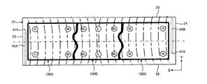
本発明の実施例1である電池モジュール(蓄電モジュールに相当する)について説明する。図1は、電池モジュールの上面図である。図2は、図1に示すY1−Y1断面図である。図1及び図2において、X軸、Y軸およびZ軸は、互いに直交する軸である。本実施例では、鉛直方向に延びる軸をZ軸としている。X軸、Y軸およびZ軸の関係は、他の図面においても同様である。
Example 1
A battery module (corresponding to a power storage module) that is
本実施例の電池モジュール1は、例えば、ハイブリッド自動車や電気自動車などの車両に搭載することができ、走行用モータに電力を供給する電源装置として使用される。
The
電池モジュール1は、複数の単電池(蓄電素子に相当する)10を有する。各単電池10は、Z方向に延びている。複数の単電池10は、X−Y平面内において並んでいる。例えば、X方向を第1の配列方向として複数の単電池10を並べ、かつY方向を第2の配列方向として、第1の配列方向に並べられた複数の単電池10を複数段並べて、電池モジュールを形成することができる。
The
なお、本実施例では、Y方向に配列される各単電池10は、X方向にずれている。これは、Y方向に多くの単電池10が配置されるように、又はY方向の電池モジュール1の長さを短くするためである。一方で、各単電池10をX方向にずらさないで、Y方向において一致するように配列することもできる。
In the present embodiment, the
単電池10は、いわゆる円筒型電池であり、X−Y平面における単電池10の断面が円形に形成されている。単電池10は、円筒状に形成された電池ケースの内部に発電要素が収容されている。単電池10としては、ニッケル水素電池やリチウムイオン電池といった二次電池を用いることができる。また、二次電池の代わりに、電気二重層キャパシタを用いることができる。
The
図2に示すように、単電池10の長手方向(Z方向)における両端には、正極端子11および負極端子12が設けられている。単電池10の外装である電池ケースは、ケース本体および蓋体によって構成することができる。円筒状に形成されたケース本体に発電要素が収容され、蓋体によってケース本体が塞がれることで単電池10が構成される。
As shown in FIG. 2, a
蓋およびケース本体の間には、絶縁材で形成されたガスケットが配置されている。蓋は、発電要素の正極板が電気的に接続されており、単電池10の正極端子11として用いられる。ケース本体は、発電要素の負極板が電気的に接続されており、単電池10の負極端子12として用いられる。本実施例では、Z方向において蓋(正極端子11)と対向するケース本体の端面を、負極端子12として用い、Z方向両端において正極端子11及び負極端子12が位置している。
A gasket formed of an insulating material is disposed between the lid and the case main body. The lid is electrically connected to the positive electrode plate of the power generation element, and is used as the
電池モジュール1を構成するすべての単電池10は、図2に示すように、正極端子11が上方に位置するように配置されている。すべての単電池10の正極端子11は、同一平面内(X−Y平面内)において並んで配置されている。負極端子12についても同様である。
As shown in FIG. 2, all the
各単電池10は、保持部材であるホルダ20によって保持される。ホルダ20は、X方向に長尺状に形成されており、各単電池10が挿入される複数の開口部21を有している。開口部21は、単電池10の外周面に沿った形状(具体的には、円形状)に形成されている。開口部21は、単電池10の数だけ設けられている。上述した複数の単電池10の配列位置に対応して、開口部21がX方向に複数並んでおり、かつX方向に並ぶ複数の開口部21の列が、Y方向に複数並んで配置されている。
Each
ホルダ20は、例えば、アルミニウムなどの熱伝導性に優れた金属材や熱伝導性に優れた樹脂材で形成することができる。なお、ホルダ20の開口部21および単電池10の間には、樹脂などの絶縁材によって形成された絶縁体を配置することができる。
The
モジュールケース30は、X−Y平面内において、ホルダ20によって保持される複数の単電池10を囲む形状に形成されており、モジュールケース30の内側に複数の単電池10が収容される。モジュールケース30は、単電池10の正極端子11側に位置する上面に、複数の開口部30aが形成されている。開口部30aは、単電池10の正極端子11側の端部が挿入される。モジュールケース30は、樹脂などの絶縁材で形成することができる。
The
なお、モジュールケース30のX方向に沿う側面には、通風口としてスリットを複数設けることができる(不図示)。スリットは、所定の間隔を空けてモジュールケース30の側面それぞれに形成することができる。例えば、冷却風を一側面側のスリットから流入させる。冷却風は、電池モジュール1内をY方向に流れ、他側面のスリットから電池モジュール1に流出させて単電池10を冷却することができる。
A plurality of slits (not shown) can be provided on the side surface of the
単電池10の負極端子12側の領域は、ホルダ20の開口部21によって、X−Y平面内で位置決めされ、単電池10の正極端子11側の領域は、モジュールケース30の開口部30aによって、X−Y平面で位置決めされる。単電池10の長手方向(Z方向)における両端が、ホルダ20及びモジュールケース30によってそれぞれ位置決めされており、X−Y平面内で隣り合う2つの単電池10が互いに接触してしまうことを防止している。
The region on the
本実施例の電池モジュール1は、図2に示すように、ホルダ20をベースに、単電池10の負極端子12側の端部が各開口部21に挿入され、各単電池10がホルダ20から上方に直立した状態で設けられる。そして、ホルダ20の開口部21から露出した単電池10の各負極端子12側には、バスバー14が設けられる。バスバー14は、Z方向において複数の単電池10(負極端子12)に対して所定距離離間して配置される。負極端子12は、Z方向に突出した接続部14aと接続される。
As shown in FIG. 2, the
また、モジュールケース30の開口部30aから上方に露出した単電池10の正極端子11側には、バスバー15が設けられる。バスバー15は、Z方向において複数の単電池10(正極端子11)に対して所定距離離間して配置される。正極端子11は、Z方向に突出した接続部15aと接続される。
A
電池モジュール1の上面には、バスバー15を上方から覆うカバー部材31が設けられている。カバー部材31は、X−Y平面に延び、単電池10の正極端子11が露出するモジュールケース30の上面全体を覆う形状に形成されている。カバー部材31は、例えば、モジュールケース30に固定することができる。カバー部材31は、モジュールケース30と同様に、樹脂等で形成することができる。
A
一方、電池モジュール1の下面には、バスバー14を覆うカバー部材32が設けられている。カバー部材32は、X−Y平面に延び、単電池10の負極端子12が露出するホルダ20の下面全体を覆う形状に形成されている。カバー部材32は、X−Y平面内に並ぶ複数の単電池10の負極端子12側を覆い、ガスの排出スペースSを形成するための金属製の部材である。カバー部材32は、例えば、ホルダ20に固定するための不図示の固定部を備えることができる。
On the other hand, a
本実施例の単電池10は、単電池10内部で発生するガスを外部に排出するための排出弁(不図示)を設けることができる。排出弁は、例えば、負極端子12を構成するケース本体の底部に設けることができる。排出弁は、例えば、破断弁であり、負極端子12を構成するケース本体の底部に形成される溝で構成することができる。ガスの発生によって高くなる単電池10の内圧に対して溝からケース本体の底部が破断することで、内部のガスを単電池10の外部に排出することができる。
The
電池モジュール1の下面において、バスバー14が配置される領域の周囲は、カバー部材32によって覆われ、ホルダ20の下面とカバー部材32とで密閉された排出スペースSが形成されている。カバー部材32には、排出スペースSの排出口32aを設けることができる。排出弁を介して単電池10内部から排出されたガスは、カバー部材32と接触しながら排出スペースSを流れ、排出口32aから電池モジュール1の外部に排出される。排出口32aには、車外と連通する排出ホースなどを接続することができる。
On the lower surface of the
図3は、本実施例のバスバーユニットの構成斜視図である。バスバー14は、金属といった、導電性を有する材料で形成されている。バスバー14は、単電池10の各負極端子12と接続される接続部14aを複数有している。接続部14aは、X−Y平面において単電池10(負極端子12)の数だけ設けられており、Z方向において負極端子12と対向する位置に設けられている。
FIG. 3 is a configuration perspective view of the bus bar unit of the present embodiment. The
バスバー14は、Z方向を厚み(板厚)方向とした平面状の板状部材をプレス打ち抜き加工することで形成することができる。単電池10(負極端子12)の配列位置に対応する各位置に、複数の接続部14aが所定間隔を空けて形成されている。板状部材(基端部14b)からZ方向に突出した接続部14aは、負極端子12に溶接接続される。負極バスバーであるバスバー14全体は、複数の各単電池10の負極の電荷を帯びている。
The
バスバー15も、金属などの導電性を有する材料で形成されている。接続部15aは、X−Y平面において単電池10(正極端子11)の数だけ設けられており、Z方向において正極端子11と対向する位置に設けられている。
The
バスバー15は、バスバー14と同様に、平面状の板状部材をプレス加工することにより形成することができる。接続部15aは、板状部材(基端部15b)から単電池10の正極端子11に向かって突出した形状に形成されている。X−Y平面において単電池10(正極端子11)の数だけ複数の接続部15aが所定間隔を空けて形成されている。接続部15aは、正極端子11に溶接接続される。正極バスバーであるバスバー15全体は、複数の各単電池10の正極の電荷を帯びている。
Similarly to the
本実施例の接続部15aは、所定値以上の電流が流れた際に溶断して単電池10(正極端子11)との電気的な接続を遮断するヒューズとして用いることができる。接続部15aは、例えば、バスバー14の接続部14aよりも幅が小さく形成され、溶断特性に対する上限電流値が低くなるように構成することができる。
The
本実施例の複数の単電池10は、正極端子11(又は負極端子12)の向きが、Z方向において同じ向きとなるように並んで配置されている。負極端子12それぞれに対して1つのバスバー14が接続され、単電池10の正極端子11それぞれに対して1つのバスバー15が接続することにより、複数の単電池10が電気的に並列に接続されている。なお、バスバー14,15の各接続部以外の領域は、絶縁フィルム等で覆うことができる。
The plurality of
そして、本実施例の電池モジュール1は、図2に示すように、所定数の各単電池10をバスバー14,15で並列に接続して1つの電池ブロックを構成し、各電池ブロック100A,100B,100Cが直列に接続されている。図2の例では、隣り合う電池ブロック100A,100B,100C間がリード部16,17を介して電気的に直列に接続される態様を、二点鎖線で模式的に示している。
As shown in FIG. 2, the
X方向に並んで配置される電池ブロック100Aのバスバー14のリード部16が、隣り合う電池ブロック100Bのバスバー15のリード部17と接続される。また、電池ブロック100Bのバスバー14のリード部16が、隣り合う電池ブロック100Cのバスバー15のリード部17と接続される。
図3に示すように、リード部16は、バスバー14の基端部14bの一部を延設して形成することができる。リード部17も、バスバー15の基端部15bの一部を延設して形成することができる。リード部16,17は、Z方向に延びる細長い板状に形成されており、X方向において略同じ位置に配置されている。リード部16,17は、互いに溶接接続される。なお、ホルダ20に挿入された各単電池10に対してバスバー14,15が取り付けられた状態において、リード部16は、ホルダ20のY方向端部26の外側に配置される。
As shown in FIG. 3, the
本実施例のバスバーユニットは、1つの電池ブロック内の複数の単電池10を並列に接続するための一対のバスバー14,15(第1バスバーに相当する)と、X方向に並ぶ複数の電池ブロック毎に設けられた一対のバスバー14,15において、隣り合う電池ブロックの一方のバスバー14と他方のバスバー15を接続するためのリード部16,17(第2バスバーに相当する)と、を含んで構成されている。
The bus bar unit of this embodiment includes a pair of
直列に接続された複数の電池ブロックの各終端は、電池モジュール1の電極端子として構成される。図2の例において、X方向の一端に位置する電池ブロック100Aのバスバー15の一部を延設することで、電池モジュール1の正極端子Pを取り出すことができる。また、X方向の他端に位置する電池ブロック100Cのバスバー14の一部を延設することで、電池モジュール1の負極端子Nを取り出すことができる。
Each terminal of the plurality of battery blocks connected in series is configured as an electrode terminal of the
電池モジュール1の正極端子P及び負極端子Nは、電池モジュール1のX方向端部両側にそれぞれ配置され、X方向においてモジュールケース30(カバー部材31)から外側に突出している。
The positive terminal P and the negative terminal N of the
なお、電池ブロック100Cのバスバー14は、電池モジュール1の下面側に配置されているので、例えば、図2及び図3に示すように、電池モジュール1の上面側まで延びる延設部18を設けるように構成することができる。また、正極端子P及び負極端子Nは、バスバー14,15の一部を延設せずに、各バスバー14,15と接続される別体の電極端子であってもよい。
Since the
本実施例の電池モジュール1は、ホルダ20に保持された複数の単電池10が複数の電池ブロック100A,100B,100Cに区分けされ、電池ブロック100A,100B,100C間が直列に接続されている。各電池ブロックに属する複数の各単電池10は、並列に接続されている。1つの電池ブロックは、X方向に一列に配置された5つの単電池10が、Y方向に4段並んで配置されており、電池ブロック単位あたりに含まれる単電池10の数は、同じ数となっている。なお、1つの電池ブロックに含まれる単電池10の数や各単電池10の配列方向は、適宜設定することができる。
In the
そして、本実施例では、電池モジュール1の温度調節手段として、一対のヒータ40A,40Bが設けられている。ヒータ40A,40Bは、ホルダ20を介して各単電池10を昇温させるための加熱手段であり、不図示の電力供給源から供給される電力によって駆動する。Y方向に沿って直線状に延びるヒータ40A,40Bは、図1に示すように、ホルダ20のX方向端部両側(23,24)にそれぞれ設けられ、ホルダ20に取り付けられる複数の単電池10全体をX方向から挟み込むように配置されている。
In this embodiment, a pair of heaters 40 </ b> A and 40 </ b> B are provided as temperature adjusting means for the
ホルダ20には、ヒータ40A,40Bが埋め込まれる挿通穴22A,22BがX方向端部にそれぞれ設けられている。挿通穴22A,22Bは、互いに異なるY方向一端側から他端側に向かって延びるようにホルダ20の内部に形成されている。
The
ここで、挿通穴22Aは、ホルダ20のY方向端部26からY方向端部25に向かって直線状に延びているとともに、ヒータ40Aの端部41Aが、Y方向において電池ブロック100Aのブロック長の略中央部位よりもY方向端部25側に位置するように形成されている。同様に、挿通穴22Bは、ホルダ20のY方向端部25からY方向端部26に向かって直線状に延びているとともに、ヒータ40Bの端部41Bが、Y方向において電池ブロック100Cのブロック長の略中央部位よりもY方向端部26側に位置するように形成されている。なお、ヒータ40A,40Bそれぞれは、Y方向における同じ一端部から他端部に向かって直線状に延びるように配置してもよい。
Here, the
なお、ヒータ40A,40Bは、ホルダ20に埋め込んだり、ホルダ20の外表面に張り付けるように設けたりすることができるが、ヒータ40A,40B及びホルダ20間の伝熱効率を向上させるために、本実施例では、ホルダ20の外表面ではなく、ホルダ20の内部にヒータ40A,40Bを埋め込んでいる。
The
ヒータ40A,40Bの電力供給源としては、例えば、車両に搭載される補機バッテリや、外部充電時に接続される商用電源などの外部電源がある。ヒータ40A,40Bの電力供給は、車両に搭載される不図示の制御ユニットによって制御することができる。制御ユニットは、ヒータ40A,40Bと電力供給源との間でスイッチを用いた電流経路のオン/オフ制御や、DC/DCコンバータなどを用いたヒータ40A,40Bへの電力供給制御を行うことができる。
Examples of the power supply source of the
本実施例のヒータ40A,40Bは、ホルダ20に取り付けられる。ホルダ20は、上述のように単電池10の一端側が開口部21に挿入され、複数の単電池10それぞれを保持している。ホルダ20は、各単電池10の散熱部材として機能するとともに、ヒータ40A,40Bからの熱を単電池10に伝える伝熱部材として機能する。本実施例では、ヒータ40A,40Bによってホルダ20が温められることで、ホルダ20から各単電池10に熱が伝えられ、単電池10が昇温される。
The heaters 40 </ b> A and 40 </ b> B of this embodiment are attached to the
単電池10は、電池温度が低いと内部抵抗が増加する。内部抵抗が増加すると、単電池10の入出力性能が低くなるので、ヒータ40A,40Bで単電池10を加熱することで、負荷への電力供給の際の電池出力性能を向上させたり、回生電力や外部充電の際の電池入力性能を向上させたりすることができる。
The
しかしながら、ヒータ40A,40Bの配置の仕方によっては、ホルダ20に保持される単電池10間に温度バラツキが生じてしまう。特に、ホルダ20に保持される複数の単電池10が複数の電池ブロックに区画され、電池ブロック毎に電池ブロック内の単電池10間を並列に接続し、かつ電池ブロック間を直列に接続する場合には、電池ブロックの分け方とヒータ40A,40Bの配置位置によっては、1つの電池ブロック内の単電池10間で温度バラツキが生じてしまう。
However, depending on how the heaters 40 </ b> A and 40 </ b> B are arranged, temperature variation occurs between the
並列接続される単電池10群において単電池10間で温度バラツキが生じると、例えば、温度が低い単電池10よりも温度の高い単電池10により多くの電流が流れる。特定の単電池10に多くの電流が流れることで、他の単電池10よりも電池温度がさらに上昇したり、電池劣化が促進されてしまうため、並列接続される単電池10群の各単電池10間での温度バラツキを抑制する必要がある。
In the group of
そこで、本実施例の電池モジュール1は、ヒータ40A,40Bを用い、複数の単電池10が取り付けられるホルダ20を介した単電池10の昇温構造において、ヒータ40A,40Bがホルダ20のX方向端部に、Y方向に沿って直線状に配置される。そして、複数の単電池10が、Y方向に沿って複数の電池ブロックに区画され、並列接続された複数の単電池10群で構成される各電池ブロックがX方向に並び、かつ互いに直列に接続されるように構成される。
Therefore, in the
ヒータ40A,40Bが、並列接続される単電池10群のY方向におけるブロック長に沿って直線状に延び、ホルダ20のX方向端部に配置されることで、ヒータ40A,40Bによる昇温に伴って形成される温度分布は、Y方向に沿った温度バラツキが抑制されつつ、ホルダ20のX方向において温度勾配(温度差)を持つように形成される。
The
ここで、複数の単電池10は、ヒータ40A,40Bが直線状に延びるY方向に沿って複数の電池ブロックに区画されている。このため、ホルダ20のX方向に温度差を有する温度分布が形成されても、並列接続される単電池10群間では温度差が大きくなるものの、並列接続される単電池10群のブロック単位では、X方向における温度勾配が低減されることになる。
Here, the plurality of
図4は、本実施例の電池モジュール1の加熱の様子を示す図である。図4の例において、一点鎖線は、ヒータ40A,40Bからホルダ20に伝達される熱の様子を示している。また、2点鎖線は、電池ブロックのY方向におけるブロック長の中央を示しており、後述する図5及び図6の例についても同様である。
FIG. 4 is a diagram illustrating a heating state of the
図4に示すように、ヒータ40A,40BがY方向に直線状に延びているため、Y方向に沿った温度バラツキが抑制され、Y方向に略平行な均一の温度分布が形成される。
As shown in FIG. 4, since the
ホルダ20のX方向において、ヒータ40Aからホルダ20の内部に向かうにつれて、温度が低くなる温度勾配が形成されるが、複数の単電池10がX方向において複数の電池ブロックに区画され、電池ブロック100A,100B,100CがX方向に並んでいる。
In the X direction of the
このため、電池ブロック単位でのX方向における温度勾配を小さくすることができる。例えば、図4において、H(High)、M(Medium)、ML(Medium-Low)、L(LOW)は、ヒータ40A,40Bからの熱伝達によってホルダ20を介して昇温された単電池10の温度度合いを示している。H(High)、M(Medium)、ML(Medium-Low)、L(LOW)の順に、温度度合いが低くなっている。
For this reason, the temperature gradient in the X direction in battery block units can be reduced. For example, in FIG. 4, H (High), M (Medium), ML (Medium-Low), and L (LOW) are
図4に示すように、ヒータ40Aに隣接する電池ブロック100Aは、ヒータ40A側の温度が高くなり(「H」)、ヒータ40Aから内部に向かって離れるにつれて、温度が低くなるが、Y方向に沿って区画された電池ブロック100A内では、ヒータ40Aから一番遠い側の温度が「M」となる。同様に、ヒータ40Bに隣接する電池ブロック100Cも、ヒータ40B側の温度が「H」と高くなり、ヒータ40Bから一番遠い側の温度が「M」となる。
As shown in FIG. 4, in the
そして、電池ブロック100BのX方向端部側は、ヒータ40A,40Bの熱の影響を受け、隣接する電池ブロック100A,100Cよりも低い温度(「ML」)となり、電池ブロック100BのX方向中央部位では、X方向においてヒータ40A,40Bそれぞれから一番遠い位置となるので、温度が「L」となり、X方向において一番低い温度となる。
The X-direction end portion side of the
このように、X方向において、電池ブロック100A,100Cの一端側と他端側との間の温度勾配は、「H」から「M」となり、電池ブロック100BのX方向一端側と他端側との間の温度勾配は、「ML」から「L」となる。
Thus, in the X direction, the temperature gradient between the one end side and the other end side of the battery blocks 100A, 100C is changed from “H” to “M”, and the one end side and the other end side of the
一方、図5及び図6は、ヒータによる電池モジュール1の加熱の様子を示す従来例1、従来例2を示す図である。まず、図5に示す従来例1では、ヒータ40A,40Bが、X方向に並ぶ電池ブロックの配列方向に対して略平行に設けられている。このとき、2つのヒータ40A,40Bは、Y方向端部25側のみに配置されている。なお、図5及び図6の例においても、一点鎖線は、ヒータ40A,40Bからホルダ20に伝達される熱の様子を示している。
5 and 6 are diagrams showing Conventional Example 1 and Conventional Example 2 showing how the
図5の紙面において、ヒータ40Aに一番近い電池ブロック100Aでは、ヒータ40Aから一番遠い右下の領域に温度が低い領域(「ML」)が形成され、左上の一番近い位置に温度が高い領域(「H」)が形成される。このとき、電池ブロック100A内での単電池10間の温度勾配(温度差)は、「H」から「ML」となり、図4の例に比べて温度勾配が大きくなる。電池ブロック100Cについても同様である。
In the paper surface of FIG. 5, in the
特に、電池ブロック100A,100C間に挟まれる電池ブロック100Bにおいては、ヒータ40A,40Bが配置されるY方向端部側の紙面上側の温度が高いものの、紙面下側の各ヒータ40A,40Bから一番遠い領域では、温度が低くなる。電池ブロック100B内での単電池10間の温度勾配(温度差)は、「M」から「L」となり、図4の例に比べて温度勾配が大きくなる。
In particular, in the
したがって、電池ブロック100A,100C内では、並列接続される単電池10間において太点線で示すような低温領域と高温領域とが発生してしまうとともに、電池ブロック100B内でも、太点線で示すような低温領域及び高温領域が発生してしまう。
Therefore, in the battery blocks 100A and 100C, a low temperature region and a high temperature region as indicated by a thick dotted line occur between the
また、図6に示す従来例2は、ヒータ40A,40Bが、X方向に並ぶ電池ブロック100,100B,100Cの配列方向に対して略平行に設けられている。このとき、2つのヒータ40A,40Bは、ホルダ20のX方向に沿って配置され、かつY方向端部25端側と端部26側にそれぞれ離間して配置されている。
In the second conventional example shown in FIG. 6, the
図6に示すように、ヒータ40Aに一番近い電池ブロック100Aでは、ヒータ40Aから一番遠い右上の領域に温度が低い領域が形成され、ヒータ40Aに一番近い左下の領域に温度が高い領域が形成されてしまう。電池ブロック100Bについても同様であり、ヒータ40Bから一番遠い左下の領域に温度が低い領域が形成され、ヒータ40Aに一番近い右上の領域に温度が高い領域が形成されてしまう。
As shown in FIG. 6, in the
このため、図6の例においても、電池ブロック100A,100C内での単電池10間の温度勾配(温度差)は、「H」から「ML」となり、図4の例に比べて温度勾配が大きくなる。また、電池ブロック100Bは、ヒータ40Aに一番近いY方向端部26側の紙面左下の領域の温度が高くなり、Y方向端部25側の紙面左上の各ヒータ40A,40Bから一番遠い領域では、温度が低くなる。同様に、ヒータ40Bに一番近いY方向端部25側の紙面右上の領域の温度が高くなり、Y方向端部26側の紙面右下の各ヒータ40A,40Bから一番遠い領域では、温度が低くなる。
Therefore, also in the example of FIG. 6, the temperature gradient (temperature difference) between the
したがって、従来例2においても、電池ブロック100A,100C内では、並列接続される単電池10間で太点線で示すような低温領域と高温領域とが発生してしまうとともに、電池ブロック100B内でも、太点線で示すような低温領域と高温領域とが発生してしまう。
Therefore, also in Conventional Example 2, in the battery blocks 100A and 100C, a low temperature region and a high temperature region as indicated by a thick dotted line are generated between the
このように本実施例の電池モジュール1は、ヒータ40A,40Bによる昇温の際に、Y方向に沿って区画されたブロック単位でX方向に並ぶ単電池10群毎の温度バラツキが抑制された昇温を行うことができる。これにより、並列接続される単電池10群において特定の単電池10に多くの電流が流れることを抑制することができる。
As described above, in the
また、ヒータ40A,40Bは、ホルダ20のX方向端部両側にそれぞれ設けられ、Y方向に沿って配置される一対のヒータ40,40Bが、複数の単電池10全体をX方向から挟み込むように配置されている。一対のヒータ40A,40Bが、ホルダ20のX方向両端から挟み込むように配置されることで、ヒータ40A,40Bによる熱が、ホルダ20のX方向両端から均等に内部に向かって順に伝達される。したがって、ホルダ20のX方向一端側のみにヒータを設ける場合に比べて、並列接続される単電池10群のブロック単位内でのX方向における温度勾配をより低減させることができる。
The
より具体的に説明すると、ホルダ20のX方向両端から均等に内部に向かって順に熱が伝達されることで、ホルダ20のX方向一端側から他端側に向かって低くなる一方向への温度勾配が形成されなくなり、X方向において一方のヒータ40Aから離れても、他方のヒータ40Bからの熱の影響を受けるようになるため、電池ブロック単位内でのX方向にける温度勾配が低減されることになる。
More specifically, the temperature in one direction becomes lower from one end side in the X direction toward the other end side of the
また、Y方向に直線状に延びるヒータ40A,40Bの各端部41A,41Bが、ホルダ20の一端(26,25)側から電池ブロックの略中央部位よりもホルダ20の他端(25,26)側に位置するように設けられているので、Y方向における温度バラツキが抑制された温度分布が形成され易くなる。なお、ヒータ40A,40Bは、ホルダ20の一端(26,25)側からホルダ20の他端(25,26)側まで延びるように構成してもよい。
Further, the
また、ホルダ20は、X方向に長尺状に形成されているが、ホルダの長尺方向において複数の単電池10がY方向に沿って複数に区画されているため、ヒータ40A,40Bによる昇温の際に、X方向及びY方向に並び、各単電池10間が並列に接続された単電池10群のブロック単位で、温度バラツキが抑制された昇温を行うことができる。特に、長尺状に形成されるホルダ20(電池モジュール1)において、一対のヒータ40A,40Bが、ホルダ20のX方向両端から挟み込むように配置されることで、並列接続される単電池10群のブロック単位内でのX方向における温度勾配をより低減させることができるとともに、X方向に並ぶ電池ブロック100A,100B,100C間での温度バラツキも低減させることができる。
In addition, the
次に、図7を参照して本実施例の変形例について説明する。図7は、電池モジュール1の加熱の様子を示す図である。本変形例は、ヒータ40Aがホルダ20のX方向一端側にのみに設けられ、他端側にヒータ40Bが設けられていない。なお、一点鎖線は、ヒータ40Aからホルダ20に伝達される熱の様子を示している。
Next, a modification of the present embodiment will be described with reference to FIG. FIG. 7 is a diagram illustrating a heating state of the
図7に示すように、ヒータ40AがY方向に直線状に延びているため、Y方向に沿った温度バラツキが抑制され、Y方向に略平行な均一の温度分布が形成される。このとき、ヒータ40Aが設けられるX方向端部23から他端側のX方向端部24に向かうにつれて、温度が低くなる温度勾配が形成される。
As shown in FIG. 7, since the
しかしながら、本実施例の電池モジュール1は、複数の単電池10がX方向において複数の電池ブロックに区画され、電池ブロック100A,100B,100CがX方向に並んでいるので、ヒータ40Aから遠ざかるにつれて温度が低くなり、電池ブロック100A,100B,100C間での温度バラツキが大きくなるものの、図4に示したように、電池ブロック単位でのX方向における温度勾配を小さくすることができる。
However, in the
このようにY方向に沿って直線状のヒータ40Aのみを配置しても、Y方向に沿って複数の単電池10が区画され、並列接続される単電池10群がX方向に並ぶように配置されているので、電池ブロック単位では、X方向における温度勾配が低減される。したがって、ヒータ40Aのみによる昇温の際に、Y方向に沿って区画された電池ブロック単位でX方向に並ぶ並列接続された単電池10群毎の温度バラツキが抑制された昇温を行うことができる。
Thus, even if only the
以上、本発明の実施例について説明したが、上記電池モジュール1において、並列接続される単電池10群を、3つではなく、4つ以上の単電池10群に区画することもできる。この場合、X方向に対して区画する数、言い換えれば、X方向に並び、互いに直列に接続される単電池10群の数が多ければ多いほど、電池ブロック単位当たりのX方向のブロック長が短くなるため、1つの電池ブロック内のX方向における温度バラツキをさらに低減させることができる。区画数に応じて図3に示したバスバーユニットを構成する一対のバスバー14,15の数を増やして構成することができる。
As mentioned above, although the Example of this invention was described, in the said
また、上記電池モジュール1は、ホルダ20をX方向に長尺状に形成しているが、Y方向に長尺状に形成したり、略正方形に形成したりしてもよい。このような場合であっても、Y方向に沿って直線状にヒータ40A,40Bを配置し、かつ、Y方向に沿って複数の単電池10が区画され、並列接続される単電池10群がX方向に並ぶように配置されていれば、Y方向に沿って区画された電池ブロック単位でX方向に並ぶ並列接続された単電池10群毎の温度バラツキが抑制された昇温を行うことができる。
In the
さらに、上記電池モジュール1において、例えば、ホルダ20を、電池モジュール1の下側ではなく、電池モジュール1の上側に設けることができる。この場合、上側に設けられるホルダ20に対応し、ホルダ20とホルダ20の上方に配置されるカバー部材32との間に排出スペースSが設けられるように構成することができる。ヒータ40A,40Bは、上述した実施例同様に、ホルダ20のX方向端部において、Y方向に直線状に設けることができる。
Further, in the
また、複数の単電池10は、負極端子12側のZ方向一端がホルダ20によって保持されているが、例えば、Z方向において単電池20の略中央部位が保持されるように、開口部21に各単電池10を挿入することができる。
Further, in the plurality of
1:電池モジュール、10:単電池、11:正極端子、12:負極端子、14:バスバー、15:バスバー、16,17:リード部、20:ホルダ、21:開口部、22A,22B:挿通穴、30:モジュールケース、31,32:カバー部材、40A,40B:ヒータ、100A,100B,100C:電池ブロック 1: battery module, 10: single battery, 11: positive terminal, 12: negative terminal, 14: bus bar, 15: bus bar, 16, 17: lead part, 20: holder, 21: opening, 22A, 22B: insertion hole , 30: module case, 31, 32: cover member, 40A, 40B: heater, 100A, 100B, 100C: battery block
Claims (5)
前記複数の蓄電素子それぞれが挿入される複数の開口部が、前記所定方向と直交する平面内に配置されたホルダと、
前記ホルダの前記平面における第1方向の端部に設けられ、前記平面において前記第1方向と直交する第2方向に沿って直線状に配置される、前記ホルダを介して前記蓄電素子を昇温させるためのヒータと、
前記第1方向において前記複数の蓄電素子を前記第2方向に沿って複数のブロックに区画し、前記ブロック毎に前記ブロック内に含まれる前記蓄電素子間を並列に接続するための第1バスバーと、前記第1方向に隣り合う前記ブロック間を直列に接続するための第2バスバーと、を備えるバスバーユニットと、
を有することを特徴とする蓄電モジュール。 A plurality of power storage elements extending in a predetermined direction;
A plurality of openings into which the plurality of power storage elements are inserted, a holder disposed in a plane orthogonal to the predetermined direction;
The temperature of the power storage element is increased via the holder provided at an end portion in the first direction on the plane of the holder and linearly arranged along a second direction orthogonal to the first direction on the plane. A heater for making
A first bus bar for partitioning the plurality of power storage elements in the first direction into a plurality of blocks along the second direction, and connecting the power storage elements included in the block in parallel for each block; A bus bar unit comprising: a second bus bar for connecting in series between the blocks adjacent in the first direction;
A power storage module comprising:
前記開口部は、前記第1方向に複数配置され、かつ前記第1方向に並ぶ複数の前記開口部の列が、前記第2方向に複数配置されていることを特徴とする請求項1から4のいずれか1つに記載の蓄電モジュール。
The holder is formed in an elongated shape in the first direction,
The plurality of openings are arranged in the first direction, and a plurality of rows of the openings arranged in the first direction are arranged in the second direction. The electrical storage module as described in any one of these.
Priority Applications (3)
| Application Number | Priority Date | Filing Date | Title |
|---|---|---|---|
| JP2014214697A JP6070672B2 (en) | 2014-10-21 | 2014-10-21 | Power storage module |
| KR1020150143965A KR101718862B1 (en) | 2014-10-21 | 2015-10-15 | Power storage module |
| US14/886,588 US20160111760A1 (en) | 2014-10-21 | 2015-10-19 | Power storage module |
Applications Claiming Priority (1)
| Application Number | Priority Date | Filing Date | Title |
|---|---|---|---|
| JP2014214697A JP6070672B2 (en) | 2014-10-21 | 2014-10-21 | Power storage module |
Publications (2)
| Publication Number | Publication Date |
|---|---|
| JP2016081836A JP2016081836A (en) | 2016-05-16 |
| JP6070672B2 true JP6070672B2 (en) | 2017-02-01 |
Family
ID=55749780
Family Applications (1)
| Application Number | Title | Priority Date | Filing Date |
|---|---|---|---|
| JP2014214697A Active JP6070672B2 (en) | 2014-10-21 | 2014-10-21 | Power storage module |
Country Status (3)
| Country | Link |
|---|---|
| US (1) | US20160111760A1 (en) |
| JP (1) | JP6070672B2 (en) |
| KR (1) | KR101718862B1 (en) |
Families Citing this family (9)
| Publication number | Priority date | Publication date | Assignee | Title |
|---|---|---|---|---|
| US10700335B2 (en) * | 2016-09-07 | 2020-06-30 | Thunder Power New Energy Vehicle Development Company Limited | Battery system housing with internal busbar |
| US10396410B2 (en) | 2016-09-07 | 2019-08-27 | Thunder Power New Energy Vehicle Development Company Limited | Battery system housing with internal busbar |
| CN107068954A (en) * | 2017-01-11 | 2017-08-18 | 深圳市沃特玛电池有限公司 | A kind of battery module structure |
| KR102249509B1 (en) | 2017-09-20 | 2021-05-06 | 주식회사 엘지화학 | Battery Module Having Guide Coupling Structure and Battery Pack Having The Same |
| JP7078892B2 (en) * | 2018-03-14 | 2022-06-01 | トヨタ自動車株式会社 | Power storage device |
| JP7199817B2 (en) * | 2018-03-16 | 2023-01-06 | 矢崎総業株式会社 | battery pack |
| JP6982586B2 (en) * | 2019-02-27 | 2021-12-17 | 三菱パワー株式会社 | Fuel cell cartridges, fuel cell modules and combined cycle systems |
| JP7413212B2 (en) * | 2020-09-03 | 2024-01-15 | 愛三工業株式会社 | battery module |
| KR102687234B1 (en) * | 2021-10-12 | 2024-07-19 | 엘지전자 주식회사 | Energy Storage System |
Family Cites Families (14)
| Publication number | Priority date | Publication date | Assignee | Title |
|---|---|---|---|---|
| JP4902164B2 (en) * | 2005-09-28 | 2012-03-21 | 三洋電機株式会社 | Power supply |
| JP5004534B2 (en) * | 2006-08-21 | 2012-08-22 | 三洋電機株式会社 | Pack battery |
| JP2010503976A (en) * | 2006-09-18 | 2010-02-04 | マグナ・シユタイル・フアールツオイクテヒニク・アクチエンゲゼルシヤフト・ウント・コンパニー・コマンデイトゲゼルシヤフト | Modular battery device |
| JP5261043B2 (en) * | 2008-06-27 | 2013-08-14 | 三洋電機株式会社 | Battery pack for vehicles |
| US8815429B2 (en) * | 2009-01-12 | 2014-08-26 | A123 Systems Llc | Busbar supports and methods of their use for battery systems |
| KR101903492B1 (en) * | 2010-08-12 | 2018-10-02 | 후루카와 덴끼고교 가부시키가이샤 | Battery temperature regulation system and battery temperature regulation unit |
| US20120114996A1 (en) * | 2010-11-04 | 2012-05-10 | San-Chuan Yu | Battery holder, battery array using same |
| JP5736859B2 (en) * | 2011-03-11 | 2015-06-17 | 日産自動車株式会社 | Battery pack heater module connection structure |
| WO2012147137A1 (en) * | 2011-04-28 | 2012-11-01 | トヨタ自動車株式会社 | Battery pack |
| JP5790767B2 (en) * | 2011-09-21 | 2015-10-07 | トヨタ自動車株式会社 | VEHICLE BATTERY CONTROL DEVICE AND VEHICLE BATTERY CONTROL METHOD |
| KR101899481B1 (en) * | 2011-12-23 | 2018-09-18 | 삼성전자주식회사 | Method of forming line in electric device |
| JP2013134828A (en) * | 2011-12-26 | 2013-07-08 | Panasonic Corp | Battery module |
| JP5692132B2 (en) * | 2012-03-21 | 2015-04-01 | トヨタ自動車株式会社 | Power storage device |
| KR101720636B1 (en) * | 2012-11-30 | 2017-03-28 | 도요타 지도샤(주) | Electric storage apparatus |
-
2014
- 2014-10-21 JP JP2014214697A patent/JP6070672B2/en active Active
-
2015
- 2015-10-15 KR KR1020150143965A patent/KR101718862B1/en active IP Right Grant
- 2015-10-19 US US14/886,588 patent/US20160111760A1/en not_active Abandoned
Also Published As
| Publication number | Publication date |
|---|---|
| KR20160046731A (en) | 2016-04-29 |
| US20160111760A1 (en) | 2016-04-21 |
| JP2016081836A (en) | 2016-05-16 |
| KR101718862B1 (en) | 2017-03-22 |
Similar Documents
| Publication | Publication Date | Title |
|---|---|---|
| JP6070672B2 (en) | Power storage module | |
| EP3182483B1 (en) | Battery pack | |
| EP3131161B1 (en) | Current distribution system for a battery assembly utilizing non-overlapping bus bars | |
| JP4415570B2 (en) | Battery | |
| KR102230882B1 (en) | Cooling units for energy storage devices | |
| JP4641737B2 (en) | Pack battery | |
| US20170025657A1 (en) | Energy storage unit, particularly a battery module, and an energy storage system comprising a plurality of energy storage unit | |
| KR101282519B1 (en) | Battery module | |
| KR101597021B1 (en) | Temperature control device | |
| US10396410B2 (en) | Battery system housing with internal busbar | |
| US20140220396A1 (en) | Battery pack | |
| KR102388127B1 (en) | Top cover, battery module using the same, and battery pack and vehicle including the same | |
| EP3293794B1 (en) | Methods and systems for busbar cooling | |
| EP2631986B1 (en) | Battery module | |
| JP2014135180A (en) | Battery module | |
| JP2013038054A (en) | Battery module for high-voltage battery pack | |
| JP2018530857A (en) | Heating panel | |
| CN110612615B (en) | Battery unit, battery module containing same and application thereof | |
| KR101309153B1 (en) | Battery module | |
| KR102455141B1 (en) | Electrode Assembly Manufacturing Method for Battery Cell of Secondary Battery | |
| JP5692132B2 (en) | Power storage device | |
| JP2016091604A (en) | Battery pack for vehicle | |
| JP2015103383A (en) | Battery pack | |
| KR20180110937A (en) | Lithium secondary battery module, lithium secondary battery pack comprising the same, and control method of lithium ion battery | |
| US10079412B2 (en) | Electrochemical electricity storage cell |
Legal Events
| Date | Code | Title | Description |
|---|---|---|---|
| A621 | Written request for application examination |
Free format text: JAPANESE INTERMEDIATE CODE: A621 Effective date: 20160211 |
|
| A977 | Report on retrieval |
Free format text: JAPANESE INTERMEDIATE CODE: A971007 Effective date: 20161130 |
|
| TRDD | Decision of grant or rejection written | ||
| A01 | Written decision to grant a patent or to grant a registration (utility model) |
Free format text: JAPANESE INTERMEDIATE CODE: A01 Effective date: 20161206 |
|
| A61 | First payment of annual fees (during grant procedure) |
Free format text: JAPANESE INTERMEDIATE CODE: A61 Effective date: 20161219 |
|
| R151 | Written notification of patent or utility model registration |
Ref document number: 6070672 Country of ref document: JP Free format text: JAPANESE INTERMEDIATE CODE: R151 |