EP3073471B1 - Elastisches etikett und herstellungsverfahren dafür - Google Patents
Elastisches etikett und herstellungsverfahren dafür Download PDFInfo
- Publication number
- EP3073471B1 EP3073471B1 EP14864040.2A EP14864040A EP3073471B1 EP 3073471 B1 EP3073471 B1 EP 3073471B1 EP 14864040 A EP14864040 A EP 14864040A EP 3073471 B1 EP3073471 B1 EP 3073471B1
- Authority
- EP
- European Patent Office
- Prior art keywords
- layer
- stretch
- layers
- label
- film
- Prior art date
- Legal status (The legal status is an assumption and is not a legal conclusion. Google has not performed a legal analysis and makes no representation as to the accuracy of the status listed.)
- Active
Links
- 238000004519 manufacturing process Methods 0.000 title claims description 13
- 238000002372 labelling Methods 0.000 title description 2
- 239000010410 layer Substances 0.000 claims description 801
- 239000000463 material Substances 0.000 claims description 213
- 229920006302 stretch film Polymers 0.000 claims description 180
- 239000002344 surface layer Substances 0.000 claims description 108
- 229920013716 polyethylene resin Polymers 0.000 claims description 92
- 238000000034 method Methods 0.000 claims description 49
- 239000004711 α-olefin Substances 0.000 claims description 26
- 229920000092 linear low density polyethylene Polymers 0.000 claims description 23
- 229920000089 Cyclic olefin copolymer Polymers 0.000 claims description 14
- 238000002844 melting Methods 0.000 claims 1
- 230000008018 melting Effects 0.000 claims 1
- 238000005259 measurement Methods 0.000 description 42
- 229920005989 resin Polymers 0.000 description 33
- 239000011347 resin Substances 0.000 description 33
- 238000007639 printing Methods 0.000 description 27
- 239000011253 protective coating Substances 0.000 description 25
- -1 2-ethylhexyl Chemical group 0.000 description 24
- VGGSQFUCUMXWEO-UHFFFAOYSA-N Ethene Chemical compound C=C VGGSQFUCUMXWEO-UHFFFAOYSA-N 0.000 description 21
- 239000005977 Ethylene Substances 0.000 description 20
- 229920000573 polyethylene Polymers 0.000 description 20
- 239000011241 protective layer Substances 0.000 description 20
- 238000012360 testing method Methods 0.000 description 20
- 230000000052 comparative effect Effects 0.000 description 19
- 239000000049 pigment Substances 0.000 description 18
- 239000011230 binding agent Substances 0.000 description 14
- 239000000178 monomer Substances 0.000 description 14
- 238000004040 coloring Methods 0.000 description 13
- 239000000976 ink Substances 0.000 description 11
- 238000003475 lamination Methods 0.000 description 11
- 239000002904 solvent Substances 0.000 description 11
- NIXOWILDQLNWCW-UHFFFAOYSA-M Acrylate Chemical compound [O-]C(=O)C=C NIXOWILDQLNWCW-UHFFFAOYSA-M 0.000 description 10
- 238000002360 preparation method Methods 0.000 description 10
- 239000000654 additive Substances 0.000 description 9
- 239000004707 linear low-density polyethylene Substances 0.000 description 9
- 239000002609 medium Substances 0.000 description 9
- 230000000694 effects Effects 0.000 description 8
- 239000000314 lubricant Substances 0.000 description 8
- 229920005672 polyolefin resin Polymers 0.000 description 8
- 230000002411 adverse Effects 0.000 description 7
- 230000015572 biosynthetic process Effects 0.000 description 7
- 238000011156 evaluation Methods 0.000 description 7
- 238000002156 mixing Methods 0.000 description 7
- 229920001200 poly(ethylene-vinyl acetate) Polymers 0.000 description 7
- 229920001684 low density polyethylene Polymers 0.000 description 6
- 239000012968 metallocene catalyst Substances 0.000 description 6
- 239000000203 mixture Substances 0.000 description 6
- 238000007789 sealing Methods 0.000 description 6
- 239000002356 single layer Substances 0.000 description 6
- 229910021536 Zeolite Inorganic materials 0.000 description 5
- 239000011247 coating layer Substances 0.000 description 5
- HNPSIPDUKPIQMN-UHFFFAOYSA-N dioxosilane;oxo(oxoalumanyloxy)alumane Chemical compound O=[Si]=O.O=[Al]O[Al]=O HNPSIPDUKPIQMN-UHFFFAOYSA-N 0.000 description 5
- 238000001125 extrusion Methods 0.000 description 5
- 238000007646 gravure printing Methods 0.000 description 5
- 229920000642 polymer Polymers 0.000 description 5
- 239000010457 zeolite Substances 0.000 description 5
- LYCAIKOWRPUZTN-UHFFFAOYSA-N Ethylene glycol Chemical compound OCCO LYCAIKOWRPUZTN-UHFFFAOYSA-N 0.000 description 4
- 239000004698 Polyethylene Substances 0.000 description 4
- GWEVSGVZZGPLCZ-UHFFFAOYSA-N Titan oxide Chemical compound O=[Ti]=O GWEVSGVZZGPLCZ-UHFFFAOYSA-N 0.000 description 4
- 238000005266 casting Methods 0.000 description 4
- 239000008199 coating composition Substances 0.000 description 4
- 238000013461 design Methods 0.000 description 4
- 229920001519 homopolymer Polymers 0.000 description 4
- 238000006116 polymerization reaction Methods 0.000 description 4
- 238000004381 surface treatment Methods 0.000 description 4
- JRZJOMJEPLMPRA-UHFFFAOYSA-N 1-nonene Chemical compound CCCCCCCC=C JRZJOMJEPLMPRA-UHFFFAOYSA-N 0.000 description 3
- ZWEHNKRNPOVVGH-UHFFFAOYSA-N 2-Butanone Chemical compound CCC(C)=O ZWEHNKRNPOVVGH-UHFFFAOYSA-N 0.000 description 3
- LFQSCWFLJHTTHZ-UHFFFAOYSA-N Ethanol Chemical compound CCO LFQSCWFLJHTTHZ-UHFFFAOYSA-N 0.000 description 3
- XEKOWRVHYACXOJ-UHFFFAOYSA-N Ethyl acetate Chemical compound CCOC(C)=O XEKOWRVHYACXOJ-UHFFFAOYSA-N 0.000 description 3
- KFZMGEQAYNKOFK-UHFFFAOYSA-N Isopropanol Chemical compound CC(C)O KFZMGEQAYNKOFK-UHFFFAOYSA-N 0.000 description 3
- OKKJLVBELUTLKV-UHFFFAOYSA-N Methanol Chemical compound OC OKKJLVBELUTLKV-UHFFFAOYSA-N 0.000 description 3
- DNIAPMSPPWPWGF-UHFFFAOYSA-N Propylene glycol Chemical compound CC(O)CO DNIAPMSPPWPWGF-UHFFFAOYSA-N 0.000 description 3
- VYPSYNLAJGMNEJ-UHFFFAOYSA-N Silicium dioxide Chemical compound O=[Si]=O VYPSYNLAJGMNEJ-UHFFFAOYSA-N 0.000 description 3
- YXFVVABEGXRONW-UHFFFAOYSA-N Toluene Chemical compound CC1=CC=CC=C1 YXFVVABEGXRONW-UHFFFAOYSA-N 0.000 description 3
- 239000000853 adhesive Substances 0.000 description 3
- 230000001070 adhesive effect Effects 0.000 description 3
- 239000012790 adhesive layer Substances 0.000 description 3
- 235000013361 beverage Nutrition 0.000 description 3
- 239000003795 chemical substances by application Substances 0.000 description 3
- 229920001577 copolymer Polymers 0.000 description 3
- 238000001035 drying Methods 0.000 description 3
- 230000000670 limiting effect Effects 0.000 description 3
- VLKZOEOYAKHREP-UHFFFAOYSA-N n-Hexane Chemical compound CCCCCC VLKZOEOYAKHREP-UHFFFAOYSA-N 0.000 description 3
- 229920003023 plastic Polymers 0.000 description 3
- 239000004033 plastic Substances 0.000 description 3
- 239000002987 primer (paints) Substances 0.000 description 3
- 238000009864 tensile test Methods 0.000 description 3
- VXNZUUAINFGPBY-UHFFFAOYSA-N 1-Butene Chemical compound CCC=C VXNZUUAINFGPBY-UHFFFAOYSA-N 0.000 description 2
- ZGEGCLOFRBLKSE-UHFFFAOYSA-N 1-Heptene Chemical compound CCCCCC=C ZGEGCLOFRBLKSE-UHFFFAOYSA-N 0.000 description 2
- AFFLGGQVNFXPEV-UHFFFAOYSA-N 1-decene Chemical compound CCCCCCCCC=C AFFLGGQVNFXPEV-UHFFFAOYSA-N 0.000 description 2
- LIKMAJRDDDTEIG-UHFFFAOYSA-N 1-hexene Chemical compound CCCCC=C LIKMAJRDDDTEIG-UHFFFAOYSA-N 0.000 description 2
- KWKAKUADMBZCLK-UHFFFAOYSA-N 1-octene Chemical compound CCCCCCC=C KWKAKUADMBZCLK-UHFFFAOYSA-N 0.000 description 2
- WSSSPWUEQFSQQG-UHFFFAOYSA-N 4-methyl-1-pentene Chemical compound CC(C)CC=C WSSSPWUEQFSQQG-UHFFFAOYSA-N 0.000 description 2
- VTYYLEPIZMXCLO-UHFFFAOYSA-L Calcium carbonate Chemical compound [Ca+2].[O-]C([O-])=O VTYYLEPIZMXCLO-UHFFFAOYSA-L 0.000 description 2
- 239000004606 Fillers/Extenders Substances 0.000 description 2
- VZCYOOQTPOCHFL-OWOJBTEDSA-N Fumaric acid Chemical compound OC(=O)\C=C\C(O)=O VZCYOOQTPOCHFL-OWOJBTEDSA-N 0.000 description 2
- LRHPLDYGYMQRHN-UHFFFAOYSA-N N-Butanol Chemical compound CCCCO LRHPLDYGYMQRHN-UHFFFAOYSA-N 0.000 description 2
- 239000006096 absorbing agent Substances 0.000 description 2
- 239000003963 antioxidant agent Substances 0.000 description 2
- 239000002216 antistatic agent Substances 0.000 description 2
- TZCXTZWJZNENPQ-UHFFFAOYSA-L barium sulfate Chemical compound [Ba+2].[O-]S([O-])(=O)=O TZCXTZWJZNENPQ-UHFFFAOYSA-L 0.000 description 2
- 239000011324 bead Substances 0.000 description 2
- 235000014171 carbonated beverage Nutrition 0.000 description 2
- 239000011248 coating agent Substances 0.000 description 2
- 238000000576 coating method Methods 0.000 description 2
- 239000003086 colorant Substances 0.000 description 2
- 238000001816 cooling Methods 0.000 description 2
- 238000003851 corona treatment Methods 0.000 description 2
- 238000005520 cutting process Methods 0.000 description 2
- 235000019439 ethyl acetate Nutrition 0.000 description 2
- 229920006242 ethylene acrylic acid copolymer Polymers 0.000 description 2
- 229920001038 ethylene copolymer Polymers 0.000 description 2
- 229920005648 ethylene methacrylic acid copolymer Polymers 0.000 description 2
- 239000005038 ethylene vinyl acetate Substances 0.000 description 2
- 229920006244 ethylene-ethyl acrylate Polymers 0.000 description 2
- 229920005680 ethylene-methyl methacrylate copolymer Polymers 0.000 description 2
- 239000000945 filler Substances 0.000 description 2
- 239000003063 flame retardant Substances 0.000 description 2
- UAEPNZWRGJTJPN-UHFFFAOYSA-N methylcyclohexane Chemical compound CC1CCCCC1 UAEPNZWRGJTJPN-UHFFFAOYSA-N 0.000 description 2
- 239000012768 molten material Substances 0.000 description 2
- TVMXDCGIABBOFY-UHFFFAOYSA-N n-Octanol Natural products CCCCCCCC TVMXDCGIABBOFY-UHFFFAOYSA-N 0.000 description 2
- YWAKXRMUMFPDSH-UHFFFAOYSA-N pentene Chemical compound CCCC=C YWAKXRMUMFPDSH-UHFFFAOYSA-N 0.000 description 2
- QQONPFPTGQHPMA-UHFFFAOYSA-N propylene Natural products CC=C QQONPFPTGQHPMA-UHFFFAOYSA-N 0.000 description 2
- 125000004805 propylene group Chemical group [H]C([H])([H])C([H])([*:1])C([H])([H])[*:2] 0.000 description 2
- 239000000126 substance Substances 0.000 description 2
- 239000003017 thermal stabilizer Substances 0.000 description 2
- 239000004408 titanium dioxide Substances 0.000 description 2
- VZCYOOQTPOCHFL-UHFFFAOYSA-N trans-butenedioic acid Natural products OC(=O)C=CC(O)=O VZCYOOQTPOCHFL-UHFFFAOYSA-N 0.000 description 2
- KMOUUZVZFBCRAM-OLQVQODUSA-N (3as,7ar)-3a,4,7,7a-tetrahydro-2-benzofuran-1,3-dione Chemical compound C1C=CC[C@@H]2C(=O)OC(=O)[C@@H]21 KMOUUZVZFBCRAM-OLQVQODUSA-N 0.000 description 1
- RWNUSVWFHDHRCJ-UHFFFAOYSA-N 1-butoxypropan-2-ol Chemical compound CCCCOCC(C)O RWNUSVWFHDHRCJ-UHFFFAOYSA-N 0.000 description 1
- ARXJGSRGQADJSQ-UHFFFAOYSA-N 1-methoxypropan-2-ol Chemical compound COCC(C)O ARXJGSRGQADJSQ-UHFFFAOYSA-N 0.000 description 1
- JAHNSTQSQJOJLO-UHFFFAOYSA-N 2-(3-fluorophenyl)-1h-imidazole Chemical compound FC1=CC=CC(C=2NC=CN=2)=C1 JAHNSTQSQJOJLO-UHFFFAOYSA-N 0.000 description 1
- 125000000954 2-hydroxyethyl group Chemical group [H]C([*])([H])C([H])([H])O[H] 0.000 description 1
- YEYKMVJDLWJFOA-UHFFFAOYSA-N 2-propoxyethanol Chemical compound CCCOCCO YEYKMVJDLWJFOA-UHFFFAOYSA-N 0.000 description 1
- QOXOZONBQWIKDA-UHFFFAOYSA-N 3-hydroxypropyl Chemical group [CH2]CCO QOXOZONBQWIKDA-UHFFFAOYSA-N 0.000 description 1
- AYKYXWQEBUNJCN-UHFFFAOYSA-N 3-methylfuran-2,5-dione Chemical compound CC1=CC(=O)OC1=O AYKYXWQEBUNJCN-UHFFFAOYSA-N 0.000 description 1
- KNDQHSIWLOJIGP-UHFFFAOYSA-N 826-62-0 Chemical compound C1C2C3C(=O)OC(=O)C3C1C=C2 KNDQHSIWLOJIGP-UHFFFAOYSA-N 0.000 description 1
- HRPVXLWXLXDGHG-UHFFFAOYSA-N Acrylamide Chemical compound NC(=O)C=C HRPVXLWXLXDGHG-UHFFFAOYSA-N 0.000 description 1
- 229920000178 Acrylic resin Polymers 0.000 description 1
- 239000004925 Acrylic resin Substances 0.000 description 1
- DKPFZGUDAPQIHT-UHFFFAOYSA-N Butyl acetate Natural products CCCCOC(C)=O DKPFZGUDAPQIHT-UHFFFAOYSA-N 0.000 description 1
- XDTMQSROBMDMFD-UHFFFAOYSA-N Cyclohexane Chemical compound C1CCCCC1 XDTMQSROBMDMFD-UHFFFAOYSA-N 0.000 description 1
- IEPRKVQEAMIZSS-UHFFFAOYSA-N Di-Et ester-Fumaric acid Natural products CCOC(=O)C=CC(=O)OCC IEPRKVQEAMIZSS-UHFFFAOYSA-N 0.000 description 1
- IEPRKVQEAMIZSS-WAYWQWQTSA-N Diethyl maleate Chemical compound CCOC(=O)\C=C/C(=O)OCC IEPRKVQEAMIZSS-WAYWQWQTSA-N 0.000 description 1
- 239000004278 EU approved seasoning Substances 0.000 description 1
- XLYMOEINVGRTEX-ARJAWSKDSA-N Ethyl hydrogen fumarate Chemical compound CCOC(=O)\C=C/C(O)=O XLYMOEINVGRTEX-ARJAWSKDSA-N 0.000 description 1
- DGAQECJNVWCQMB-PUAWFVPOSA-M Ilexoside XXIX Chemical compound C[C@@H]1CC[C@@]2(CC[C@@]3(C(=CC[C@H]4[C@]3(CC[C@@H]5[C@@]4(CC[C@@H](C5(C)C)OS(=O)(=O)[O-])C)C)[C@@H]2[C@]1(C)O)C)C(=O)O[C@H]6[C@@H]([C@H]([C@@H]([C@H](O6)CO)O)O)O.[Na+] DGAQECJNVWCQMB-PUAWFVPOSA-M 0.000 description 1
- PEEHTFAAVSWFBL-UHFFFAOYSA-N Maleimide Chemical compound O=C1NC(=O)C=C1 PEEHTFAAVSWFBL-UHFFFAOYSA-N 0.000 description 1
- CERQOIWHTDAKMF-UHFFFAOYSA-N Methacrylic acid Chemical compound CC(=C)C(O)=O CERQOIWHTDAKMF-UHFFFAOYSA-N 0.000 description 1
- NTIZESTWPVYFNL-UHFFFAOYSA-N Methyl isobutyl ketone Chemical compound CC(C)CC(C)=O NTIZESTWPVYFNL-UHFFFAOYSA-N 0.000 description 1
- UIHCLUNTQKBZGK-UHFFFAOYSA-N Methyl isobutyl ketone Natural products CCC(C)C(C)=O UIHCLUNTQKBZGK-UHFFFAOYSA-N 0.000 description 1
- 239000000020 Nitrocellulose Substances 0.000 description 1
- 229920003355 Novatec® Polymers 0.000 description 1
- 239000004743 Polypropylene Substances 0.000 description 1
- 239000004820 Pressure-sensitive adhesive Substances 0.000 description 1
- OFOBLEOULBTSOW-UHFFFAOYSA-N Propanedioic acid Natural products OC(=O)CC(O)=O OFOBLEOULBTSOW-UHFFFAOYSA-N 0.000 description 1
- XTXRWKRVRITETP-UHFFFAOYSA-N Vinyl acetate Chemical compound CC(=O)OC=C XTXRWKRVRITETP-UHFFFAOYSA-N 0.000 description 1
- BZHJMEDXRYGGRV-UHFFFAOYSA-N Vinyl chloride Chemical compound ClC=C BZHJMEDXRYGGRV-UHFFFAOYSA-N 0.000 description 1
- 229920002433 Vinyl chloride-vinyl acetate copolymer Polymers 0.000 description 1
- HCHKCACWOHOZIP-UHFFFAOYSA-N Zinc Chemical compound [Zn] HCHKCACWOHOZIP-UHFFFAOYSA-N 0.000 description 1
- NIXOWILDQLNWCW-UHFFFAOYSA-N acrylic acid group Chemical group C(C=C)(=O)O NIXOWILDQLNWCW-UHFFFAOYSA-N 0.000 description 1
- 239000000443 aerosol Substances 0.000 description 1
- 235000013334 alcoholic beverage Nutrition 0.000 description 1
- 150000001298 alcohols Chemical class 0.000 description 1
- 150000001338 aliphatic hydrocarbons Chemical class 0.000 description 1
- 150000001336 alkenes Chemical class 0.000 description 1
- 229910052782 aluminium Inorganic materials 0.000 description 1
- XAGFODPZIPBFFR-UHFFFAOYSA-N aluminium Chemical compound [Al] XAGFODPZIPBFFR-UHFFFAOYSA-N 0.000 description 1
- PNEYBMLMFCGWSK-UHFFFAOYSA-N aluminium oxide Inorganic materials [O-2].[O-2].[O-2].[Al+3].[Al+3] PNEYBMLMFCGWSK-UHFFFAOYSA-N 0.000 description 1
- 150000001408 amides Chemical class 0.000 description 1
- 239000002518 antifoaming agent Substances 0.000 description 1
- 150000004945 aromatic hydrocarbons Chemical class 0.000 description 1
- 230000000712 assembly Effects 0.000 description 1
- 238000000429 assembly Methods 0.000 description 1
- NIDNOXCRFUCAKQ-UHFFFAOYSA-N bicyclo[2.2.1]hept-5-ene-2,3-dicarboxylic acid Chemical compound C1C2C=CC1C(C(=O)O)C2C(O)=O NIDNOXCRFUCAKQ-UHFFFAOYSA-N 0.000 description 1
- 125000000484 butyl group Chemical group [H]C([*])([H])C([H])([H])C([H])([H])C([H])([H])[H] 0.000 description 1
- 229910000019 calcium carbonate Inorganic materials 0.000 description 1
- 239000006229 carbon black Substances 0.000 description 1
- 150000001244 carboxylic acid anhydrides Chemical class 0.000 description 1
- 150000001733 carboxylic acid esters Chemical class 0.000 description 1
- 150000001734 carboxylic acid salts Chemical class 0.000 description 1
- 150000001735 carboxylic acids Chemical class 0.000 description 1
- 239000012461 cellulose resin Substances 0.000 description 1
- HNEGQIOMVPPMNR-IHWYPQMZSA-N citraconic acid Chemical compound OC(=O)C(/C)=C\C(O)=O HNEGQIOMVPPMNR-IHWYPQMZSA-N 0.000 description 1
- 229940018557 citraconic acid Drugs 0.000 description 1
- 230000008602 contraction Effects 0.000 description 1
- VVOLVFOSOPJKED-UHFFFAOYSA-N copper phthalocyanine Chemical compound [Cu].N=1C2=NC(C3=CC=CC=C33)=NC3=NC(C3=CC=CC=C33)=NC3=NC(C3=CC=CC=C33)=NC3=NC=1C1=CC=CC=C12 VVOLVFOSOPJKED-UHFFFAOYSA-N 0.000 description 1
- LDHQCZJRKDOVOX-NSCUHMNNSA-N crotonic acid Chemical compound C\C=C\C(O)=O LDHQCZJRKDOVOX-NSCUHMNNSA-N 0.000 description 1
- 238000005034 decoration Methods 0.000 description 1
- 239000003599 detergent Substances 0.000 description 1
- MTHSVFCYNBDYFN-UHFFFAOYSA-N diethylene glycol Chemical class OCCOCCO MTHSVFCYNBDYFN-UHFFFAOYSA-N 0.000 description 1
- 239000002270 dispersing agent Substances 0.000 description 1
- 239000002612 dispersion medium Substances 0.000 description 1
- 238000009820 dry lamination Methods 0.000 description 1
- 229920001971 elastomer Polymers 0.000 description 1
- 239000000806 elastomer Substances 0.000 description 1
- 150000002148 esters Chemical class 0.000 description 1
- 125000001495 ethyl group Chemical group [H]C([H])([H])C([H])([H])* 0.000 description 1
- 235000011194 food seasoning agent Nutrition 0.000 description 1
- 239000001530 fumaric acid Substances 0.000 description 1
- XLYMOEINVGRTEX-UHFFFAOYSA-N fumaric acid monoethyl ester Natural products CCOC(=O)C=CC(O)=O XLYMOEINVGRTEX-UHFFFAOYSA-N 0.000 description 1
- 238000007306 functionalization reaction Methods 0.000 description 1
- 239000011521 glass Substances 0.000 description 1
- 125000003055 glycidyl group Chemical group C(C1CO1)* 0.000 description 1
- 150000002334 glycols Chemical class 0.000 description 1
- FUZZWVXGSFPDMH-UHFFFAOYSA-N hexanoic acid Chemical compound CCCCCC(O)=O FUZZWVXGSFPDMH-UHFFFAOYSA-N 0.000 description 1
- 229920001903 high density polyethylene Polymers 0.000 description 1
- 239000004700 high-density polyethylene Substances 0.000 description 1
- 229930195733 hydrocarbon Natural products 0.000 description 1
- WGCNASOHLSPBMP-UHFFFAOYSA-N hydroxyacetaldehyde Natural products OCC=O WGCNASOHLSPBMP-UHFFFAOYSA-N 0.000 description 1
- 150000003949 imides Chemical class 0.000 description 1
- 238000011835 investigation Methods 0.000 description 1
- 229920000554 ionomer Polymers 0.000 description 1
- 150000002576 ketones Chemical class 0.000 description 1
- RLAWWYSOJDYHDC-BZSNNMDCSA-N lisinopril Chemical compound C([C@H](N[C@@H](CCCCN)C(=O)N1[C@@H](CCC1)C(O)=O)C(O)=O)CC1=CC=CC=C1 RLAWWYSOJDYHDC-BZSNNMDCSA-N 0.000 description 1
- 239000004702 low-density polyethylene Substances 0.000 description 1
- VZCYOOQTPOCHFL-UPHRSURJSA-N maleic acid Chemical compound OC(=O)\C=C/C(O)=O VZCYOOQTPOCHFL-UPHRSURJSA-N 0.000 description 1
- 239000011976 maleic acid Substances 0.000 description 1
- FPYJFEHAWHCUMM-UHFFFAOYSA-N maleic anhydride Chemical compound O=C1OC(=O)C=C1 FPYJFEHAWHCUMM-UHFFFAOYSA-N 0.000 description 1
- 229910052751 metal Inorganic materials 0.000 description 1
- 239000002184 metal Substances 0.000 description 1
- 150000002739 metals Chemical class 0.000 description 1
- FQPSGWSUVKBHSU-UHFFFAOYSA-N methacrylamide Chemical compound CC(=C)C(N)=O FQPSGWSUVKBHSU-UHFFFAOYSA-N 0.000 description 1
- 125000002496 methyl group Chemical group [H]C([H])([H])* 0.000 description 1
- GYNNXHKOJHMOHS-UHFFFAOYSA-N methyl-cycloheptane Natural products CC1CCCCCC1 GYNNXHKOJHMOHS-UHFFFAOYSA-N 0.000 description 1
- LVHBHZANLOWSRM-UHFFFAOYSA-N methylenebutanedioic acid Natural products OC(=O)CC(=C)C(O)=O LVHBHZANLOWSRM-UHFFFAOYSA-N 0.000 description 1
- 239000010445 mica Substances 0.000 description 1
- 229910052618 mica group Inorganic materials 0.000 description 1
- 239000008267 milk Substances 0.000 description 1
- 210000004080 milk Anatomy 0.000 description 1
- 235000013336 milk Nutrition 0.000 description 1
- YKYONYBAUNKHLG-UHFFFAOYSA-N n-Propyl acetate Natural products CCCOC(C)=O YKYONYBAUNKHLG-UHFFFAOYSA-N 0.000 description 1
- 229920001220 nitrocellulos Polymers 0.000 description 1
- 235000012149 noodles Nutrition 0.000 description 1
- 239000003960 organic solvent Substances 0.000 description 1
- 239000003973 paint Substances 0.000 description 1
- 230000036961 partial effect Effects 0.000 description 1
- 239000000825 pharmaceutical preparation Substances 0.000 description 1
- 229920006122 polyamide resin Polymers 0.000 description 1
- 229920001225 polyester resin Polymers 0.000 description 1
- 239000004645 polyester resin Substances 0.000 description 1
- 229920001155 polypropylene Polymers 0.000 description 1
- 238000003825 pressing Methods 0.000 description 1
- 238000012545 processing Methods 0.000 description 1
- BDERNNFJNOPAEC-UHFFFAOYSA-N propan-1-ol Chemical compound CCCO BDERNNFJNOPAEC-UHFFFAOYSA-N 0.000 description 1
- 229940090181 propyl acetate Drugs 0.000 description 1
- 125000001436 propyl group Chemical group [H]C([*])([H])C([H])([H])C([H])([H])[H] 0.000 description 1
- LLHKCFNBLRBOGN-UHFFFAOYSA-N propylene glycol methyl ether acetate Chemical compound COCC(C)OC(C)=O LLHKCFNBLRBOGN-UHFFFAOYSA-N 0.000 description 1
- 230000002829 reductive effect Effects 0.000 description 1
- 239000011342 resin composition Substances 0.000 description 1
- 230000003763 resistance to breakage Effects 0.000 description 1
- 239000004576 sand Substances 0.000 description 1
- 239000000377 silicon dioxide Substances 0.000 description 1
- 229910052708 sodium Inorganic materials 0.000 description 1
- 239000011734 sodium Substances 0.000 description 1
- 235000014214 soft drink Nutrition 0.000 description 1
- 235000014347 soups Nutrition 0.000 description 1
- 230000002269 spontaneous effect Effects 0.000 description 1
- 239000007921 spray Substances 0.000 description 1
- 229920003048 styrene butadiene rubber Polymers 0.000 description 1
- 230000002123 temporal effect Effects 0.000 description 1
- 229920002725 thermoplastic elastomer Polymers 0.000 description 1
- 229920002803 thermoplastic polyurethane Polymers 0.000 description 1
- 229920005992 thermoplastic resin Polymers 0.000 description 1
- LDHQCZJRKDOVOX-UHFFFAOYSA-N trans-crotonic acid Natural products CC=CC(O)=O LDHQCZJRKDOVOX-UHFFFAOYSA-N 0.000 description 1
- NQPDZGIKBAWPEJ-UHFFFAOYSA-N valeric acid Chemical compound CCCCC(O)=O NQPDZGIKBAWPEJ-UHFFFAOYSA-N 0.000 description 1
- 125000000391 vinyl group Chemical group [H]C([*])=C([H])[H] 0.000 description 1
- 229920002554 vinyl polymer Polymers 0.000 description 1
- 239000008096 xylene Substances 0.000 description 1
- 150000003738 xylenes Chemical class 0.000 description 1
- 239000011701 zinc Substances 0.000 description 1
- 229910052725 zinc Inorganic materials 0.000 description 1
Images

Classifications
-
- B—PERFORMING OPERATIONS; TRANSPORTING
- B32—LAYERED PRODUCTS
- B32B—LAYERED PRODUCTS, i.e. PRODUCTS BUILT-UP OF STRATA OF FLAT OR NON-FLAT, e.g. CELLULAR OR HONEYCOMB, FORM
- B32B27/00—Layered products comprising a layer of synthetic resin
- B32B27/06—Layered products comprising a layer of synthetic resin as the main or only constituent of a layer, which is next to another layer of the same or of a different material
- B32B27/08—Layered products comprising a layer of synthetic resin as the main or only constituent of a layer, which is next to another layer of the same or of a different material of synthetic resin
-
- B—PERFORMING OPERATIONS; TRANSPORTING
- B32—LAYERED PRODUCTS
- B32B—LAYERED PRODUCTS, i.e. PRODUCTS BUILT-UP OF STRATA OF FLAT OR NON-FLAT, e.g. CELLULAR OR HONEYCOMB, FORM
- B32B27/00—Layered products comprising a layer of synthetic resin
- B32B27/32—Layered products comprising a layer of synthetic resin comprising polyolefins
-
- B—PERFORMING OPERATIONS; TRANSPORTING
- B32—LAYERED PRODUCTS
- B32B—LAYERED PRODUCTS, i.e. PRODUCTS BUILT-UP OF STRATA OF FLAT OR NON-FLAT, e.g. CELLULAR OR HONEYCOMB, FORM
- B32B37/00—Methods or apparatus for laminating, e.g. by curing or by ultrasonic bonding
- B32B37/06—Methods or apparatus for laminating, e.g. by curing or by ultrasonic bonding characterised by the heating method
-
- B—PERFORMING OPERATIONS; TRANSPORTING
- B32—LAYERED PRODUCTS
- B32B—LAYERED PRODUCTS, i.e. PRODUCTS BUILT-UP OF STRATA OF FLAT OR NON-FLAT, e.g. CELLULAR OR HONEYCOMB, FORM
- B32B37/00—Methods or apparatus for laminating, e.g. by curing or by ultrasonic bonding
- B32B37/14—Methods or apparatus for laminating, e.g. by curing or by ultrasonic bonding characterised by the properties of the layers
-
- B—PERFORMING OPERATIONS; TRANSPORTING
- B32—LAYERED PRODUCTS
- B32B—LAYERED PRODUCTS, i.e. PRODUCTS BUILT-UP OF STRATA OF FLAT OR NON-FLAT, e.g. CELLULAR OR HONEYCOMB, FORM
- B32B7/00—Layered products characterised by the relation between layers; Layered products characterised by the relative orientation of features between layers, or by the relative values of a measurable parameter between layers, i.e. products comprising layers having different physical, chemical or physicochemical properties; Layered products characterised by the interconnection of layers
- B32B7/02—Physical, chemical or physicochemical properties
-
- B—PERFORMING OPERATIONS; TRANSPORTING
- B65—CONVEYING; PACKING; STORING; HANDLING THIN OR FILAMENTARY MATERIAL
- B65D—CONTAINERS FOR STORAGE OR TRANSPORT OF ARTICLES OR MATERIALS, e.g. BAGS, BARRELS, BOTTLES, BOXES, CANS, CARTONS, CRATES, DRUMS, JARS, TANKS, HOPPERS, FORWARDING CONTAINERS; ACCESSORIES, CLOSURES, OR FITTINGS THEREFOR; PACKAGING ELEMENTS; PACKAGES
- B65D23/00—Details of bottles or jars not otherwise provided for
- B65D23/08—Coverings or external coatings
- B65D23/0842—Sheets or tubes applied around the bottle with or without subsequent folding operations
- B65D23/0871—Stretched over the bottle
-
- B—PERFORMING OPERATIONS; TRANSPORTING
- B32—LAYERED PRODUCTS
- B32B—LAYERED PRODUCTS, i.e. PRODUCTS BUILT-UP OF STRATA OF FLAT OR NON-FLAT, e.g. CELLULAR OR HONEYCOMB, FORM
- B32B2250/00—Layers arrangement
- B32B2250/05—5 or more layers
-
- B—PERFORMING OPERATIONS; TRANSPORTING
- B32—LAYERED PRODUCTS
- B32B—LAYERED PRODUCTS, i.e. PRODUCTS BUILT-UP OF STRATA OF FLAT OR NON-FLAT, e.g. CELLULAR OR HONEYCOMB, FORM
- B32B2250/00—Layers arrangement
- B32B2250/24—All layers being polymeric
- B32B2250/242—All polymers belonging to those covered by group B32B27/32
-
- B—PERFORMING OPERATIONS; TRANSPORTING
- B32—LAYERED PRODUCTS
- B32B—LAYERED PRODUCTS, i.e. PRODUCTS BUILT-UP OF STRATA OF FLAT OR NON-FLAT, e.g. CELLULAR OR HONEYCOMB, FORM
- B32B2255/00—Coating on the layer surface
- B32B2255/10—Coating on the layer surface on synthetic resin layer or on natural or synthetic rubber layer
-
- B—PERFORMING OPERATIONS; TRANSPORTING
- B32—LAYERED PRODUCTS
- B32B—LAYERED PRODUCTS, i.e. PRODUCTS BUILT-UP OF STRATA OF FLAT OR NON-FLAT, e.g. CELLULAR OR HONEYCOMB, FORM
- B32B2255/00—Coating on the layer surface
- B32B2255/26—Polymeric coating
-
- B—PERFORMING OPERATIONS; TRANSPORTING
- B32—LAYERED PRODUCTS
- B32B—LAYERED PRODUCTS, i.e. PRODUCTS BUILT-UP OF STRATA OF FLAT OR NON-FLAT, e.g. CELLULAR OR HONEYCOMB, FORM
- B32B2307/00—Properties of the layers or laminate
- B32B2307/50—Properties of the layers or laminate having particular mechanical properties
- B32B2307/51—Elastic
-
- B—PERFORMING OPERATIONS; TRANSPORTING
- B32—LAYERED PRODUCTS
- B32B—LAYERED PRODUCTS, i.e. PRODUCTS BUILT-UP OF STRATA OF FLAT OR NON-FLAT, e.g. CELLULAR OR HONEYCOMB, FORM
- B32B2439/00—Containers; Receptacles
- B32B2439/70—Food packaging
-
- B—PERFORMING OPERATIONS; TRANSPORTING
- B32—LAYERED PRODUCTS
- B32B—LAYERED PRODUCTS, i.e. PRODUCTS BUILT-UP OF STRATA OF FLAT OR NON-FLAT, e.g. CELLULAR OR HONEYCOMB, FORM
- B32B2519/00—Labels, badges
Definitions
- the present invention relates to stretch labels and production methods therefor. More specifically, the present invention relates to a stretch label that is suitable typically in uses in which the stretch label is attached to a beverage container; and to a method for producing the stretch label.
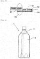
- Plastic bottles such as PET bottles are now widely used as containers for beverages such as carbonated beverages. These containers are often equipped with plastic labels for labeling (indication), decoration, and/or functionalization.
- stretch labels each including a stretch film as a base, where the stretch film has excellent elasticity.
- Each stretch label is attached to an objective article such as a container typically in the following manner.
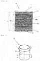
- the stretch label is formed into a cylindrical shape to give a stretch sleeve label having a diameter equal to or slightly smaller than the diameter of the objective article.
- the stretch sleeve label is extended (elongated) by an external force and is fitted onto the objective article. The external force is then released, and this allows the label to contract (spontaneously contract) and to be attached to the objective article.
- the stretch labels require extensibility (elongation properties) and resilience at excellent levels.
- a known example of the stretch labels is a stretch label using a film for stretch labels (see Patent Literature (PTL) 1).
- the film includes a linear low-density polyethylene having a density of 0.905 to 0.940 g/cm 3 and has a thickness of 30 to 150 ⁇ m, where the linear low-density polyethylene is polymerized using a single-site metallocene catalyst.
- the film has a strain of not greater than 7% at zero stress and has a permanent set of not greater than 1.5%. The strain at zero stress and the permanent set are determined based on the measurement of a hysteresis curve at 25% or less, where the hysteresis curve is plotted when the film is deformed laterally at a rate of 300 mm/min.
- stretch labels are to be attached
- those having complicated shapes such as PET bottles having a large difference in diameter in the barrel, occupy larger and lager proportions.
- the stretch labels require still more excellent stretch properties (extensibility and resilience) so as to conform to objective articles and to offer excellent fittability even when the objective articles to which the stretch labels are to be attached have complicated shapes.
- the inventors of the present invention made attempts to produce a stretch label by preparing a stretch film from a softer resin (e.g., a polyethylene resin having a lower density) as compared with conventional equivalents, so as to allow the stretch label to have better stretch properties.
- a softer resin e.g., a polyethylene resin having a lower density
- MD machine direction
- the stretch label obtained using the stretch film is disadvantageously susceptible to breakage typically in a process of transporting the stretch label after being attached to the objective article.
- a stretch label produced from a stretch film using a hard resin e.g., a high-density polyethylene
- a stretch label produced from a stretch film using a hard resin is resistant to breakage and to reduction in producibility, but disadvantageously suffers from reduction in stretch properties. Accordingly, it has been difficult to provide a stretch label that meets all the requirements for stretch properties, producibility, and resistance to breakage (breakage resistance) all at excellent levels.
- the present invention has an object to provide a stretch label that has excellent stretch properties and still offers producibility and breakage resistance at excellent levels.
- the stretch film includes a base layer part and surface layers disposed on or over both sides of the base layer part.
- the base layer part has a multilayer configuration including 3 to 65 layers that contain a polyethylene resin as a principal component and independently have a density within a specific range.
- Each of the layers containing a polyethylene resin as a principal component and having a density within a specific range differs in density from another adjacent one.
- the inventors have found that this stretch label has excellent stretch properties and still offers producibility and breakage resistance at excellent levels. The present invention has been made based on these findings.
- the present invention provides a stretch label including a stretch film.
- the stretch film includes a base layer part, and surface layers disposed on or over both sides of the base layer part.
- the base layer part includes 3 to 65 layers E.
- the layers E each contain a polyethylene resin in a content in the layer of 60% by weight or more and independently have a density of 0.850 to 0.945 g/cm 3 .
- Each of the layers E in the base layer part differs in density from another adjacent layer E.
- the layers E in the base layer part may include at least one layer A and at least one layer B.
- the layer A contains a polyethylene resin in a content in the layer of 60% by weight or more and has a density of 0.850 to 0.930 g/cm 3 .
- the layer B contains a polyethylene resin in a content in the layer of 60% by weight or more and has a density of 0.945 g/cm 3 or less, where the density of the layer B is higher than the density of the layer A by 0.005 g/cm 3 or more.
- the base layer part may have two or more interfaces each between an adjacent pair of the layer A and the layer B.
- the layers E in the base layer part may include the layer A and the layer B disposed in alternate order in a total number of 3 to 65.
- the surface layers may be layers each containing a polyethylene resin in a content in the layer of 60% by weight or more and having a density of 0.900 to 0.945 g/cm 3 .
- the present invention further provides a method for producing the stretch label.
- the method includes the step of preparing the stretch film.
- the step of preparing the stretch film includes a first substep, a second substep, and a third substep.
- a material (a) to form the layer A, a material (b) to form the layer B, and a material (c) to form the surface layers are independently melted.
- the material (a) and the material (b) each melted in the first substep are stacked on each other to form a multilayer assembly.
- the material (c) melted in the first substep is stacked on both sides of the multilayer assembly formed in the second substep.
- the stretch label according to the present invention includes a stretch film as a label base.
- the stretch film includes a base layer part, and surface layers disposed on or over both sides of the base layer part.
- the base layer part has a multilayer configuration including 3 to 65 layers, where each of the layers independently contains a polyethylene resin as a principal component and has a density within the specific range.
- Each of the layers containing a polyethylene resin as a principal component and having a density within a specific range differs in density from another adjacent one.
- the stretch label according to the present invention as having this configuration, has extensibility and resilience both at excellent levels.
- the stretch film less elongates upon formation of a print layer. This allows the print layer to be easily formed at a suitable position to give the stretch label with excellent producibility.
- the stretch label is resistant to breakage typically in the step of transporting the resulting labeled article after attachment of the stretch label to the objective article. Consequently, the stretch label according to the present invention is particularly useful as a stretch label to be attached to an objective article having a complicated shape.
- the terms “extensibility” and “resilience” are also generically referred to as “stretch properties” or "elasticity”.
- the term “extensibility” refers to such a property that the stretch film or the stretch label can be stretched, and/or refers to easiness to extend.
- the term “resilience” refers to such a property that the stretch film or the stretch label contracts (restitutes) by an elastic force when it is extended by an external force and then the external force is released.
- spontaneous contraction refers to such a phenomenon that, when the stretch film or the stretch label is extended by an external force and then the external force is released, the stretch film or the stretch label (spontaneously) contracts due to the resilience of the stretch film or the stretch label.
- the stretch label according to the present invention includes a stretch film.
- the stretch film (namely, stretch film included in the stretch label according to the present invention) is also referred to as a "stretch film in the present invention".
- the stretch label according to the present invention may further include one or more other layers than the stretch film in the present invention, within ranges not adversely affecting the advantageous effects of the present invention.
- the stretch film in the present invention has surface layers disposed on or over both sides of a base layer part.
- the stretch film in the present invention includes a base layer part, and surface layers disposed on or over both sides of the base layer part.
- the stretch film in the present invention has a layer configuration including the surface layer, the base layer part, and the surface layer disposed in this order. In the layer configuration, the surface layers are preferably directly disposed on the base layer part.
- the surface layers in the stretch film in the present invention may be identical layers or different layers. When the surface layers are different layers, the surface layers may be different typically in composition of resins constituting the surface layers and/or different in layer thickness.
- the stretch film in the present invention may further include one or more layers other than the base layer part and the surface layers, within ranges not adversely affecting the object of the present invention.
- Non-limiting examples of the other layers than the base layer part and the surface layers include antistatic layers and anchor coat layers.
- the stretch film in the present invention may have undergone, on its surface, a common surface treatment as needed, such as corona discharge treatment, primer treatment, and/or flame treatment.
- the base layer part in the stretch film in the present invention includes 3 to 65 layers, where each of the layers independently contains a polyethylene resin in a content in the layer of 60% by weight or more and has a density of 0.850 to 0.945 g/cm 3 .
- the stretch film in the present invention offers excellent stretch properties and still has strength at a certain level. This allows the stretch label according to the present invention to have stretch properties, producibility, and breakage resistance all at high levels.
- the term "base layer part” refers to a portion between the surface layers in the stretch film in the present invention.
- the "layer containing a polyethylene resin in a content in the layer of 60% by weight or more and having a density of 0.850 to 0.945 g/cm 3 " is also referred to as a "layer E".
- the base layer part has a multilayered structure including layers E stacked on each other in a number of 3 to 65. Each of the layers E in the base layer part differs in density from another adjacent layer E.
- the base layer part may include one or more layers E that are not adjacent to another layer E.
- the base layer part may further include one or more layers other than the layers E, within ranges not adversely affecting the advantageous effects of the present invention, but is more preferably devoid of the other layers than the layers E.
- the layers E each contain a polyethylene resin as an essential component.
- the layers E may independently contain each of different polyethylene resins alone or in combination.
- polyethylene resin refers to a polymer derived from a monomer component or components essentially including ethylene.
- polyethylene resin refers to a polymer including a constitutional unit (structural unit) derived from ethylene in molecule (per molecule).
- Non-limiting examples of the polyethylene resins include ethylene homopolymers; and copolymers (ethylene copolymers) each derived from monomer components essentially including ethylene and one or more monomer components (monomer components other than ethylene).
- Non-limiting examples of the monomer components other than ethylene include ⁇ -olefins; vinyl monomers such as vinyl chloride; unsaturated carboxylic acids such as (meth)acrylic acid, maleic acid, fumaric acid, crotonic acid, itaconic acid, citraconic acid, and 5-norbornene-2,3-dicarboxylic acid; unsaturated carboxylic acid anhydrides such as maleic anhydride, citraconic anhydride, 5-norbornene-2,3-dicarboxylic anhydride, and tetrahydrophthalic anhydride; unsaturated carboxylic esters such as methyl (meth)acrylate, ethyl (meth)acrylate, propyl (meth)acrylate, butyl (meth)acrylate, 2-ethylhexyl (meth)acrylate, 2-hydroxyethyl (meth)acrylate, 3-hydroxypropyl (meth)acrylate, glycidyl (meth)acrylate
- Non-limiting examples of the ⁇ -olefin include C 3 -C 20 ⁇ -olefins such as propylene, 1-butene, 1-pentene, 4-methyl-1-pentene, 1-hexene, 1-heptene, 1-octene, 1-nonene, and 1-decene, of which C 4 -C 8 ⁇ -olefins are preferred.
- C 4 -C 8 ⁇ -olefins are preferred.
- Each of different ⁇ -olefins may be used alone or in combination.
- ethylene copolymers examples include, but are not limited to, ethylene- ⁇ -olefin copolymers each derived from monomer components essentially including ethylene and one or more ⁇ -olefins; ethylene-vinyl acetate copolymers (EVAs); ethylene-carboxylic acid copolymers such as ethylene-acrylic acid copolymers (EAAs) and ethylene-methacrylic acid copolymers (EMAAs); and ethylene-carboxylic ester copolymers such as ethylene-ethyl acrylate copolymers (EEAs) and ethylene-methyl methacrylate copolymers (EMMAs).
- EVAs ethylene-vinyl acetate copolymers
- EAAs ethylene-acrylic acid copolymers
- EEMAAs ethylene-methacrylic acid copolymers
- EMMAs ethylene-carboxylic ester copolymers
- the polyethylene resin may also be a metallocene-catalyzed polyethylene resin, which is a polyethylene resin prepared via polymerization using a metallocene catalyst.
- the metallocene catalyst may be selected from known or common metallocene catalysts for olefin polymerization.
- Non-limiting examples of the polyethylene resin include low-density polyethylenes (LDPEs) and linear low-density polyethylenes (LLDPEs).
- LDPE low-density polyethylenes
- LLDPE linear low-density polyethylenes
- the "LDPE” refers to a polyethylene that includes a constitutional unit derived from ethylene, is produced by a high-pressure process, and has a low density of about 0.850 to about 0.945 g/cm 3 .
- the “LLDPE” refers to a polyethylene that includes a constitutional unit derived from ethylene, is produced by a medium- or low-pressure process, includes short-chain branches, and has a low density of about 0.850 to about 0.945 g/cm 3 .
- the polyethylene resins in the layers E are not limited, but are preferably selected from ethylene homopolymers and ethylene- ⁇ -olefin copolymers.
- the polyethylene resins are preferably selected from LDPEs and LLDPEs, and more preferably selected from LLDPEs.
- the polyethylene resins in the layers E are more preferably selected from metallocene-catalyzed polyethylene resins, which are polyethylene resins prepared via polymerization using a metallocene catalyst, and particularly preferably selected from metallocene-catalyzed LLDPEs such as metallocene-catalyzed ethylene- ⁇ -olefin copolymers. These are preferred from the viewpoint of film-formability/workability.
- the content of the constitutional unit derived from ethylene based on the total amount (100% by weight) of the polyethylene resin in each layer E namely, the content of ethylene based on the total amount (100% by weight) of all monomer components constituting the polyethylene resin in each layer E is not limited, but is preferably 50% by weight or more, more preferably 70% by weight or more, furthermore preferably 80% by weight or more, and particularly preferably 85% by weight or more.
- the range is preferred from the viewpoint of elasticity.
- the content of the constitutional unit(s) derived from ⁇ -olefin(s) based on the total amount (100% by weight) of the ethylene- ⁇ -olefin copolymer namely, the content of ⁇ -olefin(s) based on the total amount (100% by weight) of all monomer components constituting the ethylene- ⁇ -olefin copolymer is not limited, but is preferably from greater than 0% by weight to 50% by weight, more preferably 1% to 30% by weight, and particularly preferably 1% to 15% by weight. The range is preferred from the viewpoint of elasticity.
- the total content of the constitutional unit derived from ethylene and the constitutional unit(s) derived from ⁇ -olefin(s) is not limited, but is preferably 80% by weight or more, more preferably 90% by weight or more, and particularly preferably 95% by weight or more, based on the total amount (100% by weight) of the polyethylene resin.
- the polyethylene resins to be contained in the layers E may also be selected from commercial products. Such commercial products are available in the market and are exemplified by metallocene-catalyzed LLDPEs such as UMERIT 4540F, UMERIT 3540F, UMERIT 2540F, UMERIT 1540F, UMERIT 0540F, UMERIT 2040FC, UMERIT 1520F, UMERIT 0520F, and UMERIT 715FT each from UBE-MARUZEN POLYETHYLENE CO., LTD., and Evolue SP0540, Evolue SP1540, Evolue SP1520, and Evolue SP2040 each from Prime Polymer Co., Ltd.; metallocene-catalyzed ethylene/ ⁇ -olefin copolymers such as KERNEL KF260T, KERNEL KF360T, KERNEL KF380, and KERNEL KS340T each from Japan Polyethylene Corporation; LDPEs such as F234 from UBE-
- the content of the polyethylene resin in each layer E is 60% by weight or more and is preferably 80% by weight or more, and furthermore preferably 90% by weight or more, based on the total weight (100% by weight) of the layer E.
- the upper limit of the content is not limited, but is 100% by weight, and may be 98% by weight.
- the layer E if containing the polyethylene resin in a content less than 60% by weight, may have insufficient elasticity.
- the "content of the polyethylene resin" refers to the total content of all the polyethylene resins contained in the layer E (one layer E).
- the layers E may each independently further contain one or more additives within ranges not adversely affecting the advantageous effects of the present invention.
- additives include lubricants, fillers, thermal stabilizers, antioxidants, ultraviolet absorbers, antistatic agents, anti-fogging agents, flame retardants, and colorants.
- each layer E is 0.850 to 0.945 g/cm 3 , and is preferably 0.870 to 0.940 g/cm 3 , and more preferably 0.890 to 0.935 g/cm 3 .
- the layers E if having a density lower than 0.850 g/cm 3 , cause the base layer part to be excessively soft. This causes the stretch film to more readily elongates upon the formation of a print layer on the stretch film and causes the stretch label to be produced with lower producibility. In addition, this stretch label has lower strength to offer lower breakage resistance.
- the layers E if having a density higher than 0.945 g/cm 3 , causes the stretch label to have lower stretch properties.
- the number of the layers E in the base layer part is 3 to 65 and is preferably 5 to 33, and more preferably 9 to 33.
- the base layer part if including less than three layers E, less effectively causes the stretch film to have higher strength due to the multilayer structure of the base layer part, and causes the stretch label to be produced with lower producibility and/or to have lower breakage resistance. This is probably because of a small number of an interface (interface between two layers) in the base layer part.
- the base layer part if including more than sixty-five (65) layers E, includes the layers E with an excessively small thickness (thickness per layer) when the stretch film is controlled to have a thickness (total thickness) within such a range as to be suitable to constitute a stretch label.
- This causes the stretch film and the stretch label to offer lower resilience.
- the stretch film may become iridescent.
- the layers E in the base layer part are preferably, but not limitatively, disposed on each other without the medium of another layer (e.g., an adhesive layer).
- each of the layers E in the base layer part differs in density from another adjacent layer E.
- the difference in density of each layer E from another adjacent layer E contributes to better producibility and better breakage resistance of the stretch label. This is probably because the difference causes the interface between one layer E and another adjacent layer E to have a greater effect and thereby allows the stretch film to have higher strength.
- the difference in density between adjacent layers E is not limited, but is preferably 0.005 g/cm 3 or more, and more preferably 0.009 g/cm 3 or more.
- the base layer part may have a density not limited, but preferably 0.890 to 0.940 g/cm 3 , more preferably 0.900 to 0.930 g/cm 3 , and particularly preferably 0.910 to 0.925 g/cm 3 .
- the base layer part when having a density of 0.890 g/cm 3 or more, does not become excessively soft. This configuration advantageously eliminates or minimizes easiness of the stretch film to elongate upon the formation of a print layer on the stretch film and eliminates or minimizes reduction in producibility of the stretch label. The configuration also advantageously eliminates or minimizes reduction in breakage resistance accompanied with reduction in strength of the stretch label.
- the base layer part when having a density of 0.940 g/cm 3 or less, advantageously eliminates or minimizes reduction in stretch properties of the stretch label.
- the base layer part preferably, but not limitatively, includes at least one layer A and at least one layer B as the layers E.
- the layer A is a layer that contains a polyethylene resin in a content in the layer of 60% by weight or more and has a density of 0.850 to 0.930 g/cm 3 .
- the layer B is a layer that contains a polyethylene resin in a content in the layer of 60% by weight or more and has a density of 0.945 g/cm 3 or less, where the density of the layer B is higher than the density of the layer A by 0.005 g/cm 3 or more.
- the base layer part preferably includes the layer A and the layer B disposed adjacent to each other and preferably has two or more interfaces between an adjacent pair of the layer A and the layer B.
- the “layer A” refers to the "layer that contains a polyethylene resin in a content in the layer of 60% by weight or more and has a density of 0.850 to 0.930 g/cm 3 ".
- the “layer B” refers to the "layer that contains a polyethylene resin in a content in the layer of 60% by weight or more and has a density of 0.945 g/cm 3 or less, where the density of the layer B is higher than the density of the layer A by 0.005 g/cm 3 or more".
- the base layer part that includes at least one layer A and at least one layer B as the layers E, and has two or more interfaces between an adjacent pair of the layer A and the layer B is also referred to as a "base layer part according to the preferred embodiment".
- the density of the layer A in terms of lower limit is 0.850 g/cm 3 or more, and is preferably 0.870 g/cm 3 or more, and more preferably 0.890 g/cm 3 or more.
- the density of the layer A in terms of upper limit is 0.930 g/cm 3 or less, and is preferably 0.925 g/cm 3 or less, and more preferably 0.920 g/cm 3 or less.
- the layer A as having a density of 0.850 g/cm 3 or more, allows the base layer part to resist becoming excessively soft. This configuration advantageously eliminates or minimizes reduction in breakage resistance and producibility of the stretch label.
- the layer A, as having a density of 0.930 g/cm 3 or less advantageously eliminates or minimizes reduction in stretch properties of the stretch label.
- the density of the layer B is higher than the density of the layer A by 0.005 g/cm 3 or more, and preferably by 0.009 g/cm 3 or more.
- the density of the layer B in terms of upper limit is 0.945 g/cm 3 or less, and is preferably 0.940 g/cm 3 or less, and more preferably 0.935 g/cm 3 or less.
- the density of the layer B in terms of lower limit is not limited, as long as being higher than the density of the layer A by 0.005 g/cm 3 or more, but is preferably 0.900 g/cm 3 or more, more preferably 0.905 g/cm 3 or more, and furthermore preferably 0.910 g/cm 3 or more.
- the layer B as having a density higher than the density of the layer A by 0.005 g/cm 3 or more, advantageously more readily effectively contributes to higher strength due to multilayer lamination, when the layer A and layer B are disposed adjacent to each other. This is probably because the interface between the layer A and the layer B is formed distinctly when the layer A and the layer B are stacked on each other typically by coextrusion. If the difference in density between the layer A and the layer B is less than 0.005 g/cm 3 , adjacent layers are more easily mixed with each other to form a disordered interface between the layers when the layer A and the layer B are disposed adjacent to each other and when these layer are stacked on each other typically by coextrusion. This may cause the multilayer lamination to less effectively offer higher strength.
- the layer B as having a density of 0.945 g/cm 3 or less, advantageously eliminates or minimizes reduction in stretch properties of the stretch label.
- the difference in density between the layer A and the layer B ((layer B density) minus (layer A density)) is not limited, but is preferably 0.005 g/cm 3 or more, and more preferably 0.009 g/cm 3 or more.
- the number of interfaces each between an adjacent pair of the layer A and the layer B is 2 or more, and is preferably 4 or more, and more preferably 8 or more.
- the number of the layer A in the base layer part according to the preferred embodiment is 1 or more (e.g., 1 to 33), preferably 2 or more (e.g., 2 to 17), and more preferably 3 or more (e.g., 3 to 17).
- the number of the layer B in the base layer part according to the preferred embodiment is 1 or more (e.g., 1 to 33), preferably 2 or more (e.g., 2 to 17), and more preferably 3 or more (e.g., 3 to 17).
- the total number of the layer A and the layer B is not limited, but is preferably 3 to 65, more preferably 5 to 33, and furthermore preferably 9 to 33.
- the base layer part according to the preferred embodiment may further include one or more layers other than the layers E (layers other than the layers A and the layers B).
- the base layer part according to the preferred embodiment is preferably, but not limitatively, devoid of layers E other than the layers A and the layers B. Namely, every layer E in the base layer part is preferably the layer A or the layer B.
- every layer E is preferably the layer A or the layer B, and the layer A and the layer B are preferably disposed in alternate order.
- the layer A and the layer B are more preferably disposed directly on each other in alternate order without the medium of any other layer.
- the direct lamination of the layer A and the layer B on each other forms an interface between the layer A and the layer B, and this advantageously contributes to higher strength of the stretch film in the present invention and the stretch label according to the present invention.
- the presence of two or more interfaces each between an adjacent pair of the layer A and the layer B advantageously contributes to still higher strength of the stretch film in the present invention and the stretch label according to the present invention.
- the multilayer configuration of the base layer part according to the preferred embodiment is not limited, but is exemplified by multilayer configurations each including a constitutional repeating unit of "layer A/layer B", such as multilayer configurations of (layer A/layer B/layer A/layer B/.../layer A/layer B/layer A), (layer B/layer A/layer B/layer A/.../layer B/layer A/layer B), (layer A/layer B/layer A/layer B/.../layer A/layer B), and (layer B/layer A/layer B/layer A/.../layer B/layer A/layer B/layer A).
- the layer A and the layer B are preferably disposed on each other without the medium of any other layer.
- the layer B is preferably disposed adjacent to at least one side of every layer A.
- all the layers A are preferably formed from an identical material; and all the layers B are preferably formed from an identical material. Specifically, it is preferred that every layer A is formed from an identical material; and every layer B is formed from an identical material. Namely, it is preferred that all the layer A are layers having a composition identical to each other; and all the layers B are layers having a composition identical to each other.
- the surface layers in the stretch film in the present invention are layers (resin layers) disposed on or over both sides of the base layer part.
- the surface layers are not limited, as long as they are resin layers having stretch properties, and as long as a print layer can be formed on the resin layers.
- the resin contained in the surface layers is not limited, but may be selected from thermoplastic resins including polyolefin resins, styrenic elastomers such as styrene-butadiene elastomers, and other thermoplastic elastomers. Among them, polyolefin resins are preferred. Each of different resins may be used alone or in combination.
- Non-limiting examples of the polyolefin resins include polyethylene resins; polymers (polypropylene resins) derived from one or more monomer components essentially including propylene; ionomers; and cycloolefin polymers. Among them, polyethylene resins are preferred from the viewpoints of stretch properties and producibility. Each of different polyolefin resins may be used alone or in combination.
- the polyethylene resin which may be contained in the surface layers is not limited, but is preferably selected from ethylene homopolymers, ethylene- ⁇ -olefin copolymers, and EVAs, and particularly preferably selected from ethylene homopolymers and ethylene- ⁇ -olefin copolymers.
- the polyethylene resin which may be contained in the surface layers is preferably selected from LDPEs, LLDPEs, and EVAs, and more preferably selected from LLDPEs.
- LLDPEs preferred are metallocene-catalyzed LLDPEs, which are LLDPEs prepared via polymerization using a metallocene catalyst.
- the metallocene-catalyzed LLDPEs are preferred because they have uniform molecular weights, readily have resin flow stability, and offer high film-formability/workability.
- the content of the vinyl acetate component (VA component) is preferably 1% to 10% by weight based on the total weight (100% by weight) of the surface layers.
- VA component vinyl acetate component
- Each of different polyethylene resins may be used alone or in combination.
- the content of the constitutional unit derived from ethylene in the polyethylene resin (100% by weight) which may be contained in the surface layers, namely, the content of ethylene in all the monomer components (100% by weight) constituting the polyethylene resin is not limited, but is preferably 50% by weight or more, and more preferably 70% to 99% by weight. The range is preferred from the viewpoint of elasticity.
- the content of the constitutional unit(s) derived from the ⁇ -olefin(s) in the ethylene- ⁇ -olefin copolymer (100% by weight), namely, the content of the ⁇ -olefin(s) in all the monomer components (100% by weight) constituting the ethylene- ⁇ -olefin copolymer is not limited, but preferably from greater than 0% by weight to 50% by weight, and more preferably 1% to 30% by weight. The range is preferred from the viewpoint of elasticity.
- the content of a constitutional unit(s) derived from a monomer component(s) other than the ethylene and the ⁇ -olefins in the ethylene- ⁇ -olefin copolymer (100% by weight) is not limited, but is preferably 10% by weight or less, and more preferably 5% by weight or less.
- the polyethylene resin which may be contained in the surface layer may also be selected from commercial products.
- commercial products for example, the polyethylene resins exemplified and described as the commercial products of the polyethylene resin to be contained in the layers E are available in the market.
- Each of the surface layers may contain the polyolefin resin in a content of preferably 60% by weight or more, more preferably 80% by weight or more, and furthermore preferably 90% by weight or more, based on the total weight (100% by weight) of the surface layer.
- the upper limit of the content is not limited, but is 100% by weight, and may be 98% by weight.
- Each of the surface layers, when containing the polyolefin resin in a content of 60% by weight or more advantageously contributes to better breakage resistance and better producibility without adversely affecting elasticity.
- the "content of the polyolefin resin” refers to the total content of all the polyolefin resins contained in each surface layer.
- the surface layers may each contain one or more additives within ranges not adversely affecting the advantageous effects of the present invention.
- additives include lubricants, fillers, thermal stabilizers, antioxidants, ultraviolet absorbers, antistatic agents, anti-fogging agents, flame retardants, and colorants.
- the surface layers may each have a density not limited, but preferably 0.900 to 0.945 g/cm 3 , more preferably 0.910 to 0.940 g/cm 3 , and furthermore preferably 0920 to 0.935 g/cm 3 .
- the surface layers when having a density of 0.900 g/cm 3 or more, advantageously have suitable hardness and do not adversely affect breakage resistance.
- these surface layers advantageously allow the stretch film in the present invention to less elongate upon the formation of a print layer on the stretch film and to give the stretch label according to the present invention with better producibility.
- the surface layers if having a density higher than 0.945 g/cm 3 , may cause the stretch label to have lower stretch properties.
- the stretch film in the present invention includes the base layer part and the surface layers.
- the surface layers are respectively disposed on or over both sides of the base layer part, namely, one of the surface layers is disposed on or over one side of the base layer part, and the other surface layer is disposed on or over the other side of the base layer part.
- the stretch film in the present invention may contain polyethylene resins in a content not limited, but preferably 70% by weight or more, more preferably 80% by weight or more, and furthermore preferably 90% by weight or more, based on the total weight (100% by weight) of the stretch film in the present invention.
- the upper limit of the content is not limited, but may be 100% by weight, or may be 98% by weight.
- the stretch film when containing the polyethylene resins in a content of 70% by weight or more, advantageously offers better elasticity.
- the "content of the polyethylene resins" refers to the total content of all the polyethylene resins contained in the stretch film in the present invention.
- the stretch film in the present invention may have a density not limited, but preferably 0.900 to 0.940 g/cm 3 , more preferably 0.910 to 0.930 g/cm 3 , and furthermore preferably 0.915 to 0.925 g/cm 3 .
- the stretch film when having a density of 0.900 g/cm 3 or more, the stretch film (particularly the base layer part) does not become excessively soft. This advantageously eliminates or minimizes reduction in breakage resistance and producibility of the stretch label.
- the stretch film when having a density of 0.940 g/cm 3 or less, advantageously allows the stretch label to resist reduction in stretch properties.
- the stretch film in the present invention may have a thickness (total thickness) not limited, but preferably 10 to 100 ⁇ m, more preferably 20 to 60 ⁇ m, and furthermore preferably 25 to 50 ⁇ m.
- the stretch film when having a thickness of 10 ⁇ m or more, has high strength and advantageously contributes to better producibility and better breakage resistance of the stretch label.
- the stretch film when having a thickness of 100 ⁇ m or less, advantageously allows the stretch label to be more readily extended and to have better stretch properties.
- the present invention significantly effectively contributes to better producibility of a stretch label when the stretch label includes a relatively thin stretch film. This is because such a relatively thin stretch film may readily elongate upon the formation of a print layer, and this may readily cause lower productivity.
- the surface layers may each have a thickness (thickness per layer) not limited, but preferably 1 to 13 ⁇ m, more preferably 2 to 7.5 ⁇ m, and furthermore preferably 2.5 to 6.5 ⁇ m.
- the surface layers when having a thickness within the range, advantageously sufficiently offer the effects of providing the surface layers.
- the individual surface layers in the stretch film in the present invention may have an identical thickness or different thicknesses.
- the base layer part may have a thickness not limited, but preferably 8 to 80 ⁇ m, more preferably 10 to 50 ⁇ m, and furthermore preferably 15 to 40 ⁇ m.
- the base layer part when having a thickness within the range, advantageously allows the stretch label to have better stretch properties and to offer better producibility and breakage resistance significantly effectively.
- the layers E may each have a thickness (thickness per layer) not limited, but preferably 0.5 ⁇ m or more, and more preferably 1 ⁇ m or more.
- the layers E if having a thickness per layer of less than 0.5 ⁇ m, may lose their hardness, and this may cause the stretch label to suffer from reduction in producibility and/or breakage resistance.
- the thicknesses of the plurality of the layers E in the stretch film in the present invention may be partially or entirely identical to one another, or different from one another.
- the layer(s) A may have a thickness (thickness per layer) not limited, but preferably 0.5 ⁇ m or more, and more preferably 1 ⁇ m or more.
- the layer(s) A if having a thickness per layer less than 0.5 ⁇ m, may lose hardness inherent to the resin, and this may cause the stretch label to suffer from reduction in producibility and/or breakage resistance.
- the stretch film in the present invention includes two or more layers A, the thicknesses of the layers A may be partially or entirely identical to each other, or may be different from each other.
- the layer(s) B may have a thickness (thickness per layer) not limited, but preferably 0.5 ⁇ m or more, and more preferably 1 ⁇ m or more.
- the layer(s) B if having a thickness per layer less than 0.5 ⁇ m, may lose hardness inherent to the resin, and this may cause the stretch label to suffer from reduction in producibility and/or breakage resistance.
- the stretch film in the present invention includes two or more layers B, the thicknesses of the layers B may be partially or entirely identical to each other, or may be different from each other.
- the ratio of the thickness of the surface layers (total thickness of all the surface layers) to the thickness of the base layer part is not limited, but is preferably less than 1:1 (the thickness of the base layer part is preferably greater than the total thickness of the surface layers), more preferably from 1:10 to 1:1.5, and furthermore preferably from 1:5 to 1:2. If the ratio is greater than 1:1 (if the total thickness of the surface layers is greater than the thickness of the base layer part), the present invention may offer smaller advantageous effects.
- the ratio of the thickness of the layer(s) A (total thickness of all the layers A) to the thickness of the layer(s) B (total thickness of all the layers B) is not limited, but preferably from 1:10 to 10:1, more preferably from 1:6 to 6:1, and furthermore preferably from 1:4 to 4:1. If the ratio is greater than 10:1 (if the layers A have a total thickness greater than 10 times the total thickness of the layers B), the stretch label may have lower stretch properties. In contrast, if the ratio is less than 1:10 (if the layers B have a total thickness greater than 10 times the total thickness of the layers A), the stretch label may suffer from reduction in producibility and/or breakage resistance.
- the stretch film in the present invention when being transparent, may have a haze not limited, but preferably 10% or less, more preferably 7% or less, and furthermore preferably 5% or less.
- the haze is determined in conformity to JIS K 7136 in terms of 40 ⁇ m thickness and is indicated in percent (%). Assume that the stretch film has a haze greater than 10%; and that this stretch film is applied to a stretch label (back printed stretch label) in which a print is applied to an inner side of the stretch film, and the print is to be seen through the stretch film, where the inner side is a side which will face a container when the stretch label is attached to the container.
- the print When this stretch label is processed into a product, the print may look hazed, and the stretch label may offer inferior decorativeness.
- the stretch film is allowed to be non-transparent.
- the stretch film even when having a haze greater than 10%, is sufficiently usable in the other applications.
- the stretch label according to the present invention includes the stretch film in the present invention.
- the stretch label according to the present invention may further include one or more layers other than the stretch film in the present invention.
- the stretch label according to the present invention has stretch properties in at least one direction and is extensible (stretchable) in one direction upon use.
- the other layers which may be contained in the stretch label according to the present invention in addition to the stretch film in the present invention are not limited, but may be selected typically from print layers, adhesive layers (e.g., pressure-sensitive adhesive layers and heat-sensitive adhesive layers), protective layers, anchor coat layers, primer coating layers, coating layers, and antistatic layers.
- adhesive layers e.g., pressure-sensitive adhesive layers and heat-sensitive adhesive layers
- protective layers e.g., anchor coat layers, primer coating layers, coating layers, and antistatic layers.
- the print layer is not limited and may be selected from known or common print layers for use in stretch labels.
- the print layers include designed print layers (e.g., color print layers) and background print layers.
- the designed print layers illustrate figures and designs typically of trade names, illustrations, and handling precautions.
- the background print layers are each indicated by a single color such as white.
- the print layer may be disposed on or over either one or both sides of the stretch film in the present invention.
- the print layer may be disposed entirely or partially on or over a surface (the surface on which the print layer is disposed) of the stretch film in the present invention.
- the print layer may be a single layer or a multilayer.
- the print layer preferably, but not limitatively, contains a binder resin as an essential component and, as needed, further contains one or more additives such as coloring pigments, lubricants, dispersing agents, and antifoaming agents.
- coloring pigments include blue, red, yellow, black, and white pigments.
- the print layer may contain each of different binder resins alone or in combination and may contain each of different coloring pigments or any other additives alone or in combination.
- the binder resins are not limited and may be selected typically from known or common resins for use as binder resins in print layers and printing inks.
- Non-limiting examples of the binder resins include acrylic resins, urethane resins, polyester resins, polyamide resins, cellulose resins (including nitrocellulose resins), and vinyl chloride-vinyl acetate copolymer resins.
- the coloring pigments are not limited and may be selected from known or common coloring pigments for use in print layers and printing inks.
- Non-limiting examples of the coloring pigments include white pigments such as titanium dioxide; cyan pigments such as copper phthalocyanine blue; and any other coloring pigments such as carbon black, aluminum flake, and mica.
- the coloring pigments may be selected and used according to the intended use.
- Examples of the coloring pigments also include extender pigments such as alumina, calcium carbonate, barium sulfate, silica, and acrylic beads. The extender pigments may be used for a purpose such as gloss adjustment
- the print layer may have a thickness not limited, but typically preferably 0.1 to 10 ⁇ m, and more preferably 0.3 to 5 ⁇ m.
- the print layer if having a thickness less than 0.1 ⁇ m, may be difficult to be provided uniformly. Such a nonuniform print layer may suffer from partial "blur (poor print quality)" and may cause the stretch label to have inferior decorativeness.
- the nonuniform print layer may fail to be printed as designed.
- the print layer if having a thickness greater than 10 ⁇ m, may consume a large amount of the printing ink and may increase the cost.
- the excessively thick print layer may fail to be formed uniformly by coating, and/or may become brittle and become susceptible to peeling off, and/or may lead to lower stretch properties.
- the protective layer is a layer that is disposed to protect the stretch film and/or the print layer.
- the protective layer is not limited and may be selected from known or common protective layers for use in stretch labels.
- the protective layer is preferably, but not limitatively, a protective layer (protective coating layer) formed from (derived from) a coating composition.
- the protective layer may be disposed on or over either one or both sides of the stretch film in the present invention.
- the protective layer may be disposed on or over a surface of the print layer of the stretch film in the present invention, and/or on or over a surface of the stretch film in the present invention.
- the protective layer may be disposed entirely or partially on or over at least one side of the stretch film in the present invention.
- the protecting coating layer is preferably, but not limitatively, transparent.
- the protective coating layer when being transparent, may be colored or colorless, but is preferably colorless.
- the protective layer may have a thickness not limited, but typically preferably 0.1 to 10 ⁇ m.
- the protective coating layer preferably, but not limitatively, contains a binder resin and a lubricant (e.g., a wax) as essential components.
- the protective coating layer may contain one or more additives as needed.
- the protective coating layer may contain each of different binder resins alone or in combination and may contain each of different lubricants alone or in combination.
- the binder resins for use in the protective coating layer are not limited and may be selected typically from known or common resins for use as binder resins in coating layers and coating compositions.
- Non-limiting examples of the binder resins include the binder resins exemplified and described as binder resins in the print layer.
- the lubricants are not limited and may be selected typically from known or common lubricants for use in coating layers and coating compositions.
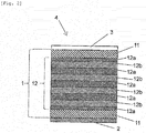
- Figs. 1 to 3 are schematic views (local sectional views) of stretch labels according to embodiments of the present invention.
- the stretch label 4 according to the present invention illustrated in Fig. 1 includes a stretch film 1 in the present invention, a print layer 2, and a protective coating layer 3.
- the print layer 2 is disposed on one side of the stretch film 1 in the present invention.
- the protective coating layer 3 is disposed on the other side of the stretch film 1 in the present invention.
- the stretch film 1 in the present invention includes a base layer part 12 and surface layers 11.
- the surface layers 11 are respectively disposed on both sides of the base layer part 12 (one surface layer per side).
- the base layer part 12 is constituted by layers E 12c disposed on each other (adjacent to each other) in a total number of 9. Each of the layers E 12c differs in density from another adjacent layer E 12c.
- the surface layers 11 are disposed directly on the base layer part 12 without the medium of any other layer.
- the stretch label 4 according to the present invention illustrated in Fig. 2 includes a stretch film 1 in the present invention, a print layer 2, and a protective coating layer 3.
- the print layer 2 is disposed on one side of the stretch film 1 in the present invention.
- the protective coating layer 3 is disposed on the other side of the stretch film 1 in the present invention.
- the stretch film 1 in the present invention includes a base layer part 12, and surface layers 11.
- the surface layers 11 are disposed on both sides of the base layer part 12 (one surface layer per one side).
- the base layer part 12 includes, as layers E, layers A 12a and layers B 12b.
- the base layer part 12 is constituted by the layers A 12a and the layers B 12b disposed on each other (adjacent to each other) in alternate order in a total number of 9, where outermost layers (layers in contact with the surface layers 11) of the base layer part 12 are the layers A 12a.
- the base layer part 12 has eight (8) interfaces each between an adjacent pair of the layer A 12a and the layer B 12b.
- the surface layers 11 are directly disposed on the base layer part 12 without the medium of any other layer. Specifically, the surface layers 11 are disposed directly, without the medium of any other layer, on the layers A 12a that constitute the outermost layers (outermost surfaces) of the base layer part 12.
- the stretch label 4 according to the present invention illustrated in Fig. 3 includes a stretch film 1 in the present invention, a print layer 2, and a protective coating layer 3.
- the print layer 2 is disposed on one side of the stretch film 1.
- the protective coating layer 3 is disposed on the other side of the stretch film 1.
- the stretch film 1 in the present invention includes surface layers 11 and a base layer part 12.
- the base layer part 12 is constituted by layers A 12a and layers B 12b disposed on (adjacent to) each other in alternate order in a total number of 17, where outermost layers (layers in contact with the surface layers 11) of the base layer part 12 are the layers A 12a.
- the base layer part 12 has sixteen (16) interfaces each between an adjacent pair of the layer A 12a and the layer B 12b.
- the stretch labels 4 according to the present invention illustrated in Figs. 2 and 3 may each have a reversed positional relationship.
- the stretch labels 4 according to the present invention may each structurally include layers A 12a and layers B 12b disposed adjacent to each other in alternate order in a certain total number, the outermost layers of the base layer part are the layers B 12b.
- the stretch label according to the present invention is preferably a cylindrical stretch label (stretch sleeve label). This is preferred from the viewpoint of easiness of attachment to the container.
- the stretch sleeve label is in sleeve form, in which both ends of the stretch label according to the present invention are sealed typically with a solvent or an adhesive, or sealed typically by heat sealing, where the resulting stretch sleeve label is to be fitted onto and attached to the container.
- This stretch sleeve label is hereinafter also referred to as a "stretch sleeve label according to the present invention”.
- the stretch properties (elasticity) of the stretch label herein may be adjusted typically by the after-mentioned "tensile stress at 10% strain” and/or “tensile stress at 60% strain” in at least one direction.
- the extensibility may be adjusted by the "tensile stress at 10% strain” and/or the “tensile stress at 60% strain” in at least one direction; and the resilience may be adjusted by the "residual strain after 60% extension”.
- the "tensile stress at 10% strain” is also referred to as an "F10 value”
- the "tensile stress at 60% strain” is also referred to as an "F60 value”.
- the stretch label according to the present invention may have a residual strain after 60% extension not limited, but preferably 15% or less, more preferably 13% or less, and furthermore preferably 12.5% or less, in at least one direction.
- the residual strain after 60% extension is measured by the after-mentioned stretch test.
- the stretch label if having a residual strain of greater than 15% after 60% extension, may offer lower resilience when the stretch label is highly extended.
- This stretch label may fail to sufficiently conform to an objective article (such as a container) having a complicated shape and may be attached inferiorly.
- the resulting labeled article may have a poor appearance.
- the term "60% extension" refers to that the sample stretch label is extended to a length of 160, assuming that the stretch label has an initial length of 100.
- the lower limit of the residual strain after 60% extension is preferably 0%.
- the test is performed using a tensile tester under temperature and humidity conditions of a temperature of 23°C ⁇ 2°C and relative humidity of 50% ⁇ 5% (% RH).
- a measurement sample (test specimen) is pulled in a measurement direction (tensile direction) at a tensile speed (testing speed) of 50 mm/min. to an elongation of 60%, namely, the measurement sample is extended by 60%.
- the external force is released. Namely, the chucks (clamping jaws) of the tensile tester are moved in a direction (unloading direction) opposite to the tensile direction at a speed of 50 mm/min.
- the measurement sample is allowed to contract (spontaneously contract).
- Elongation and tensile stress are measured using the tensile tester.
- the elongation of the measurement sample at the point when the stress (tensile stress) in the measurement direction (tensile direction) becomes zero (0) in the process (unloading process) of allowing the measurement sample to contract is measured and defined as the "residual strain after 60% extension" of the measurement sample in the measurement direction.
- the tensile tester is not limited, but is exemplified by Shimadzu Autograph (AGS-50G with a 500-N load cell) supplied by Shimadzu Corporation.
- JIS K 7161 On testing conditions and any other factors, reference may be made to JIS K 7161 as needed.
- the stretch label according to the present invention may have a tensile stress at 10% strain (F10 value) not limited, but preferably 1 to 10 MPa, more preferably 2 to 8 MPa, and furthermore preferably 3 to 7 MPa, in at least one direction.
- the stretch label according to the present invention may have a tensile stress at 60% strain (F60 value) not limited, but preferably 1 to 12 MPa, more preferably 2 to 10 MPa, and furthermore preferably 3 to 9 MPa, in at least one direction.
- the stretch label, if having an F10 value and/or an F60 value of less than 1 MPa may be excessively soft and may offer lower producibility and/or may have lower breakage resistance.
- the stretch label, if having an F10 value of greater than 10 MPa and/or an F60 value of greater than 12 MPa may be excessively hard and may have lower stretch properties.
- the "tensile stress at 10% strain (F10 value)” refers to the tensile stress when the measurement sample is strained to a strain (elongation) of 10% (when the measurement sample is extended by 10%) in the measurement direction in the tensile test.
- the "tensile stress at 60% strain (F60 value)” refers to the tensile stress when the measurement sample is strained to a strain (elongation) of 60% (when the measurement sample is extended by 60%) in the measurement direction in the tensile test.
- the tensile tester for use in the tensile test is not limited, but is exemplified by Shimadzu Autograph (AGS-50G with a 500-N load cell) supplied by Shimadzu Corporation. On testing conditions and any other factors, reference may be made to JIS K 7161 as needed.
- the stretch sleeve label 5 according to the present invention illustrated in Fig. 4 is in sleeve form, in which one end of a stretch label according to the present invention including the stretch film in the present invention is overlapped with the outer surface of the other end of the stretch label, and the inner surface of the one end and the outer surface of the other end are bonded with each other typically with a solvent or an adhesive, or by heat sealing, at a seam 51.
- the stretch label according to the present invention which has been formed into rectangular form, is in sleeve form so that one direction (direction in which the stretch film has stretch properties) of the stretch film in the present invention constitutes the circumferential direction D of the stretch sleeve label.
- the stretch sleeve label 5 is extensible and contractible in the direction.
- Fig. 5 is a cross-sectional view taken along the line A-A' of Fig. 4 , namely, an enlarged view of the essential parts adjacent to the seam 51 of the stretch sleeve label 5 according to the present invention.
- the stretch label according to the present invention includes the stretch film 1 in the present invention, a designed print layer 62, and a background print layer 61.
- the designed print layer 62 is disposed on one side (inner surface side of the sleeve) of the stretch film 1 in the present invention, excluding a region with a predetermined width from the extremity of one end of the stretch film 1.
- the background print layer 61 is disposed on the one side of the stretch film 1 almost entirely, excluding a region with a predetermined width from the extremity of the one end of the stretch film 1, so as to cover the designed print layer 62.
- the stretch sleeve label 5 according to the present invention also includes a protective coating layer 64.
- the protective coating layer 64 is disposed on the other side (outer surface side of the sleeve) of the stretch film 1, excluding a region with a predetermined width from the extremity of the other end of the stretch film 1.
- the designed print layer 62 and the background print layer 61 are not disposed in the region with a predetermined width from the extremity of the one end.
- the stretch film 1 in the present invention is exposed to be a film-exposed surface.
- the protective coating layer 64 is not disposed in the region with a predetermined width from the extremity of the other end.
- the stretch film is exposed to be a film-exposed surface.
- the film-exposed surface disposed in the inner surface side of the one end of the stretch label according to the present invention and the film-exposed surface disposed in the outer surface side of the other end are bonded by heat sealing.
- the designed print layer is constituted by two or more print layers including different coloring pigments, where the two or more print layers are overlapped so as to give a desired indication such as trade names, illustrations, or handling precautions.
- the background print layer is a print layer that constitutes the background of the designed print layer when the stretch sleeve label according to the present invention is observed from the outside of the sleeve.
- the background print layer may be constituted typically by a white print layer containing 20% to 60% by weight of titanium dioxide as a coloring pigment.
- the designed print layer has a thickness of typically 0.1 to 5 ⁇ m
- the background print layer has a thickness of typically 0.5 to 5 ⁇ m
- the print layer including the designed print layer and the background print layer has a total thickness of typically 1 to 10 ⁇ m.
- the protective coating layer is a coating layer containing, for example, a lubricant in a content of 0.1% to 10% by weight based on the total weight of the protective coating layer.
- the protective coating layer has transparency so that the indication of the designed print layer disposed in the inner surface side of the sleeve can be visually observed.
- the seam may have a width not limited, but preferably 0.2 to 10 mm, more preferably 0.3 to 5 mm, and furthermore preferably 0.4 to 2 mm.
- the seam 51 in the preferred stretch sleeve label as above is illustrated as an envelope seam in which the inner surface of the one end is bonded to the outer surface of the other end.
- the seam 51 is not limited to this in bonding form.
- the seam 51 may be a butt seam in which the inner surfaces of the one end and the other end are bonded to each other, or the outer surfaces of the one end and the other end are bonded to each other, typically by heat sealing.
- the bonding is preferably performed while film-exposed surfaces disposed on the inner surface sides or in the outer surface sides are overlapped.
- the stretch film in the present invention for use in the stretch label according to the present invention includes the base layer part that has a multilayer configuration and includes 3 to 65 layers, where each of the layers independently contains a polyethylene resin as a principal component and has a density within the specific range.
- the stretch film as having this configuration, is relatively soft and offers extensibility and resilience both at excellent levels. Since using the stretch film in the present invention as above, the stretch label according to the present invention has excellent stretch properties, can be extended to a high stretch ratio, and offers high resilience even when it is extended to a high stretch ratio.
- the stretch label when being extended to a high stretch ratio using the excellent stretch properties and attached to an objective article, can be attached to the objective article with high fittability (conformability), even when the objective article has a complicated shape.
- the stretch film in the present invention includes a base layer part that has a multilayer configuration including layers in a number within the specific range.
- the base layer part of the stretch film in the present invention maintains high resilience and still less suffers from excessive easiness to elongate due to stress. This is probably because the base layer part has an increased number of interfaces between adjacent layers and effectively offers higher strength.
- the stretch film is therefore resistant to elongation due to stress applied upon formation of the print layer and upon transportation, and the stretch label according to the present invention offers excellent producibility.
- the stretch label can be prepared as having an excellent design.
- the stretch film in the present invention has higher strength due to the configuration.
- the stretch label resists breakage due to collision of labeled articles (e.g., bottles) with each other even when the label is attached to such bottles, and resulting labeled bottles are placed in a case and transported.
- the stretch film in the present invention when including the base layer part according to the preferred embodiment, includes the layer A and the layer B disposed adjacent to each other, where the layer A has a relatively low density, and the layer B has a higher density as compared with the layer A.
- the stretch label according to the present invention can have stretch properties, producibility, and breakage resistance all at still higher levels.
- the layer A and the layer B have a difference in density from each other at a certain level.
- the configuration effectively eliminates or minimizes excessive easiness to elongate due to stress and contributes to higher strength of the stretch label. This is probably because the difference in density contributes to effectively higher strength by the action of the interfaces between the layer A and the layer B.
- the stretch label according to the present invention can have stretch properties, producibility, and breakage resistance all at still higher levels.
- the method for producing a stretch label according to the present invention includes the step of preparing the stretch film in the present invention.
- the "step of preparing the stretch film in the present invention” is herein also referred to as a "film preparation step".
- the method for producing a stretch label according to the present invention may further include one or more of any other steps than the film preparation step.
- a non-limiting example of the other steps is the step of forming a layer other than the stretch film in the present invention.
- the stretch film in the present invention may be prepared by any of common techniques melt film forming techniques.
- melt film forming techniques are preferred, of which T-die technique is particularly preferred.
- the lamination technique may be selected from common techniques such as coextrusion techniques (e.g., feedblock technique and multi-manifold technique) and dry lamination technique. Among them, coextrusion techniques are preferred, of which feedblock technique is more preferred.
- coextrusion techniques are preferred, of which feedblock technique is more preferred.
- the lamination to form the base layer part is preferably performed using a layer multiplier, and particularly preferably performed using a layer multiplier in combination with one or more feedblocks.
- the layer multiplier is an apparatus that laminates film layers to form a multilayer assembly.
- a non-limiting example of the lamination technique of film layers using the layer multiplier is a technique of dividing a film layer in the transverse direction, and stacking the divided film layers in the thickness direction.
- the "layer multiplier” is herein also simply referred to as a "multiplier”.
- the multiplier is available typically from Nordson Extrusion Dies Industries, LLC.
- feedblock technique A specific example of the coextrusion technique (feedblock technique) will be illustrated below.
- a material or materials to form the base layer part, and a material or materials to form the surface layers are independently charged into two or more extruders individually set at predetermined temperatures.
- the materials are then coextruded from T-dies.
- multiple layers are stacked to form a base layer part having a predetermined multilayer configuration preferably using the feedblock(s) and the multiplier in combination.
- the feeding amounts of the materials may be adjusted as needed using gear pumps.
- a filter is advantageously used to remove foreign substances (foreign matter) so as to reduce film breakage.
- the extrusion temperature may vary depending on the types of the materials to be used, is not limited, but is preferably 150°C to 250°C.
- the coextruded polymers are rapidly cooled typically with a cooling drum. This can give a multilayered unoriented film (sheet).
- the film preparation step preferably includes a first substep, a second substep, and a third substep as follows.
- first substep a material (a), a material (b), and a material (c) are independently melted.
- the "material (a)” refers to a material to constitute the layer A.
- the “material (b)” refers to a material to constitute the layer B.
- the “material (c)” refers to a material to constitute the surface layers.
- the material (a) and the material (b) each melted in the first substep are stacked on each other (adjacent to each other) to form a multilayer assembly.
- the material (c) melted in the first substep is stacked on both sides of the multilayer assembly formed in the second substep.
- the film preparation step may further include one or more other substeps than the first, second, and third substeps.
- the other substeps may be provided at any position, such as before the first substep, after from the third substep, between the first substep and the second substep, and between the second substep and the third substep.
- the material (a), the material (b), and the material (c) are preferably individually melted (or melted and kneaded) using known or common extruders.
- the material (a), the material (b), and the material (c) may be charged respectively into three extruders set at predetermined temperatures and melted (or melted and kneaded).
- the extrusion temperatures are not limited, but are preferably 150°C to 250°C.
- the material (a) and the material (b), each of which is melted in the first substep are stacked on each other (adjacent to each other) to form a multilayer assembly.
- the multilayer assembly may be formed by stacking the molten material (a) and the molten material (b) sequentially, or simultaneously using feedblocks.
- the multilayer assembly may be a multilayer assembly that is formed by forming a multilayer assembly by the sequential stacking or by the coextrusion (simultaneous stacking), and further multiplying the formed multilayer assembly using the multiplier.
- the stacking is preferably, but not limitatively, performed using the feedblock(s) in combination with the multiplier.
- each of the feedblocks may be used alone or in combination, and each of the multipliers may be used alone or in combination.
- the total number of layer(s) derived from the material (a) and layers derived from the material (b) in the multilayer assembly is 3 to 65 and is preferably 5 to 33, and more preferably 9 to 33.
- the multilayer assembly obtained in the second substep constitutes the base layer part in the stretch film in the present invention.
- a multilayer assembly formed by stacking the material (a) and the material (b) on each other (adjacent to each other) in the second substep may be obtained typically by extruding, using one or more feedblocks, the material (a) and the material (b) each melted in the first substep.
- the multilayer assembly having this configuration is also referred to as a "multilayer assembly 1".
- a multilayer assembly formed by stacking the material (a) and the material (b) on each other (adjacent to each other) in the second substep may be obtained typically by stacking the multilayer assembly 1 as one unit using the multiplier to give a "multilayer assembly 2".
- the multilayer assembly 2 has a structure of "material (a)/material (b)/material (a)/material (a)/material (b)/material (a)/.../material (a)/material (b)/material (a)".
- a multilayer assembly formed by stacking the material (a) and the material (b) on each other (adjacent to each other) in the second substep may be obtained typically by extruding the material (a) and the material (b) using one or more feedblocks to give a "multilayer assembly 3", where the material (a) and the material (b) have been melted in the first substep.
- the multilayer assembly 3 has a configuration including the material (b), the material (a), and the material (b) disposed in this order.
- a multilayer assembly formed by stacking the material (a) and the material (b) on each other (adjacent to each other) in the second substep may be obtained typically by stacking the multilayer assembly 3 as one unit using the multiplier to give a "multilayer assembly 4".
- the multilayer assembly 4 has a structure of "material (b)/material (a)/material (b)/material (b)/material (a)/material (b)/.../material (b)/material (a)/material (b)".
- a multilayer assembly formed by stacking the material (a) and the material (b) on each other (adjacent to each other) in the second substep may be obtained typically by extruding the material (a) and the material (b) using one or more feedblocks to give a multilayer assembly having a configuration including the material (a) and the material (b) disposed on each other, where the material (a) and the material (b) have been melted in the first substep, and subsequently stacking the multilayer assembly as one unit using the multiplier to give a "multilayer assembly 5".
- the multilayer assembly 5 has a structure of "material (a)/material (b)/material (a) /material (b)/.../material (a)/material (b)".
- the multilayer assembly 5 is also a multilayer assembly having a structure of "material (b)/material (a)/material (b)/material (a)/.../material (b)/material (a)” when seen the other way around.
- the material (c) melted in the first substep is stacked on both sides of the multilayer assembly (e.g., any of the multilayer assemblies 1 to 5) formed in the second substep.
- the stacking in the third substep is preferably performed using one or more feedblocks.
- the stacked material (c) constitutes the surface layers in the stretch film in the present invention.
- the third substep gives a multilayers structure.
- the multilayer structure includes the multilayer assembly formed in the second substep, and the material (c) disposed on both sides of the multilayer assembly, where the material (c) has been melted in the first substep.
- the multilayer structure formed via the first substep, the second substep, and the third substep may be coextruded from a T-die and rapidly cooled using a cooling drum or any other device to form interfaces between layers.
- the multilayer assembly 2 having the structure of "material (a)/material (b)/material (a)/material (a)/material (b)/material (a)/.../material (a)/material (b)/material (a)” is supposed to be a base layer part having a structure of "layer A/layer B/layer A/layer A/layer B/layer A/.../layer A/layer B/layer A”. In fact, however, the multilayer assembly 2 constitutes a base layer part having a structure of "layer A/layer B/layer A/layer B/.../layer A/layer B/layer A".
- each portion including layers formed by stacking an identical material in the multilayer assembly 2 i.e., each portion of "layer A/layer A” formed from “material (a)/material (a)", loses the interface and constitutes one layer A.
- the multilayer assembly 4 is supposed to be a base layer part having a structure of "layer B/layer A/layer B/layer B/layer A/layer B/.../layer B/layer A/layer B". In fact, however, the multilayer assembly 4 constitutes a base layer part having a structure of "layer B/layer A/layer B/layer A/.../layer B/layer A/layer B". This is because each portion including layers formed by stacking an identical material in the multilayer assembly 4, namely, each portion of "layer B/layer B” formed from "material (b)/material (b)", loses the interface and constitutes one layer B.
- the surface layer and the outermost layer (resin layer) of the base layer part when being layers formed from materials having an identical resin composition, lose the interface between them and constitute one layer (surface layer).
- the other substep(s) is not limited, but may be selected from the substep of drawing and the substep of surface treatment.
- the substep of drawing does not have to be performed, but slight drawing may be performed from the viewpoint of producibility.
- the drawing may be selected typically from biaxial drawing and uniaxial drawing.
- biaxial drawing drawing is performed both in a machine direction (also referred to as longitudinal direction or MD) and in a transverse direction (a direction perpendicular to the machine direction; also referred to as cross direction or TD).
- MD machine direction
- TD transverse direction
- drawing is performed in the machine direction or in the transverse direction.
- the drawing is preferably performed at least uniaxially in the machine direction (MD).
- the stretch film when drawn at least uniaxially in the machine direction (MD), advantageously contributes to better producibility, because the stretch film becomes hard in the MD to resist elongation.
- MD machine direction
- strain in the drawing direction occurs.
- the drawing is more preferably performed biaxially in the MD and in the TD.
- the drawing technique may be any of roll technique, tenter technique, and tube technique. The drawing, when performed biaxially (in two directions), may be performed simultaneously or subsequently in the two directions.
- the drawing may be permed typically in the following manner.
- the multilayered unoriented film may be drawn by the roll technique in the machine direction at a drawing temperature of 60°C to 75°C to a draw ratio of 1.05 to 1.30 times, and then drawn by the tenter technique in the transverse direction at a drawing temperature of 60°C to 75°C to a draw ratio of 1.05 to 1.30 times.
- the drawing if performed to a draw ratio in the machine direction of greater than 1.30 times, and/or to a draw ratio in the transverse direction of greater than 1.30 times, may cause the stretch label to have lower stretch properties.
- machine direction of the stretch film refers to a production line direction of the stretch film.
- transverse direction of the stretch film refers to a direction perpendicular to the machine direction.
- a non-limiting example of the substep of surface treatment is the substep of subjecting the surface of the stretch film in the present invention to a common surface treatment such as corona discharge treatment, primer treatment, and/or flame treatment.
- the film preparation step has been illustrated by taking an example in which the base layer part includes the layers A and the layers B alone. Even when the base layer part further includes one or more other layers than the layers A and the layers B, the base layer part and the multilayered unoriented film may be prepared by a step or steps similar to the above.
- the film preparation step has been illustrated by taking an example in which three materials are melted.
- the film preparation step is not limited to this, and may for example be a step including a substep (i) and a substep (ii) as follows. In the substep (i), two materials (e.g., the material (a) and the material (b)) are melted.
- the two materials ((e.g., the material (a) and the material (b)) melted in the substep (i) are stacked on each other (adjacent to each other) to form a multilayer assembly.
- This step does not include the third substep (substep (iii)), and the outermost layers of the multilayer assembly obtained in the substep (ii) serve as the surface layers.
- the method for producing a stretch label according to the present invention may further include one or more of the other steps than the film preparation step, such as the step of providing a print layer and the step of providing a protective layer.
- one or more printing substeps are performed to form a print layer.
- a printing ink is applied onto at least one surface of the stretch film in the present invention, and the applied ink is solidified typically by drying.
- one or more printing substeps are performed to form a designed print layer, and then one or more printing substeps are performed to form a background print layer.
- the step of providing a print layer may be performed by any of known or common printing techniques. Among them, gravure printing technique and/or flexographic printing technique is preferred.
- the printing ink may be prepared typically by mixing the binder resin, the coloring pigment, a solvent, additives, and any other components as needed.
- the mixing may be performed by any of known or common mixing procedures without limitation.
- the mixing may be performed using any of mixing devices including mixers such as paint shakers, butterfly mixers, planetary mixers, pony mixers, dissolvers, tank mixers, homomixers, and homodispers; mills such as roll mills, sand mills, ball mills, bead mills, and line mills; and kneaders.
- the mixing time (residence time) in the mixing is not limited, but is preferably 10 to 120 minutes.
- the resulting printing ink may be filtered as needed before use.
- the components (the binder resin, the coloring pigment, the solvent, and the other additives) may each be used alone or in combination.
- the solvent may be selected typically from organic solvents for use generally in printing inks.
- the solvent include esters including acetic esters such as ethyl acetate, propyl acetate, and butyl acetate; alcohols such as methanol, ethanol, isopropyl alcohol, propanol, and butanol; ketones such as methyl ethyl ketone and methyl isobutyl ketone; aromatic hydrocarbons such as toluene and xylenes; aliphatic hydrocarbons such as hexane and octane; alicyclic hydrocarbons such as cyclohexane and methylcyclohexane; glycols such as ethylene glycol and propylene glycol; glycol ethers such as ethylene glycol monopropyl ether, propylene glycol monomethyl ether, and propylene glycol monobutyl ether; and glycol ether esters such as propy
- the protective coating layer may be formed typically by performing a printing substep.
- a coating composition to form the protective coating layer is applied onto at least one surface of the stretch film in the present invention, and the applied agent is solidified typically by drying.
- the step of providing the protective coating layer may be performed by any of known or common coating techniques. Among them, gravure printing technique and/or flexographic printing technique is preferred.
- the print layer and the protective layer may be provided using in a printing machine in one line in the step of providing a print layer and the step of providing a protective layer.
- a stretch label having a configuration of a print layer, a stretch film in the present invention, and a protective layer disposed in this order may be produced by providing the print layer on one surface of the stretch film in the present invention, subsequently turning the stretch film in the present invention upside down, and providing the protective layer on the other surface of the stretch film in the present invention.
- the stretch label may be produced by providing the protective layer on one surface of the stretch film in the present invention, subsequently turning the stretch film in the present invention upside down, and providing the print layer on the other surface of the stretch film in the present invention.
- the "machine direction (MD)" of the stretch label according to the present invention is identical to the machine direction (MD) of the stretch film in the present invention.
- the "transverse direction (TD)” of the stretch label refers to a direction perpendicular to the machine direction and is identical to the transverse direction (TD) of the stretch film in the present invention.
- the stretch label according to the present invention is preferably extended in the machine direction or in the transverse direction upon attachment to an objective article such as a container.
- the stretch label is preferably produced so that the one direction in which the stretch label offers stretch properties is the machine direction or the transverse direction.
- the method for producing a stretch sleeve label according to the present invention is not limited, but is exemplified by a method as follows.
- a print layer and/or a protective layer is provided on a continuous stretch film in the present invention having stretch properties in the transverse direction (TD).
- the resulting article is slit to a predetermined width to give a continuous label.
- the continuous label includes two or more stretch labels according to the present invention each having stretch properties in the transverse direction (TD), where the two or more stretch labels lie in a line in the longitudinal direction (machine direction).
- the inner side surfaces, or outer side surfaces, of both ends of the continuous label are overlaid on each other to allow the continuous label to be in sleeve form so that the transverse direction of the continuous label (namely, the transverse direction of the stretch film in the present invention) be a circumferential direction of the sleeve; and the both ends are bonded with each other by sealing the overlapped portion in a strip with a width of about 0.2 to 10 mm.
- one end of the continuous label is overlaid on the other end so that the transverse direction be a circumferential direction and the one end face outward; and the both ends are bonded by sealing the overlapped portion in a strip with a width of about 0.2 to 10 mm.
- a continuous label (continuous stretch sleeve label) having a continuous cylindrical shape is obtained.
- the continuous stretch sleeve label is cut in the transverse direction so that the resulting article has a predetermined length in the machine direction.
- the perforations may be provided by a common procedure.
- the perforations may be formed typically by pressing a disk-like blade peripherally having cutting ends and non-cutting portions in alternate order, or by using laser beams.
- the step of providing perforations may be performed at any temporal position selected as appropriate.
- the step of providing perforations may be performed after the step of providing a print layer, or before or after the step of processing the label into a sleeve label.
- the stretch label according to the present invention may be typically, but not limitatively, applied to a container such as a beverage container and may be used as a labeled container as illustrated in Fig. 6 .
- the stretch label according to the present invention may also be applied to an objective article other than the container.
- the stretch label according to the present invention in particular, the stretch sleeve label according to the present invention
- when attached to a container gives a labeled container (labeled container including the stretch label according to the present invention).
- Non-limiting examples of the container include soft drink bottles such as PET bottles; home-delivered milk bottles; containers for foodstuffs such as seasonings; alcoholic drink bottles; containers for pharmaceutical preparations; containers for chemicals such as detergents and aerosols (sprays); containers for toiletry products; and containers for bowl noodle soups.
- the shape of the container is not limited, but is exemplified by cylindrical or rectangular bottle shapes; cup or bowl shapes; and any other various shapes.
- the material to constitute the container is not limited, but may be selected typically from plastics such as PETs; glass; and metals.
- the shape of the container and the region to which the stretch label according to the present invention is attached are not limited.
- the stretch label according to the present invention as having high fittability (conformability), can be attached to a container having a large-diameter portion and a small-diameter portion, where the small-diameter portion has a smaller circumference as compared with the large-diameter portion.
- the stretch label can be attached to the container in a region ranging from the large-diameter portion to the small-diameter portion, where the region has a difference in diameter.
- the stretch label according to the present invention is especially useful for a pressure-tight PET bottle or another PET bottle having a shape as illustrated in Fig. 6 .
- the PET bottle having the shape includes a petaloid base, a body portion, a shoulder portion, and a spout portion.
- the body portion is cylindrical and is disposed above, and connected to, the base.
- the shoulder portion is disposed above, and connected to, the body portion and has a diameter that is reduced upward.
- the spout portion is disposed above, and connected to, the shoulder portion.
- a cap can be attached to the spout portion.
- the stretch label according to the present invention can be attached to the above-mentioned container in a region ranging from the body portion (large-diameter portion) to the shoulder portion (small-diameter portion having a smaller diameter as compared with the body portion).
- the labeled container may be prepared typically in the following manner.
- a stretch sleeve label according to the present invention having a diameter equal to or less than the minimum diameter of a portion of a container, where the container is an objective article to which the label is attached.
- the stretch sleeve label is extended in the circumferential direction by an external force so as to have a larger diameter as compared with the objective article container and is fitted onto the container. The external force is then released, and this allows the stretch sleeve label to spontaneously contract.
- the stretch sleeve label conforms to, and comes into intimate contact with, the container. This gives the labeled container.
- the stretch label according to the present invention offers excellent resilience even when it is highly extended.
- the stretch label can therefore offer high fittability (conformability) even when the objective article container has a difference in diameter (includes, in the body portion, portions having different diameters). Examples
- Table 1 presents items such as compositions of surface layer materials, base layer part materials (layer E1 materials and layer E2 materials) used in the examples and the comparative examples; and configurations and evaluation results of stretch films and stretch labels prepared in the examples and the comparative examples.
- Table 2 presents details of the materials used in the examples and the comparative examples.
- a material used as a layer E1 material to constitute a first layer E included 20% by weight of a polyethylene resin A (trade name UMERIT 3540F, supplied by UBE-MARUZEN POLYETHYLENE CO., LTD.) and 80% by weight of a polyethylene resin C (trade name UMERIT 715FT, supplied by UBE-MARUZEN POLYETHYLENE CO., LTD.).
- a material used as a layer E2 material to constitute a second layer E included 100% by weight of the polyethylene resin A.
- a material used as a surface layer material to constitute surface layers included 99% by weight of the polyethylene resin A and 1% by weight of synthetic zeolite.
- the layer E2 material, the layer E1 material, and the surface layer material were charged respectively into an extruder "x” heated at 230°C, an extruder “y” heated at 230°C, and an extruder “z” heated at 230°C.
- the materials were melted and extruded using the three extruders.
- the molten layer E1 material and the molten layer E2 material were divided, merged, and stacked using a lamination apparatus.
- the lamination apparatus included feedblocks for merging to form two-component three layers, in combination with a four-manifold multiplier (supplied by Nordson Extrusion Dies Industries, LLC.).
- a two-component three-layer configuration of the layer E2 material, the layer E1 material, and the layer E2 material disposed in this order (E2/E1/E2) acted as one constitutional repeating unit.
- the process gave a multilayer assembly (I).
- the multilayer assembly (I) included four constitutional repeating units each having the two-component three-layer configuration and being stacked on each other (in a repeating number of 4).
- the molten surface layer material was merged with and stacked on both sides of the multilayer assembly (I) using feedblocks and yielded a multilayer assembly (II).
- the multilayer assembly (II) was extruded from a T-die, rapidly cooled on a casting drum cooled at 25°C, and yielded a multilayered unoriented film including 11 layers.
- the multilayered unoriented film included a base layer part, and surface layers disposed on both sides of the base layer part and had a configuration of "surface layer/layer E2/layer E1/layer E2/layer E1/layer E2/layer E1/layer E2/layer E1/layer E2/layer E1/layer E2/surface layer".
- the base layer part in the multilayered unoriented film was formed by stacking the constitutional repeating units each having the two-component three-layer configuration in a repeating number of 4 and was supposed to include 12 layers. In fact, however, two adjacent layers of the layer E2 material were combined to form one layer.
- the resulting base layer part had a 9-layer configuration of "layer E2/layer E1/layer E2/layer E1/layer E2/layer E1/layer E2/layer E1/layer E2/layer E1/layer E2".
- the layer E1 is a layer A
- the layer E2 is a layer B, in the base layer part.
- the multilayered unoriented film was subjected to tenter drawing at 75°C in the transverse direction (TD) and in the machine direction (MD) respectively to a draw ratio of 1.11 times and to a draw ratio of 1.02 times. This gave a stretch film as an oriented film.
- the continuous stretch label was shaped into a sleeve, and one end in the transverse direction of the stretch label was laid on the other end so that the transverse direction be a circumferential direction.
- One surface in the one end was heat-sealed with the other surface in the other end to form a 2-mm wide seam.
- This gave a cylindrical continuous stretch label (continuous stretch sleeve label).
- the continuous stretch sleeve label continuous label
- the stretch sleeve labels had a sleeve height of 165 mm and a sleeve circumference of 152 mm.
- the stretch sleeve label was opened into a sleeve, and while being extended in diameter to an elongation of 50% (to a stretch ratio of 1.5 times), the stretch sleeve label was fit onto and attached to a container and yielded a labeled container, in which the stretch label was attached to the container in a region ranging from the shoulder portion to the body portion.
- the container was a petaloid-base shell-type PET bottle for carbonated beverages and had a capacity of 500 ml and a body circumference of 215 mm.
- a stretch film, a stretch sleeve label, and a labeled container were prepared by the procedure of Example 1, except for using, as the layer E1 material, 100% by weight of a polyethylene resin E (trade name UMERIT 0540F, supplied by UBE-MARUZEN POLYETHYLENE CO., LTD.).
- a polyethylene resin E trade name UMERIT 0540F, supplied by UBE-MARUZEN POLYETHYLENE CO., LTD.
- a material used as a layer E1 material included 100% by weight of a polyethylene resin D (trade name UMERIT 1540F, supplied by UBE-MARUZEN POLYETHYLENE CO., LTD.).
- a material used as a layer E2 material included 100% by weight of a polyethylene resin B (trade name UMERIT 2540F, supplied by UBE-MARUZEN POLYETHYLENE CO., LTD.).
- a material used as a surface layer material included 100% by weight of the polyethylene resin B.
- the layer E2 material, the layer E1 material, and the surface layer material were charged respectively into an extruder "x” heated at 230°C, an extruder "y” heated at 230°C, and an extruder "z” heated at 230°C.
- the materials were melted and extruded using the three extruders.
- the molten layer E1 material and the molten layer E2 material were divided, merged, and stacked using a lamination apparatus.
- the lamination apparatus included feedblocks for merging to form two-component three layers, in combination with an eight-manifold multiplier (supplied by Nordson Extrusion Dies Industries, LLC.).
- a two-component three-layer configuration including the layer E2 material, the layer E1 material, and the layer E2 material disposed in this order (E2/E1/E2) acted as one constitutional repeating unit.
- the process gave a multilayer assembly (III).
- the multilayer assembly (III) included eight constitutional repeating units each having the two-component three-layer configuration and being stacked on each other (in a repeating number of 8).
- the molten surface layer material was merged with and stacked on both sides of the multilayer assembly (III) using feedblocks and yielded a multilayer assembly (IV).
- the multilayer assembly (IV) was extruded from a T-die, rapidly cooled on a casting drum cooled at 25°C, and yielded a stretch film as a multilayered unoriented film including 17 layers.
- the multilayered unoriented film included a base layer part, and surface layers disposed on both side of the base layer part, and had a configuration of "surface layer/layer E1/layer E2/layer E1/layer E2/layer E1/layer E2/layer E1/layer E2/layer E1/layer E2/layer E1/layer E2/layer E1/layer E2/layer E1/layer E2/layer E1/surface layer".
- the base layer part in the stretch film was formed by staking the constitutional repeating units each having the two-component three-layer configuration in a repeating number of 8 and was supposed to include 24 layers.
- the surface layer material had an identical composition to the layer E2 material which constitutes the outermost layer of the base layer part, and the surface layer and the outermost layer of the base layer part were combined to form one layer.
- the base layer part had a 15-layer configuration of "layer E1/layer E2/layer E1/layer E2/layer E1/layer E2/layer E1/layer E2/layer E1/layer E2/layer E1/layer E2/layer E1/layer E2/layer E1/layer E2/layer E1/layer E2/layer E1/layer E2/layer E1/layer E2/layer E1/layer E2/layer E1".
- the layers E1 are layers A
- the layers E2 are layers B, in the base layer part.
- a stretch sleeve label and a labeled container were prepared by the procedure of Example 1, except for using the above-prepared stretch film.
- a material used as a layer E1 material to constitute a base layer part included 100% by weight of the polyethylene resin E (trade name UMERIT 0540F, supplied by UBE-MARUZEN POLYETHYLENE CO., LTD.).
- a material used as a surface layer material included 99% by weight of the polyethylene resin A and 1% by weight of synthetic zeolite.
- the layer E1 material and the surface layer material were charged respectively into an extruder "y” heated at 230°C and an extruder "z” heated at 230°C. The materials were melted and extruded using the two extruders.
- the molten layer E1 material and the molten surface layer material were processed using feedblocks for merging to form two-component three layers, and yielded a multilayer assembly (V).
- the multilayer assembly (V) had a two-component three-layer configuration including the surface layer material, the layer E1 material, and the surface layer material disposed in this order.
- the multilayer assembly (V) was extruded from a T-die, rapidly cooled on a casting drum cooled at 25°C, and yielded a multilayered unoriented film.
- the multilayered unoriented film included three layers and had a configuration of the surface layer, the layer E1, and the surface layer disposed in this order, where the base layer part was a single layer of the layer E1.
- the multilayered unoriented film was subjected to tenter drawing at 75°C in the transverse direction (TD) and in the machine direction (MD) respectively to a draw ratio of 1.11 times and to a draw ratio of 1.02 times. This gave a stretch film as an oriented film.
- a stretch sleeve label and a labeled container were prepared by the procedure of Example 1, except for using the above-prepared stretch film.
- a material used as a surface layer material included 99% by weight of the polyethylene resin F and 1% by weight of synthetic zeolite.
- the layer E1 material and the surface layer material were charged respectively into an extruder "y” heated at 230°C and an extruder “z” heated at 230°C. The materials were melted and extruded using the two extruders.
- the molten layer E1 material and the molten surface layer material were stacked using feedblocks for merging to form two-component three layers and yielded a multilayer assembly (VI).
- the multilayer assembly (VI) had a two-component three-layer configuration including the surface layer material, the layer E1 material, and the surface layer material disposed in this order.
- the multilayer assembly (VI) was extruded from a T-die, rapidly cooled on a casting drum cooled at 25°C, and yielded a stretch film.
- the stretch film was a multilayered unoriented film including three layers and had a configuration including the surface layer, the layer E1, and the surface layer disposed in this order.
- the base layer part was a single layer of the layer E1.
- a stretch sleeve label and a labeled container were prepared by the procedure of Example 1, except for using the above-prepared stretch film.
- a stretch film, a stretch sleeve label, and a labeled container were prepared by the procedure of Example 1, except for using: 100% by weight of the polyethylene resin C as a layer E1 material; 100% by weight of the polyethylene resin C as a layer E2 material; and 99% by weight of the polyethylene resin F and 1% by weight of synthetic zeolite as a surface layer material.
- the layer E1 material and the layer E2 material had a composition identical to each other. Thus, each interface between the layer E1 and the layer E2 in the base layer part in the stretch film disappeared, and all the layers E1 and the layers E2 were combined to form one layer, and the resulting base layer part had a single-layer configuration.
- Each of the continuous stretch labels prepared in the examples and the comparative examples was cut to give a rectangular label piece as a measurement sample.
- the label piece had a size of 200 mm in the transverse direction (TD) and 15 mm in the machine direction (MD).
- Gauge marks were drawn on the measurement sample at positions 50 mm inside from of the both ends (both ends in the transverse direction) of the measurement sample, to give a gauge length of 100 mm.
- the resulting measurement sample was subjected to a test using a tensile tester (Shimadzu Autograph (AGS-50G, with a 500-N load cell), supplied by Shimadzu Corporation) under temperature and humidity conditions at a temperature of 23°C ⁇ 2°C and relative humidity of 50% ⁇ 5% (% RH).
- a tensile tester Shimadzu Autograph (AGS-50G, with a 500-N load cell), supplied by Shimadzu Corporation
- the measurement sample was mounted to the tensile tester set at a chuck-to-chuck distance of 100 mm so that a position between the gauge marks be a measurement position (at an initial length of 100 mm).
- the measurement sample was pulled to a chuck-to-chuck distance of 110 mm (to an elongation of 10%) at a tensile speed (testing speed) of 50 mm/min. using the tensile tester.
- the chucks were returned from the position at a chuck-to-chuck distance of 110 mm to the test starting position (to a chuck-to-chuck distance of 100 mm) at a moving speed of 50 mm/min. Elongation and tensile stress were measured using the tensile tester, and a tensile stress of the measurement sample at the point when the elongation (strain) became 10% upon pulling was defined as an "F10 value".
- Each of the continuous stretch labels prepared in the examples and the comparative examples was cut to give a rectangular label piece as a measurement sample.
- the label piece had a size of 200 mm in the transverse direction (TD) and 15 mm in the machine direction (MD).
- Gauge marks were drawn on the measurement sample at positions 50 mm inside from of the both ends (both ends in the transverse direction) of the measurement sample, to give a gauge length of 100 mm.
- the resulting measurement sample was subjected to a test using a tensile tester (Shimadzu Autograph (AGS-50G, with a 500-N load cell), supplied by Shimadzu Corporation) under temperature and humidity conditions at a temperature of 23°C ⁇ 2°C and relative humidity of 50% ⁇ 5% (% RH).
- a tensile tester Shimadzu Autograph (AGS-50G, with a 500-N load cell), supplied by Shimadzu Corporation
- the measurement sample was mounted to the tensile tester set at a chuck-to-chuck distance of 100 mm so that a position between the gauge marks be a measurement position (at an initial length of 100 mm).
- the measurement sample was pulled to a chuck-to-chuck distance of 160 mm (to an elongation of 60%) at a tensile speed (testing speed) of 50 mm/min. using the tensile tester.
- the chucks were returned from the position at a chuck-to-chuck distance of 160 mm to the test starting position (to a chuck-to-chuck distance of 100 mm) at a moving speed of 50 mm/min. Elongation and tensile stress were measured using the tensile tester, and a tensile stress of the measurement sample at the point when the elongation (strain) became 60% was defined as an "F60 value".
- Each of the continuous stretch labels prepared in the examples and the comparative examples was cut to give a rectangular label piece.
- the label piece had a size of 200 mm in the transverse direction (TD) and 15 mm in the machine direction (MD) and was used as a measurement sample.
- Gauge marks were drawn on the measurement sample at positions 50 mm inside from of the both ends (both ends in the transverse direction) of the measurement sample, to give a gauge length of 100 mm.
- the resulting measurement sample was subjected to a test using a tensile tester (Shimadzu Autograph (AGS-50G, with a 500-N load cell), supplied by Shimadzu Corporation) under temperature and humidity conditions at a temperature of 23°C ⁇ 2°C and relative humidity of 50% ⁇ 5% (% RH).
- a tensile tester Shimadzu Autograph (AGS-50G, with a 500-N load cell), supplied by Shimadzu Corporation
- the measurement sample was mounted to the tensile tester set at a chuck-to-chuck distance of 100 mm so that a position between the gauge marks be a measurement position (at an initial length of 100 mm).
- the measurement sample was pulled to a chuck-to-chuck distance of 160 mm (to an elongation of 60%) at a tensile speed (testing speed) of 50 mm/min. using the tensile tester.
- the chucks were returned from the position at a chuck-to-chuck distance of 160 mm to the test starting position (to a chuck-to-chuck distance of 100 mm) at a moving speed of 50 mm/min.
- Elongation and tensile stress were measured using the tensile tester, and an elongation at a point when the tensile stress returned to zero after pulling to an elongation of 60% was defined as a "residual strain”.
- the test was performed in a number (n) of 5 (n - 5), and the average of the five measurements was defined as an evaluation result.
- Each of the labeled containers prepared in the examples and the comparative examples was placed in a total number of twenty-four (24) in a rectangular case 8 as illustrated in Fig. 7 .
- the 24 labeled containers were arranged in a four-by-six array in the case 8.
- the case 8 had a capacity for containing 24 bottles and had a size of 410 mm in long side, 275 mm in short side, and 220 mm in height.
- the resulting case was dropped off from a height of 600 mm to a concrete ground. In the dropping, the case was positioned so that a plane 8a (bottom of the case illustrated in Fig.
- Fittability/conformability was determined as an evaluation for stretch properties in the labeled containers prepared in the examples and the comparative examples. The fittability/conformability was determined according to criteria as follows:
- the stretch labels according to the present invention had excellent stretch properties and still offered producibility and breakage resistance at excellent levels.
- the samples each including a single layer of the layer E in the base layer part excelled in one or two of producibility, breakage resistance, and stretch properties, but failed to have producibility, breakage resistance, and stretch properties all at satisfactory levels.
- the sample including adjacent layers E having an identical density in the base layer part and thereby including the base layer part as a single layer had excellent stretch properties, but offered inferior producibility.
Landscapes
- Engineering & Computer Science (AREA)
- Mechanical Engineering (AREA)
- Laminated Bodies (AREA)
- Wrappers (AREA)
- Details Of Rigid Or Semi-Rigid Containers (AREA)
Claims (15)
- Dehnetikett umfassend
eine Dehnfolie,
wobei die Dehnfolie einschließt:einen Basisschichtteil; undOberflächenschichten, die auf oder über beiden Seiten des Basisschichtteils angeordnet sind,wobei der Basisschichtteil einschließt
3 bis 65 Schichten E, wobei die Schichten E jeweils unabhängig ein Polyethylenharz in einem Gehalt in der Schicht von 60 Gew.-% oder mehr enthalten und eine Dichte von 0,850 bis 0,945 g/cm3 aufweisen,
wobei jede von den Schichten E in dem Basisschichtteil sich hinsichtlich der Dichte von einer anderen angrenzenden Schicht E unterscheidet. - Dehnetikett gemäß Anspruch 1,
wobei die Schichten E in dem Basisschichtteil einschließen:wenigstens eine Schicht A, die ein Polyethylenharz in einem Gehalt in der Schicht von 60 Gew.-% oder mehr enthält und eine Dichte von 0,850 bis 0,930 g/cm3 aufweist; undwenigstens eine Schicht B, die ein Polyethylenharz in einem Gehalt in der Schicht von 60 Gew.-% oder mehr enthält und eine Dichte von 0,945 g/cm3 oder weniger aufweist, wobei die Dichte der Schicht B um 0,005 g/cm3 oder mehr höher ist als die Dichte der Schicht A, undwobei der Basisschichtteil zwei oder mehr Grenzflächen jeweils zwischen einem angrenzenden Paar der Schicht A und der Schicht B aufweist. - Dehnetikett gemäß Anspruch 2,
wobei die Schichten E in dem Basisschichtteil die Schicht A und die Schicht B in abwechselnder Reihenfolge angeordnet in einer Gesamtzahl von 3 bis 65 einschließen. - Dehnetikett gemäß Anspruch 2 oder 3,
wobei das Verhältnis der Dicke der Schicht(en) A zu der Dicke der Schicht(en) B 1:10 bis 10:1 beträgt. - Dehnetikett gemäß einem der Ansprüche 1 bis 4,
wobei die Oberflächenschichten Schichten sind, die jeweils ein Polyethylenharz in einem Gehalt in der Schicht von 60 Gew.-% oder mehr enthalten und eine Dichte von 0,900 bis 0,945 g/cm3 aufweisen. - Dehnetikett gemäß Anspruch 5, wobei es sich bei dem Polyethylenharz in den Oberflächenschichten um Metallocen-katalysierte LLDPEs handelt.
- Dehnetikett gemäß einem der Ansprüche 1 bis 6, wobei es sich bei dem Polyethylenharz in den Schichten E um Metallocen-katalysierte LLDPEs handelt.
- Dehnetikett gemäß einem der Ansprüche 1 bis 7, wobei der Basisschichtteil 5 bis 65 Schichten E einschließt.
- Dehnetikett gemäß einem der Ansprüche 1 bis 8, wobei der Basisschichtteil eine Dichte von 0,890 bis 0,940 g/cm3 aufweist.
- Dehnetikett gemäß einem der Ansprüche 1 bis 9, wobei die Dehnfolie Polyethylenharz in einem Gehalt von 70 Gew.-% oder mehr enthält.
- Dehnetikett gemäß einem der Ansprüche 1 bis 10, wobei das Verhältnis der Dicke der Oberflächenschichten zu der Dicke des Basisschichtteils 1:10 bis 1:1,5 beträgt.
- Dehnetikett gemäß einem der Ansprüche 1 bis 11, wobei das Dehnetikett eine Restdehnung nach einer 60 %-Streckung von 15 % oder weniger aufweist.
- Dehnetikett gemäß einem der Ansprüche 1 bis 12, wobei das Polyethylenharz in den Schichten E Ethylen-α-Olefin-Copolymere enthält und der Gehalt der von α-Olefin abgeleiteten Baueinheit, bezogen auf die Gesamtmenge des Ethylen-α-Olefin-Copolymers, größer als 0 Gew.-% bis 50 Gew.-% beträgt.
- Dehnetikett gemäß einem der Ansprüche 1 bis 13, wobei die Schichten E jeweils eine Dicke von 0,5 µm oder mehr aufweisen.
- Verfahren zum Herstellen eines Dehnetiketts zum Herstellen des Dehnetiketts gemäß einem der Ansprüche 2 bis 14, wobei das Verfahren umfasst
einen Schritt zum Herstellen der Dehnfolie,
wobei der Schritt zum Herstellen der Dehnfolie die Teilschritte einschließt:(i) unabhängig Schmelzen eines Materials (a) zum Bilden der Schicht A, eines Materials (b) zum Bilden der Schicht B und eines Materials (c) zum Bilden der Oberflächenschichten;(ii) Stapeln des Materials (a) und des Materials (b), die jeweils in dem ersten Teilschritt geschmolzen wurden, aufeinander, um eine Mehrschichtenanordnung zu bilden; und(iii) Stapeln des in dem ersten Teilschritt geschmolzenen Materials (c) auf beiden Seiten der in dem zweiten Teilschritt gebildeten Mehrschichtenanordnung.
Applications Claiming Priority (2)
| Application Number | Priority Date | Filing Date | Title |
|---|---|---|---|
| JP2013242218 | 2013-11-22 | ||
| PCT/JP2014/070898 WO2015075977A1 (ja) | 2013-11-22 | 2014-08-07 | ストレッチラベルおよびその製造方法 |
Publications (3)
| Publication Number | Publication Date |
|---|---|
| EP3073471A1 EP3073471A1 (de) | 2016-09-28 |
| EP3073471A4 EP3073471A4 (de) | 2017-08-02 |
| EP3073471B1 true EP3073471B1 (de) | 2018-06-20 |
Family
ID=53179255
Family Applications (1)
| Application Number | Title | Priority Date | Filing Date |
|---|---|---|---|
| EP14864040.2A Active EP3073471B1 (de) | 2013-11-22 | 2014-08-07 | Elastisches etikett und herstellungsverfahren dafür |
Country Status (4)
| Country | Link |
|---|---|
| US (1) | US20160279908A1 (de) |
| EP (1) | EP3073471B1 (de) |
| JP (1) | JP6404229B2 (de) |
| WO (1) | WO2015075977A1 (de) |
Families Citing this family (3)
| Publication number | Priority date | Publication date | Assignee | Title |
|---|---|---|---|---|
| JP6394033B2 (ja) * | 2014-04-07 | 2018-09-26 | 住友ベークライト株式会社 | ブリスタ包装体用シートおよびブリスタ包装体 |
| JP6657715B2 (ja) * | 2015-09-29 | 2020-03-04 | 横浜ゴム株式会社 | パンク修理液収容容器 |
| DE102018119766B4 (de) * | 2018-08-14 | 2023-03-23 | Akzenta Paneele + Profile Gmbh | Multilaminares Kunststoffträgermaterial, Verfahren zu dessen Herstellung und Dekorpaneel |
Family Cites Families (10)
| Publication number | Priority date | Publication date | Assignee | Title |
|---|---|---|---|---|
| JPH09297539A (ja) | 1996-05-07 | 1997-11-18 | Dainippon Printing Co Ltd | ストレッチラベル用フィルム |
| JP2000056690A (ja) * | 1998-08-07 | 2000-02-25 | Dainippon Printing Co Ltd | ストレッチラベル用フィルム |
| US7172815B2 (en) * | 2001-10-03 | 2007-02-06 | Pliant Corporation | Low gauge stretch wrap film |
| JP2005221982A (ja) * | 2004-02-09 | 2005-08-18 | Fuji Seal International Inc | ガスバリア性ストレッチラベル及びラベル付プラスチック製ボトル |
| TWI386310B (zh) * | 2005-10-07 | 2013-02-21 | Dow Global Technologies Llc | 多層彈性膜結構物 |
| JP2008062493A (ja) * | 2006-09-07 | 2008-03-21 | Fuji Seal International Inc | オレフィン系シュリンクフィルム |
| US9126269B2 (en) * | 2010-10-26 | 2015-09-08 | Exxonmobil Chemical Patents Inc. | Multilayer polyolefin blown film |
| EP2578395A1 (de) * | 2011-10-04 | 2013-04-10 | Rkw Se | Mehrschichtige Etikettenfolienkonstruktion für druckempfindliche Etiketten |
| WO2013077333A1 (ja) * | 2011-11-21 | 2013-05-30 | 株式会社フジシールインターナショナル | ストレッチラベル及びその製造方法並びにラベル付き容器 |
| JP6193763B2 (ja) * | 2011-12-29 | 2017-09-06 | 株式会社フジシールインターナショナル | 筒状ストレッチラベル及びラベル付き容器 |
-
2014
- 2014-08-07 EP EP14864040.2A patent/EP3073471B1/de active Active
- 2014-08-07 JP JP2015549012A patent/JP6404229B2/ja not_active Expired - Fee Related
- 2014-08-07 US US15/032,818 patent/US20160279908A1/en not_active Abandoned
- 2014-08-07 WO PCT/JP2014/070898 patent/WO2015075977A1/ja not_active Ceased
Non-Patent Citations (1)
| Title |
|---|
| None * |
Also Published As
| Publication number | Publication date |
|---|---|
| WO2015075977A1 (ja) | 2015-05-28 |
| JPWO2015075977A1 (ja) | 2017-03-16 |
| EP3073471A4 (de) | 2017-08-02 |
| US20160279908A1 (en) | 2016-09-29 |
| EP3073471A1 (de) | 2016-09-28 |
| JP6404229B2 (ja) | 2018-10-10 |
Similar Documents
| Publication | Publication Date | Title |
|---|---|---|
| EP2355979B1 (de) | Mehrlagige schrumpffolien, daraus hergestellte etiketten und verwendung davon | |
| JP5579394B2 (ja) | インモールド成形用ラベル | |
| EP2233284B1 (de) | Schrumpffolie und zylindrisches schrumpfetikett | |
| US20030068453A1 (en) | Multilayer sleeve labels | |
| EP1632343A1 (de) | Mehrschichtige schrumpffolie und behälter mit aus der folie durch schrumpfung hergestellten etiketten | |
| US20130205629A1 (en) | Labels | |
| EP3288761B1 (de) | In maschinenrichtung ausgerichtete etikettenoberfläche mit hoher optik | |
| EP3073471B1 (de) | Elastisches etikett und herstellungsverfahren dafür | |
| EP1813423A1 (de) | Transparente, steife und bedruckbare Polypropylen-Blasfolien | |
| US20160368251A1 (en) | Shrink label | |
| EP2678158B1 (de) | Wärmeschrumpfbares polymeretikett auf basis von unidirektional ausgerichtetem polyethylen | |
| WO2016192901A1 (en) | Multi-layer shrink film, label and container | |
| JP6151694B2 (ja) | シュリンクフィルムおよびシュリンクラベル | |
| EP2809518B1 (de) | Schrumpfkompatible etiketten mit geringem modul | |
| JP2023064425A (ja) | 積層体、感熱ラベル及び成形品 | |
| JP2025121951A (ja) | チューブ容器胴部形成用積層シート、チューブ容器およびキャップ付きチューブ容器 | |
| EP4644113A1 (de) | Transferfolie | |
| JP2025130683A (ja) | アンカーコート層形成用組成物、及びアンカーコート層を有する積層体 | |
| JP2015102635A (ja) | ストレッチラベル |
Legal Events
| Date | Code | Title | Description |
|---|---|---|---|
| PUAI | Public reference made under article 153(3) epc to a published international application that has entered the european phase |
Free format text: ORIGINAL CODE: 0009012 |
|
| 17P | Request for examination filed |
Effective date: 20160617 |
|
| AK | Designated contracting states |
Kind code of ref document: A1 Designated state(s): AL AT BE BG CH CY CZ DE DK EE ES FI FR GB GR HR HU IE IS IT LI LT LU LV MC MK MT NL NO PL PT RO RS SE SI SK SM TR |
|
| AX | Request for extension of the european patent |
Extension state: BA ME |
|
| DAX | Request for extension of the european patent (deleted) | ||
| A4 | Supplementary search report drawn up and despatched |
Effective date: 20170704 |
|
| RIC1 | Information provided on ipc code assigned before grant |
Ipc: B32B 7/02 20060101ALI20170628BHEP Ipc: B65D 23/08 20060101ALI20170628BHEP Ipc: B32B 27/08 20060101ALI20170628BHEP Ipc: B32B 27/32 20060101ALI20170628BHEP Ipc: G09F 3/00 20060101ALI20170628BHEP Ipc: G09F 3/02 20060101ALI20170628BHEP Ipc: G09F 3/06 20060101AFI20170628BHEP |
|
| GRAP | Despatch of communication of intention to grant a patent |
Free format text: ORIGINAL CODE: EPIDOSNIGR1 |
|
| RIC1 | Information provided on ipc code assigned before grant |
Ipc: B32B 7/02 20060101ALI20171220BHEP Ipc: G09F 3/00 20060101ALI20171220BHEP Ipc: B65D 23/08 20060101ALI20171220BHEP Ipc: B32B 27/32 20060101ALI20171220BHEP Ipc: G09F 3/02 20060101ALI20171220BHEP Ipc: G09F 3/06 20060101AFI20171220BHEP Ipc: B32B 27/08 20060101ALI20171220BHEP |
|
| INTG | Intention to grant announced |
Effective date: 20180122 |
|
| GRAS | Grant fee paid |
Free format text: ORIGINAL CODE: EPIDOSNIGR3 |
|
| GRAA | (expected) grant |
Free format text: ORIGINAL CODE: 0009210 |
|
| AK | Designated contracting states |
Kind code of ref document: B1 Designated state(s): AL AT BE BG CH CY CZ DE DK EE ES FI FR GB GR HR HU IE IS IT LI LT LU LV MC MK MT NL NO PL PT RO RS SE SI SK SM TR |
|
| REG | Reference to a national code |
Ref country code: GB Ref legal event code: FG4D |
|
| REG | Reference to a national code |
Ref country code: IE Ref legal event code: FG4D |
|
| REG | Reference to a national code |
Ref country code: FR Ref legal event code: PLFP Year of fee payment: 5 |
|
| REG | Reference to a national code |
Ref country code: AT Ref legal event code: REF Ref document number: 1011140 Country of ref document: AT Kind code of ref document: T Effective date: 20180715 |
|
| REG | Reference to a national code |
Ref country code: DE Ref legal event code: R096 Ref document number: 602014027406 Country of ref document: DE |
|
| REG | Reference to a national code |
Ref country code: NL Ref legal event code: FP |
|
| PG25 | Lapsed in a contracting state [announced via postgrant information from national office to epo] |
Ref country code: LT Free format text: LAPSE BECAUSE OF FAILURE TO SUBMIT A TRANSLATION OF THE DESCRIPTION OR TO PAY THE FEE WITHIN THE PRESCRIBED TIME-LIMIT Effective date: 20180620 Ref country code: SE Free format text: LAPSE BECAUSE OF FAILURE TO SUBMIT A TRANSLATION OF THE DESCRIPTION OR TO PAY THE FEE WITHIN THE PRESCRIBED TIME-LIMIT Effective date: 20180620 Ref country code: BG Free format text: LAPSE BECAUSE OF FAILURE TO SUBMIT A TRANSLATION OF THE DESCRIPTION OR TO PAY THE FEE WITHIN THE PRESCRIBED TIME-LIMIT Effective date: 20180920 Ref country code: FI Free format text: LAPSE BECAUSE OF FAILURE TO SUBMIT A TRANSLATION OF THE DESCRIPTION OR TO PAY THE FEE WITHIN THE PRESCRIBED TIME-LIMIT Effective date: 20180620 Ref country code: NO Free format text: LAPSE BECAUSE OF FAILURE TO SUBMIT A TRANSLATION OF THE DESCRIPTION OR TO PAY THE FEE WITHIN THE PRESCRIBED TIME-LIMIT Effective date: 20180920 |
|
| REG | Reference to a national code |
Ref country code: LT Ref legal event code: MG4D |
|
| PG25 | Lapsed in a contracting state [announced via postgrant information from national office to epo] |
Ref country code: LV Free format text: LAPSE BECAUSE OF FAILURE TO SUBMIT A TRANSLATION OF THE DESCRIPTION OR TO PAY THE FEE WITHIN THE PRESCRIBED TIME-LIMIT Effective date: 20180620 Ref country code: GR Free format text: LAPSE BECAUSE OF FAILURE TO SUBMIT A TRANSLATION OF THE DESCRIPTION OR TO PAY THE FEE WITHIN THE PRESCRIBED TIME-LIMIT Effective date: 20180921 Ref country code: HR Free format text: LAPSE BECAUSE OF FAILURE TO SUBMIT A TRANSLATION OF THE DESCRIPTION OR TO PAY THE FEE WITHIN THE PRESCRIBED TIME-LIMIT Effective date: 20180620 Ref country code: RS Free format text: LAPSE BECAUSE OF FAILURE TO SUBMIT A TRANSLATION OF THE DESCRIPTION OR TO PAY THE FEE WITHIN THE PRESCRIBED TIME-LIMIT Effective date: 20180620 |
|
| REG | Reference to a national code |
Ref country code: AT Ref legal event code: MK05 Ref document number: 1011140 Country of ref document: AT Kind code of ref document: T Effective date: 20180620 |
|
| PG25 | Lapsed in a contracting state [announced via postgrant information from national office to epo] |
Ref country code: AT Free format text: LAPSE BECAUSE OF FAILURE TO SUBMIT A TRANSLATION OF THE DESCRIPTION OR TO PAY THE FEE WITHIN THE PRESCRIBED TIME-LIMIT Effective date: 20180620 Ref country code: PL Free format text: LAPSE BECAUSE OF FAILURE TO SUBMIT A TRANSLATION OF THE DESCRIPTION OR TO PAY THE FEE WITHIN THE PRESCRIBED TIME-LIMIT Effective date: 20180620 Ref country code: CZ Free format text: LAPSE BECAUSE OF FAILURE TO SUBMIT A TRANSLATION OF THE DESCRIPTION OR TO PAY THE FEE WITHIN THE PRESCRIBED TIME-LIMIT Effective date: 20180620 Ref country code: SK Free format text: LAPSE BECAUSE OF FAILURE TO SUBMIT A TRANSLATION OF THE DESCRIPTION OR TO PAY THE FEE WITHIN THE PRESCRIBED TIME-LIMIT Effective date: 20180620 Ref country code: RO Free format text: LAPSE BECAUSE OF FAILURE TO SUBMIT A TRANSLATION OF THE DESCRIPTION OR TO PAY THE FEE WITHIN THE PRESCRIBED TIME-LIMIT Effective date: 20180620 Ref country code: EE Free format text: LAPSE BECAUSE OF FAILURE TO SUBMIT A TRANSLATION OF THE DESCRIPTION OR TO PAY THE FEE WITHIN THE PRESCRIBED TIME-LIMIT Effective date: 20180620 Ref country code: IS Free format text: LAPSE BECAUSE OF FAILURE TO SUBMIT A TRANSLATION OF THE DESCRIPTION OR TO PAY THE FEE WITHIN THE PRESCRIBED TIME-LIMIT Effective date: 20181020 |
|
| PG25 | Lapsed in a contracting state [announced via postgrant information from national office to epo] |
Ref country code: ES Free format text: LAPSE BECAUSE OF FAILURE TO SUBMIT A TRANSLATION OF THE DESCRIPTION OR TO PAY THE FEE WITHIN THE PRESCRIBED TIME-LIMIT Effective date: 20180620 Ref country code: SM Free format text: LAPSE BECAUSE OF FAILURE TO SUBMIT A TRANSLATION OF THE DESCRIPTION OR TO PAY THE FEE WITHIN THE PRESCRIBED TIME-LIMIT Effective date: 20180620 |
|
| REG | Reference to a national code |
Ref country code: DE Ref legal event code: R097 Ref document number: 602014027406 Country of ref document: DE |
|
| PG25 | Lapsed in a contracting state [announced via postgrant information from national office to epo] |
Ref country code: MC Free format text: LAPSE BECAUSE OF FAILURE TO SUBMIT A TRANSLATION OF THE DESCRIPTION OR TO PAY THE FEE WITHIN THE PRESCRIBED TIME-LIMIT Effective date: 20180620 |
|
| PLBE | No opposition filed within time limit |
Free format text: ORIGINAL CODE: 0009261 |
|
| STAA | Information on the status of an ep patent application or granted ep patent |
Free format text: STATUS: NO OPPOSITION FILED WITHIN TIME LIMIT |
|
| PG25 | Lapsed in a contracting state [announced via postgrant information from national office to epo] |
Ref country code: LU Free format text: LAPSE BECAUSE OF NON-PAYMENT OF DUE FEES Effective date: 20180807 |
|
| REG | Reference to a national code |
Ref country code: BE Ref legal event code: MM Effective date: 20180831 |
|
| 26N | No opposition filed |
Effective date: 20190321 |
|
| REG | Reference to a national code |
Ref country code: IE Ref legal event code: MM4A |
|
| PG25 | Lapsed in a contracting state [announced via postgrant information from national office to epo] |
Ref country code: DK Free format text: LAPSE BECAUSE OF FAILURE TO SUBMIT A TRANSLATION OF THE DESCRIPTION OR TO PAY THE FEE WITHIN THE PRESCRIBED TIME-LIMIT Effective date: 20180620 |
|
| PG25 | Lapsed in a contracting state [announced via postgrant information from national office to epo] |
Ref country code: IE Free format text: LAPSE BECAUSE OF NON-PAYMENT OF DUE FEES Effective date: 20180807 |
|
| PG25 | Lapsed in a contracting state [announced via postgrant information from national office to epo] |
Ref country code: BE Free format text: LAPSE BECAUSE OF NON-PAYMENT OF DUE FEES Effective date: 20180831 Ref country code: SI Free format text: LAPSE BECAUSE OF FAILURE TO SUBMIT A TRANSLATION OF THE DESCRIPTION OR TO PAY THE FEE WITHIN THE PRESCRIBED TIME-LIMIT Effective date: 20180620 |
|
| PG25 | Lapsed in a contracting state [announced via postgrant information from national office to epo] |
Ref country code: AL Free format text: LAPSE BECAUSE OF FAILURE TO SUBMIT A TRANSLATION OF THE DESCRIPTION OR TO PAY THE FEE WITHIN THE PRESCRIBED TIME-LIMIT Effective date: 20180620 |
|
| PG25 | Lapsed in a contracting state [announced via postgrant information from national office to epo] |
Ref country code: MT Free format text: LAPSE BECAUSE OF NON-PAYMENT OF DUE FEES Effective date: 20180807 |
|
| PG25 | Lapsed in a contracting state [announced via postgrant information from national office to epo] |
Ref country code: TR Free format text: LAPSE BECAUSE OF FAILURE TO SUBMIT A TRANSLATION OF THE DESCRIPTION OR TO PAY THE FEE WITHIN THE PRESCRIBED TIME-LIMIT Effective date: 20180620 |
|
| PG25 | Lapsed in a contracting state [announced via postgrant information from national office to epo] |
Ref country code: PT Free format text: LAPSE BECAUSE OF FAILURE TO SUBMIT A TRANSLATION OF THE DESCRIPTION OR TO PAY THE FEE WITHIN THE PRESCRIBED TIME-LIMIT Effective date: 20180620 |
|
| PG25 | Lapsed in a contracting state [announced via postgrant information from national office to epo] |
Ref country code: CY Free format text: LAPSE BECAUSE OF FAILURE TO SUBMIT A TRANSLATION OF THE DESCRIPTION OR TO PAY THE FEE WITHIN THE PRESCRIBED TIME-LIMIT Effective date: 20180620 Ref country code: HU Free format text: LAPSE BECAUSE OF FAILURE TO SUBMIT A TRANSLATION OF THE DESCRIPTION OR TO PAY THE FEE WITHIN THE PRESCRIBED TIME-LIMIT; INVALID AB INITIO Effective date: 20140807 Ref country code: MK Free format text: LAPSE BECAUSE OF NON-PAYMENT OF DUE FEES Effective date: 20180620 |
|
| PGFP | Annual fee paid to national office [announced via postgrant information from national office to epo] |
Ref country code: GB Payment date: 20220630 Year of fee payment: 9 |
|
| PGFP | Annual fee paid to national office [announced via postgrant information from national office to epo] |
Ref country code: NL Payment date: 20220715 Year of fee payment: 9 |
|
| PGFP | Annual fee paid to national office [announced via postgrant information from national office to epo] |
Ref country code: IT Payment date: 20220712 Year of fee payment: 9 Ref country code: DE Payment date: 20220629 Year of fee payment: 9 |
|
| PGFP | Annual fee paid to national office [announced via postgrant information from national office to epo] |
Ref country code: FR Payment date: 20220709 Year of fee payment: 9 |
|
| PGFP | Annual fee paid to national office [announced via postgrant information from national office to epo] |
Ref country code: CH Payment date: 20220803 Year of fee payment: 9 |
|
| REG | Reference to a national code |
Ref country code: DE Ref legal event code: R119 Ref document number: 602014027406 Country of ref document: DE |
|
| REG | Reference to a national code |
Ref country code: CH Ref legal event code: PL |
|
| REG | Reference to a national code |
Ref country code: NL Ref legal event code: MM Effective date: 20230901 |
|
| GBPC | Gb: european patent ceased through non-payment of renewal fee |
Effective date: 20230807 |
|
| PG25 | Lapsed in a contracting state [announced via postgrant information from national office to epo] |
Ref country code: CH Free format text: LAPSE BECAUSE OF NON-PAYMENT OF DUE FEES Effective date: 20230831 |
|
| PG25 | Lapsed in a contracting state [announced via postgrant information from national office to epo] |
Ref country code: NL Free format text: LAPSE BECAUSE OF NON-PAYMENT OF DUE FEES Effective date: 20230901 |
|
| PG25 | Lapsed in a contracting state [announced via postgrant information from national office to epo] |
Ref country code: NL Free format text: LAPSE BECAUSE OF NON-PAYMENT OF DUE FEES Effective date: 20230901 |
|
| PG25 | Lapsed in a contracting state [announced via postgrant information from national office to epo] |
Ref country code: GB Free format text: LAPSE BECAUSE OF NON-PAYMENT OF DUE FEES Effective date: 20230807 |
|
| PG25 | Lapsed in a contracting state [announced via postgrant information from national office to epo] |
Ref country code: IT Free format text: LAPSE BECAUSE OF NON-PAYMENT OF DUE FEES Effective date: 20230807 Ref country code: GB Free format text: LAPSE BECAUSE OF NON-PAYMENT OF DUE FEES Effective date: 20230807 Ref country code: FR Free format text: LAPSE BECAUSE OF NON-PAYMENT OF DUE FEES Effective date: 20230831 Ref country code: DE Free format text: LAPSE BECAUSE OF NON-PAYMENT OF DUE FEES Effective date: 20240301 |