EP3073166B1 - Flanschverbindung - Google Patents
Flanschverbindung Download PDFInfo
- Publication number
- EP3073166B1 EP3073166B1 EP16156810.0A EP16156810A EP3073166B1 EP 3073166 B1 EP3073166 B1 EP 3073166B1 EP 16156810 A EP16156810 A EP 16156810A EP 3073166 B1 EP3073166 B1 EP 3073166B1
- Authority
- EP
- European Patent Office
- Prior art keywords
- flange
- collar
- annular collar
- contact surface
- annular
- Prior art date
- Legal status (The legal status is an assumption and is not a legal conclusion. Google has not performed a legal analysis and makes no representation as to the accuracy of the status listed.)
- Active
Links
- 239000004033 plastic Substances 0.000 claims description 25
- 238000007789 sealing Methods 0.000 claims description 15
- 239000000463 material Substances 0.000 claims description 12
- 230000002787 reinforcement Effects 0.000 claims description 8
- 230000000694 effects Effects 0.000 description 4
- 230000003014 reinforcing effect Effects 0.000 description 4
- 239000011324 bead Substances 0.000 description 2
- 238000002347 injection Methods 0.000 description 2
- 239000007924 injection Substances 0.000 description 2
- 238000000034 method Methods 0.000 description 2
- 239000000243 solution Substances 0.000 description 2
- 230000007704 transition Effects 0.000 description 2
- 238000003466 welding Methods 0.000 description 2
- 229910000831 Steel Inorganic materials 0.000 description 1
- 238000010276 construction Methods 0.000 description 1
- 230000007797 corrosion Effects 0.000 description 1
- 238000005260 corrosion Methods 0.000 description 1
- 239000012530 fluid Substances 0.000 description 1
- 230000003993 interaction Effects 0.000 description 1
- 239000002184 metal Substances 0.000 description 1
- 230000002093 peripheral effect Effects 0.000 description 1
- 239000002990 reinforced plastic Substances 0.000 description 1
- 239000012858 resilient material Substances 0.000 description 1
- 239000010959 steel Substances 0.000 description 1
- 239000012815 thermoplastic material Substances 0.000 description 1
Images


Classifications
-
- F—MECHANICAL ENGINEERING; LIGHTING; HEATING; WEAPONS; BLASTING
- F16—ENGINEERING ELEMENTS AND UNITS; GENERAL MEASURES FOR PRODUCING AND MAINTAINING EFFECTIVE FUNCTIONING OF MACHINES OR INSTALLATIONS; THERMAL INSULATION IN GENERAL
- F16L—PIPES; JOINTS OR FITTINGS FOR PIPES; SUPPORTS FOR PIPES, CABLES OR PROTECTIVE TUBING; MEANS FOR THERMAL INSULATION IN GENERAL
- F16L23/00—Flanged joints
- F16L23/02—Flanged joints the flanges being connected by members tensioned axially
- F16L23/024—Flanged joints the flanges being connected by members tensioned axially characterised by how the flanges are joined to, or form an extension of, the pipes
- F16L23/028—Flanged joints the flanges being connected by members tensioned axially characterised by how the flanges are joined to, or form an extension of, the pipes the flanges being held against a shoulder
- F16L23/0283—Flanged joints the flanges being connected by members tensioned axially characterised by how the flanges are joined to, or form an extension of, the pipes the flanges being held against a shoulder the collar being integral with the pipe
-
- F—MECHANICAL ENGINEERING; LIGHTING; HEATING; WEAPONS; BLASTING
- F16—ENGINEERING ELEMENTS AND UNITS; GENERAL MEASURES FOR PRODUCING AND MAINTAINING EFFECTIVE FUNCTIONING OF MACHINES OR INSTALLATIONS; THERMAL INSULATION IN GENERAL
- F16L—PIPES; JOINTS OR FITTINGS FOR PIPES; SUPPORTS FOR PIPES, CABLES OR PROTECTIVE TUBING; MEANS FOR THERMAL INSULATION IN GENERAL
- F16L23/00—Flanged joints
- F16L23/02—Flanged joints the flanges being connected by members tensioned axially
- F16L23/032—Flanged joints the flanges being connected by members tensioned axially characterised by the shape or composition of the flanges
-
- F—MECHANICAL ENGINEERING; LIGHTING; HEATING; WEAPONS; BLASTING
- F16—ENGINEERING ELEMENTS AND UNITS; GENERAL MEASURES FOR PRODUCING AND MAINTAINING EFFECTIVE FUNCTIONING OF MACHINES OR INSTALLATIONS; THERMAL INSULATION IN GENERAL
- F16L—PIPES; JOINTS OR FITTINGS FOR PIPES; SUPPORTS FOR PIPES, CABLES OR PROTECTIVE TUBING; MEANS FOR THERMAL INSULATION IN GENERAL
- F16L47/00—Connecting arrangements or other fittings specially adapted to be made of plastics or to be used with pipes made of plastics
- F16L47/14—Flanged joints
Definitions
- the invention relates to a flange for pipes or fittings made of plastic, with a plastic annular collar, which forms a axial undede sealing surface and a axial lade Flanschstrom #2 and having a cylindrical pipe section, with a flange, which has a plurality of axial bores for receiving bolts and an axial pointing annular collar contact surface.
- Flanged connections are a common technique for connecting fittings or pipes to each other, as well as pipes and fittings.
- the sealing surfaces of two annular collars are placed together, possibly with the interposition of a seal.
- a flange is created at the respective Flanschstrom configuration. Both flange rings are braced against each other via bolts.
- WO 93/17268 A1 discloses a flange, the annular collars are conically shaped in the region of the mutual contact surface. The radially inner regions project axially, whereas radially outer regions are withdrawn. The mutual contact surfaces of the annular collars meet with their leading sections on each other, so that there increased pressure forces can be realized.
- KehlnutflanschENS was through the DE 10 2006 049 594 A1 significantly improved.
- the flow of plastic material occurring under internal pipe pressures beyond 16 bar leads to a self-chambering, so that a secure flange connection between plastic annular collars is ensured.
- a flange with the features of claim 1, in particular with the characterizing features, according to which the flange is formed of a resilient plastic, the flange is shaped like a plate spring, the Flanschstrom sequencing the annular collar is aligned substantially perpendicular to the tube longitudinal axis and the annular collar abutment surface of the flange ring encloses an angle with the flange abutment surface of the annular collar which opens radially outwardly from the cylindrical tubular section of the annular collar.
- the flange is made of a resilient material, namely made of a special plastic. Due to the resiliency of the flange on the annular collar acts like a plate spring and urges - as just described - the annular collars in the transition region to the cylindrical tube section with a higher contact force against each other. However, the resiliency prevents plastic deformation of the flange, so that the advantageous Effect is maintained even when high torques act on the bolts.
- the EP 0 840 049 A2 discloses a contrary solution to the teachings of the invention, which only gives the appearance of a similar embodiment.
- the there, to be used primarily for PVC pipe connections flange connection shows an annular collar, the Flanschstrom constitutional is issued from the vertical in the direction of sealing surface.
- the flange can tilt in the direction of Flanschstrom constitutional the annular collar at excessive load, whereby the tube-near areas of the annular collar are relieved to protect against damage.
- the solution of EP 0 840 049 A2 Accordingly relieved just the areas of the annular collar, which are acted upon by the means of the invention with an increased contact pressure.
- WO 2006/045887 A1 discloses a flange in which the flange rings are formed of a plurality of axially successively arranged ring segments. This allows a tilting of the individual segments, so that the flange rings can adapt to an inclination of the annular collars.
- the arranged there in the screw joints elastomeric elements serve as an assembly aid and are due to their arrangement and design not able to apply close to the tube increased pressure forces on the collar.
- the flange on its annular collar surface an outer circumference of the annular collar forming overarching, axially facing collar, which is provided in case of doubt, the axially facing collar has recesses which are aligned with the axial bores for receiving bolts.
- the axial dode collar which engages around the collar outside circumference, supports the flange when making the flange on the collar. Particularly in the case of flange connections, in which the bolts overlap the annular collar radially on the outside, this helps to maintain the higher force to be introduced close to the pipe section by avoiding excessive tilting of the flange ring.
- the flange on its side facing away from the annular collar has an axially facing, in particular internally circumferentially arranged stiffening collar, which is provided in particular for engagement with the cylindrical pipe section.
- the stiffness of a restoring elastic trained flange ring can be strengthened, so that larger forces can be introduced into the ring collar near the pipe section.
- the flange ring on its side facing away from the annular collar has annular material reinforcements surrounding each axial bore.
- a flange connection according to the invention is provided overall with the reference numeral 10. It is in its entirety, for example, in FIG. 7 shown. It comprises two annular collars 11 made of plastic, which may be formed, for example, as Vorsch dipbunde 27 for plastic pipes or plastic fittings. These annular collars each have an axial undde sealing surface 12 and a respective sealing surface 12 facing away, also axial undde Flanschstrom Chemistry 13. A cylindrical pipe section 14 extends in the respective sealing surface 12 opposite direction to be connected to a plastic pipe or a plastic fitting. Between the facing sealing surfaces 12 of the two in FIG. 7 illustrated annular collars 11, a seal 15 is arranged, which prevents fluid leakage along the mutual contact surface of the annular collars 11.
- Each annular collar 11 carries a loose flange in the form of a flange 16. To produce the flange, the flange rings are tightened by bolts 17 against each other.
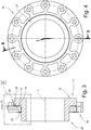
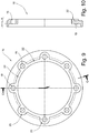
- FIG. 1 shows an end view of the flange on the side facing away from the Flanschstrom Chemistry.
- FIG. 2 shows a sectional view along section line AA in FIG. 1 ,
- the flange ring 16 initially comprises a plurality of axial bores 18 for receiving the aforementioned bolt 17. It forms an annular collar contact surface 19, which faces axially and faces the flange contact surface 13 of the annular collar 11.
- the annular collar abutment surface 19 is bounded radially outward by a support collar 20.
- This support collar 20 overlaps, such as out FIG. 6 and 7 shows, the radially outwardly facing annular collar surface 21.
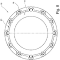
- the support collar retains the required stability despite its constructively necessary recesses in the area of the axial bores 18. This is also on FIG. 8 directed.
- the flange ring On the side facing away from the annular collar bearing surface 19, the flange ring has a radially inner reinforcing collar 22, which axially reinforces the flange ring 16 in this region.
- annular material reinforcements 23 which surround the respective axial bore 18 in full and serve the plant of the bolt heads.
- stiffening webs 24 are arranged between these reinforcements material 23 and the reinforcing collar 22. Since the flange 16 is produced in a preferred manner as a plastic injection molded part, form the stiffening webs 24 materially integral connection elements between the reinforcing collar 22 and the annular material reinforcements 23. From the sectional view of FIG.
- annular collar bearing surface 19 with respect to a vertical S, whose Reference axis represents the pipe longitudinal axis, opens radially outward.
- the annular collar contact surface 19 closes with this perpendicular S or with the Flanschstrom Chemistry 13 of the annular collar 11 an angle ⁇ , which opens starting from the cylindrical pipe section 14 of the annular collar 11 radially outward.
- the Flanschstrom requirements 13 is preferably directed vertically to the pipe section 14.
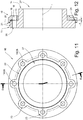
- FIG. 3 shows the flange 16 in accordance FIG. 1 , arranged on a collar 11.
- FIG. 4 shows this arrangement according to section line BB.
- the annular collar abutment surface 19 is exposed radially inwardly towards Flanschstrom Therapy 13.
- the Flanschstrom Chemistry 13 of the annular collar 11 is aligned substantially perpendicular to a tube longitudinal axis L, the annular collar abutment surface 19 of the flange 16 is issued in about by 1 to 7 degrees, in particular by 3 degrees from the vertical. Therefore, flange contact surface 13 and annular collar contact surface 19 together in an untensioned state form an angle ⁇ of 1 to 7 degrees, preferably 3 degrees, which opens radially outwards. This creates a clamping gap 25.
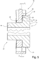
- FIG. 3 enlarged view according to FIG. 5 clarifies this situation again.
- the flange ring 16 is designed on the basis of a plate spring.
- the special, plate-spring-like geometry of the flange 16 in conjunction with its restoring elasticity to the fact that the clamping forces for producing the flange strongest act on the collar 11, where the cylindrical pipe section 14 merges into the covenant. This is at the same time that region in which an internal pipe pressure acts most strongly on the sealing gap 26 between the sealing surfaces 12 and tends to widen them wedge-shaped.
- the flange ring 16 according to the invention effectively counteracts these widening tendencies by virtue of its plate-spring-like geometry and thus creates a secure flange connection for plastic pipes and fittings.
- the clamping effect is reinforced by the support collar 20 of the flange 16. This is supported on the annular collar and thus counteracts a tilting of those areas of the flange 16, which are not supported on the annular contact surface 19 on the Flanschstrom Chemistry 13.
- the elasticity values of the flange ring 16 can be influenced by material application.
- the flange ring was provided in the exemplary embodiment with an additional stiffening collar 22 and stiffening webs 24 on its side facing away from the annular collar 11 side.
- the annular material reinforcements 23, which surround the axial bores 18, serve to reinforce the flange 16 in the region of the threaded bolts 17.
- FIGS. 9 to 12 a variant of the invention deviating in detail is shown. From the FIGS. 11 and 12 can be taken that the Vorsch healthbund 27 is provided with through holes 28.
- the axial bores 18 of the flange 16 are compared to the first embodiment - for example, shown in FIG. 1 - Located radially further inward.
- the stiffening webs 24 between the Stiffening collar 22 and the annular material reinforcements in the axial bores 18 are missing.
- the support collar 20, however, is in this embodiment, radially outward, outside of the axial bores 18. Therefore, the support collar 20 is executed here uninterrupted.
- the essential difference between the embodiments is therefore in the arrangement of the axial or through holes 18/28.
- the bolts 17 are guided in a manner not shown by the axial bores 18 of the flange 16 and the through holes 28 of the annular collars 11 and then braced against each other.
- the clamping gap 25 closes when bracing the flange 16 with the construction of a restoring force on the side of the flange.
- the support collar 20 is supported on the annular collar surface 21. In so far so far said above for the preparation of the flange.
- the flange 16 is formed as a plastic injection molded part. However, it can also be made of a suitable resilient metal. In addition, not shown in the drawing, it is conceivable to provide the flange 16 according to the invention at its annular collar contact surface with an annular bead which engages in a groove on the side of the annular collar 11, as for example EP 0 793 049 B1 or DE 10 2006 049 594 A1 to teach.
Landscapes
- Engineering & Computer Science (AREA)
- General Engineering & Computer Science (AREA)
- Mechanical Engineering (AREA)
- Flanged Joints, Insulating Joints, And Other Joints (AREA)
Description
- Die Erfindung betrifft eine Flanschverbindung für Rohrleitungen oder Armaturen aus Kunststoff, mit einem Ringbund aus Kunststoff, welcher eine axialweisende Dichtfläche und eine axialweisende Flanschanlagefläche ausbildet sowie einen zylindrischen Rohrabschnitt aufweist, mit einem Flanschring, welcher eine Vielzahl von Axialbohrungen zur Aufnahme von Schraubbolzen aufweist und eine axial weisende Ringbundanlagefläche ausbildet.
- Flanschverbindungen sind eine gängige Technik, um Armaturen oder Rohre untereinander sowie Rohre und Armaturen miteinander zu verbinden. Hierzu werden die Dichtflächen zweier Ringbunde aneinander gesetzt, ggf. unter Zwischenlage einer Dichtung. An die jeweilige Flanschanlagefläche, die auf der der Dichtfläche abgewandten Seite des Ringbundes befindlich ist, wird ein Flanschring angelegt. Beide Flanschringe werden über Schraubbolzen gegeneinander verspannt.
-
US 6,260,853 B1 zeigt eine unter anderem für Kunststoffrohe geeignete Flanschverbindung, bei welcher Flanschringe mit einem axial breiten, radial innenliegenden Abschnitt und einem axial schmalen, radial außen liegenden Abschnitt Verwendung finden. Zwischen der senkrecht zur Rohrlängsachse ausgerichteten Flanschanlagefläche des Ringbundes und der Ringbundanlagefläche des Flanschringes öffnet sich ein Winkel radial nach außen. Beim Anziehen von Befestigungsschrauben läuft zunächst der axial breite Abschnitt der Flanschringe auf den Ringbund auf und bringt so rohrnah Andruckkräfte ein. - Auf ähnliche Weise werden in den Ausführungsformen nach
Figuren 5 und6 inDE 695 32 999 T2 rohrnah erhöhte Andruckkräfte eingeleitet. Alternativ schlägt diese Veröffentlichung inFig. 2 einen Zwischenring zwischen Flanschring und Ringbund vor, welcher auch einstückig am Flanschring angeformt sein kann. Dieser Zwischenring wird rohrnah gegen den Ringbund gedrückt und leitet dort die Andruckkräfte ein. In der Ausführungsform gemäßFig 3 wird eine Federscheibe zwischen Flanschring und Ringbund gelegt, welche die Andruckkräfte im rohrnahen Bereich des Ringbundes erhöht. -
WO 93/17268 A1 - Diese Technik wird sowohl für Stahl-Ringbunde wie auch für Kunststoff-Ringbunde genutzt, wobei jedoch im Rohrleitungsbau verstärkt Kunststoffrohre und auch Kunststoffarmaturen aufgrund geringerer Korrosionsanfälligkeit Verwendung finden. Daher hat es sich in der Vergangenheit gezeigt, dass an Flanschverbindungen für Kunststoffrohre und -armaturen insbesondere dann besondere Anforderungen gestellt werden, wenn hohe Druck- und Zugspannungen auftreten. In diesem Fall neigt thermoplastischer Kunststoff zum Fließen, so dass es ungleich schwieriger ist, die vom Flansch aufgebrachten Kräfte gleichförmig über die gesamte Dichtungsbreite auf die zwischen den Ringbunden angeordnete Dichtung zu übertragen.
- Um dem besonderen Werkstoffverhalten bei Kunststoff-Flanschverbindungen Rechnung zu tragen, hat die Anmelderin mit der
EP0793049 A1 oder derDE 10 2006 049 594 A1 Flanschverbindungen geschaffen, bei denen die zueinander gewandten Flanschringe eine Art Kammer bilden, in welcher die Bunde gehalten sind. - In der
EP 0793049 A1 verzichtet die Flanschverbindung auf den bis dato üblichen, konischen Übergangsabschnitt zwischen dem zylindrischen Rohrabschnitt und dem Ringbund. Sie schafft einen Ringbund mit einer Kehlnut, in welchen der Ringwulst eines Flanschringes eingreift. Einerseits wird durch den verbesserten Ringbund die Krafteinleitung in die Flanschverbindung verbessert und diese gegen ein keilförmiges Aufspreizen des Dichtspaltes unter Innendruck weitestgehend resistent ausgeführt. Diese Wirkung wird durch das Zusammenwirken von Kehlnut und Ringwulst weiter verbessert, indem eine formschlüssige und sichere Zuordnung des Flanschringes zum Ringbund geschaffen ist. Die hierdurch entstehende Kammer hält den Kunststoff und sichert so auch eine unter hohen Innendrücken stehende Flanschverbindung. - Um Rohrinnendrücken jenseits von 16 bar sicher standzuhalten, wurde die sogenannte Kehlnutflanschverbindung durch die
DE 10 2006 049 594 A1 wesentlich verbessert. Durch eine Verbesserung der Ringbund- und Flanschgeometrien führt die unter Rohrinnendrücken jenseits von 16 bar wieder auftretende Fließbewegung des Kunststoffes zu einer Selbstkammerung, so dass eine sichere Flanschverbindung zwischen Kunststoff-Ringbunden gewährleistet ist. - Der vorzitierte Stand der Technik ist in jeder Hinsicht vorteilhaft, da er es ermöglicht, den Werkstoff Kunststoff im Rohrleitungsbau mit hohen Innendrücken zu belasten. Jedoch gibt es Situationen, in welchen die notwendige Ausgestaltung der Ringbunde mit Kehlnut und Schrägflächen nicht gewährleitstet werden kann. Deshalb ist es Aufgabe der Erfindung, eine Flanschverbindung für Rohrinnendrücke von bis zu 10 bar, bis 25 bar zu schaffen, die einerseits das Fließverhalten des Kunststoffes berücksichtigt, andererseits eine übermäßige Bearbeitung des Ringbundes überflüssig macht.
- Gelöst wird die Aufgabe von einer Flanschverbindung mit den Merkmalen des Anspruches 1, insbesondere mit den kennzeichnenden Merkmalen, wonach der Flanschring aus einem rückstellelastischen Kunststoff gebildet ist, der Flanschring nach Art einer Tellerfeder geformt ist, die Flanschanlagefläche des Ringbundes im Wesentlichen rechtwinklig zur Rohrlängsachse ausgerichtet ist und die Ringbundanlagefläche des Flanschringes mit der Flanschanlagefläche des Ringbundes einen Winkel einschließt, der sich ausgehend vom zylindrischen Rohrabschnitt des Ringbundes radial nach außen öffnet.
- Beim Verspannen der Flanschringe gegeneinander laufen zuerst die rohrabschnittsnahen Bereiche des Flanschrings auf die Flanschanlagefläche des Ringbundes auf. Mit fortgesetztem Anziehen der Schraubbolzen vergrößert sich die gegenseitige Anlagefläche zwischen Ringbund und Flanschring. Durch die gegenüber der Ringbundanlagefläche geneigte Ausbildung der Ringbundanlagefläche wird eine erhöht Anpresskraft im Bereich des zylindrischen Rohrabschnitts auf die Ringbundanlagefläche aufgebraucht und wirkt der dort vorhandenen Tendenz zum keilförmigen Aufweiten unter Rohrinnendruck entgegen.
- Der Flanschring ist aus einem rückstellelastischen Material, nämlich aus einem speziellen Kunststoff gefertigt. Aufgrund der Rückstellelastizität wirkt der Flanschring auf den Ringbund nach Art einer Tellerfeder und drängt - wie eben vorbeschrieben - die Ringbunde im Bereich des Übergangs hin zum zylindrischen Rohrabschnitt mit einer höheren Anpresskraft gegeneinander. Die Rückstellelastizität verhindert jedoch eine plastische Verformung des Flanschringes, so dass die vorteilhafte Wirkung auch aufrechterhalten bleibt, wenn hohe Anzugsmomente auf die Schraubbolzen wirken.
- Die
EP 0 840 049 A2 offenbart eine der Lehre der Erfindung konträre Lösung, die lediglich den Anschein einer gleichartigen Ausgestaltung erweckt. Die dortige, primär für PVC-Rohrverbindungen zu nutzende Flanschverbindung zeigt einen Ringbund, dessen Flanschanlagefläche aus der senkrechten in Richtung Dichtfläche ausgestellt ist. Der Flanschring kann bei zu hoher Belastung in Richtung Flanschanlagefläche des Ringbundes verkippen, wodurch die rohrnahen Bereiche des Ringbundes zum Schutz vor Beschädigung entlastet werden. Die Lösung derEP 0 840 049 A2 entlastet demzufolge gerade die Bereiche des Ringbundes, die mit den Mitteln der Erfindung mit einer erhöhten Anpresskraft beaufschlagt werden. -
WO 2006/045887 A1 offenbart eine Flanschverbindung, bei welcher die Flanschringe aus mehreren, axial hintereinander angeordneten Ringsegmenten gebildet sind. Dies erlaubt ein Verkippen der einzelnen Segmente, so dass sich die Flanschringe an eine Neigung der Ringbunde anpassen können. Die dort im Bereich der Verschraubungen angeordneten Elastomerelemente dienen als Montagehilfe und sind aufgrund Ihrer Anordnung und Ausgestaltung nicht in der Lage, rohrnah erhöhte Andruckkräfte auf den Ringbund aufzubringen. - Es hat sich herausgestellt, dass die vorteilhafte Wirkung des erfindungsgemäßen Flanschringes am stärksten ist, wenn der Winkel zwischen Flanschanlagefläche und einer vertikal zum Rohrabschnitt gerichteten Ringbundanlagefläche zwischen 1 Grad und 7 Grad, insbesondere zwischen 1 Grad und 5 Grad, bevorzugt 3 Grad beträgt.
- Es ist ferner vorgesehen, dass der Flanschring an seiner Ringbundanlagenfläche einen den Ringbund außenumfänglich übergreifenden, axial weisenden Kragen ausbildet, wobei im Zweifelsfall vorgesehen ist, der axial weisende Kragen Ausnehmungen aufweist, die mit den Axialbohrungen zur Aufnahme von Schraubbolzen fluchten.
- Der axialweisende Kragen, welcher den Ringbund außenumfänglich übergreift, stützt den Flanschring beim Herstellen der Flanschverbindung am Ringbund ab. Insbesondere bei Flanschverbindungen, bei welchen die Schraubbolzen den Ringbund radial außen übergreifen hilft dies, die rohrabschnittsnah einzubringende höhere Kraft aufrechtzuerhalten, indem ein übermäßiges Verkippen des Flanschringes vermieden wird.
- Schließlich ist vorgesehen, dass der Flanschring auf seiner dem Ringbund abgewandten Seite einen axial weisenden, insbesondere innenumfänglich angeordneten Versteifungs-Kragen aufweist, der insbesondere zur Anlage am zylindrischen Rohrstück vorgesehenen ist. Über diesen Kragen kann die Steifheit eines rückstellelastisch ausgebildeten Flanschringes verstärkt werden, so dass größere Kräfte rohrabschnittsnah in den Ringbund eingeleitet werden können.
- Vorgesehen ist ferner, dass der Flanschring auf seiner dem Ringbund abgewandten Seite ringförmige Materialverstärkungen aufweist, die jede Axialbohrung umgeben.
- Weitere Vorteile der Erfindung sowie ein besseres Verständnis derselben folgt aus dem nun beschriebenen Ausführungsbeispiel. Es zeigen:
- Figur 1
- eine Aufsicht auf einen Flanschring einer erfindungsgemäßen Flanschverbindung auf die dem Ringbund abgewandte Seite,
- Figur 2
- eine Schnittansicht durch den Flanschring gemäß
Figur 1 entsprechend Schnittlinie A-A, - Figur 3
- eine Schnittansicht der Anordnung gemäß
Figur 4 entsprechend Schnittlinie B-B, - Figur 4
- eine Ansicht auf den Flanschring gemäß
Figur 1 nebst Vorschweißbund, - Figur 5
- eine vergrößerte Darstellung gemäß
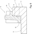
Figur 3 , - Figur 6
- eine vergrößerte Teildarstellung gemäß Ausschnittskreis VI in
Figur 3 mit Flanschring in verspanntem Zustand, - Figur 7
- eine erfindungsgemäße Flanschverbindung zweier Rohrstücke,
- Figur 8
- eine Ansicht auf die Ringbundanlagefläche des Flanschringes gemäß
Figur 1 , - Figur 9
- eine Ansicht auf die dem Ringbund abgewandte Fläche einer zweiten Ausführungsform eines Flanschringes der erfindungsgemäßen Flanschverbindung,
- Figur 10
- eine Schnittdarstellung des Flanschringes gemäß Schnittlinie C-C in
Figur 9 , - Figur 11
- die Ansicht auf den Flanschring entsprechend
Figur 9 , jedoch mit Darstellung eines Vorschweißbundes, - Figur 12
- eine Schnittdarstellung gemäß Schnittlinie D-D in
Figur 11 . - In den Figuren ist eine erfindungsgemäße Flanschverbindung insgesamt mit der Bezugsziffer 10 versehen. Sie ist in ihrer Gesamtheit beispielsweise in
Figur 7 dargestellt. Sie umfasst zwei Ringbunde 11 aus Kunststoff, die beispielsweise als Vorschweißbunde 27 für Kunststoffrohre oder Kunststoffarmaturen ausgebildet sein können. Diese Ringbunde verfügen jeweils verfügen über eine axialweisende Dichtfläche 12 sowie eine der jeweiligen Dichtfläche 12 abgewandte, ebenfalls axialweisende Flanschanlagefläche 13. Ein zylindrischer Rohrabschnitt 14 erstreckt sich in die der jeweiligen Dichtfläche 12 entgegengesetzte Richtung, um mit einem Kunststoffrohr oder einer Kunststoffarmatur verbunden zu werden. Zwischen den einander zugewandten Dichtflächen 12 der beiden inFigur 7 dargestellten Ringbunde 11 ist eine Dichtung 15 angeordnet, die einen Fluidaustritt entlang der gegenseitigen Anlagefläche der Ringbunde 11 verhindert. - Jeder Ringbund 11 trägt ein Losflansch in Form eines Flanschringes 16. Zur Herstellung der Flanschverbindung werden die Flanschringe über Schraubbolzen 17 gegeneinander verspannt.
- Der Flanschring 16 ist zunächst in den
Figuren 1 und 2 gezeigt.Figur 1 zeigt eine Stirnansicht des Flanschringes auf die der Flanschanlagefläche abgewandte Seite.Figur 2 zeigt eine Schnittansicht gemäß Schnittlinie A-A inFigur 1 . - Der Flanschring 16 umfasst zunächst eine Vielzahl von Axialbohrungen 18 zur Aufnahme der vorwähnten Schraubbolzen 17. Er bildet eine Ringbundanlagefläche 19 aus, die axial weist und der Flanschanlagefläche 13 des Ringbunds 11 zugewandt ist. Die Ringbundanlagefläche 19 wird radial nach außen durch einen Stützkragen 20 begrenzt. Dieser Stützkragen 20 überfängt, wie beispielsweise aus
Figur 6 und7 hervorgeht, die radial nach außen weisende Ringbund-Mantelfläche 21. Im Bereich der Axialbohrungen 18 ist der Stützkragen 20 unterbrochen und torbogenartig um die Axialbohrungen 18 herumgeführt. Auf die Weise behält der Stützkragen trotz seiner im Bereich der Axialbohrungen 18 konstruktiv notwendigen Ausnehmungen die erforderliche Stabilität. Hierzu wird auch aufFigur 8 verwiesen. - Auf der der Ringbundanlagefläche 19 abgewandten Seite weist der Flanschring einen radial innenliegenden Versteifungskragen 22 auf, der in diesem Bereich den Flanschring 16 axial verstärkt. Im Bereich der Axialbohrungen 18 ist der Flanschring 16 auf seiner dem Ringbund 11 abgewandten Seite mit ringförmigen Materialverstärkungen 23 versehen, die die jeweilige Axialbohrung 18 vollumfänglich umgeben und der Anlage der Schraubbolzen-Köpfe dienen. Zwischen diesen Materialverstärkungen 23 und dem Versteifungskragen 22 sind Versteifungsstege 24 angeordnet. Da der Flanschring 16 in bevorzugter Weise als Kunststoffspritzgießteil hergestellt ist, bilden die Versteifungsstege 24 werkstoffeinheitlich stoffschlüssige Verbindungselemente zwischen dem Versteifungskragen 22 und dem ringförmigen Materialverstärkungen 23. Aus der Schnittdarstellung der
Figur 2 ist ersichtlich, dass die Ringbundanlagefläche 19 gegenüber einer Senkrechten S, deren Bezugsachse die Rohrlängsachse darstellt, sich radial nach außen öffnet. Die Ringbundanlagefläche 19 schließt mit dieser Senkrechten S bzw. mit der Flanschanlagefläche 13 des Ringbundes 11 einen Winkel α ein, der sich ausgehend vom zylindrischen Rohrabschnitt 14 des Ringbundes 11 radial nach außen öffnet. Die Flanschanlagefläche 13 ist bevorzugt vertikal zum Rohrabschnitt 14 gerichtet. -
Figur 3 zeigt den Flanschring 16 gemäßFigur 1 , angeordnet auf einem Ringbund 11.Figur 4 zeigt diese Anordnung gemäß Schnittlinie B-B. - Wie der Schnittdarstellung nach
Figur 3 zu entnehmen ist, ist die Ringbundanlagefläche 19 radial innen in Richtung Flanschanlagefläche 13 ausgestellt. Die Flanschanlagefläche 13 des Ringbundes 11 ist im Wesentlichen rechtwinklig zu einer Rohrlängsachse L ausgerichtet, die Ringbundanlagefläche 19 des Flanschringes 16 ist in um etwa 1 bis 7 Grad, insbesondere um 3 Grad aus der Lotrechten ausgestellt. Deshalb schließen Flanschanlagefläche 13 und Ringbundanlagefläche 19 miteinander in ungespanntem Zustand einen Winkel α von 1 bis 7 Grad, bevorzugt von 3 Grad miteinander ein, der sich radial nach außen öffnet. Hierdurch entsteht ein Spannspalt 25. - Die gegenüber
Figur 3 vergrößerte Darstellung gemäßFigur 5 verdeutlicht diesen Sachverhalt nochmals. Darüber hinaus zeigen dieFiguren 4 und5 , dass der Stützkragen 20 die radial weisende Umfangsfläche 21 des Ringbundes 11 überfängt und sich dort abstützt. DerFigur 5 ist darüber hinaus am ehesten zu entnehmen, dass der Flanschring 16 in Anlehnung an eine Tellerfeder ausgebildet ist. - Wird nunmehr durch anziehen der Schraubbolzen 17 die Flanschverbindung gemäß
Figur 7 hergestellt, wird der Flanschring 16 rückstellelastisch verformt. Über die Spannkräfte wird die Ringbundanlagefläche 19 vollflächig gegen die Flanschanlagefläche 13 gezogen, so dass sich der Spannspalt 25 schließt. - Die spezielle, tellerfederartige Geometrie des Flanschringes 16 führt in Zusammenspiel mit seiner Rückstellelastizität dazu, dass die Spannkräfte zur Herstellung der Flanschverbindung am stärksten auf den Ringbund 11 wirken, wo der zylindrische Rohrabschnitt 14 in den Bund übergeht. Dies ist gleichzeitig derjenige Bereich, in welchem ein Rohrinnendruck am stärksten auf den Dichtspalt 26 zwischen den Dichtflächen 12 wirkt und diesen tendenziell keilförmig aufweitet. Der erfindungsgemäße Flanschring 16 wirkt durch seine tellerfederartige Geometrie diesen Aufweitungstendenzen wirksam entgegen und schafft so eine sichere Flanschverbindung für Kunststoff-Rohre und -armaturen.
- In dem dargestellten Ausführungsbeispiel wird die Spannwirkung durch den Stützkragen 20 des Flanschrings 16 verstärkt. Dieser stützt sich auf dem Ringbund ab und wirkt so einem Verkippen derjenigen Bereiche des Flanschringes 16 entgegen, die nicht über die Ringbundanlagefläche 19 an der Flanschanlagefläche 13 abgestützt sind. Die Elastizitätswerte des Flanschringes 16 lassen sich durch Materialauftrag beeinflussen. Hierzu wurde der Flanschring im Ausführungsbeispiel mit einem zusätzlichen Versteifungskragen 22 sowie Versteifungsstegen 24 auf seiner dem Ringbund 11 abgewandten Seite versehen. Die ringförmigen Materialverstärkungen 23, die die Axialbohrungen 18 umschließen, dienen der Verstärkung des Flanschringes 16 im Bereich der Schraubbolzen 17.
- In den
Figuren 9 bis 12 ist eine im Detail abweichende Ausführungsform der Erfindung dargestellt. Aus denFiguren 11 und 12 ist entnehmbar, dass der Vorschweißbund 27 mit Durchgangsbohrungen 28 versehen ist. Die Axialbohrungen 18 des Flanschringes 16 sind gegenüber des ersten Ausführungsbeispiels - beispielsweise dargestellt inFigur 1 - radial weiter innen liegend angeordnet. Die Versteifungsstege 24 zwischen dem Versteifungskragen 22 und den ringförmigen Materialverstärkungen im Bereich der Axialbohrungen 18 fehlen. Der Stützkragen 20 hingegen befindet sich bei diesem Ausführungsbeispiel radial außen, außerhalb der Axialbohrungen 18. Deshalb ist der Stützkragen 20 hier ununterbrochen ausgeführt. - Der wesentliche Unterschied zwischen den Ausführungsbeispielen liegt demnach in der Anordnung der Axial- bzw. Durchgangsbohrungen 18/28. Bei diesem zweiten Ausführungsbeispiel werden die Schraubbolzen 17 in nicht dargestellter Weise durch die Axialbohrungen 18 der Flanschringe 16 und die Durchgangsbohrungen 28 der Ringbunde 11 geführt und dann gegeneinander verspannt. Wie vorbeschrieben, schließt sich der Spannspalt 25 beim Verspannen der Flanschringen 16 unter Aufbau einer Rückstellkraft auf Seiten des Flanschringes. Der Stützkragen 20 stützt sich an der Ringbundmantelfläche 21 ab. In so weit gilt also das oben zur Herstellung der Flanschverbindung Gesagte.
- In bevorzugter Ausführungsform ist der Flanschring 16 als Kunststoffspritzgießteil gebildet. Er kann jedoch auch aus einem geeigneten rückstellelastischen Metall gefertigt sein. Ergänzend, zeichnerisch nicht dargestellt, ist es denkbar, den erfindungsgemäßen Flanschring 16 an seiner Ringbundanlagefläche mit einem Ringwulst zu versehen, der in eine Kehlnut auf Seiten des Ringbundes 11 eingreift, wie es beispielsweise
EP 0 793 049 B1 oderDE 10 2006 049 594 A1 lehren. -
- 10
- Flanschverbindung
- 11
- Ringbund
- 12
- Dichtfläche
- 13
- Flanschanlagefläche
- 14
- zylindrischer Rohrabschnitt
- 15
- Dichtung
- 16
- Flanschring
- 17
- Schraubbolzen
- 18
- Axialbohrung
- 19
- Ringbundanlagefläche
- 20
- Stützkragen
- 21
- Ringbund-Mantelfläche
- 22
- Versteifungskragen
- 23
- ringförmige Materialverstärkung
- 24
- Versteifungssteg
- 25
- Spannspalt
- 26
- Dichtspalt
- 27
- Vorschweißbund
- 28
- Durchgangsbohrung
Claims (6)
- Flanschverbindung (10) für Rohrleitungen oder Armaturen aus Kunststoff,- mit einem Ringbund (11) aus Kunststoff, welcher eine axialweisende Dichtfläche (12) und eine axialweisende Flanschanlagefläche (13) ausbildet sowie einen zylindrischen Rohrabschnitt (14) aufweist,- mit einem Flanschring (16), welcher eine Vielzahl von Axialbohrungen (18) zur Aufnahme von Schraubbolzen (17) aufweist und eine axial weisende Ringbundanlagefläche (19) ausbildetdadurch gekennzeichnet, dass- der Flanschring (16) aus einem rückstellelastischen Kunststoff gebildet ist,- der Flanschring (16) nach Art einer Tellerfeder geformt ist,- die Flanschanlagefläche (13) des Ringbundes (11) im Wesentlichen rechtwinklig zur Rohrlängsachse (L) ausgerichtet ist,- die Ringbundanlagefläche (19) des Flanschringes (16) mit der Flanschanlagefläche (13) des Ringbundes (11) einen Winkel (α) einschließt, der sich ausgehend vom zylindrischen Rohrabschnitt (14) des Ringbundes (11) radial nach außen öffnet.
- Flanschverbindung (10) nach Anspruch 1, dadurch gekennzeichnet, dass der Flanschring (16) an seiner Ringbundanlagenfläche (19) einen den Ringbund (11) außenumfänglich übergreifenden, axial weisenden Stützkragen (20) ausbildet.
- Flanschverbindung (10) nach Anspruch 2, dadurch gekennzeichnet, dass der axial weisende Stützkragen (20) Ausnehmungen aufweist, die mit den Axialbohrungen (18) zur Aufnahme von Schraubbolzen (17) fluchten.
- Flanschverbindung (10) nach einem der Ansprüche 1 bis 3, dadurch gekennzeichnet, dass der Flanschring (16) auf seiner dem Ringbund (11) abgewandten Seite einen axial weisenden, innenumfänglich angeordneten Versteifungskragen (22) aufweist.
- Flanschverbindung (10) nach einem der Ansprüche 1 bis 4, dadurch gekennzeichnet, dass der Flanschring (16) auf seiner dem Ringbund (11) abgewandten Seite ringförmige Materialverstärkungen aufweist, die jede Axialbohrung (18) umgeben.
- Flanschverbindung (10) nach einem der vorhergehenden Ansprüche, dadurch gekennzeichnet, dass der Winkel zwischen Flanschanlagefläche (13) und Ringbundanlagefläche (19) zwischen 1 Grad und 7 Grad, insbesondere zwischen 1 Grad und 5 Grad, bevorzugt 3 Grad beträgt.
Applications Claiming Priority (1)
| Application Number | Priority Date | Filing Date | Title |
|---|---|---|---|
| DE102015104718.7A DE102015104718A1 (de) | 2015-03-27 | 2015-03-27 | Flanschverbindung |
Publications (2)
| Publication Number | Publication Date |
|---|---|
| EP3073166A1 EP3073166A1 (de) | 2016-09-28 |
| EP3073166B1 true EP3073166B1 (de) | 2017-05-17 |
Family
ID=55405254
Family Applications (1)
| Application Number | Title | Priority Date | Filing Date |
|---|---|---|---|
| EP16156810.0A Active EP3073166B1 (de) | 2015-03-27 | 2016-02-23 | Flanschverbindung |
Country Status (2)
| Country | Link |
|---|---|
| EP (1) | EP3073166B1 (de) |
| DE (1) | DE102015104718A1 (de) |
Cited By (1)
| Publication number | Priority date | Publication date | Assignee | Title |
|---|---|---|---|---|
| US11060641B2 (en) * | 2015-12-01 | 2021-07-13 | Minimax Gmbh & Co. Kg | Method for producing a flange blank and for producing a flange |
Families Citing this family (3)
| Publication number | Priority date | Publication date | Assignee | Title |
|---|---|---|---|---|
| DE102019100897A1 (de) | 2019-01-15 | 2020-07-16 | Reinert - Ritz Gmbh | Pass- und Ausbaustück für Rohrleitungen |
| JP7413006B2 (ja) * | 2019-12-24 | 2024-01-15 | 株式会社クボタケミックス | 合成樹脂フランジ管継手 |
| JP7288423B2 (ja) * | 2020-03-30 | 2023-06-07 | 積水化学工業株式会社 | 管継手 |
Family Cites Families (9)
| Publication number | Priority date | Publication date | Assignee | Title |
|---|---|---|---|---|
| NO177160C (no) * | 1992-02-20 | 1995-07-26 | Steelproducts Offshore As | Kobling omfattende to motstående koblingshalvdeler |
| US5716083A (en) * | 1994-11-25 | 1998-02-10 | Kc Multi-Ring Products, Inc. | Joint assembly and backing mechanism therefor |
| DE19607898A1 (de) | 1996-03-01 | 1997-09-04 | Ritz Reinert Gmbh | Flanschverbindung für Rohrleitungen, Behälter, Apparate o. dgl. aus Kunststoff |
| DE19725105A1 (de) * | 1996-11-01 | 1998-05-14 | Fischer Georg Rohrleitung | Bundbuchse |
| US6260853B1 (en) * | 1998-06-23 | 2001-07-17 | Kc Multi-Ring Products, Inc. | Gasket having centering features |
| DE29910323U1 (de) * | 1999-06-14 | 1999-08-26 | Kremo Werke Hermanns GmbH & Co KG, 47798 Krefeld | Rohr, insbesondere Kunststoffrohr |
| FI118095B (fi) * | 2004-10-29 | 2007-06-29 | Maricap Oy | Putkiliitos |
| DE102006049594A1 (de) | 2006-10-20 | 2008-04-24 | Reinert-Ritz Gmbh | Flanschverbindung für Rohrleitungen |
| ATE498089T1 (de) * | 2008-12-02 | 2011-02-15 | Ritz Reinert Gmbh | Flanschverbindungen für rohrleitungen |
-
2015
- 2015-03-27 DE DE102015104718.7A patent/DE102015104718A1/de not_active Withdrawn
-
2016
- 2016-02-23 EP EP16156810.0A patent/EP3073166B1/de active Active
Cited By (1)
| Publication number | Priority date | Publication date | Assignee | Title |
|---|---|---|---|---|
| US11060641B2 (en) * | 2015-12-01 | 2021-07-13 | Minimax Gmbh & Co. Kg | Method for producing a flange blank and for producing a flange |
Also Published As
| Publication number | Publication date |
|---|---|
| DE102015104718A1 (de) | 2016-09-29 |
| EP3073166A1 (de) | 2016-09-28 |
Similar Documents
| Publication | Publication Date | Title |
|---|---|---|
| DE10119534B4 (de) | Metallische Dichtung | |
| EP2394087B1 (de) | Fitting für dickwandige rohre und verfahren zu dessen herstellung | |
| EP0186727B2 (de) | Rohrverbindung | |
| DE2004046C2 (de) | Dichtung | |
| DE69826192T2 (de) | Vorrichtung zum Verbinden von zwei Rohrstücken und Anwendung der Verbindung von Rohrstücken | |
| DE3317061C2 (de) | Flanschverbindungsanordnung | |
| EP1914465B1 (de) | Flanschverbindung für Rohrleitungen | |
| DE1475688A1 (de) | Klemmvorrichtung,insbesondere fuer Rohrleitungen | |
| EP3073166B1 (de) | Flanschverbindung | |
| EP2330326B1 (de) | Rohrförmiges Bauteil | |
| DE102021115904A1 (de) | Flanschverbindungsanordnung für eine rohrleitung | |
| EP4115107B1 (de) | Rohrverbindung | |
| DE3636773C2 (de) | ||
| EP1965117A1 (de) | Flanschverbindungen | |
| EP3601865B1 (de) | Rohrkupplung | |
| EP2673540B1 (de) | Anordnung mit einem flansch | |
| DE202015101565U1 (de) | Flanschverbindung | |
| DE20121354U1 (de) | Anschlusselement | |
| EP0940618B1 (de) | Spannbare Rohrkupplung | |
| EP3321545B1 (de) | Dichtungsprofil, und damit ausgestattete dichtungsanordnung | |
| DE102016211816B4 (de) | Gleitringdichtungsanordnung mit beschichteter Balgeinheit | |
| DE202012101483U1 (de) | Dichtung für eine Flanschverbindung | |
| EP3859194B1 (de) | Dichtelement für eine kühlmittelverbindung zwischen zwei werkzeugbauteilen eines werkzeugs und verfahren zur instandhaltung dieses werkezeugs | |
| DE202020106261U1 (de) | Anschlussstutzen für Wellrohre | |
| DE3540321C2 (de) |
Legal Events
| Date | Code | Title | Description |
|---|---|---|---|
| PUAI | Public reference made under article 153(3) epc to a published international application that has entered the european phase |
Free format text: ORIGINAL CODE: 0009012 |
|
| AK | Designated contracting states |
Kind code of ref document: A1 Designated state(s): AL AT BE BG CH CY CZ DE DK EE ES FI FR GB GR HR HU IE IS IT LI LT LU LV MC MK MT NL NO PL PT RO RS SE SI SK SM TR |
|
| AX | Request for extension of the european patent |
Extension state: BA ME |
|
| 17P | Request for examination filed |
Effective date: 20160907 |
|
| RBV | Designated contracting states (corrected) |
Designated state(s): AL AT BE BG CH CY CZ DE DK EE ES FI FR GB GR HR HU IE IS IT LI LT LU LV MC MK MT NL NO PL PT RO RS SE SI SK SM TR |
|
| GRAP | Despatch of communication of intention to grant a patent |
Free format text: ORIGINAL CODE: EPIDOSNIGR1 |
|
| STAA | Information on the status of an ep patent application or granted ep patent |
Free format text: STATUS: GRANT OF PATENT IS INTENDED |
|
| INTG | Intention to grant announced |
Effective date: 20161221 |
|
| GRAS | Grant fee paid |
Free format text: ORIGINAL CODE: EPIDOSNIGR3 |
|
| GRAA | (expected) grant |
Free format text: ORIGINAL CODE: 0009210 |
|
| STAA | Information on the status of an ep patent application or granted ep patent |
Free format text: STATUS: THE PATENT HAS BEEN GRANTED |
|
| AK | Designated contracting states |
Kind code of ref document: B1 Designated state(s): AL AT BE BG CH CY CZ DE DK EE ES FI FR GB GR HR HU IE IS IT LI LT LU LV MC MK MT NL NO PL PT RO RS SE SI SK SM TR |
|
| REG | Reference to a national code |
Ref country code: GB Ref legal event code: FG4D Free format text: NOT ENGLISH |
|
| REG | Reference to a national code |
Ref country code: CH Ref legal event code: EP |
|
| REG | Reference to a national code |
Ref country code: IE Ref legal event code: FG4D Free format text: LANGUAGE OF EP DOCUMENT: GERMAN |
|
| REG | Reference to a national code |
Ref country code: CH Ref legal event code: NV Representative=s name: SCHMAUDER AND PARTNER AG PATENT- UND MARKENANW, CH Ref country code: AT Ref legal event code: REF Ref document number: 894782 Country of ref document: AT Kind code of ref document: T Effective date: 20170615 |
|
| REG | Reference to a national code |
Ref country code: DE Ref legal event code: R096 Ref document number: 502016000023 Country of ref document: DE |
|
| REG | Reference to a national code |
Ref country code: SE Ref legal event code: TRGR |
|
| REG | Reference to a national code |
Ref country code: NL Ref legal event code: MP Effective date: 20170517 |
|
| REG | Reference to a national code |
Ref country code: NO Ref legal event code: T2 Effective date: 20170517 |
|
| REG | Reference to a national code |
Ref country code: LT Ref legal event code: MG4D |
|
| PG25 | Lapsed in a contracting state [announced via postgrant information from national office to epo] |
Ref country code: FI Free format text: LAPSE BECAUSE OF FAILURE TO SUBMIT A TRANSLATION OF THE DESCRIPTION OR TO PAY THE FEE WITHIN THE PRESCRIBED TIME-LIMIT Effective date: 20170517 Ref country code: ES Free format text: LAPSE BECAUSE OF FAILURE TO SUBMIT A TRANSLATION OF THE DESCRIPTION OR TO PAY THE FEE WITHIN THE PRESCRIBED TIME-LIMIT Effective date: 20170517 Ref country code: LT Free format text: LAPSE BECAUSE OF FAILURE TO SUBMIT A TRANSLATION OF THE DESCRIPTION OR TO PAY THE FEE WITHIN THE PRESCRIBED TIME-LIMIT Effective date: 20170517 Ref country code: HR Free format text: LAPSE BECAUSE OF FAILURE TO SUBMIT A TRANSLATION OF THE DESCRIPTION OR TO PAY THE FEE WITHIN THE PRESCRIBED TIME-LIMIT Effective date: 20170517 Ref country code: GR Free format text: LAPSE BECAUSE OF FAILURE TO SUBMIT A TRANSLATION OF THE DESCRIPTION OR TO PAY THE FEE WITHIN THE PRESCRIBED TIME-LIMIT Effective date: 20170818 |
|
| PG25 | Lapsed in a contracting state [announced via postgrant information from national office to epo] |
Ref country code: LV Free format text: LAPSE BECAUSE OF FAILURE TO SUBMIT A TRANSLATION OF THE DESCRIPTION OR TO PAY THE FEE WITHIN THE PRESCRIBED TIME-LIMIT Effective date: 20170517 Ref country code: IS Free format text: LAPSE BECAUSE OF FAILURE TO SUBMIT A TRANSLATION OF THE DESCRIPTION OR TO PAY THE FEE WITHIN THE PRESCRIBED TIME-LIMIT Effective date: 20170917 Ref country code: PL Free format text: LAPSE BECAUSE OF FAILURE TO SUBMIT A TRANSLATION OF THE DESCRIPTION OR TO PAY THE FEE WITHIN THE PRESCRIBED TIME-LIMIT Effective date: 20170517 Ref country code: RS Free format text: LAPSE BECAUSE OF FAILURE TO SUBMIT A TRANSLATION OF THE DESCRIPTION OR TO PAY THE FEE WITHIN THE PRESCRIBED TIME-LIMIT Effective date: 20170517 Ref country code: NL Free format text: LAPSE BECAUSE OF FAILURE TO SUBMIT A TRANSLATION OF THE DESCRIPTION OR TO PAY THE FEE WITHIN THE PRESCRIBED TIME-LIMIT Effective date: 20170517 Ref country code: BG Free format text: LAPSE BECAUSE OF FAILURE TO SUBMIT A TRANSLATION OF THE DESCRIPTION OR TO PAY THE FEE WITHIN THE PRESCRIBED TIME-LIMIT Effective date: 20170817 |
|
| PG25 | Lapsed in a contracting state [announced via postgrant information from national office to epo] |
Ref country code: DK Free format text: LAPSE BECAUSE OF FAILURE TO SUBMIT A TRANSLATION OF THE DESCRIPTION OR TO PAY THE FEE WITHIN THE PRESCRIBED TIME-LIMIT Effective date: 20170517 Ref country code: RO Free format text: LAPSE BECAUSE OF FAILURE TO SUBMIT A TRANSLATION OF THE DESCRIPTION OR TO PAY THE FEE WITHIN THE PRESCRIBED TIME-LIMIT Effective date: 20170517 Ref country code: CZ Free format text: LAPSE BECAUSE OF FAILURE TO SUBMIT A TRANSLATION OF THE DESCRIPTION OR TO PAY THE FEE WITHIN THE PRESCRIBED TIME-LIMIT Effective date: 20170517 Ref country code: EE Free format text: LAPSE BECAUSE OF FAILURE TO SUBMIT A TRANSLATION OF THE DESCRIPTION OR TO PAY THE FEE WITHIN THE PRESCRIBED TIME-LIMIT Effective date: 20170517 Ref country code: SK Free format text: LAPSE BECAUSE OF FAILURE TO SUBMIT A TRANSLATION OF THE DESCRIPTION OR TO PAY THE FEE WITHIN THE PRESCRIBED TIME-LIMIT Effective date: 20170517 |
|
| REG | Reference to a national code |
Ref country code: DE Ref legal event code: R097 Ref document number: 502016000023 Country of ref document: DE |
|
| PG25 | Lapsed in a contracting state [announced via postgrant information from national office to epo] |
Ref country code: IT Free format text: LAPSE BECAUSE OF FAILURE TO SUBMIT A TRANSLATION OF THE DESCRIPTION OR TO PAY THE FEE WITHIN THE PRESCRIBED TIME-LIMIT Effective date: 20170517 Ref country code: SM Free format text: LAPSE BECAUSE OF FAILURE TO SUBMIT A TRANSLATION OF THE DESCRIPTION OR TO PAY THE FEE WITHIN THE PRESCRIBED TIME-LIMIT Effective date: 20170517 |
|
| PLBE | No opposition filed within time limit |
Free format text: ORIGINAL CODE: 0009261 |
|
| STAA | Information on the status of an ep patent application or granted ep patent |
Free format text: STATUS: NO OPPOSITION FILED WITHIN TIME LIMIT |
|
| 26N | No opposition filed |
Effective date: 20180220 |
|
| PG25 | Lapsed in a contracting state [announced via postgrant information from national office to epo] |
Ref country code: MT Free format text: LAPSE BECAUSE OF FAILURE TO SUBMIT A TRANSLATION OF THE DESCRIPTION OR TO PAY THE FEE WITHIN THE PRESCRIBED TIME-LIMIT Effective date: 20170517 Ref country code: MC Free format text: LAPSE BECAUSE OF FAILURE TO SUBMIT A TRANSLATION OF THE DESCRIPTION OR TO PAY THE FEE WITHIN THE PRESCRIBED TIME-LIMIT Effective date: 20170517 |
|
| REG | Reference to a national code |
Ref country code: IE Ref legal event code: MM4A |
|
| REG | Reference to a national code |
Ref country code: BE Ref legal event code: MM Effective date: 20180228 |
|
| PG25 | Lapsed in a contracting state [announced via postgrant information from national office to epo] |
Ref country code: LU Free format text: LAPSE BECAUSE OF NON-PAYMENT OF DUE FEES Effective date: 20180223 |
|
| REG | Reference to a national code |
Ref country code: FR Ref legal event code: ST Effective date: 20181031 |
|
| PG25 | Lapsed in a contracting state [announced via postgrant information from national office to epo] |
Ref country code: IE Free format text: LAPSE BECAUSE OF NON-PAYMENT OF DUE FEES Effective date: 20180223 |
|
| PG25 | Lapsed in a contracting state [announced via postgrant information from national office to epo] |
Ref country code: FR Free format text: LAPSE BECAUSE OF NON-PAYMENT OF DUE FEES Effective date: 20180228 Ref country code: BE Free format text: LAPSE BECAUSE OF NON-PAYMENT OF DUE FEES Effective date: 20180228 |
|
| PG25 | Lapsed in a contracting state [announced via postgrant information from national office to epo] |
Ref country code: TR Free format text: LAPSE BECAUSE OF FAILURE TO SUBMIT A TRANSLATION OF THE DESCRIPTION OR TO PAY THE FEE WITHIN THE PRESCRIBED TIME-LIMIT Effective date: 20170517 |
|
| PG25 | Lapsed in a contracting state [announced via postgrant information from national office to epo] |
Ref country code: PT Free format text: LAPSE BECAUSE OF FAILURE TO SUBMIT A TRANSLATION OF THE DESCRIPTION OR TO PAY THE FEE WITHIN THE PRESCRIBED TIME-LIMIT Effective date: 20170517 |
|
| PG25 | Lapsed in a contracting state [announced via postgrant information from national office to epo] |
Ref country code: HU Free format text: LAPSE BECAUSE OF FAILURE TO SUBMIT A TRANSLATION OF THE DESCRIPTION OR TO PAY THE FEE WITHIN THE PRESCRIBED TIME-LIMIT; INVALID AB INITIO Effective date: 20160223 Ref country code: CY Free format text: LAPSE BECAUSE OF FAILURE TO SUBMIT A TRANSLATION OF THE DESCRIPTION OR TO PAY THE FEE WITHIN THE PRESCRIBED TIME-LIMIT Effective date: 20170517 Ref country code: MK Free format text: LAPSE BECAUSE OF NON-PAYMENT OF DUE FEES Effective date: 20170517 |
|
| PG25 | Lapsed in a contracting state [announced via postgrant information from national office to epo] |
Ref country code: AL Free format text: LAPSE BECAUSE OF FAILURE TO SUBMIT A TRANSLATION OF THE DESCRIPTION OR TO PAY THE FEE WITHIN THE PRESCRIBED TIME-LIMIT Effective date: 20170517 |
|
| GBPC | Gb: european patent ceased through non-payment of renewal fee |
Effective date: 20200223 |
|
| PG25 | Lapsed in a contracting state [announced via postgrant information from national office to epo] |
Ref country code: SI Free format text: LAPSE BECAUSE OF NON-PAYMENT OF DUE FEES Effective date: 20180223 |
|
| PG25 | Lapsed in a contracting state [announced via postgrant information from national office to epo] |
Ref country code: GB Free format text: LAPSE BECAUSE OF NON-PAYMENT OF DUE FEES Effective date: 20200223 |
|
| PGFP | Annual fee paid to national office [announced via postgrant information from national office to epo] |
Ref country code: DE Payment date: 20250327 Year of fee payment: 10 |
|
| PGFP | Annual fee paid to national office [announced via postgrant information from national office to epo] |
Ref country code: SE Payment date: 20250227 Year of fee payment: 10 |
|
| PGFP | Annual fee paid to national office [announced via postgrant information from national office to epo] |
Ref country code: NO Payment date: 20250320 Year of fee payment: 10 |
|
| PGFP | Annual fee paid to national office [announced via postgrant information from national office to epo] |
Ref country code: CH Payment date: 20250325 Year of fee payment: 10 Ref country code: AT Payment date: 20250227 Year of fee payment: 10 |