EP3072005B1 - Optique d'imagerie et dispositif d'affichage présentant une telle optique d'imagerie - Google Patents
Optique d'imagerie et dispositif d'affichage présentant une telle optique d'imagerie Download PDFInfo
- Publication number
- EP3072005B1 EP3072005B1 EP14802064.7A EP14802064A EP3072005B1 EP 3072005 B1 EP3072005 B1 EP 3072005B1 EP 14802064 A EP14802064 A EP 14802064A EP 3072005 B1 EP3072005 B1 EP 3072005B1
- Authority
- EP
- European Patent Office
- Prior art keywords
- spectacle lens
- optical element
- coupling
- imaging optical
- optical system
- Prior art date
- Legal status (The legal status is an assumption and is not a legal conclusion. Google has not performed a legal analysis and makes no representation as to the accuracy of the status listed.)
- Active
Links
Images


Classifications
-
- G—PHYSICS
- G02—OPTICS
- G02B—OPTICAL ELEMENTS, SYSTEMS OR APPARATUS
- G02B27/00—Optical systems or apparatus not provided for by any of the groups G02B1/00 - G02B26/00, G02B30/00
- G02B27/01—Head-up displays
- G02B27/017—Head mounted
- G02B27/0172—Head mounted characterised by optical features
-
- G—PHYSICS
- G02—OPTICS
- G02C—SPECTACLES; SUNGLASSES OR GOGGLES INSOFAR AS THEY HAVE THE SAME FEATURES AS SPECTACLES; CONTACT LENSES
- G02C7/00—Optical parts
- G02C7/02—Lenses; Lens systems ; Methods of designing lenses
- G02C7/08—Auxiliary lenses; Arrangements for varying focal length
- G02C7/086—Auxiliary lenses located directly on a main spectacle lens or in the immediate vicinity of main spectacles
-
- G—PHYSICS
- G02—OPTICS
- G02B—OPTICAL ELEMENTS, SYSTEMS OR APPARATUS
- G02B27/00—Optical systems or apparatus not provided for by any of the groups G02B1/00 - G02B26/00, G02B30/00
- G02B27/01—Head-up displays
- G02B27/0101—Head-up displays characterised by optical features
- G02B2027/0118—Head-up displays characterised by optical features comprising devices for improving the contrast of the display / brillance control visibility
- G02B2027/012—Head-up displays characterised by optical features comprising devices for improving the contrast of the display / brillance control visibility comprising devices for attenuating parasitic image effects
-
- G—PHYSICS
- G02—OPTICS
- G02B—OPTICAL ELEMENTS, SYSTEMS OR APPARATUS
- G02B27/00—Optical systems or apparatus not provided for by any of the groups G02B1/00 - G02B26/00, G02B30/00
- G02B27/01—Head-up displays
- G02B27/0101—Head-up displays characterised by optical features
- G02B2027/0123—Head-up displays characterised by optical features comprising devices increasing the field of view
- G02B2027/0125—Field-of-view increase by wavefront division
-
- G—PHYSICS
- G02—OPTICS
- G02B—OPTICAL ELEMENTS, SYSTEMS OR APPARATUS
- G02B27/00—Optical systems or apparatus not provided for by any of the groups G02B1/00 - G02B26/00, G02B30/00
- G02B27/01—Head-up displays
- G02B27/0149—Head-up displays characterised by mechanical features
- G02B2027/015—Head-up displays characterised by mechanical features involving arrangement aiming to get less bulky devices
-
- G—PHYSICS
- G02—OPTICS
- G02B—OPTICAL ELEMENTS, SYSTEMS OR APPARATUS
- G02B27/00—Optical systems or apparatus not provided for by any of the groups G02B1/00 - G02B26/00, G02B30/00
- G02B27/01—Head-up displays
- G02B27/017—Head mounted
- G02B2027/0178—Eyeglass type
-
- G—PHYSICS
- G02—OPTICS
- G02B—OPTICAL ELEMENTS, SYSTEMS OR APPARATUS
- G02B6/00—Light guides; Structural details of arrangements comprising light guides and other optical elements, e.g. couplings
Definitions
- the present invention relates to an imaging optics having the features of the preamble of claim 1 and a display device having such an imaging optics.
- a holder that can be placed on the user's head is often designed like a pair of glasses.
- the image generation module of the display device has an imager with an area of 3.5 x 5 mm, the generated image of which is to be visible to the user of the glasses as a virtual image at a distance of 3000 mm at a viewing angle of 7° x 10°
- the imaging optics should have a focal length of, for example, 28.5 mm.
- this optical path length, together with the volumes of the required optical components (such as lenses and prisms) and the imager are so large that they can hardly be accommodated in the temples of the glasses.
- the use of conventional optical components, such as lenses and prisms, for the imaging system and the corresponding arrangement of these components result in a volume that practically precludes the design of an ergonomically acceptable and aesthetically pleasing display device.
- the DE 10 2009 010 537 A1 shows a spectacle lens having an output coupling section for a display device that can be placed on a user's head and generates an image.
- the spectacle lens can guide an image of the display device coupled into the spectacle lens through reflections on the front and back of the spectacle lens to the output coupling section, via which it is output to generate a virtual image.
- the US 2008/0043347 A1 describes a focusing optics with several prisms for a camera, for example, where the prisms are movable relative to each other.
- the object is achieved in an imaging optics of the type mentioned at the outset in that the optical element has at least one reflective Surface on which the generated image is reflected for guidance in the optical element, and that the optical element and the spectacle lens are formed together as a one-piece optical part.
- the imaging optics according to the invention advantageously achieve a reduction of false or scattered light.
- optical element allows the desired spatial adaptation to be achieved while simultaneously providing the necessary optical path length and an imaging function.
- multiple individual lenses, prisms, and other optical components are no longer necessary; instead, the invention provides a specially adapted optical element that meets the necessary optical and mechanical constraints.
- the curvature of the front and/or back of the spectacle lens in the edge region may deviate from the corresponding predetermined curvature of the front and/or back in the edge region in such a way that there is a greater thickness of the spectacle lens in the edge region compared to the thickness in the edge region that would result from the predetermined curvature.
- the other reflective surfaces of the optical element and the surface section formed by the deviating curvature can each be designed as an aspherical surface and in particular as a free-form surface.
- the image generation module can, in particular, comprise a planar imager, such as an LCD module, an LCoS module, an OLED module, or a tilting mirror matrix.
- the imager can comprise an OLED, an LCD, an LCoS, and/or a dot matrix microdisplay.
- the imager can comprise an LED segment display.
- the imager can comprise a direct scanning laser display module (and possibly with optics for pupil matching).
- the imager can comprise a scanning laser display module with a scattering medium in an intermediate image plane in front of the optical part or in front of the spectacle lens and optics for pupil matching.
- the imager can be self-luminous or non-self-luminous.
- the image generation module can in particular be designed such that a monochromatic or a multi-colored image is generated.
- the display device according to the invention can be designed as data glasses, in which the generated image contains, for example, data to be displayed.
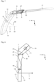
- the display device 1 comprises a holding device 2 which can be placed on the head of a user and which, in the embodiment described here, is designed as a conventional spectacle frame, as well as a first and second spectacle lens 3, 4 which are fastened to the holding device 2.
- the holding device 2 with the spectacle lenses 3 and 4 can be designed, for example, as sports glasses, sunglasses and/or spectacles for correcting ametropia, wherein a virtual image can be reflected onto the user's facial image via the first spectacle lens 3, as described below.
- the display device 1 comprises an image generation module 5, which has an image generator 6 (e.g., an OLED module) with which an image can be generated that is to be reflected into the user's field of vision as the virtual image.
- the display device 1 has an imaging optics 7, which contains an optical element 8 arranged between the image generator 6 and the first spectacle lens 3.
- the first spectacle lens 3 itself also serves as part of the imaging optics 7.
- the imaging optics 7 is designed as such as an imaging optics 7 according to the invention and is preferably designed for a display device that can be placed on the head of a user and generates an image.
- the imaging optics 7 is shown here only to illustrate its inventive design with the holding device 2 according to Fig. 1 described. However, the imaging optics 7 can also be designed for any other holding device.
- the imaging optics 7 according to the invention is in connection with Fig. 1 to 7 described below as having an air gap between the optical element 8 and the spectacle lens 3. However, this only serves to clarify the imaging optics 7 according to the invention, which is a single piece, so that no air gap is present. Either the optical element 8 and the spectacle lens 3 are connected to one another in such a way that the image to be guided by the image generator 6 does not have to pass through an air gap when guided in the optical element 8 and the spectacle lens 3, or the optical element 8 and the spectacle lens 3 are already manufactured as a single piece.
- the entrance surface F1 is also described as flat, but according to the invention it has a curvature.
- the imager 6 is designed as a planar imager with a plurality of pixels arranged, for example, in columns and rows, with each pixel being able to emit a light beam 9. By appropriately controlling the pixels, the desired image can be generated.
- Fig. 2 The beam path of a light beam is shown as a representative of the light bundles 9, so that the light beam 9 is also referred to below.
- the light beam 9 emanating from the imager 6 enters the optical element 8 via a planar entrance surface F1 and strikes an opposite planar reflection surface F2.
- the light beam 9 is reflected back from the reflection surface F2 to the entrance surface F1 and again strikes the entrance surface F1, but at a different location than where it enters the image generation module 5 and at an angle such that the light beam 9 is reflected due to total internal reflection to another planar reflection surface F3.
- Fig. 2 As can be seen, further reflections occur at the flat reflection surfaces F4 and F5, and the light beam 9 then strikes the transparent exit surface F6, which is curved and thus has an imaging effect.
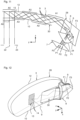
- the light beam 9 exits the optical element 8 via the exit surface F6, passes through the air gap to the rear side 10 of the first spectacle lens 3, and enters the first spectacle lens 3 via the rear side 10.
- a reflective surface 11 is formed in the spectacle lens 3, which deflects the light beam 9 towards the rear side 10 such that it undergoes total internal reflection at the rear side 10 and is reflected towards the front side 12 of the first spectacle lens. Total internal reflection also occurs at the front side 12, and after further total internal reflection at the rear side 10, the light beam 9 strikes a Fresnel surface 13 formed on the front side 12, which has several adjacent reflective facets 14.
- the reflective facets 14 result in a reflection towards the rear side 10 in such a way that the light beam 9 exits the spectacle lens 3 via the rear side 10 and can then be perceived by the user, who wears the display device 1 on their head as intended.
- the area of the first spectacle lens 3 with the reflection surface 11 can be referred to as the coupling section 15, wherein the reflection surface 11 is curved here and thus has an imaging effect.
- the area with the Fresnel surface 13 can be referred to as the coupling-out section 16, wherein the facets 14 can be curved here and thus the Fresnel surface 13 as a whole can also have an imaging effect.
- the back surface 10 of the spectacle lens can be flat or curved.
- the back surface 10 can be spherically curved.
- the front surface 12 of the spectacle lens can be flat or curved.
- the image generator 6 is arranged in the right temple 17 in the most space-saving way possible and thus extends perpendicular to the plane of the drawing according to Fig. 4 (x-direction) and on the other hand essentially in the longitudinal direction of the temple 17 (and thus from left to right in Fig. 4 or along the z-direction).
- the entrance surface F1 of the optical element 8 is oriented essentially parallel to the image generator 6 and thus also extends perpendicular to the plane of the drawing in Fig. 4 and from left to right in Fig. 4 .
- Fig. 5 to 7 is in the same way as in Fig. 2 to 4 a second embodiment of the display device not falling under the claimed invention is shown, wherein identical or similar elements are designated by identical reference numerals and for the description thereof reference is made to the above explanations.
- the optical element 8 is designed differently, since the coupling section 15 is formed on the edge surface 25 of the first spectacle lens 3 connecting the front and rear sides 12, 10.
- a cylindrical coupling surface 26 is formed on the edge surface 25.
- Surfaces F2, F7, and F8 are designed as reflection surfaces, with surface F2 being a flat surface and surfaces F7 and F8 being curved. In particular, they can be designed as freeform surfaces.
- the flat surface F6 serves both as a reflection surface and as an exit surface, with reflection occurring through total internal reflection.
- edge surfaces of the optical element 8 than the described surfaces F1, F2, F6-F8 are blackened and/or designed as absorbing surfaces in the same way as in the embodiment according to Fig. 2-4 trained.
- the deflection mirror 27 is arranged between the image generation module 5 and the optical element 8, so that a very compact design of the image generation module 5 together with the optical element 8 in the longitudinal direction of the right temple 17 is possible.
- FIG. 8 A highly schematic detailed sectional view of another embodiment of the imaging optics 7 not covered by the claimed invention is shown.
- the flat entrance surface F1 is tilted relative to the yz-plane. To illustrate this tilt, the actually rectangular entrance surface F1 is shown trapezoidally.
- the light beam 9 is drawn, which is intended to illustrate the light guidance and imaging in the optical element 8 and in the spectacle lens 3.
- the light beam 9 entering via the entrance surface F1 is reflected by the curved reflection surface F2 (which here is spherically curved, for example) to the exit surface F6 and enters through this into the spectacle lens 3, where it is guided by reflection at the front and rear surfaces 12, 10 up to the Fresnel surface 13.
- the outcoupling again takes place via the Fresnel surface 13.
- the exit surface F6 is directly connected to a corresponding surface of the spectacle lens 3.
- the connection can be made, for example, by cementing or gluing.
- the exit surface F6 and the corresponding surface of the spectacle lens 3 are shaped so that good surface contact can be established.
- the two surfaces are designed as flat surfaces.
- Fig. 10 is a further modification of the imaging optics 7 according to Fig. 8 shown.
- the spectacle lens 3 on the one hand, has no edge thickening.
- the interface at which the optical element 8 is connected to the spectacle lens 3 is located slightly differently. The interface is positioned such that two reflections occur in the optical element 8, so that in addition to the reflection surface F2, the latter also has the further reflection surface F3.
- This reflection surface F3 is shown as a flat surface. However, it is preferably curved. It can have a spherical curvature or a free-form curvature.
- a free-form curvature is understood to mean, in particular, a curvature that has different curvatures in two different main sections and/or that is curved and has no rotational symmetry.
- the free-form curvature can be neither spherical nor rotationally symmetrical.
- the embodiments according to Fig. 8 and 9 be designed so that the corresponding reflection takes place on a curved surface.
- the reflection is in Fig. 8 and 9 designated by the reference numeral 31. This means that in this area the interface can be correspondingly curved.
- the advantage is that the previously necessary coupling into the spectacle lens 3 via a separate interface is avoided. This leads to the advantage that refractions occurring at the interface are no longer present.
- the light or light beam 9 simply continues to propagate in the medium.
- the same optical material is used for the optical element 8 and the spectacle lens 3.
- FIGs 11 and 12 a further embodiment of the imaging optics 7 is shown, which is not covered by the claimed invention.
- the optical part 28 is formed in one piece, so that there is no internal boundary surface, such as a cement or adhesive surface, between the optical element 8 and the spectacle lens 3.
- the imager 6 is shown in perspective with a cover glass 24.
- the exit pupil 23 of the imaging optics 7 is shown, with the eye's center of rotation 22 located in the area of the exit pupil 23, which is intended to illustrate the intended use of the imaging optics 7.
- Fig. 12 the optical part 28 is shown in perspective.
- the front side 12 and the rear side 10 are each formed as spherically curved surfaces, with the radius of the front side 12 being 120 mm and the radius of the rear side 10 being 116 mm, so that the spectacle lens 3 has a thickness of 4 mm.
- the rear side 10 deviates from the spherical shape in the region A2.
- the region A2 is formed as a freeform surface, as will be described in detail below.
- the surfaces F1, F2, and F3 of the optical element 8 are also formed as freeform surfaces.
- Table 2 shows the optically used area of the respective area F1 - F3 or the respective area A1 - A6.
- xh denotes the width of the aperture area in the area's own coordinate system in the x-direction in millimeters.
- yh denotes the width of the aperture area in the area's own coordinate system in the y-direction in millimeters.
- xc denotes the x-decentration of the aperture area in the area's own coordinate system in millimeters
- yc denotes the y-decentration of the aperture area in the area's own coordinate system in millimeters.
- Rot denotes the rotation of the aperture area in the area's own coordinate system in degrees (°).
- the conic constant c for the freeform surface F1 is -2.08018.
- the conic constant c is zero.
- the curvature r of the freeform surface F1 is -0.11326.
- the curvature r of the other freeform surfaces is zero.
- the front side 12 is left in its spherical shape.
- at least two non-spherical surfaces here the three free-form surfaces F1, F2, and F3 are provided in the optical element 8, which are designed to achieve the desired, most error-free imaging possible.
- an aspherical surface is provided here in the region A2 in the edge region 30 in order to have a further degree of freedom in correcting aberrations.
- the exit pupil 22 can have a large extension in the x-direction.
- the display device's sliding up and down on the nose is not disruptive. The user always sees the complete image displayed.
- the required installation space for the optical element 8 can be kept very small due to the provision of the aspherical surfaces.
- the virtual image is reflected into the user's field of vision via the right spectacle lens 3.
- the left spectacle lens 4 In this case, only the optical element 8 and the image generation module 5 need be arranged in the left temple 19.
- the display device 1 can be designed such that information or virtual images are reflected via both lenses 3, 4. The reflection can be carried out in such a way that a three-dimensional image impression is created. However, this is not absolutely necessary.
- the lenses 3, 4 can have a refractive power of zero or a refractive power other than zero (in particular for correcting ametropia).
- the holding device 2 does not have to be designed as a glasses-like holding device. Any other type of holding device is also possible with which the display device can be placed or worn on the user's head.
Landscapes
- Physics & Mathematics (AREA)
- General Physics & Mathematics (AREA)
- Optics & Photonics (AREA)
- Health & Medical Sciences (AREA)
- Ophthalmology & Optometry (AREA)
- General Health & Medical Sciences (AREA)
- Lenses (AREA)
Claims (15)
- Optique d'imagerie pour un dispositif d'affichage pouvant être placé sur la tête d'un utilisateur et générant une image, comprenantun élément optique (8), qui présente une surface d'entrée (F1), et un verre de lunettes (3, 4), qui présente une portion de couplage de sortie (16),l'optique d'imagerie (7) étant adaptée pour guider dans l'élément optique (8) l'image générée acheminée à l'élément optique (8) par le biais de la surface d'entrée (F1), injecter celle-ci dans le verre de lunettes (3, 4), dans lequel elle est guidée jusqu'à la portion de couplage de sortie (16) et émise en sortie par le biais de la portion de couplage de sortie (16) afin de générer une image virtuelle,le verre de lunettes (3, 4) présentant un côté arrière (10) ainsi qu'un côté avant (12),l'élément optique (8) présentant, outre la surface d'entrée (F1), au moins une surface limite extérieure (F2) réfléchissante sur laquelle l'image générée est réfléchie pour être guidée dans l'élément optique (8),l'élément optique (8) et le verre de lunettes (3, 4) étant réalisés ensemble sous la forme d'une pièce optique d'un seul tenant,l'au moins une surface limite extérieure (F2) réfléchissante et la surface d'entrée (F1) étant des surfaces autres que le côté arrière (10) et le côté avant (12) du verre de lunettes (3, 4), et le côté arrière (10) étant réalisé sous la forme d'un côté arrière (10) plan ou incurvé et le côté avant (12) sous la forme d'un côté avant (12) plan ou incurvé,caractérisée en ce quela surface d'entrée (F1) est de configuration incurvée ainsi que transmissive pour l'injection de l'image générée dans l'élément optique (8) et réfléchissante pour la réflexion de l'image générée dans l'élément optique (8).
- Optique d'imagerie selon la revendication 1, l'au moins une surface limite extérieure (F2) étant de configuration incurvée, de sorte que l'élément optique (8) présente une propriété d'imagerie.
- Optique d'imagerie selon la revendication 1 ou 2, le verre de lunettes présentant une puissance de réfraction non nulle pour corriger un défaut de vision.
- Optique d'imagerie selon l'une des revendications ci-dessus, le côté arrière (10) du verre de lunettes (3, 4) et/ou le côté avant (12) du verre de lunettes (3, 4) étant de configuration incurvée.
- Optique d'imagerie selon l'une des revendications ci-dessus, l'élément optique (8) présentant des surfaces limites qui ne servent pas au guidage et/ou à l'injection ou au couplage de sortie de l'image générée, les surfaces limites étant noircies et/ou absorbantes pour la lumière.
- Optique d'imagerie selon l'une des revendications ci-dessus, le verre de lunettes (3, 4) présentant une portion d'injection (15) espacée de la portion de couplage de sortie (16), l'image générée étant injectée par l'élément optique (8) dans le verre de lunettes (3, 4) par le biais de la portion d'injection (15) et étant guidée dans le verre de lunettes (3, 4) par réflexion jusqu'à la portion de couplage de sortie (16).
- Optique d'imagerie selon la revendication 6, le verre de lunettes (3, 4) présentant la portion d'injection (15) dans une zone de bord (30), la zone de bord présentant une épaisseur supérieure à la zone du verre de lunettes (3, 4) dans laquelle se trouve la portion de couplage de sortie (16).
- Optique d'imagerie selon la revendication 6 ou 7, le côté avant (12) et le côté arrière (10) du verre de lunettes (3, 4) présentant chacun un tracé de courbure prédéterminé, le tracé de courbure du côté avant et/ou arrière (12, 10) du verre de lunettes (3, 4) s'écartant du tracé de courbure prédéterminé correspondant du côté avant et/ou arrière (12, 10) dans la zone de la portion d'injection (15), de telle sorte qu'il existe une épaisseur plus importante du verre de lunettes (3, 4) dans la zone de la portion d'injection (15) en comparaison de l'épaisseur dans la zone de la portion d'injection (15) qui résulterait du tracé de courbure prédéterminé.
- Optique d'imagerie selon la revendication 6, 7 ou 8, le côté avant (12) et le côté arrière (10) du verre de lunettes (3, 4) présentant respectivement une courbure sphérique, le côté arrière (10) présentant dans la zone de la portion d'injection (15) un tracé de courbure différent de la courbure sphérique.
- Optique d'imagerie selon l'une des revendications ci-dessus, ladite surface réfléchissante (F2) de l'élément optique (8) étant réalisée sous la forme d'une surface asphérique.
- Optique d'imagerie selon la revendication 10, la surface asphérique ne présentant pas de symétrie de rotation.
- Optique d'imagerie selon l'une des revendications ci-dessus,
la surface d'entrée incurvée (F1) étant réalisée sous la forme d'une surface asphérique ou d'une surface de forme libre. - Optique d'imagerie selon l'une des revendications ci-dessus,
la pièce optique, vue de dessus, présentant une forme en L. - Dispositif d'affichage comprenantun dispositif de maintien pouvant être placé sur la tête d'un utilisateur (2),un module de génération d'image (5) fixé sur le dispositif de maintien, qui génère une image,et une optique d'imagerie (8) selon l'une des revendications ci-dessus, fixée au dispositif de maintien (2),qui reproduit l'image générée lorsque le dispositif de maintien (2) est placé sur la tête, de telle sorte que l'utilisateur puisse la percevoir comme une image virtuelle.
- Dispositif d'affichage selon la revendication 14, le dispositif de maintien (2) étant réalisé à la manière de lunettes et possédant une première et une deuxième branches de lunettes (17, 19), l'élément optique (8) étant disposé au moins partiellement dans l'une des deux branches de lunettes (17, 19).
Applications Claiming Priority (2)
| Application Number | Priority Date | Filing Date | Title |
|---|---|---|---|
| DE102013223964.5A DE102013223964B3 (de) | 2013-11-22 | 2013-11-22 | Abbildungsoptik sowie Anzeigevorrichtung mit einer solchen Abbildungsoptik |
| PCT/EP2014/075334 WO2015075207A1 (fr) | 2013-11-22 | 2014-11-21 | Optique d'imagerie et dispositif d'affichage présentant une telle optique d'imagerie |
Publications (2)
| Publication Number | Publication Date |
|---|---|
| EP3072005A1 EP3072005A1 (fr) | 2016-09-28 |
| EP3072005B1 true EP3072005B1 (fr) | 2025-03-26 |
Family
ID=51945900
Family Applications (1)
| Application Number | Title | Priority Date | Filing Date |
|---|---|---|---|
| EP14802064.7A Active EP3072005B1 (fr) | 2013-11-22 | 2014-11-21 | Optique d'imagerie et dispositif d'affichage présentant une telle optique d'imagerie |
Country Status (7)
| Country | Link |
|---|---|
| US (1) | US10139626B2 (fr) |
| EP (1) | EP3072005B1 (fr) |
| JP (1) | JP6527512B2 (fr) |
| KR (1) | KR102291744B1 (fr) |
| CN (1) | CN105765443B (fr) |
| DE (1) | DE102013223964B3 (fr) |
| WO (1) | WO2015075207A1 (fr) |
Families Citing this family (70)
| Publication number | Priority date | Publication date | Assignee | Title |
|---|---|---|---|---|
| GB0522968D0 (en) | 2005-11-11 | 2005-12-21 | Popovich Milan M | Holographic illumination device |
| GB0718706D0 (en) | 2007-09-25 | 2007-11-07 | Creative Physics Ltd | Method and apparatus for reducing laser speckle |
| US9335604B2 (en) | 2013-12-11 | 2016-05-10 | Milan Momcilo Popovich | Holographic waveguide display |
| US11726332B2 (en) | 2009-04-27 | 2023-08-15 | Digilens Inc. | Diffractive projection apparatus |
| US11204540B2 (en) | 2009-10-09 | 2021-12-21 | Digilens Inc. | Diffractive waveguide providing a retinal image |
| WO2012136970A1 (fr) | 2011-04-07 | 2012-10-11 | Milan Momcilo Popovich | Dispositif d'élimination de la granularité laser basé sur une diversité angulaire |
| EP2748670B1 (fr) | 2011-08-24 | 2015-11-18 | Rockwell Collins, Inc. | Affichage de données portable |
| WO2016020630A2 (fr) | 2014-08-08 | 2016-02-11 | Milan Momcilo Popovich | Illuminateur laser en guide d'ondes comprenant un dispositif de déchatoiement |
| US10670876B2 (en) | 2011-08-24 | 2020-06-02 | Digilens Inc. | Waveguide laser illuminator incorporating a despeckler |
| WO2013102759A2 (fr) | 2012-01-06 | 2013-07-11 | Milan Momcilo Popovich | Capteur d'image à contact utilisant des réseaux de bragg commutables |
| CN103562802B (zh) | 2012-04-25 | 2016-08-17 | 罗克韦尔柯林斯公司 | 全息广角显示器 |
| US9456744B2 (en) | 2012-05-11 | 2016-10-04 | Digilens, Inc. | Apparatus for eye tracking |
| US9933684B2 (en) * | 2012-11-16 | 2018-04-03 | Rockwell Collins, Inc. | Transparent waveguide display providing upper and lower fields of view having a specific light output aperture configuration |
| WO2014188149A1 (fr) | 2013-05-20 | 2014-11-27 | Milan Momcilo Popovich | Dispositif holographique de suivi d'un œil à guide d'onde |
| WO2015015138A1 (fr) | 2013-07-31 | 2015-02-05 | Milan Momcilo Popovich | Méthode et appareil de détection d'une image par contact |
| US20160363769A1 (en) * | 2013-11-25 | 2016-12-15 | Sharp Kabushiki Kaisha | Light guide and head mounted display |
| WO2016020632A1 (fr) | 2014-08-08 | 2016-02-11 | Milan Momcilo Popovich | Procédé pour gravure par pressage et réplication holographique |
| US10241330B2 (en) | 2014-09-19 | 2019-03-26 | Digilens, Inc. | Method and apparatus for generating input images for holographic waveguide displays |
| WO2016046514A1 (fr) | 2014-09-26 | 2016-03-31 | LOKOVIC, Kimberly, Sun | Dispositif de poursuite optique à guide d'ondes holographique |
| DE102014119550B4 (de) * | 2014-12-23 | 2022-05-12 | tooz technologies GmbH | Abbildungsoptik zum Erzeugen eines virtuellen Bildes und Datenbrille |
| WO2016113534A1 (fr) | 2015-01-12 | 2016-07-21 | Milan Momcilo Popovich | Affichage à guide d'ondes isolé de l'environnement |
| EP3245551B1 (fr) | 2015-01-12 | 2019-09-18 | DigiLens Inc. | Afficheurs à champ lumineux et à guide d'ondes |
| WO2016116733A1 (fr) | 2015-01-20 | 2016-07-28 | Milan Momcilo Popovich | Lidar à guide d'ondes holographique |
| US9632226B2 (en) | 2015-02-12 | 2017-04-25 | Digilens Inc. | Waveguide grating device |
| US10459145B2 (en) | 2015-03-16 | 2019-10-29 | Digilens Inc. | Waveguide device incorporating a light pipe |
| US10591756B2 (en) | 2015-03-31 | 2020-03-17 | Digilens Inc. | Method and apparatus for contact image sensing |
| CN112882233B (zh) * | 2015-05-19 | 2023-08-01 | 奇跃公司 | 双复合光场装置 |
| DE102015114833A1 (de) * | 2015-09-04 | 2017-03-09 | Carl Zeiss Smart Optics Gmbh | Brillenglas für eine Abbildungsoptik zum Erzeugen eines virtuellen Bildes und Verfahren zum Herstellen eines derartigen Brillenglases |
| DE102015116297A1 (de) * | 2015-09-25 | 2017-03-30 | Carl Zeiss Smart Optics Gmbh | Abbildungsoptik sowie Anzeigevorrichtung mit einer solchen Abbildungsoptik |
| DE102015116402A1 (de) | 2015-09-28 | 2017-03-30 | Carl Zeiss Smart Optics Gmbh | Optisches Bauteil und Verfahren zu seiner Herstellung |
| CN113759555B (zh) | 2015-10-05 | 2024-09-20 | 迪吉伦斯公司 | 波导显示器 |
| DE102015117557B4 (de) | 2015-10-15 | 2020-06-10 | tooz technologies GmbH | Brillenglas für Abbildungsoptik zum Erzeugen eines virtuellen Bildes und Datenbrille |
| JP6819221B2 (ja) * | 2015-12-25 | 2021-01-27 | セイコーエプソン株式会社 | 虚像表示装置 |
| US10983340B2 (en) | 2016-02-04 | 2021-04-20 | Digilens Inc. | Holographic waveguide optical tracker |
| CN108780224B (zh) | 2016-03-24 | 2021-08-03 | 迪吉伦斯公司 | 用于提供偏振选择性全息波导装置的方法和设备 |
| JP6734933B2 (ja) | 2016-04-11 | 2020-08-05 | ディジレンズ インコーポレイテッド | 構造化光投影のためのホログラフィック導波管装置 |
| US11513350B2 (en) | 2016-12-02 | 2022-11-29 | Digilens Inc. | Waveguide device with uniform output illumination |
| DE102016124538A1 (de) | 2016-12-15 | 2018-06-21 | tooz technologies GmbH | Datenbrille, Brillenglas für eine Datenbrille und Verfahren zum Generieren eines Bildes auf der Netzhaut |
| WO2018129398A1 (fr) | 2017-01-05 | 2018-07-12 | Digilens, Inc. | Dispositifs d'affichage tête haute vestimentaires |
| CN106681005B (zh) * | 2017-02-16 | 2019-03-15 | 北京京东方光电科技有限公司 | 一种虚拟现实眼镜 |
| JP6852501B2 (ja) * | 2017-03-28 | 2021-03-31 | セイコーエプソン株式会社 | 表示装置 |
| WO2019024992A1 (fr) | 2017-08-02 | 2019-02-07 | Huawei Technologies Co., Ltd. | Monture de lunettes |
| DE102017119440A1 (de) | 2017-08-24 | 2019-02-28 | Carl Zeiss Ag | Gekrümmter Lichtleiter, Abbildungsoptik und HMD |
| WO2019039502A1 (fr) * | 2017-08-24 | 2019-02-28 | キヤノン株式会社 | Élément optique réfléchissant et dispositif d'appareil de prise de vues stéréo |
| EP3698214A4 (fr) | 2017-10-16 | 2021-10-27 | Digilens Inc. | Systèmes et procédés de multiplication de la résolution d'image d'un affichage pixélisé |
| CN207965356U (zh) * | 2017-11-14 | 2018-10-12 | 塔普翊海(上海)智能科技有限公司 | 一种近眼可透视头显光学系统 |
| WO2019126175A1 (fr) * | 2017-12-20 | 2019-06-27 | Vuzix Corporation | Système d'affichage à réalité augmentée |
| WO2019135837A1 (fr) | 2018-01-08 | 2019-07-11 | Digilens, Inc. | Systèmes et procédés de fabrication de cellules de guide d'ondes |
| CN114721242B (zh) | 2018-01-08 | 2025-08-15 | 迪吉伦斯公司 | 用于制造光学波导的方法 |
| CN111566571B (zh) | 2018-01-08 | 2022-05-13 | 迪吉伦斯公司 | 波导单元格中全息光栅高吞吐量记录的系统和方法 |
| US10914950B2 (en) | 2018-01-08 | 2021-02-09 | Digilens Inc. | Waveguide architectures and related methods of manufacturing |
| EP4372451A3 (fr) | 2018-03-16 | 2024-08-14 | Digilens Inc. | Guides d'ondes holographiques a regulation de birefringence et procedes de fabrication |
| US11402801B2 (en) | 2018-07-25 | 2022-08-02 | Digilens Inc. | Systems and methods for fabricating a multilayer optical structure |
| WO2020149956A1 (fr) | 2019-01-14 | 2020-07-23 | Digilens Inc. | Affichage de guide d'ondes holographique avec couche de commande de lumière |
| DE102019102586A1 (de) | 2019-02-01 | 2020-08-06 | tooz technologies GmbH | Lichtleitanordnung, Abbildungsoptik, Head Mounted Display und Verfahren zum Verbessern der Abbildungsqualität einer Abbildungsoptik |
| US20200247017A1 (en) | 2019-02-05 | 2020-08-06 | Digilens Inc. | Methods for Compensating for Optical Surface Nonuniformity |
| KR102866596B1 (ko) | 2019-02-15 | 2025-09-29 | 디지렌즈 인코포레이티드. | 일체형 격자를 이용하여 홀로그래픽 도파관 디스플레이를 제공하기 위한 방법 및 장치 |
| US20220283377A1 (en) | 2019-02-15 | 2022-09-08 | Digilens Inc. | Wide Angle Waveguide Display |
| WO2020186113A1 (fr) | 2019-03-12 | 2020-09-17 | Digilens Inc. | Rétroéclairage de guide d'ondes holographique et procédés de fabrication associés |
| CN113614610B (zh) * | 2019-03-20 | 2023-09-22 | 株式会社理光 | 虚像显示装置 |
| KR20220016990A (ko) | 2019-06-07 | 2022-02-10 | 디지렌즈 인코포레이티드. | 투과 및 반사 격자를 통합하는 도파관 및 관련 제조 방법 |
| US11681143B2 (en) | 2019-07-29 | 2023-06-20 | Digilens Inc. | Methods and apparatus for multiplying the image resolution and field-of-view of a pixelated display |
| WO2021041949A1 (fr) | 2019-08-29 | 2021-03-04 | Digilens Inc. | Réseaux de bragg sous vide et procédés de fabrication |
| KR20230119015A (ko) | 2020-12-21 | 2023-08-14 | 디지렌즈 인코포레이티드. | 도파로 기반 디스플레이에서의 홍목현상 억제 기술 |
| US12399326B2 (en) | 2021-01-07 | 2025-08-26 | Digilens Inc. | Grating structures for color waveguides |
| KR20230153459A (ko) | 2021-03-05 | 2023-11-06 | 디지렌즈 인코포레이티드. | 진공 주기적 구조체 및 제조 방법 |
| CN117178214A (zh) * | 2021-04-11 | 2023-12-05 | 鲁姆斯有限公司 | 包括具有二维扩展的光导光学元件的显示器 |
| DE102022113531A1 (de) | 2022-05-30 | 2023-11-30 | tooz technologies GmbH | Datenbrillenrahmen, Datenbrille und Brillenglas sowie Verfahren zum Montieren einer Datenbrille |
| DE102023211189A1 (de) * | 2023-11-10 | 2025-05-15 | Carl Zeiss Jena Gmbh | Hochauflösung Holocam durch Freiform-Belichtung |
| DE102023134822A1 (de) * | 2023-12-12 | 2025-06-12 | tooz technologies GmbH | Optische Anordnung mit Lichtwellenleiter zum Einstrahlen von virtuellen Bildern und Head-Mounted-Display |
Citations (3)
| Publication number | Priority date | Publication date | Assignee | Title |
|---|---|---|---|---|
| WO2001095027A2 (fr) * | 2000-06-05 | 2001-12-13 | Lumus Ltd. | Dilatateur de faisceau optique guide par un substrat |
| WO2007062098A2 (fr) * | 2005-11-21 | 2007-05-31 | Microvision, Inc. | Ecran d'affichage avec substrat a guidage d'image |
| WO2013173732A1 (fr) * | 2012-05-18 | 2013-11-21 | Reald Inc. | Agencement de guide d'onde éclairé de façon directionnelle |
Family Cites Families (27)
| Publication number | Priority date | Publication date | Assignee | Title |
|---|---|---|---|---|
| JPH11142783A (ja) * | 1997-11-12 | 1999-05-28 | Olympus Optical Co Ltd | 画像表示装置 |
| CN1171110C (zh) * | 1999-04-02 | 2004-10-13 | 奥林巴斯株式会社 | 观察光学系统及使用了该系统的图像显示装置 |
| JP4727034B2 (ja) * | 2000-11-28 | 2011-07-20 | オリンパス株式会社 | 観察光学系および撮像光学系 |
| JP4772204B2 (ja) * | 2001-04-13 | 2011-09-14 | オリンパス株式会社 | 観察光学系 |
| JP2004012703A (ja) * | 2002-06-05 | 2004-01-15 | Canon Inc | 画像観察装置および画像観察システム |
| JP2004029544A (ja) * | 2002-06-27 | 2004-01-29 | Nikon Corp | ホログラムコンバイナ光学系及び情報表示装置 |
| JP2004341411A (ja) * | 2003-05-19 | 2004-12-02 | Canon Inc | 光学系および画像表示装置 |
| JP2005084522A (ja) * | 2003-09-10 | 2005-03-31 | Nikon Corp | コンバイナ光学系 |
| WO2005093493A1 (fr) | 2004-03-29 | 2005-10-06 | Sony Corporation | Dispositif optique et dispositif de visualisation d’images virtuelles |
| FR2873212B1 (fr) | 2004-07-16 | 2011-06-10 | Essilor Int | Lentille opthalmique destinee a la realisation d'un afficheur optique |
| US20060126181A1 (en) | 2004-12-13 | 2006-06-15 | Nokia Corporation | Method and system for beam expansion in a display device |
| US7791822B2 (en) * | 2006-08-21 | 2010-09-07 | Konica Minolta Opto, Inc. | Focusing method and image-taking apparatus |
| JP2008046561A (ja) * | 2006-08-21 | 2008-02-28 | Konica Minolta Opto Inc | 光学系のフォーカシング方法 |
| DE112008000051A5 (de) | 2007-01-25 | 2009-11-12 | Rodenstock Gmbh | Brille und Brillenglas zur Dateneinspiegelung |
| DE102007004444B4 (de) * | 2007-01-26 | 2019-11-14 | tooz technologies GmbH | Multifunktions-Brillenglas, Verwendung eines solchen Multifunktions-Brillenglases in einer Datenbrille sowie Datenbrille |
| DE102008009095A1 (de) * | 2008-02-14 | 2009-08-20 | Carl Zeiss Ag | Durchsicht-Display-System |
| JP2010072150A (ja) * | 2008-09-17 | 2010-04-02 | Konica Minolta Holdings Inc | 映像表示装置およびヘッドマウントディスプレイ |
| EP2187188A1 (fr) * | 2008-11-13 | 2010-05-19 | X-Rite Europe GmbH | Dispositif de mesure de la lumière |
| FR2938934B1 (fr) * | 2008-11-25 | 2017-07-07 | Essilor Int - Cie Generale D'optique | Verre de lunettes procurant une vision ophtalmique et une vision supplementaire |
| DE102009010537B4 (de) * | 2009-02-25 | 2018-03-01 | Carl Zeiss Smart Optics Gmbh | Strahlvereiniger und Verwendung eines solchen in einer Anzeigevorrichtung |
| DE102010040962A1 (de) * | 2010-09-17 | 2012-03-22 | Carl Zeiss Ag | Anzeigevorrichtung mit einer auf den Kopf eines Benutzers aufsetzbaren Haltevorrichtung |
| JP2012123147A (ja) * | 2010-12-08 | 2012-06-28 | Seiko Epson Corp | 導光板、導光板の製造方法及び虚像表示装置 |
| JP6020113B2 (ja) * | 2012-02-24 | 2016-11-02 | セイコーエプソン株式会社 | 虚像表示装置 |
| JP6111636B2 (ja) * | 2012-02-24 | 2017-04-12 | セイコーエプソン株式会社 | 虚像表示装置 |
| CN103293675A (zh) * | 2012-02-24 | 2013-09-11 | 精工爱普生株式会社 | 虚像显示装置 |
| DE102013214700B4 (de) | 2013-07-26 | 2020-08-06 | tooz technologies GmbH | Brillenglas sowie Anzeigevorrichtung mit einem solchen Brillenglas |
| DE102013223963B4 (de) * | 2013-11-22 | 2015-07-02 | Carl Zeiss Ag | Abbildungsoptik sowie Anzeigevorrichtung mit einer solchen Abbildungsoptik |
-
2013
- 2013-11-22 DE DE102013223964.5A patent/DE102013223964B3/de active Active
-
2014
- 2014-11-21 KR KR1020167015284A patent/KR102291744B1/ko active Active
- 2014-11-21 WO PCT/EP2014/075334 patent/WO2015075207A1/fr not_active Ceased
- 2014-11-21 JP JP2016532525A patent/JP6527512B2/ja active Active
- 2014-11-21 CN CN201480063663.6A patent/CN105765443B/zh active Active
- 2014-11-21 US US15/038,466 patent/US10139626B2/en active Active
- 2014-11-21 EP EP14802064.7A patent/EP3072005B1/fr active Active
Patent Citations (3)
| Publication number | Priority date | Publication date | Assignee | Title |
|---|---|---|---|---|
| WO2001095027A2 (fr) * | 2000-06-05 | 2001-12-13 | Lumus Ltd. | Dilatateur de faisceau optique guide par un substrat |
| WO2007062098A2 (fr) * | 2005-11-21 | 2007-05-31 | Microvision, Inc. | Ecran d'affichage avec substrat a guidage d'image |
| WO2013173732A1 (fr) * | 2012-05-18 | 2013-11-21 | Reald Inc. | Agencement de guide d'onde éclairé de façon directionnelle |
Also Published As
| Publication number | Publication date |
|---|---|
| EP3072005A1 (fr) | 2016-09-28 |
| JP6527512B2 (ja) | 2019-06-05 |
| CN105765443A (zh) | 2016-07-13 |
| KR20160090310A (ko) | 2016-07-29 |
| CN105765443B (zh) | 2019-03-01 |
| DE102013223964B3 (de) | 2015-05-13 |
| US10139626B2 (en) | 2018-11-27 |
| KR102291744B1 (ko) | 2021-08-19 |
| WO2015075207A1 (fr) | 2015-05-28 |
| JP2016541018A (ja) | 2016-12-28 |
| US20160299344A1 (en) | 2016-10-13 |
Similar Documents
| Publication | Publication Date | Title |
|---|---|---|
| EP3072005B1 (fr) | Optique d'imagerie et dispositif d'affichage présentant une telle optique d'imagerie | |
| EP3072006B1 (fr) | Optique de reproduction et dispositif d'affichage muni de ladite optique d'imagerie | |
| DE102014207499B4 (de) | Brillenglas für eine auf den Kopf eines Benutzers aufsetzbare und ein Bild erzeugende Anzeigevorrichtung | |
| EP3353588B1 (fr) | Dispositif d'affichage pourvu d'une optique de reproduction | |
| DE102014207492B4 (de) | Anzeigevorrichtung | |
| DE102013214700B4 (de) | Brillenglas sowie Anzeigevorrichtung mit einem solchen Brillenglas | |
| EP3237960B1 (fr) | Optique de reproduction permettant de produire une image virtuelle et lunettes intelligentes | |
| EP3132302B1 (fr) | Verre de lunettes destiné à un dispositif d'affichage pouvant être porté sur la tête d'un utilisateur et produisant une image | |
| DE102014207495B3 (de) | Brillenglas für eine auf den Kopf eines Benutzers aufsetzbare und ein Bild erzeugende Anzeigevorrichtung | |
| WO2015044305A1 (fr) | Verre de lunettes pour dispositif d'affichage générant une image et pouvant être placé sur la tête d'un utilisateur | |
| EP3049850A1 (fr) | Verre de lunette pour dispositif d'affichage pouvant être placé sur la tête d'un utilisateur afin de générer une image, ainsi que dispositif d'affichage équipé d'un tel verre de lunette | |
| EP3345043A1 (fr) | Verre de lunetterie conçu pour un système optique de reproduction destiné à générer une image virtuelle, et procédé de production d'un tel verre de lunetterie | |
| EP3049851A1 (fr) | Verre de lunette pour dispositif d'affichage pouvant être placé sur la tête d'un utilisateur afin de générer une image, ainsi que dispositif d'affichage équipé d'un tel verre de lunette | |
| DE102007046505B4 (de) | Anzeigevorrichtung und Stereo-Anzeigemodul | |
| EP3574368A1 (fr) | Verre de lunettes pour un dispositif d'affichage se posant sur la tête d'un utilisateur et produisant une image | |
| WO2017220474A1 (fr) | Verre de lunettes destiné à un dispositif d'affichage pouvant être placé sur la tête d'un utilisateur et produisant une image, et dispositif d'affichage muni d'un verre de lunettes de ce type | |
| DE102024114655A1 (de) | Brillenglas für eine auf den Kopf eines Benutzers aufsetzbare und ein Bild erzeugende Anzeigevorrichtung sowie Anzeigevorrichtung mit einem solchen Brillenglas |
Legal Events
| Date | Code | Title | Description |
|---|---|---|---|
| PUAI | Public reference made under article 153(3) epc to a published international application that has entered the european phase |
Free format text: ORIGINAL CODE: 0009012 |
|
| 17P | Request for examination filed |
Effective date: 20160509 |
|
| AK | Designated contracting states |
Kind code of ref document: A1 Designated state(s): AL AT BE BG CH CY CZ DE DK EE ES FI FR GB GR HR HU IE IS IT LI LT LU LV MC MK MT NL NO PL PT RO RS SE SI SK SM TR |
|
| AX | Request for extension of the european patent |
Extension state: BA ME |
|
| RAP1 | Party data changed (applicant data changed or rights of an application transferred) |
Owner name: CARL ZEISS SMART OPTICS GMBH |
|
| DAX | Request for extension of the european patent (deleted) | ||
| RAP1 | Party data changed (applicant data changed or rights of an application transferred) |
Owner name: TOOZ TECHNOLOGIES GMBH |
|
| STAA | Information on the status of an ep patent application or granted ep patent |
Free format text: STATUS: EXAMINATION IS IN PROGRESS |
|
| 17Q | First examination report despatched |
Effective date: 20220607 |
|
| GRAP | Despatch of communication of intention to grant a patent |
Free format text: ORIGINAL CODE: EPIDOSNIGR1 |
|
| STAA | Information on the status of an ep patent application or granted ep patent |
Free format text: STATUS: GRANT OF PATENT IS INTENDED |
|
| GRAJ | Information related to disapproval of communication of intention to grant by the applicant or resumption of examination proceedings by the epo deleted |
Free format text: ORIGINAL CODE: EPIDOSDIGR1 |
|
| STAA | Information on the status of an ep patent application or granted ep patent |
Free format text: STATUS: EXAMINATION IS IN PROGRESS |
|
| RIC1 | Information provided on ipc code assigned before grant |
Ipc: G02B 6/00 20060101ALN20241023BHEP Ipc: G02C 7/08 20060101ALI20241023BHEP Ipc: G02B 27/01 20060101AFI20241023BHEP |
|
| GRAP | Despatch of communication of intention to grant a patent |
Free format text: ORIGINAL CODE: EPIDOSNIGR1 |
|
| STAA | Information on the status of an ep patent application or granted ep patent |
Free format text: STATUS: GRANT OF PATENT IS INTENDED |
|
| INTG | Intention to grant announced |
Effective date: 20241118 |
|
| INTC | Intention to grant announced (deleted) | ||
| RIC1 | Information provided on ipc code assigned before grant |
Ipc: G02B 6/00 20060101ALN20241127BHEP Ipc: G02C 7/08 20060101ALI20241127BHEP Ipc: G02B 27/01 20060101AFI20241127BHEP |
|
| RIN1 | Information on inventor provided before grant (corrected) |
Inventor name: RIEDEL, LISA Inventor name: RUDOLPH, GUENTER Inventor name: LINDIG, KARSTEN Inventor name: DOBSCHAL, HANS-JUERGEN |
|
| INTG | Intention to grant announced |
Effective date: 20241210 |
|
| GRAJ | Information related to disapproval of communication of intention to grant by the applicant or resumption of examination proceedings by the epo deleted |
Free format text: ORIGINAL CODE: EPIDOSDIGR1 |
|
| STAA | Information on the status of an ep patent application or granted ep patent |
Free format text: STATUS: EXAMINATION IS IN PROGRESS |
|
| GRAP | Despatch of communication of intention to grant a patent |
Free format text: ORIGINAL CODE: EPIDOSNIGR1 |
|
| STAA | Information on the status of an ep patent application or granted ep patent |
Free format text: STATUS: GRANT OF PATENT IS INTENDED |
|
| GRAS | Grant fee paid |
Free format text: ORIGINAL CODE: EPIDOSNIGR3 |
|
| GRAA | (expected) grant |
Free format text: ORIGINAL CODE: 0009210 |
|
| STAA | Information on the status of an ep patent application or granted ep patent |
Free format text: STATUS: THE PATENT HAS BEEN GRANTED |
|
| INTC | Intention to grant announced (deleted) | ||
| RIC1 | Information provided on ipc code assigned before grant |
Ipc: G02B 6/00 20060101ALN20250122BHEP Ipc: G02C 7/08 20060101ALI20250122BHEP Ipc: G02B 27/01 20060101AFI20250122BHEP |
|
| INTG | Intention to grant announced |
Effective date: 20250130 |
|
| AK | Designated contracting states |
Kind code of ref document: B1 Designated state(s): AL AT BE BG CH CY CZ DE DK EE ES FI FR GB GR HR HU IE IS IT LI LT LU LV MC MK MT NL NO PL PT RO RS SE SI SK SM TR |
|
| REG | Reference to a national code |
Ref country code: GB Ref legal event code: FG4D Free format text: NOT ENGLISH |
|
| REG | Reference to a national code |
Ref country code: CH Ref legal event code: EP |
|
| REG | Reference to a national code |
Ref country code: DE Ref legal event code: R096 Ref document number: 502014016923 Country of ref document: DE |
|
| REG | Reference to a national code |
Ref country code: IE Ref legal event code: FG4D Free format text: LANGUAGE OF EP DOCUMENT: GERMAN |
|
| PG25 | Lapsed in a contracting state [announced via postgrant information from national office to epo] |
Ref country code: RS Free format text: LAPSE BECAUSE OF FAILURE TO SUBMIT A TRANSLATION OF THE DESCRIPTION OR TO PAY THE FEE WITHIN THE PRESCRIBED TIME-LIMIT Effective date: 20250626 |
|
| PG25 | Lapsed in a contracting state [announced via postgrant information from national office to epo] |
Ref country code: FI Free format text: LAPSE BECAUSE OF FAILURE TO SUBMIT A TRANSLATION OF THE DESCRIPTION OR TO PAY THE FEE WITHIN THE PRESCRIBED TIME-LIMIT Effective date: 20250326 |
|
| REG | Reference to a national code |
Ref country code: LT Ref legal event code: MG9D |
|
| PG25 | Lapsed in a contracting state [announced via postgrant information from national office to epo] |
Ref country code: NO Free format text: LAPSE BECAUSE OF FAILURE TO SUBMIT A TRANSLATION OF THE DESCRIPTION OR TO PAY THE FEE WITHIN THE PRESCRIBED TIME-LIMIT Effective date: 20250626 |
|
| PG25 | Lapsed in a contracting state [announced via postgrant information from national office to epo] |
Ref country code: HR Free format text: LAPSE BECAUSE OF FAILURE TO SUBMIT A TRANSLATION OF THE DESCRIPTION OR TO PAY THE FEE WITHIN THE PRESCRIBED TIME-LIMIT Effective date: 20250326 |
|
| PG25 | Lapsed in a contracting state [announced via postgrant information from national office to epo] |
Ref country code: LV Free format text: LAPSE BECAUSE OF FAILURE TO SUBMIT A TRANSLATION OF THE DESCRIPTION OR TO PAY THE FEE WITHIN THE PRESCRIBED TIME-LIMIT Effective date: 20250326 |
|
| PG25 | Lapsed in a contracting state [announced via postgrant information from national office to epo] |
Ref country code: GR Free format text: LAPSE BECAUSE OF FAILURE TO SUBMIT A TRANSLATION OF THE DESCRIPTION OR TO PAY THE FEE WITHIN THE PRESCRIBED TIME-LIMIT Effective date: 20250627 Ref country code: BG Free format text: LAPSE BECAUSE OF FAILURE TO SUBMIT A TRANSLATION OF THE DESCRIPTION OR TO PAY THE FEE WITHIN THE PRESCRIBED TIME-LIMIT Effective date: 20250326 |
|
| REG | Reference to a national code |
Ref country code: NL Ref legal event code: MP Effective date: 20250326 |
|
| PG25 | Lapsed in a contracting state [announced via postgrant information from national office to epo] |
Ref country code: NL Free format text: LAPSE BECAUSE OF FAILURE TO SUBMIT A TRANSLATION OF THE DESCRIPTION OR TO PAY THE FEE WITHIN THE PRESCRIBED TIME-LIMIT Effective date: 20250326 |
|
| PG25 | Lapsed in a contracting state [announced via postgrant information from national office to epo] |
Ref country code: SE Free format text: LAPSE BECAUSE OF FAILURE TO SUBMIT A TRANSLATION OF THE DESCRIPTION OR TO PAY THE FEE WITHIN THE PRESCRIBED TIME-LIMIT Effective date: 20250326 |
|
| PG25 | Lapsed in a contracting state [announced via postgrant information from national office to epo] |
Ref country code: SM Free format text: LAPSE BECAUSE OF FAILURE TO SUBMIT A TRANSLATION OF THE DESCRIPTION OR TO PAY THE FEE WITHIN THE PRESCRIBED TIME-LIMIT Effective date: 20250326 |
|
| PG25 | Lapsed in a contracting state [announced via postgrant information from national office to epo] |
Ref country code: PT Free format text: LAPSE BECAUSE OF FAILURE TO SUBMIT A TRANSLATION OF THE DESCRIPTION OR TO PAY THE FEE WITHIN THE PRESCRIBED TIME-LIMIT Effective date: 20250728 Ref country code: ES Free format text: LAPSE BECAUSE OF FAILURE TO SUBMIT A TRANSLATION OF THE DESCRIPTION OR TO PAY THE FEE WITHIN THE PRESCRIBED TIME-LIMIT Effective date: 20250326 |
|
| PG25 | Lapsed in a contracting state [announced via postgrant information from national office to epo] |
Ref country code: IT Free format text: LAPSE BECAUSE OF FAILURE TO SUBMIT A TRANSLATION OF THE DESCRIPTION OR TO PAY THE FEE WITHIN THE PRESCRIBED TIME-LIMIT Effective date: 20250326 Ref country code: PL Free format text: LAPSE BECAUSE OF FAILURE TO SUBMIT A TRANSLATION OF THE DESCRIPTION OR TO PAY THE FEE WITHIN THE PRESCRIBED TIME-LIMIT Effective date: 20250326 |
|
| PG25 | Lapsed in a contracting state [announced via postgrant information from national office to epo] |
Ref country code: EE Free format text: LAPSE BECAUSE OF FAILURE TO SUBMIT A TRANSLATION OF THE DESCRIPTION OR TO PAY THE FEE WITHIN THE PRESCRIBED TIME-LIMIT Effective date: 20250326 |
|
| PG25 | Lapsed in a contracting state [announced via postgrant information from national office to epo] |
Ref country code: RO Free format text: LAPSE BECAUSE OF FAILURE TO SUBMIT A TRANSLATION OF THE DESCRIPTION OR TO PAY THE FEE WITHIN THE PRESCRIBED TIME-LIMIT Effective date: 20250326 |
|
| PG25 | Lapsed in a contracting state [announced via postgrant information from national office to epo] |
Ref country code: SK Free format text: LAPSE BECAUSE OF FAILURE TO SUBMIT A TRANSLATION OF THE DESCRIPTION OR TO PAY THE FEE WITHIN THE PRESCRIBED TIME-LIMIT Effective date: 20250326 |
|
| PG25 | Lapsed in a contracting state [announced via postgrant information from national office to epo] |
Ref country code: IS Free format text: LAPSE BECAUSE OF FAILURE TO SUBMIT A TRANSLATION OF THE DESCRIPTION OR TO PAY THE FEE WITHIN THE PRESCRIBED TIME-LIMIT Effective date: 20250726 |
|
| REG | Reference to a national code |
Ref country code: DE Ref legal event code: R097 Ref document number: 502014016923 Country of ref document: DE |
|
| PGFP | Annual fee paid to national office [announced via postgrant information from national office to epo] |
Ref country code: DE Payment date: 20251119 Year of fee payment: 12 |
|
| PGFP | Annual fee paid to national office [announced via postgrant information from national office to epo] |
Ref country code: GB Payment date: 20251120 Year of fee payment: 12 |
|
| PG25 | Lapsed in a contracting state [announced via postgrant information from national office to epo] |
Ref country code: DK Free format text: LAPSE BECAUSE OF FAILURE TO SUBMIT A TRANSLATION OF THE DESCRIPTION OR TO PAY THE FEE WITHIN THE PRESCRIBED TIME-LIMIT Effective date: 20250326 |
|
| PGFP | Annual fee paid to national office [announced via postgrant information from national office to epo] |
Ref country code: FR Payment date: 20251126 Year of fee payment: 12 |
|
| PG25 | Lapsed in a contracting state [announced via postgrant information from national office to epo] |
Ref country code: CZ Free format text: LAPSE BECAUSE OF FAILURE TO SUBMIT A TRANSLATION OF THE DESCRIPTION OR TO PAY THE FEE WITHIN THE PRESCRIBED TIME-LIMIT Effective date: 20250326 |
|
| PLBE | No opposition filed within time limit |
Free format text: ORIGINAL CODE: 0009261 |
|
| STAA | Information on the status of an ep patent application or granted ep patent |
Free format text: STATUS: NO OPPOSITION FILED WITHIN TIME LIMIT |
|
| REG | Reference to a national code |
Ref country code: CH Ref legal event code: L10 Free format text: ST27 STATUS EVENT CODE: U-0-0-L10-L00 (AS PROVIDED BY THE NATIONAL OFFICE) Effective date: 20260211 |
|
| 26N | No opposition filed |
Effective date: 20260105 |