EP3071921B1 - Reflector sight having virtual sighting - Google Patents
Reflector sight having virtual sighting Download PDFInfo
- Publication number
- EP3071921B1 EP3071921B1 EP14802848.3A EP14802848A EP3071921B1 EP 3071921 B1 EP3071921 B1 EP 3071921B1 EP 14802848 A EP14802848 A EP 14802848A EP 3071921 B1 EP3071921 B1 EP 3071921B1
- Authority
- EP
- European Patent Office
- Prior art keywords
- sighting device
- weapon
- target
- sighting
- sight
- Prior art date
- Legal status (The legal status is an assumption and is not a legal conclusion. Google has not performed a legal analysis and makes no representation as to the accuracy of the status listed.)
- Active
Links
- 238000005259 measurement Methods 0.000 claims description 11
- 230000007935 neutral effect Effects 0.000 claims description 5
- 230000003287 optical effect Effects 0.000 claims description 5
- 230000004297 night vision Effects 0.000 claims description 3
- 230000035939 shock Effects 0.000 claims description 3
- 238000001514 detection method Methods 0.000 claims 1
- 238000005286 illumination Methods 0.000 claims 1
- 230000008054 signal transmission Effects 0.000 claims 1
- 230000011514 reflex Effects 0.000 description 22
- 238000012937 correction Methods 0.000 description 10
- 230000005484 gravity Effects 0.000 description 8
- 238000010304 firing Methods 0.000 description 7
- 238000000034 method Methods 0.000 description 7
- 230000006870 function Effects 0.000 description 6
- 238000003825 pressing Methods 0.000 description 6
- 230000008569 process Effects 0.000 description 6
- 238000009434 installation Methods 0.000 description 5
- 239000011521 glass Substances 0.000 description 4
- 230000004438 eyesight Effects 0.000 description 3
- 230000008901 benefit Effects 0.000 description 2
- 230000008859 change Effects 0.000 description 2
- 238000012790 confirmation Methods 0.000 description 2
- 238000013461 design Methods 0.000 description 2
- 239000011159 matrix material Substances 0.000 description 2
- 230000000717 retained effect Effects 0.000 description 2
- 238000003860 storage Methods 0.000 description 2
- 230000006978 adaptation Effects 0.000 description 1
- 230000004075 alteration Effects 0.000 description 1
- 230000000712 assembly Effects 0.000 description 1
- 238000000429 assembly Methods 0.000 description 1
- 238000013016 damping Methods 0.000 description 1
- 230000003247 decreasing effect Effects 0.000 description 1
- 238000011156 evaluation Methods 0.000 description 1
- 239000004973 liquid crystal related substance Substances 0.000 description 1
- 238000004519 manufacturing process Methods 0.000 description 1
- 238000012545 processing Methods 0.000 description 1
- 230000009467 reduction Effects 0.000 description 1
- 230000000007 visual effect Effects 0.000 description 1
Images


Classifications
-
- F—MECHANICAL ENGINEERING; LIGHTING; HEATING; WEAPONS; BLASTING
- F41—WEAPONS
- F41G—WEAPON SIGHTS; AIMING
- F41G3/00—Aiming or laying means
- F41G3/06—Aiming or laying means with rangefinder
-
- F—MECHANICAL ENGINEERING; LIGHTING; HEATING; WEAPONS; BLASTING
- F41—WEAPONS
- F41G—WEAPON SIGHTS; AIMING
- F41G1/00—Sighting devices
- F41G1/30—Reflecting-sights specially adapted for smallarms or ordnance
-
- F—MECHANICAL ENGINEERING; LIGHTING; HEATING; WEAPONS; BLASTING
- F41—WEAPONS
- F41G—WEAPON SIGHTS; AIMING
- F41G1/00—Sighting devices
- F41G1/46—Sighting devices for particular applications
- F41G1/473—Sighting devices for particular applications for lead-indicating or range-finding, e.g. for use with rifles or shotguns
-
- F—MECHANICAL ENGINEERING; LIGHTING; HEATING; WEAPONS; BLASTING
- F41—WEAPONS
- F41G—WEAPON SIGHTS; AIMING
- F41G1/00—Sighting devices
- F41G1/46—Sighting devices for particular applications
- F41G1/48—Sighting devices for particular applications for firing grenades from rifles
-
- F—MECHANICAL ENGINEERING; LIGHTING; HEATING; WEAPONS; BLASTING
- F41—WEAPONS
- F41G—WEAPON SIGHTS; AIMING
- F41G3/00—Aiming or laying means
- F41G3/14—Indirect aiming means
- F41G3/16—Sighting devices adapted for indirect laying of fire
- F41G3/165—Sighting devices adapted for indirect laying of fire using a TV-monitor
Definitions
- the invention is concerned with a reflex sight with virtual sighting in the form of a simple, small and inexpensive sighting device for handguns for firing ammunition with extended and excessive trajectory.
- the sighting device contains a reflex sight with a micro display, so that in addition to the target mark, text and image information can also be displayed.
- small-scale reflex sights are used alone or often in conjunction with a main sight, e.g. Rifle scope, used. These reflex sights are well suited for accurate shooting with ammunition with a straight trajectory.
- a main sight e.g. Rifle scope
- these reflex sights are well suited for accurate shooting with ammunition with a straight trajectory.
- slow grenades e.g. Shooting grenades with an attachment on the assault rifle or with an independent system
- these sights are initially not suitable because of the greatly increased trajectory of the ammunition, because the stopping point can no longer be visibly displayed together with the target object in the field of view of the sight.
- a shooter can also precisely align a weapon if the target position and the actual position of the stopping point are shown to him.
- Reflex sights or red dot sights with a movable target point as in US 7,225,578 B2 Described or offered as devices such as Fire Control Unit BR8 from AIMPOINT or Fire Control System from MPRS (Multi Purpose Rifle System) from IMI are known.
- Fire Control Unit BR8 from AIMPOINT
- Fire Control System from MPRS (Multi Purpose Rifle System) from IMI
- these reflex sights are again high-rise.
- a mirror or a beam splitter in the beam path of the display has to be set mechanically with high angular accuracy in order to shift the target point in accordance with the ballistic correction, which makes these devices technically complex. Because of the large viewing window required, these visors cannot be combined with a magnifying optic.
- a reflex sight for aiming weapons with slow bullet speed is known, to which an electronic display device is assigned, which is controlled by electronics processing the data from distance measurement and movement of the target. Only the optimal target mark is made visible in the sight.
- the display device is designed as a light-emitting diode matrix or as a liquid crystal display. In addition to the selected distance mark, distance values, lead values etc. are also shown.
- Sighting devices with virtual sights do not require the large field of view like the above-mentioned sighting devices and do not require precise mechanical adjustment of the target mark, since the target mark is positioned in the image display.
- WO 2012/007820 A1 describes a virtual sight, which is shown on a display outside the optical target device and uses an inertial platform for measuring the ballistic correction angle.
- DE 69 727 718 T2 describes a virtual sight, which is the combination of laser rangefinder and digital magnetic compass used, the magneto-resistive sensors of the digital magnetic compass are used to display the weapon orientation with respect to azimuth and elevation. Ballistic correction is only carried out in height, but not in the side. In the page, only the azimuth direction to the target that was recognized when aiming is retained.
- the WO 2009/092673 A1 deals with a weapon aiming device comprising a housing, partially reflective optics, through which a user can simultaneously observe a target and perceive visually represented information.
- a processor is used to determine the corresponding position of the target point based on the distance and to control a light source so that the target point is visualized at the corresponding position.
- This weapon aiming device is suitable for displaying several target points at the same time.
- the object of the invention described here is to demonstrate a simple, small and inexpensive sighting device for hand weapons, which is suitable for both extended and excessive firing.
- the object is achieved by the features of patent claim 1.
- Advantageous refinements are listed in the subclaims.
- the invention is based on the idea of adapting small-sized reflex sights, such as those used for accurate shooting with ammunition with a straight trajectory, in such a way that they are also suitable for shooting with slow ammunition, such as grenades, with a greatly inflated trajectory.
- a sighting device (Aimpoint BR8) which provides a use for hand weapons for firing ammunition with extended and excessive trajectory.
- an array of LEDs or a microdisplay serves as the source.
- the sighting itself takes place directly by moving the target point.
- Information can also be displayed in the display device.
- the disadvantage is that the increase is limited to the field of vision of the visor.
- the WO 2012/13795 A1 provides a reflex sight in which the target point can be adjusted via a "Matrix Light Source” (MLS) by switching on other points of the MLS. This will result in direct sighting.
- MLS Microx Light Source
- the weapon increase is also limited here by the field of vision of the visor.
- a reflex sight is preferably equipped with a micro display as the light source.
- text and image information can then be shown in addition to the target mark, which enables virtual sighting.
- the shooter is shown virtual targets, the target and the actual stopping point of the weapon.
- the measurement of gravity and the surrounding magnetic field by MEMS should be emphasized. With this information, the target and actual stopping point of the weapon and its placement in the sighting plane can be calculated and displayed.
- the sighting device for handguns thus created is suitable for the extended shot (assault rifle) and for the greatly inflated shot (grenade launcher as an attachment to the assault rifle or grenade gun, etc.). It takes over the function of a standard reflex or red dot sight, whereby text and image information can now also be displayed.
- the target distance is entered via an external data interface or manually.
- Ballistic parameters are stored in the built-in computer according to the ammunition (s) and weapon (s) to be used.
- MEMS sensors i.e. a 3-axis inclinometer and a 3-axis magnetic field sensor measure the orientation of the sighting device in relation to the earth-fixed coordinate system.
- these When aiming at the target, these deliver the target elevation, which is also used to calculate the weapon target values to be set.
- the sensor values When aligning / aligning the weapon, the sensor values are used to calculate the offset of the weapon barrel axis from the stopping point.
- the target and actual position of the stopping point are represented by symbols in the sighting device and are to be brought to cover by the shooter by appropriate aiming of the weapon.
- a small, light, inexpensive sighting device is thus proposed, which improves the first hit probability with all the resulting advantages, such as high effectiveness, less ammunition consumption, etc.
- MEMS sensors Micro-Electro-Mechanical Systems
- the sighting device can be used for various ammunition.
- the parameters for the ballistics calculation can be entered and preferably saved.
- the sighting device can be used as a replacement for already used reflex sights and therefore does not require any additional mass on the weapon.
- the visor does not contain any parts that can be moved mechanically and does not have to be turned in relation to the weapon itself in order to adjust the large ballistic attachment angle.
- the target mark is shifted here in the image display.
- the sighting device can be used with night vision glasses without having to adjust the focus of the glasses to nearby objects.
- the sighting device can also be used together with a magnifying sight (telescopic sight).
- telescopic sight For this purpose, the sighting device is mounted in front of the telescopic sight.
- An integrated IR laser illuminator also supports night fighting.
- the requirements for optical temping of ABM (Air Burst Munition) are also given.
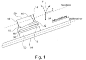
- Fig. 1 shows a side view of the essential assemblies and components of a sighting device 10 for understanding the invention.
- the sighting device 10 can be connected to the weapon 1 by means of an adaptation rail 2.
- the sighting device 10 comprises a housing 12, which in particular converts the components of the reflex sight, parabolic mirror 15 and display 16 as a light source.
- the view is through a disc 13.
- the outlet channel is closed by a neutral filter 14.
- An IR laser illuminator is identified by 17. This is preferably integrated in the housing 12 of the sighting device 10.
- the sighting device 10 also contains electronics 30.
- the reflex sight 50 of the sighting device 10 is usually implemented such that a light source (here micro display 16) is collimated via the mirror 15, preferably in an off-axis parabolic design.
- the mirror 15 is designed such that an interface is provided with a reflective layer which only reflects the light L emitted by the source.
- the other interface is shaped so that transmitted light L T is free from aberrations. In this way, the light from the source is optimally collimated and is superimposed on the incident light that falls through the partially transparent mirror ( Fig. 1a ).
- a target mark 21 can be displayed on the reflex sight 50, but also information such as writing, images and even videos.
- the shape of the target mark 21 can be shown as desired within wide limits by the display 16. A dot, ring or cross shape is preferred.
- variable neutral filter 14 can be used to dim or completely darken the ambient light for the view through the sighting device 10.
- the damping can be set manually or electrically or can be adjusted automatically when using a brightness sensor (not shown in detail). To display the symbols of the virtual sight, the direct view is darkened by the neutral filter 14.
- the sighting device 10 can also be used with a BIV glasses (not shown in detail) without the focus of the glasses having to be changed. Together with the built-in IR laser illuminator 17, night fighting capability is also supported.
- the IR laser illuminator 17 is e.g. by a button 36 on the sighting device 10 on or off.
- the sighting device 10 fulfills the conventional function with a rigid target 21 ( Fig. 2a ).
- the target mark 21 can also be shifted horizontally and vertically in a part of the visual field for ballistic correction.
- angle corrections of the order of +/- 3 ° can be implemented.
- the virtual sight is different, which is suitable for shooting with ammunition with a greatly increased trajectory.
- the target position and actual position of the stopping point of the weapon are represented in the sighting device 10 by symbols which the shooter brings to cover by aiming the weapon.
- the shooter's task is to carry out the aiming and firing in the shortest possible time, since the target information used relates to the time of sighting when the ballistics calculation starts.
- a representation of the target and actual stopping point is shown as an example in 2b to see.
- the weapon is aimed at the target stopping point on the left, ie the symbol of the target stopping point 22, an open cross, and the symbol of the actual stopping point 23, a closed cross, are made to coincide.
- Fig. 2b on the right in addition to the storage of the actual stopping point, the tilting of the weapon due to the inclined position of the actual stopping point 23 shown can also be seen.
- other forms of presentation desired by the user are also possible.
- the sighting device 10 described here is also suitable for shooting in the upper angular group, i.e. with weapon elevations above 45 °.
- the rigid target mark 21 and also the target stopping point 22 are represented in such a way that the viewing direction is parallel to the weapon barrel axis WA when viewed ( Fig. 1 ). This setting is made during the adjustment process, which is described below.
- Fig. 1 the orthogonal right-rotating coordinate system 11 of the sighting device 10 is also shown, the x-axis of which is parallel to the line of sight SL and also parallel to the weapon axis WA, provided that the sighting device is attached and adjusted to the weapon.
- the y-axis lies in the horizontal plane.
- the z-axis is in the plane spanned by the line of sight SL and the perpendicular axis LA.
- the measured values of an inclinometer 31 and a magnetic field sensor 32 are specified with respect to these coordinate axes, although other definitions for the coordinate system would also be possible, if not very practical.
- the electronics 30 of the sighting device contains a processor 33 which essentially carries out the sequence control and the ballistics calculation.
- the ballistic parameters of the ammunition are stored in the processor 33 memory for the weapon used.
- the parameters for various ammunition and weapons can be stored and the desired parameter set can be selected when configuring the sighting device 10.
- Important input variables for the ballistics calculation are the target elevation measured in the sighting device and the target distance.
- the target distance is specified externally or estimated by the shooter and entered as described below. The distance can also be taken over externally via the cable 18 or radio connection 39.
- the ballistics calculation calculates the setpoint of the stop point 22, that is to say both the attachment angle and the side correction angle.
- Other influencing variables on the stopping point such as air temperature, air pressure and wind, can optionally be taken into account.
- the corresponding components of the earth's gravity and the surrounding magnetic field are calculated in the coordinate system 11 of the sighting device 10 and stored as reference values.
- the actual value of the stop point 23 results from the spatial position of the weapon axis WA, which is calculated from the measurements of the earth's gravity and from changes in the magnetic field measurements compared to the spatial position when sighting.
- WA spatial position of the weapon axis
- earth's gravity is also measured as a reference.
- the magnetic field measurement would reveal both the lateral and vertical change in angle in relation to the earth's magnetic field.
- this information alone is usually unsatisfactory.
- the canting can be recognized exactly, but not the changes in angle around the perpendicular axis. Due to the combined evaluation of the surrounding magnetic field and the earth's gravity, a clear determination of the spatial position is possible with a simultaneous reduction of the influence of disturbances.
- the sighting device 10 is preferably operated by a multifunctional rotary switch 35 and a trigger button or key strip with a plurality of buttons 36, which is connected to the sight or the sighting device 10 via a cable.
- the latter can be attached to a suitable location on the weapon.
- other buttons can also be provided on the sighting device 10.
- the display is shown on the display 16 of the sighting device 10.
- the operation is preferably menu-driven. An example should illustrate this:
- the multifunctional rotary switch 35 has on the one hand the function of a push button when the rotary knob is pressed. On the other hand, it has a middle neutral position and at least one left and one right switching point. Starting from the deactivated sighting device 10, this is switched on by pressing the selector switch 35 and this is shown in FIG Fig.
- the trigger button 36 By pressing the trigger button 36 it is entered that the target is sighted and the ballistic calculation for the ammunition used, the elevation of the sight line SL measured in the sighting device 10 and the entered distance is started. The calculated target and actual stopping point 22, 23 of the weapon are shown in the display image 16 of the sighting device 10.
- the sequence control and the calculations are carried out by a ⁇ -processor 33.
- the required parameters and configurations are stored in a non-volatile memory, which can also be a separate EEPROM 34.
- the ballistics calculation determines the necessary corrections for the height and side angle of the weapon axis with respect to the line of sight to the target, taking into account the target distance and the target elevation. For the target stopping point, the components of earth's gravity and the surrounding magnetic field in the coordinate system of the sighting device are calculated, which are set when the weapon axis is aligned.
- the components of the earth's gravity and the surrounding magnetic field are measured in the coordinate system 11 of the sighting device 10. They correspond to the current orientation of the weapon.
- the sighting device 10 is equipped with MEMS sensors for the 3-axis inclination measurement 31 and the 3-axis magnetic field measurement 32.
- the target breakpoint 22 is shown in the center of the image of the display 16.
- the actual stopping point 23 is calculated for the current weapon alignment and is shown offset from the desired stopping point 22 in accordance with the calculated deviations. If the actual stopping point 23 lies outside the image area, it is displayed at the edge of the image in a manner that is suitable for storage.
- the sideways tilt of the weapon is indicated by the inclined position of the symbol for the actual stopping point 23.
- a time symbol shows the shooter whether he is still within a specified time. Since the shooter can see the target object past the sight or the sighting device 10, it is possible for him to recognize a change in the target location, to abort the process and, if necessary, to fire the shot only after a new aiming and aiming process.
- the sighting device 10 is equipped with a laser range finder 4, which measures the distance when aiming at the target. This can be integrated in the sighting device 10 or attached separately to the weapon and connected via a cable 18 or radio connection 39.
- a dynamic lead can also be determined and set.
- the target movement can be identified from at least two measuring sets, consisting of distance, inclination and / or magnetic field measurement, which is then taken into account together with the floor flight time when calculating the target stopping point.
- the time span for the fine adjustment of the weapon can also be included in the result for the target stopping point.
- the power supply to the entire system is preferably implemented using batteries 37.
- a supply from an external source is also possible.
- the sighting device 10 can be used together with a magnifying lens.
- the sighting device 10 must be placed in front of the magnifying optics 3 (e.g. telescopic sight) ( Fig. 5 ).
- the parallel bundle of rays overlaps with the rays of the observed distant object.
- both beams are imaged in the image plane of the telescopic sight 3 and then seen sharply by the shooter at the same time. All representations which the described sighting device 10 enables as such are retained.
- the magnifying target optics 3 can be adjusted parallel to the reflex sight 50 without any aids. To do this, only the reticle of the telescopic sight 3 has to be placed on the target marking 22 of the reflex sight 50. This also applies in the reverse manner if the reflex sight 50 is placed in front of the telescopic sight 3 which has already been adjusted to the weapon.
- a shock sensor 38 is optionally installed, which detects the firing of the shot. This can be used together with the IR laser illuminator 17 for temperature control of programmable ABM (Air Burst Ammunition).
- the shock sensor 38 further enables the function of a shot counter, which indicates to the shooter via the reflex sight (i.e. display 16) the number of ammunition that has been fired and / or still available.
- a display of the loaded type of ammunition is also conceivable.
- the sensors, magnetic field sensors 32 and inclinometers 31 are aligned at the factory with the coordinate system 11 of the sighting device 10. This does not require mechanical fine alignment, but rather knowledge of the installation angle errors, with the knowledge of which the measurements relating to the axes of the coordinate system 11 are converted.
- the installation angle errors are determined during manufacture.
- the installation angle errors are stored in the non-volatile memory of the sighting device 10 and used in the calculations in use.
- the optical axis of the reflex sight 50, i.e. the line of sight SL is mechanically set so that the target point is as possible in the middle of the micro display 16 and runs parallel to the mounting surface.
- the line of sight SL is also the reference for the x-axis of the coordinate system when determining the installation angle errors.
- the fine adjustment of the sighting device 10, i.e. the parallel alignment of the line of sight SL to the weapon axis WA takes place before use on the weapon.
- the weapon axis e.g. the laser beam of a collimator that is inserted into the gun barrel can be used.
- the fine adjustment of the line of sight SL is carried out by shifting the target mark 21 in the image of the display 16.
- the changes in the angle of the line of sight SL which are carried out in relation to the factory setting are determined from the pixel shift and stored. In use, these angle values are used in the calculations in a manner comparable to the installation angle errors.
- the principle of operation of the virtual sight can be easily transferred to riflescopes that already have a display, e.g. thanks to a simple module with the MEMS, the ⁇ processor and the controls, which controls the display in the telescopic sight.
Description
Die Erfindung beschäftigt sich mit einem Reflexvisier mit virtueller Visierung in Form einer einfachen, kleinen und kostengünstigen Visiereinrichtung für Handwaffen zum Verschießen von Munitionen mit gestreckter und überhöhter Flugbahn. Die Visiereinrichtung enthält ein Reflexvisier mit einem Mikro-Display, so dass neben der Zielmarke zusätzlich auch Darstellungen von Text- und Bildinformation möglich sind.The invention is concerned with a reflex sight with virtual sighting in the form of a simple, small and inexpensive sighting device for handguns for firing ammunition with extended and excessive trajectory. The sighting device contains a reflex sight with a micro display, so that in addition to the target mark, text and image information can also be displayed.
Bei Handfeuerwaffen mit Reichweiten von 500m, maximal 1000m werden kleinbauende Reflexvisiere allein oder oft auch in Verbindung mit einem Hauptvisier, z.B. Zielfernrohr, eingesetzt. Diese Reflexvisiere sind gut geeignet für ein treffsicheres Schießen mit Munitionen mit gestreckter Flugbahn. Für das Schießen mit langsamen Granaten, z.B. Verschießen von Granaten mit einem Anbaugerät am Sturmgewehr oder mit einem eigenständigen System, sind diese Visiere wegen der stark überhöhten Flugbahn der Munition zunächst nicht geeignet, weil der Haltepunkt nicht mehr zusammen mit dem Zielobjekt im Sehfeld des Visiers sichtbar dargestellt werden kann. Jedoch kann ein Schütze eine Waffe auch präzise Ausrichten, wenn ihm die Soll-Position und die Ist-Position des Haltepunktes im Visier dargestellt werden.With small arms with ranges of 500m, maximum 1000m, small-scale reflex sights are used alone or often in conjunction with a main sight, e.g. Rifle scope, used. These reflex sights are well suited for accurate shooting with ammunition with a straight trajectory. For shooting with slow grenades, e.g. Shooting grenades with an attachment on the assault rifle or with an independent system, these sights are initially not suitable because of the greatly increased trajectory of the ammunition, because the stopping point can no longer be visibly displayed together with the target object in the field of view of the sight. However, a shooter can also precisely align a weapon if the target position and the actual position of the stopping point are shown to him.
Da während des Richtvorgangs dem Schützen im Visier das Zielobjekt nicht mehr dargestellt wird, sprechen wir in diesem Zusammenhang von einer virtuellen Visierung. Nach dem Anvisieren müssen der Richtvorgang und die Schussabgabe daher in sehr kurzer Zeit erfolgen, da eine Zielbewegung während dieses Vorgangs unberücksichtigt bleibt. Dennoch kann der Schütze an der Visiereinrichtung vorbeisehen und so das Zielobjekt weiterhin beobachten.Since the target object is no longer displayed to the shooter in the sight during the aiming process, we speak of a virtual sight in this context. After sighting, the aiming process and the firing of the shot must therefore take place in a very short time, since a target movement is not taken into account during this process. Nevertheless, the shooter can look past the sighting device and continue to observe the target object.
Mehrere bestehende Lösungsansätze für Visiereinrichtungen zum Schießen von Munitionen mit stark überhöhter Flugbahn zeigen sowohl den Bedarf als auch die Anforderungen an eine gute Lösung für diese Anwendung, wie die nachstehenden Angaben zeigen sollen.Several existing solutions for sighting devices for firing ammunition with a greatly increased trajectory show both the need and the requirements for a good solution for this application, as the information below is intended to show.
Für das Schießen von Granaten mit Handfeuerwaffen sind u.a. einfache opto-mechanische Visiereinrichtungen, wie das Leitervisier oder das Strichplattenvisier, zu nennen. Der Schütze hat hierbei beim Richten die direkte Sicht auf das Ziel. Ein Nachteil ist, dass diese Visiere spezifisch zu Munition und Waffe sind und auch nicht den Gebrauch einer vergrößernden Optik zulassen. Ferner sind sie wegen des erforderlichen Sehfeldes hochbauend.For shooting grenades with handguns, i.a. to name simple opto-mechanical sighting devices, such as the head sight or the reticule sight. The shooter has a direct view of the target when aiming. A disadvantage is that these sights are specific to ammunition and weapons and also do not allow the use of a magnifying lens. Furthermore, they are high-rise because of the required field of view.
Reflexvisiere bzw. Rotpunktvisiere mit verschiebbarem Zielpunkt, wie in
Aus der
Eine andere Lösung sind Visiere mit Direktsicht, welche gegenüber der Waffenachse gedreht werden, wie
Visiereinrichtungen mit virtueller Visierung verlangen nicht das große Sehfeld wie die o.g. Visiereinrichtungen und benötigen auch keine präzise mechanische Einstellung der Zielmarke, da das Positionieren der Zielmarke in der Bilddarstellung des Displays erfolgt. In der
Die
Aus der
Im Gegensatz zu den bisherigen Lösungen liegt der hier beschriebenen Erfindung die Aufgabe zugrunde, eine einfache, kleine und kostengünstige Visiereinrichtung für Handwaffen aufzuzeigen, die sowohl für den gestreckten als auch überhöhten Schuss geeignet ist. Gelöst wird die Aufgabe durch die Merkmale des Patentanspruchs 1. Vorteilhafte Ausgestaltungen werden in den Unteransprüchen aufgeführt.In contrast to the previous solutions, the object of the invention described here is to demonstrate a simple, small and inexpensive sighting device for hand weapons, which is suitable for both extended and excessive firing. The object is achieved by the features of patent claim 1. Advantageous refinements are listed in the subclaims.
Die Erfindung basiert auf der Idee, kleinbauende Reflexvisiere, wie sie für ein treffsicheres Schießen mit Munitionen mit gestreckter Flugbahn verwendet werden, so anzupassen, dass sie auch geeignet sind für das Schießen mit langsamer Munition, wie Granaten, mit stark überhöhter Flugbahn.The invention is based on the idea of adapting small-sized reflex sights, such as those used for accurate shooting with ammunition with a straight trajectory, in such a way that they are also suitable for shooting with slow ammunition, such as grenades, with a greatly inflated trajectory.
Aus der
Die
Dazu wird ein Reflexvisier bevorzugt mit einem Mikro-Display als Lichtquelle ausgestattet. Mit diesem Display können dann neben der Zielmarke auch Text- und Bildinformationen dargestellt werden, was eine virtuelle Visierung ermöglicht. Hierbei werden dem Schützen virtuelle Zielmarken, der Soll- und der Ist-Haltepunkt der Waffe dargestellt. Neben der Verwendung der Zielentfernung und der ballistischen Eigenschaften der Munition ist die Messung der Erdgravitation und des umgebenden Magnetfeldes durch MEMS hervorzuheben. Mit diesen Informationen lassen sich der Soll- und Ist-Haltepunkt der Waffe sowie ihre Ablage in der Visierebene berechnen und darstellen.For this purpose, a reflex sight is preferably equipped with a micro display as the light source. With this display, text and image information can then be shown in addition to the target mark, which enables virtual sighting. The shooter is shown virtual targets, the target and the actual stopping point of the weapon. In addition to using the target range and the ballistic properties of the ammunition, the measurement of gravity and the surrounding magnetic field by MEMS should be emphasized. With this information, the target and actual stopping point of the weapon and its placement in the sighting plane can be calculated and displayed.
Die so geschaffene Visiereinrichtung für Handfeuerwaffen ist für den gestreckten Schuss (Sturmgewehr) und für den stark überhöhten Schuss (Granatwerfer als Anbaugerät an das Sturmgewehr oder Granatpistole, etc.) geeignet. Sie übernimmt die Funktion eines standardmäßigen Reflex- oder Rotpunktvisier, wobei nunmehr auch Text- und Bildinformation darstellbar sind. Für die Ballistikrechnung wird die Zielentfernung über eine externe Datenschnittstelle oder manuell eingegeben. Ballistische Kenngrößen (Schusstafel) sind entsprechend der zu verwendenden Munition(en) und Waffe(n) im eingebauten Rechner gespeichert. MEMS-Sensoren, d.h. ein 3-achsiges Inklinometer und ein 3-achsiger Magnetfeldsensor, messen die Orientierung der Visiereinrichtung gegenüber dem erdfesten Koordinatensystem. Diese liefern beim Anvisieren des Ziels die Zielelevation, welche auch zur Berechnung der einzustellenden Waffenrichtwerte verwendet wird. Beim Anrichten / Ausrichten der Waffe dienen die Sensorwerte zur Berechnung der Ablage der Waffenrohrachse vom Haltepunkt. Soll- und Ist-Lage des Haltepunktes werden in der Visiereinrichtung durch Symbole dargestellt und sind durch entsprechendes Richten der Waffe durch den Schützen zur Deckung zu bringen.The sighting device for handguns thus created is suitable for the extended shot (assault rifle) and for the greatly inflated shot (grenade launcher as an attachment to the assault rifle or grenade gun, etc.). It takes over the function of a standard reflex or red dot sight, whereby text and image information can now also be displayed. For the ballistic calculation, the target distance is entered via an external data interface or manually. Ballistic parameters (shot board) are stored in the built-in computer according to the ammunition (s) and weapon (s) to be used. MEMS sensors, i.e. a 3-axis inclinometer and a 3-axis magnetic field sensor measure the orientation of the sighting device in relation to the earth-fixed coordinate system. When aiming at the target, these deliver the target elevation, which is also used to calculate the weapon target values to be set. When aligning / aligning the weapon, the sensor values are used to calculate the offset of the weapon barrel axis from the stopping point. The target and actual position of the stopping point are represented by symbols in the sighting device and are to be brought to cover by the shooter by appropriate aiming of the weapon.
Vorgeschlagen wird somit eine kleine, leichte, kostengünstige Visiereinrichtung, die die Ersttrefferwahrscheinlichkeit mit allen daraus resultierenden Vorteilen, wie hoher Wirksamkeit, weniger Munitionsverbrauch usw., verbessert. Durch Verwendung von MEMS-Sensoren (Micro-Electro-Mechanical Systems) wird die Baugröße der Visiereinrichtung gegenüber herkömmlicher Reflexvisiere nur unwesentlich geändert. Die Visiereinrichtung kann für verschiedene Munitionen verwendet werden. Die Parameter für die Ballistikrechnung können eingeben und bevorzugt gespeichert werden. Die Visiereinrichtung kann als Ersatz für bereits verwendete Reflexvisiere verwendet werden und bedingt so keine zusätzliche Masse an der Waffe. Das Visier enthält keine mechanisch präzise zu bewegenden Teile und muss auch nicht selbst gegenüber der Waffe gedreht werden, um den großen ballistischen Aufsatzwinkel einzustellen. Die Zielmarke wird hier in der Bilddarstellung des Displays verschoben. Das Schießen kann sowohl in der unteren als auch oberen Winkelgruppe erfolgen, was die Möglichkeit des Steilfeuers erlaubt. Neben der Zielentfernung wird auch die Zielerhöhung bei der Berechnung des Soll-Haltepunktes für die Waffe berücksichtigt. Die Visiereinrichtung kann mit einer Nachtsichtbrille verwendet werden, ohne dass der Fokus der Brille auf nahe Objekte angepasst werden muss. Die Visiereinrichtung kann auch zusammen mit einer vergrößernden Zieloptik (Zielfernrohr) verwendet werden. Dazu wird die Visiereinrichtung vor dem Zielfernrohr montiert. Ein integrierter IR-Laserbeleuchter unterstützt ferner den Nachtkampf. Die Voraussetzungen zur optischen Tempierung von ABM (Air Burst Munition) sind ebenfalls gegeben.A small, light, inexpensive sighting device is thus proposed, which improves the first hit probability with all the resulting advantages, such as high effectiveness, less ammunition consumption, etc. By using MEMS sensors (Micro-Electro-Mechanical Systems), the size of the sighting device is only slightly changed compared to conventional reflex sights. The sighting device can be used for various ammunition. The parameters for the ballistics calculation can be entered and preferably saved. The sighting device can be used as a replacement for already used reflex sights and therefore does not require any additional mass on the weapon. The visor does not contain any parts that can be moved mechanically and does not have to be turned in relation to the weapon itself in order to adjust the large ballistic attachment angle. The target mark is shifted here in the image display. Shooting can be done in both the lower and upper angle groups, which allows the possibility of steep fire. In addition to the target distance, the target increase is also taken into account when calculating the target stopping point for the weapon. The sighting device can be used with night vision glasses without having to adjust the focus of the glasses to nearby objects. The sighting device can also be used together with a magnifying sight (telescopic sight). For this purpose, the sighting device is mounted in front of the telescopic sight. An integrated IR laser illuminator also supports night fighting. The requirements for optical temping of ABM (Air Burst Munition) are also given.
Anhand eines Ausführungsbeispiels mit Zeichnung soll die Erfindung näher erläutert werden. Es zeigt:
- Fig. 1
- eine Visiereinrichtung an einer Waffe in einer Seitenansicht,
- Fig. 1a
- einen off-axis Parabolspiegel mit korrigierter konvexer Fläche für eine aberrationsfreie Durchsicht,
- Fig. 2a
- ein Visierbild bei Direktsicht mit starrer Zielmarke,
- Fig. 2b
- eine virtuelle Visierung mit Darstellung des Soll- und Ist-Haltepunktes der Waffe,
- Fig. 3a
- ein Visierbild mit Direktsicht im Untermenü "Einsatz",
- Fig. 3b
- eine Darstellung des "Hauptmenü",
- Fig. 3c
- eine Darstellung des Untermenüs "Entfernungseingabe",
- Fig. 4
- wesentliche Komponenten der Elektronik,
- Fig. 5
- eine Kombination der Visiereinrichtung mit einer vergrößernden Zieloptik.
- Fig. 1
- a sighting device on a weapon in a side view,
- Fig. 1a
- an off-axis parabolic mirror with corrected convex surface for an aberration-free view,
- Fig. 2a
- a visor image with direct vision with a rigid target,
- Fig. 2b
- a virtual sight with representation of the target and actual stopping point of the weapon,
- Fig. 3a
- a visor image with direct view in the "Operation" submenu,
- Fig. 3b
- a representation of the "main menu",
- Fig. 3c
- a representation of the submenu "distance input",
- Fig. 4
- essential components of electronics,
- Fig. 5
- a combination of the sighting device with a magnifying lens.
Die Visiereinrichtung 10 umfasst ein Gehäuse 12, das insbesondere die Komponenten des Reflexvisiers, Parabolspiegel 15 und Display 16 als Lichtquelle umbaut. Der Einblick erfolgt durch eine Scheibe 13. Der Auslasskanal ist durch ein Neutralfilter 14 abgeschlossen. Mit 17 ist ein IR-Laserbeleuchter gekennzeichnet. Dieser ist bevorzugt im Gehäuse 12 der Visiereinrichtung 10 eingebunden. Die Visiereinrichtung 10 enthält zudem eine Elektronik 30.The
Das Reflexvisier 50 der Visiereinrichtung 10 wird üblicherweise so realisiert, dass eine Lichtquelle (hier Mikro-Display 16) über den Spiegel 15, bevorzugt in off-axis parabolischer Ausführung, kollimiert wird. Der Spiegel 15 ist so ausgeführt, dass eine Grenzfläche mit einer reflektierenden Schicht versehen ist, welche nur das von der Quelle emittierte Licht L reflektiert. Die andere Grenzfläche ist so geformt, dass transmittiertes Licht LT frei von Aberrationen ist. So wird das Licht der Quelle optimal kollimiert und überlagert sich mit dem einfallenden Licht, das durch den teildurchlässigen Spiegel fällt (
Mit dem Mikro-Display 16 kann bei dem Reflexvisier 50 nicht nur eine Zielmarke 21 dargestellt werden, sondern auch Informationen wie Schrift, Bilder und sogar Videos. Die Form der Zielmarke 21 kann durch das Display 16 in weiten Grenzen beliebig dargestellt werden. Eine Punkt-, Ring- oder Kreuzform wird aber bevorzugt.With the
Durch den variablen Neutralfilter 14 kann das Umgebungslicht für den Blick durch die Visiereinrichtung 10 gedämpft oder gänzlich abgedunkelt werden. Die Dämpfung kann manuell oder elektrisch eingestellt bzw. bei Verwendung eines Helligkeitssensors (nicht näher dargestellt) automatisch angepasst werden. Für die Darstellung der Symbole der virtuellen Visierung erfolgt eine Abdunkelung der Direktsicht durch den Neutralfilter 14.The variable
Die Visiereinrichtung 10 kann auch mit einer BIV-Brille (nicht näher dargestellt) genutzt werden, ohne dass dabei der Fokus der Brille verändert werden muss. Zusammen mit dem eingebauten IR-Laserbeleuchter 17 wird damit auch die Nachtkampffähigkeit unterstützt. Der IR-Laserbeleuchter 17 wird z.B. durch einen Taster 36 an der Visiereinrichtung 10 ein- oder ausgeschaltet.The
Für das Schießen von Munitionen mit gestreckter Flugbahn erfüllt die Visiereinrichtung 10 die herkömmliche Funktion mit starrer Zielmarke 21 (
Anders ist die virtuelle Visierung, welche für das Schießen mit Munitionen mit stark überhöhter Flugbahn geeignet ist. Hierbei werden Soll-Position und Ist-Position des Haltepunktes der Waffe in der Visiereinrichtung 10 durch Symbole dargestellt, welche der Schütze durch das Richten der Waffe zur Deckung bringt. Aufgabe des Schützen ist es, den Richtvorgang und die Schussabgabe in möglichst kurzer Zeit durchzuführen, da die verwendete Zielinformation sich auf den Zeitpunkt des Anvisierens mit dem Start der Ballistikrechnung bezieht. Eine Darstellung von Soll- und Ist-Haltepunkt ist beispielhaft in
Hervorzuheben ist, dass sich die hier beschriebene Visiereinrichtung 10 auch für das Schießen in der oberen Winkelgruppe, d.h. mit Waffenerhöhungen über 45° eignet.It should be emphasized that the
Die starre Zielmarke 21 und auch der Soll-Haltepunkt 22 werden so dargestellt, dass bei der Betrachtung die Blickrichtung parallel zur Waffen-Rohrachse WA ist (
Die Elektronik 30 der Visiereinrichtung enthält einen Prozessor 33, welcher im Wesentlichen die Ablaufsteuerung und die Ballistikrechnung durchführt. Die ballistischen Parameter der Munition sind für die verwendete Waffe im Speicher des Prozessors 33 abgelegt. Dabei können die Parameter für verschiedene Munitionen und Waffen gespeichert sein und der gewünschte Parametersatz bei der Konfiguration der Visiereinrichtung 10 ausgewählt werden.The
Wichtige Eingabegrößen für die Ballistikrechnung sind die in der Visiereinrichtung gemessene Zielerhöhung sowie die Zielentfernung. Die Zielentfernung wird von Extern vorgegeben oder vom Schützen geschätzt und, wie nachstehend beschrieben, eingegeben. Die Entfernung kann aber auch von Extern über die Kabel- 18 oder Funkanbindung 39 übernommen werden.Important input variables for the ballistics calculation are the target elevation measured in the sighting device and the target distance. The target distance is specified externally or estimated by the shooter and entered as described below. The distance can also be taken over externally via the
Sobald der Schütze das Ziel anvisiert hat, startet er die Ballistikrechnung, welche den Sollwert des Haltepunktes 22, d.h. sowohl den Aufsatzwinkel als auch den Seiten-Korrekturwinkel, berechnet. Weitere Einflussgrößen auf den Haltepunkt, wie Lufttemperatur, Luftdruck und Wind, können optional berücksichtigt werden. Für die Ausrichtung der Waffe auf den Soll-Haltepunkt 22 werden die entsprechenden Komponenten der Erdgravitation und des umgebenden Magnetfeldes im Koordinatensystem 11 der Visiereinrichtung 10 berechnet und als Referenzwerte gespeichert.As soon as the shooter has sighted the target, he starts the ballistics calculation, which calculates the setpoint of the
Der Ist-Wert des Haltepunktes 23 ergibt sich aus der Raumlage der Waffenachse WA, welche aus den Messungen der Erdgravitation und aus Änderungen der Magnetfeldmessungen gegenüber der Raumlage beim Anvisieren berechnet wird. Im Unterschied zu
Die Bedienung der Visiereinrichtung 10 erfolgt vorzugweise durch einen multifunktionalen Drehschalter 35 und eine Triggertaste bzw. Tastenleiste mit mehreren Tastern 36, die über ein Kabel an das Visier bzw. die Visiereinrichtung 10 angeschlossen ist. Letztere lassen sich so an einer passenden Stelle der Waffe anbringen. Zusätzlich können aber auch weitere Taster an der Visiereinrichtung 10 vorgesehen werden. Die Anzeige erfolgt durch das Display 16 der Visiereinrichtung 10. Die Bedienung ist bevorzugt menügeführt. Ein Beispiel soll dies veranschaulichen:
Der multifunktionale Drehschalter 35 hat einerseits die Funktion eines Drucktasters bei Drücken des Drehknebels. Andererseits hat er eine mittlere Neutralstellung und mindestens einen linken und einen rechten Schaltpunkt. Ausgehend von der ausgeschalteten Visiereinrichtung 10 wird diese durch Drücken des Wahlschalters 35 eingeschaltet und es zeigt sich das in
The
Durch Drücken der Triggertaste 36 wird eingegeben, dass das Ziel anvisiert ist und die Ballistikrechnung für die verwendete Munition, die in der Visiereinrichtung 10 gemessene Elevation der Visierlinie SL und die eingegebene Entfernung gestartet wird. Der berechnete Soll- und Ist-Haltepunkt 22, 23 der Waffe werden im Displaybild 16 der Visiereinrichtung 10 dargestellt.By pressing the
Die Ablaufsteuerung und die Berechnungen werden durch einen µ-Prozessor 33 durchgeführt. In einem nichtflüchtigen Speicher, der auch ein separates EEPROM 34 sein kann, sind die erforderlichen Parameter und Konfigurationen gespeichert.The sequence control and the calculations are carried out by a μ-processor 33. The required parameters and configurations are stored in a non-volatile memory, which can also be a
Die Ballistikrechnung ermittelt die erforderlichen Korrekturen für den Höhen und Seitenwinkel der Waffenachse bezüglich der Sichtlinie zum Ziel unter Berücksichtigung der Zielentfernung und der Zielerhöhung. Für den Soll-Haltepunkt werden die Komponenten der Erdgravitation und des umgebenden Magnetfeldes im Koordinatensystem der Visiereinrichtung berechnet, die sich bei der geforderten Ausrichtung der Waffenachse einstellen.The ballistics calculation determines the necessary corrections for the height and side angle of the weapon axis with respect to the line of sight to the target, taking into account the target distance and the target elevation. For the target stopping point, the components of earth's gravity and the surrounding magnetic field in the coordinate system of the sighting device are calculated, which are set when the weapon axis is aligned.
Für den Ist-Haltepunkt 23 werden die Komponenten der Erdgravitation und des umgebenden Magnetfeldes im Koordinatensystem 11 der Visiereinrichtung 10 gemessen. Sie entsprechen der aktuellen Ausrichtung der Waffe. Hierzu ist die Visiereinrichtung 10 mit MEMS-Sensoren für die 3-achsige Neigungsmessung 31 und die 3-achsige Magnetfeldmessung 32 ausgestattet.For the actual stopping
Der Soll-Haltepunkt 22 wird in der Bildmitte des Displays 16 dargestellt. Der Ist-Haltpunkt 23 wird für die aktuelle Waffenausrichtung berechnet und entsprechend der berechneten Abweichungen versetzt zum Soll-Haltepunkt 22 dargestellt. Sollte der Ist-Haltepunkt 23 außerhalb der Bildfläche liegen, wird er ablagegerecht am Bildrand dargestellt. Die seitliche Verkantung der Waffe wird durch die Schräglage des Symbols für den Ist-Haltepunkt 23 angezeigt.The
Aufgabe des Schützen ist es, die Waffe schnell auf den Soll-Haltepunkt 22 zu bringen und den Schuss abzugeben. Da während der virtuellen Visierung der zuletzt erkannte Zielort eingefroren ist, ist es wichtig, dass nur wenig Zeit für das Feinausrichten der Waffe benötigt wird. Ein Zeitsymbol zeigt dem Schützen an, ob er noch in einer vorgegebenen Zeit liegt. Da der Schütze am Visier bzw. der Visiereinrichtung 10 vorbei das Zielobjekt sehen kann, ist es ihm möglich, eine Änderung des Zielortes zu erkennen, den Vorgang abzubrechen und den Schuss ggf. erst nach einem erneuten Ziel- und Richtvorgang abzugeben.It is the shooter's task to quickly bring the weapon to the
In einer weiteren Ausbaustufe ist die Visiereinrichtung 10 mit einem Laser- Entfernungsmesser 4 ausgestattet, der beim Anvisieren des Zieles die Entfernung misst. Dieser kann in der Visiereinrichtung 10 integriert sein oder aber separat an der Waffe angebracht und über eine Kabel- 18 oder Funkanbindung 39 angeschlossen sein.In a further expansion stage, the
Bei Verwendung eines integrierten Laser-Entfernungsmessers 4 kann auch ein dynamischer Vorhalt ermittelt und eingestellt werden. Aus mindestens zwei Messsätzen, bestehend aus Entfernungs-, Neigungs- und / oder Magnetfeldmessung, kann die Zielbewegung erkannt werden, die danach zusammen mit der Geschossflugzeit bei der Berechnung des Soll-Haltepunktes berücksichtigt wird. Zusätzlich kann auch die Zeitspanne für das Feinausrichten der Waffe in das Ergebnis für den Soll-Haltepunkt einfließen.When using an integrated laser rangefinder 4, a dynamic lead can also be determined and set. The target movement can be identified from at least two measuring sets, consisting of distance, inclination and / or magnetic field measurement, which is then taken into account together with the floor flight time when calculating the target stopping point. In addition, the time span for the fine adjustment of the weapon can also be included in the result for the target stopping point.
Die Stromversorgung des Gesamtsystems wird bevorzugt über Batterien 37 realisiert. Eine Speisung durch eine externe Quelle ist aber auch möglich.The power supply to the entire system is preferably implemented using
Einen Überblick über die wesentlichen und bereits erwähnten Komponenten der Elektronik gibt
Ein weiterer Vorteil der Visiereinrichtung 10 ist, dass sie zusammen mit einer vergrößernden Optik eingesetzt werden kann. Dazu muss die Visiereinrichtung 10 vor der vergrößernde Zieloptik 3 (z.B. Zielfernrohr) platziert sein (
Des Weiteren kann die vergrößernde Zieloptik 3 (Zielfernrohr) ohne Hilfsmittel zu dem Reflexvisier 50 parallel justiert werden. Dazu muss nur das Absehen des Zielfernrohrs 3 auf die Zielmarkierung 22 des Reflexvisiers 50 gestellt werden. Dies gilt in umgekehrter Weise ebenso, wenn das Reflexvisier 50 vor das bereits zur Waffe justierte Zielfernrohr 3 gesetzt wird.Furthermore, the magnifying target optics 3 (telescopic sight) can be adjusted parallel to the
Optional ist ein Schocksensor 38 eingebaut, der die Schussabgabe erkennt. Dieser kann zusammen mit dem IR-Laserbeleuchter 17 zur Tempierung von programmierbarer ABM (Air Burst Munition) verwendet werden. Der Schocksensor 38 ermöglicht des Weiteren die Funktion eines Schusszählers, welche dem Schützen über das Reflexvisier (d.h. Display 16) die Zahl der verschossenen und / oder noch verfügbaren Munition anzeigt. Eine Anzeige der geladenen Munitionsart ist ebenfalls denkbar.A
Die Sensoren, Magnetfeldsensoren 32 und Inklinometer 31, werden werkseitig auf das Koordinatensystem 11 der Visiereinrichtung 10 ausgerichtet. Hierzu bedarf es nicht der mechanischen Feinausrichtung, sondern der Kenntnis der Einbauwinkelfehler, mit deren Kenntnis die Messungen bezüglich der Achsen des Koordinatensystems 11 umgerechnet werden. Die Ermittlung der Einbauwinkelfehler erfolgt bei der Herstellung. Die Einbauwinkelfehler werden im nichtflüchtigen Speicher der Visiereinrichtung 10 gespeichert und im Einsatz bei den Berechnungen verwendet. Die optische Achse des Reflexvisiers 50, d.h. die Sichtlinie SL, ist mechanisch so eingestellt, dass der Zielpunkt möglichst in der Mitte des Mikro-Displays 16 liegt und parallel zur Montagefläche verläuft. Die Sichtlinie SL ist auch die Referenz für die x-Achse des Koordinatensystems bei der Ermittlung der Einbauwinkelfehler.The sensors,
Die Feinjustage der Visiereinrichtung 10, d.h. die Parallelausrichtung der Sichtlinie SL zur Waffenachse WA, erfolgt vor dem Einsatz an der Waffe. Dabei kann als Referenz für die Waffenachse z.B. der Laserstrahl eines Kollimators, der in den Waffenlauf gesteckt wird, verwendet werden. Die Feineinstellung der Sichtlinie SL erfolgt durch Verschiebung der Zielmarke 21 im Bild des Displays 16. Die dabei vorgenommen Winkeländerungen der Sichtlinie SL gegenüber der Werkseinstellung werden aus der Pixelverschiebung ermittelt und gespeichert. Im Einsatz werden diese Winkelwerte vergleichbar den Einbauwinkelfehlern bei den Berechnungen verwendet.The fine adjustment of the
Das Funktionsprinzip der virtuellen Visierung lässt sich einfach auf Zielfernrohre, die bereit eine Displayeinblendung besitzen, übertragen, z.B. durch ein einfaches Modul mit den MEMS, dem µ-Prozessor und den Bedienelementen, welches das Display im Zielfernrohr ansteuert.The principle of operation of the virtual sight can be easily transferred to riflescopes that already have a display, e.g. thanks to a simple module with the MEMS, the µ processor and the controls, which controls the display in the telescopic sight.
Claims (11)
- Sighting device (10) for handguns with a reflector sight, comprising a reflector sight, which is incorporated as a light source, with a micro-display (16), and a three-axis inclination sensor and a three-axis magnetic field sensor, the measurement signals of which are used for determining the spatial position of the sighting device (10), wherein the reflector sight provides the direct view for the extended shot, and virtual sighting in the case of a highly elevated shot takes place by displaying symbols for the desired and actual point of aim of the weapon axis in the micro-display (16),
wherein
the sighting device (10) is configured such that the desired point of aim (22) of the weapon is calculated from a distance from target and an elevation of target for the ammunition used, and
the sighting device (10) is configured such that the actual point of aim of the weapon axis is calculated from the determined spatial position of the sighting device, and
the sighting device (10) is configured such that the offset of the actual point of aim (23) is calculated from the desired point of aim (22) of the weapon axis and is displayed on the display (16). - Sighting device (10) according to Claim 1, characterized in that the distance to the target is input externally, manually or via a data interface which is a cable interface (18) and/or a radio interface (39), and/or a laser rangefinder (4) is incorporated.
- Sighting device (10) according to one of Claims 1 and 2, characterized in that additionally the tilting of the weapon is ascertained and displayed on the display (16) .
- Sighting device (10) according to one of Claims 1 to 3, characterized in that the brightness of the light source is variable.
- Sighting device (10) according to one of Claims 1 to 4, characterized by a variable neutral density filter (14) for dimming the direct view.
- Sighting device (10) according to one of Claims 1 to 5, characterized in that a separate strip of keys (36) having at least one key is present for control purposes, which strip of keys can be connected to the sighting device (10) via the cable interface (18) and/or via the radio interface (39), wherein operation is menu-controlled.
- Sighting device (10) according to one of Claims 1 to 6, characterized in that the sighting device (10) contains an IR diode laser (17) for illumination purposes and for signal transmission.
- Sighting device (10) according to one of Claims 1 to 7, characterized by a shock sensor (38) for shot detection.
- Sighting device (10) according to one of Claims 1 to 8 having night-vision goggles, wherein the focus of the night-vision goggles does not have to be further adjusted for close targets.
- Sighting device (10) according to one of Claims 1 to 9 with a zooming aiming optical system (3), wherein the sighting device (10) is positioned in front of the zooming aiming optical system (3).
- Weapon having a sighting device (10) according to one of Claims 1 to 10.
Applications Claiming Priority (2)
| Application Number | Priority Date | Filing Date | Title |
|---|---|---|---|
| DE102013019281.1A DE102013019281A1 (en) | 2013-11-19 | 2013-11-19 | Reflex sight with virtual sight |
| PCT/EP2014/074927 WO2015075036A1 (en) | 2013-11-19 | 2014-11-18 | Reflector sight having virtual sighting |
Publications (2)
| Publication Number | Publication Date |
|---|---|
| EP3071921A1 EP3071921A1 (en) | 2016-09-28 |
| EP3071921B1 true EP3071921B1 (en) | 2020-01-01 |
Family
ID=51982542
Family Applications (1)
| Application Number | Title | Priority Date | Filing Date |
|---|---|---|---|
| EP14802848.3A Active EP3071921B1 (en) | 2013-11-19 | 2014-11-18 | Reflector sight having virtual sighting |
Country Status (5)
| Country | Link |
|---|---|
| EP (1) | EP3071921B1 (en) |
| DE (1) | DE102013019281A1 (en) |
| DK (1) | DK3071921T3 (en) |
| LT (1) | LT3071921T (en) |
| WO (1) | WO2015075036A1 (en) |
Cited By (1)
| Publication number | Priority date | Publication date | Assignee | Title |
|---|---|---|---|---|
| US11486677B2 (en) | 2021-01-07 | 2022-11-01 | Israel Weapon Industries (I.W.I) Ltd. | Grenade launcher aiming control system |
Families Citing this family (7)
| Publication number | Priority date | Publication date | Assignee | Title |
|---|---|---|---|---|
| AT519642B1 (en) | 2015-01-20 | 2019-01-15 | Leupold & Stevens Inc | Real-time ballistic solutions for calculating a target match and specifying a subsonic threshold |
| US10415933B1 (en) | 2015-01-20 | 2019-09-17 | Leupold & Stevens, Inc. | Real-time ballistic solutions for moving-target aiming calculations |
| RU2613767C2 (en) * | 2015-06-25 | 2017-03-21 | Публичное акционерное общество "Красногорский завод им. С.А. Зверева" | Commander sighting and surveillance complex |
| BE1024403B1 (en) * | 2016-07-15 | 2018-02-14 | Fn Herstal S.A. | Aiming system |
| SG10201606547WA (en) | 2016-08-08 | 2018-03-28 | Advanced Mat Engineering Pte Ltd | Wearable Programming Unit For Deploying Air Burst Munition |
| US11287638B2 (en) | 2019-08-20 | 2022-03-29 | Francesco E. DeAngelis | Reflex sight with superluminescent micro-display, dynamic reticle, and metadata overlay |
| FR3120938B1 (en) * | 2021-03-22 | 2023-09-08 | Thales Sa | METHOD FOR ASSISTING SHOOTING AT A MOVING TARGET, ASSOCIATED DEVICE AND ASSEMBLY |
Family Cites Families (13)
| Publication number | Priority date | Publication date | Assignee | Title |
|---|---|---|---|---|
| DE3048534C2 (en) | 1980-12-22 | 1983-02-03 | Messerschmitt-Bölkow-Blohm GmbH, 8000 München | "Reflex sight" |
| US5824942A (en) * | 1996-01-22 | 1998-10-20 | Raytheon Company | Method and device for fire control of a high apogee trajectory weapon |
| US5920995A (en) * | 1997-12-08 | 1999-07-13 | Sammut; Dennis J. | Gunsight and reticle therefor |
| US7296358B1 (en) * | 2004-01-21 | 2007-11-20 | Murphy Patrick J | Digital vertical level indicator for improving the aim of projectile launching devices |
| US7225578B2 (en) | 2005-01-06 | 2007-06-05 | Eotech Acquisition Corp. | Aiming sight having fixed light emitting diode (LED) array and rotatable collimator |
| DE102005007910A1 (en) | 2005-02-08 | 2006-08-10 | Carl Zeiss Optronics Gmbh | Firearm for long flight duration projectiles has fire guidance system with target data acquisition and adjusters for sight tube on weapon |
| US9557140B2 (en) * | 2008-01-24 | 2017-01-31 | Aimpoint Ab | Sight |
| DE102009033567A1 (en) | 2009-07-16 | 2011-01-27 | Rheinmetall Soldier Electronics Gmbh | Fire control device for a handgun |
| US8166698B2 (en) * | 2009-08-13 | 2012-05-01 | Roni Raviv | Reflex sight for weapon |
| IT1401016B1 (en) | 2010-07-12 | 2013-07-05 | Selex Galileo Spa | OPTOELECTRONIC DIGITAL APPARATUS TO ASSIST A OPERATOR IN DETERMINING THE SHOE STRUCTURE TO BE ATTACHED TO A PORTABLE GRENADE LAUNCHER TO HIT A TARGET IN MOVEMENT, AND ITS FUNCTIONING METHOD. |
| WO2012061154A1 (en) * | 2010-10-25 | 2012-05-10 | Banc3, Inc. | Weapon sight |
| US8474173B2 (en) * | 2010-10-28 | 2013-07-02 | Surefire, Llc | Sight system |
| IL212109A0 (en) * | 2011-04-03 | 2011-06-30 | Ipu Ind Ltd | Firearm gun-sight |
-
2013
- 2013-11-19 DE DE102013019281.1A patent/DE102013019281A1/en active Pending
-
2014
- 2014-11-18 WO PCT/EP2014/074927 patent/WO2015075036A1/en active Application Filing
- 2014-11-18 LT LTEP14802848.3T patent/LT3071921T/en unknown
- 2014-11-18 DK DK14802848.3T patent/DK3071921T3/en active
- 2014-11-18 EP EP14802848.3A patent/EP3071921B1/en active Active
Non-Patent Citations (1)
| Title |
|---|
| None * |
Cited By (1)
| Publication number | Priority date | Publication date | Assignee | Title |
|---|---|---|---|---|
| US11486677B2 (en) | 2021-01-07 | 2022-11-01 | Israel Weapon Industries (I.W.I) Ltd. | Grenade launcher aiming control system |
Also Published As
| Publication number | Publication date |
|---|---|
| WO2015075036A1 (en) | 2015-05-28 |
| DK3071921T3 (en) | 2020-03-30 |
| EP3071921A1 (en) | 2016-09-28 |
| LT3071921T (en) | 2020-05-11 |
| DE102013019281A1 (en) | 2015-05-21 |
Similar Documents
| Publication | Publication Date | Title |
|---|---|---|
| EP3071921B1 (en) | Reflector sight having virtual sighting | |
| KR102652020B1 (en) | Observation optical device with integrated display system | |
| US8074394B2 (en) | Riflescope with image stabilization | |
| US11402175B2 (en) | Optical system with cant indication | |
| US20150247702A1 (en) | Feedback display for riflescope | |
| EP2878913B1 (en) | Fire control sight, handgun with such a fire control sigth and a method for aiming said handgun | |
| DE102012003124B3 (en) | Optical observation device for target acquisition and route guidance | |
| EP2286172B1 (en) | Combination sight | |
| US11287638B2 (en) | Reflex sight with superluminescent micro-display, dynamic reticle, and metadata overlay | |
| AT518962B1 (en) | Long-range optical device with a reticle | |
| WO2006097310A1 (en) | Sighting mechanism for fire arms | |
| DE19719977C1 (en) | Video viewing-sight with integrated weapon control system for gun | |
| DE102018133064A1 (en) | Ballistic target system with digital adjustment wheel | |
| CN113446901B (en) | Dual focal plane reticle for optical sighting device | |
| EP2781874A2 (en) | Telescopic sight | |
| DE202017007134U1 (en) | Systems, circuits, components, devices, devices, assemblies and computer-executable code for aiming a firearm | |
| DE3325755A1 (en) | Night-combat aiming aid for anti-tank hand weapons | |
| EP3303976B1 (en) | Combination gun sight with single eyepoint | |
| DE102008015423A1 (en) | Visor with objective viewpoint e.g. for weapons with ammunition for flight paths, involves having sight line straightening at target against running axis by vertical or horizontal tilting | |
| EP3042143B1 (en) | Handgun having aiming means | |
| DE102013015324A1 (en) | Device for enhancing aiming accuracy of hand-held weapon, has laser or electronic camera adapted to upstream micro channel plate for temporal association of image data supplied from camera by pulse-modulated square wave | |
| DE102016123778B4 (en) | Accessory part with cant indicator for an optical system | |
| BR112021014084A2 (en) | OPTICAL VIEW ELEMENT WITH TRIGGER COUNTER SYSTEM | |
| DE102014103539A1 (en) | Remote optical device | |
| RO120015B1 (en) | Passive-type apparatus for night aiming |
Legal Events
| Date | Code | Title | Description |
|---|---|---|---|
| PUAI | Public reference made under article 153(3) epc to a published international application that has entered the european phase |
Free format text: ORIGINAL CODE: 0009012 |
|
| 17P | Request for examination filed |
Effective date: 20160419 |
|
| AK | Designated contracting states |
Kind code of ref document: A1 Designated state(s): AL AT BE BG CH CY CZ DE DK EE ES FI FR GB GR HR HU IE IS IT LI LT LU LV MC MK MT NL NO PL PT RO RS SE SI SK SM TR |
|
| AX | Request for extension of the european patent |
Extension state: BA ME |
|
| DAX | Request for extension of the european patent (deleted) | ||
| STAA | Information on the status of an ep patent application or granted ep patent |
Free format text: STATUS: EXAMINATION IS IN PROGRESS |
|
| 17Q | First examination report despatched |
Effective date: 20180507 |
|
| GRAP | Despatch of communication of intention to grant a patent |
Free format text: ORIGINAL CODE: EPIDOSNIGR1 |
|
| STAA | Information on the status of an ep patent application or granted ep patent |
Free format text: STATUS: GRANT OF PATENT IS INTENDED |
|
| RIC1 | Information provided on ipc code assigned before grant |
Ipc: F41G 3/16 20060101ALI20190712BHEP Ipc: F41G 1/48 20060101ALI20190712BHEP Ipc: F41G 3/06 20060101AFI20190712BHEP Ipc: F41G 1/30 20060101ALI20190712BHEP Ipc: F41G 1/473 20060101ALI20190712BHEP |
|
| INTG | Intention to grant announced |
Effective date: 20190731 |
|
| GRAS | Grant fee paid |
Free format text: ORIGINAL CODE: EPIDOSNIGR3 |
|
| GRAA | (expected) grant |
Free format text: ORIGINAL CODE: 0009210 |
|
| STAA | Information on the status of an ep patent application or granted ep patent |
Free format text: STATUS: THE PATENT HAS BEEN GRANTED |
|
| AK | Designated contracting states |
Kind code of ref document: B1 Designated state(s): AL AT BE BG CH CY CZ DE DK EE ES FI FR GB GR HR HU IE IS IT LI LT LU LV MC MK MT NL NO PL PT RO RS SE SI SK SM TR |
|
| REG | Reference to a national code |
Ref country code: GB Ref legal event code: FG4D Free format text: NOT ENGLISH |
|
| REG | Reference to a national code |
Ref country code: CH Ref legal event code: EP Ref country code: AT Ref legal event code: REF Ref document number: 1220287 Country of ref document: AT Kind code of ref document: T Effective date: 20200115 |
|
| REG | Reference to a national code |
Ref country code: DE Ref legal event code: R096 Ref document number: 502014013400 Country of ref document: DE |
|
| REG | Reference to a national code |
Ref country code: IE Ref legal event code: FG4D Free format text: LANGUAGE OF EP DOCUMENT: GERMAN |
|
| REG | Reference to a national code |
Ref country code: FI Ref legal event code: FGE |
|
| REG | Reference to a national code |
Ref country code: DK Ref legal event code: T3 Effective date: 20200326 |
|
| REG | Reference to a national code |
Ref country code: SE Ref legal event code: TRGR |
|
| REG | Reference to a national code |
Ref country code: NO Ref legal event code: CREP Representative=s name: BARBARE DIETRICH C/O THUL PATENTANWALTSGESELLSCHAFT MBH |
|
| REG | Reference to a national code |
Ref country code: CH Ref legal event code: NV Representative=s name: WEINMANN ZIMMERLI, CH Ref country code: NL Ref legal event code: FP |
|
| REG | Reference to a national code |
Ref country code: NO Ref legal event code: T2 Effective date: 20200101 |
|
| PG25 | Lapsed in a contracting state [announced via postgrant information from national office to epo] |
Ref country code: PT Free format text: LAPSE BECAUSE OF FAILURE TO SUBMIT A TRANSLATION OF THE DESCRIPTION OR TO PAY THE FEE WITHIN THE PRESCRIBED TIME-LIMIT Effective date: 20200527 Ref country code: CZ Free format text: LAPSE BECAUSE OF FAILURE TO SUBMIT A TRANSLATION OF THE DESCRIPTION OR TO PAY THE FEE WITHIN THE PRESCRIBED TIME-LIMIT Effective date: 20200101 Ref country code: RS Free format text: LAPSE BECAUSE OF FAILURE TO SUBMIT A TRANSLATION OF THE DESCRIPTION OR TO PAY THE FEE WITHIN THE PRESCRIBED TIME-LIMIT Effective date: 20200101 |
|
| PG25 | Lapsed in a contracting state [announced via postgrant information from national office to epo] |
Ref country code: HR Free format text: LAPSE BECAUSE OF FAILURE TO SUBMIT A TRANSLATION OF THE DESCRIPTION OR TO PAY THE FEE WITHIN THE PRESCRIBED TIME-LIMIT Effective date: 20200101 Ref country code: GR Free format text: LAPSE BECAUSE OF FAILURE TO SUBMIT A TRANSLATION OF THE DESCRIPTION OR TO PAY THE FEE WITHIN THE PRESCRIBED TIME-LIMIT Effective date: 20200402 Ref country code: LV Free format text: LAPSE BECAUSE OF FAILURE TO SUBMIT A TRANSLATION OF THE DESCRIPTION OR TO PAY THE FEE WITHIN THE PRESCRIBED TIME-LIMIT Effective date: 20200101 Ref country code: IS Free format text: LAPSE BECAUSE OF FAILURE TO SUBMIT A TRANSLATION OF THE DESCRIPTION OR TO PAY THE FEE WITHIN THE PRESCRIBED TIME-LIMIT Effective date: 20200501 |
|
| REG | Reference to a national code |
Ref country code: DE Ref legal event code: R097 Ref document number: 502014013400 Country of ref document: DE |
|
| PG25 | Lapsed in a contracting state [announced via postgrant information from national office to epo] |
Ref country code: ES Free format text: LAPSE BECAUSE OF FAILURE TO SUBMIT A TRANSLATION OF THE DESCRIPTION OR TO PAY THE FEE WITHIN THE PRESCRIBED TIME-LIMIT Effective date: 20200101 Ref country code: RO Free format text: LAPSE BECAUSE OF FAILURE TO SUBMIT A TRANSLATION OF THE DESCRIPTION OR TO PAY THE FEE WITHIN THE PRESCRIBED TIME-LIMIT Effective date: 20200101 Ref country code: EE Free format text: LAPSE BECAUSE OF FAILURE TO SUBMIT A TRANSLATION OF THE DESCRIPTION OR TO PAY THE FEE WITHIN THE PRESCRIBED TIME-LIMIT Effective date: 20200101 Ref country code: SM Free format text: LAPSE BECAUSE OF FAILURE TO SUBMIT A TRANSLATION OF THE DESCRIPTION OR TO PAY THE FEE WITHIN THE PRESCRIBED TIME-LIMIT Effective date: 20200101 Ref country code: SK Free format text: LAPSE BECAUSE OF FAILURE TO SUBMIT A TRANSLATION OF THE DESCRIPTION OR TO PAY THE FEE WITHIN THE PRESCRIBED TIME-LIMIT Effective date: 20200101 |
|
| PLBE | No opposition filed within time limit |
Free format text: ORIGINAL CODE: 0009261 |
|
| STAA | Information on the status of an ep patent application or granted ep patent |
Free format text: STATUS: NO OPPOSITION FILED WITHIN TIME LIMIT |
|
| 26N | No opposition filed |
Effective date: 20201002 |
|
| PG25 | Lapsed in a contracting state [announced via postgrant information from national office to epo] |
Ref country code: IT Free format text: LAPSE BECAUSE OF FAILURE TO SUBMIT A TRANSLATION OF THE DESCRIPTION OR TO PAY THE FEE WITHIN THE PRESCRIBED TIME-LIMIT Effective date: 20200101 |
|
| PG25 | Lapsed in a contracting state [announced via postgrant information from national office to epo] |
Ref country code: PL Free format text: LAPSE BECAUSE OF FAILURE TO SUBMIT A TRANSLATION OF THE DESCRIPTION OR TO PAY THE FEE WITHIN THE PRESCRIBED TIME-LIMIT Effective date: 20200101 Ref country code: SI Free format text: LAPSE BECAUSE OF FAILURE TO SUBMIT A TRANSLATION OF THE DESCRIPTION OR TO PAY THE FEE WITHIN THE PRESCRIBED TIME-LIMIT Effective date: 20200101 |
|
| PG25 | Lapsed in a contracting state [announced via postgrant information from national office to epo] |
Ref country code: MC Free format text: LAPSE BECAUSE OF FAILURE TO SUBMIT A TRANSLATION OF THE DESCRIPTION OR TO PAY THE FEE WITHIN THE PRESCRIBED TIME-LIMIT Effective date: 20200101 |
|
| PG25 | Lapsed in a contracting state [announced via postgrant information from national office to epo] |
Ref country code: LU Free format text: LAPSE BECAUSE OF NON-PAYMENT OF DUE FEES Effective date: 20201118 |
|
| PG25 | Lapsed in a contracting state [announced via postgrant information from national office to epo] |
Ref country code: IE Free format text: LAPSE BECAUSE OF NON-PAYMENT OF DUE FEES Effective date: 20201118 |
|
| REG | Reference to a national code |
Ref country code: DE Ref legal event code: R082 Ref document number: 502014013400 Country of ref document: DE Representative=s name: HUEBSCH, KIRSCHNER & PARTNER, PATENTANWAELTE U, DE |
|
| PG25 | Lapsed in a contracting state [announced via postgrant information from national office to epo] |
Ref country code: TR Free format text: LAPSE BECAUSE OF FAILURE TO SUBMIT A TRANSLATION OF THE DESCRIPTION OR TO PAY THE FEE WITHIN THE PRESCRIBED TIME-LIMIT Effective date: 20200101 Ref country code: MT Free format text: LAPSE BECAUSE OF FAILURE TO SUBMIT A TRANSLATION OF THE DESCRIPTION OR TO PAY THE FEE WITHIN THE PRESCRIBED TIME-LIMIT Effective date: 20200101 Ref country code: CY Free format text: LAPSE BECAUSE OF FAILURE TO SUBMIT A TRANSLATION OF THE DESCRIPTION OR TO PAY THE FEE WITHIN THE PRESCRIBED TIME-LIMIT Effective date: 20200101 |
|
| PG25 | Lapsed in a contracting state [announced via postgrant information from national office to epo] |
Ref country code: MK Free format text: LAPSE BECAUSE OF FAILURE TO SUBMIT A TRANSLATION OF THE DESCRIPTION OR TO PAY THE FEE WITHIN THE PRESCRIBED TIME-LIMIT Effective date: 20200101 Ref country code: AL Free format text: LAPSE BECAUSE OF FAILURE TO SUBMIT A TRANSLATION OF THE DESCRIPTION OR TO PAY THE FEE WITHIN THE PRESCRIBED TIME-LIMIT Effective date: 20200101 |
|
| REG | Reference to a national code |
Ref country code: NO Ref legal event code: CREP Representative=s name: RWS, EUROPA HOUSE, CHILTERN PARK, CHILTERN HILL, SL99FG |
|
| PGFP | Annual fee paid to national office [announced via postgrant information from national office to epo] |
Ref country code: BE Payment date: 20221118 Year of fee payment: 9 |
|
| PGFP | Annual fee paid to national office [announced via postgrant information from national office to epo] |
Ref country code: NL Payment date: 20231120 Year of fee payment: 10 |
|
| PGFP | Annual fee paid to national office [announced via postgrant information from national office to epo] |
Ref country code: GB Payment date: 20231123 Year of fee payment: 10 |
|
| PGFP | Annual fee paid to national office [announced via postgrant information from national office to epo] |
Ref country code: SE Payment date: 20231120 Year of fee payment: 10 Ref country code: NO Payment date: 20231124 Year of fee payment: 10 Ref country code: LT Payment date: 20231023 Year of fee payment: 10 Ref country code: FR Payment date: 20231120 Year of fee payment: 10 Ref country code: FI Payment date: 20231121 Year of fee payment: 10 Ref country code: DK Payment date: 20231124 Year of fee payment: 10 Ref country code: DE Payment date: 20231121 Year of fee payment: 10 Ref country code: CH Payment date: 20231201 Year of fee payment: 10 Ref country code: BG Payment date: 20231120 Year of fee payment: 10 Ref country code: AT Payment date: 20231121 Year of fee payment: 10 |
|
| PGFP | Annual fee paid to national office [announced via postgrant information from national office to epo] |
Ref country code: BE Payment date: 20231120 Year of fee payment: 10 |