EP3071362B1 - Laser cutting head with a cooling unit fixed to the head ; laser cutting and/or punching machine tool with such laser cutting head - Google Patents
Laser cutting head with a cooling unit fixed to the head ; laser cutting and/or punching machine tool with such laser cutting head Download PDFInfo
- Publication number
- EP3071362B1 EP3071362B1 EP14809305.7A EP14809305A EP3071362B1 EP 3071362 B1 EP3071362 B1 EP 3071362B1 EP 14809305 A EP14809305 A EP 14809305A EP 3071362 B1 EP3071362 B1 EP 3071362B1
- Authority
- EP
- European Patent Office
- Prior art keywords
- laser cutting
- cutting head
- focusing
- laser
- cooling unit
- Prior art date
- Legal status (The legal status is an assumption and is not a legal conclusion. Google has not performed a legal analysis and makes no representation as to the accuracy of the status listed.)
- Active
Links
- 238000003698 laser cutting Methods 0.000 title claims description 79
- 238000001816 cooling Methods 0.000 title claims description 72
- 238000004080 punching Methods 0.000 title claims description 4
- 238000005520 cutting process Methods 0.000 claims description 28
- 239000000463 material Substances 0.000 claims description 24
- 230000017525 heat dissipation Effects 0.000 claims description 21
- 230000003287 optical effect Effects 0.000 claims description 17
- 230000005540 biological transmission Effects 0.000 claims description 8
- 239000012809 cooling fluid Substances 0.000 claims description 5
- 239000007789 gas Substances 0.000 description 10
- 239000002184 metal Substances 0.000 description 10
- 229910052751 metal Inorganic materials 0.000 description 10
- 239000013307 optical fiber Substances 0.000 description 8
- 238000012546 transfer Methods 0.000 description 7
- 229910000838 Al alloy Inorganic materials 0.000 description 6
- 239000000835 fiber Substances 0.000 description 5
- 229910001369 Brass Inorganic materials 0.000 description 4
- 239000010951 brass Substances 0.000 description 4
- 238000013021 overheating Methods 0.000 description 4
- 239000004065 semiconductor Substances 0.000 description 4
- 239000000853 adhesive Substances 0.000 description 3
- 230000001070 adhesive effect Effects 0.000 description 3
- 239000012141 concentrate Substances 0.000 description 3
- 230000004927 fusion Effects 0.000 description 3
- 239000010410 layer Substances 0.000 description 3
- 230000002035 prolonged effect Effects 0.000 description 3
- 230000001681 protective effect Effects 0.000 description 3
- IJGRMHOSHXDMSA-UHFFFAOYSA-N Atomic nitrogen Chemical compound N#N IJGRMHOSHXDMSA-UHFFFAOYSA-N 0.000 description 2
- RYGMFSIKBFXOCR-UHFFFAOYSA-N Copper Chemical compound [Cu] RYGMFSIKBFXOCR-UHFFFAOYSA-N 0.000 description 2
- 229910052802 copper Inorganic materials 0.000 description 2
- 239000010949 copper Substances 0.000 description 2
- 238000009792 diffusion process Methods 0.000 description 2
- 238000009826 distribution Methods 0.000 description 2
- 238000000605 extraction Methods 0.000 description 2
- 230000001678 irradiating effect Effects 0.000 description 2
- 238000012423 maintenance Methods 0.000 description 2
- 238000000034 method Methods 0.000 description 2
- 230000003134 recirculating effect Effects 0.000 description 2
- OKTJSMMVPCPJKN-UHFFFAOYSA-N Carbon Chemical compound [C] OKTJSMMVPCPJKN-UHFFFAOYSA-N 0.000 description 1
- UGFAIRIUMAVXCW-UHFFFAOYSA-N Carbon monoxide Chemical compound [O+]#[C-] UGFAIRIUMAVXCW-UHFFFAOYSA-N 0.000 description 1
- 238000010521 absorption reaction Methods 0.000 description 1
- 229910002091 carbon monoxide Inorganic materials 0.000 description 1
- 239000011248 coating agent Substances 0.000 description 1
- 238000000576 coating method Methods 0.000 description 1
- 230000001427 coherent effect Effects 0.000 description 1
- 238000010276 construction Methods 0.000 description 1
- 238000012937 correction Methods 0.000 description 1
- 230000006866 deterioration Effects 0.000 description 1
- 230000000694 effects Effects 0.000 description 1
- 239000011521 glass Substances 0.000 description 1
- 229910002804 graphite Inorganic materials 0.000 description 1
- 239000010439 graphite Substances 0.000 description 1
- 238000010438 heat treatment Methods 0.000 description 1
- 230000001788 irregular Effects 0.000 description 1
- 238000003754 machining Methods 0.000 description 1
- 239000000155 melt Substances 0.000 description 1
- 239000007769 metal material Substances 0.000 description 1
- 150000002739 metals Chemical class 0.000 description 1
- 238000001393 microlithography Methods 0.000 description 1
- 229910052757 nitrogen Inorganic materials 0.000 description 1
- 239000002245 particle Substances 0.000 description 1
- 238000012545 processing Methods 0.000 description 1
- 239000011241 protective layer Substances 0.000 description 1
- 239000000758 substrate Substances 0.000 description 1
- 238000009834 vaporization Methods 0.000 description 1
- 230000008016 vaporization Effects 0.000 description 1
- 238000003466 welding Methods 0.000 description 1
Images


Classifications
-
- B—PERFORMING OPERATIONS; TRANSPORTING
- B23—MACHINE TOOLS; METAL-WORKING NOT OTHERWISE PROVIDED FOR
- B23K—SOLDERING OR UNSOLDERING; WELDING; CLADDING OR PLATING BY SOLDERING OR WELDING; CUTTING BY APPLYING HEAT LOCALLY, e.g. FLAME CUTTING; WORKING BY LASER BEAM
- B23K26/00—Working by laser beam, e.g. welding, cutting or boring
- B23K26/36—Removing material
- B23K26/38—Removing material by boring or cutting
-
- B—PERFORMING OPERATIONS; TRANSPORTING
- B23—MACHINE TOOLS; METAL-WORKING NOT OTHERWISE PROVIDED FOR
- B23K—SOLDERING OR UNSOLDERING; WELDING; CLADDING OR PLATING BY SOLDERING OR WELDING; CUTTING BY APPLYING HEAT LOCALLY, e.g. FLAME CUTTING; WORKING BY LASER BEAM
- B23K26/00—Working by laser beam, e.g. welding, cutting or boring
- B23K26/02—Positioning or observing the workpiece, e.g. with respect to the point of impact; Aligning, aiming or focusing the laser beam
- B23K26/04—Automatically aligning, aiming or focusing the laser beam, e.g. using the back-scattered light
- B23K26/046—Automatically focusing the laser beam
-
- B—PERFORMING OPERATIONS; TRANSPORTING
- B23—MACHINE TOOLS; METAL-WORKING NOT OTHERWISE PROVIDED FOR
- B23K—SOLDERING OR UNSOLDERING; WELDING; CLADDING OR PLATING BY SOLDERING OR WELDING; CUTTING BY APPLYING HEAT LOCALLY, e.g. FLAME CUTTING; WORKING BY LASER BEAM
- B23K26/00—Working by laser beam, e.g. welding, cutting or boring
- B23K26/02—Positioning or observing the workpiece, e.g. with respect to the point of impact; Aligning, aiming or focusing the laser beam
- B23K26/06—Shaping the laser beam, e.g. by masks or multi-focusing
- B23K26/064—Shaping the laser beam, e.g. by masks or multi-focusing by means of optical elements, e.g. lenses, mirrors or prisms
- B23K26/0648—Shaping the laser beam, e.g. by masks or multi-focusing by means of optical elements, e.g. lenses, mirrors or prisms comprising lenses
-
- B—PERFORMING OPERATIONS; TRANSPORTING
- B23—MACHINE TOOLS; METAL-WORKING NOT OTHERWISE PROVIDED FOR
- B23K—SOLDERING OR UNSOLDERING; WELDING; CLADDING OR PLATING BY SOLDERING OR WELDING; CUTTING BY APPLYING HEAT LOCALLY, e.g. FLAME CUTTING; WORKING BY LASER BEAM
- B23K26/00—Working by laser beam, e.g. welding, cutting or boring
- B23K26/08—Devices involving relative movement between laser beam and workpiece
-
- B—PERFORMING OPERATIONS; TRANSPORTING
- B23—MACHINE TOOLS; METAL-WORKING NOT OTHERWISE PROVIDED FOR
- B23K—SOLDERING OR UNSOLDERING; WELDING; CLADDING OR PLATING BY SOLDERING OR WELDING; CUTTING BY APPLYING HEAT LOCALLY, e.g. FLAME CUTTING; WORKING BY LASER BEAM
- B23K26/00—Working by laser beam, e.g. welding, cutting or boring
- B23K26/14—Working by laser beam, e.g. welding, cutting or boring using a fluid stream, e.g. a jet of gas, in conjunction with the laser beam; Nozzles therefor
- B23K26/1462—Nozzles; Features related to nozzles
-
- B—PERFORMING OPERATIONS; TRANSPORTING
- B23—MACHINE TOOLS; METAL-WORKING NOT OTHERWISE PROVIDED FOR
- B23K—SOLDERING OR UNSOLDERING; WELDING; CLADDING OR PLATING BY SOLDERING OR WELDING; CUTTING BY APPLYING HEAT LOCALLY, e.g. FLAME CUTTING; WORKING BY LASER BEAM
- B23K26/00—Working by laser beam, e.g. welding, cutting or boring
- B23K26/70—Auxiliary operations or equipment
- B23K26/702—Auxiliary equipment
- B23K26/703—Cooling arrangements
-
- B—PERFORMING OPERATIONS; TRANSPORTING
- B23—MACHINE TOOLS; METAL-WORKING NOT OTHERWISE PROVIDED FOR
- B23K—SOLDERING OR UNSOLDERING; WELDING; CLADDING OR PLATING BY SOLDERING OR WELDING; CUTTING BY APPLYING HEAT LOCALLY, e.g. FLAME CUTTING; WORKING BY LASER BEAM
- B23K26/00—Working by laser beam, e.g. welding, cutting or boring
- B23K26/70—Auxiliary operations or equipment
- B23K26/702—Auxiliary equipment
- B23K26/707—Auxiliary equipment for monitoring laser beam transmission optics
-
- G—PHYSICS
- G03—PHOTOGRAPHY; CINEMATOGRAPHY; ANALOGOUS TECHNIQUES USING WAVES OTHER THAN OPTICAL WAVES; ELECTROGRAPHY; HOLOGRAPHY
- G03B—APPARATUS OR ARRANGEMENTS FOR TAKING PHOTOGRAPHS OR FOR PROJECTING OR VIEWING THEM; APPARATUS OR ARRANGEMENTS EMPLOYING ANALOGOUS TECHNIQUES USING WAVES OTHER THAN OPTICAL WAVES; ACCESSORIES THEREFOR
- G03B30/00—Camera modules comprising integrated lens units and imaging units, specially adapted for being embedded in other devices, e.g. mobile phones or vehicles
Definitions
- the present invention relates to laser cutting devices for cutting machine tools and in particular relates to a laser cutting head according to the preamble of claim 1 (see, for example, WO2012/157355 A1 ), to be used in a fiber optic laser cutting system in a cutting/punching machine tool for sheet metal.
- a laser device emits a coherent, monochrome ray of light, concentrated in a rectilinear beam having extremely high luminosity (brilliance), by means of a stimulated emission process.
- the possibility of concentrating a large amount of energy in a very small point enables laser devices to cut, engrave and weld metals.
- the cutting of metallic material typically occurs by vaporization and, particularly, by fusion. In this last case the laser beam melts a small point of the metal and the molten metal (dross) is removed by a blast or jet of gas.
- laser source can be used to generate a light beam suitable for cutting metal.
- gas dioxide, carbon monoxide, CO2
- solid-state lasers are used.
- the laser beam is focused on the workpieces by a laser cutting head, or focusing head, that is connected to the emission apparatus by an optical chain (in CO2 lasers) or a transmission fiber (optical fiber, for example in YAG diode lasers). Because of its reduced dimensions and weight, the laser cutting head can, in fact, be moved with precision and speed by the machine tool in order to cut the workpiece.
- the latter typically comprises an optical collimator which converges the light beam leaving the optical fiber on a focusing unit capable of focusing the collimated laser beam on the workpiece to be cut.
- the focused laser beam leaves the focusing head through a cutting nozzle which concentrates the blast or jet of gas used to remove the dross generated by the fusion of the metal and limits the probability of the dross reaching the focusing unit.
- the focusing unit allows concentrating the laser beam, i.e. positioning the focal point or focus thereof on a given point on the surface of the workpiece to cut or immediately underneath this surface.
- the focusing unit typically comprises a focusing lens mounted on a lens-holder slide or carriage that is movable along an adjustment direction that is parallel to the direction of the laser beam so that the latter can be focused. More precisely, the lens-holder slide is moved by a respective actuator which is controlled according to a distance between the cutting head and the surface of the workpiece, said distance being measured by a suitable sensor that is mounted on the cutting head.
- the surface of the workpiece (a large sheet of metal, for example) is, in fact, generally irregular, not flat, curved.
- the focusing lens and the relative lens-holder slide are housed inside a hermetically closed container or casing so as to prevent the entry of contaminating and extraneous elements that could dirty the lens and thus alters the optical characteristics thereof.
- Cooling systems are provided to cool the cutting head and, in particular, the focusing lens.
- thermo focus shift makes impossible for the cutting system to focus the laser beam in the desired optimal point on the surface of the workpiece, and determines a consequent deterioration in the cutting characteristics to the point of it being impossible to make the cut at all.
- the temperature increase may also damage the protective layer that is generally provided on the surfaces of the lenses and thus causes a further variation of the optical characteristics of the lenses.
- External cooling of the casing containing the focusing unit is not, in fact, sufficient to guarantee an adequate cooling of the focusing lens.
- cooling systems using a gas flow have the drawback of requiring the use of expensive gases that are devoid of contaminating elements. Contaminating or extraneous particles or elements contained in the gas may deposit on the focusing lens, causing not only a variation of the refraction index of the optics, but also an absorption of the energy of the laser beam and hence a reduction in the power available for cutting.
- JP 2012091191 discloses a laser machining apparatus that includes a laser emitting unit provided with laser generating means for generating a laser beam, a laser head provided with galvano scanners for emitting the laser beam outputted from the laser emitting unit to a workpiece, and an optical fiber cable for transmitting the laser beam from the laser emitting unit to the laser head.
- the optical fiber cable is provided with a head connector attached detachably on the laser head.
- the head connector is provided with a beam expander that includes a diffusion lens for diffusing the laser beam emitted from the optical fiber cable and a convergent lens for making the laser beam emitted from the diffusion lens converge as a parallel beam.
- US 20080030823 discloses a method and device for focusing a laser beam outputted from a laser oscillator through a lens and irradiating an object.
- the device comprises mirrors for reflecting the laser beam outputted from the laser oscillator and a condenser lens for focusing the laser beam and irradiating the object. Because a focal distance of the condenser lens can change due to a change in temperature, when irradiation of the laser beam is restarted after the irradiation has stopped, the lens tube containing the condenser lens is heated or cooled by a temperature control device provided with a Peltier device.
- US 6198579 discloses an objective with optical elements, particularly lens, for a projection exposure device used in semiconductor microlithography.
- the objective is provided with a cooling device for the correction of image errors due to the heating effects in the optical elements, in particular due to non-rotationally-symmetrical temperature distributions in the optical elements.
- the cooling device comprises several Peltier elements that are arranged on at least one of the optical elements, distributed over its periphery, and are differently driven electrically in order to act on the temperature distribution in the optical element.
- a further object is to obtain a laser cutting head provided with a cooling system having a simple and economic construction and effective and reliable operation.
- Still another object is to provide a laser cutting head allowing maintaining the focus of the laser beam in a fixed position, even after prolonged and intensive use.
- a laser cutting head is provided as defined in claim 1.
- Other preferred embodiments of this laser cutting head are defined in claims 2 to 12.
- a laser cutting and/or punching machine tool comprising such a laser cutting head is defined in claim 13.
- the laser cutting head according to this aspect of the invention can be fed by a laser emission apparatus using optical transmission means and can be associated with a cutting machine tool.
- the laser cutting head comprises collimation means to collimate a laser beam generated by the emission apparatus, focusing means to focus the collimated laser beam leaving the collimation means and a casing to house and contain the focusing means provided with a focusing lens and with supporting means for housing the focusing lens and moving the latter along an adjustment direction in order to change the focal point of the laser beam emitted.
- the laser cutting head includes a cooling unit, which is externally associated to the casing and is provided with one or more Peltier cell and a heat dissipation element, and thermal conductive connecting means arranged for connecting the supporting means to the cooling unit in order to rigidly link said supporting means and said cooling unit and to extract by heat conduction from the supporting means and the focusing lens the heat generated by the laser beam when passing through the focusing lens.
- the supporting means and the thermal conductive connecting means are made of a thermal conductivity material, preferably a high thermal conductivity material.
- the laser cutting head further includes a moving element that supports the thermal conductive connecting means and the cooling unit and is slidably coupled to an external wall of the casing, movable along the adjustment direction so as to move the supporting means and the focusing means for adjusting the focal point of the laser beam.
- the thermal conductive connecting means comprises a first connecting element and a second connecting element, both of which are made of a thermal conductivity material, wherein the first connecting element has a first end fixed to, and holding, the supporting means and a second end fixed to the second connecting element, which is connected to the cold side of the Peltier cell.
- the hot side of the Peltier cell is connected to the heat dissipation element.
- the heat generated in the focusing lens by the passage of the laser beam is transferred and transmitted by the supporting means and thermal conductive connecting means to the Peltier cell, which is suitably powered and controlled by direct or PWM (pulse-width modulation) electric current and transfers this heat to the heat dissipation element.
- PWM pulse-width modulation
- the thermal conductive connecting means and the moving element make possible both to control the temperature of the focusing lens (by means of the Peltier cell) and to move the supporting means and the focusing lens (together with the cooling unit) along the adjustment direction in order to adjust the focal point of the laser beam.
- a laser cutting head is provided as defined in claim 13.
- the laser cutting head can be fed by a laser emission apparatus using optical transmission means and can be associated with a cutting machine tool.
- the laser cutting head comprises collimation means to collimate a laser beam generated by the emission apparatus, focusing means to focus the collimated laser beam leaving the collimation means and a casing to house and contain the focusing means provided with a focusing lens and with supporting means for housing the focusing lens and move the latter along an adjustment direction in order to change the focal point of the laser beam emitted.
- the laser cutting head comprises a cooling unit, which is externally fixed to the casing and provided with one or more Peltier cell, and a heat dissipation element and thermal conductive connecting means arranged for connecting the supporting means to the cooling unit in order to extract by heat conduction from the supporting means and the focusing lens the heat generated by the laser beam when passing through the focusing lens.
- the supporting means and the thermal conductive connecting means are made of a thermal conductivity material, preferably a high thermal conductivity material.
- the thermal conductive connecting means comprises at least one flexible thermal conductive element that is connected to the cold side of the Peltier cell, whereas the heat dissipation element is connected to the hot side of the Peltier cell.
- the heat generated in the focusing lens by the passage of the laser beam is transferred and transmitted by the supporting element and thermal conductive connecting means to the Peltier cell, which is suitably powered and controlled by direct or PWM (pulse-width modulation) electric current and transfers this heat to the heat dissipation element.
- the Peltier cell which works as a heat pump, by removing heat allows the temperature of the focusing lens to be controlled and, in particular, prevents the latter from overheating, which would result in a variation in its refraction index and thus an uncontrolled focal shift.
- the supporting means and the focusing lens can be effectively cooled by the Peltier cell while they freely move along the adjustment direction inside the casing for adjusting the focal point of the laser beam.
- the thermal efficiency of the cooling system of the laser cutting head disclosed in the present invention is comparable to that of the known gas cooling systems which remove heat from the lens by convection.
- the laser cutting head of the invention prevents the phenomenon of "thermal focus shift" of the focusing lens during the operation, even prolonged and intensive, allowing the laser beam to be focused on the desired optimal point with respect to the surface of the workpiece, ensuring efficient and accurate cutting. Temperature control and adjustment also prevents damage to the protective superficial layer of the focusing lens.
- a laser cutting head 1 is shown according to a first embodiment of the invention, which is arranged to be powered by a laser emission apparatus, of a known type and not shown in the figures, by means of optical transmission means and associable with a cutting machine tool.
- the emission apparatus is of solid-state laser stimulated emission type
- the optical transmission means comprises an optical fiber cable suitable for conveying the laser beam generated by the emission apparatus to the laser cutting head 1.
- the laser cutting head 1 comprises collimation means 2 for collimating the laser beam generated by the laser emission apparatus, focusing means 5 for focusing the collimated laser beam leaving the collimation means 2 and a casing 4 for containing and housing the focusing means 5.
- the laser cutting head 1 also comprises a cutting nozzle 18, that is fixed to the casing 4 by an optical centering ring-nut 19 and through which the focused laser beam comes out.
- the cutting nozzle 18 concentrates a blast or jet of gas for removing the dross generated by the fusion of the workpiece and at the same time limits the probability of this dross reaching the inside of the casing 4 and the focusing means 5.
- the collimation means 2 are of known type and comprises a set of lenses and a mirror capable of converging and collimating the laser beam coming from the optical fiber in a rectilinear laser beam directed towards the focusing means 5.
- the focusing means comprises at least one focusing lens 5.
- the laser cutting head 1 further includes supporting means 6 that is arranged to receive and hold the focusing lens 5 and is movable along an adjustment direction X inside the casing 4 to allow adjusting the focal point or focus of the laser beam coming out from the focusing lens 5.
- the supporting means includes a supporting element 6, which substantially acts as a carriage or slide for the focusing lens 5 and is housed inside a cavity 21 of the casing 4 wherein is slidably moved along the adjustment direction X by driving means 9.
- the driving means 9 includes, for example, a linear electric actuator or a recirculating ball screw operated by a rotary electric motor and coupled to the relative lead screw that is connected to the supporting element 6.
- the driving means 9 is fixed to the casing 4 and is connected to the supporting element 6 through an opening carried out in a side wall 4b of the casing 4.
- the supporting element 6 comprises a seat 7 suitable for receiving and locking the focusing lens 5.
- the laser cutting head 1 further comprises a cooling unit 10, which is externally fixed to the casing 4 and thermal conductive connecting means 11 arranged for connecting the supporting means 6 to the cooling unit 10 so as to extract by heat conduction from the supporting element 6 and the focusing lens 5 the heat that is generated by the laser beam when the latter passes through said focusing lens 5.
- the supporting element 6 is made of a thermal conductivity material, preferably a high thermal conductivity material such as aluminium alloy or brass, in order to allow the heat to be transferred from the focusing lens 5.
- the thermal conductive connecting means 11 comprises at least one flexible thermal conductive element made of high thermal conductivity material, for example a braided copper tape and/or graphite-coated tape.
- the flexible thermal conductive element 11 comprises a main portion 11a, which is fixed to the cooling unit 10 and from which two elongated portions 11b depart that are secured to opposite sides of supporting element 6.
- the flexible thermal conductive element 11 may comprise a single elongated portion 11b in addition to the main portion 11a.
- the flexibility of the thermal conductive element 11 in no way hinders the movement of the supporting element 6 along the adjustment direction X during operation of the laser cutting head 1 while the thermal conductivity material of the thermal conductive element 11 ensure an optimal heat extraction from the focusing lens 5.
- the cooling unit 10 comprises at least one Peltier cell 12 and a heat dissipation element 13.
- the flexible thermal conductive device 11 is connected to the cold side 12a of the Peltier cell 12, whereas the heat dissipation element 13 is connected to the hot side 12b of the Peltier cell 12.
- the Peltier cell is a thermoelectric device that acts as a solid-state heat pump and typically has the appearance of a thin plate: one of the two sides or faces of the plate absorbs heat while the other emits the heat. The direction in which the heat is transferred depends on the direction of the direct current applied at the ends of this plate. More precisely, a Peltier cell is composed of a plurality of Peltier junctions arranged in series to form a thin plate. The junction is formed of two doped semi-conductors, one N-type and one P-type, connected together by two opposing sheets of copper that form the outside faces or sides of the plate.
- the Peltier cell 12 used in the cooling unit 10 is of a known type.
- the laser head 1 comprises a cover 16 made of thermal conductivity material, preferably a high thermal conductivity material such as aluminium alloy or brass, to close an opening 17 of the casing 4 that gives access to the cavity 21 in which the supporting element 6 and the focusing lens 5 move.
- a cover 16 made of thermal conductivity material, preferably a high thermal conductivity material such as aluminium alloy or brass, to close an opening 17 of the casing 4 that gives access to the cavity 21 in which the supporting element 6 and the focusing lens 5 move.
- the cold side 12a of the Peltier cell 12 is fixed to an outer wall of the cover 16 and the flexible thermal conductive element 11 is fixed to the inner wall of the cover 16.
- the flexible thermal conductive element 11 can be directly fixed to the cold side 12a of the Peltier cell through a corresponding opening provided in the cover 16 ( figures 4-7 ).
- the cold side 12a of the Peltier cell 12 can be fixed to an external wall 4a, for example a front wall, of the casing 4 and the flexible thermal conductive element 11 can be directly fixed to the cold side 12a through a corresponding opening which is provided in the casing 4 and gives access to the cavity 21.
- the cooling unit 10 comprises a plurality of Peltier cells 12 arranged in series and/or parallel.
- the heat dissipation element 13 comprises a body made of high thermal conductivity material, such as aluminium alloy, provided with a plurality of cooling ducts 14 that allow the passage of air, in particular by convection, in order to cool the body itself.
- the heat dissipation element 13 has a parallelepiped shape and has a plurality of cooling ducts 14 arranged side by side and extending along a longitudinal direction, for example parallel to the adjustment direction X.
- the hot side 12b of the Peltier cell 12 is fixed to a rear wall of the heat dissipation element 13.
- Thermally conductive adhesives can be used to fix the thermal conductive connecting means 11 to the supporting means 6 and to the Peltier cell 12. More precisely, thermally conductive adhesives are used to fix the thermal conductive connecting means 11 to the supporting element 6 and to the cover 16 and/or to the cold side 12a of the Peltier cell and to fix the opposite sides 12a, 12b of the Peltier cell to the cover 16 and to the heat dissipation element 13.
- FIGS 8 to 11 show a version of the cooling unit 10 which comprises intake means 15 arranged for introducing a cooling fluid inside said cooling ducts 14 in order to increase the heat exchange (forced convection) and to cool the hot side 12b of the Peltier cell more quickly and effectively.
- the intake means 15 includes, for instance, a couple of nozzles supplied with compressed air and capable of introducing said compressed air into the cooling ducts 14.
- a diverter element 20 allows the flow of compressed air coming out from the nozzles 15 to be directed in the cooling ducts 14 so that the cooling fluid, i.e. the compressed air, leaves the heat exchange element 13 directed toward the workpiece.
- the heat generated in the focusing lens 5 by the passage of the laser beam coming out from the collimation means 3 (heat generated by the non-absolute transparency of the lens) is transferred and transmitted to the supporting element 6, to the thermal conductive connecting means 11 and to the cold side 12a of the Peltier cell 12.
- the heat is transferred from the focusing lens 5 to the Peltier cell 12, which transfer the heat to the heat dissipation element 13 (fixed to the hot side 12b of said Peltier cell 12).
- the focusing lens 5 transfers heat to the supporting element 6, which transfers heat to the flexible thermal conductive element 11.
- the heat extraction operated by the Peltier cell 12, which works as a heat pump, allows to control the temperature of the focusing lens 5 and in particular to prevent the overheating of the lens 5 with consequent variation of the lens refractive index and hence a focus shift.
- the laser cutting head 1 of the invention during operation, even long and intensive, allows to avoid thermal focus shift of the focusing lens 5 and therefore to focus the laser beam in the desired and optimal point with respect to the surface of the workpiece with cutting accuracy and efficiency.
- the temperature control and adjustment allows avoiding damage of the protective superficial layer of the focusing lens 5.
- the supporting means and the focusing lens can be effectively cooled by the Peltier cell while they move along the adjustment direction inside the casing for adjusting the focal point of the laser beam.
- the thermal efficiency of the cooling system of the laser cutting head disclosed in the present invention is comparable to that of the known gas cooling systems which remove heat from the lens by convection.
- a laser cutting head 1 is shown according to a second embodiment of the invention, which is arranged to be powered by a laser emission apparatus by means of optical transmission means and is associable with a cutting machine tool.
- the laser cutting head 1 comprises collimation means 2 for collimating the laser beam generated by the laser emission apparatus, focusing means 5 for focusing the collimated laser beam leaving the collimation means 2 and a casing 4 for containing and housing the focusing means 5.
- the laser cutting head 1 also comprises a cutting nozzle 18, that is fixed to the casing 4 for example by a ring-nut 19 and through which the focused laser beam comes out.
- the collimation means 2 are of known type and may comprise a set of lenses capable of converging and collimating the laser beam coming from the optical transmission means in a rectilinear laser beam.
- a mirror can be provided for redirecting the laser beam towards the focusing means 5 that comprises at least one focusing lens 5.
- the laser cutting head 1 comprises supporting means 6 arranged for receiving and holding said focusing lens 5 within a cavity 21 of said casing 4 and movable along an adjustment direction X so as to change a focal point or focus of the said laser beam coming out from said focusing means 5.
- the cavity 21 is provided with an accessing opening 17.
- the supporting means includes a supporting element 6 that is provided with a seat 7 suitable for receiving and holding the focusing lens 5.
- the laser cutting head 1 further includes according to the present invention a cooling unit 10, which is externally associated to the casing 4 and is provided with at least one Peltier cell 12 and a heat dissipation element 13, and thermal conductive connecting means 31 which is arranged for connecting the supporting means 6 to the cooling unit 10 so as to rigidly link said supporting means 6 and said cooling unit 10 and to extract by heat conduction from the supporting element 6 and the focusing lens 5 the heat that is generated by the laser beam passing through said focusing lens 5.
- the supporting element 6 is made of a thermal conductivity material, preferably a high thermal conductivity material such as aluminium alloy or brass.
- the Peltier cell 12 comprises a cold side 12a that is connected to the thermal conductive connecting means 31, 32 and a hot side 12b that is connected to the heat dissipation element 13.
- the heat dissipation element 13 has a body made of high thermal conductivity material, such as aluminium alloy, and is provided with a plurality of cooling ducts 14 that allow the passage of air, in particular by natural or forced convection, to cool the body itself.
- the cooling unit 10 may also comprise a plurality of Peltier cells 12 arranged in parallel and/or in series.
- the laser cutting head 1 includes a moving element 37 that supports the thermal conductive connecting means 31 and/or the cooling unit 10 and is slidably coupled to an external wall 4a, for example the front wall, of the casing 4 and is movable along the adjustment direction X so as to move the supporting means 6 and the focusing means 5.
- Driving means 9 is fixed to the casing 4 and coupled to the moving element 37 so as to move the latter along said adjustment direction X.
- the thermal conductive connecting means comprises a first connecting element 31 and a second connecting element 32 both made of a thermal conductivity material, preferably a high thermal conductivity material such as aluminium alloy or brass.
- the first connecting element 31 is provided with a first end fixed to, and holding, the supporting element 6 and a second end fixed to the second connecting element 32, the latter being connected to the Peltier cell 12, in particular to a cold side 12a thereof.
- the first connecting element 31 is shaped substantially as an elongated bracket or arm which is connected to the second connecting element 32, for example detachably by suitable fastening means.
- the first connecting element 31 and second connecting element 32 can be also made integral.
- the second connecting element 32 has a flat shape with an inner surface to which the first connecting element 31 is fastened and an external surface which is connected to the cold side 12a of the Peltier cell 12.
- the flat shape and the dimensions of the second connecting element 32 allow an efficient and high thermal exchange between the thermal conductive connecting means 31, 32 (together with the supporting element 6 and the focusing lens 5) and the Peltier cell 12.
- Thermally conductive adhesives can be used to mutually fix the external surface of the second connecting element 32 and the cold side 12a of the Peltier cell 12.
- the moving element 37 is coupled to the second connecting element 32 so as to move the latter together with the first connecting element 31, the supporting element 6 and the focusing lens 5 and the cooling unit 10.
- the moving element 37 can directly support the cooling unit 10 and the latter can support the supporting element 6 and the focusing lens 5 by means of the connecting elements 31, 32.
- the moving element 37 comprises a flat element that is slidably coupled to the external wall 4a, i.e. a front wall, of the casing 4 and is provided with a respective opening 37a that gives access to the cavity 21 of the casing 4. More precisely, the opening 37a of the moving element 37 allows the connecting elements 31, 32 to rigidly connect the cooling unit 10 to the supporting element 6.
- the moving element 37 has a linking arm 38 that is coupled to the driving means 9.
- the latter is fixed to a side wall 4b of the casing 4 and includes for example, a linear electric actuator or a recirculating ball screw operated by a rotary electric motor and connected to the relative lead screw fastened to the linking arm 38.
- the heat generated in the focusing lens 5 by the passage of the laser beam coming out from the collimation means 2 (heat generated by the non-absolute transparency of lens) is transferred and transmitted to the supporting element 6, to the thermal conductive connecting means 31, 32 and then to the cold side 12a of the Peltier cell 12. Then the Peltier cell 12 transfers the heat of the focusing lens to the heat dissipation element 13 that is fixed to the hot side 12b.
- the Peltier cell 12 allows controlling the temperature of the focusing lens 5 and in particular to prevent the overheating of the focusing lens 5 with consequent variation of the lens refractive index and hence a focus shift.
- the intensity and voltage of the direct or PWD (pulse-width modulation) electrical current, which powers the Peltier cell 12 it is possible to control the temperature of the focusing lens 5 in an accurate and reliable manner.
- the laser cutting head 1 of the invention during operation, even long and intensive, allows to avoid thermal focus shift of the focusing lens 5 and therefore to focus the laser beam in the desired and optimum point with respect to the surface of the work piece with cutting accuracy and efficiency.
- the temperature control and adjustment can help to prevent damage of the protective superficial layer of the focusing lens 5.
- thermal conductive connecting means and the moving element make possible both to control the temperature of the focusing lens (by means of the Peltier cell) and to move the supporting means and the focusing lens along the adjustment direction in order to adjust the focal point of the laser beam.
- connecting elements 31, 32 can be disconnected from the moving element 37 allowing to easily and quickly remove from the laser cutting head 1 both the cooling unit 10 and the supporting element 6 with the focusing lens 5, for maintenance and/or controls.
- Figures 15 to 17 show a variant of the laser cutting head 1, which differs from the second embodiment of figure 12 to 14 and above described for the different thermal conductive connecting means 41, 42 and the moving element 47.
- the second connecting element 42 of the thermal conductive connecting means and the moving element 47 are mutually fixed so as to form a flat shaped element of which an inner surface is coupled to the first connecting element 41 of the thermal conductive connecting means and an external surface is connected to the cold side 12a of the Peltier cell.
- the second connecting element 42 and the moving element 47 can be also made integral and in a high thermal conductivity material.
- the moving element 47 has a linking arm 48 that is coupled to the driving means 9.
- FIG 18 shows another variant of the laser cutting head 1 of the invention, wherein the cooling unit 10 further comprises intake means 15 arranged for introducing a cooling fluid inside said cooling ducts 14 of the heat dissipation element 13 in order to increase the heat exchange (forced convection) and to cool the hot side 12b of the Peltier cell more quickly and effectively.
- the intake means 15 includes, for instance, a couple of nozzles supplied with compressed air and capable of introducing the said expanded air in the cooling ducts 14.
- a diverter element 20 allows the flow of compressed air coming out from the nozzles 15 to be directed in the cooling ducts 14 so that the cooling fluid, that is the air, leaves the heat exchange element 13.
Description
- The present invention relates to laser cutting devices for cutting machine tools and in particular relates to a laser cutting head according to the preamble of claim 1 (see, for example,
WO2012/157355 A1 ), to be used in a fiber optic laser cutting system in a cutting/punching machine tool for sheet metal. - The use of laser systems for cutting, engraving and welding parts is well known and widely diffused in the field of machine tools for processing metal sheets and plates.
- A laser device emits a coherent, monochrome ray of light, concentrated in a rectilinear beam having extremely high luminosity (brilliance), by means of a stimulated emission process. The possibility of concentrating a large amount of energy in a very small point enables laser devices to cut, engrave and weld metals. The cutting of metallic material typically occurs by vaporization and, particularly, by fusion. In this last case the laser beam melts a small point of the metal and the molten metal (dross) is removed by a blast or jet of gas.
- Different types of laser source can be used to generate a light beam suitable for cutting metal. Typically, gas (dioxide, carbon monoxide, CO2) and solid-state (diode, doped glass, fiber) lasers are used.
- In machine tools, due to the high energy levels required to cut sheet metal, and particularly thick sheet metal, dimensions and weight of the laser emission apparatus are such as to prevent them from being positioned on the machine. The laser beam is focused on the workpieces by a laser cutting head, or focusing head, that is connected to the emission apparatus by an optical chain (in CO2 lasers) or a transmission fiber (optical fiber, for example in YAG diode lasers). Because of its reduced dimensions and weight, the laser cutting head can, in fact, be moved with precision and speed by the machine tool in order to cut the workpiece.
- In so-called fiber laser cutting systems, where a cable of optical fiber is used to transport the laser beam to the cutting head, the latter typically comprises an optical collimator which converges the light beam leaving the optical fiber on a focusing unit capable of focusing the collimated laser beam on the workpiece to be cut.
- The focused laser beam leaves the focusing head through a cutting nozzle which concentrates the blast or jet of gas used to remove the dross generated by the fusion of the metal and limits the probability of the dross reaching the focusing unit. The focusing unit allows concentrating the laser beam, i.e. positioning the focal point or focus thereof on a given point on the surface of the workpiece to cut or immediately underneath this surface.
- Correct positioning of the focal point is necessary to concentrate the full power of the laser beam and correctly cut the material.
- The focusing unit typically comprises a focusing lens mounted on a lens-holder slide or carriage that is movable along an adjustment direction that is parallel to the direction of the laser beam so that the latter can be focused. More precisely, the lens-holder slide is moved by a respective actuator which is controlled according to a distance between the cutting head and the surface of the workpiece, said distance being measured by a suitable sensor that is mounted on the cutting head. The surface of the workpiece (a large sheet of metal, for example) is, in fact, generally irregular, not flat, curved.
- The focusing lens and the relative lens-holder slide are housed inside a hermetically closed container or casing so as to prevent the entry of contaminating and extraneous elements that could dirty the lens and thus alters the optical characteristics thereof.
- Cooling systems are provided to cool the cutting head and, in particular, the focusing lens.
- A small fraction of the energy of the laser beam that crosses the lenses is, in fact, absorbed and transformed into heat for different causes, principally because of the non-absolute transparency of the optics (coating and substrate). The heat generated by a prolonged use causes a temperature rise of the entire head and, in particular, of the focusing lens. This temperature increase causes a variation in the refraction index of the lens itself and thus a shift of the focus. This phenomenon, commonly referred to as "thermal focus shift", makes impossible for the cutting system to focus the laser beam in the desired optimal point on the surface of the workpiece, and determines a consequent deterioration in the cutting characteristics to the point of it being impossible to make the cut at all.
- The temperature increase may also damage the protective layer that is generally provided on the surfaces of the lenses and thus causes a further variation of the optical characteristics of the lenses.
- To solve this problem, there are known cooling systems that introduce gas (typically nitrogen) into the focusing head at a controlled temperature so that it flows across the focusing lens, thus cooling said lens.
- External cooling of the casing containing the focusing unit is not, in fact, sufficient to guarantee an adequate cooling of the focusing lens.
- However cooling systems using a gas flow have the drawback of requiring the use of expensive gases that are devoid of contaminating elements. Contaminating or extraneous particles or elements contained in the gas may deposit on the focusing lens, causing not only a variation of the refraction index of the optics, but also an absorption of the energy of the laser beam and hence a reduction in the power available for cutting.
- Moreover, such systems are quite complex and expensive to be manufactured and require a periodical maintenance.
-
JP 2012091191 -
US 20080030823 discloses a method and device for focusing a laser beam outputted from a laser oscillator through a lens and irradiating an object. The device comprises mirrors for reflecting the laser beam outputted from the laser oscillator and a condenser lens for focusing the laser beam and irradiating the object. Because a focal distance of the condenser lens can change due to a change in temperature, when irradiation of the laser beam is restarted after the irradiation has stopped, the lens tube containing the condenser lens is heated or cooled by a temperature control device provided with a Peltier device.US 6198579 discloses an objective with optical elements, particularly lens, for a projection exposure device used in semiconductor microlithography. The objective is provided with a cooling device for the correction of image errors due to the heating effects in the optical elements, in particular due to non-rotationally-symmetrical temperature distributions in the optical elements. The cooling device comprises several Peltier elements that are arranged on at least one of the optical elements, distributed over its periphery, and are differently driven electrically in order to act on the temperature distribution in the optical element. An object of the present invention is to improve the existing laser cutting heads for cutting machine tools and in particular the cutting heads for fiber optic laser cutting systems. Another object is to provide a laser cutting head provided with a cooling system capable of ensuring efficient and optimal cooling of the focusing means. - A further object is to obtain a laser cutting head provided with a cooling system having a simple and economic construction and effective and reliable operation.
- Still another object is to provide a laser cutting head allowing maintaining the focus of the laser beam in a fixed position, even after prolonged and intensive use.
- In a first aspect of the invention a laser cutting head is provided as defined in
claim 1. Other preferred embodiments of this laser cutting head are defined inclaims 2 to 12. A laser cutting and/or punching machine tool comprising such a laser cutting head is defined inclaim 13. The laser cutting head according to this aspect of the invention can be fed by a laser emission apparatus using optical transmission means and can be associated with a cutting machine tool. The laser cutting head comprises collimation means to collimate a laser beam generated by the emission apparatus, focusing means to focus the collimated laser beam leaving the collimation means and a casing to house and contain the focusing means provided with a focusing lens and with supporting means for housing the focusing lens and moving the latter along an adjustment direction in order to change the focal point of the laser beam emitted. The laser cutting head includes a cooling unit, which is externally associated to the casing and is provided with one or more Peltier cell and a heat dissipation element, and thermal conductive connecting means arranged for connecting the supporting means to the cooling unit in order to rigidly link said supporting means and said cooling unit and to extract by heat conduction from the supporting means and the focusing lens the heat generated by the laser beam when passing through the focusing lens. The supporting means and the thermal conductive connecting means are made of a thermal conductivity material, preferably a high thermal conductivity material. - The laser cutting head further includes a moving element that supports the thermal conductive connecting means and the cooling unit and is slidably coupled to an external wall of the casing, movable along the adjustment direction so as to move the supporting means and the focusing means for adjusting the focal point of the laser beam.
- The thermal conductive connecting means comprises a first connecting element and a second connecting element, both of which are made of a thermal conductivity material, wherein the first connecting element has a first end fixed to, and holding, the supporting means and a second end fixed to the second connecting element, which is connected to the cold side of the Peltier cell. The hot side of the Peltier cell is connected to the heat dissipation element.
- During the operation of the laser cutting head, the heat generated in the focusing lens by the passage of the laser beam is transferred and transmitted by the supporting means and thermal conductive connecting means to the Peltier cell, which is suitably powered and controlled by direct or PWM (pulse-width modulation) electric current and transfers this heat to the heat dissipation element. The Peltier cell by removing heat allows controlling the temperature of the focusing lens and, in particular, prevents the latter from overheating, which would result in a variation in its refraction index and thus an uncontrolled focal shift.
- To be noted that the thermal conductive connecting means and the moving element make possible both to control the temperature of the focusing lens (by means of the Peltier cell) and to move the supporting means and the focusing lens (together with the cooling unit) along the adjustment direction in order to adjust the focal point of the laser beam.
- In a second aspect of the invention a laser cutting head is provided as defined in
claim 13. - The laser cutting head according to this aspect of the invention can be fed by a laser emission apparatus using optical transmission means and can be associated with a cutting machine tool. The laser cutting head comprises collimation means to collimate a laser beam generated by the emission apparatus, focusing means to focus the collimated laser beam leaving the collimation means and a casing to house and contain the focusing means provided with a focusing lens and with supporting means for housing the focusing lens and move the latter along an adjustment direction in order to change the focal point of the laser beam emitted. The laser cutting head comprises a cooling unit, which is externally fixed to the casing and provided with one or more Peltier cell, and a heat dissipation element and thermal conductive connecting means arranged for connecting the supporting means to the cooling unit in order to extract by heat conduction from the supporting means and the focusing lens the heat generated by the laser beam when passing through the focusing lens. For this purpose the supporting means and the thermal conductive connecting means are made of a thermal conductivity material, preferably a high thermal conductivity material. The thermal conductive connecting means comprises at least one flexible thermal conductive element that is connected to the cold side of the Peltier cell, whereas the heat dissipation element is connected to the hot side of the Peltier cell.
- During the operation of the laser cutting head, the heat generated in the focusing lens by the passage of the laser beam is transferred and transmitted by the supporting element and thermal conductive connecting means to the Peltier cell, which is suitably powered and controlled by direct or PWM (pulse-width modulation) electric current and transfers this heat to the heat dissipation element. The Peltier cell, which works as a heat pump, by removing heat allows the temperature of the focusing lens to be controlled and, in particular, prevents the latter from overheating, which would result in a variation in its refraction index and thus an uncontrolled focal shift.
- To be noted that thanks to the flexibility of the thermal conductive connecting elements, during the operation the supporting means and the focusing lens can be effectively cooled by the Peltier cell while they freely move along the adjustment direction inside the casing for adjusting the focal point of the laser beam.
- The thermal efficiency of the cooling system of the laser cutting head disclosed in the present invention (cooling unit, thermal conductive connecting means and supporting means) is comparable to that of the known gas cooling systems which remove heat from the lens by convection.
- Thanks to the peculiar cooling system, the laser cutting head of the invention prevents the phenomenon of "thermal focus shift" of the focusing lens during the operation, even prolonged and intensive, allowing the laser beam to be focused on the desired optimal point with respect to the surface of the workpiece, ensuring efficient and accurate cutting. Temperature control and adjustment also prevents damage to the protective superficial layer of the focusing lens.
- The present invention can be better understood and implemented with reference to the attached drawings that illustrate embodiments of the invention by way of non-limiting example, in which:
-
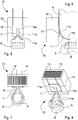
figure 1 is a perspective view of a first embodiment of the laser cutting head of the invention; -
figure 2 is a view of the laser cutting head offigure 1 , without a cooling unit, for better showing focusing means; -
figure 3 is an exploded view of the laser cutting head offigure 1 ; -
figure 4 is a perspective view of the cooling unit associated with the focusing means and supporting means of the laser cutting head offigure 1 ; -
figure 5 is a front view of the cooling unit, focusing means and supporting means offigure 4 ; -
figure 6 is a side view of the cooling unit, focusing means and supporting means offigure 4 ; -
figure 7 is a top plan view of the cooling unit, focusing means and supporting means offigure 4 ; -
figure 8 is a perspective view of a variant of the cooling unit of the laser cutting head of the invention associated with focusing means and supporting means; -
figure 9 is a front view of the cooling unit, focusing means and supporting means offigure 8 ; -
figure 10 is a side view of the cooling unit, focusing means and supporting means offigure 8 ; -
figure 11 is a top plan view of the cooling unit, focusing means and supporting means offigure 8 ; -
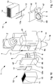
figure 12 is a perspective view of a second embodiment of the laser cutting head of the invention; -
figure 13 is an exploded view of the laser cutting head offigure 12 ; -
figure 14 is another exploded view of the laser cutting head offigure 12 ; -
figure 15 a perspective view of a variant of the laser cutting head offigure 12 ; -
figure 16 is an exploded view of the laser cutting head offigure 15 ; -
figure 17 is a perspective view of the cooling unit associated with the focusing means and supporting means of the laser cutting head offigure 15 ; -
figure 18 is a top plan view of a variant of the cooling unit associated to focusing means and supporting means of the laser cutting head offigure 15 . - With reference to
figures 1 to 7 , alaser cutting head 1 is shown according to a first embodiment of the invention, which is arranged to be powered by a laser emission apparatus, of a known type and not shown in the figures, by means of optical transmission means and associable with a cutting machine tool. In particular, the emission apparatus is of solid-state laser stimulated emission type, and the optical transmission means comprises an optical fiber cable suitable for conveying the laser beam generated by the emission apparatus to thelaser cutting head 1. - The
laser cutting head 1 comprises collimation means 2 for collimating the laser beam generated by the laser emission apparatus, focusingmeans 5 for focusing the collimated laser beam leaving the collimation means 2 and acasing 4 for containing and housing the focusingmeans 5. - The
laser cutting head 1 also comprises a cuttingnozzle 18, that is fixed to thecasing 4 by an optical centering ring-nut 19 and through which the focused laser beam comes out. The cuttingnozzle 18 concentrates a blast or jet of gas for removing the dross generated by the fusion of the workpiece and at the same time limits the probability of this dross reaching the inside of thecasing 4 and the focusingmeans 5. - The collimation means 2 are of known type and comprises a set of lenses and a mirror capable of converging and collimating the laser beam coming from the optical fiber in a rectilinear laser beam directed towards the focusing
means 5. - The focusing means comprises at least one focusing
lens 5. - The
laser cutting head 1 further includes supportingmeans 6 that is arranged to receive and hold the focusinglens 5 and is movable along an adjustment direction X inside thecasing 4 to allow adjusting the focal point or focus of the laser beam coming out from the focusinglens 5. - The supporting means includes a supporting
element 6, which substantially acts as a carriage or slide for the focusinglens 5 and is housed inside acavity 21 of thecasing 4 wherein is slidably moved along the adjustment direction X by drivingmeans 9. - The driving means 9 includes, for example, a linear electric actuator or a recirculating ball screw operated by a rotary electric motor and coupled to the relative lead screw that is connected to the supporting
element 6. The driving means 9 is fixed to thecasing 4 and is connected to the supportingelement 6 through an opening carried out in aside wall 4b of thecasing 4. - The supporting
element 6 comprises a seat 7 suitable for receiving and locking the focusinglens 5. - The
laser cutting head 1 further comprises acooling unit 10, which is externally fixed to thecasing 4 and thermal conductive connectingmeans 11 arranged for connecting the supportingmeans 6 to thecooling unit 10 so as to extract by heat conduction from the supportingelement 6 and the focusinglens 5 the heat that is generated by the laser beam when the latter passes through said focusinglens 5. For this purpose, the supportingelement 6 is made of a thermal conductivity material, preferably a high thermal conductivity material such as aluminium alloy or brass, in order to allow the heat to be transferred from the focusinglens 5. - The thermal conductive connecting
means 11 comprises at least one flexible thermal conductive element made of high thermal conductivity material, for example a braided copper tape and/or graphite-coated tape. - In the embodiment shown in the figures, the flexible thermal
conductive element 11 comprises amain portion 11a, which is fixed to thecooling unit 10 and from which twoelongated portions 11b depart that are secured to opposite sides of supportingelement 6. - In an embodiment that is not shown, the flexible thermal
conductive element 11 may comprise a singleelongated portion 11b in addition to themain portion 11a. - To be noted that the flexibility of the thermal
conductive element 11 in no way hinders the movement of the supportingelement 6 along the adjustment direction X during operation of thelaser cutting head 1 while the thermal conductivity material of the thermalconductive element 11 ensure an optimal heat extraction from the focusinglens 5. - The cooling
unit 10 comprises at least onePeltier cell 12 and aheat dissipation element 13. The flexible thermalconductive device 11 is connected to thecold side 12a of thePeltier cell 12, whereas theheat dissipation element 13 is connected to thehot side 12b of thePeltier cell 12. - The Peltier cell is a thermoelectric device that acts as a solid-state heat pump and typically has the appearance of a thin plate: one of the two sides or faces of the plate absorbs heat while the other emits the heat. The direction in which the heat is transferred depends on the direction of the direct current applied at the ends of this plate. More precisely, a Peltier cell is composed of a plurality of Peltier junctions arranged in series to form a thin plate. The junction is formed of two doped semi-conductors, one N-type and one P-type, connected together by two opposing sheets of copper that form the outside faces or sides of the plate. By applying a direct electric current of opposite voltage to the semi-conductor materials it is possible to cool one side or face of the plate and at the same time to heat the opposite side, thus transferring thermal energy between the two sides of the plate. By inverting the voltage of the electric current supplied to the semi-conductor materials it is possible to invert the thermal energy transfer.
- The
Peltier cell 12 used in thecooling unit 10 is of a known type. - The
laser head 1 comprises acover 16 made of thermal conductivity material, preferably a high thermal conductivity material such as aluminium alloy or brass, to close anopening 17 of thecasing 4 that gives access to thecavity 21 in which the supportingelement 6 and the focusinglens 5 move. - In the embodiment shown in
figure 3 , thecold side 12a of thePeltier cell 12 is fixed to an outer wall of thecover 16 and the flexible thermalconductive element 11 is fixed to the inner wall of thecover 16. - Alternatively, the flexible thermal
conductive element 11 can be directly fixed to thecold side 12a of the Peltier cell through a corresponding opening provided in the cover 16 (figures 4-7 ). - Still alternatively, the
cold side 12a of thePeltier cell 12 can be fixed to anexternal wall 4a, for example a front wall, of thecasing 4 and the flexible thermalconductive element 11 can be directly fixed to thecold side 12a through a corresponding opening which is provided in thecasing 4 and gives access to thecavity 21. - In a version of the cutting head that is not shown, the cooling
unit 10 comprises a plurality ofPeltier cells 12 arranged in series and/or parallel. - The
heat dissipation element 13 comprises a body made of high thermal conductivity material, such as aluminium alloy, provided with a plurality ofcooling ducts 14 that allow the passage of air, in particular by convection, in order to cool the body itself. In the illustrated embodiment, theheat dissipation element 13 has a parallelepiped shape and has a plurality ofcooling ducts 14 arranged side by side and extending along a longitudinal direction, for example parallel to the adjustment direction X. - The
hot side 12b of thePeltier cell 12 is fixed to a rear wall of theheat dissipation element 13. - Thermally conductive adhesives can be used to fix the thermal conductive connecting means 11 to the supporting
means 6 and to thePeltier cell 12. More precisely, thermally conductive adhesives are used to fix the thermal conductive connecting means 11 to the supportingelement 6 and to thecover 16 and/or to thecold side 12a of the Peltier cell and to fix theopposite sides cover 16 and to theheat dissipation element 13. -
Figures 8 to 11 show a version of the coolingunit 10 which comprises intake means 15 arranged for introducing a cooling fluid inside saidcooling ducts 14 in order to increase the heat exchange (forced convection) and to cool thehot side 12b of the Peltier cell more quickly and effectively. The intake means 15 includes, for instance, a couple of nozzles supplied with compressed air and capable of introducing said compressed air into thecooling ducts 14. Adiverter element 20 allows the flow of compressed air coming out from thenozzles 15 to be directed in thecooling ducts 14 so that the cooling fluid, i.e. the compressed air, leaves theheat exchange element 13 directed toward the workpiece. - During the operation of the
laser cutting head 1 of the invention, the heat generated in the focusinglens 5 by the passage of the laser beam coming out from the collimation means 3 (heat generated by the non-absolute transparency of the lens) is transferred and transmitted to the supportingelement 6, to the thermal conductive connectingmeans 11 and to thecold side 12a of thePeltier cell 12. In this way, during the operation of thelaser cutting head 1 the heat is transferred from the focusinglens 5 to thePeltier cell 12, which transfer the heat to the heat dissipation element 13 (fixed to thehot side 12b of said Peltier cell 12). - To be noted that during the operation of the
laser cutting head 1 the focusinglens 5 transfers heat to the supportingelement 6, which transfers heat to the flexible thermalconductive element 11. The heat extraction operated by thePeltier cell 12, which works as a heat pump, allows to control the temperature of the focusinglens 5 and in particular to prevent the overheating of thelens 5 with consequent variation of the lens refractive index and hence a focus shift. - By adjusting the intensity and voltage of the direct electrical current, which powers the
Peltier cell 12, it is possible to control the temperature of the focusinglens 5 during the operation in an accurate and reliable manner. - Thanks to the special cooling system, the
laser cutting head 1 of the invention during operation, even long and intensive, allows to avoid thermal focus shift of the focusinglens 5 and therefore to focus the laser beam in the desired and optimal point with respect to the surface of the workpiece with cutting accuracy and efficiency. - The temperature control and adjustment allows avoiding damage of the protective superficial layer of the focusing
lens 5. - To be noted that thanks to the flexibility of the thermal conductive connecting elements the supporting means and the focusing lens can be effectively cooled by the Peltier cell while they move along the adjustment direction inside the casing for adjusting the focal point of the laser beam.
- The thermal efficiency of the cooling system of the laser cutting head disclosed in the present invention (cooling unit, thermal conductive connecting means and supporting means) is comparable to that of the known gas cooling systems which remove heat from the lens by convection.
- With reference to
figures 12 to 14 , alaser cutting head 1 is shown according to a second embodiment of the invention, which is arranged to be powered by a laser emission apparatus by means of optical transmission means and is associable with a cutting machine tool. - The
laser cutting head 1 comprises collimation means 2 for collimating the laser beam generated by the laser emission apparatus, focusingmeans 5 for focusing the collimated laser beam leaving the collimation means 2 and acasing 4 for containing and housing the focusingmeans 5. - The
laser cutting head 1 also comprises a cuttingnozzle 18, that is fixed to thecasing 4 for example by a ring-nut 19 and through which the focused laser beam comes out. - The collimation means 2 are of known type and may comprise a set of lenses capable of converging and collimating the laser beam coming from the optical transmission means in a rectilinear laser beam. A mirror can be provided for redirecting the laser beam towards the focusing
means 5 that comprises at least one focusinglens 5. - The
laser cutting head 1 comprises supportingmeans 6 arranged for receiving and holding said focusinglens 5 within acavity 21 of saidcasing 4 and movable along an adjustment direction X so as to change a focal point or focus of the said laser beam coming out from said focusingmeans 5. - The
cavity 21 is provided with an accessingopening 17. - The supporting means includes a supporting
element 6 that is provided with a seat 7 suitable for receiving and holding the focusinglens 5. - The
laser cutting head 1 further includes according to the present invention acooling unit 10, which is externally associated to thecasing 4 and is provided with at least onePeltier cell 12 and aheat dissipation element 13, and thermal conductive connectingmeans 31 which is arranged for connecting the supportingmeans 6 to thecooling unit 10 so as to rigidly link said supportingmeans 6 and saidcooling unit 10 and to extract by heat conduction from the supportingelement 6 and the focusinglens 5 the heat that is generated by the laser beam passing through said focusinglens 5. For this purpose, the supportingelement 6 is made of a thermal conductivity material, preferably a high thermal conductivity material such as aluminium alloy or brass. - The
Peltier cell 12 comprises acold side 12a that is connected to the thermal conductive connectingmeans hot side 12b that is connected to theheat dissipation element 13. Theheat dissipation element 13 has a body made of high thermal conductivity material, such as aluminium alloy, and is provided with a plurality ofcooling ducts 14 that allow the passage of air, in particular by natural or forced convection, to cool the body itself. - The cooling
unit 10 may also comprise a plurality ofPeltier cells 12 arranged in parallel and/or in series. - The
laser cutting head 1 includes a movingelement 37 that supports the thermal conductive connectingmeans 31 and/or thecooling unit 10 and is slidably coupled to anexternal wall 4a, for example the front wall, of thecasing 4 and is movable along the adjustment direction X so as to move the supportingmeans 6 and the focusingmeans 5. Driving means 9 is fixed to thecasing 4 and coupled to the movingelement 37 so as to move the latter along said adjustment direction X. - The thermal conductive connecting means comprises a first connecting
element 31 and a second connectingelement 32 both made of a thermal conductivity material, preferably a high thermal conductivity material such as aluminium alloy or brass. The first connectingelement 31 is provided with a first end fixed to, and holding, the supportingelement 6 and a second end fixed to the second connectingelement 32, the latter being connected to thePeltier cell 12, in particular to acold side 12a thereof. - The first connecting
element 31 is shaped substantially as an elongated bracket or arm which is connected to the second connectingelement 32, for example detachably by suitable fastening means. The first connectingelement 31 and second connectingelement 32 can be also made integral. - The second connecting
element 32 has a flat shape with an inner surface to which the first connectingelement 31 is fastened and an external surface which is connected to thecold side 12a of thePeltier cell 12. The flat shape and the dimensions of the second connectingelement 32 allow an efficient and high thermal exchange between the thermal conductive connectingmeans 31, 32 (together with the supportingelement 6 and the focusing lens 5) and thePeltier cell 12. - Thermally conductive adhesives can be used to mutually fix the external surface of the second connecting
element 32 and thecold side 12a of thePeltier cell 12. - The moving
element 37 is coupled to the second connectingelement 32 so as to move the latter together with the first connectingelement 31, the supportingelement 6 and the focusinglens 5 and thecooling unit 10. - Alternatively, the moving
element 37 can directly support the coolingunit 10 and the latter can support the supportingelement 6 and the focusinglens 5 by means of the connectingelements - In the illustrated embodiment, the moving
element 37 comprises a flat element that is slidably coupled to theexternal wall 4a, i.e. a front wall, of thecasing 4 and is provided with arespective opening 37a that gives access to thecavity 21 of thecasing 4. More precisely, theopening 37a of the movingelement 37 allows the connectingelements cooling unit 10 to the supportingelement 6. - The moving
element 37 has a linkingarm 38 that is coupled to the driving means 9. The latter is fixed to aside wall 4b of thecasing 4 and includes for example, a linear electric actuator or a recirculating ball screw operated by a rotary electric motor and connected to the relative lead screw fastened to the linkingarm 38. - During the operation of the
laser cutting head 1 of the invention, the heat generated in the focusinglens 5 by the passage of the laser beam coming out from the collimation means 2 (heat generated by the non-absolute transparency of lens) is transferred and transmitted to the supportingelement 6, to the thermal conductive connectingmeans cold side 12a of thePeltier cell 12. Then thePeltier cell 12 transfers the heat of the focusing lens to theheat dissipation element 13 that is fixed to thehot side 12b. - Hence the
Peltier cell 12 allows controlling the temperature of the focusinglens 5 and in particular to prevent the overheating of the focusinglens 5 with consequent variation of the lens refractive index and hence a focus shift. By adjusting the intensity and voltage of the direct or PWD (pulse-width modulation) electrical current, which powers thePeltier cell 12, it is possible to control the temperature of the focusinglens 5 in an accurate and reliable manner. - Thanks to the special cooling system, the
laser cutting head 1 of the invention during operation, even long and intensive, allows to avoid thermal focus shift of the focusinglens 5 and therefore to focus the laser beam in the desired and optimum point with respect to the surface of the work piece with cutting accuracy and efficiency. - The temperature control and adjustment can help to prevent damage of the protective superficial layer of the focusing
lens 5. - It should be noted that the thermal conductive connecting means and the moving element make possible both to control the temperature of the focusing lens (by means of the Peltier cell) and to move the supporting means and the focusing lens along the adjustment direction in order to adjust the focal point of the laser beam.
- Furthermore the connecting
elements element 37 allowing to easily and quickly remove from thelaser cutting head 1 both thecooling unit 10 and the supportingelement 6 with the focusinglens 5, for maintenance and/or controls. -
Figures 15 to 17 show a variant of thelaser cutting head 1, which differs from the second embodiment offigure 12 to 14 and above described for the different thermal conductive connectingmeans element 47. - In this variant the second connecting
element 42 of the thermal conductive connecting means and the movingelement 47 are mutually fixed so as to form a flat shaped element of which an inner surface is coupled to the first connectingelement 41 of the thermal conductive connecting means and an external surface is connected to thecold side 12a of the Peltier cell. The second connectingelement 42 and the movingelement 47 can be also made integral and in a high thermal conductivity material. - The moving
element 47 has a linkingarm 48 that is coupled to the driving means 9. -
Figure 18 shows another variant of thelaser cutting head 1 of the invention, wherein the coolingunit 10 further comprises intake means 15 arranged for introducing a cooling fluid inside saidcooling ducts 14 of theheat dissipation element 13 in order to increase the heat exchange (forced convection) and to cool thehot side 12b of the Peltier cell more quickly and effectively. The intake means 15 includes, for instance, a couple of nozzles supplied with compressed air and capable of introducing the said expanded air in thecooling ducts 14. Adiverter element 20 allows the flow of compressed air coming out from thenozzles 15 to be directed in thecooling ducts 14 so that the cooling fluid, that is the air, leaves theheat exchange element 13.
Claims (13)
- Laser cutting head powered by a laser emission apparatus by means of optical transmission means and associable with a cutting machine tool, including:- collimation means (2) to collimate a laser beam coming from said laser emission apparatus;- focusing means (5) for focusing a collimated laser beam coming out from said collimation means (2);- a casing (4) for receiving and containing said focusing means (5);- supporting means (6) for receiving and holding said focusing means (5) within a cavity (21) of said casing (4) and movable along an adjustment direction (X) so as to change a focal point of the said laser beam coming out from said focusing means (5);said laser cutting head (1) being characterized in that it comprises:- a cooling unit (10) comprising at least one Peltier cell (12) and a heat dissipation element (13) and externally associated to the casing (4);- thermal conductive connecting means (31, 41; 32, 42) arrange to connect said supporting means (6) to said cooling unit (10) so as to rigidly link said supporting means (6) and said cooling unit (10) and to extract by thermal conduction from said supporting means (6) and from said focusing means (5) heat generated by said laser beam passing through said focusing means (5), wherein said supporting means (6) is made of a thermal conductivity material;- a moving element (37; 47) that supports said thermal conductive connecting means (31, 41; 32, 42) and/or said cooling unit (10) and is slidably coupled to an external wall (4a) of said casing (4) and movable along said adjustment direction (X) so as to move said supporting means (6) and said focusing means (5).
- Laser cutting head according to claim 1, wherein said thermal conductive connecting means (31, 32; 41, 42) comprises a first connecting element (31; 41) and a second connecting element (32; 42), both of which made of a thermal conductivity material, said first connecting element (31; 41) having a first end fixed to, and holding, said supporting means (6) and a second end fixed to said second connecting element (32; 42), which is connected to said Peltier cell (12).
- Laser cutting head according to claim 2, wherein said moving element (37; 47) is coupled to said second connecting element (32; 42).
- Laser cutting head according to claim 2 or 3, wherein said moving element (37) is provided with a respective opening (37a) allowing said connecting elements (31, 32) to connect said supporting means (6) and said Peltier cell (12).
- Laser cutting head according to claim 3, wherein said second connecting element (42) and said moving element (47) are integral and made in a thermal conductivity material.
- Laser cutting head according to any one of claims 2 to 5, wherein said second connecting element (32; 42) and/or said moving element (37; 47) hermetically closes an opening (17) of said cavity (21).
- Laser cutting head according to any preceding claim, wherein said Peltier cell (12) comprises a cold side (12a) connected to said thermal conductive connecting means (31, 32; 41, 42) and a hot side (12b) connected to said heat dissipation element (13).
- Laser cutting head according to any preceding claim, comprising driving means (9) fixed to a said casing (4) and coupled to said moving element (37; 47) so as to move the latter along said adjustment direction (X).
- Laser cutting unit according to any preceding claim, wherein said focusing means comprises at least one focusing lens (5).
- Laser cutting head according to any preceding claim, wherein said cooling unit (10) comprises a plurality of Peltier cells (12) that are arranged in parallel and/or in series.
- Laser cutting head according to any preceding claim, wherein said heat dissipation element (13) comprises a plurality of cooling ducts (14) for the passage of air, in particular by means of convection.
- Laser cutting head according to claim 11, comprising intake means (15) for introducing a cooling fluid, in particular compressed air, into said cooling ducts (14).
- Cutting and/or punching machine tool comprising at least one laser cutting head (1) according to any one of claims 1 to 12.
Priority Applications (2)
| Application Number | Priority Date | Filing Date | Title |
|---|---|---|---|
| PL14809305T PL3071362T3 (en) | 2013-11-22 | 2014-11-20 | Laser cutting head with a cooling unit fixed to the head ; laser cutting and/or punching machine tool with such laser cutting head |
| EP14809305.7A EP3071362B1 (en) | 2013-11-22 | 2014-11-20 | Laser cutting head with a cooling unit fixed to the head ; laser cutting and/or punching machine tool with such laser cutting head |
Applications Claiming Priority (3)
| Application Number | Priority Date | Filing Date | Title |
|---|---|---|---|
| EP13194090.0A EP2875896B1 (en) | 2013-11-22 | 2013-11-22 | Laser cutting head for tool machine with a cooling unit fixed to the head |
| PCT/EP2014/075209 WO2015075152A1 (en) | 2013-11-22 | 2014-11-20 | Laser cutting head for machine tool |
| EP14809305.7A EP3071362B1 (en) | 2013-11-22 | 2014-11-20 | Laser cutting head with a cooling unit fixed to the head ; laser cutting and/or punching machine tool with such laser cutting head |
Publications (2)
| Publication Number | Publication Date |
|---|---|
| EP3071362A1 EP3071362A1 (en) | 2016-09-28 |
| EP3071362B1 true EP3071362B1 (en) | 2018-01-10 |
Family
ID=49766853
Family Applications (2)
| Application Number | Title | Priority Date | Filing Date |
|---|---|---|---|
| EP13194090.0A Active EP2875896B1 (en) | 2013-11-22 | 2013-11-22 | Laser cutting head for tool machine with a cooling unit fixed to the head |
| EP14809305.7A Active EP3071362B1 (en) | 2013-11-22 | 2014-11-20 | Laser cutting head with a cooling unit fixed to the head ; laser cutting and/or punching machine tool with such laser cutting head |
Family Applications Before (1)
| Application Number | Title | Priority Date | Filing Date |
|---|---|---|---|
| EP13194090.0A Active EP2875896B1 (en) | 2013-11-22 | 2013-11-22 | Laser cutting head for tool machine with a cooling unit fixed to the head |
Country Status (11)
| Country | Link |
|---|---|
| US (1) | US10173285B2 (en) |
| EP (2) | EP2875896B1 (en) |
| JP (1) | JP6231684B2 (en) |
| KR (2) | KR20180118819A (en) |
| CN (1) | CN105745050B (en) |
| BR (1) | BR112016011479B1 (en) |
| DK (2) | DK2875896T3 (en) |
| ES (2) | ES2608034T3 (en) |
| PL (2) | PL2875896T3 (en) |
| RU (1) | RU2653892C2 (en) |
| WO (1) | WO2015075152A1 (en) |
Families Citing this family (26)
| Publication number | Priority date | Publication date | Assignee | Title |
|---|---|---|---|---|
| CN104985332B (en) * | 2015-07-10 | 2017-01-25 | 青岛星华智能装备有限公司 | Closed detection method of laser cutting machine |
| US11850681B2 (en) | 2015-10-30 | 2023-12-26 | Hypertherm, Inc. | Highly positioned laser processing nozzle |
| US10549383B2 (en) | 2015-10-30 | 2020-02-04 | Hypertherm, Inc. | Highly positioned laser processing nozzle |
| US10569360B2 (en) | 2015-10-30 | 2020-02-25 | Hypertherm, Inc. | Highly positioned laser processing nozzle |
| US10525554B2 (en) | 2015-10-30 | 2020-01-07 | Hypertherm, Inc. | Water cooling of laser components |
| KR20170087610A (en) * | 2016-01-21 | 2017-07-31 | 삼성전자주식회사 | Apparatus for cutting a wafer |
| JP2019527466A (en) * | 2016-06-14 | 2019-09-26 | エバナ テクノロジーズ ユーエービー | Laser processing system for dicing or cutting multi-segment lenses and wafers |
| FR3054972B1 (en) * | 2016-08-12 | 2019-01-25 | Accelinn | DEVICE FOR TREATING A SURFACE OR ZONE BY LASER BEAM WITH THERMAL HOLDING SYSTEM |
| CN107671433B (en) * | 2017-09-27 | 2019-08-23 | 济南邦德激光股份有限公司 | A kind of laser cutting machine having waste material collection device |
| IT201700121730A1 (en) * | 2017-10-26 | 2019-04-26 | Salvagnini Italia Spa | LASER CUTTING HEAD FOR MACHINE TOOL |
| JP6999401B2 (en) * | 2017-12-19 | 2022-01-18 | 東京エレクトロン株式会社 | Laser processing equipment |
| CN108176927A (en) * | 2018-02-02 | 2018-06-19 | 苏州钋镭自动化科技有限公司 | Laser cutting head |
| CN108838555A (en) * | 2018-06-01 | 2018-11-20 | 苏州福唐智能科技有限公司 | A kind of laser head for laser cutting device |
| CN109773350B (en) * | 2019-01-25 | 2024-03-22 | 苏州迅镭激光科技有限公司 | Air-cooled heat abstractor of laser cutting head |
| CN109865945B (en) * | 2019-01-25 | 2024-03-22 | 苏州迅镭激光科技有限公司 | Laser cutting head with cooling and heat dissipation functions |
| DE102019112167A1 (en) * | 2019-05-09 | 2020-11-12 | Trumpf Laser Gmbh | Processing head for guiding a laser beam and a laser processing device with a processing head |
| US11426817B2 (en) * | 2019-09-26 | 2022-08-30 | Toyota Motor Engineering & Manufacturing North America, Inc. | Lock and fail-safe for laser welding lens |
| IT202000008386A1 (en) * | 2020-04-20 | 2021-10-20 | Prima Ind Spa | LASER OPERATING TERMINAL, LASER OPERATING MACHINE AND CORRESPONDING MANUFACTURING PROCESS |
| CN111922530A (en) * | 2020-08-09 | 2020-11-13 | 刘琳 | Cutting method of high-heat-dissipation laser cutting machine for textile fabric |
| CN112975146A (en) * | 2021-02-05 | 2021-06-18 | 浙江头鲸激光智能制造有限公司 | Convenient to use's laser cutting machine |
| CN113020787B (en) * | 2021-05-18 | 2021-08-17 | 岗春激光科技(江苏)有限公司 | Lens cone and laser cutting head |
| CN113977114A (en) * | 2021-10-13 | 2022-01-28 | 无锡新松机器人自动化有限公司 | Anti-collision mechanism for three-dimensional five-axis laser cutting machine |
| CN113814579A (en) * | 2021-10-13 | 2021-12-21 | 无锡新松机器人自动化有限公司 | Novel three-dimensional five-axis laser cutting head structure |
| CN114289896A (en) * | 2021-12-30 | 2022-04-08 | 杨未来 | Self-circulation type high-efficiency physical circulation cooling laser cutting head |
| CN114722550B (en) * | 2022-05-19 | 2022-08-23 | 北京精雕科技集团有限公司 | Cooling pipeline arrangement method and device, electronic equipment and storage medium |
| KR102636880B1 (en) * | 2023-02-17 | 2024-02-14 | 전호대 | Cutting apparatus for metal rod without using cutting oil |
Family Cites Families (15)
| Publication number | Priority date | Publication date | Assignee | Title |
|---|---|---|---|---|
| CH642891A5 (en) * | 1979-11-21 | 1984-05-15 | Laser Work Ag | METHOD AND DEVICE FOR PROCESSING A WORKPIECE BY LASER BEAM. |
| RU1568390C (en) * | 1988-12-26 | 1995-03-20 | Научно-исследовательский центр по технологическим лазерам | Device for fastening and replacing of optical heads of laser technological complexes |
| DE19827602A1 (en) * | 1998-06-20 | 1999-12-23 | Zeiss Carl Fa | Process for correcting non-rotationally symmetrical image errors |
| JP4667645B2 (en) * | 2001-05-30 | 2011-04-13 | 株式会社アマダ | Laser processing machine having mirror temperature control mechanism and mirror temperature control method for laser processing machine |
| UA47198C2 (en) * | 2001-08-31 | 2004-06-15 | Yurii Vasyliovych Popadynets | Lightguide and the method of using the ligthguide |
| JP3845650B1 (en) * | 2005-06-13 | 2006-11-15 | 株式会社日本製鋼所 | Laser irradiation method and apparatus |
| JP4521478B2 (en) * | 2007-05-17 | 2010-08-11 | 株式会社カネカ | Graphite film and graphite composite film |
| ATE503616T1 (en) * | 2008-11-10 | 2011-04-15 | Jenoptik Automatisierungstech | DEVICE FOR HIGHLY DYNAMIC 3D PROCESSING OF A WORKPIECE USING A LASER BEAM |
| JP2010142859A (en) * | 2008-12-22 | 2010-07-01 | Olympus Corp | Laser beam irradiation apparatus and laser beam machine |
| RU2386523C1 (en) * | 2008-12-25 | 2010-04-20 | Открытое акционерное общество Национальный институт авиационных технологий (ОАО НИАТ) | Device for cutting of volume parts with fibre laser |
| JP5419818B2 (en) * | 2010-07-14 | 2014-02-19 | 三菱電機株式会社 | Laser processing machine |
| JP5651398B2 (en) * | 2010-07-23 | 2015-01-14 | 株式会社アマダ | Processing head of fiber laser processing machine |
| JP5707092B2 (en) * | 2010-10-26 | 2015-04-22 | パナソニック デバイスSunx株式会社 | Laser processing equipment |
| CN201913388U (en) * | 2010-11-23 | 2011-08-03 | 武汉楚天激光(集团)股份有限公司 | Air-cooled cutting head for laser cutter |
| EP2711121B1 (en) * | 2011-05-19 | 2015-12-16 | Murata Machinery, Ltd. | Laser processing machine |
-
2013
- 2013-11-22 EP EP13194090.0A patent/EP2875896B1/en active Active
- 2013-11-22 ES ES13194090.0T patent/ES2608034T3/en active Active
- 2013-11-22 DK DK13194090.0T patent/DK2875896T3/en active
- 2013-11-22 PL PL13194090T patent/PL2875896T3/en unknown
-
2014
- 2014-11-20 KR KR1020187030811A patent/KR20180118819A/en not_active Application Discontinuation
- 2014-11-20 US US15/036,197 patent/US10173285B2/en active Active
- 2014-11-20 DK DK14809305.7T patent/DK3071362T3/en active
- 2014-11-20 KR KR1020167016593A patent/KR101913481B1/en active IP Right Grant
- 2014-11-20 RU RU2016123331A patent/RU2653892C2/en active
- 2014-11-20 PL PL14809305T patent/PL3071362T3/en unknown
- 2014-11-20 BR BR112016011479-5A patent/BR112016011479B1/en active IP Right Grant
- 2014-11-20 CN CN201480063823.7A patent/CN105745050B/en active Active
- 2014-11-20 WO PCT/EP2014/075209 patent/WO2015075152A1/en active Application Filing
- 2014-11-20 EP EP14809305.7A patent/EP3071362B1/en active Active
- 2014-11-20 JP JP2016533202A patent/JP6231684B2/en active Active
- 2014-11-20 ES ES14809305.7T patent/ES2665582T3/en active Active
Also Published As
| Publication number | Publication date |
|---|---|
| PL2875896T3 (en) | 2017-06-30 |
| CN105745050B (en) | 2018-01-09 |
| RU2016123331A (en) | 2017-12-25 |
| JP2016539007A (en) | 2016-12-15 |
| RU2653892C2 (en) | 2018-05-15 |
| BR112016011479B1 (en) | 2022-03-22 |
| KR101913481B1 (en) | 2018-10-30 |
| EP2875896A1 (en) | 2015-05-27 |
| BR112016011479A2 (en) | 2017-08-08 |
| PL3071362T3 (en) | 2018-07-31 |
| ES2665582T3 (en) | 2018-04-26 |
| EP2875896B1 (en) | 2016-10-05 |
| JP6231684B2 (en) | 2017-11-15 |
| KR20160083122A (en) | 2016-07-11 |
| US20160288267A1 (en) | 2016-10-06 |
| WO2015075152A1 (en) | 2015-05-28 |
| EP3071362A1 (en) | 2016-09-28 |
| CN105745050A (en) | 2016-07-06 |
| KR20180118819A (en) | 2018-10-31 |
| ES2608034T3 (en) | 2017-04-05 |
| US10173285B2 (en) | 2019-01-08 |
| DK3071362T3 (en) | 2018-04-23 |
| DK2875896T3 (en) | 2017-01-23 |
Similar Documents
| Publication | Publication Date | Title |
|---|---|---|
| EP3071362B1 (en) | Laser cutting head with a cooling unit fixed to the head ; laser cutting and/or punching machine tool with such laser cutting head | |
| US9731381B2 (en) | Laser cutting head for machine tool | |
| JP6445213B2 (en) | Line beam light source, line beam irradiation apparatus, and laser lift-off method | |
| ES2927973T3 (en) | Laser machining apparatus and laser machining method | |
| WO2015151562A1 (en) | Processing device and processing method | |
| CN102123817A (en) | Chamfering apparatus | |
| US9214368B2 (en) | Laser diode array with fiber optic termination for surface treatment of materials | |
| WO2019082110A1 (en) | Laser cutting head for machine tools | |
| JP2016081994A (en) | Direct diode laser oscillator | |
| KR20140061198A (en) | Laser apparatus | |
| CN106536122B (en) | Laser processing system and laser processing method | |
| CN115255635B (en) | Laser welding system and method | |
| Kubacki et al. | Successful diode laser material processing using application specific micro-optical beam shaping | |
| CN108963730A (en) | A kind of optical fiber ultraviolet laser | |
| JP2023168639A (en) | Laser irradiation method | |
| Ryba et al. | Unique beam delivery and processing tools for high power solid state laser processing |
Legal Events
| Date | Code | Title | Description |
|---|---|---|---|
| PUAI | Public reference made under article 153(3) epc to a published international application that has entered the european phase |
Free format text: ORIGINAL CODE: 0009012 |
|
| 17P | Request for examination filed |
Effective date: 20160621 |
|
| AK | Designated contracting states |
Kind code of ref document: A1 Designated state(s): AL AT BE BG CH CY CZ DE DK EE ES FI FR GB GR HR HU IE IS IT LI LT LU LV MC MK MT NL NO PL PT RO RS SE SI SK SM TR |
|
| AX | Request for extension of the european patent |
Extension state: BA ME |
|
| DAX | Request for extension of the european patent (deleted) | ||
| GRAP | Despatch of communication of intention to grant a patent |
Free format text: ORIGINAL CODE: EPIDOSNIGR1 |
|
| STAA | Information on the status of an ep patent application or granted ep patent |
Free format text: STATUS: GRANT OF PATENT IS INTENDED |
|
| INTG | Intention to grant announced |
Effective date: 20170802 |
|
| GRAS | Grant fee paid |
Free format text: ORIGINAL CODE: EPIDOSNIGR3 |
|
| GRAA | (expected) grant |
Free format text: ORIGINAL CODE: 0009210 |
|
| STAA | Information on the status of an ep patent application or granted ep patent |
Free format text: STATUS: THE PATENT HAS BEEN GRANTED |
|
| AK | Designated contracting states |
Kind code of ref document: B1 Designated state(s): AL AT BE BG CH CY CZ DE DK EE ES FI FR GB GR HR HU IE IS IT LI LT LU LV MC MK MT NL NO PL PT RO RS SE SI SK SM TR |
|
| REG | Reference to a national code |
Ref country code: CH Ref legal event code: EP Ref country code: AT Ref legal event code: REF Ref document number: 961859 Country of ref document: AT Kind code of ref document: T Effective date: 20180115 |
|
| REG | Reference to a national code |
Ref country code: IE Ref legal event code: FG4D |
|
| REG | Reference to a national code |
Ref country code: DE Ref legal event code: R096 Ref document number: 602014019903 Country of ref document: DE |
|
| REG | Reference to a national code |
Ref country code: DK Ref legal event code: T3 Effective date: 20180416 |
|
| REG | Reference to a national code |
Ref country code: ES Ref legal event code: FG2A Ref document number: 2665582 Country of ref document: ES Kind code of ref document: T3 Effective date: 20180426 |
|
| REG | Reference to a national code |
Ref country code: SE Ref legal event code: TRGR |
|
| REG | Reference to a national code |
Ref country code: NL Ref legal event code: MP Effective date: 20180110 |
|
| PG25 | Lapsed in a contracting state [announced via postgrant information from national office to epo] |
Ref country code: NL Free format text: LAPSE BECAUSE OF FAILURE TO SUBMIT A TRANSLATION OF THE DESCRIPTION OR TO PAY THE FEE WITHIN THE PRESCRIBED TIME-LIMIT Effective date: 20180110 |
|
| PG25 | Lapsed in a contracting state [announced via postgrant information from national office to epo] |
Ref country code: NO Free format text: LAPSE BECAUSE OF FAILURE TO SUBMIT A TRANSLATION OF THE DESCRIPTION OR TO PAY THE FEE WITHIN THE PRESCRIBED TIME-LIMIT Effective date: 20180410 Ref country code: HR Free format text: LAPSE BECAUSE OF FAILURE TO SUBMIT A TRANSLATION OF THE DESCRIPTION OR TO PAY THE FEE WITHIN THE PRESCRIBED TIME-LIMIT Effective date: 20180110 Ref country code: LT Free format text: LAPSE BECAUSE OF FAILURE TO SUBMIT A TRANSLATION OF THE DESCRIPTION OR TO PAY THE FEE WITHIN THE PRESCRIBED TIME-LIMIT Effective date: 20180110 Ref country code: CY Free format text: LAPSE BECAUSE OF FAILURE TO SUBMIT A TRANSLATION OF THE DESCRIPTION OR TO PAY THE FEE WITHIN THE PRESCRIBED TIME-LIMIT Effective date: 20180110 |
|
| PG25 | Lapsed in a contracting state [announced via postgrant information from national office to epo] |
Ref country code: IS Free format text: LAPSE BECAUSE OF FAILURE TO SUBMIT A TRANSLATION OF THE DESCRIPTION OR TO PAY THE FEE WITHIN THE PRESCRIBED TIME-LIMIT Effective date: 20180510 Ref country code: BG Free format text: LAPSE BECAUSE OF FAILURE TO SUBMIT A TRANSLATION OF THE DESCRIPTION OR TO PAY THE FEE WITHIN THE PRESCRIBED TIME-LIMIT Effective date: 20180410 Ref country code: GR Free format text: LAPSE BECAUSE OF FAILURE TO SUBMIT A TRANSLATION OF THE DESCRIPTION OR TO PAY THE FEE WITHIN THE PRESCRIBED TIME-LIMIT Effective date: 20180411 Ref country code: LV Free format text: LAPSE BECAUSE OF FAILURE TO SUBMIT A TRANSLATION OF THE DESCRIPTION OR TO PAY THE FEE WITHIN THE PRESCRIBED TIME-LIMIT Effective date: 20180110 Ref country code: RS Free format text: LAPSE BECAUSE OF FAILURE TO SUBMIT A TRANSLATION OF THE DESCRIPTION OR TO PAY THE FEE WITHIN THE PRESCRIBED TIME-LIMIT Effective date: 20180110 |
|
| REG | Reference to a national code |
Ref country code: DE Ref legal event code: R097 Ref document number: 602014019903 Country of ref document: DE |
|
| PG25 | Lapsed in a contracting state [announced via postgrant information from national office to epo] |
Ref country code: EE Free format text: LAPSE BECAUSE OF FAILURE TO SUBMIT A TRANSLATION OF THE DESCRIPTION OR TO PAY THE FEE WITHIN THE PRESCRIBED TIME-LIMIT Effective date: 20180110 Ref country code: AL Free format text: LAPSE BECAUSE OF FAILURE TO SUBMIT A TRANSLATION OF THE DESCRIPTION OR TO PAY THE FEE WITHIN THE PRESCRIBED TIME-LIMIT Effective date: 20180110 Ref country code: RO Free format text: LAPSE BECAUSE OF FAILURE TO SUBMIT A TRANSLATION OF THE DESCRIPTION OR TO PAY THE FEE WITHIN THE PRESCRIBED TIME-LIMIT Effective date: 20180110 |
|
| PLBE | No opposition filed within time limit |
Free format text: ORIGINAL CODE: 0009261 |
|
| STAA | Information on the status of an ep patent application or granted ep patent |
Free format text: STATUS: NO OPPOSITION FILED WITHIN TIME LIMIT |
|
| PG25 | Lapsed in a contracting state [announced via postgrant information from national office to epo] |
Ref country code: CZ Free format text: LAPSE BECAUSE OF FAILURE TO SUBMIT A TRANSLATION OF THE DESCRIPTION OR TO PAY THE FEE WITHIN THE PRESCRIBED TIME-LIMIT Effective date: 20180110 Ref country code: SM Free format text: LAPSE BECAUSE OF FAILURE TO SUBMIT A TRANSLATION OF THE DESCRIPTION OR TO PAY THE FEE WITHIN THE PRESCRIBED TIME-LIMIT Effective date: 20180110 Ref country code: SK Free format text: LAPSE BECAUSE OF FAILURE TO SUBMIT A TRANSLATION OF THE DESCRIPTION OR TO PAY THE FEE WITHIN THE PRESCRIBED TIME-LIMIT Effective date: 20180110 |
|
| 26N | No opposition filed |
Effective date: 20181011 |
|
| PG25 | Lapsed in a contracting state [announced via postgrant information from national office to epo] |
Ref country code: SI Free format text: LAPSE BECAUSE OF FAILURE TO SUBMIT A TRANSLATION OF THE DESCRIPTION OR TO PAY THE FEE WITHIN THE PRESCRIBED TIME-LIMIT Effective date: 20180110 |
|
| PG25 | Lapsed in a contracting state [announced via postgrant information from national office to epo] |
Ref country code: LU Free format text: LAPSE BECAUSE OF NON-PAYMENT OF DUE FEES Effective date: 20181120 Ref country code: MC Free format text: LAPSE BECAUSE OF FAILURE TO SUBMIT A TRANSLATION OF THE DESCRIPTION OR TO PAY THE FEE WITHIN THE PRESCRIBED TIME-LIMIT Effective date: 20180110 |
|
| REG | Reference to a national code |
Ref country code: BE Ref legal event code: MM Effective date: 20181130 |
|
| REG | Reference to a national code |
Ref country code: IE Ref legal event code: MM4A |
|
| PG25 | Lapsed in a contracting state [announced via postgrant information from national office to epo] |
Ref country code: IE Free format text: LAPSE BECAUSE OF NON-PAYMENT OF DUE FEES Effective date: 20181120 |
|
| PG25 | Lapsed in a contracting state [announced via postgrant information from national office to epo] |
Ref country code: BE Free format text: LAPSE BECAUSE OF NON-PAYMENT OF DUE FEES Effective date: 20181130 |
|
| PG25 | Lapsed in a contracting state [announced via postgrant information from national office to epo] |
Ref country code: MT Free format text: LAPSE BECAUSE OF NON-PAYMENT OF DUE FEES Effective date: 20181120 |
|
| REG | Reference to a national code |
Ref country code: AT Ref legal event code: UEP Ref document number: 961859 Country of ref document: AT Kind code of ref document: T Effective date: 20180110 |
|
| PG25 | Lapsed in a contracting state [announced via postgrant information from national office to epo] |
Ref country code: PT Free format text: LAPSE BECAUSE OF FAILURE TO SUBMIT A TRANSLATION OF THE DESCRIPTION OR TO PAY THE FEE WITHIN THE PRESCRIBED TIME-LIMIT Effective date: 20180110 |
|
| PG25 | Lapsed in a contracting state [announced via postgrant information from national office to epo] |
Ref country code: HU Free format text: LAPSE BECAUSE OF FAILURE TO SUBMIT A TRANSLATION OF THE DESCRIPTION OR TO PAY THE FEE WITHIN THE PRESCRIBED TIME-LIMIT; INVALID AB INITIO Effective date: 20141120 Ref country code: MK Free format text: LAPSE BECAUSE OF NON-PAYMENT OF DUE FEES Effective date: 20180110 |
|
| PGFP | Annual fee paid to national office [announced via postgrant information from national office to epo] |
Ref country code: PL Payment date: 20221024 Year of fee payment: 9 |
|
| P01 | Opt-out of the competence of the unified patent court (upc) registered |
Effective date: 20230515 |
|
| PGFP | Annual fee paid to national office [announced via postgrant information from national office to epo] |
Ref country code: GB Payment date: 20231123 Year of fee payment: 10 |
|
| PGFP | Annual fee paid to national office [announced via postgrant information from national office to epo] |
Ref country code: ES Payment date: 20231201 Year of fee payment: 10 |
|
| PGFP | Annual fee paid to national office [announced via postgrant information from national office to epo] |
Ref country code: TR Payment date: 20231116 Year of fee payment: 10 Ref country code: SE Payment date: 20231124 Year of fee payment: 10 Ref country code: IT Payment date: 20231129 Year of fee payment: 10 Ref country code: FR Payment date: 20231127 Year of fee payment: 10 Ref country code: FI Payment date: 20231128 Year of fee payment: 10 Ref country code: DK Payment date: 20231122 Year of fee payment: 10 Ref country code: DE Payment date: 20231121 Year of fee payment: 10 Ref country code: CH Payment date: 20231202 Year of fee payment: 10 Ref country code: AT Payment date: 20231124 Year of fee payment: 10 |
|
| PGFP | Annual fee paid to national office [announced via postgrant information from national office to epo] |
Ref country code: PL Payment date: 20231023 Year of fee payment: 10 |