JP2010142859A - Laser beam irradiation apparatus and laser beam machine - Google Patents
Laser beam irradiation apparatus and laser beam machine Download PDFInfo
- Publication number
- JP2010142859A JP2010142859A JP2008325341A JP2008325341A JP2010142859A JP 2010142859 A JP2010142859 A JP 2010142859A JP 2008325341 A JP2008325341 A JP 2008325341A JP 2008325341 A JP2008325341 A JP 2008325341A JP 2010142859 A JP2010142859 A JP 2010142859A
- Authority
- JP
- Japan
- Prior art keywords
- laser
- unit
- laser beam
- cooling
- irradiation apparatus
- Prior art date
- Legal status (The legal status is an assumption and is not a legal conclusion. Google has not performed a legal analysis and makes no representation as to the accuracy of the status listed.)
- Withdrawn
Links
Images


Abstract
Description
本発明は、レーザ照射装置およびレーザ加工機に関する。例えば、被照射物にレーザを照射して、被照射物を加熱するレーザ照射装置およびそれを備えるレーザ加工機に関する。 The present invention relates to a laser irradiation apparatus and a laser processing machine. For example, the present invention relates to a laser irradiation apparatus that irradiates an irradiation object with a laser and heats the irradiation object, and a laser processing machine including the laser irradiation apparatus.
従来、集光されたレーザ光を用いて局所的な加熱を行って、例えば、はんだ付け、溶接、樹脂の溶着加工などを行うレーザ照射装置およびレーザ加工機が知られている。
このようなレーザ照射装置では、エネルギー変換効率の高さから半導体レーザチップが光源として使われるようになってきた。
半導体レーザは発光時にチップが発熱するが、これによりチップの温度が上昇すると、発光特性が変化したり、素子寿命が低下したりする。そのため、放熱手段や冷却手段を設けて、チップの温度上昇を抑制するようにしている。
例えば、特許文献1には、レーザダイオードチップの温度を一定に保つため、レーザダイオードチップ(半導体レーザ)に、ペルチェ素子およびファン付きヒートシンクが熱的に接続されたレーザダイオードモジュールからなる光源が記載されている。
In such a laser irradiation apparatus, a semiconductor laser chip has come to be used as a light source because of its high energy conversion efficiency.
In semiconductor lasers, the chip generates heat during light emission. When the temperature of the chip rises due to this, the light emission characteristics change or the element lifetime decreases. For this reason, heat dissipation means and cooling means are provided to suppress the temperature rise of the chip.
For example, Patent Document 1 describes a light source including a laser diode module in which a Peltier element and a heat sink with a fan are thermally connected to a laser diode chip (semiconductor laser) in order to keep the temperature of the laser diode chip constant. ing.
しかしながら、上記のような従来のレーザ照射装置およびレーザ加工機には、以下のような問題があった。
特許文献1に記載の発明では、ペルチェ素子およびファン付きヒートシンクが半導体レーザに熱的に接続されているので、光源が大型化して質量も大きくなる。そのため、被加工物(被照射物)にレーザ光を照射するためにレーザ光源を保持する移動機構なども大型化するという問題がある。
また、このようにレーザ光源が大型化すると、加工中に被加工物を観察する撮像カメラの撮像範囲にレーザ光源が映り込み、被加工物の周辺の観察の妨げになるという問題がある。
また、レーザ光源から光ファイバでレーザ光を導光して、集光レンズ内蔵のレンズ鏡筒が設けられた集光ユニットから被加工物にレーザ光を照射する場合、レーザ光源自体の冷却は、撮像カメラの配置位置とレーザ光源配置位置とを遠ざけることができるので、撮像範囲の外側で行うことができるが、集光レンズの開口角の範囲外に放射されるレーザ光がレンズ鏡筒を加熱することになるため、集光ユニットの冷却が必要となる。このため、やはり集光ユニットが大型化するという問題がある。
However, the conventional laser irradiation apparatus and laser processing machine as described above have the following problems.
In the invention described in Patent Document 1, since the Peltier element and the heat sink with the fan are thermally connected to the semiconductor laser, the light source is increased in size and mass. Therefore, there is a problem that a moving mechanism for holding a laser light source for irradiating a workpiece (irradiated object) with laser light is also increased in size.
In addition, when the laser light source is increased in size as described above, there is a problem that the laser light source is reflected in an imaging range of an imaging camera for observing the workpiece during processing, and obstructs observation of the periphery of the workpiece.
In addition, when laser light is guided from an optical fiber from a laser light source and a workpiece is irradiated with laser light from a condensing unit provided with a lens barrel with a built-in condensing lens, the cooling of the laser light source itself is Since the position of the imaging camera and the position of the laser light source can be moved away, it can be performed outside the imaging range, but the laser beam emitted outside the aperture angle range of the condenser lens heats the lens barrel. Therefore, it is necessary to cool the light collecting unit. For this reason, there is still a problem that the light collecting unit is enlarged.
本発明は、上記のような問題に鑑みてなされたものであり、レーザ光を出射するレーザ集光ユニットをコンパクトな構成とすることができるレーザ照射装置およびレーザ加工機を提供することを目的とする。 The present invention has been made in view of the above problems, and an object of the present invention is to provide a laser irradiation apparatus and a laser processing machine that can have a laser condensing unit that emits laser light in a compact configuration. To do.
上記の課題を解決するために、請求項1に記載の発明では、レーザ光を放射するレーザ光源部と、該レーザ光源部から放射されたレーザ光を集光する集光レンズとを有するレーザ集光ユニットと、該レーザ集光ユニットを、被照射物に前記集光レンズで集光された前記レーザ光を照射するための照射位置と、該照射位置から離間した退避位置との間で移動可能に保持するユニット移動部と、前記退避位置に退避された前記レーザ集光ユニットを冷却する冷却部とを備える構成とする。
この発明によれば、ユニット移動部によってレーザ集光ユニットを照射位置に移動させることにより、レーザ光源部から放射されるレーザ光を集光レンズによって集光して、この集光されたレーザ光を被照射物に照射することができる。また、ユニット移動部によってレーザ集光ユニットを退避位置に移動させることにより、冷却部によってレーザ集光ユニットを冷却することができる。
このように、冷却部がレーザ集光ユニットから分離され、ユニット移動部によってレーザ集光ユニットを照射位置と退避位置との間を往復させることで、レーザ集光ユニットの温度上昇を抑制しつつ被照射物に対するレーザ光の照射を続けることができる。
In order to solve the above-described problems, in the invention described in claim 1, a laser light collection unit including a laser light source unit that emits laser light and a condenser lens that collects the laser light emitted from the laser light source unit. The optical unit and the laser condensing unit can be moved between an irradiation position for irradiating the irradiated object with the laser beam condensed by the condensing lens and a retracted position separated from the irradiation position. And a cooling unit that cools the laser focusing unit retracted to the retracted position.
According to this invention, by moving the laser condensing unit to the irradiation position by the unit moving part, the laser light emitted from the laser light source part is condensed by the condenser lens, and the condensed laser light is The irradiated object can be irradiated. Further, the laser focusing unit can be cooled by the cooling unit by moving the laser focusing unit to the retracted position by the unit moving unit.
As described above, the cooling unit is separated from the laser condensing unit, and the unit moving unit reciprocates the laser condensing unit between the irradiation position and the retracted position, thereby suppressing the temperature increase of the laser condensing unit. Irradiation of the laser beam to the irradiated object can be continued.
請求項2に記載の発明では、請求項1に記載のレーザ照射装置において、前記冷却部は、前記レーザ集光ユニットを空冷する冷却ファンを備える構成とする。
この発明によれば、冷却ファンにより退避位置に移動されたレーザ集光ユニットを空冷することができる。
According to a second aspect of the present invention, in the laser irradiation apparatus according to the first aspect, the cooling unit includes a cooling fan that air-cools the laser focusing unit.
According to this invention, the laser focusing unit moved to the retracted position by the cooling fan can be air-cooled.
請求項3に記載の発明では、請求項1または2に記載のレーザ照射装置において、前記冷却部は、前記レーザ集光ユニットに当接可能に設けられた固体冷却素子を備える構成とする。
この発明によれば、固体冷却素子により移動されたレーザ集光ユニットを冷却することができる。
According to a third aspect of the present invention, in the laser irradiation apparatus according to the first or second aspect, the cooling unit includes a solid-state cooling element provided so as to be able to contact the laser focusing unit.
According to this invention, the laser condensing unit moved by the solid state cooling element can be cooled.
請求項4に記載の発明では、レーザ加工機において、被加工物を保持する保持台と、該保持台に保持された前記被加工物を被照射物としてレーザ光を照射する請求項1〜3のいずれかに記載のレーザ照射装置と、前記保持台に保持された前記被加工物を撮像する撮像部とを備える構成とする。
この発明によれば、撮像部によって、保持台に保持された被加工物を撮像しつつ、レーザ照射装置から照射されるレーザ光によって、レーザ加工を行うことができる。そして、請求項1〜3のいずれかに記載のレーザ照射装置を備えるので、請求項1〜3のいずれかに記載の発明と同様の作用を備える。
According to a fourth aspect of the present invention, in the laser processing machine, the holding table for holding the workpiece, and the laser beam is irradiated with the workpiece held on the holding table as the irradiation target. It is set as the structure provided with the laser irradiation apparatus in any one of, and the imaging part which images the said to-be-processed object hold | maintained at the said holding stand.
According to this invention, it is possible to perform laser processing with the laser beam irradiated from the laser irradiation apparatus while imaging the workpiece held on the holding table by the imaging unit. And since the laser irradiation apparatus in any one of Claims 1-3 is provided, it has an effect | action similar to the invention in any one of Claims 1-3.
本発明のレーザ照射装置およびレーザ加工機によれば、冷却部がレーザ集光ユニットから分離され、ユニット移動部によってレーザ集光ユニットを照射位置と退避位置との間を往復させることで、レーザ集光ユニットの温度上昇を抑制しつつ被照射物に対するレーザ照射を続けることができるので、レーザ光を出射するレーザ集光ユニットをコンパクトな構成とすることができるという効果を奏する。 According to the laser irradiation apparatus and the laser processing machine of the present invention, the cooling unit is separated from the laser condensing unit, and the unit moving unit reciprocates the laser condensing unit between the irradiation position and the retracted position, thereby collecting the laser collecting unit. Since it is possible to continue the laser irradiation to the irradiation object while suppressing the temperature rise of the optical unit, there is an effect that the laser condensing unit that emits the laser light can have a compact configuration.
以下では、本発明の実施形態について添付図面を参照して説明する。
本発明の実施形態に係るレーザ照射装置およびレーザ加工機について説明する。
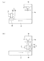
図1(a)は、本発明の実施形態に係るレーザ照射装置を備えるレーザ加工機の概略構成を示す模式的な正面図である。図1(b)は、本発明の実施形態に係るレーザ加工機で撮像された加工中の被加工物周辺の画像の一例を示す模式図である。図2は、本発明の実施形態に係るレーザ照射装置に用いるレーザ集光ユニットの概略構成を示す断面図である。図3は、本発明の実施形態に係るレーザ照射装置の模式的な斜視図である。
Embodiments of the present invention will be described below with reference to the accompanying drawings.
A laser irradiation apparatus and a laser processing machine according to an embodiment of the present invention will be described.
Fig.1 (a) is a typical front view which shows schematic structure of a laser processing machine provided with the laser irradiation apparatus which concerns on embodiment of this invention. FIG. 1B is a schematic diagram illustrating an example of an image around a workpiece being processed, which is captured by the laser processing machine according to the embodiment of the present invention. FIG. 2 is a cross-sectional view showing a schematic configuration of a laser focusing unit used in the laser irradiation apparatus according to the embodiment of the present invention. FIG. 3 is a schematic perspective view of the laser irradiation apparatus according to the embodiment of the present invention.
本実施形態のレーザ加工機50は、被加工物30にレーザ光を照射することにより被加工物30(被照射物)を加熱して、例えば、はんだ付け、溶接、樹脂の溶着加工などの加工作業を行うものである。
以下では、一例として、図1(a)、(b)に示すように、被加工物30がプリント基板30aと電子部品30bとからなり、プリント基板30aのランド部(不図示)に、電子部品30bのリード30cをはんだ付けする場合の例で説明する。
はんだ31は、不図示の支持部材で支持され、先端がはんだ付けを行うリード30cの近傍に位置づけられている。
The
In the following, as an example, as illustrated in FIGS. 1A and 1B, the
The
レーザ加工機50の概略構成は、図1(a)に示すように、被加工物30を保持する保持台10、撮像カメラ13(撮像部)、およびレーザ照射装置1を備える。また、特に図示しないが、レーザ加工機50は撮像カメラ13およびレーザ照射装置1の動作制御を行うため、撮像カメラ13およびレーザ照射装置1に電気的に接続された制御ユニットと、撮像カメラ13によって撮像された画像を表示するモニタとを備えている。
As shown in FIG. 1A, the schematic configuration of the
撮像カメラ13は、保持台10上に保持された被加工物30およびその周辺の領域を撮像して、加工作業を観察するためのものである。撮像カメラ13で撮像された映像は、不図示のモニタに表示される。図1(b)は、撮像カメラ13によって撮像されたはんだ付け作業の中の様子を不図示のモニタの表示画面13Aに表示した画像を示す。
撮像カメラ13は、保持台10の端部に立設された支柱11から水平方向に延ばされた固定アーム12によって、保持台10上の被加工物30に対向する上方位置に支持されている。
The
The
レーザ照射装置1は、レーザ集光ユニット2、ユニット保持部3、ユニット移動部4、冷却ファン保持部5、および冷却ファン6(冷却部)を備える。
The laser irradiation apparatus 1 includes a
レーザ集光ユニット2は、図2に示すように、半導体レーザ21(レーザ光源部)、集光レンズ22、およびこれらを保持するレンズ枠20からなり、半導体レーザ21から発散光として放射されるレーザ光Lを集光レンズ22によって集光し、レンズ枠20の先端部から距離dの点Pに集光するものである。本実施形態では、一例として、d=25(mm)としている。
As shown in FIG. 2, the
集光レンズ22は、レンズ枠20に保持された半導体レーザ21からのレーザ光Lを点Pに集光できるレンズであれば、適宜のレンズ構成を採用することができる。
As long as the
レンズ枠20は、例えばアルミニウム合金などの熱伝導性の良好な金属からなる、全体として略有底円筒状の部材である。
このレンズ枠20は、集光レンズ22を内周部に保持する円筒状の鏡筒部20bと、鏡筒部20bの一端側において半導体レーザ21を集光レンズ22の光軸上に位置決めして固定するレーザ取付部20cと、鏡筒部20bの一端でレーザ取付部20cの範囲を覆うように設けられたレンズ枠端面20dと、レーザ取付部20cを周方向に囲む外周部に設けられた放熱フィン部20aとを備えている。
レーザ取付部20cとレンズ枠端面20dとの間には、放熱フィン部20a側に開口された配線空間20eが形成されている。この配線空間20eには、半導体レーザ21に電流を供給する不図示の電源に接続されたケーブル21Aがレーザ取付部20cの側方の外部から挿入されている。このケーブル21Aの先端部と半導体レーザ21のリードとは、配線空間20eの内部で電気的に接続されている。
The
The
Between the
ユニット保持部3は、レンズ枠20の鏡筒部20bの外周面を外周側から保持する円環状の保持枠3aと、保持枠3aの位置を被加工物30に対して近接または離反するようにユニット移動部4上で移動させるため、ユニット移動部4上に移動可能に保持されたスライダ3bとからなる。
本実施形態のスライダ3bは、その移動方向が保持枠3aに保持されたレーザ集光ユニット2の光軸に沿う方向となるようにユニット移動部4に保持されている。
The
The
ユニット移動部4は、図3に示すように、一方向に延ばされた略角柱状の外形を有し、中心軸を囲む1つの側面に、ユニット保持部3のスライダ3bを1軸方向に移動可能にガイドする1対のガイド溝4aが設けられている。
また、ユニット移動部4の内部には、スライダ3bをガイド溝4aの長手方向の両端部との間で、ガイド溝4aに沿って往復移動させる不図示の移動機構が設けられている。この移動機構としては、例えば、ボールねじ送り機構、リニアモータ、直動アクチュエータなどの適宜の移動機構を採用することができる。
As shown in FIG. 3, the
In addition, a moving mechanism (not shown) that reciprocates the
なお、ユニット移動部4は、ユニット保持部3を互いに離間した2位置の間で往復可能に保持できればよく、2位置の間の移動経路は、直線状に限定されるものではない。
本実施形態の2位置は、ガイド溝4aの長手方向の両端部の2位置とされている。一方の端部の位置4Aは、被加工物30に集光レンズ22で集光されたレーザ光Lを照射するための位置であり、以下では照射位置4Aと称する。また、他方の端部の位置4Bは、照射位置4Aから離間され、撮像カメラ13の撮像範囲外の位置になっている。以下では、位置4Bを退避位置4Bと称する。
The
The two positions in this embodiment are the two positions at both ends in the longitudinal direction of the
ユニット移動部4は、少なくとも加工作業を行う際には、保持部7によって、照射位置4A側の端部が被加工物30に近接するとともに撮像カメラ13の撮像光軸に対して斜めに傾斜する姿勢となるように保持される。
保持部7は、保持台10と位置関係が固定された支持部材であってもよいし、必要に応じて保持位置や保持姿勢を変えることができるように、例えば移動ステージや多軸ロボットなどによって可動に支持されていてもよい。
ユニット移動部4の被加工物30に対する近接位置は、ユニット保持部3が照射位置4Aに移動されたとき、レーザ光Lの集光される点Pが被加工物30を加工可能な位置となるように設定する。
The
The holding unit 7 may be a support member whose positional relationship with the holding table 10 is fixed, and may be changed by, for example, a moving stage or a multi-axis robot so that the holding position and holding posture can be changed as necessary. It may be supported movably.
The proximity position of the
冷却ファン保持部5は、冷却ファン6を退避位置4B上に保持するもので、支持部材5aおよび固定部材5bからなる。
支持部材5aは、ユニット移動部4の退避位置4B側の端部に、ガイド溝4aが設けられたユニット移動部4の側面側に延ばして固定された板状部材である。
固定部材5bは、冷却ファン6を固定するために支持部材5aの先端部の側方に向かって退避位置4Bと対向する範囲に延ばされた固定部材5bからなる。
The cooling
The
The fixing
冷却ファン6は、ユニット移動部4の退避位置4Bに移動されたレーザ集光ユニット2に送風して、レーザ集光ユニット2を空冷するためのもので、ユニット移動部4の退避位置4Bに対向する位置において、冷却ファン保持部5の固定部材5bに保持されている。
The cooling
次に、レーザ加工機50およびレーザ照射装置1の動作について説明する。
図4(a)、(b)は、本発明の実施形態に係るレーザ照射装置のレーザ集光ユニットが、それぞれ照射位置4Aおよび退避位置4Bに配置された様子を示す側面図である。
Next, operations of the
FIGS. 4A and 4B are side views showing a state in which the laser focusing units of the laser irradiation apparatus according to the embodiment of the present invention are arranged at the
レーザ加工機50によって、被加工物30を加工するには、図4(a)に示すように、ユニット移動部4によりユニット保持部3を照射位置4Aに移動させる。
このとき、図1(b)に示すように、撮像カメラ13によって、被加工物30の近傍の様子が撮像され、モニタの表示画面13Aに表示される。本実施形態では、ユニット移動部4の先端部、レーザ集光ユニット2およびユニット保持部3のみが被加工物30に近接される。
In order to process the
At this time, as shown in FIG. 1B, the state of the vicinity of the
そして、半導体レーザ21を励起させて、レーザ光Lを放射させる。レーザ光Lは、図2に示すように、半導体レーザ21の広がり半角θ1の範囲に広がる発散光として放射される。
このようなレーザ光Lのうち、集光レンズ22の開口半角θ0(ただし、θ0<θ1)以下の角度範囲に放射される光は、集光レンズ22によって集光され、点Pに集光される。
Then, the
Of such laser light L, light radiated in an angle range equal to or smaller than the opening half angle θ 0 (where θ 0 <θ 1 ) of the condensing
集光レンズ22によって点Pに集光されたレーザ光Lは、図1(a)に示すように、リード30cの近傍に配置されたはんだ31に照射され、はんだ31を加熱溶融させる。
これにより、リード30cをプリント基板30a上のランド部にはんだ付けすることができる。
As shown in FIG. 1A, the laser light L condensed at the point P by the condensing
Thereby, the lead 30c can be soldered to the land part on the printed
一方、半導体レーザ21から放射されるレーザ光Lのうち、集光レンズ22の開口半角θ0より大きい角度範囲に放射される光は、一部が鏡筒部20bの内部で反射されて迷光として、レーザ集光ユニット2の外部に出射される。また、その他の部分は鏡筒部20bに吸収されて、いずれも光量損失となる。
このうち、鏡筒部20bで吸収される光は、最終的に熱エネルギーに変換されるため、鏡筒部20bを加熱する。
また、半導体レーザ21では、このような励起状態が続くとチップ内で発熱して、この熱が素子パッケージからレーザ取付部20cに放熱される。
このようにして、レンズ枠20に伝導される熱は、鏡筒部20bの表面や放熱フィン部20aから周囲に、ある程度、放熱されていくが、レーザ光Lの放射が続くと、徐々にレンズ枠20に蓄熱されて、半導体レーザ21およびレンズ枠20が温度上昇していく。
On the other hand, among the laser light L emitted from the
Among these, the light absorbed by the
In the
In this way, the heat conducted to the
本実施形態では、半導体レーザ21およびレンズ枠20の温度が許容値を超えないうちに、レーザ光Lの放射を停止する。
そして、図4(b)に示すように、ユニット移動部4によりユニット保持部3を退避位置4Bに移動させる。
レーザ集光ユニット2が退避位置4Bに退避したら、冷却ファン6を回転させてレーザ集光ユニット2に向けて送風し、レーザ集光ユニット2を空冷する。そして、半導体レーザ21およびレンズ枠20の冷却が終了したら、ユニット保持部3の位置を照射位置4Aに切り換えて、はんだ付け作業を続行する。
また、1箇所のはんだ付けが終了したら、レーザ集光ユニット2が退避位置4Bに退避している間に、ユニット移動部4および被加工物30を相対移動させて、点Pの位置が次のはんだ付け箇所になるように設定しておく。
In the present embodiment, the emission of the laser light L is stopped before the temperatures of the
Then, as shown in FIG. 4B, the
When the
When the soldering at one place is completed, the
本実施形態におけるユニット保持部3を照射位置4Aから退避位置4Bに移動させるタイミングは、光量に応じて、半導体レーザチップの温度許容値を超えないような許容点灯時間(パルス点灯する場合には許容パルス数でもよい)を予め実験的に調べておき、このレーザ光Lの点灯時間が許容点灯時間以下となるタイミングに設定している。
The timing for moving the
このようにレーザ加工機50によれば、冷却ファン6がレーザ集光ユニット2から分離され、照射位置4Aから離間された退避位置4Bに対向する位置に配置され、ユニット移動部4によってレーザ集光ユニット2を照射位置4Aと退避位置4Bとの間を往復させることで、レーザ集光ユニット2によるレーザ照射と、冷却とを切り換えて行うことができる。このため、レーザ集光ユニット2から冷却部が分離されているためコンパクトな構成でありながら、レーザ集光ユニット2の温度上昇を抑制しつつ被加工物30に対するレーザ照射を続けることができる。
また、レーザ集光ユニット2に冷却ファン6を一体に設ける場合に比べて、レーザ集光ユニット2が軽量化されるのでレーザ集光ユニット2の移動が容易となり、ユニット移動部4の構成を簡素化、小型化することができる。
また、レーザ集光ユニット2がこのようにコンパクトな構成であるため、照射位置4Aに移動してレーザ光Lを照射する場合に、レーザ集光ユニット2が撮像カメラ13の撮像範囲を遮る範囲が狭くなる。これにより加工作業中でも被加工物30の周辺が観察しやすくなる。
さらに本実施形態では、退避位置4Bは、撮像カメラ13の撮像範囲外に設けられているので、レーザ集光ユニット2の冷却時は、レーザ集光ユニット2が撮像カメラ13の撮像範囲から退避されるため、より広範囲に被加工物30の周辺の様子を観察することができる。
As described above, according to the
Further, as compared with the case where the cooling
Further, since the
Further, in the present embodiment, since the
次に、本実施形態の第1変形例について説明する。
図5は、本発明の実施形態の第1変形例のレーザ照射装置の模式的な斜視図である。図6(a)、(b)は、本発明の実施形態の第1変形例のレーザ照射装置のレーザ集光ユニットが、それぞれ照射位置および退避位置に配置された様子を示す側面図である。
Next, a first modification of the present embodiment will be described.
FIG. 5 is a schematic perspective view of a laser irradiation apparatus according to a first modification of the embodiment of the present invention. FIGS. 6A and 6B are side views showing a state in which the laser focusing units of the laser irradiation apparatus according to the first modification of the embodiment of the present invention are arranged at the irradiation position and the retracted position, respectively.
本変形例のレーザ照射装置1Aは、上記実施形態のレーザ照射装置1の冷却ファン6を削除し、冷却ファン保持部5に代えて、冷却フィン保持部5Aを備え、ペルチェ素子25(冷却部)および放熱フィン26を追加したものである。このようなレーザ照射装置1Aは、上記実施形態のレーザ加工機50において、レーザ照射装置1に代えて用いることができるものである。以下、上記実施形態と異なる点を中心に説明する。
The
冷却フィン保持部5Aは、ペルチェ素子25および放熱フィン26を、ユニット移動部4の退避位置4B側の端部に保持するもので、ユニット移動部4の退避位置4B側の端部に、ガイド溝4aが設けられたユニット移動部4の側面側に延ばして固定され板状部材からなる。
The cooling
ペルチェ素子25は、不図示の制御ユニットから電流の供給を受けて、ペルチェ効果により表裏のうちの一方の素子面を吸熱面25a、他方の素子面を放熱面25bとする固体冷却素子である。
ペルチェ素子25は、吸熱面25aを照射位置4Aが設けられた端部側に向けて、冷却フィン保持部5A上に配置されている。
放熱フィン26は、一部が冷却フィン保持部5Aの貫通孔(不図示)に挿入され、ペルチェ素子25の放熱面25bに熱的に接続された状態で冷却フィン保持部5Aに保持されている。放熱フィン26の材質は、例えばアルミニウム合金などの熱伝導性の良好な金属からなる。
このような構成により、ペルチェ素子25によって放熱面25bに輸送された熱が、放熱フィン26に熱伝導され、放熱フィン26から周囲の空気に熱伝達されることで、ペルチェ素子25によって輸送された熱が空中に放熱されるようになっている。
The
The
A part of the radiating
With such a configuration, the heat transported to the heat radiating surface 25b by the
ペルチェ素子25の配置位置は、図6(b)に示すように、レーザ集光ユニット2およびユニット保持部3が退避位置4Bに移動されたときに、吸熱面25aがレンズ枠20のレンズ枠端面20dと密着して当接し、熱的に接続される位置に設定される。
As shown in FIG. 6B, the arrangement position of the
本変形例のレーザ照射装置1Aによれば、ユニット保持部3を退避位置4Bに移動させると、レンズ枠20のレンズ枠端面20dがペルチェ素子25の吸熱面25aに熱的に接続されるため、レンズ枠20および半導体レーザ21が冷却される。
このため、上記実施形態と同様に、レーザ集光ユニット2から冷却部が分離されているためコンパクトな構成でありながら、レーザ集光ユニット2の温度上昇を抑制しつつ被加工物30に対するレーザ照射を続けることができる。
この結果、ペルチェ素子25の放熱を促進するために大形の放熱フィン26を設けても、レーザ集光ユニット2が照射位置4Aに移動する際は、放熱フィン26が撮像カメラ13の撮像範囲に映り込まないため、被加工物30の周辺の観察が容易となる。
また、レーザ集光ユニット2に送風しなくても、レーザ集光ユニット2を冷却することができるため、送風によって、集光レンズ22にゴミなどが付着することがないので、レーザ集光ユニット2の保守が容易となる。
また、例えば、クリーンルームのように気流を乱すことを嫌う作業環境でも使用することが可能である。
According to the
For this reason, similarly to the above-described embodiment, the cooling unit is separated from the
As a result, even if the large
Further, since the
Also, for example, it can be used in a working environment that dislikes disturbing the airflow, such as in a clean room.
次に、本実施形態の第2変形例について説明する。
図7は、本発明の実施形態の第2変形例のレーザ集光ユニットの概略構成を示す断面図である。
Next, a second modification of the present embodiment will be described.
FIG. 7 is a cross-sectional view showing a schematic configuration of a laser focusing unit of a second modification of the embodiment of the present invention.
本変形例のレーザ集光ユニット2Aは、上記実施形態のレーザ集光ユニット2の半導体レーザ21を削除し、レンズ枠20に代えて、レンズ枠23を備え、光ファイバ24および光ファイバ24にレーザ光を伝送する不図示のレーザ光源を追加したものである。このようなレーザ集光ユニット2Aは、上記実施形態のレーザ加工機50において、支持部材5aに光ファイバ24が挿通可能な貫通孔を設けることで、レーザ集光ユニット2に代えて用いることができるものである。以下、上記実施形態と異なる点を中心に説明する。
The
レンズ枠23は、例えばアルミニウム合金などの熱伝導性の良好な金属からなる、全体として略有底円筒状の部材である。
このレンズ枠23は、集光レンズ22を内周部に保持する円筒状の鏡筒部23bと、鏡筒部23bの一端側を略覆う底部の中心を通り、軸方向に沿って延ばされた段付きの貫通孔である光ファイバ取付部23cと、鏡筒部23bの一端側を略覆う底部の外表面を構成するレンズ枠端面23dとを備えている。
The
The
光ファイバ24は、一方の端部の近傍に光ファイバ取付部23cと嵌合するファイバホルダ24bが設けられ、中間部が支持部材5aに追加された貫通孔(不図示)に挿通され、他方の端部(不図示)は、例えば半導体レーザとカップリングレンズなどからなるレーザ光源に対向されている。
これにより、レーザ光源から出射されたレーザ光Lを光ファイバ24内に伝送して、一方の端部の先端であるファイバ端面24a(レーザ光源部)から広がり半角θ2で発散する発散光として出射されるようになっている。
ファイバ端面24aは、上記実施形態の半導体レーザ21の発光面と同位置に配置され、これにより、ファイバ端面24aから出射されたレーザ光Lのうち、集光レンズ22の開口半角θ0(ただし、θ2>θ0)以下のレーザ光を集光レンズ22によって集光し、レンズ枠23の先端部から距離dの点Pに集光できるようになっている。
The
Thus, emits a laser beam L emitted from the laser light source is transmitted to the
The
このように、レーザ集光ユニット2Aでは、上記実施形態のレーザ光源部とは異なり、半導体レーザ21のような発熱の原因となるレーザ光源を内蔵することなく、外部に設けられたレーザ光源からレーザ光を光ファイバ24で伝送してレンズ枠23内に放射するレーザ光源部を備えている。
このため、レンズ枠23は、集光レンズ22の開口半角θ0より大きい角度範囲に放射されるレーザ光Lによって内部から加熱されるものの、レーザ光源自体の発熱が熱伝導することによる温度上昇はなくなる。
この結果、広がり半角θ2、θ1に大きな差がない場合には、本変形例の冷却部の冷却性能は上記実施形態の冷却部より低くても上記実施形態と同様の冷却効果が得られ、冷却部を小型化することが可能となる。
As described above, in the
For this reason, the
As a result, when there is no large difference between the spread half angles θ 2 and θ 1 , the same cooling effect as that of the above embodiment can be obtained even if the cooling performance of the cooling portion of this modification is lower than that of the cooling portion of the above embodiment. The cooling unit can be reduced in size.
なお、上記の説明では、冷却部として冷却ファン6、またはペルチェ素子25を採用した場合の例で説明したが、冷却部は、レーザ集光ユニットと分離して配置することができるので、冷却部はこれらには限定されない。
例えば、内部に流路を備え流路内に水などの冷媒を循環させる水冷方式の冷却部や、ヒートパイプなどを用いて放熱させる冷却部などであってもよい。
In the above description, the cooling
For example, it may be a water-cooled cooling unit that includes a flow channel inside and circulates a refrigerant such as water in the flow channel, or a cooling unit that radiates heat using a heat pipe or the like.
また、上記の説明では、退避位置4Bに移動させるタイミングは予め設定しておくものとして説明したが、例えば、レンズ枠20、23や半導体レーザ21の温度を直接的または間接的に検出して、一定温度以上になったら退避位置4Bに移動して冷却を行うようにしてもよい。
In the above description, the timing for moving to the retracted
また、上記の第2変形例の説明では、ペルチェ素子25に放熱フィン26が当接された場合の例で説明したが、例えば、放熱フィン26に代えて、冷却フィン保持部5Aを放熱部材として用いてもよい。
In the description of the second modification, the example in which the radiating
また、上記の実施形態、各変形例に説明したすべての構成要素は、本発明の技術的思想の範囲で適宜組み合わせて実施することができる。
例えば、冷却部として、冷却ファン6およびペルチェ素子25を備える構成としてもよい。
In addition, all the constituent elements described in the above embodiment and each modification can be implemented in appropriate combination within the scope of the technical idea of the present invention.
For example, it is good also as a structure provided with the cooling
1、1A レーザ照射装置
2、2A レーザ集光ユニット
3 ユニット保持部
4 ユニット移動部
4A 照射位置
4B 退避位置
5 冷却ファン保持部
5A 冷却フィン保持部
6 冷却ファン(冷却部)
10 保持台
13 撮像カメラ(撮像部)
13A 表示画面
20、23 レンズ枠
20d、23d レンズ枠端面
21 半導体レーザ
22 集光レンズ
24 光ファイバ
24a ファイバ端面(レーザ光源部)
25 ペルチェ素子(冷却部)
26 放熱フィン
30 被加工物(被照射物)
50 レーザ加工機
L レーザ光
DESCRIPTION OF
10 Holding stand 13 Imaging camera (imaging part)
25 Peltier element (cooling part)
26
50 Laser processing machine L Laser light
Claims (4)
該レーザ集光ユニットを、被照射物に前記集光レンズで集光された前記レーザ光を照射するための照射位置と、該照射位置から離間した退避位置との間で移動可能に保持するユニット移動部と、
前記退避位置に退避された前記レーザ集光ユニットを冷却する冷却部とを備えることを特徴とするレーザ照射装置。 A laser condensing unit having a laser light source unit that emits laser light, and a condensing lens that condenses the laser light emitted from the laser light source unit;
A unit that holds the laser condensing unit so as to be movable between an irradiation position for irradiating the irradiated object with the laser light condensed by the condensing lens and a retracted position separated from the irradiation position. A moving part;
A laser irradiation apparatus comprising: a cooling unit that cools the laser focusing unit retracted to the retracted position.
該保持台に保持された前記被加工物を被照射物としてレーザ光を照射する請求項1〜3のいずれかに記載のレーザ照射装置と、
前記保持台に保持された前記被加工物を撮像する撮像部とを備えるレーザ加工機。 A holding table for holding the workpiece;
The laser irradiation apparatus according to any one of claims 1 to 3, wherein the workpiece held on the holding table is irradiated with a laser beam as an irradiation object,
A laser processing machine comprising: an imaging unit that images the workpiece held on the holding table.
Priority Applications (1)
| Application Number | Priority Date | Filing Date | Title |
|---|---|---|---|
| JP2008325341A JP2010142859A (en) | 2008-12-22 | 2008-12-22 | Laser beam irradiation apparatus and laser beam machine |
Applications Claiming Priority (1)
| Application Number | Priority Date | Filing Date | Title |
|---|---|---|---|
| JP2008325341A JP2010142859A (en) | 2008-12-22 | 2008-12-22 | Laser beam irradiation apparatus and laser beam machine |
Publications (1)
| Publication Number | Publication Date |
|---|---|
| JP2010142859A true JP2010142859A (en) | 2010-07-01 |
Family
ID=42563830
Family Applications (1)
| Application Number | Title | Priority Date | Filing Date |
|---|---|---|---|
| JP2008325341A Withdrawn JP2010142859A (en) | 2008-12-22 | 2008-12-22 | Laser beam irradiation apparatus and laser beam machine |
Country Status (1)
| Country | Link |
|---|---|
| JP (1) | JP2010142859A (en) |
Cited By (1)
| Publication number | Priority date | Publication date | Assignee | Title |
|---|---|---|---|---|
| KR101913481B1 (en) * | 2013-11-22 | 2018-10-30 | 살바그니니 이탈리아 에스.피.에이. | Laser cutting head for machine tool |
-
2008
- 2008-12-22 JP JP2008325341A patent/JP2010142859A/en not_active Withdrawn
Cited By (1)
| Publication number | Priority date | Publication date | Assignee | Title |
|---|---|---|---|---|
| KR101913481B1 (en) * | 2013-11-22 | 2018-10-30 | 살바그니니 이탈리아 에스.피.에이. | Laser cutting head for machine tool |
Similar Documents
| Publication | Publication Date | Title |
|---|---|---|
| RU2653892C2 (en) | Laser cutting head for machine tool | |
| US10906073B2 (en) | Adjustable focus laser cleaning galvanometer, cleaning system and cleaning method | |
| CN107303625B (en) | Laser processing machine and laser processing method | |
| JP6885071B2 (en) | Laser machining machine and laser machining method | |
| JPH02142695A (en) | Laser beam machine | |
| JP2008155246A (en) | Laser beam machine | |
| KR101167328B1 (en) | Laser processing device | |
| JP5495574B2 (en) | Laser soldering method | |
| US20200198055A1 (en) | Beam-forming units with cooling systems for high-power lasers | |
| JPH07147297A (en) | Wire bonding device | |
| JP2010142859A (en) | Laser beam irradiation apparatus and laser beam machine | |
| JP6684472B2 (en) | Laser processing equipment | |
| JP2010278248A (en) | Electronic component processing device and electronic component processing method | |
| JP2019177382A (en) | Cooling device and laser processing device | |
| JP2017098064A (en) | Vehicular lighting fixture | |
| JPH0852582A (en) | Laser heating method, device and laser heating tool used therefor | |
| US10886700B2 (en) | Optical module control method, optical module unit, and optical module | |
| JP2007053048A (en) | Processing device using focusing charged particle beam | |
| JP2005353759A (en) | Semiconductor laser device and its manufacturing method | |
| JP6536842B2 (en) | Laser device | |
| KR20000077343A (en) | Laser marking system and method | |
| JP3207939U (en) | Beam shaping optical system and laser solder welding apparatus using the same | |
| JP2011119342A (en) | Laser diode cooling mechanism and laser device equipped with the same | |
| JP4282565B2 (en) | Laser heating device | |
| JP4546881B2 (en) | Stage with temperature control function |
Legal Events
| Date | Code | Title | Description |
|---|---|---|---|
| A300 | Withdrawal of application because of no request for examination |
Free format text: JAPANESE INTERMEDIATE CODE: A300 Effective date: 20120306 |