EP3070729B1 - Finishing assembly and electric switch comprising such a finishing assembly - Google Patents
Finishing assembly and electric switch comprising such a finishing assembly Download PDFInfo
- Publication number
- EP3070729B1 EP3070729B1 EP16305232.7A EP16305232A EP3070729B1 EP 3070729 B1 EP3070729 B1 EP 3070729B1 EP 16305232 A EP16305232 A EP 16305232A EP 3070729 B1 EP3070729 B1 EP 3070729B1
- Authority
- EP
- European Patent Office
- Prior art keywords
- control member
- translucent
- unit according
- trim unit
- trim
- Prior art date
- Legal status (The legal status is an assumption and is not a legal conclusion. Google has not performed a legal analysis and makes no representation as to the accuracy of the status listed.)
- Active
Links
- 230000002093 peripheral effect Effects 0.000 claims description 24
- 239000004417 polycarbonate Substances 0.000 claims description 5
- 229920000515 polycarbonate Polymers 0.000 claims description 5
- 229910000842 Zamak Inorganic materials 0.000 claims description 4
- 239000011435 rock Substances 0.000 claims 3
- 239000002184 metal Substances 0.000 claims 1
- 239000000463 material Substances 0.000 description 10
- 238000005286 illumination Methods 0.000 description 4
- 238000004026 adhesive bonding Methods 0.000 description 3
- 210000000078 claw Anatomy 0.000 description 3
- 230000000295 complement effect Effects 0.000 description 3
- 238000004873 anchoring Methods 0.000 description 2
- 239000011324 bead Substances 0.000 description 2
- 239000004033 plastic Substances 0.000 description 2
- 244000007853 Sarothamnus scoparius Species 0.000 description 1
- 241001080024 Telles Species 0.000 description 1
- 230000015572 biosynthetic process Effects 0.000 description 1
- 239000004020 conductor Substances 0.000 description 1
- 230000001186 cumulative effect Effects 0.000 description 1
- 238000000465 moulding Methods 0.000 description 1
- 210000000056 organ Anatomy 0.000 description 1
- 230000000717 retained effect Effects 0.000 description 1
- 239000007787 solid Substances 0.000 description 1
- 239000012780 transparent material Substances 0.000 description 1
Images
Classifications
-
- H—ELECTRICITY
- H01—ELECTRIC ELEMENTS
- H01H—ELECTRIC SWITCHES; RELAYS; SELECTORS; EMERGENCY PROTECTIVE DEVICES
- H01H23/00—Tumbler or rocker switches, i.e. switches characterised by being operated by rocking an operating member in the form of a rocker button
- H01H23/02—Details
- H01H23/025—Light-emitting indicators
-
- H—ELECTRICITY
- H01—ELECTRIC ELEMENTS
- H01H—ELECTRIC SWITCHES; RELAYS; SELECTORS; EMERGENCY PROTECTIVE DEVICES
- H01H9/00—Details of switching devices, not covered by groups H01H1/00 - H01H7/00
- H01H9/18—Distinguishing marks on switches, e.g. for indicating switch location in the dark; Adaptation of switches to receive distinguishing marks
- H01H9/182—Illumination of the symbols or distinguishing marks
Definitions
- the present invention relates to electrical equipment.
- finishing assembly comprising a control member and a finishing plate, and an electrical switch comprising an apparatus mechanism, a light source and such a finishing assembly.
- the document EP 1 467 387 discloses such an electrical switch in which a peripheral portion of the finishing plate is provided with a central recess delimited by an inner edge of the peripheral portion and wherein the control member is received in the central recess and comprises a portion translucent having a light receiving area, which is illuminated by the light source.
- the present invention provides a finishing assembly as used in the electrical switch mentioned above, characterized in that the finishing plate has a central portion disposed in the central recess and surrounded by the member control, and in that the translucent portion is adapted to transmit, in the direction of the central portion, light received on the receiving area.
- the invention also provides an electrical switch comprising such a finishing assembly, an apparatus mechanism and a light source.
- the light source can thus be arranged to illuminate, directly and / or indirectly, the light receiving zone of the translucent part.
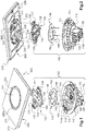
- the Figures 1, 2 and 4 represent an electrical switch comprising an equipment mechanism 100 (here a switching mechanism) and a finishing assembly 200.
- the terms “front” and “rear” will be used relative to the direction of the user's gaze towards the wall wall on which is reported this electrical switch.
- the front will point to the inward side of the room and the back will point to the opposite side toward the outside of the room.
- the equipment mechanism 100 comprises an insulating base 110 forming the support of the equipment mechanism in a housing, such as a flush-mounting box intended to be positioned in a recess of the wall wall where the electrical switch must be installed.
- a housing such as a flush-mounting box intended to be positioned in a recess of the wall wall where the electrical switch must be installed.
- the housing can be mounted protruding on the wall.
- the base 110 comprises a body 112 from which extends forward a side wall 111. This base 110 is open at the front and has a housing adapted to receive the other elements of the fitting mechanism 100.
- the body 112 has a front face 112a which defines this housing with the inner face of the side wall 111.
- the body 112 also has a rear face 112b opposite the front face 112a.
- the equipment mechanism also comprises a cover 120 which is an insulating part mounted in the base (for example by snapping) and which holds conductive electrical parts housed in the base 110, in particular electrical connection terminals to be connected to the local electrical network. .
- these electrical connection terminals are automatically connected terminals, so that each of them is operable by a disconnection lever which passes through an opening in the wall of the base 110 to act on a leaf spring of the corresponding terminal adapted to press the stripped end of an electrical conductor against the cage of the connection terminal.
- Each disconnect lever comprises a control lever 125, carried by the cover 120 and accessible to the user outside said base 110.
- the equipment mechanism 100 also comprises a brush (not shown) adapted to swing about a pivot axis between two extreme positions, to put in contact or out of contact a movable contact element, for example a mobile contact contact worn by the brush, with at least one fixed contact element, for example a fixed contact ground carried by a contact blade electrically connected to one of the electrical connection terminals.
- a brush (not shown) adapted to swing about a pivot axis between two extreme positions, to put in contact or out of contact a movable contact element, for example a mobile contact contact worn by the brush, with at least one fixed contact element, for example a fixed contact ground carried by a contact blade electrically connected to one of the electrical connection terminals.
- the equipment mechanism 100 also comprises a driver 130 pivotally mounted on the base 110 by means of two pins 133 formed on the driver 130 which are respectively engaged in two corresponding bearings 118 formed in the base 110, for example at the top of two protrusions 117 of the body 112 of the base 110, thereby providing a tilting axis of the driver 130 in the base 110.
- the driver 130 is an insulating part, made for example of plastic, typically by molding. In order to be able to diffuse light as explained below, the driver 130 is made of a translucent or even transparent material.
- the driver 130 is here made of polycarbonate.
- the driver 130 comprises a connection portion to a control member 220 (as explained below) and a chimney 136 which extends rearward in a general direction perpendicular to the connecting portion, at the axis tilting, through an opening 124 formed for this purpose in the cover 120.
- the connecting portion of the driver 130 has the general shape of a disc (whose circumference is essentially concentric with the cylindrical side wall 111) from which four arms 131, 132, 134, 135 extend.
- a first arm 134 and a second arm 135 extend respectively on either side of the disk in the general direction of the tilting axis of the driver 130 (and therefore to the right of a pin 133).
- the first arm 134 and the second arm 135 are each provided with a recess 137 (here opening) adapted to cooperate with a complementary portion of the control member 220, as explained below.
- a third arm 131 and a fourth arm 132 extend respectively to either side of the disk in a general direction perpendicular to the axis of tilting of the driver 130.
- the first arm 134, the second arm 135, the third arm 131 and the fourth arm 132 are therefore regularly distributed over the circumference of the disk.
- Each of the third and fourth arms 131, 132 ends at its free end by a bead 139 projecting forward.
- the equipment mechanism 100 comprises an illumination device 140 comprising a printed circuit board 142 on which are mounted one or more light source (s) 146, here a plurality of light-emitting diodes (or LEDs according to the commonly used acronym for Anglo-Saxon).
- the illumination device 140 also comprises a plurality of contact rods 144 which each extend rearwardly from the card 142 and are intended to cooperate with corresponding terminals retained in the cover 120 for the purpose of electrically powering the light sources 146 (this continuously, regardless of the position of the driver 130).
- the card 142 of the illumination device 140 is mounted in the housing formed in the base 110, between the body 112 of the base 110 and the connecting portion of the driver 130.
- the equipment mechanism 100 finally comprises resilient tilting means (not shown), for example a spring mounted in the chimney 136 formed on the driver 130.
- resilient tilting means are capable, after crossing a hard point, to bias the broom towards one or the other of its extreme positions depending on the position of the trainer 130.
- the equipment mechanism 100 is intended to be mounted in a housing (not shown) intended to be mounted on or in a wall, according to a projecting mounting or by embedding this housing on the wall wall.
- pads 114 each having a hole 113 and designed to bear against a bearing surface (not shown) of the base 110: each of these holes 113 is intended to be traversed by the threaded body of a screw (whose head rests on the edge of the hole) intended to be screwed into a corresponding threaded barrel (not shown) of the housing (for example a flush-mounting box), which makes it possible to secure the mechanism of apparatus 100 in the housing by pinching the base 110 between the corresponding wafer 114 and the housing.
- the side wall 111 of the base 110 here of generally cylindrical shape, has, at several places on its inner periphery, a claw 115 intended to cooperate with means for anchoring the finishing assembly 200 already mentioned, as described more bottom, to ensure the assembly of the finishing assembly 200 on the fitting mechanism 100.
- the finishing assembly 200 comprises a finishing plate 210, formed here by a peripheral portion 211 and a central portion 212 separated, a control member 220 and a subplate 230.
- the peripheral portion 211 of the finishing plate 210 has a generally parallelepipedal plate outer shape and has a central recess, here circular whose diameter corresponds (with the clearance) to the outer diameter of the control member 220, here annular, of so that the circular central recess can accommodate the annular control member 220 and, in the center thereof, the central portion 212, here in the form of a disk, as clearly visible on the figure 1 where we can see the finished assembly assembly.
- the peripheral portion 211 of the finishing plate 210 could have other geometries, for example triangular, round (for example circular) or oval.
- the control member 220 extends (in mounted position as visible to figures 1 and 4 ) along a line that forms a closed curve (in the form of a circle in the example described here).
- the central portion 212 of the finishing plate 210 thus extends inside the closed curve formed by the control member. 220, while the peripheral portion 211 extends outside this closed curve.
- the finishing plate 210 comprises an opening (or gap) 215, here an annular space, defined between the inner edge of the central recess of the peripheral portion 211 and the outer edge of the central portion 212, at through which emerges the control member 220 annular.
- the opening of the finishing plate follows a square or rectangular closed line (or a closed line of any other shape, for example triangular or oval), the control member , which is received in this opening, then having a suitable shape which extends in a closed square or rectangular curve (or, generally speaking, of a shape corresponding to that of the opening).
- the sub-plate 230 has a flat front end interrupted in several places so that are defined in this front face, two side portions 231, 232 (a left side portion 231 and a right side portion 232) and two central portions 233, 234 (a left central portion 233 and a central right portion 234).
- the assembly formed by the two central portions 233, 234 is separated from the assembly formed by the two lateral portions 231, 232 by an annular space 243 in which the annular control member 220 is received in the mounted position.
- the assembly formed by the left lateral part 231 and the left central part 233 is furthermore separated from the assembly formed by the right lateral part 232 and by the central right part 234 by a generally rectangular opening 244, which is delimited at each of its two ends by an arm of material 239 connecting the left lateral part 231 and the right lateral part 232 and which is traversed at its center by a cylinder portion 240 connecting the left central part 233 and the right central part 234.
- each central portion 233, 234 is further connected to the corresponding lateral part 231, 232 by means of two bridges 235.
- Each bridge 235 is formed of a first side wall 236 extending rearwardly from the outer periphery of the central portion 233, 234 concerned, a second side wall 237 extending rearwardly from an inner edge of the side portion 231, 232 and a bottom wall 238, substantially parallel to the front face of the sub-plate 220 and recessed relative thereto, and connecting the first side wall 236 and the second side wall 237.
- each bridge 235 thus makes it possible to participate in the mechanical connection of a central portion 233, 234 to a lateral portion 231, 232, while leaving the annular space 243 mentioned above, in particular in the plane of the front face of the sub-plate 230 to receive the annular control member 220 in this annular space 243.
- the outer surface of the second side wall 237 has grooves 242 which form the anchoring means intended to cooperate with a corresponding claw 115 of the base 110 of the apparatus mechanism 100 of in order to retain the finishing assembly 200 on the equipment mechanism 100 as already indicated.
- the second side walls 237 of the bridges 235 all extend in a cylinder of diameter substantially identical to that of the cylindrical side wall 111 of the base 110 of the fitting mechanism 100 so that whereas, during assembly of the finishing assembly 200 on the equipment mechanism 100, the bridges 235 fit into the housing formed as indicated above by the base 110.
- the front face (formed in particular of the side portions 231, 232 and central portions 233, 234) extends over more than half of the available surface area. dimensions of the sub-plate 230. In other words, in the plane of the front face of the sub-plate 230, the surface of the front face (mainly the solid parts 231, 232, 233, 234) is greater than the surface. cumulative annular space 243 and the generally rectangular opening 244.
- the flat front face of the sub-plate 230 thus forms a good support for the finishing plate 210, precisely for the rear face (also flat) of the plate finishing 210, for example for assembly by gluing.
- the sub-plate 230 On two teeth which extend rearward respectively from the rounded outer edges of the left central part 233 and the central right part 234 which delimit the annular space 243, the sub-plate 230 comprises respectively two pins 241 of generally cylindrical shape intended to cooperate with corresponding recesses 221 formed in the annular control member 220 so that the annular control member 220 can be rotatably mounted on the sub-plate 230, along an axis of rotation parallel to the face before the sub-plate 230 and corresponding, in the mounted position of the electrical switch, to the tilting axis of the driver 130 on the base 110.
- Each central portion 233, 234 also has a window designed to leave a free space, in the mounted position, to let the two protruding portions 117 of the bearing body 112 118.
- control member 220 has a generally annular shape which allows it to be located, in the general plane of extension of the finishing plate 210, inside the peripheral portion 211 of the finishing plate 210 and surround the central portion 212 of the finishing package 210.
- control member 220 has a general shape of sphere portion so that the diameter of the control member 220 to its rear peripheral end (located at the rear of the front face of the finishing plate 210 in the mounted position) is greater than the diameter of the control member 220 at its forward peripheral end (located in part at least in front of the front face of the finishing plate 210 in the mounted position), which gives the control member 220 a barrel shape which closely matches the central portion 212 of the finishing plate 210, closing even slightly on this one forward.
- the control member 220 comprises a translucent portion 222, here made of plastic (specifically polycarbonate) and an opaque portion 224, for example metallic, made here zamac.
- the opaque portion 224 comprises at least one recess 228 which leads to to the formation of a complementary catch pin 229 on the translucent portion 222, as visible in FIG. figure 3 .
- the translucent portion 222 extends mainly to the rear of the control member 220, while the opaque portion 224 extends to the front of the control member 220.
- the control member 220 is formed by a ring made of an opaque material (opaque portion 224) which covers a ring made of translucent material (translucent portion 222).
- the opaque portion 224 forms in particular the front end edge 224a (generally annular, here circular) of the control member 220 and the translucent portion 222 forms the rear end edge 222a (generally annular shape, here circular) of the controller 220.
- This rear end edge 222a formed in the translucent portion 222 thus constitutes a light receiving area (or light input area) through which light emitted at the of the equipment mechanism 100 can penetrate into the translucent portion 222.
- the translucent portion 222 extends further forwardly at the inner wall of the controller 220 (i.e. at the wall facing the central portion 212 of the finishing plate 210) at the outer wall of the control member 220 (that is to say at the wall facing the inner edge of the peripheral portion 211 of the finishing plate 220).
- the translucent portion 222 forms an inner wall facing the central portion 212 and the opaque portion 224 forms an outer wall facing the inner edge of the peripheral portion 211, as shown in particular in figure 4 .
- the inner wall of the control member 220 is mainly formed of a translucent material (material of the translucent portion 222), except at its front end 224a, while the outer wall of the control member 220 is mainly formed of an opaque material (material of the opaque portion 224), except at its rear end 222a.
- the opaque part 224 in particular the front end annular edge 224a which will be essentially visible from the outside, once the electric switch is mounted.
- the translucent portion 222 also includes two tabs 223 that extend rearwardly from the rear circular edge of the controller 220 and are also intended to participate in the above-mentioned light receiving area, as explained below. .
- the two recesses 221 intended to receive the cylindrical pins 241 coming from the sub-plate 230 are respectively formed in the two tabs 223.
- the translucent portion 222 finally has two extensions 226, each of which extends slightly rearward from the rear circular edge of the translucent portion 222, on only a portion of the circumference of the rear edge distinct from those carrying the tabs 223. These Extensions 226 may also participate in the aforementioned light receiving area.
- each leg 223 is accommodated in the complementary recess 137 corresponding formed as already indicated in the trainer 130 (as illustrated by the dotted lines on the figure 2 ) so that the tilting of the control member 220 by the user (here around the axis of rotation formed by the cylindrical pins 241, aligned with the tilting axis of the driver 130), which causes in addition to a support of one of the extensions 226 of the organ control 220 on the corresponding bead 139 of the driver 130, causes the tilting of the driver 130 and thus the switching of the electrical switch.
- the light sources 146 illuminate the translucent (or transparent) driver 130, light is diffused in the driver 130 and, via the tabs 223 (made of translucent material as already indicated and thereby forming a part of the light receiving area mentioned above), in the translucent portion 222 of the control member 220.
- Part of the light diffused in the translucent driver 130 is furthermore emitted forwards out of the translucent driver 130 and can thus partly penetrate the translucent portion 222 of the control member 220 through the rear end edge 222a and the extensions 226 (these elements participating in the light receiving area mentioned above).
- Part of the light received on the aforementioned reception zone and diffused in the translucent part 222 is emitted outside the translucent part 222, in particular in the direction of the front face of the finishing plate 210 (precisely of the central part 212 of the finishing plate 210).
- the translucent portion 222 propagates even preferentially the light towards the central portion 212 of the finishing plate 210.
- the translucent portion 222 extends at the level of the internal wall of the control member 220, so as to protrude beyond the front face of the finishing plate 210 (as clearly visible in FIG. figure 4 for one of the two positions).
- the translucent portion 222 illuminates the finishing plate 210 (here in particular its central portion 212) irrespective of the position of the control member 220.
- the front end edge 224a of the control member 220 is formed as already indicated by the opaque portion 224, which thus masks the portion translucent 222, seen from the front when the electrical switch is mounted on a wall.
- the translucent portion 222 illuminates the central portion 212 of the finishing plate 210 but is not itself visible by the user, who sees the control member 220 that the opaque portion 224.
- the designer can to choose quite freely the material of the opaque portion 224, in particular for its external appearance visible by the user.
- the central portion 212 of the finishing plate 210 is fixed (for example by gluing) to the central portions 233, 234 of the front face of the sub-plate 230; the annular control member 220 is then mounted on the sub-plate 230 by cooperation of the cylindrical pins 241 and recesses 221 (playing for example on the elasticity of the tabs 223 during assembly). Finally, the peripheral portion 211 of the finishing plate 210 is fixed (for example by gluing) on the lateral parts 231, 232 of the sub-plate 230.
- the finishing assembly 200 can thus be sold as a unitary product.
- the sub-plate 230 in this case its front face
- the finishing plate 210 here in this case the peripheral portion 211 of the finishing plate 210) have almost the same external dimensions; it can be provided that the finishing plate 210 has dimensions (length, width) slightly greater than those of the front face of the sub-plate 230 so that only the finishing plate 210 can be seen when the electric switch is seen from the front .
- the installer or the user also purchases an equipment mechanism 100 of the type described above and assembles this equipment mechanism 100, as already described above in a casing attached in or on a wall wall.
- the installer or the user then assembles the finishing assembly 200 on the equipment mechanism by simple interlocking of the side wall 111 of the base 110 of the apparatus mechanism 100 and the outer wall of the second side wall 237.
- 235 bridges formed at the rear of the sub-plate 230 (the claws 115 cooperating with the grooves 242 as already explained), which also allows the cooperation (already mentioned) of the tabs 223 of the control member 220 and recesses 137 of the coach 130 and so the command switching of the electric switch by means of the control member 220.
- the finishing plate 210 (composed of its peripheral portion 211 and its central portion 212) completely covers the front face of the sub-plate 230 (in particular the peripheral portions 231, 232 and the central portions 233, 234 of the front face of the sub-plate 230).
- the gap formed between the peripheral portion 211 and the central portion 212 extends to the right of the annular space 243 formed between the central portions 233, 234 and the side portions 231, 232 of the front face of the sub. -plaque 230.
- the slice of the sub-plate 230 is visible to the user once the finishing assembly 200 mounted (through the equipment mechanism 100) on a wall.
Landscapes
- Switch Cases, Indication, And Locking (AREA)
- Breakers (AREA)
- Distribution Board (AREA)
Description
La présente invention concerne l'appareillage électrique.The present invention relates to electrical equipment.
Elle concerne plus particulièrement un ensemble de finition comprenant un organe de commande et une plaque de finition, ainsi qu'un interrupteur électrique comprenant un mécanisme d'appareillage, une source de lumière et un tel ensemble de finition.It relates more particularly to a finishing assembly comprising a control member and a finishing plate, and an electrical switch comprising an apparatus mechanism, a light source and such a finishing assembly.
Le document
De la lumière diffusée dans cette partie translucide est émise vers l'extérieur de l'organe de commande en direction de la partie périphérique de la plaque de finition afin de rendre l'interrupteur électrique visible dans le noir.Light scattered in this translucent portion is emitted outwardly of the controller towards the peripheral portion of the trim plate to render the electrical switch visible in the dark.
Dans ce contexte, la présente invention propose un ensemble de finition tel qu'utilisé dans l'interrupteur électrique mentionné ci-dessus, caractérisé en ce que la plaque de finition comporte une partie centrale disposée dans l'évidement central et entourée par l'organe de commande, et en ce que la partie translucide est conçue pour transmettre, en direction de la partie centrale, de la lumière reçue sur la zone de réception.In this context, the present invention provides a finishing assembly as used in the electrical switch mentioned above, characterized in that the finishing plate has a central portion disposed in the central recess and surrounded by the member control, and in that the translucent portion is adapted to transmit, in the direction of the central portion, light received on the receiving area.
On obtient ainsi un éclairement de cette partie centrale entourée par l'organe de commande, ce qui permet une localisation facile de l'organe de commande dans le noir.This gives an illumination of this central part surrounded by the control member, which allows easy location of the control member in the dark.
D'autres caractéristiques non limitatives et avantageuses de l'interrupteur électrique sont les suivantes :
- l'organe de commande comprend une partie opaque ;
- la partie translucide forme un premier bord d'extrémité annulaire de l'organe de commande situé du côté du mécanisme d'appareillage (ce bord d'extrémité annulaire participant par exemple à la zone de réception de lumière précitée) ;
- la partie opaque forme un second bord d'extrémité annulaire de l'organe de commande situé à l'opposé du premier bord d'extrémité annulaire ;
- sur une partie du flanc de l'organe de commande, la partie translucide forme une paroi interne faisant face à la partie centrale et la partie opaque forme une paroi externe faisant face au bord interne de la partie périphérique ;
- la partie translucide est surmoulée sur la partie opaque ;
- la partie opaque est métallique ;
- la partie opaque est réalisée en zamac ;
- la partie translucide est réalisée en polycarbonate ;
- l'organe de commande est monté à basculement autour d'un axe entre deux positions ;
- la partie translucide comprend des moyens de montage à basculement de l'organe de commande ;
- la partie translucide est conçue pour transmettre de la lumière reçue sur la zone de réception en direction de la partie centrale dans lesdites deux positions de l'organe de commande ;
- la partie centrale et la partie périphérique sont respectivement montées sur une première partie et une seconde partie d'une face avant d'une sous-plaque ;
- la première partie et la seconde partie sont reliées par au moins un pont situé à l'arrière de la sous-plaque ;
- l'organe de commande est monté à basculement sur un axe formé sur la sous-plaque.
- the control member comprises an opaque portion;
- the translucent part forms a first annular end edge of the control member situated on the side of the fitting mechanism (this annular end edge participating for example in the light receiving zone above);
- the opaque portion forms a second annular end edge of the control member located opposite the first annular end edge;
- on a portion of the side of the control member, the translucent portion forms an inner wall facing the central portion and the opaque portion forms an outer wall facing the inner edge of the peripheral portion;
- the translucent part is overmolded on the opaque part;
- the opaque part is metallic;
- the opaque part is made of Zamac;
- the translucent part is made of polycarbonate;
- the control member is mounted to tilt about an axis between two positions;
- the translucent part comprises tilting mounting means of the control member;
- the translucent portion is adapted to transmit light received on the reception area towards the central portion in said two positions of the control member;
- the central portion and the peripheral portion are respectively mounted on a first portion and a second portion of a front face of a sub-plate;
- the first part and the second part are connected by at least one bridge located at the rear of the sub-plate;
- the control member is tiltably mounted on an axis formed on the sub-plate.
L'invention propose également un interrupteur électrique comprenant un tel ensemble de finition, un mécanisme d'appareillage et une source de lumière. La source de lumière peut ainsi être agencée pour éclairer, directement et/ou indirectement, la zone de réception de lumière de la partie translucide.The invention also provides an electrical switch comprising such a finishing assembly, an apparatus mechanism and a light source. The light source can thus be arranged to illuminate, directly and / or indirectly, the light receiving zone of the translucent part.
Selon d'autres caractéristiques optionnelles, et donc non limitatives :
- le mécanisme d'appareillage comprend des moyens pour établir ou interrompre un contact électrique selon la position d'un entraîneur basculant ;
- l'organe de commande comprend des moyens de coopération mécanique avec ledit entraîneur basculant ;
- la source de lumière est montée dans le mécanisme d'appareillage ;
- l'entraîneur est translucide (voire transparent) et interposé entre la source de lumière et l'organe de commande, de telle sorte que la partie translucide est dans ce cas indirectement éclairée par la source de lumière, ici par l'intermédiaire de l'entraîneur (la partie translucide pouvant toutefois en variante être éclairée directement par la source de lumière) ;
- la source de lumière est portée par une plaque montée entre l'entraîneur et un socle du mécanisme d'appareillage ;
- lesdits moyens de coopération mécanique comprennent au moins une patte formée dans la partie translucide et reçue dans un évidement de l'entraîneur (cette patte participant par exemple à la zone de réception de lumière mentionnée plus haut).
- the equipment mechanism comprises means for establishing or interrupting electrical contact according to the position of a tilting driver;
- the control member comprises mechanical cooperation means with said tilting driver;
- the light source is mounted in the fitting mechanism;
- the trainer is translucent (or even transparent) and interposed between the light source and the control member, so that the translucent part is in this case indirectly illuminated by the light source, here via the trainer (the translucent part may alternatively be illuminated directly by the light source);
- the light source is carried by a plate mounted between the driver and a base of the fitting mechanism;
- said mechanical cooperation means comprise at least one tab formed in the translucent part and received in a recess of the coach (this tab participating for example in the light receiving area mentioned above).
La description qui va suivre en regard des dessins annexés, donnés à titre d'exemples non limitatifs, fera bien comprendre en quoi consiste l'invention et comment elle peut être réalisée.The following description with reference to the accompanying drawings, given as non-limiting examples, will make it clear what the invention consists of and how it can be achieved.
Sur les dessins annexés :
- la
figure 1 est une vue en éclaté d'un interrupteur électrique conforme à l'invention ; - la
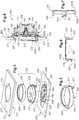
figure 2 est une autre vue en éclaté de l'interrupteur électrique de lafigure 1 ; - la
figure 3 est une vue en éclaté d'un ensemble de finition de l'interrupteur électrique de lafigure 1 ; - la
figure 4 est une vue en coupe de l'interrupteur de lafigure 1 ; - la
figure 5 est une vue en perspective d'un organe de commande de l'interrupteur électrique de lafigure 1 ; - la
figure 6 est une vue en coupe, selon un premier plan de coupe, de l'organe de commande de lafigure 5 ; - la
figure 7 est une vue en coupe, selon un second plan de coupe, de l'organe de commande de lafigure 5 .
- the
figure 1 is an exploded view of an electrical switch according to the invention; - the
figure 2 is another exploded view of the electrical switch of thefigure 1 ; - the
figure 3 is an exploded view of a finishing set of the electrical switch of thefigure 1 ; - the
figure 4 is a sectional view of the switch of thefigure 1 ; - the
figure 5 is a perspective view of a control member of the electrical switch of thefigure 1 ; - the
figure 6 is a sectional view, along a first section plane, of the control member of thefigure 5 ; - the
figure 7 is a sectional view, along a second sectional plane, of the control member of thefigure 5 .
Les
Dans la présente description, les termes « avant » et « arrière » seront utilisés par rapport à la direction du regard de l'usager vers la paroi murale sur laquelle est rapporté cet interrupteur électrique. Ainsi, lorsque l'interrupteur électrique sera installé dans une pièce, l'avant désignera le côté tourné vers l'intérieur de la pièce et l'arrière désignera le côté tourné à l'opposé, vers l'extérieur de la pièce.In the present description, the terms "front" and "rear" will be used relative to the direction of the user's gaze towards the wall wall on which is reported this electrical switch. Thus, when the power switch is installed in a room, the front will point to the inward side of the room and the back will point to the opposite side toward the outside of the room.
Le mécanisme d'appareillage 100 comprend un socle 110 isolant formant support du mécanisme d'appareillage dans un boîtier, tel qu'une boîte d'encastrement destinée à être positionnée dans un évidement de la paroi murale où doit être installé l'interrupteur électrique. En variante, le boîtier peut être monté en saillie sur la paroi murale.The
Le socle 110 comporte un corps 112 à partir duquel s'étend vers l'avant une paroi latérale 111. Ce socle 110 est ouvert à l'avant et présente un logement adapté à recevoir les autres éléments du mécanisme d'appareillage 100.The
Le corps 112 présente une face avant 112a qui délimite ce logement avec la face intérieure de la paroi latérale 111. Le corps 112 présente également une face arrière 112b à l'opposé de la face avant 112a.The
Le mécanisme d'appareillage comporte également un capot 120 qui est une pièce isolante montée dans le socle (par exemple par encliquetage) et qui retient des pièces électriques conductrices logées dans le socle 110, notamment des bornes de connexion électrique à raccorder au réseau électrique local. De manière classique, ces bornes de connexion électrique sont des bornes à connexion automatique, de sorte que chacune d'entre elles est manoeuvrable par un levier de déconnexion qui traverse une ouverture pratiquée dans la paroi du socle 110 pour agir sur une lame-ressort de la borne correspondante adaptée à plaquer l'extrémité dénudée d'un conducteur électrique contre la cage de la borne de connexion. Chaque levier de déconnexion comporte une manette de commande 125, portée par le capot 120 et accessible à l'usager à l'extérieur dudit socle 110.The equipment mechanism also comprises a
Le mécanisme d'appareillage 100 comporte également un balai (non représenté) adapté à basculer autour d'un axe de basculement entre deux positions extrêmes, pour mettre en contact ou hors contact un élément de contact mobile, par exemple un grain de contact mobile porté par le balai, avec au moins un élément de contact fixe, par exemple un grain de contact fixe porté par une lame de contact raccordée électriquement à l'une des bornes de connexion électrique.The
Le mécanisme d'appareillage 100 comporte également un entraîneur 130 monté basculant sur le socle 110 au moyen de deux pions 133 formés sur l'entraîneur 130 qui sont respectivement engagés dans deux paliers correspondants 118 formés dans le socle 110, par exemple au sommet de deux parties saillantes 117 du corps 112 du socle 110, réalisant ainsi un axe de basculement de l'entraîneur 130 dans le socle 110.The
L'entraîneur 130 est une pièce isolante, réalisée par exemple en matière plastique, typiquement par moulage. Afin de pouvoir diffuser la lumière comme expliqué plus bas, l'entraîneur 130 est réalisé dans un matériau translucide, voire transparent. L'entraîneur 130 est ici réalisé en polycarbonate.The
L'entraîneur 130 comprend une partie de liaison à un organe de commande 220 (comme expliqué plus bas) et une cheminée 136 qui s'étend vers l'arrière selon une direction générale perpendiculaire à la partie de liaison, au niveau de l'axe de basculement, à travers une ouverture 124 ménagée à cet effet dans le capot 120.The
La partie de liaison de l'entraîneur 130 présente la forme générale d'un disque (dont la circonférence est pour l'essentiel concentrique avec la paroi latérale cylindrique 111) à partir duquel s'étendent quatre bras 131, 132, 134, 135.The connecting portion of the
Un premier bras 134 et un second bras 135 s'étendent respectivement de part et d'autre du disque dans la direction générale de l'axe de basculement de l'entraîneur 130 (et donc au droit d'un pion 133). Le premier bras 134 et le second bras 135 sont chacun pourvus d'un évidement 137 (ici débouchant) propre à coopérer avec une partie complémentaire de l'organe de commande 220, comme expliqué plus loin.A
Un troisième bras 131 et un quatrième bras 132 s'étendent quant à eux respectivement de part et d'autre du disque dans une direction générale perpendiculaire à l'axe de basculement de l'entraîneur 130. Dans l'exemple décrit, le premier bras 134, le second bras 135, le troisième bras 131 et le quatrième bras 132 sont donc régulièrement répartis sur la circonférence du disque.A
Chacun des troisième et quatrième bras 131, 132 se termine à son extrémité libre par un bourrelet 139 en saillie vers l'avant.Each of the third and
Le mécanisme d'appareillage 100 comporte un dispositif d'illumination 140 comprenant une carte à circuit imprimé 142 sur laquelle sont montées une ou plusieurs source(s) de lumière 146, ici une pluralité de diodes électroluminescents (ou LEDs selon l'acronyme anglo-saxon couramment utilisé). Le dispositif d'illumination 140 comprend également une pluralité de tiges de contact 144 qui s'étendent chacune vers l'arrière à partir de la carte 142 et sont destinées à coopérer avec des bornes correspondantes retenues dans le capot 120 en vue d'alimenter électriquement les sources de lumière 146 (ce de manière continue, indépendamment de la position de l'entraîneur 130).The
Comme bien visible sur les
Le mécanisme d'appareillage 100 comporte enfin des moyens élastiques de basculement (non représentés), par exemple un ressort monté dans la cheminée 136 formée sur l'entraîneur 130. Ces moyens élastiques de basculement sont aptes, après franchissement d'un point dur, à solliciter le balai en direction de l'une ou de l'autre de ses positions extrêmes en fonction de la position de l'entraîneur 130.The
Comme déjà indiqué, le mécanisme d'appareillage 100 est destiné à être monté dans un boîtier (non représenté) destiné à être rapporté sur ou dans une paroi murale, selon un montage en saillie ou par encastrement de ce boîtier sur la paroi murale. On prévoit ici pour ce faire des plaquettes 114 présentant chacun un trou 113 et conçues pour venir en appui sur une surface d'appui (non représentée) du socle 110 : chacun de ces trous 113 est destiné à être traversé par le corps fileté d'une vis (dont la tête repose sur le bord du trou) destinée à être vissée dans un fût taraudé correspondant (non représenté) du boîtier (par exemple une boîte d'encastrement), ce qui permet d'assurer la fixation du mécanisme d'appareillage 100 dans le boîtier par pincement du socle 110 entre la plaquette 114 correspondante et le boîtier.As already indicated, the
Comme le montre la
Comme bien visible en
La partie périphérique 211 de la plaque de finition 210 a une forme générale extérieure de plaque parallélépipédique et présente un évidement central, ici circulaire dont le diamètre correspond (au jeu près) au diamètre extérieur de l'organe de commande 220, ici annulaire, de sorte que l'évidement central circulaire peut loger l'organe de commande annulaire 220 et, au centre de celui-ci, la partie centrale 212, ici se présentant sous la forme d'un disque, comme bien visible sur la
Dans le plan général d'extension de la plaque de finition 210 (qui est parallèle au plan général d'extension de la sous-plaque 230 comme décrit ci-après), l'organe de commande 220 s'étend (en position montée comme visible aux
En d'autres termes la plaque de finition 210 comprend une ouverture (ou interstice) 215, ici un espace annulaire, définie entre le bord interne de l'évidement central de la partie périphérique 211 et le bord externe de la partie centrale 212, au travers de laquelle émerge l'organe de commande 220 annulaire.In other words, the finishing
Bien entendu, selon d'autres variantes, on pourrait prévoir que l'ouverture de la plaque de finition suive une ligne fermée carrée ou rectangulaire (ou une ligne fermée de toute autre forme, par exemple triangulaire ou ovale), l'organe de commande, qui est reçu dans cette ouverture, présentant alors une forme adaptée qui s'étend suivant une courbe fermée carrée ou rectangulaire (ou, de manière générale, de forme correspondant à celle de l'ouverture).Of course, according to other variants, it could be provided that the opening of the finishing plate follows a square or rectangular closed line (or a closed line of any other shape, for example triangular or oval), the control member , which is received in this opening, then having a suitable shape which extends in a closed square or rectangular curve (or, generally speaking, of a shape corresponding to that of the opening).
Comme le montre plus particulièrement la
L'ensemble formé par les deux parties centrales 233, 234 est séparé de l'ensemble formé par les deux parties latérales 231, 232 par un espace annulaire 243 dans lequel l'organe de commande annulaire 220 est reçu en position montée.The assembly formed by the two
L'ensemble formé par la partie latérale gauche 231 et par la partie centrale gauche 233 est par ailleurs séparé de l'ensemble formé par la partie latérale droite 232 et par la partie centrale droite 234 par une ouverture globalement rectangulaire 244, qui est délimitée à chacune de ses deux extrémités par un bras de matière 239 reliant la partie latérale gauche 231 et la partie latérale droite 232 et qui est traversée en son centre par une portion de cylindre 240 reliant la partie centrale gauche 233 et la partie centrale droite 234.The assembly formed by the left
Comme bien visible sur la
Grâce à sa forme, chaque pont 235 permet ainsi de participer à la liaison mécanique d'une partie centrale 233, 234 à une partie latérale 231, 232, tout en laissant libre l'espace annulaire 243 mentionné ci-dessus notamment dans le plan de la face avant de la sous-plaque 230 afin de recevoir l'organe de commande annulaire 220 dans cet espace annulaire 243.Because of its shape, each
On remarque par ailleurs que, pour chaque pont 235, la surface externe de la seconde paroi latérale 237 présente des rainures 242 qui forment les moyens d'ancrage destinés à venir coopérer avec une griffe 115 correspondante du socle 110 du mécanisme d'appareillage 100 de manière à retenir l'ensemble de finition 200 sur le mécanisme d'appareillage 100 comme déjà indiqué.Note also that, for each
À cet égard, les secondes parois latérales 237 des ponts 235 s'étendent toutes dans un cylindre de diamètre sensiblement identique à celui de la paroi latérale cylindrique 111 du socle 110 du mécanisme d'appareillage 100 de sorte que, lors du montage de l'ensemble de finition 200 sur le mécanisme d'appareillage 100, les ponts 235 s'emboîtent dans le logement formé comme indiqué plus haut par le socle 110.In this respect, the
Malgré les interruptions de matière (espace annulaire 243, ouverture globalement rectangulaire 244), la face avant (formée notamment des parties latérales 231, 232 et des parties centrales 233, 234) s'étend sur plus de la moitié de la surface disponible du fait des dimensions de la sous-plaque 230. Autrement dit, dans le plan de la face avant de la sous-plaque 230, la surface de la face avant (principalement les parties pleines 231, 232, 233, 234) est supérieure à la surface cumulée de l'espace annulaire 243 et de l'ouverture globalement rectangulaire 244. La face avant plane de la sous-plaque 230 forme donc un bon support pour la plaque de finition 210, précisément pour la face arrière (également plane) de la plaque de finition 210, par exemple en vue d'un assemblage par collage.Despite interruptions of material (
Sur deux dents qui s'étendent vers l'arrière respectivement à partir des bords externes arrondis de la partie centrale gauche 233 et de la partie centrale droite 234 qui délimitent l'espace annulaire 243, la sous-plaque 230 comporte respectivement deux pions 241 de forme générale cylindrique destinés à coopérer avec des évidements correspondants 221 formés dans l'organe de commande annulaire 220 de sorte que l'organe de commande annulaire 220 puisse être monté rotatif sur la sous-plaque 230, selon un axe de rotation parallèle à la face avant de la sous-plaque 230 et qui correspond, en position montée de l'interrupteur électrique, à l'axe de basculement de l'entraîneur 130 sur le socle 110.On two teeth which extend rearward respectively from the rounded outer edges of the left
Chaque partie centrale 233, 234 présente par ailleurs une fenêtre conçue pour laisser un espace libre, en position montée, pour laisser passer les deux parties saillantes 117 du corps 112 formant palier 118.Each
Comme nous l'avons déjà décrit précédemment, l'organe de commande 220 a une forme générale annulaire qui lui permet d'être situé, dans le plan d'extension générale de la plaque de finition 210, à l'intérieur de la partie périphérique 211 de la plaque de finition 210 et d'entourer la partie centrale 212 de la paque de finition 210.As already described above, the
Précisément, l'organe de commande 220 a une forme générale de portion de sphère de sorte que le diamètre de l'organe de commande 220 à son extrémité périphérique arrière (située à l'arrière de la face avant de la plaque de finition 210 en position montée) est supérieur au diamètre de l'organe de commande 220 à son extrémité périphérique avant (située en partie au moins à l'avant de la face avant de la plaque de finition 210 en position montée), ce qui confère à l'organe de commande 220 une forme de tonneau qui épouse au plus près la partie centrale 212 de la plaque de finition 210, en se refermant même légèrement sur celle-ci vers l'avant.Precisely, the
Comme visible en particulier sur les
La partie translucide 222 s'étend principalement à l'arrière de l'organe de commande 220, tandis que la partie opaque 224 s'étend à l'avant de l'organe de commande 220. Autrement dit, l'organe de commande 220 est formé par un anneau réalisé dans un matériau opaque (partie opaque 224) qui recouvre un anneau réalisé dans matériau translucide (partie translucide 222).The
Précisément, la partie opaque 224 forme notamment le bord d'extrémité avant 224a (de forme générale annulaire, ici circulaire) de l'organe de commande 220 et la partie translucide 222 forme le bord d'extrémité arrière 222a (de forme générale annulaire, ici circulaire) de l'organe de commande 220. Ce bord d'extrémité arrière 222a formé dans la partie translucide 222 constitue ainsi une zone de réception de lumière (ou zone d'entrée de lumière) à travers laquelle de la lumière émise au niveau du mécanisme d'appareillage 100 peut pénétrer dans la partie translucide 222.Specifically, the
On remarque par ailleurs que la partie translucide 222 s'étend davantage vers l'avant au niveau de la paroi interne de l'organe de commande 220 (c'est-à-dire au niveau de la paroi faisant face à la partie centrale 212 de la plaque de finition 210) qu'au niveau de la paroi externe de l'organe de commande 220 (c'est-à-dire au niveau de la paroi faisant face au bord interne de la partie périphérique 211 de la plaque de finition 220).Note also that the
Autrement dit, sur une partie des flancs de l'organe de commande 220 (et notamment dans au moins un plan de section parallèle à une face avant de la plaque de finition 210), la partie translucide 222 forme une paroi interne faisant face à la partie centrale 212 et la partie opaque 224 forme une paroi externe faisant face au bord interne de la partie périphérique 211, comme montré notamment en
Ainsi, comme bien visible en
La partie translucide 222 comporte également deux pattes 223 qui s'étendent vers l'arrière à partir du bord circulaire arrière de l'organe de commande 220 et sont également destinées à participer à la zone de réception de lumière susmentionnée, comme expliqué ci-après. Dans l'exemple décrit ici, les deux évidements 221 destinés à recevoir les pions cylindriques 241 issus de la sous-plaque 230 sont respectivement formés dans les deux pattes 223.The
La partie translucide 222 comporte enfin deux prolongements 226 qui s'étendent chacun légèrement vers l'arrière à partir du bord circulaire arrière de la partie translucide 222, sur une partie seulement de la circonférence du bord arrière distincte de celles portant les pattes 223. Ces prolongements 226 peuvent également participer à la zone de réception de lumière précitée.The
En position montée de l'interrupteur électrique (c'est-à-dire lorsque l'ensemble de finition 200 est monté sur le mécanisme d'appareillage 100), l'extrémité arrière de chaque patte 223 est logée dans l'évidement complémentaire 137 correspondant formé comme déjà indiqué dans l'entraîneur 130 (comme illustré par les pointillés sur la
Par ailleurs, du fait que les sources de lumière 146 éclairent l'entraîneur translucide (voire transparent) 130, de la lumière est diffusée dans l'entraîneur 130 et, par l'intermédiaire des pattes 223 (réalisées en matériau translucide comme déjà indiqué et formant ainsi une partie de la zone de réception de lumière mentionnée plus haut), dans la partie translucide 222 de l'organe de commande 220.Moreover, because the
Une partie de la lumière diffusée dans l'entraîneur translucide 130 est par ailleurs émise vers l'avant en dehors de l'entraîneur translucide 130 et peut ainsi, pour partie, pénétrer dans la partie translucide 222 de l'organe de commande 220 à travers le bord d'extrémité arrière 222a et les prolongements 226 (ces éléments participant à la zone de réception de lumière mentionnée plus haut).Part of the light diffused in the
Une partie de la lumière reçue sur la zone de réception précitée et diffusée dans la partie translucide 222 est émise en dehors de la partie translucide 222, notamment en direction de la face avant de la plaque de finition 210 (précisément de la partie centrale 212 de la plaque de finition 210).Part of the light received on the aforementioned reception zone and diffused in the
Du fait de la forme particulière de la partie translucide 222 déjà mentionnée (la partie translucide 222 s'étendant plus vers l'avant au niveau de la paroi interne de l'organe de commande 220 qu'au niveau de sa paroi externe), la partie translucide 222 propage même préférentiellement la lumière en direction de la partie centrale 212 de la plaque de finition 210.Due to the particular shape of the
On remarque d'ailleurs que, quelle que soit la position de l'organe de commande 220 (parmi les deux positions stables correspondant aux deux positions de commutation de l'entraîneur 130), la partie translucide 222 s'étend, au niveau de la paroi interne de l'organe de commande 220, de manière à dépasser au-delà de la face avant de la plaque de finition 210 (comme bien visible en
Le bord d'extrémité avant 224a de l'organe de commande 220 est formé comme déjà indiqué par la partie opaque 224, qui masque ainsi la partie translucide 222, vu de l'avant lorsque l'interrupteur électrique est monté sur une paroi. Ainsi, la partie translucide 222 éclaire la partie centrale 212 de la plaque de finition 210 mais n'est pas elle-même visible par l'utilisateur, qui ne voit de l'organe de commande 220 que la partie opaque 224. Le concepteur peut choisir assez librement le matériau de la partie opaque 224, notamment pour son aspect extérieur visible par l'utilisateur.The
Pour l'assemblage de l'ensemble de finition 200, la partie centrale 212 de la plaque de finition 210 est fixée (par exemple par collage) sur les parties centrales 233, 234 de la face avant de la sous-plaque 230 ; l'organe de commande annulaire 220 est ensuite monté sur la sous-plaque 230 par coopération des pions cylindriques 241 et des évidements 221 (en jouant par exemple sur l'élasticité des pattes 223 lors du montage). Enfin, la partie périphérique 211 de la plaque de finition 210 est fixée (par exemple par collage) sur les parties latérales 231, 232 de la sous-plaque 230.For the assembly of the finishing
L'ensemble de finition 200 peut ainsi être vendu sous forme d'un produit monobloc.The finishing
On remarque que, dans l'exemple décrit ici, la sous-plaque 230 (en l'occurrence sa face avant) et la plaque de finition 210 (ici en l'occurrence la partie périphérique 211 de la plaque de finition 210) ont quasiment les mêmes dimensions extérieures ; on peut prévoir que la plaque de finition 210 ait des dimensions (longueur, largeur) légèrement supérieures à celles de la face avant de la sous-plaque 230 afin que seule soit visible la plaque de finition 210 lorsque l'interrupteur électrique est vu de face.Note that, in the example described here, the sub-plate 230 (in this case its front face) and the finishing plate 210 (here in this case the
L'installateur ou l'utilisateur achète par ailleurs un mécanisme d'appareillage 100 du type de celui décrit ci-dessus et monte ce mécanisme d'appareillage 100, comme déjà décrit ci-dessus dans un boîtier rapporté dans ou sur une paroi murale.The installer or the user also purchases an
L'installateur ou l'utilisateur monte alors l'ensemble de finition 200 sur le mécanisme d'appareillage par simple emboîtement de la paroi latérale 111 du socle 110 du mécanisme d'appareillage 100 et de la paroi externe de la seconde paroi latérale 237 des ponts 235 formés à l'arrière de la sous-plaque 230 (les griffes 115 coopérant avec les rainures 242 comme déjà expliqué), ce qui permet également la coopération (déjà mentionnée) des pattes 223 de l'organe de commande 220 et des évidements 137 de l'entraîneur 130 et donc la commande de la commutation de l'interrupteur électrique au moyen de l'organe de commande 220.The installer or the user then assembles the finishing
On remarque que la plaque de finition 210 (composée de sa partie périphérique 211 et de sa partie centrale 212) recouvre totalement la face avant de la sous-plaque 230 (notamment les parties périphériques 231, 232 et les parties centrales 233, 234 de la face avant de la sous-plaque 230). En particulier, l'interstice formé entre la partie périphérique 211 et la partie centrale 212 s'étend au droit de l'espace annulaire 243 formé entre les parties centrales 233, 234 et les parties latérales 231, 232 de la face avant de la sous-plaque 230. Comme bien visible en
Claims (17)
- A trim unit comprising a control member (220) and a trim plate (210) having a peripheral portion (211) that is provided with a central opening defined by an inner edge of the peripheral portion (211), the control member (220) being received in the central opening and including a translucent portion (222) having at least one reception zone (222a, 223, 226) for receiving light, the trim unit being characterized in that the trim plate (210) includes a central portion (212) that is arranged in the central opening and that is surrounded by the control member (220), and in that the translucent portion (222) is designed to transmit, towards the central portion (212), light received on the reception zone (222a, 223, 226).
- A trim unit according to claim 1, wherein the control member (220) includes an opaque portion (224).
- A trim unit according to claim 2, wherein the translucent portion (222) forms a first annular end edge (222a) of the control member (220) that is situated beside the accessory mechanism (100), and wherein the opaque portion (224) forms a second annular end edge (224a) of the control member (220) that is situated remote from the first annular end edge (222a).
- A trim plate according to claim 2 or claim 3, wherein, on a portion of the flank of the control member (220), the translucent portion (222) forms an inner wall that faces the central portion (212), and the opaque portion (224) forms an outer wall that faces the inner edge of the peripheral portion (211).
- A trim unit according to any one of claims 2 to 4, wherein the translucent portion (222) is overmolded on the opaque portion (224).
- A trim unit according to any one of claims 2 to 5, wherein the opaque portion (224) is made of metal.
- A trim unit according to any one of claims 2 to 6, wherein the opaque portion (224) is made of zamac.
- A trim unit according to any one of claims 1 to 7, wherein the translucent portion (222) is made of polycarbonate.
- A trim unit according to any one of claims 1 to 8, wherein the control member (220) is mounted to rock about an axis between two positions.
- A trim unit according to claim 9, wherein the translucent portion (222) includes mounting means (221) for mounting the control member (220) to rock.
- A trim plate according to claim 9 or claim 10, wherein the translucent portion (222) is designed to transmit, towards the central portion (212), light received on the reception zone (222a, 223, 226) in both of said positions of the control member (220).
- A trim unit according to any one of claims 1 to 11, wherein the central portion (212) and the peripheral portion (211) are mounted on a first portion (233, 234) and a second portion (231, 232) respectively of a front face of a backplate (230), and wherein the first portion (233, 234) and the second portion (231, 232) are interconnected by at least one bridge (235) that is situated at the rear of the backplate (230).
- A trim unit according to claim 12, wherein the control member (220) is mounted to rock about a pin (241) that is formed on the backplate (230).
- An electrical switch comprising a trim unit according to any one of claims 1 to 13, an accessory mechanism (100), and a light source (146), wherein the accessory mechanism (100) includes means for making or breaking an electrical contact depending on the position of a rocking driver (130), and wherein the control member (220) includes mechanical co-operation means (223) for cooperating mechanically with said rocking driver (130).
- An electrical switch according to claim 14, wherein the light source (146) is mounted in the accessory mechanism (100), the driver (130) being translucent and interposed between the light source (146) and the control member (220).
- An electrical switch according to claim 15, wherein the light source (146) is carried by a plate (142) that is mounted between the driver (130) and a base (110) of the accessory mechanism (100).
- An electrical switch according to any one of claims 14 to 16, wherein said mechanical co-operation means comprise at least one tab (223) that is formed in the translucent portion (222) and that is received in an opening (137) of the driver (130).
Applications Claiming Priority (1)
| Application Number | Priority Date | Filing Date | Title |
|---|---|---|---|
| FR1552307A FR3033949B1 (en) | 2015-03-20 | 2015-03-20 | FINISHING ASSEMBLY AND ELECTRIC SWITCH COMPRISING SUCH A FINISHING ASSEMBLY |
Publications (2)
| Publication Number | Publication Date |
|---|---|
| EP3070729A1 EP3070729A1 (en) | 2016-09-21 |
| EP3070729B1 true EP3070729B1 (en) | 2017-05-17 |
Family
ID=54140533
Family Applications (1)
| Application Number | Title | Priority Date | Filing Date |
|---|---|---|---|
| EP16305232.7A Active EP3070729B1 (en) | 2015-03-20 | 2016-03-01 | Finishing assembly and electric switch comprising such a finishing assembly |
Country Status (5)
| Country | Link |
|---|---|
| EP (1) | EP3070729B1 (en) |
| CN (1) | CN105990047B (en) |
| ES (1) | ES2635085T3 (en) |
| FR (1) | FR3033949B1 (en) |
| PT (1) | PT3070729T (en) |
Family Cites Families (9)
| Publication number | Priority date | Publication date | Assignee | Title |
|---|---|---|---|---|
| DE7908734U1 (en) * | 1979-03-28 | 1979-08-23 | Baer Elektrowerke Kg, 5885 Schalksmuehle | Electrical touch switch |
| US4288672A (en) * | 1979-12-26 | 1981-09-08 | Texas Instruments Incorporated | Illuminated keyboard apparatus |
| GB2284711B (en) * | 1993-12-10 | 1998-01-28 | Desmond Charles Drummond | Electric switch fittings |
| EP1467387B1 (en) * | 2003-04-07 | 2005-09-07 | Feller AG | Illuminated electric switch |
| JP2006232092A (en) * | 2005-02-24 | 2006-09-07 | Toyoda Gosei Co Ltd | Lighting system |
| FR2894063B1 (en) * | 2005-11-28 | 2008-02-08 | Hager Controls Soc Par Actions | ELECTRIC CONTROL APPARATUS FOR A DOMOTIC MANAGEMENT SYSTEM |
| DE102009032360B4 (en) * | 2009-07-08 | 2014-07-24 | GROHEDAL Sanitärsysteme GmbH | Lighting ring for functional and operating elements |
| FR2976867B1 (en) * | 2011-06-23 | 2013-11-08 | Delphi Tech Inc | CONTROL PANEL COMPRISING A RESISTIVE TYPE RETRO-LIKE BUTTON |
| CN202977227U (en) * | 2013-01-10 | 2013-06-05 | 黄鸿星 | Novel sensing switch |
-
2015
- 2015-03-20 FR FR1552307A patent/FR3033949B1/en not_active Expired - Fee Related
-
2016
- 2016-03-01 ES ES16305232.7T patent/ES2635085T3/en active Active
- 2016-03-01 EP EP16305232.7A patent/EP3070729B1/en active Active
- 2016-03-01 PT PT163052327T patent/PT3070729T/en unknown
- 2016-03-18 CN CN201610212459.7A patent/CN105990047B/en active Active
Also Published As
| Publication number | Publication date |
|---|---|
| CN105990047A (en) | 2016-10-05 |
| CN105990047B (en) | 2018-01-16 |
| PT3070729T (en) | 2017-07-21 |
| ES2635085T3 (en) | 2017-10-02 |
| FR3033949B1 (en) | 2017-04-07 |
| FR3033949A1 (en) | 2016-09-23 |
| EP3070729A1 (en) | 2016-09-21 |
Similar Documents
| Publication | Publication Date | Title |
|---|---|---|
| EP2456024B1 (en) | Electric socket comprising a shutter | |
| EP3172750B1 (en) | Trim for electric switch and electric switch with such trim | |
| FR2918807A1 (en) | WATERPROOF CONNECTOR | |
| EP3333870B1 (en) | Electrical switch | |
| FR2886451A1 (en) | ELECTRICAL EQUIPMENT COMPRISING A LUMINOUS FUNCTION SHAFT PLATE | |
| FR2967829A1 (en) | ELECTRICAL SOCKET HAVING MOBILE SIDE MOUNTS IN TRANSLATION | |
| EP3070729B1 (en) | Finishing assembly and electric switch comprising such a finishing assembly | |
| EP1318569B1 (en) | Electrical socket with socket shutter and range comprising such a socket | |
| FR2920256A1 (en) | Locked socket has bushing for receiving socket, where switch is placed in assembly frame, which is connected with bushing, and insert is connected with switch by actuating device | |
| EP1274153B1 (en) | Multiple electrical outlet with plug disconnection means | |
| EP3054470B1 (en) | Driver for an electric switch and electric switch comprising such a driver | |
| EP3172751B1 (en) | Trim for electric switch and method of assembling same | |
| FR2914790A1 (en) | POWER SOCKET WITH DUAL POWER CONFIGURATION | |
| FR2897724A1 (en) | Electric multiapparatus block e.g. socket strip, for being placed on e.g. table, has projections that cooperate with complimentary slots provided on support elements for positioning case according to set of stable angular positions | |
| EP1376772A1 (en) | Electrical socket with socket shutter and range comprising such a socket | |
| EP2775580A1 (en) | Electrical equipment support and electrical equipment including such a support | |
| EP3651278A1 (en) | Power socket with light source | |
| EP4243219A1 (en) | Standard socket with lateral earth contacts with enhanced security | |
| FR3010240A1 (en) | ELECTRICAL DEVICE COMPRISING AN ELECTRIC CIRCUIT PRINTED ON A SUPPORT PLATE AND AN ELECTRICAL CONNECTION TERMINAL | |
| FR3134660A1 (en) | Electrical outlet including a movable piston | |
| FR2945381A1 (en) | Electric connection plug for use with recess of electric outlet, has lever for actuating push element from retracted position toward extended position, where element is independent piece on which lever acts | |
| FR3105564A1 (en) | Mechanism for an electrical switch, associated electrical assembly and electrical switch | |
| FR2982214A1 (en) | LAMP SUPPORT FOR MODULE OR LIGHTING AND / OR SIGNALING DEVICE FOR VEHICLE, MODULE, HOUSING AND METHOD THEREOF | |
| FR2608534A1 (en) | Vehicle roof light | |
| EP1052742A1 (en) | Electrical socket |
Legal Events
| Date | Code | Title | Description |
|---|---|---|---|
| PUAI | Public reference made under article 153(3) epc to a published international application that has entered the european phase |
Free format text: ORIGINAL CODE: 0009012 |
|
| AK | Designated contracting states |
Kind code of ref document: A1 Designated state(s): AL AT BE BG CH CY CZ DE DK EE ES FI FR GB GR HR HU IE IS IT LI LT LU LV MC MK MT NL NO PL PT RO RS SE SI SK SM TR |
|
| AX | Request for extension of the european patent |
Extension state: BA ME |
|
| 17P | Request for examination filed |
Effective date: 20161021 |
|
| RBV | Designated contracting states (corrected) |
Designated state(s): AL AT BE BG CH CY CZ DE DK EE ES FI FR GB GR HR HU IE IS IT LI LT LU LV MC MK MT NL NO PL PT RO RS SE SI SK SM TR |
|
| GRAP | Despatch of communication of intention to grant a patent |
Free format text: ORIGINAL CODE: EPIDOSNIGR1 |
|
| INTG | Intention to grant announced |
Effective date: 20161216 |
|
| GRAS | Grant fee paid |
Free format text: ORIGINAL CODE: EPIDOSNIGR3 |
|
| GRAA | (expected) grant |
Free format text: ORIGINAL CODE: 0009210 |
|
| AK | Designated contracting states |
Kind code of ref document: B1 Designated state(s): AL AT BE BG CH CY CZ DE DK EE ES FI FR GB GR HR HU IE IS IT LI LT LU LV MC MK MT NL NO PL PT RO RS SE SI SK SM TR |
|
| REG | Reference to a national code |
Ref country code: GB Ref legal event code: FG4D Free format text: NOT ENGLISH |
|
| REG | Reference to a national code |
Ref country code: CH Ref legal event code: EP |
|
| REG | Reference to a national code |
Ref country code: IE Ref legal event code: FG4D Free format text: LANGUAGE OF EP DOCUMENT: FRENCH |
|
| REG | Reference to a national code |
Ref country code: AT Ref legal event code: REF Ref document number: 895142 Country of ref document: AT Kind code of ref document: T Effective date: 20170615 |
|
| REG | Reference to a national code |
Ref country code: DE Ref legal event code: R096 Ref document number: 602016000048 Country of ref document: DE |
|
| REG | Reference to a national code |
Ref country code: PT Ref legal event code: SC4A Ref document number: 3070729 Country of ref document: PT Date of ref document: 20170721 Kind code of ref document: T Free format text: AVAILABILITY OF NATIONAL TRANSLATION Effective date: 20170714 |
|
| REG | Reference to a national code |
Ref country code: NL Ref legal event code: MP Effective date: 20170517 |
|
| REG | Reference to a national code |
Ref country code: ES Ref legal event code: FG2A Ref document number: 2635085 Country of ref document: ES Kind code of ref document: T3 Effective date: 20171002 |
|
| REG | Reference to a national code |
Ref country code: LT Ref legal event code: MG4D |
|
| REG | Reference to a national code |
Ref country code: AT Ref legal event code: MK05 Ref document number: 895142 Country of ref document: AT Kind code of ref document: T Effective date: 20170517 |
|
| PG25 | Lapsed in a contracting state [announced via postgrant information from national office to epo] |
Ref country code: GR Free format text: LAPSE BECAUSE OF FAILURE TO SUBMIT A TRANSLATION OF THE DESCRIPTION OR TO PAY THE FEE WITHIN THE PRESCRIBED TIME-LIMIT Effective date: 20170818 Ref country code: LT Free format text: LAPSE BECAUSE OF FAILURE TO SUBMIT A TRANSLATION OF THE DESCRIPTION OR TO PAY THE FEE WITHIN THE PRESCRIBED TIME-LIMIT Effective date: 20170517 Ref country code: AT Free format text: LAPSE BECAUSE OF FAILURE TO SUBMIT A TRANSLATION OF THE DESCRIPTION OR TO PAY THE FEE WITHIN THE PRESCRIBED TIME-LIMIT Effective date: 20170517 Ref country code: FI Free format text: LAPSE BECAUSE OF FAILURE TO SUBMIT A TRANSLATION OF THE DESCRIPTION OR TO PAY THE FEE WITHIN THE PRESCRIBED TIME-LIMIT Effective date: 20170517 Ref country code: HR Free format text: LAPSE BECAUSE OF FAILURE TO SUBMIT A TRANSLATION OF THE DESCRIPTION OR TO PAY THE FEE WITHIN THE PRESCRIBED TIME-LIMIT Effective date: 20170517 Ref country code: NO Free format text: LAPSE BECAUSE OF FAILURE TO SUBMIT A TRANSLATION OF THE DESCRIPTION OR TO PAY THE FEE WITHIN THE PRESCRIBED TIME-LIMIT Effective date: 20170817 |
|
| PG25 | Lapsed in a contracting state [announced via postgrant information from national office to epo] |
Ref country code: SE Free format text: LAPSE BECAUSE OF FAILURE TO SUBMIT A TRANSLATION OF THE DESCRIPTION OR TO PAY THE FEE WITHIN THE PRESCRIBED TIME-LIMIT Effective date: 20170517 Ref country code: LV Free format text: LAPSE BECAUSE OF FAILURE TO SUBMIT A TRANSLATION OF THE DESCRIPTION OR TO PAY THE FEE WITHIN THE PRESCRIBED TIME-LIMIT Effective date: 20170517 Ref country code: RS Free format text: LAPSE BECAUSE OF FAILURE TO SUBMIT A TRANSLATION OF THE DESCRIPTION OR TO PAY THE FEE WITHIN THE PRESCRIBED TIME-LIMIT Effective date: 20170517 Ref country code: PL Free format text: LAPSE BECAUSE OF FAILURE TO SUBMIT A TRANSLATION OF THE DESCRIPTION OR TO PAY THE FEE WITHIN THE PRESCRIBED TIME-LIMIT Effective date: 20170517 Ref country code: NL Free format text: LAPSE BECAUSE OF FAILURE TO SUBMIT A TRANSLATION OF THE DESCRIPTION OR TO PAY THE FEE WITHIN THE PRESCRIBED TIME-LIMIT Effective date: 20170517 Ref country code: IS Free format text: LAPSE BECAUSE OF FAILURE TO SUBMIT A TRANSLATION OF THE DESCRIPTION OR TO PAY THE FEE WITHIN THE PRESCRIBED TIME-LIMIT Effective date: 20170917 Ref country code: BG Free format text: LAPSE BECAUSE OF FAILURE TO SUBMIT A TRANSLATION OF THE DESCRIPTION OR TO PAY THE FEE WITHIN THE PRESCRIBED TIME-LIMIT Effective date: 20170817 |
|
| PG25 | Lapsed in a contracting state [announced via postgrant information from national office to epo] |
Ref country code: DK Free format text: LAPSE BECAUSE OF FAILURE TO SUBMIT A TRANSLATION OF THE DESCRIPTION OR TO PAY THE FEE WITHIN THE PRESCRIBED TIME-LIMIT Effective date: 20170517 Ref country code: EE Free format text: LAPSE BECAUSE OF FAILURE TO SUBMIT A TRANSLATION OF THE DESCRIPTION OR TO PAY THE FEE WITHIN THE PRESCRIBED TIME-LIMIT Effective date: 20170517 Ref country code: SK Free format text: LAPSE BECAUSE OF FAILURE TO SUBMIT A TRANSLATION OF THE DESCRIPTION OR TO PAY THE FEE WITHIN THE PRESCRIBED TIME-LIMIT Effective date: 20170517 Ref country code: RO Free format text: LAPSE BECAUSE OF FAILURE TO SUBMIT A TRANSLATION OF THE DESCRIPTION OR TO PAY THE FEE WITHIN THE PRESCRIBED TIME-LIMIT Effective date: 20170517 Ref country code: CZ Free format text: LAPSE BECAUSE OF FAILURE TO SUBMIT A TRANSLATION OF THE DESCRIPTION OR TO PAY THE FEE WITHIN THE PRESCRIBED TIME-LIMIT Effective date: 20170517 |
|
| REG | Reference to a national code |
Ref country code: DE Ref legal event code: R097 Ref document number: 602016000048 Country of ref document: DE |
|
| PG25 | Lapsed in a contracting state [announced via postgrant information from national office to epo] |
Ref country code: IT Free format text: LAPSE BECAUSE OF FAILURE TO SUBMIT A TRANSLATION OF THE DESCRIPTION OR TO PAY THE FEE WITHIN THE PRESCRIBED TIME-LIMIT Effective date: 20170517 Ref country code: SM Free format text: LAPSE BECAUSE OF FAILURE TO SUBMIT A TRANSLATION OF THE DESCRIPTION OR TO PAY THE FEE WITHIN THE PRESCRIBED TIME-LIMIT Effective date: 20170517 |
|
| PLBE | No opposition filed within time limit |
Free format text: ORIGINAL CODE: 0009261 |
|
| REG | Reference to a national code |
Ref country code: FR Ref legal event code: PLFP Year of fee payment: 3 |
|
| STAA | Information on the status of an ep patent application or granted ep patent |
Free format text: STATUS: NO OPPOSITION FILED WITHIN TIME LIMIT |
|
| 26N | No opposition filed |
Effective date: 20180220 |
|
| PG25 | Lapsed in a contracting state [announced via postgrant information from national office to epo] |
Ref country code: MT Free format text: LAPSE BECAUSE OF FAILURE TO SUBMIT A TRANSLATION OF THE DESCRIPTION OR TO PAY THE FEE WITHIN THE PRESCRIBED TIME-LIMIT Effective date: 20170517 |
|
| PG25 | Lapsed in a contracting state [announced via postgrant information from national office to epo] |
Ref country code: MC Free format text: LAPSE BECAUSE OF FAILURE TO SUBMIT A TRANSLATION OF THE DESCRIPTION OR TO PAY THE FEE WITHIN THE PRESCRIBED TIME-LIMIT Effective date: 20170517 |
|
| REG | Reference to a national code |
Ref country code: BE Ref legal event code: MM Effective date: 20180331 |
|
| REG | Reference to a national code |
Ref country code: IE Ref legal event code: MM4A |
|
| PG25 | Lapsed in a contracting state [announced via postgrant information from national office to epo] |
Ref country code: LU Free format text: LAPSE BECAUSE OF NON-PAYMENT OF DUE FEES Effective date: 20180301 |
|
| PG25 | Lapsed in a contracting state [announced via postgrant information from national office to epo] |
Ref country code: IE Free format text: LAPSE BECAUSE OF NON-PAYMENT OF DUE FEES Effective date: 20180301 |
|
| PG25 | Lapsed in a contracting state [announced via postgrant information from national office to epo] |
Ref country code: BE Free format text: LAPSE BECAUSE OF NON-PAYMENT OF DUE FEES Effective date: 20180331 |
|
| REG | Reference to a national code |
Ref country code: CH Ref legal event code: PL |
|
| PG25 | Lapsed in a contracting state [announced via postgrant information from national office to epo] |
Ref country code: LI Free format text: LAPSE BECAUSE OF NON-PAYMENT OF DUE FEES Effective date: 20190331 Ref country code: CH Free format text: LAPSE BECAUSE OF NON-PAYMENT OF DUE FEES Effective date: 20190331 |
|
| PG25 | Lapsed in a contracting state [announced via postgrant information from national office to epo] |
Ref country code: TR Free format text: LAPSE BECAUSE OF FAILURE TO SUBMIT A TRANSLATION OF THE DESCRIPTION OR TO PAY THE FEE WITHIN THE PRESCRIBED TIME-LIMIT Effective date: 20170517 |
|
| PGFP | Annual fee paid to national office [announced via postgrant information from national office to epo] |
Ref country code: GB Payment date: 20200310 Year of fee payment: 5 |
|
| PG25 | Lapsed in a contracting state [announced via postgrant information from national office to epo] |
Ref country code: CY Free format text: LAPSE BECAUSE OF FAILURE TO SUBMIT A TRANSLATION OF THE DESCRIPTION OR TO PAY THE FEE WITHIN THE PRESCRIBED TIME-LIMIT Effective date: 20170517 Ref country code: HU Free format text: LAPSE BECAUSE OF FAILURE TO SUBMIT A TRANSLATION OF THE DESCRIPTION OR TO PAY THE FEE WITHIN THE PRESCRIBED TIME-LIMIT; INVALID AB INITIO Effective date: 20160301 Ref country code: MK Free format text: LAPSE BECAUSE OF NON-PAYMENT OF DUE FEES Effective date: 20170517 |
|
| PG25 | Lapsed in a contracting state [announced via postgrant information from national office to epo] |
Ref country code: AL Free format text: LAPSE BECAUSE OF FAILURE TO SUBMIT A TRANSLATION OF THE DESCRIPTION OR TO PAY THE FEE WITHIN THE PRESCRIBED TIME-LIMIT Effective date: 20170517 |
|
| PG25 | Lapsed in a contracting state [announced via postgrant information from national office to epo] |
Ref country code: SI Free format text: LAPSE BECAUSE OF NON-PAYMENT OF DUE FEES Effective date: 20180301 |
|
| GBPC | Gb: european patent ceased through non-payment of renewal fee |
Effective date: 20210301 |
|
| PG25 | Lapsed in a contracting state [announced via postgrant information from national office to epo] |
Ref country code: GB Free format text: LAPSE BECAUSE OF NON-PAYMENT OF DUE FEES Effective date: 20210301 |
|
| PGFP | Annual fee paid to national office [announced via postgrant information from national office to epo] |
Ref country code: DE Payment date: 20240220 Year of fee payment: 9 Ref country code: PT Payment date: 20240220 Year of fee payment: 9 |
|
| PGFP | Annual fee paid to national office [announced via postgrant information from national office to epo] |
Ref country code: FR Payment date: 20240220 Year of fee payment: 9 |
|
| PGFP | Annual fee paid to national office [announced via postgrant information from national office to epo] |
Ref country code: ES Payment date: 20240402 Year of fee payment: 9 |