EP3070592B1 - Appareil et procédé de traitement d'informations et support de stockage - Google Patents
Appareil et procédé de traitement d'informations et support de stockage Download PDFInfo
- Publication number
- EP3070592B1 EP3070592B1 EP16159968.3A EP16159968A EP3070592B1 EP 3070592 B1 EP3070592 B1 EP 3070592B1 EP 16159968 A EP16159968 A EP 16159968A EP 3070592 B1 EP3070592 B1 EP 3070592B1
- Authority
- EP
- European Patent Office
- Prior art keywords
- mount
- storage area
- request
- unit
- unmount
- Prior art date
- Legal status (The legal status is an assumption and is not a legal conclusion. Google has not performed a legal analysis and makes no representation as to the accuracy of the status listed.)
- Not-in-force
Links
Images






Classifications
-
- G—PHYSICS
- G06—COMPUTING OR CALCULATING; COUNTING
- G06F—ELECTRIC DIGITAL DATA PROCESSING
- G06F3/00—Input arrangements for transferring data to be processed into a form capable of being handled by the computer; Output arrangements for transferring data from processing unit to output unit, e.g. interface arrangements
- G06F3/06—Digital input from, or digital output to, record carriers, e.g. RAID, emulated record carriers or networked record carriers
- G06F3/0601—Interfaces specially adapted for storage systems
- G06F3/0602—Interfaces specially adapted for storage systems specifically adapted to achieve a particular effect
- G06F3/0614—Improving the reliability of storage systems
- G06F3/0619—Improving the reliability of storage systems in relation to data integrity, e.g. data losses, bit errors
-
- G—PHYSICS
- G06—COMPUTING OR CALCULATING; COUNTING
- G06F—ELECTRIC DIGITAL DATA PROCESSING
- G06F3/00—Input arrangements for transferring data to be processed into a form capable of being handled by the computer; Output arrangements for transferring data from processing unit to output unit, e.g. interface arrangements
- G06F3/06—Digital input from, or digital output to, record carriers, e.g. RAID, emulated record carriers or networked record carriers
- G06F3/0601—Interfaces specially adapted for storage systems
- G06F3/0602—Interfaces specially adapted for storage systems specifically adapted to achieve a particular effect
- G06F3/0604—Improving or facilitating administration, e.g. storage management
- G06F3/0605—Improving or facilitating administration, e.g. storage management by facilitating the interaction with a user or administrator
-
- G—PHYSICS
- G06—COMPUTING OR CALCULATING; COUNTING
- G06F—ELECTRIC DIGITAL DATA PROCESSING
- G06F3/00—Input arrangements for transferring data to be processed into a form capable of being handled by the computer; Output arrangements for transferring data from processing unit to output unit, e.g. interface arrangements
- G06F3/06—Digital input from, or digital output to, record carriers, e.g. RAID, emulated record carriers or networked record carriers
- G06F3/0601—Interfaces specially adapted for storage systems
- G06F3/0628—Interfaces specially adapted for storage systems making use of a particular technique
- G06F3/0629—Configuration or reconfiguration of storage systems
- G06F3/0631—Configuration or reconfiguration of storage systems by allocating resources to storage systems
-
- G—PHYSICS
- G06—COMPUTING OR CALCULATING; COUNTING
- G06F—ELECTRIC DIGITAL DATA PROCESSING
- G06F3/00—Input arrangements for transferring data to be processed into a form capable of being handled by the computer; Output arrangements for transferring data from processing unit to output unit, e.g. interface arrangements
- G06F3/06—Digital input from, or digital output to, record carriers, e.g. RAID, emulated record carriers or networked record carriers
- G06F3/0601—Interfaces specially adapted for storage systems
- G06F3/0628—Interfaces specially adapted for storage systems making use of a particular technique
- G06F3/0629—Configuration or reconfiguration of storage systems
- G06F3/0632—Configuration or reconfiguration of storage systems by initialisation or re-initialisation of storage systems
-
- G—PHYSICS
- G06—COMPUTING OR CALCULATING; COUNTING
- G06F—ELECTRIC DIGITAL DATA PROCESSING
- G06F3/00—Input arrangements for transferring data to be processed into a form capable of being handled by the computer; Output arrangements for transferring data from processing unit to output unit, e.g. interface arrangements
- G06F3/06—Digital input from, or digital output to, record carriers, e.g. RAID, emulated record carriers or networked record carriers
- G06F3/0601—Interfaces specially adapted for storage systems
- G06F3/0628—Interfaces specially adapted for storage systems making use of a particular technique
- G06F3/0629—Configuration or reconfiguration of storage systems
- G06F3/0634—Configuration or reconfiguration of storage systems by changing the state or mode of one or more devices
-
- G—PHYSICS
- G06—COMPUTING OR CALCULATING; COUNTING
- G06F—ELECTRIC DIGITAL DATA PROCESSING
- G06F3/00—Input arrangements for transferring data to be processed into a form capable of being handled by the computer; Output arrangements for transferring data from processing unit to output unit, e.g. interface arrangements
- G06F3/06—Digital input from, or digital output to, record carriers, e.g. RAID, emulated record carriers or networked record carriers
- G06F3/0601—Interfaces specially adapted for storage systems
- G06F3/0668—Interfaces specially adapted for storage systems adopting a particular infrastructure
- G06F3/0671—In-line storage system
-
- G—PHYSICS
- G06—COMPUTING OR CALCULATING; COUNTING
- G06F—ELECTRIC DIGITAL DATA PROCESSING
- G06F3/00—Input arrangements for transferring data to be processed into a form capable of being handled by the computer; Output arrangements for transferring data from processing unit to output unit, e.g. interface arrangements
- G06F3/06—Digital input from, or digital output to, record carriers, e.g. RAID, emulated record carriers or networked record carriers
- G06F3/0601—Interfaces specially adapted for storage systems
- G06F3/0668—Interfaces specially adapted for storage systems adopting a particular infrastructure
- G06F3/0671—In-line storage system
- G06F3/0673—Single storage device
-
- G—PHYSICS
- G06—COMPUTING OR CALCULATING; COUNTING
- G06F—ELECTRIC DIGITAL DATA PROCESSING
- G06F3/00—Input arrangements for transferring data to be processed into a form capable of being handled by the computer; Output arrangements for transferring data from processing unit to output unit, e.g. interface arrangements
- G06F3/12—Digital output to print unit, e.g. line printer, chain printer
- G06F3/1201—Dedicated interfaces to print systems
- G06F3/1202—Dedicated interfaces to print systems specifically adapted to achieve a particular effect
- G06F3/1203—Improving or facilitating administration, e.g. print management
- G06F3/1204—Improving or facilitating administration, e.g. print management resulting in reduced user or operator actions, e.g. presetting, automatic actions, using hardware token storing data
-
- G—PHYSICS
- G06—COMPUTING OR CALCULATING; COUNTING
- G06F—ELECTRIC DIGITAL DATA PROCESSING
- G06F3/00—Input arrangements for transferring data to be processed into a form capable of being handled by the computer; Output arrangements for transferring data from processing unit to output unit, e.g. interface arrangements
- G06F3/12—Digital output to print unit, e.g. line printer, chain printer
- G06F3/1201—Dedicated interfaces to print systems
- G06F3/1223—Dedicated interfaces to print systems specifically adapted to use a particular technique
- G06F3/1237—Print job management
- G06F3/1253—Configuration of print job parameters, e.g. using UI at the client
- G06F3/1258—Configuration of print job parameters, e.g. using UI at the client by updating job settings at the printer
-
- G—PHYSICS
- G06—COMPUTING OR CALCULATING; COUNTING
- G06F—ELECTRIC DIGITAL DATA PROCESSING
- G06F3/00—Input arrangements for transferring data to be processed into a form capable of being handled by the computer; Output arrangements for transferring data from processing unit to output unit, e.g. interface arrangements
- G06F3/12—Digital output to print unit, e.g. line printer, chain printer
- G06F3/1201—Dedicated interfaces to print systems
- G06F3/1278—Dedicated interfaces to print systems specifically adapted to adopt a particular infrastructure
- G06F3/128—Direct printing, e.g. sending document file, using memory stick, printing from a camera
Definitions
- the present invention relates to an information processing apparatus, an information processing method, and a carrier medium.
- various information processing apparatuses such as image processing apparatuses, may be mounted with external storage devices (areas) to read data from the mounted storage areas or write data to the mounted storage areas.
- the external storage devices include such as a Universal Serial Bus (USB) memory, a hard disk drive (HDD) via USB, and file servers connected via networks.
- USB Universal Serial Bus
- HDD hard disk drive
- file servers connected via networks.
- to "mount” is an action that allocates a necessary resource to refer a specified storage area in a system. In case of finishing using the storage areas once mounted, it is required to perform "unmount” as an operation that releases the resource allocated by mounting and keeps consistency of data in the storage areas.
- JP-2009-223699-A A technology that performs an unmounting operation without explicit user request is known (e.g., JP-2009-223699-A ).
- Document US 2012/203938 discloses an unmount mechanism where an operator requests the unmount of a storage area, the status of the mount being updated at the end of the unmount operation.
- Document US 2009/234979 discloses an unmount operation driven by the number of applications accessing the storage area subject to the unmount operation, the unmount is finalized when no more application access the storage area.
- an application installed in an information processing apparatus requests to mount. Subsequently, after the operation is finished, it is requested to unmount the external storage device.
- An external storage device monitoring module mounts and unmounts the external storage device based on those requests. As described above, it is possible to unmount devices without explicit user operation. As a result, it is possible to prevent external storage devices from being left remaining the mount status because a user forgot to request to unmount.
- a target of mount is not limited to a storage area in the external storage device.
- Example embodiments of the present invention provides a novel information processing apparatus that includes a mount processing unit that controls mounting or unmounting of a specified storage area to an operating system on the information processing apparatus, a presenting unit that presents an available storage area to a user, and a mount management unit that manages a first mount status indicating whether or not mounting and unmounting operation is performed to the information processing apparatus and a second mount status indicating whether or not the specified storage area is mounted presented by the presenting unit.
- the presenting unit presents the specified storage area as an available mounted storage area to the user if the second mount status indicates that the specified storage area is mounted, and the presenting unit does not present the specified storage area as the available storage area if the second mount status indicates that the storage area is not mounted.
- an information processing apparatus that can control showing a status of mount to user attention regardless data is read from the mounted storage area or data is written in the mounted storage area is provided.
- FIG. 1 is a diagram illustrating an image processing apparatus as an information processing apparatus in this embodiment.
- the image processing apparatus 100 in FIG. 1 is a digital multifunction peripheral (MFP) that includes various functions regarding image processing and image data processing such as scanning, printing, copying, facsimile communication, and image storing etc.
- the image processing apparatus 100 which is connected to a network N, can access a shared folder in a file server 200 and a terminal apparatus 300 connected to the same network N as external storage areas.
- the network N can be either wired or wireless. It is also possible to use a peer-to-peer communication route as the network N.
- FIG. 2 is a diagram illustrating a hardware configuration of the image processing apparatus 100 in this embodiment.
- the image processing apparatus 100 includes a CPU 101, an application specific integrated circuit (ASIC) 102, a memory 103, a user interface (U/I) 104, a scan engine 105, a print engine 106, an interface (I/F) unit 110, and a system memory 120.
- ASIC application specific integrated circuit
- U/I user interface
- scan engine 105 scan engine
- print engine 106 print engine
- I/F interface
- the CPU 101 controls the entire image processing apparatus 100 by executing a program stored in the ROM 121 or the memory 103 using a RAM 122 in the system memory 120 as a work area, and various functions (such as functions described later with reference to FIG. 3 ) can be implemented.
- the ASIC 102 is an IC for image processing that includes hardware for image processing and functions as a bridge that connects the CPU 101 to the units shown in FIG. 2 .
- the memory 103 includes a storage medium magnetically, electrically, or optically recordable or rewritable, and stores programs that implement functions for controlling the image processing apparatus 100 and various configuration information etc.. In addition, the memory 103 stores data etc. input via the scan engine 105 and the I/F 110.
- the UI 104 is an interface between the image processing apparatus 100 and a user and includes a display such as a liquid crystal display (LCD) etc. and an input device such as a key switch etc. Under control of the CPU 101, the Ul 104 displays various statuses of the apparatus and operating methods on the LCD, detects input via the touch panel and key switches by user operation, and outputs the input to the CPU 101.
- a display such as a liquid crystal display (LCD) etc.
- an input device such as a key switch etc.
- the Ul 104 displays various statuses of the apparatus and operating methods on the LCD, detects input via the touch panel and key switches by user operation, and outputs the input to the CPU 101.
- the scan engine 105 includes a charge-coupled device (CCD) line sensor, an analog/digital (A/D) converter, and driving circuits, and the scan engine 105 generates 8-bit digital image data for RGB from tone information of a document acquired by scanning the set document and outputs the generated digital image data to the CPU 101.
- CCD charge-coupled device
- A/D analog/digital
- Examples of the print engine 106 are a monochrome plotter, a one-drum color plotter, a four-drum color plotter, and a facsimile unit etc. It should be noted that the print engine 106 includes an image processing circuit such as error diffusion and gamma conversion etc. in addition to an engine unit such as the plotter etc.
- the I/F 110 is an interface that connects the image processing apparatus 100 to external devices detachably and connects the image processing apparatus 100 to external devices via the network. More specifically, the I/F 110 includes a SD card slot 111 to which a SD card as an external storage device is inserted, a USB I/F 112 to which a USB flash memory as an external storage device is inserted, and a network I/F 113 for connecting to the network N. It should be noted that interfaces included in the I/F 110 are not limited to above interfaces.
- the system memory 120 is used as a memory for storing programs and data, a memory for expanding programs and data, and a memory for rendering used by the printer etc.
- the system memory 120 includes a RON 121 and a RAM 122.
- the ROM 121 is a read-only memory used for storing programs and data
- the RAM 122 is a volatile readable/writable memory that can be used as a memory for expanding programs and data and a memory for drawing used by the printer etc.
- the image processing apparatus 100 described above includes functions of mounting a storage area and unmounting a storage area. Those functions are described below in detail.
- FIG. 3 is a diagram illustrating a functional configuration of the image processing apparatus 100 in this embodiment that uses data stored in a storage area available after being mounted.
- the image processing apparatus 100 includes functions such as a Ul controller 130, a data referrer 140, a mount manager 150, and an operating system (OS) 160.
- functions such as a Ul controller 130, a data referrer 140, a mount manager 150, and an operating system (OS) 160.
- OS operating system
- the Ul controller 130 accepts various requests regarding operations of the image processing apparatus 100 by user operation and provides various information such as operation statuses and available functions of the image processing apparatus 100 to a user. In addition, the Ul controller 130 requests the data referrer 140 and the mount manager 150 to perform operations in accordance with requests accepted from the user. Functions of the Ul controller 130 are described later in detail with reference to FIG. 4 .
- the data referrer 140 includes a function that performs various operations using data stored in the mounted storage area in accordance with the operational requests from the Ul controller 130. In performing those operations, the data referrer 140 provides information for managing mount statuses of the storage areas to the mount manager 150.
- the operation includes an operation that reads image data and forms an image based on the image data on a sheet using the print engine 106.
- the operation further includes an operation that stores image data acquired by scanning a document using the scan engine 105.
- the operation can be an operation that reads/writes a configuration file and a log file. It is possible to include multiple data referrers 140 for each of types of operations to be performed such as a scanner application, a printer application, a document box application, and a configuration application etc. Functions of the data referrer 140 are described later in detail with reference to FIG. 5 .
- the mount manager 150 manages statuses of mounting storage areas (i.e., currently mounted or unmounted) and requests the OS 160 to perform a mounting process and an unmounting process in accordance with requests from the Ul controller 130. As described later, timings and contents of the mounting process and the unmounting process that the mount manager 150 is requested by the Ul controller 130 are not always the same as the mounting process and the unmounting process that the mount manager 150 requests the OS 160 to perform. Functions of the mount manager 150 are described later in detail with reference to FIG. 6 .
- the OS 160 includes basic functions to control hardware included in the image processing apparatus 100.
- the basic functions at least includes a mount processor (a mount processing unit) 161 that mounts a storage area and a unmount processor (a unmount processing unit) 162 that unmounts a storage area.
- the basic functions also include a communication unit 163 that communicates with external apparatuses such as the file server 200 and the terminal apparatus 300, etc. via the network N.
- FIG. 4 is a diagram illustrating a detailed functional configuration of the Ul controller 130 in this embodiment.
- the Ul controller 130 includes a command accepting unit 131, a mount status check unit 132, a mount request unit 133, an unmount request unit 134, an operation request unit 135, and an unmountability determination unit (an unmountability determining unit) 136.
- the command accepting unit 131 functions as various accepting units that accepts requests/commands for various operations using a graphical user interface (GUI) etc. by user operation.
- GUI graphical user interface
- the command accepting unit 131 accepts a request for mount specifying a target storage area, a request for unmount specifying a target storage area, a request for finishing using a storage area specifying the target storage area, a request for print specifying target data, and a request for other operation specifying target data.
- the mount status check unit 132 queries the mount manager 150 to acquire information on which storage area is currently mounted.
- the command accepting unit 131 accepts specification of target data such as a command to print etc. among data stored in the mounted storage areas. Subsequently, the command accepting unit 131 provides user selections in accordance with the check result by the mount status check unit 132. In accepting a command to mount and a command to unmount, it is possible to accept a command providing the user mounting statuses of the storage areas in accordance with the check result by the mount status check unit 132.
- the mount manager 150 manages two types of information, that is, a first mount status indicating whether the storage area is mounted or the storage area is unmounted in accordance with results of actual mounting operation and unmounting operation, and a second mount status to be shown to a user.
- the mount status check unit 132 acquires information in accordance with the second mount status.
- the mount request unit 133 passes a mount request as a request for a mount operation in accordance with the command to the mount manager 150.
- the unmount request unit 134 passes an unmount request as a request for an unmount operation in accordance with the command to the mount manager 150. In addition, the unmount request unit 134 requests to unmount in response to a command from the unmountability determination unit 136.
- the operation request unit 135 passes a request for the operation in accordance with the command to the data referrer 140 that performs the operation.
- the unmountability determination unit 136 determines whether or not the storage area can be unmounted. For example, after receiving a notification that an operation in accordance with the request for the operation passed to the data referrer 140, in case of receiving a command to unmount automatically in accordance with the command to perform the operation, the unmountability determination unit 136 determines that the storage area used for the operation can be unmounted.
- the unmountability determination unit 136 instructs the unmount request unit 134 to transfer a request to unmount the storage area to the mount manager 150.
- FIG. 5 is a diagram illustrating a detailed functional configuration of the data referrer 140 in this embodiment.
- the data referrer 140 includes an operation request receiver 141, an operation executor 142, a data reference start notification unit 143, a data reference finish notification unit 144, and an operation request consent notification unit 145.
- the operation request receiver 141 receives a request for an operation passed from the operation request unit 135 in the Ul controller 130.
- the operation executor 142 executes an operation in accordance with the request for the operation received by the operation request receiver 141.
- the operation includes an operation that reads data and writes data accessing the mounted storage area if necessary.
- the operation executor 142 reads specified image data from the storage area and instructs the print engine 106 to form an image based on the image data.
- the data reference start notification unit 143 To access the mounted storage area in accordance with the execution of the operation by the operation executor 142, the data reference start notification unit 143 notifies the mount manager 150 of that.
- the data reference finish notification unit 144 notifies the mount manager 150 of finishing of such operation.
- the operation request consent notification unit 145 notifies the Ul controller 130 of starting of such operation. For example, it is possible to transfer the notification when the data reference start notification unit 143 transfers a notification that it is required to access the mounted storage area to the mount manager 150.
- FIG. 6 is a diagram illustrating a detailed functional configuration of the mount manager 150 in this embodiment.
- the mount manager 150 includes a request receiver 151, a mount status management unit 152, a reference counter management unit 153, a mount need determination unit 154, an unmount need determination unit 155, a mount executor 156, and an unmount executor 157.
- the request receiver 151 receives a request to mount passed from the mount request unit 133 in the Ul controller 130 and a request to unmount passed from the unmount request unit 134 in the Ul controller 130.
- the mount status management unit 152 functions as a mount management unit that manages information used for controlling mounting and unmounting for mounted storage areas in the OS 160.
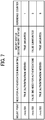
- FIG. 7 is a diagram illustrating a mount information table used by the mount status management unit 152 to manage the information in this embodiment.
- mount information table shown in FIG. 7 , information on "mount point”, “need for authentication in mounting”, “mount status”, and “reference counter” are registered for each storage area mounted in the OS 160.
- mount point that the OS allocates to the target storage area is registered in the "mount point". It is also possible to register information on address and path etc. regarding hardware including the target storage area or used for specifying an area inside the hardware along with the information.
- Information indicating whether or not an authentication operation is required in instructing the OS 160 to mount the target mount point is registered in the "need for authentication in mounting". The information can be registered based on whether or not it is required to execute the authentication operation in requesting the OS 160 to mount actually.
- the number of processes in the data referrer 140 using the target mount point is registered in the "reference counter". The number is counted by the reference counter management unit 153 based on notification from the data reference start notification unit 143 in the data referrer 140 and the data reference finish notification unit 144 in the data referrer 140. If one process refers to multiple files in one mount point, it is possible to count in the way that there are processes that use the mount point for each of the references.
- the mount information table described above it is possible to register the information for each storage area if the OS 160 succeeds in mounting the storage area, and it is possible to delete the information for each storage area if the OS 160 succeeds in unmounting the storage area.
- the storage area whose information is registered in the mount information table is mounted in the OS 160, and the storage area whose information is not registered in the mount information table is not mounted in the OS 160. That is, whether or not it is registered in the mount information table itself indicates information on the first mount status indicating whether or not the storage area is mounted in the OS 160.
- the mount status management unit 152 can manage the first mount status and the second mount status respectively for required storage area. It should be noted that the second mount status cannot be “mounted” if the first mount status is "unmounted". In this case, it is indicated that the storage area that is not mounted actually is mounted to user, and that is inconvenience. Therefore, it is controlled so that the image processing apparatus 100 does not enter into the status described above.
- the reference counter management unit 153 includes a function that counts the number of processes registered in the field "reference counter" in the mount information table as described above. In case of receiving a notification indicating that a storage area is to be accessed from the data reference start notification unit 143, the reference counter management unit 153 increments a count value associated with the storage area. By contrast, in case of receiving a notification indicating that it is finished to access a storage area from the data reference finish notification unit 144, the reference counter management unit 153 decrements a count value associated with the storage area.
- the reference counter management unit 153 includes a function that reports to the unmount need determination unit 155 that the number of processes becomes zero after the decrement.
- the mount need determination unit 154 includes a function that determines whether or not it is required to instruct the OS 160 to perform the mounting operation in accordance with the request to mount. Its judgmental standard is described later with reference to the flowchart in FIG. 8 .
- the unmount need determination unit 155 includes a function that determines whether or not it is required to instruct the OS 160 to perform the unmounting operation in accordance with the request to unmount. Its judgmental standard is described later with reference to the flowchart in FIG. 13 .
- the unmount need determination unit 155 includes a function that determines whether or not it is required to instruct the OS 160 to perform the unmounting operation. Its judgmental standard is described later with reference to the flowchart in FIG. 12 .
- the mount executor 156 includes a function that requests the OS 160 to perform the mounting operation specifying the target storage area. If the request is executed, the mount processor 161 in the OS 160 performs the mounting operation for the specified storage area.
- the mount executor 156 performs necessary requests to the Ul controller 130 to acquire the authentication information input by user operation. Subsequently, the OS 160 is requested to perform the mounting operation along with the authentication information again.
- the unmount executor 157 includes a function that requests the OS 160 to perform the unmounting operation specifying the target storage area. If the request is executed, the unmount processor 162 in the OS 160 performs the unmounting operation for the specified storage area.
- mount executor 156 mount processor 161, unmount executor 157, and unmount processor 162 functions as a mount processing unit. It is also possible to consider that the mount executor 156 and the unmount executor 157 are a mount processing unit that performs the mounting operation and unmounting operation using the functions of the OS 160.
- FIG. 8 is a flowchart illustrating an operation in case of detecting a request to mount by user operation in this embodiment.
- the operation shown in the flowchart in FIG. 8 is executed by the CPU 101 according to a predetermined program, to control hardware to function as the units shown in FIGs. 3 to 6 .
- the command accepting unit 131 After the command accepting unit 131 detects the request to execute the mounting operation from the user, the image processing apparatus 100 starts the operation in the flowchart in FIG. 8 .
- the request to execute the mounting operation includes an instruction on specifying the storage area to be mounted.
- the command accepting unit 131 functions as a mount request accepting unit in accepting the command to execute.
- the image processing apparatus 100 determines whether or not the second mount information "mounted" is registered in the mount information table in FIG. 7 in S11. If information regarding the target storage area itself is not registered in the mount information table, the determination in this case becomes NO. It should be noted that the corresponding relationship between the storage area and the mount point can be obtained through inquiring the OS 160. If the information is registered in the mount information table, it is possible to refer to the mount information table.
- the image processing apparatus 100 determines whether or not the specified storage area has already been mounted (i.e., the information is registered in the mount information table, the first mount information is "mounted") in S12.
- the image processing apparatus 100 performs the operation mounting the specified storage area using the functions of the mount executor 156 and the mount processor 161 in S13.
- the mount management table Based on whether or not authentication is requested in performing the mounting operation, information on whether or not the authentication is required is registered.
- the "mounted" is registered as the second mount status in S15, and the process ends.
- the function of the mount status management unit 152 performs the operation in step S15.
- the image processing apparatus 100 reports to the requester of the mounting operation (i.e., the user in this case) that the mounting operation failed in S16, and the process ends. For example, it is possible to report about failure by displaying a predetermined message.
- the function of the command accepting unit 131 performs the operation in step S16.
- the image processing apparatus 100 determines whether or not authentication is required for the mounting operation of the specified storage area in S17. Such determination may be made based on the information registered in the mount management table.
- the image processing apparatus 100 changes the second mount information on the target storage area in the mount management table into "mounted" in S21, and the process ends.
- the function of the mount status management unit 152 also performs the operation in step S21.
- the image processing apparatus 100 performs the mounting operation for a predetermined storage area for the authentication using the functions of the mount executor 156 and the mount processor 161 in S18. Subsequently, after succeeding in the mounting operation (YES in S19), the unmounting operation is performed for the same storage area using the functions of the unmount executor 157 and the unmount processor 162 in S20, the second mount information is modified in S21, and the process ends.
- the CPU 101 functions as a mount controlling unit (a mount controller).
- the operations in S11, S12, and S17 correspond to the function of the mount need determination unit 154.
- FIG. 9 is a flowchart illustrating an operation in case of detecting a request to display a print request screen by user operation in this embodiment.
- the image processing apparatus 100 After the command accepting unit 131 detects the request to display the print request screen from the user, the image processing apparatus 100 starts the operation in the flowchart in FIG. 9 .
- the image processing apparatus 100 refers to the mount management table and creates a list of printable files stored in a mount point (that mounts a storage area) whose second mount status is "mounted" in S31. Subsequently, based on the created list, a print request screen 400 in FIG. 10 is displayed on a LCD of the UI 104 to accept user operation in S32.
- the print request screen 400 in FIG. 10 is a screen for accepting a request to print a file by user operation, and the print request screen 400 includes a file list field 401, a specified file display field 402, an automatic unmount setting field 403, an OK button 404, and a cancel button 405.
- the file list field 401 displays the list created in S31 in FIG. 9 .
- the file list field 401 displays a file whose second mount status is "mounted", i.e., located in the mount point whose information is presented to the user as "mounted” as a candidate to be printed.
- the information provided to the user is the list of files.
- the command accepting unit 131 functions as a presenting unit.
- the specified file display field 402 displays a file specified as a target to be printed by user operation among the file list field 401.
- the automatic unmount setting field 403 configures whether or not the storage area is unmounted automatically after starting printing requested this time using a check box. In this case, at least the storage area where the file to be printed is stored is unmounted. However, it is possible to unmount all mounted storage areas.
- FIG. 11 is a diagram illustrating a storage area selection screen for selecting a storage area to be referred in this embodiment.
- the storage area selection screen 410 in FIG. 11 includes a storage area list field 411, a specified storage area display field 412, an OK button 414, and a cancel button 415.
- the storage area list field 411 presents a list of paths of storage areas whose second mount status is "mounted", i.e., where the mount point whose information is presented to the user as "mounted” as available storage areas.
- the specified storage area display field 412 displays a storage area specified as a target to be referred by user operation among the storage area list field 411.
- the image processing apparatus 100 updates a displayed screen appropriately in accordance with the operation accepted on the print request screen 400 and waits until the OK button 404 or the cancel button 405 is pressed in S33 and S34.
- the image processing apparatus 100 generates a request to print the file selected as the target to be printed using the function of the operation request unit 135 in S35, and an operation in FIG. 12 is started by passing the request to the corresponding data referrer 140.
- the image processing apparatus 100 if it is configured to unmount automatically in the automatically unmount setting field (YES in S36), the image processing apparatus 100 generates a request to unmount using the function of the unmount request unit 134 in S37, and an operation in FIG. 13 is started by passing the request to the mount management unit 150. It should be noted that the request to unmount is generated after starting printing in accordance the request to print in S35. It is possible to generate the request to unmount under determination of the unmountability determination unit 136 when the operation request consent notification unit 145 reports to the Ul controller 130 that the printing is started.
- the image processing apparatus 100 closes the print request screen in S38, and the process ends. If the cancel button is pressed (YES in S34), steps S35 to S37 are skipped, and the step proceeds to S38.
- the CPU 101 functions as a request accepting unit.
- the CPU 101 functions as a request unit.
- the operations in steps S31 to S34 and S38 correspond to the function of the request accepting unit 131.
- the image processing apparatus 100 it is possible to accept a request to perform operations other than printing using an accepting screen corresponding to the operation in the same way.
- FIG. 12 is a flowchart illustrating an operation in case of detecting a request to print a file stored in a mounted storage area in this embodiment.
- the image processing apparatus 100 After detecting a request to print a file stored in a mounted storage area using the function of the operation request receiver, the image processing apparatus 100 starts the operation shown in the flowchart in FIG. 12 .
- the request is generated in S35 in FIG. 9 .
- the data reference start notification unit 143 and the reference counter management unit 153 increments a reference counter value regarding the storage area where the file to be printed in accordance with the request to print is stored in S51.
- the operation executor 142 starts printing the file requested to be printed in S52. More specifically, after reading the file requested to be printed by accessing the mounted storage area, its data is passed to the print engine 106 to instruct the print engine 106 to print out the data.
- the image processing apparatus 100 waits until it is finished to access the storage area in accordance with printing in S53. Subsequently, after finishing the access, the data reference finish notification unit 144 and the reference counter management unit 153 decrements the reference counter value regarding the storage area where the printed file is stored in S54.
- the unmount need determination unit 155 refers to the mount information table to determine whether or not it is possible to unmount the storage area where the printed file is stored.
- the judgmental standard is that the storage area is not unmounted if the second mount information is "mounted” or the reference counter value is equal to or more than 1 and the storage area is unmounted if the second mount information is "unmounted” and the reference counter value is equal to 0 in S55.
- the image processing apparatus 100 determines that it is inappropriate to unmount the storage area without user permission considering it is finished to use as a trigger.
- the reference counter value is equal to or more than 1, it is considered that another process other than the data referrer 140 that finishes referring this time is referring to the storage area. Therefore, the image processing apparatus 100 determines that it is inappropriate to unmount the storage area at this point. If those conditions are not satisfied, there is no particular problem to unmount the storage area. Therefore, the image processing apparatus 100 determines to unmount the storage area immediately since it could be a problem to maintain the mounting status unnecessarily due to a security requirement.
- the image processing apparatus 100 determines not to unmount the storage area, and the operation in FIG. 12 ends as is.
- NO in S55 it is determined to unmount the storage area.
- the unmount executor 157 and the unmount processor 162 unmount the storage area in S56.
- the mount status management unit 152 deletes the data on the target storage area from the mount management table in S57, and the operation in FIG. 12 ends.
- the CPU 101 functions as an unmount controlling unit (an unmount controller) in the operation in steps S55 to S57 in FIG. 12 .
- the image processing apparatus 100 can perform operations other than printing in accordance with the detected request for operation in the same way. In addition, in performing those operations, it is possible to determine whether or not to unmount a storage area in the same way.
- FIG. 13 is a flowchart illustrating an operation in case of detecting a request to unmount a storage area in this embodiment.
- the operation shown in the flowchart in FIG. 13 starts.
- the request is generated in S37 in FIG. 9 .
- the unmount request unit 134 generates the request in accordance with a request to unmount by user operation accepted by the command accepting unit 131.
- the image processing apparatus 100 performs the operation in FIG. 13 for each of the specified storage areas.
- the mount status management unit 152 sets the second mount status of the storage area specified in the request to unmount to "unmounted" in S61.
- the image processing apparatus 100 presents that the target storage area is unmounted to the user. Therefore, since a request for an operation from the user is accepted assuming that the storage area is unavailable, it is not required to present or acquire data stored in the storage area.
- the unmount need determination unit 155 refers to the mount information table to determine whether or not it is possible to unmount the specified storage area. In this case, it is determined that it is possible to unmount the storage area if the reference counter value of the specified storage area is 0 in S62. That is because it is considered that no process is referring to the storage area and there is no problem with the operation of the apparatus if the storage area is unmounted.
- the unmount executor 157 and the unmount processor 162 unmount the storage area in S63.
- the mount status management unit 152 deletes the data on the target storage area from the mount management table in S64, and the operation in FIG. 13 ends.
- the CPU 101 functions as a mount status updating unit.
- the CPU 101 functions as an executor.
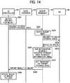
- sequence charts in FIGs. 14 to 17 operations in units of functional units shown in FIG. 3 are illustrated, and operations in units of more detailed functional units shown in FIGs. 4 to 6 are described as needed.
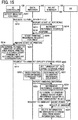
- FIGs. 14 and 15 a first example is illustrated in FIGs. 14 and 15 .
- the image processing apparatus 100 is requested to print a file stored in an external storage device by user operation, and the external storage is not mounted. It is also assumed that no authentication is required to mount the external storage and it is possible to configure unmounting automatically in the print request screen 400 in FIG. 10 .
- the external storage device that stores a file to be printed is connected to the image processing apparatus 100, and the image processing apparatus 100 is requested to mount the external storage device by user operation.
- the command accepting unit 131 in the Ul controller 130 detects this request in S201.
- the mount request unit 133 passes a request to mount specifying the external storage device as the storage area to the mount management unit 150 in S202.
- the command receiver 151 receives the request to mount and reports to the mount need determination unit 154 about that. Since the specified external storage device is not registered in the mount information table (i.e., the first mount status is "unmounted"), the mount need determination unit 154 determines that it is necessary to perform the mounting operation in accordance with the request to mount in S203.
- the mount executor 156 requests the OS 160 to perform the mounting operation in S204.
- the mount processor 161 performs the mounting operation in accordance with the request to mount, and the external storage device is mounted. After that, the OS 160 returns the result of mounting to the mount executor 156 in S205.
- the mount executor 156 reports to the mount status management unit 152 that it is finished to perform the mounting operation.
- the mount status management unit 152 adds data on the external storage device as the newly mounted storage area to the mount information table in S206.
- the second mount information of the target storage area is set to "mounted" in S207.
- the mount executor 156 reports to the mount request unit 133 in the UI controller 130 about the result of mounting in accordance with the request to mount in S202 (i.e., mounting succeeded) in S208.
- the mount request unit 133 reports to the command accepting unit 131 about that, and the command accepting unit 131 displays the result of mounting on the screen to report that to the user in S209.
- the command accepting unit 131 in the UI controller 130 detects this request in S211. Subsequently, the command accepting unit 131 passes the request to the operation request unit 135, and the operation request unit 135 passes a request to print specifying the file to the data referrer 140 that is in charge of printing in S212.
- the operation request receiver 141 receives the request to print and passes the request to print to the data reference start notification unit 143. After that, the data reference start notification unit 143 transfers a notification of starting reference including information on a mount point referred to in printing to the mount management unit 150 in S213.
- the mount management unit 150 After the request receiver 151 receives the notification of starting reference, the reference counter management unit 153 is instructed to increment the reference counter value of the mount point indicated by the notification of starting reference in S214. Subsequently, a response is transferred to the data reference start notification unit 143 in the data referrer 140 in S215.
- the data reference start notification unit 143 After receiving the response, in S216, the data reference start notification unit 143 report to the operation executor 142 that it is possible to access the mounted external storage device and instructs the operation executor 142 to start printing in accordance with the request to print accepted in S212. In addition, the data reference start notification unit 143 reports to the operation request consent notification unit 145 that it is started to print and instructs the operation request consent notification unit 145 to report the operation request unit 135 in the UI controller 130 that it is started to print in S217.
- the operation request unit 135 passes this notification to the unmountability determination unit 136. Based on the notification, the unmountability determination unit 136 determines that it is required to unmount the storage area that stores the file that is started printing since it is started to print in accordance the print request with configuration of "unmounted automatically" in S218. "Unmount" in S218 indicates unmount from viewpoint of the user, and it is possible to achieve that by changing the second mount status into "unmounted” at least.
- the unmountability determination unit 136 After the determination in S218, the unmountability determination unit 136 notifies the unmount request unit 134 of that determination. After receiving the notification, the unmount request unit 134 passes a request to unmount specifying the storage area that stores the file that is started printing to the mount management unit 150 in S219.
- the request receiver 151 receives the request to unmount and passes the request to the mount status management unit 152 to instruct to set the second mount status for the specified storage area to "unmounted” in S220.
- the mount status management unit 152 instructs the unmount need determination unit 155 to determine whether or not it is possible to unmount the specified storage.
- the unmount need determination unit 155 determines that it is unnecessary to unmount the storage area in accordance with the standard in S55 in FIG. 12 in S221. As described above, the operation in accordance with the request to unmount in S219 ends. It is possible that the mount status management unit 152 returns the processing result to the UI controller 130.
- the operation executor 142 in the data referrer 140 notifies the data reference finish notification unit of that. Subsequently, after receiving the notification, the data reference finish notification unit 144 transfers a notification of finishing referring including the information on the mount point referred in printing to the mount management unit 150 in S223.
- the request receiver 151 receives the notification of finishing referring and instructs the reference counter management unit 153 to decrement the reference counter value for the mount point indicated by the notification of finishing referring in S224. As a result, the reference counter value returns to the initial value, i.e., 0.
- the reference counter management unit 153 instructs the unmount need determination unit 155 to determine whether or not it is required to unmount the storage area that is finished referring.
- the unmount need determination unit 155 determines to perform the unmount operation in accordance with the standard in S55 in FIG. 12 in S225.
- the unmount need determination unit 155 notifies the unmount executor 157 of that, and the unmount executor 157 requests the OS 160 to perform the unmounting operation in S226.
- the unmount processor 162 performs the unmounting operation in accordance with the request.
- the external storage device gets unmounted.
- the OS 160 returns the unmounting result to the unmount executor 157 in S227.
- the unmount executor 157 reports to the mount status management unit 152 that it is finished to unmount.
- the mount status management unit 152 deletes data on the external storage device as the unmounted storage area from the mount information table in S228.
- the operation in accordance with the notification of finishing referring to the file in S223 ends. It is possible that the mount status management unit 152 returns the processing result to the data referrer 140. Otherwise, it is possible that the operation executor 142 in the data referrer 140 returns the result of printing to the UI controller 130.
- the first example is described above.
- the mount status management unit 152 manages the first mount status that indicates whether a storage area is mounted or not in accordance with the mounting operation and the unmounting operation in the OS 160 and the second mount status that indicates whether a storage area is mounted or not to be presented to the user respectively.
- FIGs. 16 and 17 a second example is illustrated in FIGs. 16 and 17 .
- the second example is different from the first example in a point that authentication is required in mounting an external storage device.
- steps S301 to S304 are the same as the first example.
- the mount processor 161 in the OS 160 requests the mount executor 156 as the requester to pass authentication information used for the authentication in S305.
- the mount executor 156 requests the command accepting unit 131 in the UI controller 130 to pass the authentication information in S306.
- the command accepting unit 131 After receiving the request, the command accepting unit 131 displays an appropriate screen on the UI 104 to accept the authentication information input by user operation in S307. It is possible to have the user to input data stored in an IC card or biometric information as the authentication information.
- the command accepting unit 131 passes the authentication information accepted from the user to the mount executor 156 in S308.
- the mount executor 156 requests the OS 160 to mount again adding the authentication information.
- mount executor 161 succeeds the user authentication using the authentication information and there is no other problem, it is succeeded to mount.
- Subsequent operations in S310 to S314 are the same as the operations in S205 to S209 in FIG. 14 .
- the mount information table since it is required to perform the authentication in S305, in the mount information table, information indicating that it is required to authenticate in mounting an external storage is registered.
- FIG. 17 is a sequence diagram illustrating an operation that the command accepting unit 131 detects a second request to mount the same external storage device after S220 in FIG. 15 .
- the mount request unit 133 After detecting the request in S321, after the command accepting unit 131 passes this request to the mount request unit 133, the mount request unit 133 passes the request to mount specifying the external storage device as the storage area to the mount management unit 150 in S322.
- the mount need determination unit 154 receives the request via the request receiver. Subsequently, since the specified external storage device is registered in the mount information table in S311 (i.e., the first mount status is "mounted"), it is determined that it is unnecessary to mount in accordance with the request to mount in S323.
- the mount need determination unit 154 determines that it is required to authenticate in mounting the external storage device from the content of the mount information table in S324. As a result, the mount need determination unit 154 determines that it is required to instruct the OS 160 to execute the mounting operation for this authentication.
- each unit performs the mounting operation including the authenticating operation just like the case in steps S305 to S310 in FIG. 16 .
- the mount executor 156 instructs the unmount executor 157 to request the OS 160 to unmount the storage area for checking mounted previously in S332. That is because the storage area cannot be used for checking in the next mounting operation and that can be a risk of security if the storage area for checking is kept mounted.
- the unmount processor 162 in the OS 160 performs the unmounting operation and returns its result in S333.
- the mount executor 156 After the mount executor 156 receives the result via the unmount executor 157, it is possible to present the external storage device as mounted one to the user. Therefore, the mount status management unit 152 is instructed to change the second mount status of the external storage device into "mounted" in S334.
- the mount executor 156 reports to the mount request unit 133 in the UI controller 130 about the result of mounting in accordance with the request to mount in S322 (i.e., mounting succeeded) in S335.
- the mount request unit 133 reports to the command accepting unit 131 about that, and the command accepting unit 131 displays the result of mounting on the screen to report that to the user in S336.
- the second example is described above.
- the request to mount on the storage area whose first mount status is "mounted” and the second mount status is "unmounted” is issued. Since it is presented to the user as if the storage area is not mounted, it is possible to request to mount the storage area by user operation.
- the OS 160 recognizes that the storage area is mounted, it is unnecessary to mount the storage area again actually. Therefore, since it is possible to present to the user as if the mounting operation is finished simply by changing the second mount information, it is possible to omit the mounting operation, reducing processing load and processing time.
- the OS 160 performs the mounting operation on the predetermined storage area for the authentication check, and it is possible to handle as if the storage area specified in the request to mount succeeds in mounting if the mounting operation succeeded.
- the image processing apparatus 100 accepts user requests and user operations performed on the image processing apparatus 100 itself directly. Otherwise, it is possible to accept those user requests and user operations using an external information processing apparatus such as the terminal apparatus 300 etc.
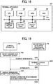
- a known computer that includes a CPU 301, a ROM 302, a RAM 303, a HDD 304, a communication I/F 305, a control panel 306, and a display unit 307 etc. connecting with each other via a system bus 310 as shown in FIG. 18 can be used as the terminal apparatus 300.
- the terminal apparatus 300 accesses the UI controller 130 in the image processing apparatus 100 to acquire screen data in accordance with the request in steps S402 to S404. Subsequently, in the terminal apparatus 300, the display unit 307 displays a screen corresponding to the screen data, user operations to the image processing apparatus 100 are accepted on the screen, and a request for operation in accordance with the accepted user operation is transferred to the image processing apparatus 100 in S406.
- the image processing apparatus 100 can handle the requests for operation just like various user requests accepted in the embodiments described above, and it is possible to perform the operations just like the operations shown in FIGs. 8 to 13 .
- a request for operation accepted by the image processing apparatus 100 is not only a request arising from user operation but also a request generated by a computer automatically.
- functions of the image processing apparatus 100 can be implemented distributing to multiple apparatuses, and it is possible to construct an information processing system or an image processing system that includes functions similar to the image processing apparatus 100 cooperating those multiple apparatuses with each other.
- the information processing apparatus is constructed as the image processing apparatus 100.
- the image processing function is not mandatory. Therefore, it is possible to construct a configuration that a generic computer includes function shown in FIGs. 3 to 6 .
- Programs in the embodiments of the present invention instructs the computer to control the predetermined hardware to implement the functions of the image processing apparatus 100 described in the embodiments.
- an information processing apparatus which notifies a user of a status of mount even while data is being read from the mounted storage area or data is being written in the mounted storage area.
- a computer can be used with a computer-readable program, described by object-oriented programming languages such as C++, C#, Java (registered trademark), or legacy programming languages such as machine language, assembler language, C language to control functional units used for the apparatus or system.
- object-oriented programming languages such as C++, C#, Java (registered trademark)
- legacy programming languages such as machine language, assembler language, C language to control functional units used for the apparatus or system.
- the computer software can be provided to the programmable device using any storage medium or carrier medium for storing processor-readable code such as a floppy disk, a compact disk read only memory (CD-ROM), a digital versatile disk read only memory (DVD-ROM), DVD recording only/rewritable (DVD-R/RW), Blu-ray disc, electrically erasable and programmable read only memory (EEPROM), erasable programmable read only memory (EPROM), a memory card or stick such as USB memory, a memory chip, a mini disk (MD), a magneto optical disc (MO), magnetic tape, a hard disk in a server, a solid state memory device or the like, but not limited these.
- processor-readable code such as a floppy disk, a compact disk read only memory (CD-ROM), a digital versatile disk read only memory (DVD-ROM), DVD recording only/rewritable (DVD-R/RW), Blu-ray disc, electrically erasable and programmable read only memory (EEPROM
- a processing circuit includes a programmed processor, as a processor includes circuitry.
- a processing circuit includes a programmable device (PD) such as a Field Programmable Gate Array (FPGA) for example.
- PD programmable device
- FPGA Field Programmable Gate Array
- a processing circuit also includes devices such as an application specific integrated circuit (ASIC) and conventional circuit components arranged to perform the recited functions. It is also possible to distribute them storing a recording medium as data described in circuit configuration data (bit stream data) downloaded to the PD to implement the functional blocks on the PD, Hardware Description Language (HDL) for generating the circuit configuration data, Very High speed integrated circuits hardware Description Language (VHDL), and Verilog-HDL etc.
- HDL Hardware Description Language
- this invention may be implemented as convenient using a conventional general-purpose digital computer programmed according to the teachings of the present specification.
- Appropriate software coding can readily be prepared by skilled programmers based on the teachings of the present disclosure, as will be apparent to those skilled in the software arts.
- the present invention may also be implemented by the preparation of application-specific integrated circuits or by interconnecting an appropriate network of conventional component circuits, as will be readily apparent to those skilled in the relevant art.
- a processing circuit includes a programmed processor, as a processor includes circuitry.
- a processing circuit also includes devices such as an application specific integrated circuit (ASIC) and conventional circuit components arranged to perform the recited functions.
- ASIC application specific integrated circuit
Landscapes
- Engineering & Computer Science (AREA)
- Theoretical Computer Science (AREA)
- Human Computer Interaction (AREA)
- Physics & Mathematics (AREA)
- General Engineering & Computer Science (AREA)
- General Physics & Mathematics (AREA)
- Computer Security & Cryptography (AREA)
- Facsimiles In General (AREA)
- Storing Facsimile Image Data (AREA)
Claims (10)
- Appareil de traitement d'informations (100), comprenant :une unité de traitement de montage (161) destinée à commander le montage ou le démontage d'une zone de stockage (103) spécifiée sur un système d'exploitation présent sur l'appareil de traitement d'informations (100) ;une unité de présentation (131) destinée à présenter une zone de stockage (103) disponible à un utilisateur ; etune unité de gestion de montage (152) destinée à gérer un premier statut de montage indiquant si une opération de montage et de démontage a été mise en oeuvre ou non sur le système d'exploitation de l'appareil de traitement d'informations (100) et un deuxième statut de montage indiquant si la zone de stockage (103) spécifiée présentée par l'unité de présentation (131) est montée ou non,dans lequel l'unité de présentation (131) présente à l'utilisateur la zone de stockage (103) spécifiée en tant que zone de stockage (103) montée disponible si le deuxième statut de montage indique que la zone de stockage (103) spécifiée est montée, et l'unité de présentation (131) ne présente pas la zone de stockage (103) spécifiée en tant que zone de stockage (103) disponible si le deuxième statut de montage indique que la zone de stockage (103) n'est pas montée, l'appareil (100) comprenant en outre :une unité d'acceptation de requête de démontage (151) destinée à accepter une requête de démontage de la zone de stockage (103) spécifiée ;un dispositif d'exécution (101) destiné à donner l'ordre à l'unité de traitement de montage (161) de démonter la zone de stockage (103) spécifiée conformément à la requête acceptée par l'unité d'acceptation de requête de démontage (151); etune unité de mise à jour de statut de montage (101) destinée à définir le deuxième statut de montage de la zone de stockage (103) spécifiée comme étant « démontée » avant que l'unité de traitement de montage (161) ne démonte la zone de stockage (103) spécifiée.
- Appareil de traitement d'informations selon la revendication 1, dans lequel l'unité de mise à jour de statut de montage est configurée pour placer le deuxième statut de montage de la zone de stockage (103) spécifiée comme étant « démontée » si l'unité de traitement de montage (161) ne peut démonter la zone de stockage (103) spécifiée.
- Appareil de traitement d'informations (100) selon la revendication 1 ou 2, dans lequel l'unité d'acceptation de requête de démontage (151) comprend une unité d'acceptation (131) destinée à accepter la requête de démontage grâce à une opération d'utilisateur.
- Appareil de traitement d'informations (100) selon l'une quelconque des revendications 1, 2 ou 3, comprenant en outre :une unité d'acceptation de requête d'opération (131) destinée à accepter une requête d'accès à l'une des zones de stockage (103) montées disponibles ; etune unité de requête (101) destinée à demander à l'unité d'acceptation de requête de démontage (151) de mettre en oeuvre l'opération de démontage sur la zone de stockage (103) montée disponible spécifiée dans la requête d'accès.
- Appareil de traitement d'informations (100) selon l'une quelconque des revendications 1 à 4, comprenant en outre :un compteur (153) destiné à compter un nombre de procédures utilisant respectivement la zone de stockage (103) montée disponible ; etune unité de commande de démontage (101) destinée à donner l'ordre à l'unité de traitement de montage (161) de démonter la zone de stockage (103) lorsque le nombre compté de procédures utilisant la zone de stockage (103) devient nul.
- Appareil de traitement d'informations (100) selon la revendication 5, dans lequel l'unité de commande de démontage (101) donne l'ordre à l'unité de traitement de montage (161) de démonter la zone de stockage (103) lorsque le deuxième statut de montage de la zone de stockage (103) devient « démontée », en plus du fait que le nombre compté de procédures utilisant la zone de stockage (103) devient nul.
- Appareil de traitement d'informations (100) selon l'une quelconque des revendications 1 à 6, comprenant en outre :une unité d'acceptation de requête de montage (131) destinée à accepter une requête de montage d'une zone de stockage (103) ; etune unité de commande de montage (101) destinée à définir le deuxième statut de montage comme étant « démontée » au lieu de donner l'ordre à l'unité de traitement de montage (161) de monter la zone de stockage (103) de manière redondante si le premier statut de montage de la zone de stockage (103) spécifiée dans la requête de montage est « montée ».
- Appareil de traitement d'informations (100) selon la revendication 7, dans lequel l'unité de commande de montage (101) donne l'ordre à l'unité de traitement de montage (161) de monter une zone de stockage prédéterminée en vue d'une authentification si le premier statut de montage de la zone de stockage (103) spécifiée dans la requête de montage est « montée » et s'il est détecté qu'une authentification est requise pour monter la zone de stockage (103) spécifiée en réaction au fait que l'unité d'acceptation de requête de montage (131) reçoit la requête de monter, et l'unité de commande de montage (101) définit le deuxième statut de montage de la zone de stockage (103) spécifiée comme étant « montée » en cas de succès du montage de la zone de stockage (103).
- Procédé de traitement d'informations, mis en oeuvre grâce à un appareil de traitement d'informations (100), le procédé comprenant les étapes consistant à :commander, grâce à une unité de traitement de montage (161), le montage ou le démontage d'une zone de stockage (103) spécifiée sur un système d'exploitation de l'appareil de traitement d'informations (100) ;présenter une zone de stockage (103) disponible à un utilisateur ;gérer un premier statut de montage indiquant si une opération de montage ou de démontage est mise en oeuvre ou non sur le système d'exploitation de l'appareil de traitement d'informations (100), et un deuxième statut de montage indiquant si la zone de stockage (103) spécifiée est montée ou non ;présenter la zone de stockage (103) en tant que zone de stockage (103) disponible si le deuxième statut de montage indique que la zone de stockage (103) est montée ;présenter la zone de stockage (103) en tant que zone de stockage (103) indisponible si le deuxième statut de montage indique que la zone de stockage (103) n'est pas montée ;accepter une requête de démontage de la zone de stockage (103) spécifiée ;donner l'ordre à l'unité de traitement de montage (161) de démonter la zone de stockage (103) spécifiée conformément à la requête ; etdéfinir le deuxième statut de montage de la zone de stockage (103) spécifiée comme étant « démontée » avant que l'unité de traitement de montage (161) démonte la zone de stockage (103) spécifiée.
- Support contenant un code pouvant être lu par un ordinateur afin de commander la mise en oeuvre par ledit ordinateur du procédé selon la revendication 9.
Applications Claiming Priority (1)
| Application Number | Priority Date | Filing Date | Title |
|---|---|---|---|
| JP2015058393A JP2016177642A (ja) | 2015-03-20 | 2015-03-20 | 情報処理装置、情報処理システム、プログラム及び画像処理システム |
Publications (2)
| Publication Number | Publication Date |
|---|---|
| EP3070592A1 EP3070592A1 (fr) | 2016-09-21 |
| EP3070592B1 true EP3070592B1 (fr) | 2018-10-03 |
Family
ID=55586158
Family Applications (1)
| Application Number | Title | Priority Date | Filing Date |
|---|---|---|---|
| EP16159968.3A Not-in-force EP3070592B1 (fr) | 2015-03-20 | 2016-03-11 | Appareil et procédé de traitement d'informations et support de stockage |
Country Status (3)
| Country | Link |
|---|---|
| US (1) | US10162539B2 (fr) |
| EP (1) | EP3070592B1 (fr) |
| JP (1) | JP2016177642A (fr) |
Families Citing this family (3)
| Publication number | Priority date | Publication date | Assignee | Title |
|---|---|---|---|---|
| JP2019096994A (ja) * | 2017-11-21 | 2019-06-20 | キヤノン株式会社 | 情報処理装置、情報処理方法及びプログラム |
| US10963179B2 (en) * | 2019-01-29 | 2021-03-30 | International Business Machines Corporation | Accidental-volume-removal prevention |
| JP2024000887A (ja) * | 2022-06-21 | 2024-01-09 | 株式会社バッファロー | 情報処理装置及びプログラム |
Family Cites Families (19)
| Publication number | Priority date | Publication date | Assignee | Title |
|---|---|---|---|---|
| JPH06282965A (ja) * | 1993-03-26 | 1994-10-07 | Sony Corp | ビデオ編集装置 |
| US20020188697A1 (en) * | 2001-06-08 | 2002-12-12 | O'connor Michael A. | A method of allocating storage in a storage area network |
| US6944793B1 (en) * | 2001-10-29 | 2005-09-13 | Red Hat, Inc. | Method of remote monitoring |
| JP3944449B2 (ja) * | 2002-12-19 | 2007-07-11 | 株式会社日立製作所 | 計算機システム、磁気ディスク装置、および、ディスクキャッシュ制御方法 |
| US8850132B1 (en) * | 2004-12-08 | 2014-09-30 | Symantec Operating Corporation | Method and system for providing a shared data resource coordinator within a storage virtualizing data processing system |
| US7941621B1 (en) * | 2007-03-30 | 2011-05-10 | Symantec Corporation | Automatically mounting and unmounting a volume during a backup or restore operation |
| JP2009087124A (ja) * | 2007-10-01 | 2009-04-23 | Buffalo Inc | 記憶デバイス及び記憶デバイスアクセス制御方法 |
| JP5015046B2 (ja) * | 2008-03-17 | 2012-08-29 | 株式会社リコー | 情報処理装置及び情報処理方法 |
| JP5578793B2 (ja) * | 2009-02-17 | 2014-08-27 | キヤノン株式会社 | 情報処理装置、制御方法、及びプログラム |
| JP5566054B2 (ja) * | 2009-06-24 | 2014-08-06 | キヤノン株式会社 | 情報処理装置、情報処理装置の制御方法、及びプログラム |
| TWI497403B (zh) * | 2010-02-12 | 2015-08-21 | Phison Electronics Corp | 可分區管理儲存系統及其使用方法、管理方法與其控制器 |
| US20140229414A1 (en) * | 2013-02-08 | 2014-08-14 | Ebay Inc. | Systems and methods for detecting anomalies |
| JP6056554B2 (ja) * | 2013-03-04 | 2017-01-11 | 日本電気株式会社 | クラスタシステム |
| JP5790723B2 (ja) * | 2013-09-12 | 2015-10-07 | 日本電気株式会社 | クラスタシステム、情報処理装置、クラスタシステムの制御方法及びプログラム |
| US9256370B2 (en) * | 2013-12-05 | 2016-02-09 | International Business Machines Corporation | Average response time improvement from a file system for a tape library |
| US9753804B1 (en) * | 2014-02-07 | 2017-09-05 | American Megatrends, Inc. | Multi-redundant digital signage |
| US9542106B2 (en) * | 2014-04-02 | 2017-01-10 | International Business Machines Corporation | Efficient repository ingest of a target volume without breaking a flashcopy chain |
| GB2531074A (en) * | 2014-10-10 | 2016-04-13 | Ibm | Storage system and method for operating a storage system |
| CN104571964A (zh) * | 2015-01-15 | 2015-04-29 | 宇龙计算机通信科技(深圳)有限公司 | 基于双系统的外部存储设备的挂载方法及系统 |
-
2015
- 2015-03-20 JP JP2015058393A patent/JP2016177642A/ja active Pending
-
2016
- 2016-03-11 EP EP16159968.3A patent/EP3070592B1/fr not_active Not-in-force
- 2016-03-17 US US15/072,733 patent/US10162539B2/en not_active Expired - Fee Related
Non-Patent Citations (1)
| Title |
|---|
| None * |
Also Published As
| Publication number | Publication date |
|---|---|
| US10162539B2 (en) | 2018-12-25 |
| EP3070592A1 (fr) | 2016-09-21 |
| US20160274807A1 (en) | 2016-09-22 |
| JP2016177642A (ja) | 2016-10-06 |
Similar Documents
| Publication | Publication Date | Title |
|---|---|---|
| US8286167B2 (en) | Image processing apparatus, job management method, and storage medium | |
| US20060230261A1 (en) | Device driver customizing method, program, recording medium and information processing device | |
| US8144346B2 (en) | Apparatus and method for controlling a device with a device driver | |
| US9612818B2 (en) | Information processing apparatus, program management method for information processing apparatus, and non-transitory computer-readable storage medium | |
| JP7439501B2 (ja) | 電子機器、情報処理システム、情報処理方法およびプログラム | |
| JP5423746B2 (ja) | 画像処理装置、アクセス制御方法およびプログラム | |
| US9207899B2 (en) | Management apparatus, system, and method of controlling the same | |
| JP7408931B2 (ja) | 電子機器、情報処理システム、情報処理方法およびプログラム | |
| JP6225586B2 (ja) | 出力システム、端末装置、プログラム及び出力方法 | |
| US20050141020A1 (en) | Image-forming system, display-control method, storage medium storing computer-readable program, and program | |
| JP2017021647A (ja) | プログラム、情報処理装置、インストールシステムおよびインストール方法 | |
| EP3070592A1 (fr) | Appareil et procédé de traitement d'informations et support de stockage | |
| JP4981936B2 (ja) | インストーラ及びプリンタドライバのインストール方法 | |
| US12106002B2 (en) | Display apparatus capable of displaying slide show, method for controlling the same, and storage medium | |
| US9407785B2 (en) | Processing apparatus, processing method and computer-readable storage medium | |
| US12105790B2 (en) | Information processing apparatus, method, and program storage medium | |
| AU2015201626A1 (en) | Operation screen providing system, relay apparatus, operation screen providing apparatus, operation screen providing method and program | |
| JP5178319B2 (ja) | アプリケーションプラットフォーム | |
| US20130067452A1 (en) | Management server, host device, and application management method | |
| US9323907B2 (en) | Distribution apparatus, device, control method for distribution apparatus, and storage medium | |
| EP3557467A1 (fr) | Dispositif de traitement d'informations, dispositif de formation d'images, système de formation d'images et procédé de vérification de virus | |
| JP2017117235A (ja) | 管理プログラム、管理システム、情報処理装置 | |
| KR20240046851A (ko) | 화상 형성 장치, 화상 형성 장치의 제어 방법 및 저장 매체 | |
| JP2014013427A (ja) | 情報処理装置、プログラム及びシステム | |
| US11076062B2 (en) | Information processing device capable of switching language of name of icon, method of controlling information processing device, and a non-transitory computer-readable storage medium |
Legal Events
| Date | Code | Title | Description |
|---|---|---|---|
| PUAI | Public reference made under article 153(3) epc to a published international application that has entered the european phase |
Free format text: ORIGINAL CODE: 0009012 |
|
| 17P | Request for examination filed |
Effective date: 20160311 |
|
| AK | Designated contracting states |
Kind code of ref document: A1 Designated state(s): AL AT BE BG CH CY CZ DE DK EE ES FI FR GB GR HR HU IE IS IT LI LT LU LV MC MK MT NL NO PL PT RO RS SE SI SK SM TR |
|
| AX | Request for extension of the european patent |
Extension state: BA ME |
|
| RIC1 | Information provided on ipc code assigned before grant |
Ipc: G06F 3/12 20060101ALI20180313BHEP Ipc: G06F 3/06 20060101AFI20180313BHEP |
|
| GRAP | Despatch of communication of intention to grant a patent |
Free format text: ORIGINAL CODE: EPIDOSNIGR1 |
|
| STAA | Information on the status of an ep patent application or granted ep patent |
Free format text: STATUS: GRANT OF PATENT IS INTENDED |
|
| INTG | Intention to grant announced |
Effective date: 20180423 |
|
| GRAS | Grant fee paid |
Free format text: ORIGINAL CODE: EPIDOSNIGR3 |
|
| GRAA | (expected) grant |
Free format text: ORIGINAL CODE: 0009210 |
|
| STAA | Information on the status of an ep patent application or granted ep patent |
Free format text: STATUS: THE PATENT HAS BEEN GRANTED |
|
| AK | Designated contracting states |
Kind code of ref document: B1 Designated state(s): AL AT BE BG CH CY CZ DE DK EE ES FI FR GB GR HR HU IE IS IT LI LT LU LV MC MK MT NL NO PL PT RO RS SE SI SK SM TR |
|
| REG | Reference to a national code |
Ref country code: GB Ref legal event code: FG4D |
|
| REG | Reference to a national code |
Ref country code: CH Ref legal event code: EP Ref country code: AT Ref legal event code: REF Ref document number: 1049333 Country of ref document: AT Kind code of ref document: T Effective date: 20181015 |
|
| REG | Reference to a national code |
Ref country code: DE Ref legal event code: R096 Ref document number: 602016006134 Country of ref document: DE Ref country code: IE Ref legal event code: FG4D |
|
| REG | Reference to a national code |
Ref country code: NL Ref legal event code: MP Effective date: 20181003 |
|
| REG | Reference to a national code |
Ref country code: LT Ref legal event code: MG4D |
|
| REG | Reference to a national code |
Ref country code: AT Ref legal event code: MK05 Ref document number: 1049333 Country of ref document: AT Kind code of ref document: T Effective date: 20181003 |
|
| PG25 | Lapsed in a contracting state [announced via postgrant information from national office to epo] |
Ref country code: NL Free format text: LAPSE BECAUSE OF FAILURE TO SUBMIT A TRANSLATION OF THE DESCRIPTION OR TO PAY THE FEE WITHIN THE PRESCRIBED TIME-LIMIT Effective date: 20181003 |
|
| PG25 | Lapsed in a contracting state [announced via postgrant information from national office to epo] |
Ref country code: ES Free format text: LAPSE BECAUSE OF FAILURE TO SUBMIT A TRANSLATION OF THE DESCRIPTION OR TO PAY THE FEE WITHIN THE PRESCRIBED TIME-LIMIT Effective date: 20181003 Ref country code: LV Free format text: LAPSE BECAUSE OF FAILURE TO SUBMIT A TRANSLATION OF THE DESCRIPTION OR TO PAY THE FEE WITHIN THE PRESCRIBED TIME-LIMIT Effective date: 20181003 Ref country code: PL Free format text: LAPSE BECAUSE OF FAILURE TO SUBMIT A TRANSLATION OF THE DESCRIPTION OR TO PAY THE FEE WITHIN THE PRESCRIBED TIME-LIMIT Effective date: 20181003 Ref country code: HR Free format text: LAPSE BECAUSE OF FAILURE TO SUBMIT A TRANSLATION OF THE DESCRIPTION OR TO PAY THE FEE WITHIN THE PRESCRIBED TIME-LIMIT Effective date: 20181003 Ref country code: BG Free format text: LAPSE BECAUSE OF FAILURE TO SUBMIT A TRANSLATION OF THE DESCRIPTION OR TO PAY THE FEE WITHIN THE PRESCRIBED TIME-LIMIT Effective date: 20190103 Ref country code: NO Free format text: LAPSE BECAUSE OF FAILURE TO SUBMIT A TRANSLATION OF THE DESCRIPTION OR TO PAY THE FEE WITHIN THE PRESCRIBED TIME-LIMIT Effective date: 20190103 Ref country code: IS Free format text: LAPSE BECAUSE OF FAILURE TO SUBMIT A TRANSLATION OF THE DESCRIPTION OR TO PAY THE FEE WITHIN THE PRESCRIBED TIME-LIMIT Effective date: 20190203 Ref country code: FI Free format text: LAPSE BECAUSE OF FAILURE TO SUBMIT A TRANSLATION OF THE DESCRIPTION OR TO PAY THE FEE WITHIN THE PRESCRIBED TIME-LIMIT Effective date: 20181003 Ref country code: LT Free format text: LAPSE BECAUSE OF FAILURE TO SUBMIT A TRANSLATION OF THE DESCRIPTION OR TO PAY THE FEE WITHIN THE PRESCRIBED TIME-LIMIT Effective date: 20181003 Ref country code: AT Free format text: LAPSE BECAUSE OF FAILURE TO SUBMIT A TRANSLATION OF THE DESCRIPTION OR TO PAY THE FEE WITHIN THE PRESCRIBED TIME-LIMIT Effective date: 20181003 Ref country code: CZ Free format text: LAPSE BECAUSE OF FAILURE TO SUBMIT A TRANSLATION OF THE DESCRIPTION OR TO PAY THE FEE WITHIN THE PRESCRIBED TIME-LIMIT Effective date: 20181003 |
|
| PG25 | Lapsed in a contracting state [announced via postgrant information from national office to epo] |
Ref country code: SE Free format text: LAPSE BECAUSE OF FAILURE TO SUBMIT A TRANSLATION OF THE DESCRIPTION OR TO PAY THE FEE WITHIN THE PRESCRIBED TIME-LIMIT Effective date: 20181003 Ref country code: RS Free format text: LAPSE BECAUSE OF FAILURE TO SUBMIT A TRANSLATION OF THE DESCRIPTION OR TO PAY THE FEE WITHIN THE PRESCRIBED TIME-LIMIT Effective date: 20181003 Ref country code: PT Free format text: LAPSE BECAUSE OF FAILURE TO SUBMIT A TRANSLATION OF THE DESCRIPTION OR TO PAY THE FEE WITHIN THE PRESCRIBED TIME-LIMIT Effective date: 20190203 Ref country code: GR Free format text: LAPSE BECAUSE OF FAILURE TO SUBMIT A TRANSLATION OF THE DESCRIPTION OR TO PAY THE FEE WITHIN THE PRESCRIBED TIME-LIMIT Effective date: 20190104 Ref country code: AL Free format text: LAPSE BECAUSE OF FAILURE TO SUBMIT A TRANSLATION OF THE DESCRIPTION OR TO PAY THE FEE WITHIN THE PRESCRIBED TIME-LIMIT Effective date: 20181003 |
|
| REG | Reference to a national code |
Ref country code: DE Ref legal event code: R097 Ref document number: 602016006134 Country of ref document: DE |
|
| PG25 | Lapsed in a contracting state [announced via postgrant information from national office to epo] |
Ref country code: DK Free format text: LAPSE BECAUSE OF FAILURE TO SUBMIT A TRANSLATION OF THE DESCRIPTION OR TO PAY THE FEE WITHIN THE PRESCRIBED TIME-LIMIT Effective date: 20181003 Ref country code: IT Free format text: LAPSE BECAUSE OF FAILURE TO SUBMIT A TRANSLATION OF THE DESCRIPTION OR TO PAY THE FEE WITHIN THE PRESCRIBED TIME-LIMIT Effective date: 20181003 |
|
| PLBE | No opposition filed within time limit |
Free format text: ORIGINAL CODE: 0009261 |
|
| STAA | Information on the status of an ep patent application or granted ep patent |
Free format text: STATUS: NO OPPOSITION FILED WITHIN TIME LIMIT |
|
| PG25 | Lapsed in a contracting state [announced via postgrant information from national office to epo] |
Ref country code: SK Free format text: LAPSE BECAUSE OF FAILURE TO SUBMIT A TRANSLATION OF THE DESCRIPTION OR TO PAY THE FEE WITHIN THE PRESCRIBED TIME-LIMIT Effective date: 20181003 Ref country code: EE Free format text: LAPSE BECAUSE OF FAILURE TO SUBMIT A TRANSLATION OF THE DESCRIPTION OR TO PAY THE FEE WITHIN THE PRESCRIBED TIME-LIMIT Effective date: 20181003 Ref country code: SM Free format text: LAPSE BECAUSE OF FAILURE TO SUBMIT A TRANSLATION OF THE DESCRIPTION OR TO PAY THE FEE WITHIN THE PRESCRIBED TIME-LIMIT Effective date: 20181003 Ref country code: RO Free format text: LAPSE BECAUSE OF FAILURE TO SUBMIT A TRANSLATION OF THE DESCRIPTION OR TO PAY THE FEE WITHIN THE PRESCRIBED TIME-LIMIT Effective date: 20181003 |
|
| 26N | No opposition filed |
Effective date: 20190704 |
|
| PG25 | Lapsed in a contracting state [announced via postgrant information from national office to epo] |
Ref country code: SI Free format text: LAPSE BECAUSE OF FAILURE TO SUBMIT A TRANSLATION OF THE DESCRIPTION OR TO PAY THE FEE WITHIN THE PRESCRIBED TIME-LIMIT Effective date: 20181003 Ref country code: MC Free format text: LAPSE BECAUSE OF FAILURE TO SUBMIT A TRANSLATION OF THE DESCRIPTION OR TO PAY THE FEE WITHIN THE PRESCRIBED TIME-LIMIT Effective date: 20181003 |
|
| REG | Reference to a national code |
Ref country code: CH Ref legal event code: PL |
|
| PG25 | Lapsed in a contracting state [announced via postgrant information from national office to epo] |
Ref country code: LU Free format text: LAPSE BECAUSE OF NON-PAYMENT OF DUE FEES Effective date: 20190311 |
|
| REG | Reference to a national code |
Ref country code: BE Ref legal event code: MM Effective date: 20190331 |
|
| PG25 | Lapsed in a contracting state [announced via postgrant information from national office to epo] |
Ref country code: IE Free format text: LAPSE BECAUSE OF NON-PAYMENT OF DUE FEES Effective date: 20190311 Ref country code: LI Free format text: LAPSE BECAUSE OF NON-PAYMENT OF DUE FEES Effective date: 20190331 Ref country code: CH Free format text: LAPSE BECAUSE OF NON-PAYMENT OF DUE FEES Effective date: 20190331 |
|
| PG25 | Lapsed in a contracting state [announced via postgrant information from national office to epo] |
Ref country code: BE Free format text: LAPSE BECAUSE OF NON-PAYMENT OF DUE FEES Effective date: 20190331 |
|
| PG25 | Lapsed in a contracting state [announced via postgrant information from national office to epo] |
Ref country code: TR Free format text: LAPSE BECAUSE OF FAILURE TO SUBMIT A TRANSLATION OF THE DESCRIPTION OR TO PAY THE FEE WITHIN THE PRESCRIBED TIME-LIMIT Effective date: 20181003 |
|
| PGFP | Annual fee paid to national office [announced via postgrant information from national office to epo] |
Ref country code: GB Payment date: 20200323 Year of fee payment: 5 Ref country code: DE Payment date: 20200320 Year of fee payment: 5 |
|
| PG25 | Lapsed in a contracting state [announced via postgrant information from national office to epo] |
Ref country code: MT Free format text: LAPSE BECAUSE OF NON-PAYMENT OF DUE FEES Effective date: 20190311 |
|
| PGFP | Annual fee paid to national office [announced via postgrant information from national office to epo] |
Ref country code: FR Payment date: 20200320 Year of fee payment: 5 |
|
| PG25 | Lapsed in a contracting state [announced via postgrant information from national office to epo] |
Ref country code: CY Free format text: LAPSE BECAUSE OF FAILURE TO SUBMIT A TRANSLATION OF THE DESCRIPTION OR TO PAY THE FEE WITHIN THE PRESCRIBED TIME-LIMIT Effective date: 20181003 |
|
| PG25 | Lapsed in a contracting state [announced via postgrant information from national office to epo] |
Ref country code: HU Free format text: LAPSE BECAUSE OF FAILURE TO SUBMIT A TRANSLATION OF THE DESCRIPTION OR TO PAY THE FEE WITHIN THE PRESCRIBED TIME-LIMIT; INVALID AB INITIO Effective date: 20160311 |
|
| REG | Reference to a national code |
Ref country code: DE Ref legal event code: R119 Ref document number: 602016006134 Country of ref document: DE |
|
| GBPC | Gb: european patent ceased through non-payment of renewal fee |
Effective date: 20210311 |
|
| PG25 | Lapsed in a contracting state [announced via postgrant information from national office to epo] |
Ref country code: DE Free format text: LAPSE BECAUSE OF NON-PAYMENT OF DUE FEES Effective date: 20211001 Ref country code: FR Free format text: LAPSE BECAUSE OF NON-PAYMENT OF DUE FEES Effective date: 20210331 Ref country code: GB Free format text: LAPSE BECAUSE OF NON-PAYMENT OF DUE FEES Effective date: 20210311 |
|
| PG25 | Lapsed in a contracting state [announced via postgrant information from national office to epo] |
Ref country code: MK Free format text: LAPSE BECAUSE OF FAILURE TO SUBMIT A TRANSLATION OF THE DESCRIPTION OR TO PAY THE FEE WITHIN THE PRESCRIBED TIME-LIMIT Effective date: 20181003 |