EP3069186B1 - Vorrichtung und verfahren zur führung eines laserstrahls - Google Patents
Vorrichtung und verfahren zur führung eines laserstrahls Download PDFInfo
- Publication number
- EP3069186B1 EP3069186B1 EP14777308.9A EP14777308A EP3069186B1 EP 3069186 B1 EP3069186 B1 EP 3069186B1 EP 14777308 A EP14777308 A EP 14777308A EP 3069186 B1 EP3069186 B1 EP 3069186B1
- Authority
- EP
- European Patent Office
- Prior art keywords
- laser beam
- arrangement
- angle
- workpiece
- mirrors
- Prior art date
- Legal status (The legal status is an assumption and is not a legal conclusion. Google has not performed a legal analysis and makes no representation as to the accuracy of the status listed.)
- Active
Links
Images


Classifications
-
- G—PHYSICS
- G02—OPTICS
- G02B—OPTICAL ELEMENTS, SYSTEMS OR APPARATUS
- G02B26/00—Optical devices or arrangements for the control of light using movable or deformable optical elements
- G02B26/08—Optical devices or arrangements for the control of light using movable or deformable optical elements for controlling the direction of light
- G02B26/10—Scanning systems
- G02B26/105—Scanning systems with one or more pivoting mirrors or galvano-mirrors
-
- B—PERFORMING OPERATIONS; TRANSPORTING
- B23—MACHINE TOOLS; METAL-WORKING NOT OTHERWISE PROVIDED FOR
- B23K—SOLDERING OR UNSOLDERING; WELDING; CLADDING OR PLATING BY SOLDERING OR WELDING; CUTTING BY APPLYING HEAT LOCALLY, e.g. FLAME CUTTING; WORKING BY LASER BEAM
- B23K26/00—Working by laser beam, e.g. welding, cutting or boring
- B23K26/02—Positioning or observing the workpiece, e.g. with respect to the point of impact; Aligning, aiming or focusing the laser beam
- B23K26/03—Observing, e.g. monitoring, the workpiece
- B23K26/032—Observing, e.g. monitoring, the workpiece using optical means
-
- B—PERFORMING OPERATIONS; TRANSPORTING
- B23—MACHINE TOOLS; METAL-WORKING NOT OTHERWISE PROVIDED FOR
- B23K—SOLDERING OR UNSOLDERING; WELDING; CLADDING OR PLATING BY SOLDERING OR WELDING; CUTTING BY APPLYING HEAT LOCALLY, e.g. FLAME CUTTING; WORKING BY LASER BEAM
- B23K26/00—Working by laser beam, e.g. welding, cutting or boring
- B23K26/02—Positioning or observing the workpiece, e.g. with respect to the point of impact; Aligning, aiming or focusing the laser beam
- B23K26/06—Shaping the laser beam, e.g. by masks or multi-focusing
- B23K26/064—Shaping the laser beam, e.g. by masks or multi-focusing by means of optical elements, e.g. lenses, mirrors or prisms
- B23K26/0643—Shaping the laser beam, e.g. by masks or multi-focusing by means of optical elements, e.g. lenses, mirrors or prisms comprising mirrors
-
- B—PERFORMING OPERATIONS; TRANSPORTING
- B23—MACHINE TOOLS; METAL-WORKING NOT OTHERWISE PROVIDED FOR
- B23K—SOLDERING OR UNSOLDERING; WELDING; CLADDING OR PLATING BY SOLDERING OR WELDING; CUTTING BY APPLYING HEAT LOCALLY, e.g. FLAME CUTTING; WORKING BY LASER BEAM
- B23K26/00—Working by laser beam, e.g. welding, cutting or boring
- B23K26/02—Positioning or observing the workpiece, e.g. with respect to the point of impact; Aligning, aiming or focusing the laser beam
- B23K26/06—Shaping the laser beam, e.g. by masks or multi-focusing
- B23K26/0665—Shaping the laser beam, e.g. by masks or multi-focusing by beam condensation on the workpiece, e.g. for focusing
-
- B—PERFORMING OPERATIONS; TRANSPORTING
- B23—MACHINE TOOLS; METAL-WORKING NOT OTHERWISE PROVIDED FOR
- B23K—SOLDERING OR UNSOLDERING; WELDING; CLADDING OR PLATING BY SOLDERING OR WELDING; CUTTING BY APPLYING HEAT LOCALLY, e.g. FLAME CUTTING; WORKING BY LASER BEAM
- B23K26/00—Working by laser beam, e.g. welding, cutting or boring
- B23K26/36—Removing material
- B23K26/38—Removing material by boring or cutting
- B23K26/382—Removing material by boring or cutting by boring
-
- G—PHYSICS
- G02—OPTICS
- G02B—OPTICAL ELEMENTS, SYSTEMS OR APPARATUS
- G02B26/00—Optical devices or arrangements for the control of light using movable or deformable optical elements
- G02B26/08—Optical devices or arrangements for the control of light using movable or deformable optical elements for controlling the direction of light
- G02B26/10—Scanning systems
- G02B26/101—Scanning systems with both horizontal and vertical deflecting means, e.g. raster or XY scanners
Definitions
- the invention relates to a device for guiding a laser beam for processing a workpiece with a mirror arrangement with movable mirrors for generating an angle of attack of the laser beam on a focusing optics for adjusting a lateral offset of the laser beam on the workpiece and for generating a lateral offset of the laser beam on the focusing Optics for adjusting the angle of incidence of the laser beam on the workpiece.
- the invention further relates to a method for guiding a laser beam for processing a workpiece, using a mirror arrangement with movable mirrors to set an angle of attack of the laser beam on a focusing optics to adjust a lateral offset of the laser beam on the workpiece and a lateral offset of the laser beam on the focusing optics is generated to adjust an impact angle of the laser beam on the workpiece and the laser beam is guided over the workpiece at predetermined angles on predetermined paths running around an optical axis by corresponding movement of the mirrors.
- Such a device is from the WO 2006/021442 known.
- the document describes a scan head as part of a laser drilling and cutting device with a series of the following components arranged in the light path of the laser: an intensity-regulating beam attenuation unit in conjunction with a tumbling unit that regulates a parallel beam displacement, a beam expander telescope that enlarges the beam cross section of the laser, a scanning block that guides the focus of the laser beam and a working unit that focuses the laser beam on the sample, as well as additional testing devices that can optionally be coupled into the light path. and control units.
- the wobble unit is made up of two plane-parallel, rotatable windows and enables a lateral offset of a passing laser beam.
- the laser beam follows a closed path around the optical axis.
- the lateral offset and thus the diameter of the closed path is increased by the beam expander telescope.
- the focus of the laser beam can be shifted in the direction of propagation using the beam expander telescope.
- the beam offset directs the laser beam outside the optical axis onto the focusing work unit, so that the laser beam hits the workpiece to be machined after the work unit at an angle that depends on the set offset.
- the scanning block arranged after the beam expander telescope deflects the laser beam in an X or Y direction using a mirror arrangement.
- the laser beam hitting the focusing work unit at an angle hits the workpiece outside the optical axis.
- the wobble unit and the subsequent beam expander telescope determine the angle of incidence of the laser beam on the workpiece, while the mirror arrangement of the scanning block enables the laser beam to be offset laterally on the workpiece.
- the laser beam is directed onto the workpiece at predetermined angles on a closed path that can be specified in its course by the scanning block, rotating around the optical axis. This makes it possible, for example, to drill holes with geometries that deviate from the round shape and with negative taper.
- the large scanning mirror required in the scanning block is the large one required in the systems constructed, since the beam has already been expanded and laterally offset by the beam expander telescope. Furthermore, the rotating windows of the wobble unit require very large scanning angles or thick windows with high inertia in order to generate the necessary beam offset. Both requirements lead to a significant limitation of the dynamics of the system. The size of the scanning mirror still requires a compromise between the maximum angle of attack and the achievable dynamics. This means that in typical systems the maximum angle of attack is limited to approx. 5°. Another disadvantage of the tumbling unit constructed with two rotating windows is a focus shift caused by temperature fluctuations.
- the object of the invention is achieved by a device for guiding a laser beam according to claim 1, and by a corresponding method according to claim 6, wherein an optical arrangement for beam expansion and for variable adjustment of the focus distance of the laser beam is arranged between the mirror arrangement and the focusing optics .
- the beam expansion increases the lateral offset of the laser beam, which is caused by the mirror arrangement.
- the laser beam can thus be directed to the focusing optics at a greater distance from the optical axis, which leads to a larger adjustment range of the angle of incidence on the workpiece to be machined. Additional folding mirrors in the mirror arrangement can therefore be dispensed with or their number can at least be reduced.
- the angle of attack is generated before the expansion, so that rotating mirrors no longer have to be provided between the optical arrangement for beam expansion and for variable adjustment of the focus distance and the focusing optics.
- the lateral offset and the angle of attack of the laser beam can be adjusted by the mirror arrangement in all directions around the optical axis in that the mirror arrangement consists of two gimbal-mounted mirrors or of a first pair of mirrors with parallel axes of rotation and a second pair of mirrors with parallel ones to the first pair of mirrors at least approximately orthogonally arranged axes of rotation.
- the order of the mirrors of the two pairs of mirrors can be specified arbitrarily.
- first two mirrors can be rotated about their x-axis and then two mirrors can be rotated about their y-axis be provided.
- a sequence of mirrors with the rotation axes x-axis, y-axis, x-axis, y-axis or any other sequence can be provided. What is essential for the arrangement of two pairs of mirrors is that it is made up of two mirrors that can be rotated about their x-axis and two mirrors that can be rotated about their y-axis.
- the mirrors are driven by piezo actuators or linear drives or that the mirrors are designed as galvanometer mirrors.
- the gimbal-mounted mirrors can be tilted in the x and y directions, for example, using piezo actuators or linear drives, thus enabling a corresponding deflection of the laser beam.
- a lateral offset and an angle of attack of the laser beam can be adjusted in the x and y directions.
- Rotatably mounted mirror pairs can be made from galvanometer mirrors arranged at least approximately with their axes of rotation perpendicular to one another, the deflection in the x direction being carried out by two mirrors and the deflection in the y direction by two further mirrors of the two mirror pairs.
- a lateral offset and an angle of attack of the laser beam in the x and y directions can also be adjusted using two such pairs of mirrors connected in series.
- a beam switch is provided in the beam path of the laser beam between the mirror arrangement and the optical arrangement for beam expansion and for variable adjustment of the focus distance, which directs the laser beam to two or more optical arrangements for beam expansion and for variable adjustment of the focus distances and following the beam paths divided into two or more focusing optics or that in the beam path of the laser beam after the optical arrangement for beam expansion and for variable adjustment of the focus distance a beam switch is provided, which divides the laser beam into two or more focusing optics.
- the laser beam can thus be divided into several processing heads and then fed to several workpieces.
- the laser source generates the laser beam. This is fed to the mirror arrangement already described and subsequently to the arrangement for beam expansion and for variable adjustment of the focus distance. The laser beam is then directed to the focusing optics and from there onto the workpiece in a wobbling movement caused by the mirror arrangement.
- a process gas nozzle is provided directly in front of the workpiece.
- supplying gas when drilling through such a coaxial process gas nozzle enables better drilling results, especially with high average laser powers.
- the gas flow removes erosion products from the interaction zone; on the other hand, oxidation or the ionization effects of the gas can be influenced.
- beam splitters are provided in the beam path of the laser beam, which enable extraction of laser light or components of the laser light or light of neighboring wavelengths for analysis functions.
- a first beam splitter can be provided between the laser source and the mirror arrangement, which supplies part of the laser beam to a sensor system for monitoring, for example, the beam profile and the beam position.
- a second beam splitter can be provided between the optical arrangement for beam expansion and for variable adjustment of the focus distance and the focusing optics. After the second beam splitter, for example, the focal plane with the component to be processed can be analyzed. The spot size, focusing, the beam profile in focus, the processing result and the radiation of the plasma can be monitored become. Furthermore, coaxial illumination can occur through the second beam splitter.
- the previously described beam switch can be inserted into the beam path so that the laser beam can be fed to several analog processing heads.
- the object of the invention relating to the method is achieved in that the path of the laser beam is expanded with an optical arrangement provided between the mirror arrangement and the focusing optics and in that the focus distance of the laser beam is adjusted by the optical arrangement.
- the expansion increases an offset of the laser beam generated by the mirror arrangement, so that the laser beam hits the focusing optics further away from the optical axis and can therefore be directed onto the workpiece at a larger angle. Due to the angle of attack generated by the mirror arrangement and the lateral offset of the laser beam, which is amplified by the optical arrangement, the laser beam can be directed onto the workpiece in paths running around the optical axis and at a predetermined angle directed towards the optical axis when the mirror is moved accordingly.
- the laser beam thus carries out a predetermined wobbling movement around the optical axis after the focusing optics, which can, for example, create holes with geometries that deviate from the round shape, undercuts or micro-openings.
- the laser beam is always focused in the desired focal plane.
- the exit angle of the laser beam from the focusing optics and thus the angle of incidence of the laser beam on the workpiece also changes slightly and unintentionally.
- the exit angle from the focusing optics is still slightly influenced by the mirror arrangement when the angle of attack changes.
- the compensation is controlled by appropriate software in the control electronics of the mirror arrangement
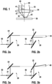
- Figure 1 shows the optical principle for adjusting an angle and a lateral offset of laser beams 51, 52, 53 with focusing optics 34.
- a first laser beam 51 strikes an optical axis 60 at a first distance 40 and a second laser beam 52 at a second distance 41 on the focusing optics 34.
- the two laser beams 51, 52 run in front of the focusing optics 34 parallel to the optical axis 60.
- a third laser beam 53 hits, based on the optical axis 60, at an angle to the focusing optics 34.
- the laser beams 51, 52, 53 are directed by the focusing optics 34 onto a workpiece 36 to be machined, with the two laser beams 51, 52 previously running parallel to the optical axis 60 being directed onto the optical axis Hit the workpiece, while the laser beam 53, which runs in front of the focusing optics 34 at an angle to the optical axis 60, hits the workpiece at a third distance 42 from the optical axis 60.
- the focusing optics 34 therefore converts a beam offset into an angle and an angle into a beam offset.
- the distance 40, 41 at which the laser beam 51, 52, 53 hits the focusing optics 34 can therefore be used to set the angle at which the laser beam 51, 52, 53 hits the workpiece 36.
- the distance 42 to the optical axis 60 at which the laser beam 51, 52, 53 hits the workpiece 36 can be specified by the angle at which the laser beam 51, 52, 53 hits the focusing optics 34.
- the angle of incidence and the paths in which a laser beam 51, 52, 53 is guided over the workpiece 36 can be specified. This makes it possible to direct the laser beam 51, 52, 53 quickly and along predetermined closed paths running around the optical axis 60 onto the workpiece 36 at suitable angles and to process it. This enables, for example, the drilling of holes or the circumferential welding of joining partners.
- Figure 2a shows a mirror arrangement 20 in the starting position with a first mirror 21 and a second mirror 22, from which a laser beam 50 is guided.
- the mirrors 21, 22 are designed as gimbal-suspended deflection mirrors, which can each be rotated via two tilting axes that are at least approximately orthogonal to one another.
- the drive takes place via piezo actuators.
- mirrors 21, 22 moved by linear drives can also be provided, or the function of a mirror 21, 22 can be realized by a pair of rotatably mounted mirrors with at least approximately orthogonal axes of rotation (galvanometer mirror).
- the mirrors 21, 22 enable the laser beam 50 to be deflected in the x and y directions, with the x direction in the illustration being perpendicular to the plane of the drawing and the y direction corresponding to the path of the beam between the mirrors 21, 22.
- the z-direction corresponds to the course of the laser beam 50 before and after the mirror arrangement 20.
- Figure 2b shows the mirror arrangement 20 with an offset laser beam 50.
- the two mirrors 21, 22 are rotated in the same direction and at the same angle about axes of rotation running in the x direction.
- the lateral offset 43 can be adjusted by selecting the tilt angle of the mirrors 21, 22.
- an offset 43 can be brought about in the x direction, so that the laser beam 50 can be offset to any xy coordinates within the limits given by the mirror arrangement 20.
- Figure 3a shows the mirror arrangement 20, as already in Figure 2a shown in the starting position of the mirrors 21, 22 as a comparison for the in Figure 3b shown course of the laser beam 50.
- Figure 3b shows the mirror arrangement 20 with a laser beam 50 emerging at an angle of attack 49.
- the second mirror 22 is rotated about an axis of rotation running in the x direction, while the first mirror 21 is in the starting position. In comparison to the direction of propagation when mirrors 21, 22 are arranged in parallel, this leads to a deflection of the laser beam 50 in the y direction. Accordingly, the laser beam can be deflected in the x direction by rotating the second mirror 22 about an axis of rotation running in the y direction.
- the angle of attack 49 of the laser beam can be adjusted as desired within the scope of the adjustment options of the mirror arrangement 20.
- both the lateral offset 43 and the angle of attack 49 of the laser beam 50 can be adjusted by the mirror arrangement 20.
- Figure 4 shows a schematic representation of a device for guiding a laser beam 50. The same identifiers already introduced are used.
- a mirror arrangement 20, an optical arrangement 13 for beam expansion and for variable adjustment of the focus distance of the laser beam 50 and focusing optics 34 are arranged along the optical axis 60.
- the mirror arrangement 20 corresponds to that in the Figures 2a, 2b, 3a, 3b arrangement shown.
- the laser beam 50 is laterally offset relative to the optical axis 60 by the mirror arrangement 20 and its direction of propagation is changed.
- the laser beam 50 follows a first trajectory 44 and, at a greater distance from the mirror arrangement 20, a second trajectory 45 with a correspondingly larger diameter.
- the optical structure can also be designed such that the diameter of the second trajectory 45 is smaller than or equal to the diameter of the first trajectory 44. If the diameters are identical, the wobble plane 61 and the focal plane match.
- a laser beam t1a 54.1 after the mirror arrangement 20 at a first time t1 a laser beam t2a 55.1 after the mirror arrangement 20 at a subsequent second time t2, and a laser beam t3a 56.1 after the mirror arrangement 20 are shown along the trajectories 44, 45 as an example third time t3 and a laser beam t4a 57.1 after the mirror arrangement 20 at a fourth time t4 during a movement of the laser beam 50 about the optical axis 60.
- the laser beam 50 moved in this way strikes an optical arrangement 13 for beam expansion and for variable adjustment of the focus distance of the laser beam 50.
- This optical arrangement 13 also known as a Z-translator, expands the incident laser radiation in such a way that the laser beam 50 is further away from the optical axis 60 is moved. Furthermore, the laser beam 50 can be easily adjusted to be convergent or divergent by the optical arrangement 13, whereby the in Figure 5 shown focal plane 62 or its distance from the wobble plane 61 can be moved. The optical arrangement 13 thus enables dynamic adjustment of the focal plane 62 according to the movement of the laser beam 50.
- the laser beam 50 follows a third trajectory 46 and in the further course of a fourth trajectory 47 shown path.
- These trajectories 46, 47 run on a larger diameter around the optical axis 60 compared to the second trajectory 45 due to the beam expansion.
- a laser beam t1b 54.2 is shown along the trajectories 46, 47 after the optical arrangement 13 at the first time t1, a laser beam t2b 55.2 after the optical arrangement 13 at the subsequent second time t2, a laser beam t3b 56.2 after the optical arrangement 13 at the third time t3 and a laser beam t4b 57.2 after the optical arrangement 13 at the fourth time t4 during a Movement of the laser beam 50 about the optical axis 60 is shown.
- the focusing optics 34 focuses the laser beam 50 in the focal plane 62. It converts the beam offset of the laser beam 50 into an angle and an angle in the propagation direction of the laser beam 50 to the optical axis 60 into a beam offset.
- the laser beam 50 crosses the optical axis 60 in the wobble plane 61 in order to then hit the workpiece in the focal plane 62, not shown.
- a laser beam t1c 54.3 after the focusing optics 34 at the first time t1 a laser beam t2c 55.3 after the focusing optics 34 at the subsequent second time t2
- a laser beam t4c 57.3 after the focusing optics 34 at the fourth time t4 during a movement of the laser beam 50 about the optical axis 60 for clarification, here too, by way of example, a laser beam t1c 54.3 after the focusing optics 34 at the first time t1, a laser beam t2c 55.3 after the focusing optics 34 at the subsequent second time t2, a laser beam t3c 56.3 after the focusing optics 34 at the third Time t3 and a laser beam t4c 57.3 after the focusing optics 34 at the fourth time t4 during a movement of the laser beam 50 about the optical axis 60.
- the optical arrangement 13 for beam expansion and for variable adjustment of the focus distance thus causes an offset multiplication, whereby even with a small adjustable lateral offset 43, a sufficiently large lateral offset can be set by the mirror arrangement 20 in front of the subsequent focusing optics 34 in order to ensure a sufficient adjustment range for to obtain the angle of incidence of the laser beam 50 on the workpiece 36.
- the beam offset and the angle of attack are both generated reflectively by the mirrors 21, 22 of the mirror arrangement 20. Since the angle of attack is also generated before the beam expansion, rotating mirrors are no longer necessary between the optical arrangement 13 for beam expansion and the focusing optics 34. This allows small and therefore dynamic mirrors 21, 22 to be used.
- the offset of the laser beam 50 to be generated by the mirror arrangement 20 is comparatively small due to the offset multiplication by the optical arrangement 34, so that no additional optical elements, such as folding mirrors, need to be provided in the mirror arrangement 20.
- commercially available and therefore inexpensive mirror arrangements 20, for example in the form of electroplated scanners with standard mirrors, can be used.
- the arrangement can be made compact thanks to the reflective beam guidance and the elimination of large scanning mirrors.
- Figure 5 shows in an exemplary embodiment an optical structure for guiding a laser beam 50 with a processing head 30, as used to generate an in Figure 4 the beam path shown is suitable.
- a laser source 10 a first beam splitter 12, the mirror arrangement 20, the optical arrangement 13 for beam expansion and for variable adjustment of the focus distance of the laser beam 50, a second beam splitter 33, the focusing optics 34 and a process gas nozzle 35 are arranged along the propagation of a laser beam 50 .
- First sensor elements 11 with associated additional technology are assigned to the first beam splitter 12.
- a camera 31 with additional technology and sensors as well as second sensor elements 32 with additional technology are assigned to the second beam splitter 33.
- the laser beam 50 is emitted by the laser source 10 and fed to the first beam splitter 12. Subsequently, the described lateral displacement and the adjustment of the angle of attack 49 of the laser beam 50 takes place in the mirror arrangement 20, shown by way of example by the laser beam t1a 54.1 after the mirror arrangement 20 at a first time t1 and the laser beam t2a 55.1 after the mirror arrangement 20 at a subsequent second time Time t2.
- the laser beam 50 is expanded with the described offset multiplication and the focus distance is set to a focal plane 62.
- the laser beam 50 is directed onto the focusing optics 34 by the second beam splitter 33.
- the focusing optics 34 converts the lateral offset of the laser beam 50 into an angle and the angle of attack 49 into a lateral offset.
- the optical system is designed in such a way that the laser beam 50, during its movement around the optical axis 60, intersects it in a wobble plane 61 and then in the focal plane 62 at a negative angle and laterally offset from the optical axis 60 onto the workpiece 36, not shown here meets.
- a process gas is supplied through the process gas nozzle 35, which prevents corrosion of the workpiece 36 during processing and blows away any removed material.
- the beam splitters 12, 33 are designed with appropriate coatings in such a way that a small part of the laser radiation as well as wavelengths adjacent to the laser wavelength are passed on to the sensor elements 11, 32 or to the camera 31.
- the first sensor elements 11 assigned to the first beam splitter 12 serve to monitor the beam profile and the beam position.
- the focal plane with the component to be processed can be analyzed.
- the spot size, focusing, the beam profile in focus, the processing result and the radiation of the plasma can be monitored.
- the second beam splitter 33 can be used to illuminate the workpiece coaxially.
- the second beam splitter 33, the camera 31, the second sensor elements 33, the focusing optics 34 and the process gas nozzle 35 are combined in the processing head 30. Since both the lateral offset and the setting of the angle of attack in the mirror arrangement 20 take place in front of the optical arrangement 13 for beam splitting, no movable mirrors need to be provided in the processing head 30, which, in addition to the advantages already described, enables a compact design of the processing head 30.
- Figure 6 shows an optical structure for guiding a laser beam 50 with several processing heads 30, 30.1, 30.2.
- the structure essentially corresponds to that in Figure 5 structure shown.
- a beam switch 14 is provided between the optical arrangement 13 for beam expansion and for variable adjustment of the focus distance of the laser beam 50 and the processing head 30. In the present exemplary embodiment, this divides the laser beam 50 between the processing head 30 and two further processing heads 30.1, 30.2. In alternative embodiments, the number of connected processing heads 30, 30.1, 30.2 can vary.
- the additional processing heads 30.1, 30.2 are constructed in accordance with the processing head 30, so that several workpieces 36 can be processed with one device.
- the beam switch 14 can be arranged between the mirror arrangement 20 and the optical arrangement 13 for beam expansion.
- the optical arrangement 13 for beam expansion and for variable adjustment of the focus distance of the laser beam 50 must then be provided several times in accordance with the number of processing heads 30, 30.1, 30.2.
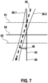
- Figure 7 shows the laser beam 50 in the area of the focal plane 62.
- the laser beam 50 is shown to show the focusing through the optical arrangement 13 for beam expansion and for variable adjustment of the focus distance and through the focusing optics 34 with its envelopes 58.1, 58.2.
- To illustrate the course of the laser beam 50 it is shown relative to an axis to represent the x-direction 64 and an axis to represent the z-direction 63, which runs on the optical axis 60 of the arrangement.
- the laser beam 50 intersects the optical axis 60 in the wobble plane 61 at the set exit angle 48.
- the focus of the laser beam 50 shown by the strongest constriction of the envelope 58.1, 58.2, lies in or near the focal plane 62, in which the processing of the not shown Workpiece 36 takes place.
- the laser beam 50 carries out a wobbling movement about the optical axis 60, whereby, for example, circular holes, but also holes that deviate from the round shape, can be drilled into a workpiece 36.
- the diameter of the hole is both determined by the angle of attack 49 at which the laser beam 50 hits the focusing optics 34, as well as by the positioning of the workpiece along the z-direction.
- the exit angle 48 results from the lateral offset in which the laser beam 50 hits the focusing optics 34.
- An adjustment of the focus distance by the optical arrangement 13 leads to a shift in the focal plane 62.
- the exit angle 48 is changed.
- a change in the angle of attack 49 after the mirror arrangement 20 leads to a displacement of the wobble plane 61 relative to the focal plane 62 and thus changes the diameter of the path in which the laser beam 50 moves on the focal plane 62.
- a slight change in the exit angle 48 takes place.
- software is provided in a control unit (not shown) of the mirror arrangement 20, which counteracts the influence of the exit angle 48 by a corresponding change in the beam offset.
Landscapes
- Physics & Mathematics (AREA)
- Optics & Photonics (AREA)
- Engineering & Computer Science (AREA)
- Plasma & Fusion (AREA)
- Mechanical Engineering (AREA)
- General Physics & Mathematics (AREA)
- Laser Beam Processing (AREA)
Description
- Die Erfindung betrifft eine Vorrichtung zur Führung eines Laserstrahls zur Bearbeitung eines Werkstücks mit einer Spiegelanordnung mit beweglichen Spiegeln zur Erzeugung eines Anstellwinkels des Laserstrahls auf eine fokussierende Optik zur Einstellung eines lateralen Versatzes des Laserstrahls auf dem Werkstück und zur Erzeugung eines lateralen Versatzes des Laserstrahls auf der fokussierenden Optik zur Einstellung eines Auftreffwinkels des Laserstrahls auf dem Werkstück.
- Die Erfindung betrifft weiterhin ein Verfahren zur Führung eines Laserstrahls zur Bearbeitung eines Werkstücks, wobei mit einer Spiegelanordnung mit beweglichen Spiegeln ein Anstellwinkel des Laserstrahls auf eine fokussierende Optik zur Einstellung eines lateralen Versatzes des Laserstrahls auf dem Werkstück und ein lateraler Versatz des Laserstrahls auf der fokussierenden Optik zur Einstellung eines Auftreffwinkels des Laserstrahls auf dem Werkstück erzeugt wird und wobei durch eine entsprechende Bewegung der Spiegel der Laserstrahl unter vorgegebenen Winkeln auf vorgegebenen, um eine optische Achse verlaufenden Bahnen über das Werkstück geführt wird.
- Eine solche Vorrichtung ist aus der
WO 2006/021442 bekannt. Die Schrift beschreibt einen Scankopf als Teil einer Laser Bohr- und Schneideinrichtung mit einer in den Lichtweg des Lasers angeordneten Reihe folgender Komponenten:
eine intensitätsregulierende Strahldämpfungseinheit in Verbindung mit einer eine parallele Strahlversetzung regulierenden Taumeleinheit, ein den Strahlquerschnitt des Lasers vergrößerndes Strahl-Expander-Teleskop, einen den Focus des Laserstrahls führenden Scanblock und eine den Laserstrahl auf die Probe fokussierende Arbeitseinheit sowie optional in den Lichtweg einkoppelbare zusätzliche Prüf- und Kontrolleinheiten. - Die Taumeleinheit ist aus zwei planparallelen, drehbaren Fenstern aufgebaut und ermöglicht einen seitlichen Versatz eines durchlaufenden Laserstrahls. Durch die Rotation der Fenster folgt der Laserstrahl einer geschlossenen Bahn um die optische Achse. Der seitliche Versatz und somit der Durchmesser der geschlossenen Bahn wird durch das Strahl-Expander-Teleskop vergrößert. Weiterhin kann durch das Strahl-Expander-Teleskop der Fokus des Laserstrahls in Ausbreitungsrichtung verschoben werden. Durch den Strahlversatz wird der Laserstrahl außerhalb der optischen Achse auf die fokussierende Arbeitseinheit gelenkt, so dass der Laserstrahl nach der Arbeitseinheit unter einem von dem eingestellten Versatz abhängigen Winkel auf das zu bearbeitende Werkstück trifft. Durch den nach dem Strahl-Expander-Teleskop angeordneten Scanblock wird der Laserstrahl mit einer Spiegelanordnung in eine X- beziehungsweise Y-Richtung abgelenkt. Der so unter einem Winkel auf die fokussierende Arbeitseinheit treffende Laserstrahl trifft entsprechend außerhalb der optischen Achse auf das Werkstück. Durch die Taumeleinheit und das nachfolgende Strahl-Expander-Teleskop wird demnach der Auftreffwinkel des Laserstrahls auf das Werkstück vorgegeben, während die Spiegelanordnung des Scanblocks den seitlichen Versatz des Laserstrahls auf dem Werkstück ermöglicht. Durch entsprechende Rotation der Fenster der Taumeleinheit und dynamischen Ablenkung des Laserstrahls durch den Scanblock wird der Laserstrahl unter vorgebbaren Winkeln auf einer in ihrem Verlauf durch den Scanblock vorgebbaren, geschlossenen Bahn um die optische Achse rotierend auf das Werkstück geleitet. Dies ermöglicht beispielsweise das Bohren von Löchern mit von der runden Form abweichenden Geometrien und negativer Konizität.
- Nachteilig bei entsprechend der
WO 2006/021442 aufgebauten Systemen ist der große benötige Scanspiegel in dem Scanblock, da der Strahl zuvor durch das Strahl-Expander-Teleskop bereits aufgeweitet und lateral versetzt wurde. Weiterhin benötigen die rotierenden Fenster der Taumeleinheit sehr große Scanwinkel beziehungsweise dicke Fenster mit hoher Trägheit, um den notwendigen Strahlversatz zu erzeugen. Beide Anforderungen führen zu einer deutlichen Einschränkung der Dynamik des Systems. Die Größe des Scanspiegels erfordert weiterhin einen Kompromiss zwischen dem maximalen Anstellwinkel und der erzielbaren Dynamik. Dadurch ist bei typischen Systemen der maximale Anstellwinkel auf ca. 5° beschränkt. Ein weiterer Nachteil der mit zwei rotierenden Fenstern aufgebauten Taumeleinheit liegt in einem durch Temperaturschwankungen hervorgerufenen Fokusshift. - Die Schrift
DE 10 2011 006 152 beschreibt eine Trepanieroptik zur Einstellung und Variation eines Propagationswinkels und einer lateralen Versetzung elektromagnetischer Strahlung, insbesondere eines Laserstrahls zur Anwendung in Bearbeitungssystemen. Die Trepanieroptik ist gekennzeichnet durch - eine eingangsseitige, aktuatorisch angetriebene Kippspiegelanordnung zur Reflektion der einfallenden elektromagnetischen Strahlung, und
- mindestens eine ausgangsseitige, aktuatorisch angetriebene Kippspiegelanordnung zur Weiterleitung der reflektierten elektromagnetischen Strahlung zur Ausgangsseite der Trepanieroptik,
- wobei die mindestens zwei Kippspiegelanordnungen mittels einer Steuerungseinrichtung jeweils um zwei orthogonale Kippachsen unabhängig voneinander derart verkippbar angetrieben sind, dass Propagationswinkel (ϕ) und laterale Versetzung (v) der elektromagnetischen Strahlung unabhängig voneinander variabel einstellbar sind. Die aktuatorisch angetriebenen Kippspiegelanordnungen können dabei durch Piezoaktuatoren oder Linearantriebe betätigt oder als Galvanometerspiegel ausgeführt sein. Der seitliche Versatz sowie der Winkel des Laserstrahls werden rein reflektiv vor einer Fokussiereinheit eingestellt. Durch die Fokussiereinheit wird der seitliche Versatz in einen Winkel und der Anstellwinkel in einen seitlichen Versatz umgewandelt und der Laserstrahl auf das zu bearbeitende Werkstück gelenkt. Die Kippspiegelanordnung ermöglicht durch ihre frei beweglichen Spiegel eine freie Vorgabe des Auftreffwinkels und der Bahn, auf welcher der Laserstrahl über das Werkstück gelenkt wird. Dabei ermöglicht die geringe Masse der Kippspiegel eine hohe Dynamik des Systems.
- Weitere Trepaniervorrichtungen sind aus der
US2011132881 A1 bekannt. - Um einen ausreichenden lateralen Versatz des Laserstrahls vor der Fokussiereinheit zur Erzeugung eines gewünschten Propagationswinkels nach der Fokussiereinheit zu erhalten ist jedoch eine aufwändige Optik in Form von präzise ausgerichteten Faltungsspiegeln innerhalb der Kippspiegelanordnung beziehungsweise ein langer, nicht kompakter Strahlengang notwendig.
- Es ist daher Aufgabe der Erfindung, eine vergleichsweise einfach aufgebaute optische Vorrichtung bereitzustellen, welche einen Laserstrahl mit einer hohen Dynamik unter einem gewünschten Winkel und auf in Grenzen frei wählbaren Bahnen auf ein zu bearbeitendes Werkstück lenkt. Es ist weiterhin Aufgabe der Erfindung, ein entsprechendes Verfahren bereitzustellen.
- Die Aufgabe der Erfindung wird durch eine Vorrichtung zur Führung eines Laserstrahls gemäß Anspruch 1, sowie durch ein entsprechendes Verfahren gemäß Anspruch 6, gelöst, wobei zwischen der Spiegelanordnung und der fokussierenden Optik eine optische Anordnung zur Strahlaufweitung und zur variablen Einstellung der Fokusentfernung des Laserstrahls angeordnet ist. Durch die Strahlaufweitung wird der seitliche Versatz des Laserstrahls, welcher von der Spiegelanordnung bewirkt wird, vergrößert. Der Laserstrahl kann somit in einem größeren Abstand von der optischen Achse auf die fokussierende Optik gelenkt werden, was zu einem größeren Einstellbereich des Auftreffwinkels auf das zu bearbeitende Werkstück führt. Auf zusätzliche Faltspiegel in der Spiegelanordnung kann somit verzichtet werden oder ihre Anzahl kann zumindest reduziert werden. Der Anstellwinkel wird vor der Aufweitung erzeugt, so dass keine drehenden Spiegel mehr zwischen der optischen Anordnung zur Strahlaufweitung und zur variablen Einstellung der Fokusentfernung und der fokussierenden Optik vorgesehen werden müssen. Dadurch können kleinere und damit dynamischere bewegliche Spiegel eingesetzt werden, was zu einer schnelleren Bewegung des Laserstrahls auf dem Werkstück führt. Durch die kleineren benötigen Spiegel und die anschließende Versatzmulitplikation durch die Strahlaufweitung wird es möglich, Spiegelanordnung zu verwenden, wie sie auch für andere Scan-Anwendungen in großer Stückzahl verwendet werden, so dass eine kostengünstige Herstellung der Vorrichtung ermöglicht wird.
- Durch die Möglichkeit, mit Hilfe der optischen Anordnung die Fokusentfernung des Laserstrahls einzustellen, kann diese unabhängig von dem Auftreffwinkel und dem lateralen Versatz auf die gewünschte Fokusebene auf dem Werkstück eingestellt werden. Der laterale Versatz und der Anstellwinkel des Laserstrahls können durch die Spiegelanordnung in alle Richtungen umlaufend zur optischen Achse dadurch eingestellt werden, dass die Spiegelanordnung aus zwei kardanisch gelagerten Spiegeln oder aus einem ersten Spiegelpaar mit parallelen Drehachsen und einem zweiten Spiegelpaar mit parallelen, zu dem ersten Spiegelpaar zumindest näherungsweise orthogonal angeordneten Drehachsen ausgeführt ist. Die Reihenfolge der Spiegel der beiden Spiegelpaare kann dabei beliebig vorgegeben sein. So können entlang der Ausbreitungsrichtung des Laserstrahls zunächst zwei um ihre x-Achse und anschließend zwei um ihre y-Achse drehbare Spiegel vorgesehen sein. Alternativ kann beispielsweise auch eine Reihenfolge der Spiegel mit den Drehachsen x-Achse, y-Achse, x-Achse, y-Achse oder jeder anderen Reihenfolge vorgesehen sein. Wesentlich für die Anordnung aus zwei Spiegelpaaren ist, dass sie aus zwei um ihre x-Achse drehbaren Spiegeln und zwei um ihre y-Achse drehbaren Spiegeln aufgebaut ist.
- Es kann vorgesehen sein, dass die Spiegel durch Piezoaktuatoren oder durch Linearantriebe angetrieben sind oder dass die Spiegel als Galvanometerspiegel ausgeführt sind.
- Die kardanisch gelagerten Spiegel können beispielsweise durch Piezoaktuatoren oder durch Linearantriebe in x- und y-Richtung gekippt werden und ermöglichen so eine entsprechende Ablenkung des Laserstrahls. Durch zwei solche in dem Strahlverlauf hintereinander geschaltete Spiegel können ein lateraler Versatz und ein Anstellwinkel des Laserstrahls in x- und y-Richtung eingestellt werden. Drehbar gelagerte Spiegelpaare können aus zumindest annähernd mit ihren Drehachsen senkrecht zueinander angeordneten Galvanometerspiegeln ausgeführt sein, wobei die Ablenkung in x-Richtung durch zwei Spiegel und die Ablenkung in y-Richtung durch zwei weitere Spiegel der beiden Spiegelpaare erfolgt. Durch zwei solche hintereinander geschalteten Spiegelpaare kann ebenfalls ein lateraler Versatz und ein Anstellwinkel des Laserstrahls in x- und y-Richtung eingestellt werden.
- Entsprechend einer bevorzugten Ausgestaltungsvariante der Erfindung kann es vorgesehen sein, dass in dem Strahlengang des Laserstrahls zwischen der Spiegelanordnung und der optischen Anordnung zur Strahlaufweitung und zur variablen Einstellung der Fokusentfernung eine Strahlweiche vorgesehen ist, welche den Laserstrahl auf zwei oder mehrere optische Anordnungen zur Strahlaufweitung und zur variablen Einstellung der Fokusentfernungen und den Strahlengängen folgend auf zwei oder mehrere fokussierende Optiken aufteilt oder dass in dem Strahlengang des Laserstrahls nach der optischen Anordnung zur Strahlaufweitung und zur variablen Einstellung der Fokusentfernung eine Strahlweiche vorgesehen ist, welche den Laserstrahl auf zwei oder mehrere fokussierende Optiken aufteilt. Der Laserstrahl kann somit aufgeteilt mehreren Bearbeitungsköpfen und darüber mehreren Werkstücken zugeführt werden.
- Ein vollständiger Aufbau der Vorrichtung kann dadurch realisiert werden, dass die Vorrichtung entlang der Ausbreitung des Laserstrahls zumindest folgende Komponenten aufweist:
- eine Laserquelle,
- die Spiegelanordnung
- die optische Anordnung zur Strahlaufweitung und zur variablen Einstellung der Fokusentfernung,
- die fokussierende Optik nach dem zweiten Strahlteiler.
- Die Laserquelle erzeugt den Laserstrahl. Dieser wird der bereits beschriebenen Spiegelanordnung und nachfolgend der Anordnung zur Strahlaufweitung und zur variablen Einstellung der Fokusentfernung zugeführt. Anschließend wird der Laserstrahl auf die fokussierende Optik und von dort in einer durch die Spiegelanordnung verursachten Taumelbewegung auf das Werkstück geleitet.
- Optional kann es vorgesehen sein, dass unmittelbar vor dem Werkstück eine Prozessgasdüse vorgesehen ist. Einer Gaszuführung beim Bohren durch eine solche koaxiale Prozessgasdüse ermöglicht erfahrungsgemäß bessere Bohrergebnisse, insbesondere bei hohen mittleren Laserleistungen. Die Gasströmung entfernt Abtragsprodukte aus der Wechselwirkungszone, andererseits können Oxidation oder auch die lonisationseffekte des Gases beeinflusst werden.
- Weiterhin kann es optional vorgesehen sein, dass in dem Strahlengang des Laserstrahls Strahlteiler vorgesehen sind, die eine Auskopplung von Laserlicht oder Anteilen des Laserlichts beziehungsweise Licht benachbarter Wellenlängen für Analysefunktionen ermöglichen. So kann zwischen der Laserquelle und der Spiegelanordnung ein erster Strahlteiler vorgesehen sein, der einen Teil des Laserstrahls einer Sensorik zur Überwachung beispielsweise des Strahlprofils und der Strahlposition zuführt. Ein zweiter Strahlteiler kann zwischen der optischen Anordnung zur Strahlaufweitung und zur variablen Einstellung der Fokusentfernung und der fokussierenden Optik vorgesehen sein. Nach dem zweiten Strahlteiler können beispielsweise die Brennebene mit dem zu bearbeitenden Bauteil analysiert werden. Es können die Spotgröße, die Fokussierung, das Strahlprofil im Fokus, das Bearbeitungsergebnis sowie die Abstrahlung des Plasmas überwacht werden. Weiterhin kann durch den zweiten Strahlteiler eine koaxiale Beleuchtung erfolgen.
- Zusätzlich zu den aufgeführten Komponenten kann die zuvor beschriebene Strahlweiche in den Strahlengang eingeführt sein, so dass der Laserstrahl entsprechend mehreren analog aufgebauten Bearbeitungsköpfen zugeführt werden kann.
- Die das Verfahren betreffende Aufgabe der Erfindung wird dadurch gelöst, dass der Verlauf des Laserstrahls mit einer zwischen der Spiegelanordnung und der fokussierenden Optik vorgesehenen optischen Anordnung aufgeweitet wird und dass die Fokusentfernung des Laserstrahls durch die optische Anordnung eingestellt wird. Durch die Aufweitung wird ein durch die Spiegelanordnung erzeugter Versatz des Laserstrahls verstärkt, so dass der Laserstrahl weiter entfernt von der optischen Achse auf die fokussierende Optik trifft und demnach unter einem größeren Winkel auf das Werkstück gelenkt werden kann. Durch den mit der Spiegelanordnung erzeugten Anstellwinkel und den durch die optische Anordnung verstärkten lateralen Versatz des Laserstrahls kann bei entsprechender Bewegung der Spiegel der Laserstrahl in um die optische Achse verlaufenden Bahnen und unter einem vorgegebenen, zur optischen Achse hin ausgerichteten Winkel auf das Werkstück gelenkt werden. Der Laserstrahl führt somit nach der fokussierenden Optik eine vorgegebene Taumelbewegung um die optische Achse durch, womit beispielsweise Bohrungen mit von der runden Form abweichenden Geometrien, Hinterschnitte oder Mikro-Durchbrüche erzeugt werden können. Durch die Einstellung der Fokusentfernung wird der Laserstrahl dabei immer in der gewünschten Fokusebene fokussiert.
- Wird die Fokusentfernung durch die optische Anordnung verstellt, so ändert sich neben der Fokusebene auch geringfügig und unbeabsichtigt der Austrittswinkel des Laserstrahls aus der fokussierenden Optik und damit der Auftreffwinkel des Laserstrahls auf dem Werkstück. Der Austrittswinkel aus der fokussierenden Optik wird weiterhin geringfügig bei einer Änderung des Anstellwinkels durch die Spiegelanordnung beeinflusst. Um dies wieder auszugleichen und den gewünschten Austrittswinkel aus der fokussierenden Optik und somit den gewünschten Auftreffwinkel auf dem Werkstück beizubehalten ist es, gemäß der Erfindung, vorgesehen, dass eine durch eine Veränderung der Fokusentfernung durch die optische Anordnung oder eine Veränderung des Anstellwinkels durch die Spiegelanordnung verursachte Veränderung des Auftreffwinkels des Laserstrahls auf dem Werkstück durch eine Veränderung des lateralen Versatzes des Laserstrahls auf der fokussierenden Optik ausgeglichen wird. Der Ausgleich wird durch eine entsprechende Software in der Ansteuerelektronik der Spiegelanordnung gesteuert
- Die Erfindung wird im Folgenden anhand eines in den Figuren dargestellten Ausführungsbeispiels näher erläutert. Es zeigen:
-
Figur 1 das optische Prinzip zur Einstellung eines Winkels und eines lateralen Versatzes von Laserstrahlen mit einer fokussierenden Optik, -
Figur 2a eine Spiegelanordnung in Ausgangsposition, -
Figur 2b die Spiegelanordnung mit versetztem Laserstrahl, -
Figur 3a die Spiegelanordnung in Ausgangsposition, -
Figur 3b die Spiegelanordnung mit einem unter einem Anstellwinkel austretenden Laserstrahl, -
Figur 4 in schematischer Darstellung eine Vorrichtung zur Führung eines Laserstrahls, -
Figur 5 einen optischen Aufbau zur Führung eines Laserstrahls mit einem Bearbeitungskopf, -
Figur 6 einen optischen Aufbau zur Führung eines Laserstrahls mit mehreren Bearbeitungsköpfen, -
Figur 7 einen Laserstrahl im Bereich der Fokusebene. -
Figur 1 zeigt das optische Prinzip zur Einstellung eines Winkels und eines lateralen Versatzes von Laserstrahlen 51, 52, 53 mit einer fokussierenden Optik 34. Ein erster Laserstrahl 51 trifft in einem ersten Abstand 40 und ein zweiter Laserstrahl 52 in einem zweiten Abstand 41 zu einer optischen Achse 60 auf die fokussierende Optik 34. Die beiden Laserstrahlen 51, 52 verlaufen vor der fokussierenden Optik 34 parallel zu der optischen Achse 60. Ein dritter Laserstrahl 53 trifft, bezogen auf die optische Achse 60, unter einem Winkel auf die fokussierende Optik 34. Die Laserstrahlen 51, 52, 53 werden durch die fokussierende Optik 34 auf ein zu bearbeitendes Werkstück 36 gelenkt, wobei die beiden zuvor parallel zur optischen Achse 60 verlaufenden Laserstrahlen 51, 52 auf der optischen Achse auf das Werkstück treffen, während der vor der fokussierenden Optik 34 in einem Winkel zur optischen Achse 60 verlaufende Laserstrahl 53 in einem dritten Abstand 42 von der optischen Achse 60 auf das Werkstück trifft. - Die fokussierende Optik 34 wandelt demnach einen Strahlversatz in einen Winkel und einen Winkel in einen Strahlversatz um. Je weiter beabstandet der Laserstrahl 51, 52, 53 auf die fokussierende Optik 34 trifft, desto stärker wird er durch die fokussierende Optik 34 zur optischen Achse 60 hin gebrochen. Durch den Abstand 40, 41, in dem der Laserstrahl 51, 52, 53 auf die fokussierende Optik 34 trifft, kann demnach der Winkel eingestellt werden, in dem der Laserstrahl 51, 52, 53 auf das Werkstück 36 trifft.
- Durch den Winkel, mit dem der Laserstrahl 51, 52, 53 auf die fokussierende Optik 34 trifft, kann der Abstand 42 zur optischen Achse 60 vorgegeben werden, in dem der Laserstrahl 51, 52, 53 auf das Werkstück 36 trifft. Durch entsprechend Führung des Laserstrahls 51, 52, 53 über die fokussierende Optik 34 können demnach die Auftreffwinkel und die Bahnen, in denen ein Laserstrahl 51, 52, 53 über das Werkstück 36 geführt wird, vorgegeben werden. Dadurch wird es möglich, den Laserstrahl 51, 52, 53 schnell und entlang vorgegebener, um die optische Achse 60 verlaufender geschlossener Bahnen unter geeigneten Winkeln auf das Werkstück 36 zu lenken und dieses zu bearbeiten. Dies ermöglicht beispielsweise das Bohren von Löchern oder das umlaufende Verschweißen von Fügepartnern.
-
Figur 2a zeigt eine Spiegelanordnung 20 in Ausgangsposition mit einem ersten Spiegel 21 und einem zweiten Spiegel 22, von denen ein Laserstrahl 50 geführt ist. Die Spiegel 21, 22 sind in dem Ausführungsbeispiel als kardanisch aufgehängter Ablenkspiegel ausgeführt, welche jeweils über zwei zumindest annähernd orthogonal zueinander stehende Kippachsen gedreht werden können. Der Antrieb erfolgt dabei über Piezoaktuatoren. Alternativ dazu können auch durch Linearantriebe bewegte Spiegel 21, 22 vorgesehen sein oder die Funktion eines Spiegels 21, 22 kann durch ein Paar drehbar gelagerter Spiegel mit zumindest näherungsweise orthogonalen Drehachsen (Galvanometerspiegel) realisiert sein. - Die Spiegel 21, 22 ermöglichen die Ablenkung des Laserstrahls 50 in x- und y-Richtung, wobei in der Darstellung die x-Richtung senkrecht zur Zeichenebene und die y-Richtung entsprechend dem Strahlverlauf zwischen den Spiegeln 21, 22 verläuft. Die z-Richtung entspricht dem Verlauf des Laserstrahls 50 vor und nach der Spiegelanordnung 20.
-
Figur 2b zeigt die Spiegelanordnung 20 mit versetztem Laserstrahl 50. Im Vergleich zuFigur 2a sind die beiden Spiegel 21, 22 gleichsinnig und um einen gleichen Winkel um in x-Richtung verlaufende Drehachsen verdreht. Dadurch bildet sich gegenüber dem Verlauf des Laserstrahls 50 in Ausgangsposition der Spiegel 21, 22 ein lateraler Versatz 43 des Laserstrahls 40 in y-Richtung aus. Durch die Wahl des Kippwinkels der Spiegel 21, 22 kann der laterale Versatz 43 eingestellt werden. Durch eine entsprechend Drehung der Spiegel 21, 22 um in y-Richtung verlaufende Drehachsen kann ein Versatz 43 in x-Richtung bewirkt werden, so dass der Laserstrahl 50 in den durch die Spiegelanordnung 20 gegebenen Grenzen auf beliebige x-y-Koordinaten versetzt werden kann. -
Figur 3a zeigt die Spiegelanordnung 20, wie bereits inFigur 2a gezeigt, in Ausgangsposition der Spiegel 21, 22 als Vergleich für den inFigur 3b gezeigten Verlauf des Laserstrahls 50. -
Figur 3b zeigt die Spiegelanordnung 20 mit einem unter einem Anstellwinkel 49 austretenden Laserstrahl 50. Um diesen Anstellwinkel 49 zu erhalten ist der zweite Spiegel 22 um eine in x-Richtung verlaufende Drehachse verdreht, während der erste Spiegel 21 in der Ausgangsposition steht. Dies führt im Vergleich zur Ausbreitungsrichtung bei parallel angeordneten Spiegel 21, 22 zu einer Ablenkung des Laserstrahls 50 in y-Richtung. Entsprechend kann der Laserstrahl durch eine Drehung des zweiten Spiegels 22 um eine in y-Richtung verlaufende Drehachse in x-Richtung abgelenkt werden. Durch die Spiegelanordnung 20 kann somit der Anstellwinkel 49 des Laserstrahls im Rahmen der Einstellmöglichkeiten der Spiegelanordnung 20 beliebig eingestellt werden. Durch Überlagerung der in denFiguren 2b und 3b gezeigten Spiegelbewegungen kann sowohl der laterale Versatz 43 wie auch der Anstellwinkel 49 des Laserstrahls 50 durch die Spiegelanordnung 20 eingestellt werden. -
Figur 4 zeigt in schematischer Darstellung eine Vorrichtung zur Führung eines Laserstrahls 50. Dabei sind die gleichen bereits eingeführten Bezeichner verwendet. - Entlang der optischen Achse 60 sind eine Spiegelanordnung 20, eine optische Anordnung 13 zur Strahlaufweitung und zur variablen Einstellung der Fokusentfernung des Laserstrahls 50 und eine fokussierende Optik 34 angeordnet. Die Spiegelanordnung 20 entspricht dabei der in den
Figuren 2a, 2b, 3a, 3b gezeigten Anordnung. - Der Laserstrahl 50 wird durch die Spiegelanordnung 20 gegenüber der optischen Achse 60 lateral versetzt und seine Ausbreitungsrichtung wird geändert. Durch eine entsprechende Ansteuerung der Spiegel 21, 22 der Spiegelanordnung folgt der Laserstrahl 50 einer ersten Trajektorie 44 und in einem größeren Abstand von der Spiegelanordnung 20 einer zweiten Trajektorie 45 mit entsprechend größerem Durchmesser. Alternativ kann der optische Aufbau auch so ausgeführt sein, dass der Durchmesser der zweiten Trajektorie 45 kleiner als der Durchmesser der ersten Trajektorie 44 oder gleich ist. Sind die Durchmesser identisch, stimmen die Taumelebene 61 und Brennebene überein. Zur Verdeutlichung sind beispielhaft entlang den Trajektorien 44, 45 ein Laserstrahl t1a 54.1 nach der Spiegelanordnung 20 zu einem ersten Zeitpunkt t1, ein Laserstrahl t2a 55.1 nach der Spiegelanordnung 20 zu einem darauf folgenden zweiten Zeitpunkt t2, ein Laserstrahl t3a 56.1 nach der Spiegelanordnung 20 zu einem dritten Zeitpunkt t3 und ein Laserstrahl t4a 57.1 nach der Spiegelanordnung 20 zu einem vierten Zeitpunkt t4 während einer Bewegung des Laserstrahls 50 um die optische Achse 60 eingezeichnet. Der so bewegte Laserstrahl 50 trifft erfindungsgemäß auf eine optische Anordnung 13 zur Strahlaufweitung und zur variablen Einstellung der Fokusentfernung des Laserstrahls 50. Durch diese auch Z-Translator genannte optische Anordnung 13 wird die auftreffende Laserstrahlung derart aufgeweitet, dass der Laserstrahl 50 weiter von der optischen Achse 60 versetzt wird. Weiterhin kann der Laserstrahl 50 durch die optische Anordnung 13 leicht konvergent oder divergent eingestellt werden, wodurch die in
Figur 5 gezeigte Fokusebene 62 beziehungsweise deren Abstand zur Taumelebene 61 verschoben werden kann. Die optische Anordnung 13 ermöglicht so eine dynamische Anpassung der Fokusebene 62 entsprechend der Bewegung des Laserstrahls 50. - Nach der optischen Anordnung 13 zur Strahlaufweitung und zur variablen Einstellung der Fokusentfernung folgt der Laserstrahl 50 einer durch eine dritten Trajektorie 46 und im weiteren Verlauf einer vierten Trajektorie 47 gezeigten Bahn. Diese Trajektorien 46, 47 laufen gegenüber der zweiten Trajektorie 45 auf Grund der Strahlaufweitung auf einem größeren Durchmesser um die optische Achse 60. Zur Verdeutlichung dieser Versatzmultiplikation sind beispielhaft entlang den Trajektorien 46, 47 ein Laserstrahl t1b 54.2 nach der optischen Anordnung 13 zu dem ersten Zeitpunkt t1, ein Laserstrahl t2b 55.2 nach der optischen Anordnung 13 zu dem darauf folgenden zweiten Zeitpunkt t2, ein Laserstrahl t3b 56.2 nach der optischen Anordnung 13 zu dem dritten Zeitpunkt t3 und ein Laserstrahl t4b 57.2 nach der optischen Anordnung 13 zu dem vierten Zeitpunkt t4 während einer Bewegung des Laserstrahls 50 um die optische Achse 60 eingezeichnet.
- Die fokussierende Optik 34 fokussiert den Laserstrahl 50 in der Fokusebene 62. Sie wandelt den Strahlversatz des Laserstrahls 50 in einen Winkel und einen Winkel in der Ausbreitungsrichtung des Laserstrahls 50 zur optischen Achse 60 in einen Strahlversatz um. Dabei kreuzt der Laserstrahl 50 die optische Achse 60 in der Taumelebene 61, um anschließend nicht dargestellt in der Fokusebene 62 auf das Werkstück zu treffen. Zur Verdeutlichung sind auch hier beispielhaft ein Laserstrahl t1c 54.3 nach der fokussierenden Optik 34 zu dem ersten Zeitpunkt t1, ein Laserstrahl t2c 55.3 nach der fokussierenden Optik 34 zu dem darauf folgenden zweiten Zeitpunkt t2, ein Laserstrahl t3c 56.3 nach der fokussierenden Optik 34 zu dem dritten Zeitpunkt t3 und ein Laserstrahl t4c 57.3 nach der fokussierenden Optik 34 zu dem vierten Zeitpunkt t4 während einer Bewegung des Laserstrahls 50 um die optische Achse 60 eingezeichnet.
- Die optische Anordnung 13 zur Strahlaufweitung und zur variablen Einstellung der Fokusentfernung bewirkt somit eine Versatzmultiplikation, wodurch sich auch bei geringem einstellbaren seitlichen Versatz 43 durch die Spiegelanordnung 20 ein ausreichend großer seitlicher Versatz vor der nachfolgenden fokussierenden Optik 34 einstellen lässt, um so einen ausreichenden Stellbereich für den Auftreffwinkel des Laserstrahls 50 auf dem Werkstück 36 zu erhalten.
- Der Strahlversatz und der Anstellwinkel werden beide durch die Spiegel 21, 22 der Spiegelanordnung 20 reflektiv erzeugt. Da auch der Anstellwinkel vor der Strahlaufweitung erzeugt wird sind keine drehenden Spiegel mehr zwischen der optischen Anordnung 13 zur Strahlaufweitung und der fokussierenden Optik 34 notwendig. Dadurch können kleine und damit dynamische Spiegel 21, 22 verwendet werden. Der durch die Spiegelanordnung 20 zu erzeugende Versatz des Laserstrahls 50 ist auf Grund der Versatzmultiplikation durch die optische Anordnung 34 vergleichsweise klein, so dass keine zusätzlichen optischen Elemente, wie beispielsweise Faltspiegel, in der Spiegelanordnung 20 vorgesehen werden müssen. Dies führt dazu, dass handelsübliche und damit günstige Spiegelanordnungen 20, beispielsweise in Form von Galvano-Scannern mit Standard-Spiegeln, verwendet werden können. Die Anordnung kann durch die reflektive Strahlführung und durch den Wegfall großer Scanspiegel kompakt aufgebaut werden.
- In einer alternativen Ausführungsform kann es vorgesehen sein, dass größere optische Abstände durch entsprechende Faltspiegel gefaltet werden. Dadurch kann ein noch kompakterer Aufbau erreicht werden. Die Anzahl der benötigten Faltspiegel ist im Vergleich zu bekannten Systemen gering.
-
Figur 5 zeigt in einem Ausführungsbeispiel einen optischen Aufbau zur Führung eines Laserstrahls 50 mit einem Bearbeitungskopf 30, wie er zur Erzeugung eines inFigur 4 gezeigten Strahlengangs geeignet ist. - Entlang der Ausbreitung eines Laserstrahls 50 sind eine Laserquelle 10, ein erster Strahlteiler 12, die Spiegelanordnung 20, die optische Anordnung 13 zur Strahlaufweitung und zur variablen Einstellung der Fokusentfernung des Laserstrahls 50, ein zweiter Strahlteiler 33, die fokussierende Optik 34 und einer Prozessgasdüse 35 angeordnet. Dem ersten Strahlteiler 12 sind erste Sensorelemente 11 mit zugehöriger Zusatztechnik zugeordnet. Dem zweiten Strahlteiler 33 sind einer Kamera 31 mit Zusatztechnik und Sensorik sowie zweite Sensorelemente 32 mit Zusatztechnik zugeordnet.
- Der Laserstrahl 50 wird von der Laserquelle 10 ausgesendet dem ersten Strahlteiler 12 zugeführt. Anschließend erfolgt in der Spiegelanordnung 20 die beschriebene laterale Versetzung sowie die Einstellung des Anstellwinkels 49 des Laserstrahls 50, beispielhaft gezeigt durch den Laserstrahl t1a 54.1 nach der Spiegelanordnung 20 zu einem ersten Zeitpunkt t1 und den Laserstrahl t2a 55.1 nach der Spiegelanordnung 20 zu einem darauf folgenden zweiten Zeitpunkt t2. Durch die optische Anordnung 13 zur Strahlaufweitung und zur variablen Einstellung der Fokusentfernung des Laserstrahls 50 wird der Laserstrahl 50 mit der beschriebenen Versatzmultiplikation aufgeweitet und die Fokusentfernung wird auf eine Fokusebene 62 eingestellt. Wiederum beispielhaft durch einen Laserstrahl t1b 54.2 nach der optischen Anordnung 13 zu dem ersten Zeitpunkt t1 und einen Laserstrahl t2b 55.2 nach der optischen Anordnung 13 zu dem zweiten Zeitpunkt t2 dargestellt wird der Laserstrahl 50 durch den zweiten Strahlteiler 33 auf die fokussierende Optik 34 gelenkt. Die fokussierende Optik 34 wandelt den seitlichen Versatz des Laserstrahls 50 in einen Winkel und den Anstellwinkel 49 in einen seitlichen Versatz um. Das optische System ist dabei so ausgelegt, dass der Laserstrahl 50 während seiner Bewegung um die optische Achse 60 diese in einer Taumelebene 61 schneidet und dann in der Fokusebene 62 unter einem negativen Winkel und seitlich versetzt zur optischen Achse 60 auf das hier nicht dargestellte Werkstück 36 trifft. Durch die Prozessgasdüse 35 wird ein Prozessgas zugeführt, welches eine Korrosion des Werkstücks 36 während der Bearbeitung verhindert und abgetragenes Material wegbläst.
- Die Strahlteiler 12, 33 sind durch entsprechende Beschichtungen so ausgeführt, dass ein geringer Teil der Laserstrahlung sowie zur Laserwellenlänge benachbarte Wellenlängen zu den Sensorelementen 11, 32 beziehungsweise zur Kamera 31 weiter geleitet werden.
- Die dem ersten Strahlteiler 12 zugeordneten ersten Sensorelemente 11 dienen in dem Ausführungsbeispiel der Überwachung des Strahlprofils und der Strahlposition. Mit der dem zweiten Strahlteiler 33 folgenden zweite Sensorik 32 und der Kamera 31 können die Brennebene mit dem zu bearbeitenden Bauteil analysiert werden. Es können die Spotgröße, die Fokussierung, das Strahlprofil im Fokus, das Bearbeitungsergebnis sowie die Abstrahlung des Plasmas überwacht werden. Weiterhin kann durch den zweiten Strahlteiler 33 eine koaxiale Beleuchtung des Werkstücks erfolgen.
- Der zweite Strahlteiler 33, die Kamera 31, die zweiten Sensorelemente 33, die fokussierende Optik 34 und die Prozessgasdüse 35 sind in dem Bearbeitungskopfes 30 zusammengefasst. Da sowohl der seitliche Versatz wie auch die Einstellung des Anstellwinkels in der Spiegelanordnung 20 vor der optischen Anordnung 13 zur Strahlaufteilung erfolgt, müssen in dem Bearbeitungskopf 30 keine beweglichen Spiegel vorgesehen sein, was neben den bereits beschriebenen Vorteilen einen kompakten Aufbau des Bearbeitungskopfes 30 ermöglicht.
-
Figur 6 zeigt einen optischen Aufbau zur Führung eines Laserstrahls 50 mit mehreren Bearbeitungsköpfen 30, 30.1, 30.2. Der Aufbau entspricht dabei im Wesentlichen dem inFigur 5 gezeigten Aufbau. Zusätzlich ist zwischen der optischen Anordnung 13 zur Strahlaufweitung und zur variablen Einstellung der Fokusentfernung des Laserstrahls 50 und dem Bearbeitungskopf 30 eine Strahlweiche 14 vorgesehen. Diese teilt den Laserstrahl 50 in dem vorliegenden Ausführungsbeispiel auf den Bearbeitungskopf 30 und zwei weitere Bearbeitungsköpfe 30.1, 30.2 auf. In alternativen Ausführungsformen kann die Anzahl der angeschlossenen Bearbeitungsköpfe 30, 30.1, 30.2 variieren. Die zusätzlichen Bearbeitungsköpfe 30.1, 30.2 sind entsprechend dem Bearbeitungskopf 30 aufgebaut, so dass mit einer Vorrichtung mehrere Werkstücke 36 bearbeitet werden können. - In einer alternativen Ausführungsvariante kann die Strahlweiche 14 zwischen der Spiegelanordnung 20 und der optischen Anordnung 13 zur Strahlaufweitung angeordnet sein. Die optische Anordnung 13 zur Strahlaufweitung und zur variablen Einstellung der Fokusentfernung des Laserstrahls 50 muss dann entsprechend der Anzahl der Bearbeitungsköpfe 30, 30.1, 30.2 mehrfach vorgesehen sein.
-
Figur 7 zeigt den Laserstrahl 50 im Bereich der Fokusebene 62. Der Laserstrahl 50 ist dabei zur Darstellung der Fokussierung durch die optische Anordnung 13 zur Strahlaufweitung und zur variablen Einstellung der Fokusentfernung und durch die fokussierende Optik 34 mit seinen Einhüllenden 58.1, 58.2 gezeigt. Zur Darstellung des Verlaufs des Laserstrahls 50 ist dieser gegenüber einer Achse zur Darstellung der x-Richtung 64 und einer Achse zur Darstellung der z-Richtung 63, welche auf der optischen Achse 60 der Anordnung verläuft, gezeigt. Der Laserstrahl 50 schneidet die optische Achse 60 in der Taumelebene 61 unter dem eingestellten Austrittswinkel 48. Der Fokus des Laserstrahls 50 liegt, dargestellt durch die stärkste Einschnürung der Einhüllenden 58.1, 58.2, in oder nahe der Fokusebene 62, in der die Bearbeitung des nicht dargestellten Werkstücks 36 erfolgt. - Durch die Einstellung der Spiegel 21, 22 der Spiegelanordnung 20 führt der Laserstrahl 50 eine Taumelbewegung um die optische Achse 60 aus, wodurch beispielsweise kreisrunde Löcher, aber auch von der runden Form abweichende Löcher in ein Werkstück 36 gebohrt werden können. Der Durchmesser der Bohrung wird dabei sowohl durch den Anstellwinkel 49, in dem der Laserstrahl 50 auf die fokussierende Optik 34 trifft, als auch durch die Positionierung des Werkstücks entlang der z-Richtung, vorgegeben. Der Austrittswinkel 48 ergibt sich aus dem seitlichen Versatz, in dem der Laserstrahl 50 auf die fokussierende Optik 34 trifft.
- Eine Verstellung der Fokusentfernung durch die optische Anordnung 13 führt zu einer Verschiebung der Fokusebene 62. Durch eine Änderung des Strahlversatzes durch die Spiegelanordnung 20 wird der Austrittswinkel 48 verändert. Eine Änderung des Anstellwinkels 49 nach der Spiegelanordnung 20 führt zu einer Verschiebung der Taumelebene 61 gegenüber der Fokusebene 62 und ändert damit den Durchmesser der Bahn, in welcher sich der Laserstrahl 50 auf der Fokusebene 62 bewegt. Dabei erfolgt auch hier eine leichte Veränderung des Austrittswinkels 48. Um diese unbeabsichtigten Änderungen des Austrittswinkels 48 zu kompensieren ist in einer nicht dargestellten Steuereinheit der Spiegelanordnung 20 eine Software vorgesehen, welche durch eine entsprechende Änderung des Strahlversatzes der Beeinflussung des Austrittswinkels 48 entgegen wirkt.
Claims (6)
- Vorrichtung zur Führung eines Laserstrahls (50) zur Bearbeitung eines Werkstücks (36) mit einer Spiegelanordnung (20) mit beweglichen Spiegeln (21, 22) zur Erzeugung eines Anstellwinkels (49) des Laserstrahls (50) auf eine entlang der Ausbreitungsrichtung desselben angeordnete fokussierende Optik (34) zur Einstellung eines lateralen Versatzes des Laserstrahls (50) auf dem Werkstücks (36) und zur Erzeugung eines lateralen Versatzes (43) des Laserstrahls (50) auf der fokussierenden Optik (34) zur Einstellung eines Auftreffwinkels des Laserstrahls (50) auf dem Werkstück (36), dadurch gekennzeichnet, dass zwischen der Spiegelanordnung (20) und der fokussierenden Optik (34) eine optische Anordnung (13) zur Strahlaufweitung und zur variablen Einstellung der Fokusentfernung des Laserstrahls (50) angeordnet ist, wobei eine Software in der Ansteuerelektronik der Spiegelanordnung (20) dazu eingerichtet ist, eine durch eine Veränderung der Fokusentfernung durch die optische Anordnung (13) oder durch eine Veränderung des Anstellwinkels (49) durch die Spiegelanordnung (20) verursachte Veränderung des Auftreffwinkels des Laserstrahls (50) auf dem Werkstück durch eine Veränderung des lateralen Versatzes des Laserstrahls (50) auf der fokussierenden Optik auszugleichen.
- Vorrichtung nach Anspruch 1, dadurch gekennzeichnet, dass die Spiegelanordnung (20) aus zwei kardanisch gelagerten Spiegeln (21, 22) oder aus einem ersten Spiegelpaar mit parallelen Drehachsen und einem zweiten Spiegelpaar mit parallelen, zu dem ersten Spiegelpaar zumindest näherungsweise orthogonal angeordneten Drehachsen ausgeführt ist.
- Vorrichtung nach Anspruch 1 oder 2, dadurch gekennzeichnet, dass die Spiegel (21, 22) durch Piezoaktoren oder durch Linearantriebe angetrieben sind oder dass die Spiegel (21, 22) als Galvanometerspiegel ausgeführt sind.
- Vorrichtung nach einem der Ansprüche 1 bis 3, dadurch gekennzeichnet, dass in dem Strahlengang des Laserstrahls (50) zwischen der Spiegelanordnung (20) und der optischen Anordnung zur Strahlaufweitung und zur variablen Einstellung der Fokusentfernung eine Strahlweiche vorgesehen ist, welche den Laserstrahl (50) auf zwei oder mehrere optische Anordnungen zur Strahlaufweitung und zur variablen Einstellung der Fokusentfernungen und den Strahlengängen folgend auf zwei oder mehrere fokussierende Optiken (34) aufteilt oder dass in dem Strahlengang des Laserstrahls (50) nach der optischen Anordnung (13) zur Strahlaufweitung und zur variablen Einstellung der Fokusentfernung eine Strahlweiche (14) vorgesehen ist, welche den Laserstrahl (50) auf zwei oder mehrere fokussierende Optiken (34) aufteilt.
- Vorrichtung nach einem der Ansprüche 1 bis 4, dadurch gekennzeichnet, dass die Vorrichtung entlang der Ausbreitung des Laserstrahls (50) zumindest folgende Komponenten aufweist:∘ eine Laserquelle (10)∘ die Spiegelanordnung (20)∘ die optische Anordnung (13) zur Strahlaufweitung und zur variablen Einstellung der Fokusentfernung∘ die fokussierende Optik (34) nach einem Strahlteiler (33).
- Verfahren zur Führung eines Laserstrahls (50) zur Bearbeitung eines Werkstücks (36), wobei mit einer Spiegelanordnung (20) mit beweglichen Spiegeln (21, 22) ein Anstellwinkel (49) des Laserstrahls (50) auf eine fokussierende Optik (34) zur Einstellung eines lateralen Versatzes des Laserstrahls (50) auf dem Werkstücks (36) und ein lateraler Versatz (43) des Laserstrahls (50) auf der fokussierenden Optik (34) zur Einstellung eines Auftreffwinkels des Laserstrahls (50) auf dem Werkstücks (36) erzeugt wird und wobei durch eine entsprechende Bewegung der Spiegel (21, 22) der Laserstrahl (50) unter vorgegebenen Winkeln auf vorgegebenen, um eine optische Achse verlaufenden Bahnen über das Werkstücks (36) geführt wird, dadurch gekennzeichnet, dass der Verlauf des Laserstrahls (50) mit einer zwischen der Spiegelanordnung (20) und der fokussierenden Optik (34) vorgesehenen optischen Anordnung (13) aufgeweitet wird und dass die Fokusentfernung des Laserstrahls (50) durch die optische Anordnung (13) eingestellt wird, wobei eine durch eine Veränderung der Fokusentfernung durch die optische Anordnung (13) oder durch eine Veränderung des Anstellwinkels (49) durch die Spiegelanordnung (20) verursachte Veränderung des Auftreffwinkels des Laserstrahls (50) auf dem Werkstück durch eine Veränderung des lateralen Versatzes des Laserstrahls (50) auf der fokussierenden Optik ausgeglichen wird.
Applications Claiming Priority (2)
| Application Number | Priority Date | Filing Date | Title |
|---|---|---|---|
| DE201310222834 DE102013222834A1 (de) | 2013-11-11 | 2013-11-11 | Vorrichtung und Verfahren zur Führung eines Laserstrahls |
| PCT/EP2014/070751 WO2015067411A1 (de) | 2013-11-11 | 2014-09-29 | Vorrichtung und verfahren zur führung eines laserstrahls |
Publications (2)
| Publication Number | Publication Date |
|---|---|
| EP3069186A1 EP3069186A1 (de) | 2016-09-21 |
| EP3069186B1 true EP3069186B1 (de) | 2023-09-20 |
Family
ID=51628122
Family Applications (1)
| Application Number | Title | Priority Date | Filing Date |
|---|---|---|---|
| EP14777308.9A Active EP3069186B1 (de) | 2013-11-11 | 2014-09-29 | Vorrichtung und verfahren zur führung eines laserstrahls |
Country Status (4)
| Country | Link |
|---|---|
| EP (1) | EP3069186B1 (de) |
| CN (1) | CN105683808A (de) |
| DE (1) | DE102013222834A1 (de) |
| WO (1) | WO2015067411A1 (de) |
Families Citing this family (15)
| Publication number | Priority date | Publication date | Assignee | Title |
|---|---|---|---|---|
| DE102015109984A1 (de) | 2015-06-22 | 2016-12-22 | Scanlab Ag | Scannerkopf mit integriertem Strahllagesensor sowie Justageanordnung zur Offline-Justage |
| DE102016125630B4 (de) * | 2016-12-23 | 2022-07-28 | Leica Microsystems Cms Gmbh | Optische Anordnung und Verfahren zur Beeinflussung der Strahlrichtung mindestens eines Lichtstrahls |
| DE102017212717B4 (de) | 2017-07-25 | 2026-03-05 | Robert Bosch Gmbh | Fluoreszenzkonvertervorrichtung und entsprechendes Herstellungsverfahren |
| DE102017125120A1 (de) | 2017-10-26 | 2019-05-02 | Scanlab Gmbh | Steuerungsverfahren zur Bewegungsführung eines Laserstrahls mit Interpolation der Fokuslage und/oder Strahlrichtung |
| US10705327B2 (en) | 2018-01-02 | 2020-07-07 | Industrial Technology Research Institute | Light emitting method and light emitting device |
| TWI699252B (zh) * | 2018-01-02 | 2020-07-21 | 財團法人工業技術研究院 | 出光方法及出光裝置 |
| DE102018209995A1 (de) * | 2018-06-20 | 2019-12-24 | Robert Bosch Gmbh | Stabilisiertes LiDAR-System und Verfahren zur Stabilisierung |
| DE102019115554A1 (de) * | 2019-06-07 | 2020-12-10 | Bystronic Laser Ag | Bearbeitungsvorrichtung zur Laserbearbeitung eines Werkstücks und Verfahren zur Laserbearbeitung eines Werkstücks |
| EP3747588A1 (de) * | 2019-06-07 | 2020-12-09 | Bystronic Laser AG | Bearbeitungsvorrichtung zur laserbearbeitung eines werkstücks und verfahren zur laserbearbeitung eines werkstücks |
| JP7412925B2 (ja) * | 2019-08-26 | 2024-01-15 | キヤノン株式会社 | 光学装置、および、物品の製造方法 |
| CN115916450A (zh) * | 2020-08-18 | 2023-04-04 | 株式会社 尼康 | 光学装置及加工装置 |
| US12275084B2 (en) * | 2020-08-25 | 2025-04-15 | Ii-Vi Delaware, Inc. | Dynamic beam deflection and shaping for laser process |
| DE102021110490A1 (de) | 2021-04-23 | 2022-10-27 | Evekinger Rohr- Und Profilwerke Gmbh | Vorrichtung zur Bearbeitung eines Substrats mittels eines Laserbearbeitungskopfs |
| DE102021110446B4 (de) | 2021-04-23 | 2022-12-29 | Evekinger Rohr- Und Profilwerke Gmbh | Vorrichtung zur Bearbeitung eines Substrats mittels eines Laserbearbeitungskopfs |
| CN115673569A (zh) * | 2022-11-21 | 2023-02-03 | 长沙大科激光科技有限公司 | 一种中厚板摆动激光切割方法 |
Family Cites Families (8)
| Publication number | Priority date | Publication date | Assignee | Title |
|---|---|---|---|---|
| GB2331038A (en) * | 1997-11-06 | 1999-05-12 | Westwind Air Bearings Ltd | Apparatus for forming holes in sheet material |
| CN1616180A (zh) * | 2003-11-14 | 2005-05-18 | 北京理工大学 | 一种基于co2激光器的三维微管道加工设备 |
| US20050115939A1 (en) * | 2003-12-01 | 2005-06-02 | Laser Fare, Inc. | Method and apparatus for drilling a large number of precision holes with a laser |
| DE102004053298B4 (de) * | 2004-08-26 | 2008-10-09 | ARGES Gesellschaft für Industrieplanung und Lasertechnik m.b.H. | Scankopf als Teil einer Laser Bohr- und Schneideinrichtung |
| KR101701968B1 (ko) * | 2009-07-29 | 2017-02-02 | 알콘 렌즈엑스 인코포레이티드 | 안과 수술 레이저를 위한 광학 시스템 |
| US8338745B2 (en) * | 2009-12-07 | 2012-12-25 | Panasonic Corporation | Apparatus and methods for drilling holes with no taper or reverse taper |
| DE102011006152A1 (de) | 2011-03-25 | 2012-09-27 | BLZ Bayerisches Laserzentrum Gemeinnützige Forschungsgesellschaft mbH | Trepanieroptik zur Einstellung und Variation eines Propagationswinkels und einer lateralen Versetzung elektromagnetischer Strahlung |
| CN102699538B (zh) * | 2012-06-04 | 2016-03-16 | 北京志恒达科技有限公司 | 多点出光和独立调焦的激光灼刻装置及方法 |
-
2013
- 2013-11-11 DE DE201310222834 patent/DE102013222834A1/de not_active Ceased
-
2014
- 2014-09-29 WO PCT/EP2014/070751 patent/WO2015067411A1/de not_active Ceased
- 2014-09-29 CN CN201480061454.8A patent/CN105683808A/zh active Pending
- 2014-09-29 EP EP14777308.9A patent/EP3069186B1/de active Active
Also Published As
| Publication number | Publication date |
|---|---|
| DE102013222834A1 (de) | 2015-05-13 |
| WO2015067411A1 (de) | 2015-05-14 |
| EP3069186A1 (de) | 2016-09-21 |
| CN105683808A (zh) | 2016-06-15 |
Similar Documents
| Publication | Publication Date | Title |
|---|---|---|
| DE102013222834A1 (de) | Vorrichtung und Verfahren zur Führung eines Laserstrahls | |
| DE102011011734B4 (de) | Vorrichtung, Anordnung und Verfahren zur Interferenzstrukturierung von flächigen Proben | |
| EP2113332B1 (de) | Verfahren und Laservorrichtung zum Bearbeiten und/oder Verbinden von Werkstücken mittels Laserstrahlung mit Leistungswirk- und Pilotlaser und mindestens einem diffraktiven optischen Element | |
| DE10193737B4 (de) | Laserbearbeitungsvorrichtung | |
| DE102012100721B3 (de) | Verfahren zum Regeln eines Laserschneidprozesses und Laserschneidmaschine | |
| DE10018253C2 (de) | Laser-Mikro-Dissektionsgerät | |
| EP2310163B1 (de) | Verfahren zum exzentrischen ausrichten eines laserschneidstrahls zu einer düsenachse und zum schrägschneiden; entsprechende laserbearbeitungskopf und laserbearbeitungsmaschine | |
| DE102013015656B4 (de) | Verfahren zum Messen der Eindringtiefe eines Laserstrahls in ein Werkstück, Verfahren zum Bearbeiten eines Werkstücks sowie Laserbearbeitungsvorrichtung | |
| EP3932609B1 (de) | Vorrichtung zur lasermaterialbearbeitung mit zwei parallel-versatz-einheiten des laserstrahles | |
| DE102011119764B4 (de) | Vorrichtung und Verfahren zur Interferenzstrukturierung von flächigen Proben und deren Verwendung | |
| DE102009021448B3 (de) | Vorrichtung und Verfahren zur Umfangsbearbeitung eines Materialstranges mittels Laser | |
| DE202008017745U1 (de) | Vorrichtung zum Führen eines Lichtstrahls | |
| DE102013008269A1 (de) | Bearbeitungskopf für eine Laserbearbeitungsvorrichtung | |
| DE112007001944B4 (de) | Verfahren und Vorrichtung zur Lasermaterialbearbeitung | |
| WO2019149872A1 (de) | Vorrichtung zur lasermaterialbearbeitung mit einer eine relayoptik aufweisenden sensoreinheit | |
| EP3565687B1 (de) | Laserwerkzeug mit fokusverstelleinheit | |
| DE102014206358A1 (de) | Verfahren und Laserschneidmaschine zum Laserschneiden kleiner Öffnungen | |
| EP3700705B1 (de) | Steuerungsverfahren zur bewegungsführung eines laserstrahls mit interpolation der strahlrichtung | |
| EP3799997B1 (de) | Detektionsanordnung, autofokusvorrichtung und fokussierverfahren | |
| WO2006040280A1 (de) | Verfahren und vorrichtung zur erzeugung von bohrungen mittels ultrakurzpulslaser durch abtragen von weiterem material im bereich der wtvndung einer vorbohrung | |
| EP4096860B1 (de) | Anordnung zur materialbearbeitung mit einem laserstrahl, insbesondere zum laserstrahl-bohren | |
| EP4504449B1 (de) | Verfahren zur laserbasierten bearbeitung eines werkstücks und laserbearbeitungsvorrichtung zur durchführung des verfahrens | |
| DE102011006152A1 (de) | Trepanieroptik zur Einstellung und Variation eines Propagationswinkels und einer lateralen Versetzung elektromagnetischer Strahlung | |
| EP4137262B1 (de) | Verfahren und vorrichtung zum laserschneiden eines werkstücks | |
| WO2023208625A1 (de) | Laserbearbeitungskopf und verfahren zum bearbeiten eines werkstücks |
Legal Events
| Date | Code | Title | Description |
|---|---|---|---|
| PUAI | Public reference made under article 153(3) epc to a published international application that has entered the european phase |
Free format text: ORIGINAL CODE: 0009012 |
|
| 17P | Request for examination filed |
Effective date: 20160613 |
|
| AK | Designated contracting states |
Kind code of ref document: A1 Designated state(s): AL AT BE BG CH CY CZ DE DK EE ES FI FR GB GR HR HU IE IS IT LI LT LU LV MC MK MT NL NO PL PT RO RS SE SI SK SM TR |
|
| AX | Request for extension of the european patent |
Extension state: BA ME |
|
| DAX | Request for extension of the european patent (deleted) | ||
| STAA | Information on the status of an ep patent application or granted ep patent |
Free format text: STATUS: EXAMINATION IS IN PROGRESS |
|
| 17Q | First examination report despatched |
Effective date: 20191114 |
|
| RAP1 | Party data changed (applicant data changed or rights of an application transferred) |
Owner name: ROBERT BOSCH GMBH |
|
| GRAP | Despatch of communication of intention to grant a patent |
Free format text: ORIGINAL CODE: EPIDOSNIGR1 |
|
| STAA | Information on the status of an ep patent application or granted ep patent |
Free format text: STATUS: GRANT OF PATENT IS INTENDED |
|
| RIC1 | Information provided on ipc code assigned before grant |
Ipc: B23K 26/382 20140101ALI20230328BHEP Ipc: B23K 26/03 20060101ALI20230328BHEP Ipc: B23K 26/06 20140101ALI20230328BHEP Ipc: B23K 26/38 20140101ALI20230328BHEP Ipc: G02B 26/10 20060101AFI20230328BHEP |
|
| INTG | Intention to grant announced |
Effective date: 20230417 |
|
| P01 | Opt-out of the competence of the unified patent court (upc) registered |
Effective date: 20230509 |
|
| GRAS | Grant fee paid |
Free format text: ORIGINAL CODE: EPIDOSNIGR3 |
|
| GRAA | (expected) grant |
Free format text: ORIGINAL CODE: 0009210 |
|
| STAA | Information on the status of an ep patent application or granted ep patent |
Free format text: STATUS: THE PATENT HAS BEEN GRANTED |
|
| AK | Designated contracting states |
Kind code of ref document: B1 Designated state(s): AL AT BE BG CH CY CZ DE DK EE ES FI FR GB GR HR HU IE IS IT LI LT LU LV MC MK MT NL NO PL PT RO RS SE SI SK SM TR |
|
| REG | Reference to a national code |
Ref country code: GB Ref legal event code: FG4D Free format text: NOT ENGLISH |
|
| REG | Reference to a national code |
Ref country code: CH Ref legal event code: EP |
|
| REG | Reference to a national code |
Ref country code: DE Ref legal event code: R096 Ref document number: 502014016684 Country of ref document: DE |
|
| REG | Reference to a national code |
Ref country code: IE Ref legal event code: FG4D Free format text: LANGUAGE OF EP DOCUMENT: GERMAN |
|
| REG | Reference to a national code |
Ref country code: LT Ref legal event code: MG9D |
|
| PG25 | Lapsed in a contracting state [announced via postgrant information from national office to epo] |
Ref country code: GR Free format text: LAPSE BECAUSE OF FAILURE TO SUBMIT A TRANSLATION OF THE DESCRIPTION OR TO PAY THE FEE WITHIN THE PRESCRIBED TIME-LIMIT Effective date: 20231221 |
|
| REG | Reference to a national code |
Ref country code: NL Ref legal event code: MP Effective date: 20230920 |
|
| PG25 | Lapsed in a contracting state [announced via postgrant information from national office to epo] |
Ref country code: SE Free format text: LAPSE BECAUSE OF FAILURE TO SUBMIT A TRANSLATION OF THE DESCRIPTION OR TO PAY THE FEE WITHIN THE PRESCRIBED TIME-LIMIT Effective date: 20230920 Ref country code: RS Free format text: LAPSE BECAUSE OF FAILURE TO SUBMIT A TRANSLATION OF THE DESCRIPTION OR TO PAY THE FEE WITHIN THE PRESCRIBED TIME-LIMIT Effective date: 20230920 Ref country code: NO Free format text: LAPSE BECAUSE OF FAILURE TO SUBMIT A TRANSLATION OF THE DESCRIPTION OR TO PAY THE FEE WITHIN THE PRESCRIBED TIME-LIMIT Effective date: 20231220 Ref country code: LV Free format text: LAPSE BECAUSE OF FAILURE TO SUBMIT A TRANSLATION OF THE DESCRIPTION OR TO PAY THE FEE WITHIN THE PRESCRIBED TIME-LIMIT Effective date: 20230920 Ref country code: LT Free format text: LAPSE BECAUSE OF FAILURE TO SUBMIT A TRANSLATION OF THE DESCRIPTION OR TO PAY THE FEE WITHIN THE PRESCRIBED TIME-LIMIT Effective date: 20230920 Ref country code: HR Free format text: LAPSE BECAUSE OF FAILURE TO SUBMIT A TRANSLATION OF THE DESCRIPTION OR TO PAY THE FEE WITHIN THE PRESCRIBED TIME-LIMIT Effective date: 20230920 Ref country code: GR Free format text: LAPSE BECAUSE OF FAILURE TO SUBMIT A TRANSLATION OF THE DESCRIPTION OR TO PAY THE FEE WITHIN THE PRESCRIBED TIME-LIMIT Effective date: 20231221 Ref country code: FI Free format text: LAPSE BECAUSE OF FAILURE TO SUBMIT A TRANSLATION OF THE DESCRIPTION OR TO PAY THE FEE WITHIN THE PRESCRIBED TIME-LIMIT Effective date: 20230920 |
|
| PG25 | Lapsed in a contracting state [announced via postgrant information from national office to epo] |
Ref country code: NL Free format text: LAPSE BECAUSE OF FAILURE TO SUBMIT A TRANSLATION OF THE DESCRIPTION OR TO PAY THE FEE WITHIN THE PRESCRIBED TIME-LIMIT Effective date: 20230920 |
|
| PG25 | Lapsed in a contracting state [announced via postgrant information from national office to epo] |
Ref country code: IS Free format text: LAPSE BECAUSE OF FAILURE TO SUBMIT A TRANSLATION OF THE DESCRIPTION OR TO PAY THE FEE WITHIN THE PRESCRIBED TIME-LIMIT Effective date: 20240120 |
|
| PG25 | Lapsed in a contracting state [announced via postgrant information from national office to epo] |
Ref country code: ES Free format text: LAPSE BECAUSE OF FAILURE TO SUBMIT A TRANSLATION OF THE DESCRIPTION OR TO PAY THE FEE WITHIN THE PRESCRIBED TIME-LIMIT Effective date: 20230920 |
|
| PG25 | Lapsed in a contracting state [announced via postgrant information from national office to epo] |
Ref country code: SM Free format text: LAPSE BECAUSE OF FAILURE TO SUBMIT A TRANSLATION OF THE DESCRIPTION OR TO PAY THE FEE WITHIN THE PRESCRIBED TIME-LIMIT Effective date: 20230920 Ref country code: RO Free format text: LAPSE BECAUSE OF FAILURE TO SUBMIT A TRANSLATION OF THE DESCRIPTION OR TO PAY THE FEE WITHIN THE PRESCRIBED TIME-LIMIT Effective date: 20230920 Ref country code: IS Free format text: LAPSE BECAUSE OF FAILURE TO SUBMIT A TRANSLATION OF THE DESCRIPTION OR TO PAY THE FEE WITHIN THE PRESCRIBED TIME-LIMIT Effective date: 20240120 Ref country code: ES Free format text: LAPSE BECAUSE OF FAILURE TO SUBMIT A TRANSLATION OF THE DESCRIPTION OR TO PAY THE FEE WITHIN THE PRESCRIBED TIME-LIMIT Effective date: 20230920 Ref country code: EE Free format text: LAPSE BECAUSE OF FAILURE TO SUBMIT A TRANSLATION OF THE DESCRIPTION OR TO PAY THE FEE WITHIN THE PRESCRIBED TIME-LIMIT Effective date: 20230920 Ref country code: CZ Free format text: LAPSE BECAUSE OF FAILURE TO SUBMIT A TRANSLATION OF THE DESCRIPTION OR TO PAY THE FEE WITHIN THE PRESCRIBED TIME-LIMIT Effective date: 20230920 Ref country code: SK Free format text: LAPSE BECAUSE OF FAILURE TO SUBMIT A TRANSLATION OF THE DESCRIPTION OR TO PAY THE FEE WITHIN THE PRESCRIBED TIME-LIMIT Effective date: 20230920 Ref country code: PT Free format text: LAPSE BECAUSE OF FAILURE TO SUBMIT A TRANSLATION OF THE DESCRIPTION OR TO PAY THE FEE WITHIN THE PRESCRIBED TIME-LIMIT Effective date: 20240122 |
|
| REG | Reference to a national code |
Ref country code: CH Ref legal event code: PL |
|
| PG25 | Lapsed in a contracting state [announced via postgrant information from national office to epo] |
Ref country code: LU Free format text: LAPSE BECAUSE OF NON-PAYMENT OF DUE FEES Effective date: 20230929 |
|
| REG | Reference to a national code |
Ref country code: BE Ref legal event code: MM Effective date: 20230930 |
|
| PG25 | Lapsed in a contracting state [announced via postgrant information from national office to epo] |
Ref country code: PL Free format text: LAPSE BECAUSE OF FAILURE TO SUBMIT A TRANSLATION OF THE DESCRIPTION OR TO PAY THE FEE WITHIN THE PRESCRIBED TIME-LIMIT Effective date: 20230920 Ref country code: LU Free format text: LAPSE BECAUSE OF NON-PAYMENT OF DUE FEES Effective date: 20230929 Ref country code: IT Free format text: LAPSE BECAUSE OF FAILURE TO SUBMIT A TRANSLATION OF THE DESCRIPTION OR TO PAY THE FEE WITHIN THE PRESCRIBED TIME-LIMIT Effective date: 20230920 |
|
| REG | Reference to a national code |
Ref country code: DE Ref legal event code: R097 Ref document number: 502014016684 Country of ref document: DE |
|
| PG25 | Lapsed in a contracting state [announced via postgrant information from national office to epo] |
Ref country code: MC Free format text: LAPSE BECAUSE OF FAILURE TO SUBMIT A TRANSLATION OF THE DESCRIPTION OR TO PAY THE FEE WITHIN THE PRESCRIBED TIME-LIMIT Effective date: 20230920 |
|
| REG | Reference to a national code |
Ref country code: IE Ref legal event code: MM4A |
|
| PG25 | Lapsed in a contracting state [announced via postgrant information from national office to epo] |
Ref country code: IE Free format text: LAPSE BECAUSE OF NON-PAYMENT OF DUE FEES Effective date: 20230929 |
|
| PG25 | Lapsed in a contracting state [announced via postgrant information from national office to epo] |
Ref country code: DK Free format text: LAPSE BECAUSE OF FAILURE TO SUBMIT A TRANSLATION OF THE DESCRIPTION OR TO PAY THE FEE WITHIN THE PRESCRIBED TIME-LIMIT Effective date: 20230920 |
|
| PG25 | Lapsed in a contracting state [announced via postgrant information from national office to epo] |
Ref country code: CH Free format text: LAPSE BECAUSE OF NON-PAYMENT OF DUE FEES Effective date: 20230930 |
|
| PLBE | No opposition filed within time limit |
Free format text: ORIGINAL CODE: 0009261 |
|
| STAA | Information on the status of an ep patent application or granted ep patent |
Free format text: STATUS: NO OPPOSITION FILED WITHIN TIME LIMIT |
|
| PG25 | Lapsed in a contracting state [announced via postgrant information from national office to epo] |
Ref country code: MC Free format text: LAPSE BECAUSE OF FAILURE TO SUBMIT A TRANSLATION OF THE DESCRIPTION OR TO PAY THE FEE WITHIN THE PRESCRIBED TIME-LIMIT Effective date: 20230920 Ref country code: IE Free format text: LAPSE BECAUSE OF NON-PAYMENT OF DUE FEES Effective date: 20230929 Ref country code: DK Free format text: LAPSE BECAUSE OF FAILURE TO SUBMIT A TRANSLATION OF THE DESCRIPTION OR TO PAY THE FEE WITHIN THE PRESCRIBED TIME-LIMIT Effective date: 20230920 Ref country code: CH Free format text: LAPSE BECAUSE OF NON-PAYMENT OF DUE FEES Effective date: 20230930 |
|
| 26N | No opposition filed |
Effective date: 20240621 |
|
| GBPC | Gb: european patent ceased through non-payment of renewal fee |
Effective date: 20231220 |
|
| PG25 | Lapsed in a contracting state [announced via postgrant information from national office to epo] |
Ref country code: BE Free format text: LAPSE BECAUSE OF NON-PAYMENT OF DUE FEES Effective date: 20230930 |
|
| PG25 | Lapsed in a contracting state [announced via postgrant information from national office to epo] |
Ref country code: GB Free format text: LAPSE BECAUSE OF NON-PAYMENT OF DUE FEES Effective date: 20231220 |
|
| PG25 | Lapsed in a contracting state [announced via postgrant information from national office to epo] |
Ref country code: FR Free format text: LAPSE BECAUSE OF NON-PAYMENT OF DUE FEES Effective date: 20231120 |
|
| PG25 | Lapsed in a contracting state [announced via postgrant information from national office to epo] |
Ref country code: SI Free format text: LAPSE BECAUSE OF FAILURE TO SUBMIT A TRANSLATION OF THE DESCRIPTION OR TO PAY THE FEE WITHIN THE PRESCRIBED TIME-LIMIT Effective date: 20230920 |
|
| PG25 | Lapsed in a contracting state [announced via postgrant information from national office to epo] |
Ref country code: SI Free format text: LAPSE BECAUSE OF FAILURE TO SUBMIT A TRANSLATION OF THE DESCRIPTION OR TO PAY THE FEE WITHIN THE PRESCRIBED TIME-LIMIT Effective date: 20230920 Ref country code: GB Free format text: LAPSE BECAUSE OF NON-PAYMENT OF DUE FEES Effective date: 20231220 Ref country code: FR Free format text: LAPSE BECAUSE OF NON-PAYMENT OF DUE FEES Effective date: 20231120 |
|
| PG25 | Lapsed in a contracting state [announced via postgrant information from national office to epo] |
Ref country code: BG Free format text: LAPSE BECAUSE OF FAILURE TO SUBMIT A TRANSLATION OF THE DESCRIPTION OR TO PAY THE FEE WITHIN THE PRESCRIBED TIME-LIMIT Effective date: 20230920 |
|
| REG | Reference to a national code |
Ref country code: AT Ref legal event code: MM01 Ref document number: 1613838 Country of ref document: AT Kind code of ref document: T Effective date: 20230929 |
|
| PG25 | Lapsed in a contracting state [announced via postgrant information from national office to epo] |
Ref country code: BG Free format text: LAPSE BECAUSE OF FAILURE TO SUBMIT A TRANSLATION OF THE DESCRIPTION OR TO PAY THE FEE WITHIN THE PRESCRIBED TIME-LIMIT Effective date: 20230920 |
|
| PG25 | Lapsed in a contracting state [announced via postgrant information from national office to epo] |
Ref country code: AT Free format text: LAPSE BECAUSE OF NON-PAYMENT OF DUE FEES Effective date: 20230929 |
|
| PG25 | Lapsed in a contracting state [announced via postgrant information from national office to epo] |
Ref country code: AT Free format text: LAPSE BECAUSE OF NON-PAYMENT OF DUE FEES Effective date: 20230929 |
|
| PG25 | Lapsed in a contracting state [announced via postgrant information from national office to epo] |
Ref country code: CY Free format text: LAPSE BECAUSE OF FAILURE TO SUBMIT A TRANSLATION OF THE DESCRIPTION OR TO PAY THE FEE WITHIN THE PRESCRIBED TIME-LIMIT; INVALID AB INITIO Effective date: 20140929 |
|
| PG25 | Lapsed in a contracting state [announced via postgrant information from national office to epo] |
Ref country code: HU Free format text: LAPSE BECAUSE OF FAILURE TO SUBMIT A TRANSLATION OF THE DESCRIPTION OR TO PAY THE FEE WITHIN THE PRESCRIBED TIME-LIMIT; INVALID AB INITIO Effective date: 20140929 |
|
| PG25 | Lapsed in a contracting state [announced via postgrant information from national office to epo] |
Ref country code: TR Free format text: LAPSE BECAUSE OF FAILURE TO SUBMIT A TRANSLATION OF THE DESCRIPTION OR TO PAY THE FEE WITHIN THE PRESCRIBED TIME-LIMIT Effective date: 20230920 |
|
| PGFP | Annual fee paid to national office [announced via postgrant information from national office to epo] |
Ref country code: DE Payment date: 20251121 Year of fee payment: 12 |