EP3068615B1 - Vorrichtung zum abdichten und aufpumpen aufblasbarer gegenstände mit lageventil - Google Patents
Vorrichtung zum abdichten und aufpumpen aufblasbarer gegenstände mit lageventil Download PDFInfo
- Publication number
- EP3068615B1 EP3068615B1 EP14755052.9A EP14755052A EP3068615B1 EP 3068615 B1 EP3068615 B1 EP 3068615B1 EP 14755052 A EP14755052 A EP 14755052A EP 3068615 B1 EP3068615 B1 EP 3068615B1
- Authority
- EP
- European Patent Office
- Prior art keywords
- valve
- sealant
- compressor
- container
- distributor unit
- Prior art date
- Legal status (The legal status is an assumption and is not a legal conclusion. Google has not performed a legal analysis and makes no representation as to the accuracy of the status listed.)
- Active
Links
Images

Classifications
-
- B—PERFORMING OPERATIONS; TRANSPORTING
- B29—WORKING OF PLASTICS; WORKING OF SUBSTANCES IN A PLASTIC STATE IN GENERAL
- B29C—SHAPING OR JOINING OF PLASTICS; SHAPING OF MATERIAL IN A PLASTIC STATE, NOT OTHERWISE PROVIDED FOR; AFTER-TREATMENT OF THE SHAPED PRODUCTS, e.g. REPAIRING
- B29C73/00—Repairing of articles made from plastics or substances in a plastic state, e.g. of articles shaped or produced by using techniques covered by this subclass or subclass B29D
- B29C73/16—Auto-repairing or self-sealing arrangements or agents
- B29C73/166—Devices or methods for introducing sealing compositions into articles
-
- B—PERFORMING OPERATIONS; TRANSPORTING
- B29—WORKING OF PLASTICS; WORKING OF SUBSTANCES IN A PLASTIC STATE IN GENERAL
- B29L—INDEXING SCHEME ASSOCIATED WITH SUBCLASS B29C, RELATING TO PARTICULAR ARTICLES
- B29L2030/00—Pneumatic or solid tyres or parts thereof
Definitions
- the invention relates to a device for sealing and inflating inflatable objects, in particular a breakdown set for sealing and inflating motor vehicle tires, the device having a compressed air source, in particular a compressor driven by a motor, preferably an electric motor, for inflating the objects, and a connection for a Container with sealant, a valve and distributor unit for sealant and compressed gas, also has connection means such as hoses between valve and distributor unit and inflatable object, and possibly connection means for supplying energy, and the usual switching and/or control and display devices, such as pressure gauges for the operation of the device.
- a compressed air source in particular a compressor driven by a motor, preferably an electric motor, for inflating the objects
- a connection for a Container with sealant, a valve and distributor unit for sealant and compressed gas also has connection means such as hoses between valve and distributor unit and inflatable object, and possibly connection means for supplying energy, and the usual switching and/or control and display devices, such as pressure gauges for the operation of the device.
- repair kits or breakdown kits that have a compressor, a sealant that coagulates in the tire, usually a milky latex mixture, the corresponding connecting hoses and the necessary Cable connections for power supply as well as switch, pressure gauge and control element are included, thus providing a ready-to-use and complete repair kit, with which there is no need to carry a spare wheel mounted on a rim or to constantly check other repair materials such as hoses, various tool keys, jacks etc .
- EP 2 064 051 A2 discloses an inflatable repair device provided with check valves at the entrance to the inflatable and at the exit of sealant from a bottle.
- the non-return valves can be opened by appropriately designed mechanical tappets or bottleneck projections and thus prevent incorrect operation or misdirection of pressure medium or sealant.
- the JP 2010 023244 A discloses a device according to the preamble of claim 1, in which a ball check valve is arranged in such a way that the backflow of sealant is basically prevented and the ball check valve can only be opened by the compressor pressure.
- the air compressors for such breakdown kits for the temporary repair of flat tires are usually connected to a sealant bottle and the tire to be repaired via a connection piece, namely via the so-called valve and distributor unit.
- valve and distributor unit ensures that compressed air is fed from the compressor into the sealant container/sealant bottle and that the sealant is expelled from the container via the valve and distributor unit and conveyed into the tire via the appropriate connection hoses, i.e. that the sealant gets into the tire is pumped.
- the valve and distributor unit should also enable a direct connection between the compressor and the tire, which means that the tire can only be pumped up without filling in sealant. This diverse range of uses require a rather complicated construction of such a valve and distributor unit with a number of channels and switching functions.
- the sealant bottle which is usually sealed when stored, is screwed onto the valve and distributor unit.
- the seal is broken by screwing on or putting on and the sealant container/sealant bottle is then automatically made ready for use.
- the compressor is switched on by the operator.
- minor problems can now arise as a result of this time-delayed switching on of the compressor.
- the tire sealant contained in the sealant container/sealant bottle can possibly be moved against the intended direction of flow. This could happen, for example, when the system tilts from its usual rest position or from the intended position. However, if tire sealant now flows into the compressor against the intended flow direction, it could be damaged during later operation.
- a valve which interacts with a valve seat is arranged in the valve and distribution unit and which, depending on the position of the valve and distribution unit, reversibly closes the connections/connecting channels between the sealant container and the compressed air source, with the container with sealant entering the valve head overhead in the operating state. and distribution unit is inserted, preferably screwed in, and the valve is designed in such a way that a deviation of more than 20° from the overhead position of the sealant container in the direction of the compressor causes the valve to close.
- valve ball In the intended operating position, there is no backflow of sealant and the valve ball opens the air channel. If the system or the device for sealing and pumping together with the valve and distributor unit is tilted, e.g. in the direction of the compressor outlet, sealant could flow into the compressor outlet. This is prevented by the valve design according to the invention and the compressor outlet is closed. Pressurization on the air duct side presses the valve even more firmly onto the valve seat. The valve is therefore closed and a sealant backflow is prevented.
- valve and distributor unit is arranged between the outlet of the sealant container and the outlet valve of the compressor.
- Said position-dependent closing of the valve is implemented particularly well when the valve seat is on the side of the compressed air source or the outlet valve of the compressor.
- the design according to the invention in the normal operating position can be used without any problems with the one usually connected to the compressor or to the valve and distributor unit
- the air pressure in the tires can be determined with the manometer. As a result, there is no operating condition in which the pressure gauge/manometer on the compressor would show a higher pressure than the actual pressure in the tire.
- valve has at least one ball movable in a cage or cavity as the valve body and can be closed in that the ball falls into a valve seat corresponding to the ball surface depending on gravity and position.
- a valve is very flexible and insensitive to accidental jamming or sticking.
- devices are provided in such a system, which in the direction of flow of the compressed air on the opposite side of the valve seat, ie z. B. in the area of the inlet opening to the sealant container, prevent the valve body from blocking the flow of medium into the through accidental contact with opening cross-sections.
- valve is designed as a flap valve and falls into a corresponding valve seat as a function of gravity and position.
- a further advantageous embodiment is that the connecting channel between the outlet of the sealant container and the pressure line of the compressor is designed as a tubular cavity and the valve seat is designed as a piece of pipe inserted into the connecting channel and corresponding at the end to the valve.
- the aforesaid means to avoid blocking may be formed as ribs formed in the tube or tubular hollow body against which the valve body may abut providing a passage between the valve body and the wall.
- valve seat or the valve are designed so that depending on the density of the medium flowing through the Connections/connecting ducts between the sealant container and the compressed air source can be reversibly closed.
- the reversible closing function is also supported or reinforced by a flow force and the functioning of the device is further improved.
- a further advantageous embodiment consists in the surface of the valve seat or the valve body having roughness or indentations which, depending on the density of the medium, allow flow through the closed valve. This means that a pressure measurement in the system, i.e. in the areas in front of and behind the valve, is possible in every operating state, i.e. even when the valve is "closed".
- the container with sealant is inserted overhead into the valve and distributor unit in the operating state, preferably screwed in, and the valve is designed such that a deviation of more than 20° from the overhead position of the sealant container causes the valve to close. Safe operation is thus possible in the usual repair position, while an unnoticed backflow of sealant into critical areas is prevented if the device accidentally "falls over”.
- the device according to the invention prevents the sealant from flowing back into the compressor when the device is tilted.
- operational situation Pressure difference inlet/outlet Flow of the operating medium in direction operating medium Air sealant normal no compressor valve open valve open sealant container valve open valve open available compressor valve open valve closed sealant container valve open valve open tilted (valve seat is lowest point) no compressor valve open valve closed sealant container valve open valve closed available compressor valve open valve closed sealant container valve open valve open tilted (valve seat is highest point) no compressor valve open valve open sealant container valve open valve open available compressor valve open valve closed sealant container valve open valve open valve open valve open valve open valve open valve open valve open valve open valve open valve open valve open valve open valve open valve open valve open valve open
- a further advantageous embodiment consists in the valve seat or the valve being designed in such a way that the connections/connecting channels between the sealant container and the compressed air source can be reversibly closed depending on the density of the medium flowing through.
- a volumetric flow flowing in the direction of the compressor thus supports the closing of the valve and also prevents sealant from flowing into sensitive parts of the construction.
- the 1 shows a section of a device 1 according to the invention for sealing and inflating inflatable objects, namely a breakdown set for sealing and inflating motor vehicle tires, the device 1 having a compressor (not shown here) connected to the line/pressure line 2 .
- the usual flow direction of the air in the line 2 in the normal operating state is represented by the flow arrow 3 .
- the device 1 also has a valve and distributor unit 4 for sealant and compressed gas with a connection 5 for a container 6 with sealant 7.
- a manometer 8 is also connected in the area of line 2, with which the air pressure in the line system and also the air pressure in the tire can be determined.
- the valve and distribution unit 4 for sealant and compressed gas also includes connection means for connecting an inflatable object, namely a tire not shown here.
- the connection 9 and the hose 10 leading to the tire are used for this purpose.
- valve and distribution unit there is a valve which interacts with a valve seat and reversibly closes the connections/connecting channels between the sealant container and the compressed air source depending on the position of the valve and distribution unit.
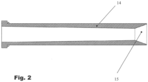
- the connecting channel 11 between the outlet 12 of the sealant container 6 and the pressure line 2 of the compressor is designed as a tubular cavity, with the valve seat 15 being formed by one end of a piece of pipe 14 inserted into the connecting channel 11 and corresponding at the end to a spherical valve body 13.
- the valve thus has a ball that can move in a cavity as the valve body and can be closed by pressing the ball, depending on gravity and position, into a valve seat 15 of the tube piece 14 that corresponds to the ball surface.
- a valve seat 15 of the tube piece 14 that corresponds to the ball surface.
- the piece of pipe 14 is shown in more detail as an individual part in an enlarged view.
- the valve seat 15 can also be seen there particularly well.
- valve and distributor unit is therefore arranged between the outlet of the sealant container and the outlet valve of the compressor (not shown here) and also between the pressure gauge and the outlet of the sealant container, with the valve seat on the side of the pressure gauge or the compressor is located.
- a valve can also be used between the compressor outlet and the pressure gauge, but then Sensitive manometer parts not protected against sealant backflow.
Landscapes
- Engineering & Computer Science (AREA)
- Mechanical Engineering (AREA)
Applications Claiming Priority (2)
| Application Number | Priority Date | Filing Date | Title |
|---|---|---|---|
| DE201310223107 DE102013223107A1 (de) | 2013-11-13 | 2013-11-13 | Vorrichtung zum Abdichten und Aufpumpen aufblasbarer Gegenstände mit Lageventil |
| PCT/EP2014/067697 WO2015070999A1 (de) | 2013-11-13 | 2014-08-20 | Vorrichtung zum abdichten und aufpumpen aufblasbarer gegenstände mit lageventil |
Publications (2)
| Publication Number | Publication Date |
|---|---|
| EP3068615A1 EP3068615A1 (de) | 2016-09-21 |
| EP3068615B1 true EP3068615B1 (de) | 2023-05-17 |
Family
ID=51392241
Family Applications (1)
| Application Number | Title | Priority Date | Filing Date |
|---|---|---|---|
| EP14755052.9A Active EP3068615B1 (de) | 2013-11-13 | 2014-08-20 | Vorrichtung zum abdichten und aufpumpen aufblasbarer gegenstände mit lageventil |
Country Status (5)
| Country | Link |
|---|---|
| EP (1) | EP3068615B1 (cg-RX-API-DMAC7.html) |
| JP (1) | JP6505099B2 (cg-RX-API-DMAC7.html) |
| CN (1) | CN105745062B (cg-RX-API-DMAC7.html) |
| DE (1) | DE102013223107A1 (cg-RX-API-DMAC7.html) |
| WO (1) | WO2015070999A1 (cg-RX-API-DMAC7.html) |
Families Citing this family (1)
| Publication number | Priority date | Publication date | Assignee | Title |
|---|---|---|---|---|
| DE102017212040A1 (de) * | 2017-07-13 | 2019-01-17 | Continental Reifen Deutschland Gmbh | Verfahren zur gewichtsabhängigen Regelung des Innendrucks eines durch eine Gewichts- oder Traglast belasteten Tragkörpers |
Citations (1)
| Publication number | Priority date | Publication date | Assignee | Title |
|---|---|---|---|---|
| JP2010023244A (ja) * | 2008-07-15 | 2010-02-04 | Sumitomo Rubber Ind Ltd | シーリング剤容器の蓋ユニット |
Family Cites Families (11)
| Publication number | Priority date | Publication date | Assignee | Title |
|---|---|---|---|---|
| DE29812740U1 (de) | 1998-07-17 | 1998-10-29 | Continental Aktiengesellschaft, 30165 Hannover | Reparatursatz mit einem tragbaren Behälter |
| PL202965B1 (pl) * | 2001-02-16 | 2009-08-31 | Continental Ag | Urządzenie do uszczelniania i napełniania obiektu nadmuchiwalnego oraz sposób uszczelniania i napełniania obiektu nadmuchiwalnego |
| ITTO20060662A1 (it) * | 2006-09-18 | 2008-03-19 | Tek Srl | Kit per la riparazione e il gonfiaggio di articoli gonfiabili |
| US20080230142A1 (en) * | 2007-03-19 | 2008-09-25 | Scott Noble Hickman | Tire sealant and air dispenser apparatus with a sealing mechanism |
| DE102007053241A1 (de) * | 2007-11-06 | 2009-05-07 | Continental Aktiengesellschaft | Vorrichtung mit einer Ventileinheit zum Abdichten und Aufpumpen aufblasbarer Gegenstände |
| EP2090419B1 (en) * | 2008-02-14 | 2013-12-25 | Sumitomo Rubber Industries, Ltd. | Sealing apparatus |
| JP2009208343A (ja) * | 2008-03-04 | 2009-09-17 | Bridgestone Corp | シーリング・ポンプアップ装置 |
| DE202008012804U1 (de) * | 2008-09-26 | 2009-02-12 | Wang, Min-Hsieng | Dose für Autoreifenabdichtmittel |
| GB2482016A (en) * | 2010-07-16 | 2012-01-18 | David Leslie White | Device for dispensing liquids |
| DE102011001603A1 (de) * | 2010-11-15 | 2012-05-16 | Illinois Tool Works, Inc. | Vorrichtung zum Ausbringen von Reifendichtmittel aus einem Behälter |
| CN102673532B (zh) * | 2011-03-14 | 2016-08-03 | 胎意科汽车配件(上海)有限公司 | 用于对可充气物品进行修理和充气的具有改进的阀的密封剂容器单元 |
-
2013
- 2013-11-13 DE DE201310223107 patent/DE102013223107A1/de not_active Withdrawn
-
2014
- 2014-08-20 CN CN201480062193.1A patent/CN105745062B/zh active Active
- 2014-08-20 JP JP2016530153A patent/JP6505099B2/ja active Active
- 2014-08-20 EP EP14755052.9A patent/EP3068615B1/de active Active
- 2014-08-20 WO PCT/EP2014/067697 patent/WO2015070999A1/de not_active Ceased
Patent Citations (1)
| Publication number | Priority date | Publication date | Assignee | Title |
|---|---|---|---|---|
| JP2010023244A (ja) * | 2008-07-15 | 2010-02-04 | Sumitomo Rubber Ind Ltd | シーリング剤容器の蓋ユニット |
Also Published As
| Publication number | Publication date |
|---|---|
| JP6505099B2 (ja) | 2019-04-24 |
| CN105745062B (zh) | 2018-05-11 |
| EP3068615A1 (de) | 2016-09-21 |
| DE102013223107A1 (de) | 2015-05-13 |
| JP2016536167A (ja) | 2016-11-24 |
| CN105745062A (zh) | 2016-07-06 |
| WO2015070999A1 (de) | 2015-05-21 |
Similar Documents
| Publication | Publication Date | Title |
|---|---|---|
| EP2807018B1 (de) | Rückflusssicherung | |
| EP2217431B1 (de) | Vorrichtung mit einer ventileinheit zum abdichten und aufpumpen aufblasbarer gegenstände | |
| EP3383630B1 (de) | Vorrichtung zum abdichten und aufpumpen von kraftfahrzeugreifen | |
| WO2009065653A1 (de) | Vorrichtung mit einer schaltmarkierung zum abdichten und aufpumpen aufblasbarer gegenstände | |
| DE10110713C2 (de) | Handpumpe mit automatischer und Handaufpumpfunktion | |
| EP2276624B1 (de) | Pannenhilfesystem | |
| EP2158073A2 (de) | Reifenabdichtvorrichtung | |
| EP3068616B1 (de) | Vorrichtung zum abdichten und aufpumpen aufblasbarer gegenstände | |
| DE102010039854A1 (de) | Rad mit einer Vorrichtung zur Reifendruckeinstellung | |
| EP3068615B1 (de) | Vorrichtung zum abdichten und aufpumpen aufblasbarer gegenstände mit lageventil | |
| DE202021103585U1 (de) | Vorrichtung für ein Luftabgaberohr eines Luftkompressors zum Aufpumpen von Reifen | |
| EP3303005B1 (de) | Drucksicherungs-vorrichtung für druckluft gefüllte räder und verfahren dazu | |
| DE102015220060A1 (de) | Reifenanschlussventil | |
| WO2006133961A2 (de) | Einrichtung zum zuführen von dichtungsflüssigkeit in einen luftreifen | |
| DE102007003667A1 (de) | Vorrichtung zum Abdichten und Aufpumpen aufblasbarer Gegenstände | |
| EP2212101B1 (de) | Vorrichtung mit einer steckverbindung zum abdichten und aufpumpen aufblasbarer gegenstände | |
| EP1997611B1 (de) | Reifenpannenhilfeset | |
| DE202004009114U1 (de) | Reifenabdichteinheit | |
| DE1855434U (de) | Geraet zur abgabe eines unter druck stehenden gasfoermigen mediums, wie insbesondere druckluft od. dgl. | |
| DE202015009957U1 (de) | Vorrichtung zum Abdichten und Aufpumpen von Kraftfahrzeugreifen | |
| DE202009009325U1 (de) | Abfülleinrichtung für Druckgasbehälter | |
| DE2651520A1 (de) | Vorrichtung fuer fahrzeugraeder | |
| DE102014109358A1 (de) | Kraftfahrzeug mit einer Reifenmess- und befüllvorrichtung | |
| DE20106601U1 (de) | Pannensicherer Fahrradschlauch und Felge | |
| DE2947218A1 (de) | Druckgasbefuellvorrichtung |
Legal Events
| Date | Code | Title | Description |
|---|---|---|---|
| PUAI | Public reference made under article 153(3) epc to a published international application that has entered the european phase |
Free format text: ORIGINAL CODE: 0009012 |
|
| 17P | Request for examination filed |
Effective date: 20160613 |
|
| AK | Designated contracting states |
Kind code of ref document: A1 Designated state(s): AL AT BE BG CH CY CZ DE DK EE ES FI FR GB GR HR HU IE IS IT LI LT LU LV MC MK MT NL NO PL PT RO RS SE SI SK SM TR |
|
| AX | Request for extension of the european patent |
Extension state: BA ME |
|
| RIN1 | Information on inventor provided before grant (corrected) |
Inventor name: ZAUM, CHRISTOPHER Inventor name: DETERING, RAINER |
|
| DAX | Request for extension of the european patent (deleted) | ||
| STAA | Information on the status of an ep patent application or granted ep patent |
Free format text: STATUS: EXAMINATION IS IN PROGRESS |
|
| 17Q | First examination report despatched |
Effective date: 20170710 |
|
| RAP1 | Party data changed (applicant data changed or rights of an application transferred) |
Owner name: CONTINENTAL REIFEN DEUTSCHLAND GMBH |
|
| GRAP | Despatch of communication of intention to grant a patent |
Free format text: ORIGINAL CODE: EPIDOSNIGR1 |
|
| STAA | Information on the status of an ep patent application or granted ep patent |
Free format text: STATUS: GRANT OF PATENT IS INTENDED |
|
| INTG | Intention to grant announced |
Effective date: 20230102 |
|
| RIN1 | Information on inventor provided before grant (corrected) |
Inventor name: DETERING, RAINER Inventor name: ZAUM, CHRISTOPHER |
|
| GRAS | Grant fee paid |
Free format text: ORIGINAL CODE: EPIDOSNIGR3 |
|
| GRAA | (expected) grant |
Free format text: ORIGINAL CODE: 0009210 |
|
| STAA | Information on the status of an ep patent application or granted ep patent |
Free format text: STATUS: THE PATENT HAS BEEN GRANTED |
|
| AK | Designated contracting states |
Kind code of ref document: B1 Designated state(s): AL AT BE BG CH CY CZ DE DK EE ES FI FR GB GR HR HU IE IS IT LI LT LU LV MC MK MT NL NO PL PT RO RS SE SI SK SM TR |
|
| REG | Reference to a national code |
Ref country code: GB Ref legal event code: FG4D Free format text: NOT ENGLISH |
|
| REG | Reference to a national code |
Ref country code: DE Ref legal event code: R096 Ref document number: 502014016563 Country of ref document: DE |
|
| REG | Reference to a national code |
Ref country code: CH Ref legal event code: EP |
|
| REG | Reference to a national code |
Ref country code: IE Ref legal event code: FG4D Free format text: LANGUAGE OF EP DOCUMENT: GERMAN |
|
| REG | Reference to a national code |
Ref country code: AT Ref legal event code: REF Ref document number: 1568238 Country of ref document: AT Kind code of ref document: T Effective date: 20230615 |
|
| P01 | Opt-out of the competence of the unified patent court (upc) registered |
Effective date: 20230602 |
|
| REG | Reference to a national code |
Ref country code: LT Ref legal event code: MG9D |
|
| REG | Reference to a national code |
Ref country code: NL Ref legal event code: MP Effective date: 20230517 |
|
| PG25 | Lapsed in a contracting state [announced via postgrant information from national office to epo] |
Ref country code: SE Free format text: LAPSE BECAUSE OF FAILURE TO SUBMIT A TRANSLATION OF THE DESCRIPTION OR TO PAY THE FEE WITHIN THE PRESCRIBED TIME-LIMIT Effective date: 20230517 Ref country code: PT Free format text: LAPSE BECAUSE OF FAILURE TO SUBMIT A TRANSLATION OF THE DESCRIPTION OR TO PAY THE FEE WITHIN THE PRESCRIBED TIME-LIMIT Effective date: 20230918 Ref country code: NO Free format text: LAPSE BECAUSE OF FAILURE TO SUBMIT A TRANSLATION OF THE DESCRIPTION OR TO PAY THE FEE WITHIN THE PRESCRIBED TIME-LIMIT Effective date: 20230817 Ref country code: NL Free format text: LAPSE BECAUSE OF FAILURE TO SUBMIT A TRANSLATION OF THE DESCRIPTION OR TO PAY THE FEE WITHIN THE PRESCRIBED TIME-LIMIT Effective date: 20230517 Ref country code: ES Free format text: LAPSE BECAUSE OF FAILURE TO SUBMIT A TRANSLATION OF THE DESCRIPTION OR TO PAY THE FEE WITHIN THE PRESCRIBED TIME-LIMIT Effective date: 20230517 |
|
| PG25 | Lapsed in a contracting state [announced via postgrant information from national office to epo] |
Ref country code: RS Free format text: LAPSE BECAUSE OF FAILURE TO SUBMIT A TRANSLATION OF THE DESCRIPTION OR TO PAY THE FEE WITHIN THE PRESCRIBED TIME-LIMIT Effective date: 20230517 Ref country code: PL Free format text: LAPSE BECAUSE OF FAILURE TO SUBMIT A TRANSLATION OF THE DESCRIPTION OR TO PAY THE FEE WITHIN THE PRESCRIBED TIME-LIMIT Effective date: 20230517 Ref country code: LV Free format text: LAPSE BECAUSE OF FAILURE TO SUBMIT A TRANSLATION OF THE DESCRIPTION OR TO PAY THE FEE WITHIN THE PRESCRIBED TIME-LIMIT Effective date: 20230517 Ref country code: LT Free format text: LAPSE BECAUSE OF FAILURE TO SUBMIT A TRANSLATION OF THE DESCRIPTION OR TO PAY THE FEE WITHIN THE PRESCRIBED TIME-LIMIT Effective date: 20230517 Ref country code: IS Free format text: LAPSE BECAUSE OF FAILURE TO SUBMIT A TRANSLATION OF THE DESCRIPTION OR TO PAY THE FEE WITHIN THE PRESCRIBED TIME-LIMIT Effective date: 20230917 Ref country code: HR Free format text: LAPSE BECAUSE OF FAILURE TO SUBMIT A TRANSLATION OF THE DESCRIPTION OR TO PAY THE FEE WITHIN THE PRESCRIBED TIME-LIMIT Effective date: 20230517 Ref country code: GR Free format text: LAPSE BECAUSE OF FAILURE TO SUBMIT A TRANSLATION OF THE DESCRIPTION OR TO PAY THE FEE WITHIN THE PRESCRIBED TIME-LIMIT Effective date: 20230818 |
|
| PG25 | Lapsed in a contracting state [announced via postgrant information from national office to epo] |
Ref country code: FI Free format text: LAPSE BECAUSE OF FAILURE TO SUBMIT A TRANSLATION OF THE DESCRIPTION OR TO PAY THE FEE WITHIN THE PRESCRIBED TIME-LIMIT Effective date: 20230517 |
|
| PG25 | Lapsed in a contracting state [announced via postgrant information from national office to epo] |
Ref country code: SK Free format text: LAPSE BECAUSE OF FAILURE TO SUBMIT A TRANSLATION OF THE DESCRIPTION OR TO PAY THE FEE WITHIN THE PRESCRIBED TIME-LIMIT Effective date: 20230517 |
|
| PG25 | Lapsed in a contracting state [announced via postgrant information from national office to epo] |
Ref country code: SM Free format text: LAPSE BECAUSE OF FAILURE TO SUBMIT A TRANSLATION OF THE DESCRIPTION OR TO PAY THE FEE WITHIN THE PRESCRIBED TIME-LIMIT Effective date: 20230517 Ref country code: SK Free format text: LAPSE BECAUSE OF FAILURE TO SUBMIT A TRANSLATION OF THE DESCRIPTION OR TO PAY THE FEE WITHIN THE PRESCRIBED TIME-LIMIT Effective date: 20230517 Ref country code: RO Free format text: LAPSE BECAUSE OF FAILURE TO SUBMIT A TRANSLATION OF THE DESCRIPTION OR TO PAY THE FEE WITHIN THE PRESCRIBED TIME-LIMIT Effective date: 20230517 Ref country code: EE Free format text: LAPSE BECAUSE OF FAILURE TO SUBMIT A TRANSLATION OF THE DESCRIPTION OR TO PAY THE FEE WITHIN THE PRESCRIBED TIME-LIMIT Effective date: 20230517 Ref country code: DK Free format text: LAPSE BECAUSE OF FAILURE TO SUBMIT A TRANSLATION OF THE DESCRIPTION OR TO PAY THE FEE WITHIN THE PRESCRIBED TIME-LIMIT Effective date: 20230517 Ref country code: CZ Free format text: LAPSE BECAUSE OF FAILURE TO SUBMIT A TRANSLATION OF THE DESCRIPTION OR TO PAY THE FEE WITHIN THE PRESCRIBED TIME-LIMIT Effective date: 20230517 |
|
| REG | Reference to a national code |
Ref country code: DE Ref legal event code: R097 Ref document number: 502014016563 Country of ref document: DE |
|
| PG25 | Lapsed in a contracting state [announced via postgrant information from national office to epo] |
Ref country code: MC Free format text: LAPSE BECAUSE OF FAILURE TO SUBMIT A TRANSLATION OF THE DESCRIPTION OR TO PAY THE FEE WITHIN THE PRESCRIBED TIME-LIMIT Effective date: 20230517 |
|
| RAP4 | Party data changed (patent owner data changed or rights of a patent transferred) |
Owner name: CONTINENTAL REIFEN DEUTSCHLAND GMBH |
|
| REG | Reference to a national code |
Ref country code: DE Ref legal event code: R081 Ref document number: 502014016563 Country of ref document: DE Owner name: CONTINENTAL REIFEN DEUTSCHLAND GMBH, DE Free format text: FORMER OWNER: CONTINENTAL REIFEN DEUTSCHLAND GMBH, 30165 HANNOVER, DE |
|
| PLBE | No opposition filed within time limit |
Free format text: ORIGINAL CODE: 0009261 |
|
| STAA | Information on the status of an ep patent application or granted ep patent |
Free format text: STATUS: NO OPPOSITION FILED WITHIN TIME LIMIT |
|
| REG | Reference to a national code |
Ref country code: CH Ref legal event code: PL |
|
| PG25 | Lapsed in a contracting state [announced via postgrant information from national office to epo] |
Ref country code: MC Free format text: LAPSE BECAUSE OF FAILURE TO SUBMIT A TRANSLATION OF THE DESCRIPTION OR TO PAY THE FEE WITHIN THE PRESCRIBED TIME-LIMIT Effective date: 20230517 |
|
| PG25 | Lapsed in a contracting state [announced via postgrant information from national office to epo] |
Ref country code: LU Free format text: LAPSE BECAUSE OF NON-PAYMENT OF DUE FEES Effective date: 20230820 |
|
| 26N | No opposition filed |
Effective date: 20240220 |
|
| GBPC | Gb: european patent ceased through non-payment of renewal fee |
Effective date: 20230820 |
|
| PG25 | Lapsed in a contracting state [announced via postgrant information from national office to epo] |
Ref country code: LU Free format text: LAPSE BECAUSE OF NON-PAYMENT OF DUE FEES Effective date: 20230820 Ref country code: CH Free format text: LAPSE BECAUSE OF NON-PAYMENT OF DUE FEES Effective date: 20230831 |
|
| PG25 | Lapsed in a contracting state [announced via postgrant information from national office to epo] |
Ref country code: SI Free format text: LAPSE BECAUSE OF FAILURE TO SUBMIT A TRANSLATION OF THE DESCRIPTION OR TO PAY THE FEE WITHIN THE PRESCRIBED TIME-LIMIT Effective date: 20230517 |
|
| REG | Reference to a national code |
Ref country code: BE Ref legal event code: MM Effective date: 20230831 |
|
| REG | Reference to a national code |
Ref country code: IE Ref legal event code: MM4A |
|
| PG25 | Lapsed in a contracting state [announced via postgrant information from national office to epo] |
Ref country code: SI Free format text: LAPSE BECAUSE OF FAILURE TO SUBMIT A TRANSLATION OF THE DESCRIPTION OR TO PAY THE FEE WITHIN THE PRESCRIBED TIME-LIMIT Effective date: 20230517 Ref country code: IT Free format text: LAPSE BECAUSE OF FAILURE TO SUBMIT A TRANSLATION OF THE DESCRIPTION OR TO PAY THE FEE WITHIN THE PRESCRIBED TIME-LIMIT Effective date: 20230517 |
|
| PG25 | Lapsed in a contracting state [announced via postgrant information from national office to epo] |
Ref country code: IE Free format text: LAPSE BECAUSE OF NON-PAYMENT OF DUE FEES Effective date: 20230820 |
|
| PG25 | Lapsed in a contracting state [announced via postgrant information from national office to epo] |
Ref country code: GB Free format text: LAPSE BECAUSE OF NON-PAYMENT OF DUE FEES Effective date: 20230820 |
|
| PG25 | Lapsed in a contracting state [announced via postgrant information from national office to epo] |
Ref country code: IE Free format text: LAPSE BECAUSE OF NON-PAYMENT OF DUE FEES Effective date: 20230820 Ref country code: GB Free format text: LAPSE BECAUSE OF NON-PAYMENT OF DUE FEES Effective date: 20230820 Ref country code: FR Free format text: LAPSE BECAUSE OF NON-PAYMENT OF DUE FEES Effective date: 20230831 |
|
| PG25 | Lapsed in a contracting state [announced via postgrant information from national office to epo] |
Ref country code: BE Free format text: LAPSE BECAUSE OF NON-PAYMENT OF DUE FEES Effective date: 20230831 |
|
| REG | Reference to a national code |
Ref country code: AT Ref legal event code: MM01 Ref document number: 1568238 Country of ref document: AT Kind code of ref document: T Effective date: 20230820 |
|
| PG25 | Lapsed in a contracting state [announced via postgrant information from national office to epo] |
Ref country code: AT Free format text: LAPSE BECAUSE OF NON-PAYMENT OF DUE FEES Effective date: 20230820 |
|
| PG25 | Lapsed in a contracting state [announced via postgrant information from national office to epo] |
Ref country code: AT Free format text: LAPSE BECAUSE OF NON-PAYMENT OF DUE FEES Effective date: 20230820 |
|
| PG25 | Lapsed in a contracting state [announced via postgrant information from national office to epo] |
Ref country code: BG Free format text: LAPSE BECAUSE OF FAILURE TO SUBMIT A TRANSLATION OF THE DESCRIPTION OR TO PAY THE FEE WITHIN THE PRESCRIBED TIME-LIMIT Effective date: 20230517 |
|
| PG25 | Lapsed in a contracting state [announced via postgrant information from national office to epo] |
Ref country code: BG Free format text: LAPSE BECAUSE OF FAILURE TO SUBMIT A TRANSLATION OF THE DESCRIPTION OR TO PAY THE FEE WITHIN THE PRESCRIBED TIME-LIMIT Effective date: 20230517 |
|
| PG25 | Lapsed in a contracting state [announced via postgrant information from national office to epo] |
Ref country code: CY Free format text: LAPSE BECAUSE OF FAILURE TO SUBMIT A TRANSLATION OF THE DESCRIPTION OR TO PAY THE FEE WITHIN THE PRESCRIBED TIME-LIMIT; INVALID AB INITIO Effective date: 20140820 |
|
| PG25 | Lapsed in a contracting state [announced via postgrant information from national office to epo] |
Ref country code: HU Free format text: LAPSE BECAUSE OF FAILURE TO SUBMIT A TRANSLATION OF THE DESCRIPTION OR TO PAY THE FEE WITHIN THE PRESCRIBED TIME-LIMIT; INVALID AB INITIO Effective date: 20140820 |
|
| PGFP | Annual fee paid to national office [announced via postgrant information from national office to epo] |
Ref country code: DE Payment date: 20250831 Year of fee payment: 12 |
|
| PG25 | Lapsed in a contracting state [announced via postgrant information from national office to epo] |
Ref country code: TR Free format text: LAPSE BECAUSE OF FAILURE TO SUBMIT A TRANSLATION OF THE DESCRIPTION OR TO PAY THE FEE WITHIN THE PRESCRIBED TIME-LIMIT Effective date: 20230517 |