EP3067486B1 - Securing for grating - Google Patents
Securing for grating Download PDFInfo
- Publication number
- EP3067486B1 EP3067486B1 EP16160203.2A EP16160203A EP3067486B1 EP 3067486 B1 EP3067486 B1 EP 3067486B1 EP 16160203 A EP16160203 A EP 16160203A EP 3067486 B1 EP3067486 B1 EP 3067486B1
- Authority
- EP
- European Patent Office
- Prior art keywords
- securing
- section
- grating
- fastening device
- component
- Prior art date
- Legal status (The legal status is an assumption and is not a legal conclusion. Google has not performed a legal analysis and makes no representation as to the accuracy of the status listed.)
- Active
Links
Images


Classifications
-
- E—FIXED CONSTRUCTIONS
- E04—BUILDING
- E04C—STRUCTURAL ELEMENTS; BUILDING MATERIALS
- E04C2/00—Building elements of relatively thin form for the construction of parts of buildings, e.g. sheet materials, slabs, or panels
- E04C2/30—Building elements of relatively thin form for the construction of parts of buildings, e.g. sheet materials, slabs, or panels characterised by the shape or structure
- E04C2/42—Gratings; Grid-like panels
- E04C2/428—Separate connecting means, e.g. connecting gratings to underlying structure
-
- E—FIXED CONSTRUCTIONS
- E04—BUILDING
- E04F—FINISHING WORK ON BUILDINGS, e.g. STAIRS, FLOORS
- E04F17/00—Vertical ducts; Channels, e.g. for drainage
- E04F17/06—Light shafts, e.g. for cellars
-
- E—FIXED CONSTRUCTIONS
- E05—LOCKS; KEYS; WINDOW OR DOOR FITTINGS; SAFES
- E05B—LOCKS; ACCESSORIES THEREFOR; HANDCUFFS
- E05B65/00—Locks or fastenings for special use
- E05B65/10—Locks or fastenings for special use for panic or emergency doors
- E05B65/1033—Locks or fastenings for special use for panic or emergency doors emergency release of windows, window grills, escape hatches or the like
Definitions
- the present invention relates to a fastening device for securing a first component with a lattice structure on a second component, in particular for securing a grating in a light shaft according to claim 1.
- Grating fastening devices are known from the prior art and are used primarily, but not only, to secure a grating in a light shaft, against the forcible removal of the grating by unauthorized persons. It is also conceivable to use it to secure crates, for example cellar compartment grids or other barriers.
- fastening devices are formed, for example, in the form of hook-shaped or multi-part plate-like constructions from a plate and a rod.
- Fastening devices of the generic type are designed in such a way that a square or round plate is applied to the lattice structure of a first component from above and is clamped down through the lattice structure to a second component via a fastening structure in the form of a chain or a metal strip.
- Generic fastening devices are for example in the utility model DE 76 38 968 U , the utility model DE 77 13 327 U as well as the utility model DE 77 38 787 U1 disclosed. These show various designs of safety devices for gratings, consisting of a rod-like element and a plate, the plate being placed above the lattice structure and through for anchoring from below with a rod or the like the grating is tensioned through and fixed to a wall of the light shaft.
- Another known possibility is a design as a simple hook, which is hung on a rod section of the lattice structure and attached and fixed downwards to a second component.
- the utility model GM 75 30 970 discloses a holding device for grids on shafts or the like.
- the holding device engages around the grating in the shape of a hook by means of a holding rod designed in the form of a hook.
- This holding rod is provided with a clamping screw for fastening to, for example, shaft walls.
- the screw head is covered and thus secured by a wing consisting of an angle piece.
- the opposing hook legs can be fixed to one another by a connecting screw.
- a holding device with a U-shaped hook in which both hook ends extend down to the bracing and are anchored there.
- the U-shaped hook is connected to the grating via a rod section.
- the DE 40 06 321 A1 describes a safety device for cellar gratings, comprising a grid safety section and a train safety section.
- a slotted hook which forms the lattice securing section
- the securing device can overlap two rod sections of the lattice structure.
- the hook is slotted on the two vertically parallel sections.
- a cover plate can be welded onto the top of the hook in order to cover a larger surface of the lattice structure.
- the hook can be detachably hooked into the tension protection section and can be inserted through the grid from above.
- Providing a plurality of hooks to grip around a plurality of rod sections is not envisaged. With such a safety device only two rod sections can be enclosed.
- the holding device in the DE 28 49 878 C2 engages around the grating in the shape of a hook by means of a slotted holding rod designed in the shape of a hook. This allows two bars to be enclosed at the same time.
- the support rod is provided with a clamping screw for fastening to the shaft walls using an angle piece.
- the hook can be slotted and enclose at least one rod section of the grating.
- a holding device of this type does not encompass a large number of rod sections.
- connection element for gratings to be attached to ceilings, so-called ceiling support structure of grid grids.
- the connecting element is designed in one piece as an elongated sheet metal and comprises a slotted hook at one end for grasping adjacent bars.
- the hook can therefore encompass two rod sections of the grating.
- the connecting element has a bending bead which can be pushed into a retaining rail curved in a complementary manner.
- the disclosure shows a non-generic ceiling support structure of grid grids, in which the holding device is attached above the grating and, moreover, no one-piece design of a hook comb.
- the DE 75 01 257 U shows a securing device for gratings, comprising a grating securing section and a train securing section.
- the lattice securing section has a hook which can engage in a rod section of the lattice structure and which can be hooked into a tension securing section.
- a grip of three or more rod sections is not given with such a design.
- the DE 90 02 369 U1 discloses a securing device for securing a grating in a light shaft.
- This has a slotted safety hook with a head-side arranged, for. B. welded, cover plate.
- the safety hook is slotted in a plane running at right angles to the grating plane. Due to the slotted design, the securing hook can encompass two rod sections of the grating in a U-shape.
- the safety hook is attached to the shaft wall with a pull safety section.
- the train protection section an opening into which the locking hook engages and hooks.
- a safety device with an L-shaped safety bracket.
- the safety bracket runs partially parallel to the shaft wall and partially parallel to the underside of the grating.
- a cover plate can be attached between the grating and bracket and above the grating, which covers the meshes of the grating in this area and which is connected to the safety bracket and the grating with at least two tensioning screws.
- the DE 29 13 112 A1 likewise shows a securing device for a grating of a cellar shaft with an L-shaped securing bracket.
- the horizontal section of the safety bracket is connected by a bolt to a cover plate which is attached above the grating and has a hole.
- the bolt is screwed with a nut and a lock nut underneath the grating.
- An eyelet or the like is mounted on the inside of the light well so that the eyelet can be pushed into a recess in the safety bracket and secured with a lock.
- the US 5 911 664 A shows a fastening system for a grating with an integrated frame component for the formation of a running surface in an area that can be washed over by water, such as a gangway, a railing staircase, in swimming platforms or the like. Due to the susceptibility of metal grids to corrosion in this area, a grating made of fiberglass is used. Furthermore, the grating is mechanically fastened to the frame component with a terminal strip.
- this component can be bent or levered out of its plane by unauthorized persons and rotated around the axis of rotation thus formed so that unauthorized persons can enter the building through the light shaft or the basement window.
- the plate-like designs consisting of at least one plate and a holding rod as well as further fixing elements and profiles, are constructed in several parts, which increases the manufacturing costs and the assembly effort and makes assembly more difficult.
- a large number of fastening devices also restrict the incidence of light through the grid structure and thus into the light shaft or the basement window.
- the object of the invention is to overcome the disadvantages of the known arrangements.
- Another task here is not to unnecessarily restrict the incidence of light into the light shaft through the lattice structure of the first component.
- the aim is also to provide a fastening device for securing a grating or the like, whereby a security against the intrusion of unauthorized persons with a resistance class 3 or higher according to DIN EN 1627 or DIN V ENV 1627 in the version of the year 2016 can be achieved.
- DIN EN 1627 or DIN V ENV 1627 in the version of the year 2016 can be achieved.
- a fastening device for securing a first component with a lattice structure, comprising a plurality of meshes delimited by rod sections on a second component, the first component being a grating and the second component being a light shaft, the fastening device being a grid securing section for connecting the Fastening device with the lattice structure and a tension securing section for connecting the fastening device to the second component, wherein the lattice securing section is formed in one piece or in several parts.
- the grid securing section has at least three to ten, in particular seven or eight securing units, which are detachably and / or non-detachably connected to a base body of the grid securing section, in particular screwed, riveted, welded or soldered and which are each connected to a rod section of the
- the lattice structure can be connected, the lattice securing section being plate-shaped and the securing units being shaped and attached to a longitudinal edge of the lattice securing section in such a way that they can enclose several rod sections of the lattice structure in a comb-like manner and each securing unit is U-hook-shaped in the end area and a rod section of the first component is at least partially and only the comb-like securing units without planar components are visible from a position above the first component, so that light does not enter the lattice structure is limited and optically the fuse units are barely perceived, and at least three rod sections of the lattice
- a one-piece design of the lattice securing section enables simple assembly and inexpensive manufacture of the fastening device.
- a multi-part design of the lattice securing section enables easier assembly, as well as scaling and adaptability of the lattice securing device.
- the grid securing section can preferably be straight, but curved or curved arrangements of the securing units of the grid securing section are also conceivable.
- the grid securing section can also have a rounded shape and have the shape of a pipe section, or the grid securing section can be angled.
- the lattice securing section in the form of a cylinder, for example as a tubular or rectangular cylinder, are also conceivable, the upper edge of the lattice securing section having a plurality of securing units which can be used for fastening to rod sections of the first component.
- the securing units can be detachably and / or non-detachably connected to the base body of the grid securing section.
- the fuse units can be screwed, riveted, welded or soldered on.
- safety screws or bolts or screws in conjunction with shear nuts, shear bolts or the like can be used when assembling the securing sections.
- safety screws have a special screw head with a special screw head drive, for example in the form of an internal multi-tooth or a Torx with a pin or pin.
- a special screw head drive for example in the form of an internal multi-tooth or a Torx with a pin or pin.
- Such safety screws are difficult to dismantle or cannot be dismantled simply by unscrewing them using special tools, shear nuts or bolts.
- the respective rod section is securely encompassed or encompassed and the meshes of the lattice structure are hardly covered, so that the incidence of light into the lattice structure is not restricted becomes.
- the end regions of the U-shaped securing units preferably overlap the rod sections of the lattice structure by at least an additional 5 mm so that the end regions can no longer be bent open by force.
- a connecting screw can be used to fix the end areas of the U-shaped securing units with the respective opposite areas of the respective securing unit with a screw, rivet, wire or rope, so that the rod sections are encompassed all around by the securing unit.
- a short long side of a first component, especially a grating, with eight safety units can secure a grating width of approx. 30 cm very well.
- a possible intruder would have to cut through almost the entire grating twice in width, which would require at least twenty cuts.
- the number of rod sections to be cut when removing the lattice structure from the mounted fastening device is twice the number of securing units plus at least four rod sections in the edge area.
- a lattice structure in particular of a light shaft lattice, comprises mechanically reinforced support rods as longitudinal rods for receiving a support weight and transverse rods for connecting the support rods.
- the height of the support rods is greater than that of the transverse rods, and the width of a support rod can also be greater than that of a transverse rod.
- the lattice securing section is plate-shaped and the securing units are shaped and attached to a longitudinal edge of the lattice securing section in such a way that they can enclose several rod sections of the lattice structure in a comb-like manner.
- the incidence of light is hardly restricted by such a slim design of the fuse units and the fuse unit is hardly noticeable optically, since only the comb-like design of the fuse units without flat components is visible from a position above the first component.
- a comb-like one Execution of the fuse units enables a simple manufacturing process from only one component and a simple assembly of a linear mounting of the construction in the lattice structure without pre-assembly of individual components of the lattice fuse section.
- the plate of the grid fuse section can be flat and thus define a linear arrangement of the fuse units.
- the plate can also be curved, angled or closed in itself to form a cylinder which, for example, can be round or rectangular.
- At least one securing unit preferably at least two securing units, each with at least one safety screw or one screw in connection with a shear nut or shear screw can be attached to the base body of the lattice securing section.
- Safety screws are easy to assemble with standard tools, but are very difficult to remove after assembly. With shear nuts, a conical nut remains after assembly, which can no longer be dismantled with standard tools. Securing objects against unintentional dismantling is possible with these screw-on shear nuts or shear bolts.
- the safety screw can be mounted from any side, ie from the side of the base body of the grid securing section or from the side of the securing units. From the side of the grating facing away from the light shaft, it is almost impossible to loosen such a safety screw with one hand. For a two-handed dismantling, an unauthorized person would have to make a very large recess in the grating, which involves a lot of time.
- At least one of the safety screws, screws or bolts can simultaneously fasten the tension protection section to the base body of the grid protection section if the tension protection section and the grid protection section are formed from at least two separate components.
- the grid securing section and the train securing section can be formed from separate components. This enables a flexible design of the train protection section.
- the train protection section can be designed in one or more parts and can be adapted to different geometries of the edge areas of the light shaft.
- the train protection section can be exchanged flexibly. Several grid protection units can thus also be secured with a common train protection section.
- the grid securing section and the at least one tension securing section can be connected to one another by a force-fit connection that cannot be released without tools, in particular a screw or rivet connection.
- the two-part design of the lattice securing section and the tension securing section enables a flexible design of both sections.
- the screw or rivet head can be covered by a wing, consisting for example of an angle piece, and thus secured against dismantling from an unauthorized position above the lattice structure.
- the grid securing section and the train securing section can be connected to one another by means of a flexible chain or rope connection, which in particular opens up the possibility of several grid securing sections being connected to one train securing section.
- the lattice securing section has at least one recess in the form of a hook, into which the at least one tension securing section can be hooked or with which the tension securing section can be attached to the lattice securing section.
- the tension protection section can be formed from a rod-like, rope-like, profile-like or chain-like component.
- the tension protection section can be flexibly adapted to different geometrical shapes of the second component and can be attached to this second component, for example by means of a dowel connection, bolt connection or an anchor connection.
- the train protection section can be flexibly exchanged or retensioned.
- the tension protection section can be adjustable and fixable in length via at least one long nut and at least one eyebolt.
- a long nut with at least one eyelet can be mounted between one end of the tension protection section and a second component, for example the wall of a light shaft, in order to adjust the length of the tension protection section variably and to fix it in a desired length.
- An eyebolt is preferably mounted on each side of the long nut, with the chain-like component being able to be hooked into one eyebolt and attachment to a second component being possible on the other eyebolt.
- the tension protection section By turning at least one eyebolt against the long nut, the tension protection section can be pretensioned and fixed in a desired length.
- the attachment to a second component, such as the wall of a light shaft, can be carried out using a heavy-duty dowel, for example a bolt anchor or a hanger bolt.
- a shear nut can be fitted to both ends of the long nut and act as a lock nut. The long nut cannot be twisted against the eye bolts and can therefore only be dismantled with difficulty by unauthorized persons.
- the tension securing section can be attached to a wall of the light shaft with at least one heavy-duty dowel, in particular a bolt anchor or a hanger bolt, with or without a split pin hole for the implementation of a clamping sleeve or a split pin or spring split pin.
- the tension protection section can be mounted on a second component, such as the wall of a light shaft, in a safe manner. This is particularly suitable for a concrete light shaft construction.
- the bolt anchor has a thread and a nut.
- split pins are made from wire with a semicircular cross-section. The two legs of different lengths are pressed parallel to one another and form a round cross-section with a diameter specified in the standard. At one end, the wire is compressed to form an approximately circular loop, the split pin head, which also has standardized dimensions.
- the legs can be bent up against each other after being pushed through.
- a longitudinally slotted, sleeve-shaped pin is pressed into the split pin hole, whereby the clamping sleeve must protrude beyond the diameter of the heavy-duty dowel on at least one side. Due to the longitudinally slotted design, the clamping sleeve expands when installed and presses against the split pin hole. Disassembly is also only possible with a special tool, in particular a pin punch, although this is hardly possible with one hand. After installing the bolt anchor and inserting a split pin or an adapter sleeve, the nut cannot be loosened without removing the split pin.
- the cotter pin can only be removed with a pin punch. This can only be operated with two hands. Thus the bolt anchor can only be released with two hands.
- hanger bolts with or without a split pin hole or the like can also be used for secure assembly.
- the hanger bolt preferably has two threads running in opposite directions at the two ends. For an unauthorized person from the side of the grating facing away from the light shaft, an opening of the size would have to be made in the grating so that both hands could be passed through. This would take an enormous amount of time, which means an increased resistance time according to the standardized resistance classes.
- Such a secured fastening device for gratings can easily be classified in resistance class RC3 (according to DIN EN 1627) or WK3 (according to DIN V ENV 1627) or higher.
- a quick release from the inside is always possible, as two-handed assembly / disassembly from the side of the light shaft, for example through the basement window, is easily possible.
- the tension protection section can be fastened to a wall of the light shaft with at least one heavy-duty dowel such as a bolt anchor or a hanger bolt with or without a hole for the implementation of a padlock.
- at least one heavy-duty dowel such as a bolt anchor or a hanger bolt with or without a hole for the implementation of a padlock.
- a connection area of the securing unit can correspond to a length of a rod section b of the lattice structure of the first component. This allows the fuse units to be hooked into the mesh of the lattice structure with a precise fit.
- the width b of a rod section of the lattice structure can, for example, be taken from the standard DIN 24 537, status October 1991, in which the dimensions, designations and the loading of gratings are regulated. If the securing units are matched precisely to the width b of a rod section, the rod sections which are encompassed by the securing units can only be separated with great effort and expense by force using bolt cutters or the like. In addition, it is not possible to move the lattice structure transversely to the fastening device by means of such securing units.
- connection area of the fuse unit can have a width b of 25 mm to 35 mm, preferably 28 mm and a distance d of 3 mm to 6 mm, preferably 4.5 mm to the connection area of an adjacent fuse unit.
- the fuse units can be adapted to the standard specifications for the dimensions of gratings and can be used for a large number of commercially available gratings. Due to the aforementioned dimensions, there is no space left within a rod section for attaching a bolt cutter or similar material-separating tool. Moving the first component, for example the grating, relative to the securing unit is no longer possible.
- the security unit can have a width of 6 mm to 9 mm, preferably 7.5 mm To include cross bars of the lattice structure. The securing unit can then be hooked into the short cross bars of the lattice structure.
- the grid securing section can be formed from a metal sheet, in particular from a galvanized steel sheet, with the securing units being formed by cutting sheet metal tongues on a longitudinal edge of the metal sheet and bending end sections of the sheet metal tongues in the one-piece design of the grid securing section.
- individual sheet metal tongues are, for example, milled, punched, lasered or cut into the sheet metal, which can have a thickness of 3 mm, on a longitudinal edge. These sheet metal tongues are bent at their end sections and thus formed into hook-shaped securing units.
- the end sections can be formed parallel to the sheet metal tongues.
- Galvanizing increases the weather resistance and protects against corrosion.
- the grid securing portion is hardened to increase the toughness and hardness of the fastening device. Such a production method is inexpensive and involves little effort.
- the grid securing section consists of only one component and can be produced in just a few steps.
- the fastening device can thus, for example, also be attached diagonally in a rectangular lattice structure of a first component, provided that the lattice securing section is shaped in a straight line.
- the angling of the securing units is used the adaptation to the fixed position of the rod sections.
- only one fastening device can thus be sufficient to secure the grating.
- the grid securing section can be provided as a whole with an angle, in other words have a kink and, for example, be provided for an arrangement of the fastening device at a corner.
- the fastening device can thus be optimally adapted to the geometry of the grid securing section.
- several contiguous longitudinal bar sections in combination with several contiguous transverse bar sections can be comprised with the securing units.
- a rectangular grating can be secured at two diagonally opposite corners.
- At least one securing unit after connection to a rod section, preferably hanging in a rod section, can be secured against detachment, in particular against unhinging, by means of a securing bolt or a safety screw or a screw in connection with a shear nut or shear screw on the rod section will. Forcible bending of the securing units can thus be prevented, since the securing unit completely encloses the rod section and the grid securing section cannot be unhooked without first opening the screw connection or removing the bolt.
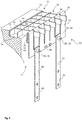
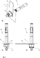
- Fig. 1 shows a fastening device 20 according to the invention in a three-panel projection with a side view Figure 1b in longitudinal section, Fig. 1a , as well as in cross section Figure 1c .
- the fastening device 20 comprises a lattice securing section 22 and a tension securing section 24.
- the lattice securing section 22 comprises a plurality of securing units 26 which are designed in the shape of a hook 32 in their end region 30.
- the hook end 30 runs parallel to the base body of the grid securing section 22.
- the grid securing section 22 comprises seven securing units 26, but embodiments with more or fewer securing units 26 are also possible.
- each securing unit 26 forms a line, so that the securing units 26 can encompass a number of contiguous longitudinal or transverse rod sections 16.
- the fuse units 26 have a width b and are arranged at a distance d from one another.
- the grid securing section 22 can be formed from a metal sheet 40, in particular from a galvanized steel sheet.
- the grid fuse section 22 and the Train securing sections 24 are connected to one another by a releasable connection 28.
- This releasable connection 28 can for example be in the form of a screw or rivet connection 38, for example with safety screws.
- the tension protection section can be formed, for example, by a rod-like, rope-like, profile-like or chain-like component.
- the train protection section 24 can be connected to a second component in the end region 46.
- the tension protection section 24 can be designed in one piece or also in several pieces.
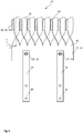
- FIG. 14 is a perspective view of the first embodiment 20 of a fastening device according to the invention Fig. 1 shown.
- the grid securing section 22 can be formed from a metal sheet 40, such as a galvanized steel sheet.
- the securing units 26 are formed by cutting sheet metal tongues 42 on a longitudinal edge 34 of the metal sheet 40 and bending end sections 44 of the sheet metal tongues 42.
- the individual sheet metal tongues 42 are milled or cut, for example, on the longitudinal edge 34.
- These sheet metal tongues 42 are bent at their end sections and thus formed into hook-shaped securing units 32.
- the end sections 44 can be formed parallel to the sheet metal tongues 42.
- the area of the end sections 44 can have a length of at least 35 mm so that the end section 44 of the sheet metal tongues 44 cannot be bent open when the fastening device 20 is installed.
- the grid securing section is connected to a tension securing section 24 via a releasable connection 28.
- screws, safety screws, bolts or rivets can be used as the detachable connection 28.
- the releasable connections 28 can preferably only be removed by means of a special tool.
- the train securing section 24 can be made in one piece or in several pieces.
- the tension protection section 24 can be formed as a sheet metal or profile component, as well as from a chain-like, rope-like or rod-like construction.
- a further protective structure can be provided around the detachable connection 28, which can prevent access to the grid and thus the detachment of the connection 28 by unauthorized persons.
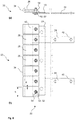
- FIG. 3 shows the first embodiment 20 of the fastening device in the installed state.
- a first component 10 is shown, comprising a lattice structure 12 and a frame 17 of the lattice structure 12, which in the edge region rests with the frame 17 on a support edge 19 of a second component 18.
- the lattice structure comprises individual meshes 14, which are formed by several rod sections 16, mostly by four rod sections 16.
- the first component 10 can form a grating for a light shaft 11 and the second component 18 the outer wall of the light shaft 11.
- the fastening device 20 is formed from a grid securing section 22 and a tension securing section 24.
- the grid securing section 22 is connected to the first component 10, which comprises a grid structure 12.
- the lattice securing section 22 comprises several securing units 26.
- the securing units 26 enclose with their end regions 30 individual rod sections 16 of the lattice structure 12.
- the securing units 26 comprise individual rod sections 16 of a contiguous row of rod sections.
- the width b of each securing unit 26 is adapted to the width of the rod sections 16 in the embodiment shown. This makes it almost impossible to sever the rod sections 16 which are enclosed by the hook-shaped securing unit 32.
- the grid securing section 22 is connected to the tension securing section 24 via a releasable connection 28.
- the tension securing section 24 can be fixed in its end region 46 on the second component 18 via bolt anchors (not shown).
- two fastening devices 20 can be attached to two opposite shaft walls of the light shaft 11.
- the number of securing units 26 can be adapted to the number of meshes 14 of the lattice structure 12 of the first component 10.
- a width of the lattice structure 12 of approximately 30 cm can be adequately secured with two fastening devices 20, each with eight securing units 26 with a width b of 29 mm each.
- the number of rod sections 16 to be cut in the event of unauthorized removal of the lattice structure 12 from the fastening device 20 is: number of securing units x 2 + 4.
- the lower edge of the lattice securing section 22 is provided with two mirror-inverted hook-shaped recesses 48 in which, for example, one or two traction safety chains or traction safety ropes can be suspended in order to fasten the lattice securing section.
- the fastening hooks 48 can be used in addition or as an alternative to the shown tension protection sections 24, which are designed in the form of flat bars or flat connectors, for tension protection of the grid protection section 22.
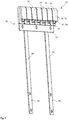
- Fig. 4 is a perspective view of another embodiment 20 of the invention shown.
- the fastening device 20 is designed in two parts, comprising a lattice securing section 22 and a tension securing section 24.
- the lattice securing section 22 comprises several securing units 26.
- the securing units 26 are arranged rotated by an angle ⁇ with respect to the base body of the lattice securing section 22.
- the longitudinal edges 34 of the fuse units 26 thus do not run in a line in the embodiment shown, but rather parallel to one another.
- the securing units 26 can encompass not only a contiguous row of longitudinal or transverse rod sections 16, but also longitudinal or transverse rod sections 16 running parallel. This can be of particular advantage if the fastening options in the light shaft 11 are not sufficient or are only available at a less than optimal location.
- the grid securing section 22 can be hung diagonally into a grid structure 12. With such an arrangement, a fastening device 20 can be sufficient for securing a first component 10 of a light shaft 11.
- the grid securing section 22 of the fastening device 20 can also have far more than seven securing units 26.
- each securing unit has a different angle ⁇ in order to be able to grip around corresponding rod sections.
- the angles can be adjusted during assembly.
- a tapering of the connection area of the fuse unit can be provided, which makes it easier to bend the fuse unit.
- Fig. 5 shows in perspective another embodiment of a fastening device 20 according to the invention.
- the grid securing section 22 and the tension securing section 24 are designed in one piece in the form of a single component.
- the fastening device 20 comprises several securing units 26 in the lattice securing section 22 and an end region 46 in the tension securing section 24 for fixing to a component.
- the end area can, for example, be fastened to the second component 18 in the light shaft 11 at several positions.
- the end area 46 is arranged in a step-like manner in a plane offset from the grid securing section 22. This prevents the end region 46 from being able to be reached from a position above the grid securing section.
- the fastening of the end region 46 to a component after the fastening device 20 has been installed in a light shaft 11 or the like cannot be released or removed by unauthorized persons.
- Fig. 6 shows a fastening device 20 according to the invention in a side view Figure 6a as well as in cross section, Figure 6b .
- the fastening device 20 comprises a lattice securing section 22 and a tension securing section 24.
- the lattice securing section 22 comprises a plurality of securing units 26 which are not formed in one piece with the base body 23 of the lattice securing section 22.
- the securing units 26 are connected to the base body 23 of the grid securing section 22 with safety screws 50 or screws 52.
- These safety screws 50 or screws 52 which are fastened with shear nuts 54, represent a difficult-to-dismantle connection between the fuse units 26 and the base body 23 of the grid fuse section 22.
- the fuse units 26 run into the end region 30 in a hook-shaped 32.
- the hook end 30 runs parallel to the base body 23 of the grid securing section 22.
- the grid securing section 22 includes seven securing units 26, but embodiments with more or fewer securing units 26 are also possible.
- the longitudinal edges 34 of each fuse unit 26 form a line, so that the securing units 26 can encompass a number of contiguous longitudinal or transverse rod sections 16.
- the fuse units 26 have a width b, which corresponds to the width of a rod section, and are arranged at a distance d from one another.
- the grid securing section 22 can be formed from a metal sheet 40, in particular from a galvanized steel sheet.
- the grid securing section 22 and the train securing section 24 are connected to one another.
- the train securing section 24 can be formed, for example, by a rod-like, rope-like, profile-like or chain-like component.
- the tension protection section 24 can be connected in the end area 46 to a second component via bolt anchors (not shown) or the like.
- the tension protection section 24 can be designed in one piece or also in several pieces.
- FIG. 13 is a perspective view of the embodiment from FIG Fig. 6 a fastening device 20 according to the invention is shown.
- FIGs. 8a and 8b a fuse unit 26 and a base element 23 of the grid fuse section 22 are shown as individual elements.
- the illustrations each show a side view and a cross-sectional illustration.
- Figure 8a shows a securing unit 26 in the form of a flat hook.
- the end region 30 of the securing unit 26 runs parallel to the remaining region of the securing unit at a distance t2.
- the distance t2 is 5 mm, but can also be made larger or smaller.
- the longitudinal edge 34 is flat.
- the securing unit 26 comprises a borehole 64 which is used to attach the safety screws 50 or screws 52 with the tear-off nut 54.
- Figure 8b shows a base plate 23 of the grid securing section 22 with a plurality of boreholes 62 for attaching a plurality of securing units 26.
- the boreholes 62 are designed as elongated holes in order to enable the securing units 26 to be adjusted.
- the base element 23 likewise comprises three boreholes 66 for fixing the tension protection section (not shown).
- the train securing section 24 can also be anchored directly with the securing units 26 in a bore 62.
- the outer dimensions of the base plate 23 can be 220 mm ⁇ 40 mm.
- FIGs. 9a to 9c show the bolt anchor 56 for fastening the tension protection section 24 to a wall of the light shaft 11 in three views.
- Figure 9a shows a three-dimensional view of the bolt anchor 56.
- the bolt anchor has a split pin hole with a clamping sleeve 61 passed through.
- the clamping sleeve 61 protrudes laterally with respect to the thread of the bolt anchor 56.
- the clamping sleeve 61 must therefore be removed with two hands using a hammer and a pin punch.
- the nut of the bolt anchor 56 can then be removed and the tension locking section 24 dismantled.
- the bolt anchor 56 per se is not released by turning the nut, but remains in the wall of the light shaft 11.
- the Figure 9b shows a view of the bolt anchor 56 from a view from the direction of the tension protection section.
- Figure 9c shows a side view of the built-in bolt anchor 56 in a wall of the light shaft 11, the light shaft 11 being shown in section.
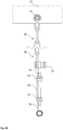
- Fig. 10 shows a train protection section 24 with a device for tensioning and fixing a certain length of the train protection section 24.
- the train securing section 24 consists of a chain which is connected to the base body 23 of the grid securing section 22 by a safety screw 50. At the other end, the chain is anchored in a wall of the light shaft (not shown), for example by means of a heavy-duty dowel (not shown).
- a long nut 68 is attached between this anchoring in a wall of the light shaft and the chain, an eyebolt 70 being screwed into both ends of the long nut 68.
- This eyebolt 70 is screwed to a tear-off nut 54 each in such a way that the tear-off nut 54 functions as a lock nut and fixes the eyebolt 70 relative to the long nut 68 so that it cannot rotate.
- the second eyebolt 70 is also fastened to the chain in the illustration by a shear nut 54.
- the long nut 68 including eye bolts 70 and shear nuts 54 can also be mounted between two chain sections.
Description
Die vorliegende Erfindung betrifft eine Befestigungsvorrichtung zum Sichern eines ersten Bauteils mit einer Gitterstruktur an einem zweiten Bauteil, insbesondere zum Sichern eines Gitterrostes in einem Lichtschacht nach dem Anspruch 1.The present invention relates to a fastening device for securing a first component with a lattice structure on a second component, in particular for securing a grating in a light shaft according to claim 1.
Gitterrost-Befestigungsvorrichtungen sind aus dem Stand der Technik bekannt und dienen vornehmlich, aber nicht nur zur Sicherung eines Gitterrostes in einem Lichtschacht, entgegen eines gewaltsamen Abnehmens des Gitterrostes durch unbefugte Personen. So ist daneben ein Einsatz zur Sicherung von Verschlägen, beispielsweise Kellerabteilgitter oder sonstigen Absperrgittern denkbar.Grating fastening devices are known from the prior art and are used primarily, but not only, to secure a grating in a light shaft, against the forcible removal of the grating by unauthorized persons. It is also conceivable to use it to secure crates, for example cellar compartment grids or other barriers.
Es ist bekannt, dass derartige Befestigungsvorrichtungen beispielsweise in Form von hakenförmigen oder mehrteiligen tellerartigen Konstruktionen aus einer Platte und einem Stab gebildet werden. So werden gattungsgemäße Befestigungsvorrichtungen derart ausgebildet, dass eine quadratische oder runde Platte auf die Gitterstruktur eines ersten Bauteils von oben aufgebracht wird und über eine Befestigungskonstruktion in Form einer Kette oder eines Metallbandes nach unten durch die Gitterstruktur hindurch an ein zweites Bauteil abgespannt wird.It is known that such fastening devices are formed, for example, in the form of hook-shaped or multi-part plate-like constructions from a plate and a rod. Fastening devices of the generic type are designed in such a way that a square or round plate is applied to the lattice structure of a first component from above and is clamped down through the lattice structure to a second component via a fastening structure in the form of a chain or a metal strip.
Gattungsgemäße Befestigungsvorrichtungen sind beispielsweise in der Gebrauchsmusterschrift
Eine weitere bekannte Möglichkeit ist eine Bauart als einfacher Haken, der an einem Stababschnitt der Gitterstruktur eingehängt wird und nach unten an ein zweites Bauteil angebracht und fixiert wird.Another known possibility is a design as a simple hook, which is hung on a rod section of the lattice structure and attached and fixed downwards to a second component.
Weiterhin offenbart die Gebrauchsmusterschrift GM 75 30 970 eine Haltevorrichtung für Abdeckgitterroste an Schächten oder dergleichen. Die Haltevorrichtung umgreift den Gitterrost hakenförmig durch eine in Hakenform ausgebildete Haltestange. Diese Haltestange ist mit einer Spannschraube zum Befestigen an beispielsweise Schachtwänden versehen. Um jegliche Betätigung der Spannschraube von der Gitteraußenseite her zu verhindern, ist der Schraubenkopf durch einen Flügel, bestehend aus einem Winkelstück, abgedeckt und somit gesichert. Um ein gewaltsames Aufbiegen des hakenförmigen Endes der Haltestange zu verhindern, können durch eine Verbindungsschraube die gegenüberliegenden Hakenschenkel miteinander fixiert werden.Furthermore, the utility model GM 75 30 970 discloses a holding device for grids on shafts or the like. The holding device engages around the grating in the shape of a hook by means of a holding rod designed in the form of a hook. This holding rod is provided with a clamping screw for fastening to, for example, shaft walls. In order to prevent any actuation of the clamping screw from the outside of the grille, the screw head is covered and thus secured by a wing consisting of an angle piece. In order to prevent the hook-shaped end of the holding rod from bending open by force, the opposing hook legs can be fixed to one another by a connecting screw.
In der schweizerischen Patentschrift
Die
Die Haltevorrichtung in der
In der
Die
Die
In der
Die
Die
Es besteht das Problem, dass einfache punktuelle Lagerungen von Befestigungsvorrichtungen, beispielsweise Sicherungseinheiten für Gitterroste wie in den bereits erwähnten Druckschriften, mit wenigen Handgriffen durch Durchtrennen einer geringeren Anzahl einzelner Stababschnitte der Gitterstruktur ohne viel Aufwand von unbefugten Personen gelöst werden können.There is the problem that simple selective storage of fastening devices, for example securing units for gratings as in the documents already mentioned, can be solved by unauthorized persons in a few simple steps by cutting through a smaller number of individual rod sections of the lattice structure.
Zudem besteht das Problem, dass bei punktförmiger Lagerung der Befestigungsvorrichtung an lediglich zwei Punkten der Gitterstruktur des Bauteils, dieses Bauteil durch unbefugte Personen aus seiner Ebene heraus verbogen oder gehebelt und um die hierdurch gebildete Drehachse verdreht werden kann, so dass unbefugte Personen durch den Lichtschacht bzw. das Kellerfenster in das Gebäude gelangen können.In addition, there is the problem that with point-like mounting of the fastening device at only two points of the lattice structure of the component, this component can be bent or levered out of its plane by unauthorized persons and rotated around the axis of rotation thus formed so that unauthorized persons can enter the building through the light shaft or the basement window.
Um eine Hebelmöglichkeit effektiv zu unterdrücken, wären mindestens vier Lagerpunkte und somit vier Befestigungsvorrichtungen notwendig, was einen erheblichen Montageaufwand erfordert. Zudem sind die tellerartigen Ausführungen, bestehend aus mindestens einer Platte und einem Haltestab sowie weiteren Fixierelementen und -profilen, mehrteilig ausgebildet, was die Herstellungskosten sowie den Montageaufwand erhöht und die Montage erschwert. Durch eine Vielzahl von Befestigungsvorrichtungen wird zudem der Lichteinfall durch die Gitterstruktur und somit in den Lichtschacht bzw. das Kellerfenster stark eingeschränkt.In order to effectively suppress the possibility of leverage, at least four bearing points and thus four fastening devices would be necessary, which requires considerable assembly effort. In addition, the plate-like designs, consisting of at least one plate and a holding rod as well as further fixing elements and profiles, are constructed in several parts, which increases the manufacturing costs and the assembly effort and makes assembly more difficult. A large number of fastening devices also restrict the incidence of light through the grid structure and thus into the light shaft or the basement window.
Ausgehend von dem oben genannten Stand der Technik ist es Aufgabe der Erfindung, die Nachteile der bekannten Anordnungen zu überwinden. Insbesondere ist es die Aufgabe der Erfindung, eine Befestigungsvorrichtung zu schaffen, mit welcher ein erstes Bauteil mit einer Gitterstruktur an einem zweiten Bauteil, das unterhalb des ersten Bauteils liegt, aufbruchssicher befestigt werden kann, wobei ein Aushebeln oder Verdrehen des ersten Bauteils erschwert bzw. unmöglich gemacht wird. Eine weitere Aufgabe hierbei ist es, den Lichteinfall durch die Gitterstruktur des ersten Bauteils in den Lichtschacht nicht unnötig einzuschränken.Starting from the above-mentioned prior art, the object of the invention is to overcome the disadvantages of the known arrangements. In particular, it is the object of the invention to create a fastening device with which a first component with a lattice structure can be fastened in a tamper-proof manner on a second component that is below the first component, making it difficult or impossible to lever out or twist the first component is made. Another task here is not to unnecessarily restrict the incidence of light into the light shaft through the lattice structure of the first component.
Ziel ist es weiterhin eine Befestigungseinrichtung zum Sichern eines Gitterostes oder ähnlichem bereitzustellen, wobei eine Sicherheit gegen das Eindringen unbefugter Personen mit einer Widerstandsklasse 3 oder höher nach DIN EN 1627 bzw. DIN V ENV 1627 in der Fassung des Jahres 2016 erreicht werden kann. Dies entspricht RC3 (DIN EN 1627) bzw. WK3 (DIN V ENV 127) in der Fassung des Jahres 2016.The aim is also to provide a fastening device for securing a grating or the like, whereby a security against the intrusion of unauthorized persons with a resistance class 3 or higher according to DIN EN 1627 or DIN V ENV 1627 in the version of the year 2016 can be achieved. This corresponds to RC3 (DIN EN 1627) or WK3 (DIN V ENV 127) in the version from 2016.
Die Aufgaben werden durch die Merkmale des unabhängigen Anspruchs gelöst.The tasks are solved by the features of the independent claim.
Günstige Ausgestaltungen und Vorteile der Erfindung ergeben sich aus den weiteren Ansprüchen, der Beschreibung und der Zeichnungen.Favorable configurations and advantages of the invention emerge from the further claims, the description and the drawings.
Es wird eine Befestigungsvorrichtung vorgeschlagen, zum Sichern eines ersten Bauteils mit einer Gitterstruktur, umfassend eine Mehrzahl von durch Stababschnitte begrenzten Maschen an einem zweiten Bauteil, wobei das erste Bauteil ein Gitterrost und das zweite Bauteil ein Lichtschacht ist, wobei die Befestigungsvorrichtung einen Gittersicherungsabschnitt zum Verbinden der Befestigungsvorrichtung mit der Gitterstruktur und einen Zugsicherungsabschnitt zum Verbinden der Befestigungsvorrichtung mit dem zweiten Bauteil umfasst, wobei der Gittersicherungsabschnitt einstückig oder mehrteilig ausgeformt ist.A fastening device is proposed for securing a first component with a lattice structure, comprising a plurality of meshes delimited by rod sections on a second component, the first component being a grating and the second component being a light shaft, the fastening device being a grid securing section for connecting the Fastening device with the lattice structure and a tension securing section for connecting the fastening device to the second component, wherein the lattice securing section is formed in one piece or in several parts.
Die Erfindung schlägt vor, dass der Gittersicherungsabschnitt mindestens drei bis zehn, insbesondere sieben oder acht Sicherungseinheiten aufweist, welche mit einem Grundkörper des Gittersicherungsabschnitts lösbar und / oder unlösbar verbunden sind, insbesondere angeschraubt, angenietet, angeschweißt oder angelötet sind und welche jeweils mit einem Stababschnitt der Gitterstruktur verbindbar sind wobei der Gittersicherungsabschnitt plattenförmig ausgebildet ist und die Sicherungseinheiten an einer Längskante des Gittersicherungsabschnitts derart ausgeformt und angebracht sind, dass sie kammartig mehrere Stababschnitte der Gitterstruktur umschließen können und jede Sicherungseinheit im Endbereich U-Hakenförmig ausgebildet ist und einen Stababschnitt des ersten Bauteils zumindest teilweise umfasst und lediglich die kammartige Sicherungseinheiten ohne flächige Bauteile von einer Position oberhalb des ersten Bauteils sichtbar sind, sodass ein Lichteinfall in die Gitterstruktur nicht eingeschränkt wird und optisch die Sicherungseinheiten kaum wahrgenommen werden, und wobei mindestens drei Stababschnitte der Gitterstruktur umschlossen werden.The invention proposes that the grid securing section has at least three to ten, in particular seven or eight securing units, which are detachably and / or non-detachably connected to a base body of the grid securing section, in particular screwed, riveted, welded or soldered and which are each connected to a rod section of the The lattice structure can be connected, the lattice securing section being plate-shaped and the securing units being shaped and attached to a longitudinal edge of the lattice securing section in such a way that they can enclose several rod sections of the lattice structure in a comb-like manner and each securing unit is U-hook-shaped in the end area and a rod section of the first component is at least partially and only the comb-like securing units without planar components are visible from a position above the first component, so that light does not enter the lattice structure is limited and optically the fuse units are barely perceived, and at least three rod sections of the lattice structure are enclosed.
Eine einteilige Ausführung des Gittersicherungsabschnittes ermöglicht eine einfache Montage und kostengünstige Herstellung der Befestigungsvorrichtung. Durch eine mehrteilige Ausführung des Gittersicherungsabschnitts kann eine erleichterte Montage sowie eine Skalierung und Anpassbarkeit der Gittersicherung erreicht werden. Durch eine streckenförmige Ausbildung, insbesondere eine linienförmige Ausbildung des Gittersicherungsabschnittes mit zumindest zwei entlang einer Strecke angeordneten Sicherungseinheiten, die mindestens drei Stababschnitte der Gitterstruktur be festigen, ist eine unbefugte Person gezwungen, eine hohe Anzahl von Stababschnitten der Gitterstruktur zu durchtrennen, um die Gitterstruktur aus der Befestigungsvorrichtung gewaltsam zu lösen. Es entsteht zusätzlich eine abschreckende Wirkung gegenüber einem möglichen Einbrecher. Zudem wird ein Verbiegen oder Aushebeln der Gitterstruktur des ersten Bauteils im eingebautem Zustand von wenigstens zwei Befestigungsvorrichtungen an zwei gegenüberliegenden Positionen des ersten Bauteils nahezu unmöglich, da durch eine linienförmige Lagerung jeder einzelnen Befestigungsvorrichtung die Gitterstruktur des ersten Bauteils gegen Verdrehen aus der Ebene sehr stark gesichert ist. Die Ausbildung des Gittersicherungsabschnitts kann bevorzugt geradlinig sein, allerdings sind auch gekrümmte oder gebogene Anordnungen der Sicherungseinheiten des Gittersicherungsabschnitts denkbar. So kann der Gittersicherungsabschnitt auch abgerundet ausgeformt sein, und die Form eines Rohrstückes aufweisen, oder der Gittersicherungsabschnitt kann abgewinkelt sein. Es sind auch geschlossene Ausbildungen des Gittersicherungsabschnitts in Form eines Zylinders, z.B. als Rohr- oder Rechteckzylinders denkbar, wobei die Oberkante des Gittersicherungsabschnitts eine Mehrzahl von Sicherungseinheiten aufweist, die zur Befestigung an Stababschnitten des ersten Bauteils dienen können. Die Sicherungseinheiten können lösbar und / oder unlösbar mit dem Grundkörper des Gittersicherungsabschnitts verbunden sein. Die Sicherungseinheiten können angeschraubt, angenietet, angeschweißt oder angelötet sein. Um die Demontage im eingebauten Zustand durch eine unbefugte Person zu verhindern können bei Montage der Sicherungsabschnitte Sicherheitsschrauben oder Bolzen bzw. Schrauben in Verbindung mit Abreißmuttern, Abreißschrauben oder ähnlichem verwendet werden. Sicherheitsschrauben besitzen hierfür einen speziellen Schraubenkopf mit speziellem Schraubenkopfantrieb, beispielsweise in Form einen Innen-Vielzahns oder eines Torx mit Stift oder Pin. Derartige Sicherheitsschrauben sind nur mit speziellem Werkzeug, Abreißmuttern oder -schrauben schwer bzw. nicht durch einfaches Abschrauben demontierbar.A one-piece design of the lattice securing section enables simple assembly and inexpensive manufacture of the fastening device. A multi-part design of the lattice securing section enables easier assembly, as well as scaling and adaptability of the lattice securing device. By means of a linear design, in particular a linear design of the lattice securing section with at least two securing units arranged along a path, which are at least three rod sections of the lattice structure consolidate, an unauthorized person is forced to cut through a large number of rod sections of the lattice structure in order to forcibly release the lattice structure from the fastening device. There is also a deterrent effect against a possible burglar. In addition, bending or levering out the lattice structure of the first component in the installed state of at least two fastening devices at two opposite positions of the first component is almost impossible, since the lattice structure of the first component is very strongly secured against twisting out of the plane through a linear mounting of each individual fastening device . The design of the grid securing section can preferably be straight, but curved or curved arrangements of the securing units of the grid securing section are also conceivable. Thus, the grid securing section can also have a rounded shape and have the shape of a pipe section, or the grid securing section can be angled. Closed designs of the lattice securing section in the form of a cylinder, for example as a tubular or rectangular cylinder, are also conceivable, the upper edge of the lattice securing section having a plurality of securing units which can be used for fastening to rod sections of the first component. The securing units can be detachably and / or non-detachably connected to the base body of the grid securing section. The fuse units can be screwed, riveted, welded or soldered on. In order to prevent dismantling by an unauthorized person in the installed state, safety screws or bolts or screws in conjunction with shear nuts, shear bolts or the like can be used when assembling the securing sections. For this purpose, safety screws have a special screw head with a special screw head drive, for example in the form of an internal multi-tooth or a Torx with a pin or pin. Such safety screws are difficult to dismantle or cannot be dismantled simply by unscrewing them using special tools, shear nuts or bolts.
Mit einer derartigen Ausgestaltung eines Gitterrostes kann eine Sicherheit gegen das Eindringen unbefugter Personen mit einer Widerstandsklasse 3 oder höher nach DIN EN 1627 bzw. DIN V ENV 1627 in der Fassung von 2016 erreicht werden. Dies entspricht RC3 (DIN EN 1627) bzw. WK3 (DIN V ENV 1627).With such a configuration of a grating, security against intrusion by unauthorized persons with a resistance class 3 or higher according to DIN EN 1627 or DIN V ENV 1627 in the version of 2016 can be achieved. This corresponds to RC3 (DIN EN 1627) or WK3 (DIN V ENV 1627).
Durch eine U-förmige, insbesondere hakenförmige Ausbildung, wird der jeweilige Stababschnitt sicher umfasst bzw. umgriffen und die Maschen der Gitterstruktur werden kaum abgedeckt, wodurch der Lichteinfall in die Gitterstruktur nicht eingeschränkt wird. Bevorzugt überlappen die Endbereiche der U-förmigen Sicherungseinheiten die Stababschnitte der Gitterstruktur um mindestens zusätzlich 5 mm, damit ein gewaltsames Aufbiegen der Endbereiche nicht mehr möglich ist. Zusätzlich können durch eine Verbindungsschraube die Endbereiche der U-förmigen Sicherungseinheiten mit den jeweils gegenüberliegenden Bereichen der jeweiligen Sicherungseinheit mit einer Schraube, einer Niete, einem Draht oder Seil fixiert werden, so dass die Stababschnitte rundum von der Sicherungseinheit umfasst sind.By means of a U-shaped, in particular hook-shaped design, the respective rod section is securely encompassed or encompassed and the meshes of the lattice structure are hardly covered, so that the incidence of light into the lattice structure is not restricted becomes. The end regions of the U-shaped securing units preferably overlap the rod sections of the lattice structure by at least an additional 5 mm so that the end regions can no longer be bent open by force. In addition, a connecting screw can be used to fix the end areas of the U-shaped securing units with the respective opposite areas of the respective securing unit with a screw, rivet, wire or rope, so that the rod sections are encompassed all around by the securing unit.
Durch die Ausbildung der drei bis zehn Sicherheitseinheiten kann eine kurze Längsseite eines ersten Bauteils, im Speziellen eines Gitterrostes, mit acht Sicherungseinheiten eine Gitterbreite von ca. 30 cm sehr gut sichern. Bei jeweils einer Befestigungsvorrichtung an jeder kurzen Längsseite des Gitterrostes müsste ein möglicher Einbrecher nahezu den gesamten Gitterrost in der Breite zweimal durchtrennen, wozu mindestens zwanzig Schnitte erforderlich wären. Die Anzahl der zu durchtrennenden Stababschnitte beim Entfernen der Gitterstruktur aus der montierten Befestigungseinrichtung beträgt zwei Mal der Anzahl der Sicherungseinheiten zuzüglich mindestens vier Stababschnitte im Randbereich.Due to the design of the three to ten safety units, a short long side of a first component, especially a grating, with eight safety units can secure a grating width of approx. 30 cm very well. With one fastening device on each short longitudinal side of the grating, a possible intruder would have to cut through almost the entire grating twice in width, which would require at least twenty cuts. The number of rod sections to be cut when removing the lattice structure from the mounted fastening device is twice the number of securing units plus at least four rod sections in the edge area.
Eine Gitterstruktur insbesondere eines Lichtschachtgitters umfasst mechanisch verstärkte Tragestäbe als Längsstäbe zur Aufnahme eines Tragegewichts und Querstäbe zur Verbindung der Tragestäbe. In der Regel ist die Höhe der Tragestäbe größer als die der Querstäbe, auch kann die Breite eines Tragstabes größer als die eines Querstabes sein. Bevorzugt wird die Befestigungseinrichtung bei Anbringung an einem Gitterrost in die weniger stabil ausgebildeten Querstäbe der Gitterstruktur eingehängt, sodass bei Entfernen der Befestigungsvorrichtung durch unbefugte Personen die stabileren, d.h. mit einer dickeren Wandstärke und durchgängig ausgebildeten Tragestäbe durchtrennt werden müssen.A lattice structure, in particular of a light shaft lattice, comprises mechanically reinforced support rods as longitudinal rods for receiving a support weight and transverse rods for connecting the support rods. As a rule, the height of the support rods is greater than that of the transverse rods, and the width of a support rod can also be greater than that of a transverse rod. When attached to a grating, the fastening device is preferably hooked into the less stable cross bars of the lattice structure, so that when the fastening device is removed by unauthorized persons, the more stable, i.e. have to be cut through with a thicker wall and continuously designed support rods.
Der Gittersicherungsabschnitt ist plattenförmig ausgebildet und die Sicherungseinheiten sind an einer Längskante des Gittersicherungsabschnitts derart ausgeformt und angebracht, dass sie kammartig mehrere Stababschnitte der Gitterstruktur umschließen können. Der Lichteinfall wird durch eine derart schlanke Ausführung der Sicherungseinheiten kaum eingeschränkt und optisch wird die Sicherungseinheit kaum wahrgenommen, da lediglich die kammartige Ausführung der Sicherungseinheiten ohne flächige Bauteile von einer Position oberhalb des ersten Bauteils sichtbar ist. Eine kammartige Ausführung der Sicherungseinheiten ermöglicht einen einfachen Herstellungsprozess aus nur einem Bauteil und eine einfache Montage einer linienförmigen Lagerung der Konstruktion in der Gitterstruktur ohne Vormontage einzelner Bauteile des Gittersicherungsabschnitts. Die Platte des Gittersicherungsabschnitts kann flach ausgeformt sein, und somit eine linienförmige Anordnung der Sicherungseinheiten definieren. Die Platte kann auch gekrümmt, abgewinkelt oder in sich geschlossen einen Zylinder ausformen, der z.B. rund oder rechteckig ausgeformt sein kann.The lattice securing section is plate-shaped and the securing units are shaped and attached to a longitudinal edge of the lattice securing section in such a way that they can enclose several rod sections of the lattice structure in a comb-like manner. The incidence of light is hardly restricted by such a slim design of the fuse units and the fuse unit is hardly noticeable optically, since only the comb-like design of the fuse units without flat components is visible from a position above the first component. A comb-like one Execution of the fuse units enables a simple manufacturing process from only one component and a simple assembly of a linear mounting of the construction in the lattice structure without pre-assembly of individual components of the lattice fuse section. The plate of the grid fuse section can be flat and thus define a linear arrangement of the fuse units. The plate can also be curved, angled or closed in itself to form a cylinder which, for example, can be round or rectangular.
In einer vorteilhaften Ausführungsform kann mindestens eine Sicherungseinheit, bevorzugt mindestens zwei Sicherungseinheiten, mit jeweils mindestens einer Sicherheitsschraube oder einer Schraube in Verbindung mit einer Abreißmutter oder einer Abreißschraube am Grundkörper des Gittersicherungsabschnitts befestigt sein. Sicherheitsschrauben sind mit Standardwerkzeug leicht zu montieren, können jedoch nach der Montage sehr schwer wieder entfernt werden. Bei Abreißmuttern bleibt nach der Montage eine konische Mutter zurück, die sich mit Standardwerkzeug nicht mehr demontieren lässt. Die Sicherung von Objekten gegen eine ungewollte Demontage ist mit diesen aufschraubbaren Abreißmuttern oder Abreißschrauben möglich. Nach dem Festziehen der Abreißmutter mittels eines an dem Kopf der Abreißmutter angreifenden Werkzeugs reißt bei fortgesetzter Krafteinwirkung mit diesem Werkzeug der Kopf ab, so dass lediglich noch der mit dem Werkzeug nicht mehr zugängliche Gewindeteil der Abreißmutter verbleibt und somit ein Lösen der Mutter mit einem Standardwerkzeug nicht mehr möglich ist. Die Sicherheitsschraube kann von einer beliebigen Seite, d.h. von der Seite des Grundkörpers des Gittersicherungsabschnitts oder von der Seite der Sicherungseinheiten, montiert werden. Von der dem Lichtschacht abgewandten Seite des Gitterrostes kann eine derartige Sicherheitsschraube nahezu unmöglich einhändig gelöst werden. Für eine zweihändige Demontage müsste eine unbefugte Person eine sehr große Aussparung in das Gitterrost einbringen, was einen hohen zeitlichen Aufwand mit sich zieht. Mindestens eine der Sicherheitsschrauben, Schrauben oder Bolzen kann gleichzeitig den Zugsicherungsabschnitt mit dem Grundkörper des Gittersicherungsabschnitts befestigen, wenn der Zugsicherungsabschnitt und der Gittersicherungsabschnitt aus mindestens zwei getrennten Bauteilen ausgebildet sind.In an advantageous embodiment, at least one securing unit, preferably at least two securing units, each with at least one safety screw or one screw in connection with a shear nut or shear screw can be attached to the base body of the lattice securing section. Safety screws are easy to assemble with standard tools, but are very difficult to remove after assembly. With shear nuts, a conical nut remains after assembly, which can no longer be dismantled with standard tools. Securing objects against unintentional dismantling is possible with these screw-on shear nuts or shear bolts. After the breakaway nut has been tightened by means of a tool that engages the head of the breakaway nut, the head tears off when the force continues with this tool, so that only the threaded part of the breakaway nut that is no longer accessible with the tool remains and thus the nut cannot be loosened with a standard tool more is possible. The safety screw can be mounted from any side, ie from the side of the base body of the grid securing section or from the side of the securing units. From the side of the grating facing away from the light shaft, it is almost impossible to loosen such a safety screw with one hand. For a two-handed dismantling, an unauthorized person would have to make a very large recess in the grating, which involves a lot of time. At least one of the safety screws, screws or bolts can simultaneously fasten the tension protection section to the base body of the grid protection section if the tension protection section and the grid protection section are formed from at least two separate components.
In einer vorteilhaften Ausführungsform können der Gittersicherungsabschnitt und der Zugsicherungsabschnitt aus getrennten Bauteilen ausgebildet werden. Dadurch ist eine flexible Ausgestaltung des Zugsicherungsabschnitts möglich. Der Zugsicherungsabschnitt kann ein- oder mehrteilig ausgebildet sein und an verschiedene Geometrien der Randbereiche des Lichtschachtes angepasst werden. Zudem kann der Zugsicherungsabschnitt flexibel ausgetauscht werden. Mehrere Gittersicherungseinheiten können somit auch mit einem gemeinsamen Zugsicherungsabschnitt gesichert werden.In an advantageous embodiment, the grid securing section and the train securing section can be formed from separate components. This enables a flexible design of the train protection section. The train protection section can be designed in one or more parts and can be adapted to different geometries of the edge areas of the light shaft. In addition, the train protection section can be exchanged flexibly. Several grid protection units can thus also be secured with a common train protection section.
In einer vorteilhaften Ausführungsform können der Gittersicherungsabschnitt und der mindestens eine Zugsicherungsabschnitt durch eine kraftschlüssige und nicht werkzeugfrei lösbare Verbindung, insbesondere eine Schrauben- oder Nietverbindung, miteinander verbunden werden. Durch die zweigeteilte Ausführung des Gittersicherungsabschnitts und des Zugsicherungsabschnitts ist eine flexible Ausgestaltung beider Abschnitte möglich. Zusätzlich kann der Schrauben- oder Nietenkopf durch einen Flügel, bestehend beispielsweise aus einem Winkelstück, abgedeckt und somit entgegen einer Demontage von einer unbefugten Position oberhalb der Gitterstruktur gesichert werden.In an advantageous embodiment, the grid securing section and the at least one tension securing section can be connected to one another by a force-fit connection that cannot be released without tools, in particular a screw or rivet connection. The two-part design of the lattice securing section and the tension securing section enables a flexible design of both sections. In addition, the screw or rivet head can be covered by a wing, consisting for example of an angle piece, and thus secured against dismantling from an unauthorized position above the lattice structure.
Alternativ können der Gittersicherungsabschnitt und der Zugsicherungsabschnitt mittels einer flexiblen Ketten- oder Seilverbindung miteinander verbunden sein, was insbesondere die Möglichkeit eröffnet, dass mehrere Gittersicherungsabschnitte mit einem Zugsicherungsabschnitt verbunden werden. Hierbei bietet es sich bevorzugt an, dass der Gittersicherungsabschnitt mindestens eine in Hakenform ausgebildete Ausnehmung aufweist, in welche der mindestens eine Zugsicherungsabschnitt eingehängt werden kann, oder mit dem der Zugsicherungsabschnitt mit dem Gittersicherungsabschnitt befestigt werden kann. Hierdurch kann werkzeugfrei und einfach eine zugesicherte Befestigung des Gittersicherungsabschnitts erreicht werden.Alternatively, the grid securing section and the train securing section can be connected to one another by means of a flexible chain or rope connection, which in particular opens up the possibility of several grid securing sections being connected to one train securing section. It is preferable here that the lattice securing section has at least one recess in the form of a hook, into which the at least one tension securing section can be hooked or with which the tension securing section can be attached to the lattice securing section. As a result, an assured fastening of the grid securing section can be achieved simply and without tools.
In einer vorteilhaften Ausführungsform kann der Zugsicherungsabschnitt aus einem stabartigen, seilartigen, profilartigen oder kettenartigen Bauteil gebildet werden. Dadurch kann der Zugsicherungsabschnitt flexibel an unterschiedliche Geometrieformen des zweiten Bauteils angepasst werden, und beispielsweise mittels einer Dübelverbindung, Bolzenverbindung oder einer Ankerverbindung an diesem zweiten Bauteil befestigt werden. Zudem kann der Zugsicherungsabschnitt flexibel ausgetauscht oder nachgespannt werden.In an advantageous embodiment, the tension protection section can be formed from a rod-like, rope-like, profile-like or chain-like component. As a result, the tension protection section can be flexibly adapted to different geometrical shapes of the second component and can be attached to this second component, for example by means of a dowel connection, bolt connection or an anchor connection. In addition, the train protection section can be flexibly exchanged or retensioned.
In einer vorteilhaften Ausführungsform kann der Zugsicherungsabschnitt über mindestens eine Langmutter sowie mindestens eine Augenschraube in einer Länge einstellbar und fixierbar sein. Dies ist besonders bei einer Ausführung des Zugsicherungsabschnitts als kettenartiges Bauteil von Vorteil, da dieses besonders gut vorgespannt bzw. gespannt werden kann. Zwischen einem Ende des Zugsicherungsabschnitts und einem zweiten Bauteil, beispielsweise der Wand eines Lichtschachtes, kann eine Langmutter mit mindestens einer Augenschaube montiert werden, um den Zugsicherungsabschnitt in der Länge variabel einzustellen und in einer gewünschten Länge zu fixieren. Bevorzugt ist an jeder Seite der Langmutter eine Augenschraube montiert, wobei an der einen Augenschraube das kettenartige Bauteil eingehängt werden kann und an der anderen Augenschraube die Befestigung an einem zweiten Bauteil erfolgen kann. Durch Drehen mindestens einer Augenschraube entgegen der Langmutter kann der Zugsicherungsabschnitt vorgespannt und in einer gewünschten Länge fixiert werden. Die Befestigung an einem zweiten Bauteil, wie der Wand eines Lichtschachts, kann über einen Schwerlastdübel, beispielsweise einen Bolzenanker oder eine Stockschraube, erfolgen. An beiden Enden der Langmutter kann eine Abreißmutter montiert werden und als Kontermutter fungieren. So kann die Langmutter nicht gegen die Augenschrauben verdreht werden und demnach nur schwer von unbefugten Personen demontiert werden.In an advantageous embodiment, the tension protection section can be adjustable and fixable in length via at least one long nut and at least one eyebolt. This is particularly advantageous when the tension protection section is designed as a chain-like component, since it can be pretensioned or tensioned particularly well. A long nut with at least one eyelet can be mounted between one end of the tension protection section and a second component, for example the wall of a light shaft, in order to adjust the length of the tension protection section variably and to fix it in a desired length. An eyebolt is preferably mounted on each side of the long nut, with the chain-like component being able to be hooked into one eyebolt and attachment to a second component being possible on the other eyebolt. By turning at least one eyebolt against the long nut, the tension protection section can be pretensioned and fixed in a desired length. The attachment to a second component, such as the wall of a light shaft, can be carried out using a heavy-duty dowel, for example a bolt anchor or a hanger bolt. A shear nut can be fitted to both ends of the long nut and act as a lock nut. The long nut cannot be twisted against the eye bolts and can therefore only be dismantled with difficulty by unauthorized persons.
In einer vorteilhaften Ausführungsform kann der Zugsicherungsabschnitt mit mindestens einem Schwerlastdübel, insbesondere einem Bolzenanker oder einer Stockschraube, mit oder ohne Splintloch zur Durchführung einer Spannhülse oder eines Splints oder Federsplints, an einer Wand des Lichtschachts befestigt sein. Durch Schwerlastdübel, wie Bolzenanker, Porenbetonanker, Nagelanker, Schwerlastanker, Einschlaganker oder ähnlichem, kann der Zugsicherungsabschnitt demontagesicher an einem zweiten Bauteil, wie der Wand eines Lichtschachts, montiert werden. Dies bietet sich besonders bei einer Betonbauweise des Lichtschachtes an. Der Bolzenanker besitzt ein Gewinde sowie eine Mutter. Der Bolzenanker wird in ein vorgebohrtes Bohrloch einschlagen, wobei ein Spreizclip durch Eigenspannung an der Bohrlochwandung anliegt. Beim Anziehen der Mutter zieht sich ein Konus in den Spreizclip, spreizt diesen und verpresst ihn gegen den umgebenden Beton. Am mutterseitigen Ende des Gewindebolzens kann ein Loch zur Durchführung eines Splints oder einer Spannhülse angebracht sein. Splinte werden beispielsweise aus Draht mit halbrundem Querschnitt gefertigt. Die beiden Schenkel unterschiedlicher Länge sind parallel aufeinander gepresst und bilden einen runden Querschnitt mit in der Norm festgelegtem Durchmesser. An einem Ende ist der Draht zu einer annähernd kreisringförmigem Schlaufe, dem Splintkopf mit ebenfalls genormten Maßen, gestaucht. Die Schenkel können nach dem Durchstecken gegeneinander aufgebogen. Bei Einsatz einer Spannhülse wird ein längsgeschlitzter, hülsenförmiger Stift in das Splintloch eingepresst, wobei die Spannhülse an mindestens einer Seite über den Durchmesser des Schwerlastdübels überstehen muss. Durch die längsgeschlitzte Bauform weitet sich die Spannhülse im eingebauten Zustand auf und verpresst sich gegen das Splintloch. Eine Demontage ist ebenso nur mit einem Spezialwerkzeug, insbesondere einem Splinttreiber, möglich, wobei dies kaum einhändig möglich ist. Nach Montage des Bolzenankers und Einbringung eines Splints oder einer Spannhülse kann die Mutter nicht ohne Entfernen des Splints gelöst werden. Der Splint kann nur mithilfe eines Splinttreibers entfernt werden. Dieser ist nur zweihändig bedienbar. Somit ist auch der Bolzenanker nur zweihändig lösbar. Bei einer Bauweise des Lichtschachts aus beispielsweise Mauerwerk, können ebenso Stockschrauben mit oder ohne Splintloch oder ähnliches zur sicheren Montage verwendet werden. Die Stockschraube besitzt bevorzugt an den beiden Enden zwei gegenläufige Gewinde. Für eine unbefugte Person von der vom Lichtschacht abgewandten Seite des Gitterrostes müsste demnach eine Öffnung in der Größe in das Gitterrost eingebracht werden, dass beide Hände durchführbar wären. Dies würde eine enorme Zeit in Anspruch nehmen, was eine erhöhte Widerstandzeit nach den normierten Widerstandsklassen mit sich zieht. Eine Einordnung einer derart gesicherten Befestigungsvorrichtung für Gitterroste kann in die Widerstandsklasse RC3 (nach DIN EN 1627) bzw. WK3 (nach DIN V ENV 1627) oder höher ohne weiteres erfolgen. Eine schnelle Entriegelung von Innen ist jederzeit gegeben, da eine zweihändige Montage / Demontage von der Seite des Lichtschachts, zum Beispiel durch das Kellerfenster, ohne weiteres möglich ist.In an advantageous embodiment, the tension securing section can be attached to a wall of the light shaft with at least one heavy-duty dowel, in particular a bolt anchor or a hanger bolt, with or without a split pin hole for the implementation of a clamping sleeve or a split pin or spring split pin. Using heavy-duty anchors, such as bolt anchors, aerated concrete anchors, nail anchors, heavy-duty anchors, drop-in anchors or the like, the tension protection section can be mounted on a second component, such as the wall of a light shaft, in a safe manner. This is particularly suitable for a concrete light shaft construction. The bolt anchor has a thread and a nut. The bolt anchor is hammered into a pre-drilled borehole, with an expansion clip resting against the borehole wall due to internal stress. When the nut is tightened, a cone pulls itself into the expansion clip, expands it and presses it against the surrounding concrete. At the end of the threaded bolt on the nut side, a hole for the passage of a split pin or a clamping sleeve can be made. For example, split pins are made from wire with a semicircular cross-section. The two legs of different lengths are pressed parallel to one another and form a round cross-section with a diameter specified in the standard. At one end, the wire is compressed to form an approximately circular loop, the split pin head, which also has standardized dimensions. The legs can be bent up against each other after being pushed through. When using a clamping sleeve, a longitudinally slotted, sleeve-shaped pin is pressed into the split pin hole, whereby the clamping sleeve must protrude beyond the diameter of the heavy-duty dowel on at least one side. Due to the longitudinally slotted design, the clamping sleeve expands when installed and presses against the split pin hole. Disassembly is also only possible with a special tool, in particular a pin punch, although this is hardly possible with one hand. After installing the bolt anchor and inserting a split pin or an adapter sleeve, the nut cannot be loosened without removing the split pin. The cotter pin can only be removed with a pin punch. This can only be operated with two hands. Thus the bolt anchor can only be released with two hands. If the light shaft is constructed from masonry, for example, hanger bolts with or without a split pin hole or the like can also be used for secure assembly. The hanger bolt preferably has two threads running in opposite directions at the two ends. For an unauthorized person from the side of the grating facing away from the light shaft, an opening of the size would have to be made in the grating so that both hands could be passed through. This would take an enormous amount of time, which means an increased resistance time according to the standardized resistance classes. Such a secured fastening device for gratings can easily be classified in resistance class RC3 (according to DIN EN 1627) or WK3 (according to DIN V ENV 1627) or higher. A quick release from the inside is always possible, as two-handed assembly / disassembly from the side of the light shaft, for example through the basement window, is easily possible.
In einer vorteilhaften Ausführungsform kann der Zugsicherungsabschnitt mit mindestens einem Schwerlastdübel wie einem Bolzenanker oder einer Stockschraube mit oder ohne Bohrung zur Durchführung eines Vorhängeschlosses an einer Wand des Lichtschachts befestigt sein.In an advantageous embodiment, the tension protection section can be fastened to a wall of the light shaft with at least one heavy-duty dowel such as a bolt anchor or a hanger bolt with or without a hole for the implementation of a padlock.
In einer vorteilhaften Ausführungsform kann ein Verbindungsbereich der Sicherungseinheit eine Länge eines Stababschnittes b der Gitterstruktur des ersten Bauteils entsprechen. Dadurch können die Sicherungseinheiten passgenau in die Maschen der Gitterstruktur eingehängt werden. Die Breite b eines Stababschnittes der Gitterstruktur kann beispielsweise aus der Norm DIN 24 537, Stand Oktober 1991 entnommen werden, in welcher die Maße, Bezeichnungen und die Belastung von Gitterrosten geregelt ist. Wenn die Sicherungseinheiten passgenau an die Breite b eines Stababschnittes angepasst werden, können die Stababschnitte, welche von den Sicherungseinheiten umfasst sind, nur sehr mühevoll und aufwändig gewaltsam durch Bolzenschneider oder ähnliches getrennt werden. Zudem ist ein Verschieben der Gitterstruktur quer zur Befestigungsvorrichtung durch derartige Sicherungseinheiten nicht möglich.In an advantageous embodiment, a connection area of the securing unit can correspond to a length of a rod section b of the lattice structure of the first component. This allows the fuse units to be hooked into the mesh of the lattice structure with a precise fit. The width b of a rod section of the lattice structure can, for example, be taken from the
In einer vorteilhaften Ausführungsform kann der Verbindungsbereich der Sicherungseinheit eine Breite b von 25 mm bis 35 mm, bevorzugt 28 mm und einen Abstand d von 3 mm bis 6 mm, bevorzugt 4,5 mm zum Verbindungsbereich einer benachbarten Sicherungseinheit aufweisen. Die Sicherungseinheiten können so an die normgerechten Vorgaben für die Abmessungen von Gitterrosten angepasst werden und können für eine Vielzahl kommerziell erhältlicher Gitterroste eingesetzt werden. Durch die vorgenannten Abmessungen verbleibt innerhalb eines Stababschnittes kein Raum zum Ansetzen eines Bolzenschneiders oder ähnlichem werkstofftrennenden Werkzeug. Ein Verschieben des ersten Bauteils, beispielsweise des Gitterrostes, relativ zur Sicherungseinheit ist somit nicht mehr möglich. Bei unsymmetrisch ausgebildeten Gitterstrukturen mit einer Gitterkantenlänge von z.B. 3:1 kann die Sicherungseinheit eine Breite von 6 mm bis 9 mm, bevorzugt 7,5 mm aufweisen, um Querstäbe der Gitterstruktur umfassen zu können. Die Sicherungseinheit kann dann in die kurzen Querstäbe der Gitterstruktur eingehängt werden.In an advantageous embodiment, the connection area of the fuse unit can have a width b of 25 mm to 35 mm, preferably 28 mm and a distance d of 3 mm to 6 mm, preferably 4.5 mm to the connection area of an adjacent fuse unit. The fuse units can be adapted to the standard specifications for the dimensions of gratings and can be used for a large number of commercially available gratings. Due to the aforementioned dimensions, there is no space left within a rod section for attaching a bolt cutter or similar material-separating tool. Moving the first component, for example the grating, relative to the securing unit is no longer possible. In the case of asymmetrically designed lattice structures with a lattice edge length of, for example, 3: 1, the security unit can have a width of 6 mm to 9 mm, preferably 7.5 mm To include cross bars of the lattice structure. The securing unit can then be hooked into the short cross bars of the lattice structure.
In einer vorteilhaften Ausführungsform kann der Gittersicherungsabschnitt aus einem Metallblech, insbesondere aus einem verzinkten Stahlblech gebildet werden, wobei bei einstückiger Ausführung des Gittersicherungsabschnitts die Sicherungseinheiten durch Einschneiden von Blechzungen an einer Längskante des Metallblechs und Biegeverformen von Endabschnitten der Blechzungen ausgebildet sind. Im Herstellungsprozess werden in das Metallblech, welches eine Dicke von 3 mm aufweisen kann, an einer Längskante einzelne Blechzungen beispielsweise eingefräst, gestanzt, gelasert oder eingeschnitten. Diese Blechzungen werden an ihren Endabschnitten gebogen und so zu hakenförmigen Sicherungseinheiten ausgebildet. Die Endabschnitte können hierbei parallel zu den Blechzungen ausgebildet werden. Eine Verzinkung erhöht die Wetterbeständigkeit und schützt vor Korrosion. Vorzugsweise wird der Gittersicherungsabschnitt gehärtet, um die Zähigkeit und Härte der Befestigungsvorrichtung zu erhöhen. Ein derartiges Herstellungsverfahren ist kostengünstig und mit wenig Aufwand verbunden. Der Gittersicherungsabschnitt besteht lediglich aus einem Bauteil und kann mit wenigen Arbeitsschritten hergestellt werden.In an advantageous embodiment, the grid securing section can be formed from a metal sheet, in particular from a galvanized steel sheet, with the securing units being formed by cutting sheet metal tongues on a longitudinal edge of the metal sheet and bending end sections of the sheet metal tongues in the one-piece design of the grid securing section. In the manufacturing process, individual sheet metal tongues are, for example, milled, punched, lasered or cut into the sheet metal, which can have a thickness of 3 mm, on a longitudinal edge. These sheet metal tongues are bent at their end sections and thus formed into hook-shaped securing units. The end sections can be formed parallel to the sheet metal tongues. Galvanizing increases the weather resistance and protects against corrosion. Preferably, the grid securing portion is hardened to increase the toughness and hardness of the fastening device. Such a production method is inexpensive and involves little effort. The grid securing section consists of only one component and can be produced in just a few steps.
In einer vorteilhaften Ausführungsform können die Sicherungseinheiten um einen Winkel α > 0°, insbesondere um einen Winkel α = 45° oder α = 90°, gegenüber einer plattenförmigen Erstreckung des Gittersicherungsabschnitts verdreht ausgebildet sein. Durch die Möglichkeit, die Sicherungseinheiten in einem beliebigen Winkel gedreht anzuordnen, können entweder Längs- oder Querstababschnitte der Gitterstruktur oder beide in Kombination von den Sicherungseinheiten erfasst werden. Es können beispielsweise nur die beiden äußeren Sicherungseinheiten um α = 90° gedreht angeordnet werden, während die Sicherungseinheiten im mittleren Bereich des Gittersicherungsabschnitts in der Position α = 0° verbleiben. Ebenso können alle Sicherungseinheiten einer Gittersicherungseinheit um den gleichen Winkel α gedreht angeordnet werden. Die Befestigungsvorrichtung kann somit beispielsweise auch diagonal in eine rechteckige Gitterstruktur eines ersten Bauteils angebracht werden, sofern der Gittersicherungsabschnitt geradlinig ausgeformt ist. Bei gekrümmten oder abgewinkelten Verlauf des Gittersicherungsabschnitts dient die Abwinkelung der Sicherungseinheiten der Anpassung an die fixierte Lage der Stababschnitte. Im Fall eines Lichtschachtes mit einem Gitterrost kann somit nur eine Befestigungsvorrichtung zur Sicherung des Gitterrostes ausreichend sein. Ebenso kann der Gittersicherungsabschnitt im Ganzen mit einem Winkel versehen sein, mit anderen Worten einen Knick aufweisen und beispielsweise für eine Anordnung der Befestigungsvorrichtung über Eck vorgesehen sein. Die Befestigungsvorrichtung kann somit optimal an die Geometrie des Gittersicherungsabschnitts angepasst werden. Mit dieser Ausführung können mehrere zusammenhängende Längsstababschnitte in Kombination mit mehreren zusammenhängenden Querstababschnitten mit den Sicherungseinheiten umfasst werden. Ein rechteckiger Gitterrost kann mit dieser Ausführung an zwei diagonal gegenüberliegenden Ecken gesichert werden.In an advantageous embodiment, the securing units can be designed rotated by an angle α> 0 °, in particular by an angle α = 45 ° or α = 90 °, with respect to a plate-shaped extension of the grid securing section. Due to the possibility of arranging the securing units rotated at any desired angle, either longitudinal or transverse bar sections of the lattice structure or both in combination can be detected by the securing units. For example, only the two outer securing units can be arranged rotated by α = 90 °, while the securing units in the middle area of the grid securing section remain in the position α = 0 °. Likewise, all fuse units of a grid fuse unit can be arranged rotated by the same angle α. The fastening device can thus, for example, also be attached diagonally in a rectangular lattice structure of a first component, provided that the lattice securing section is shaped in a straight line. In the case of a curved or angled course of the grid securing section, the angling of the securing units is used the adaptation to the fixed position of the rod sections. In the case of a light shaft with a grating, only one fastening device can thus be sufficient to secure the grating. Likewise, the grid securing section can be provided as a whole with an angle, in other words have a kink and, for example, be provided for an arrangement of the fastening device at a corner. The fastening device can thus be optimally adapted to the geometry of the grid securing section. With this embodiment, several contiguous longitudinal bar sections in combination with several contiguous transverse bar sections can be comprised with the securing units. With this version, a rectangular grating can be secured at two diagonally opposite corners.
In einer vorteilhaften Ausführungsform kann zumindest eine Sicherungseinheit nach Verbindung an einem Stababschnitt, bevorzugt Einhängen in einen Stababschnitt mittels eines Sicherungsbolzens oder einer Sicherheitsschraube oder einer Schraube in Verbindung mit einer Abreißmutter oder einer Abreißschraube an den Stababschnitt, gegen ein Ablösen, insbesondere gegen ein Aushängen, gesichert werden. Ein gewaltsames Aufbiegen der Sicherungseinheiten kann somit verhindert werden, da die Sicherungseinheit den Stababschnitt vollständig umschließt und ohne vorheriger Öffnung der Verschraubung oder Entfernen des Bolzens ein Aushängen des Gittersicherungsabschnitts nicht möglich ist.In an advantageous embodiment, at least one securing unit after connection to a rod section, preferably hanging in a rod section, can be secured against detachment, in particular against unhinging, by means of a securing bolt or a safety screw or a screw in connection with a shear nut or shear screw on the rod section will. Forcible bending of the securing units can thus be prevented, since the securing unit completely encloses the rod section and the grid securing section cannot be unhooked without first opening the screw connection or removing the bolt.
Weitere Vorteile ergeben sich aus der folgenden Zeichnungsbeschreibung. In den Zeichnungen sind Ausführungsbeispiele der Erfindung dargestellt. Die Zeichnungen, die Beschreibung und die Ansprüche enthalten zahlreiche Merkmale in Kombination. Der Fachmann wird die Merkmale zweckmäßigerweise auch einzeln betrachten und zu sinnvollen weiteren Kombinationen zusammenfassen ohne dabei vom Umfang der nachstehenden Ansprüche abzuweichen.Further advantages emerge from the following description of the drawings. Exemplary embodiments of the invention are shown in the drawings. The drawings, the description and the claims contain numerous features in combination. The person skilled in the art will expediently also consider the features individually and combine them into meaningful further combinations without deviating from the scope of the following claims.
Im Einzelnen zeigen die Zeichnungen:
- Fig. 1a:
- eine Seitenansicht einer erfindungsgemäßen Befestigungsvorrichtung mit U-förmigen Sicherungseinheiten, welche kammartig angeordnet sind,
- Fig. 1b:
- eine Längsschnittdarstellung einer erfindungsgemäßen Befestigungsvorrichtung mit U-förmigen Sicherungseinheiten, welche kammartig angeordnet sind,
- Fig. 1c:
- eine Querschnittsdarstellung einer erfindungsgemäßen Befestigungsvorrichtung mit U-förmigen Sicherungseinheiten, welche kammartig angeordnet sind,
- Fig. 2:
- eine isometrische Darstellung einer erfindungsgemäßen Befestigungsvorrichtung mit U-förmigen Sicherungseinheiten, welche kammartig angeordnet sind,
- Fig. 3:
- eine erfindungsgemäße Befestigungsvorrichtung mit U-förmigen Sicherungseinheiten, welche kammartig angeordnet sind, angebracht an einen Gitterrost,
- Fig. 4:
- eine weitere Ausführungsform der Erfindung mit um einen Winkel α gedreht angeordneten Sicherungseinheiten,
- Fig. 5:
- eine weitere Ausführungsform der Erfindung mit Gittersicherungsabschnitt und Zusicherungsabschnitt als einteilig ausgebildete Konstruktion,
- Fig. 6a:
- eine Seitenansicht einer erfindungsgemäßen Befestigungsvorrichtung mit U-förmigen Sicherungseinheiten, welche lösbar mit dem Grundkörper des Gittersicherungsabschnitts verbunden sind,
- Fig. 6b:
- eine Querschnittsdarstellung einer erfindungsgemäßen Befestigungsvorrichtung mit U-förmigen Sicherungseinheiten, welche lösbar mit dem Grundkörper des Gittersicherungsabschnitts verbunden sind,
- Fig. 7:
- eine isometrische Darstellung einer erfindungsgemäßen Befestigungsvorrichtung mit U-förmigen Sicherungseinheiten, welche lösbar mit dem Grundkörper des Gittersicherungsabschnitts verbunden sind,
- Fig. 8a:
- Sicherungseinheit des Gittersicherungsabschnitts,
- Fig. 8b:
- Grundelement des Gittersicherungsabschnitts,
- Fig. 9a-c:
- Bolzenanker in drei Ansichten,
- Fig. 10:
- Zugsicherungsabschnitt mit Langmutter und Augenschrauben.
- Fig. 1a:
- a side view of a fastening device according to the invention with U-shaped fuse units, which are arranged like a comb,
- Fig. 1b:
- a longitudinal sectional view of a fastening device according to the invention with U-shaped securing units which are arranged in a comb-like manner,
- Fig. 1c:
- a cross-sectional view of a fastening device according to the invention with U-shaped fuse units, which are arranged in a comb-like manner,
- Fig. 2:
- an isometric view of a fastening device according to the invention with U-shaped securing units which are arranged like a comb,
- Fig. 3:
- a fastening device according to the invention with U-shaped fuse units, which are arranged in a comb-like manner, attached to a grating,
- Fig. 4:
- a further embodiment of the invention with fuse units rotated by an angle α,
- Fig. 5:
- a further embodiment of the invention with a grid securing section and securing section as a one-piece construction,
- Fig. 6a:
- a side view of a fastening device according to the invention with U-shaped fuse units, which are detachably connected to the base body of the lattice fuse section,
- Fig. 6b:
- a cross-sectional view of a fastening device according to the invention with U-shaped securing units, which are detachably connected to the base body of the lattice securing section,
- Fig. 7:
- an isometric view of a fastening device according to the invention with U-shaped securing units, which are detachably connected to the base body of the lattice securing section,
- Fig. 8a:
- Fuse unit of the grid fuse section,
- Fig. 8b:
- Basic element of the grid securing section,
- Fig. 9a-c:
- Bolt anchor in three views,
- Fig. 10:
- Train protection section with long nut and eye bolts.
In den Figuren sind gleiche oder gleichartige Komponenten mit gleichen Bezugszeichen beziffert. Die Figuren zeigen lediglich Beispiele und sind nicht beschränkend zu verstehen.Identical or similar components are numbered with the same reference symbols in the figures. The figures show only examples and are not to be understood as restrictive.
Der Gittersicherungsabschnitt 22 kann aus einem Metallblech 40, insbesondere aus einem verzinkten Stahlblech, gebildet sein. Der Gittersicherungsabschnitt 22 und der Zugsicherungsabschnitt 24 sind durch eine lösbare Verbindung 28 miteinander verbunden. Diese lösbare Verbindung 28 kann beispielsweise in Form einer Schrauben- oder Nietverbindung 38, beispielsweise mit Sicherheitsschrauben, ausgebildet sein. Der Zugsicherungsabschnitt kann beispielsweise durch ein stabartiges, seilartiges, profilartiges oder kettenartiges Bauteil gebildet werden. Der Zugsicherungsabschnitt 24 kann im Endbereich 46 mit einem zweiten Bauteil verbunden werden. Hierbei kann der Zugsicherungsabschnitt 24 einteilig oder auch mehrteilig ausgebildet werden.The
In
Der Zugsicherungsabschnitt 24 kann in seinem Endbereich 46 an dem zweiten Bauteil 18 über Bolzenanker (nicht dargestellt) fixiert werden. Zur Sicherung eines Lichtschachtes 11 können zwei Befestigungsvorrichtungen 20 an zwei gegenüberliegenden Schachtwänden des Lichtschachtes 11 angebracht werden. Hierbei kann die Anzahl der Sicherungseinheiten 26 an die Anzahl der Maschen 14 der Gitterstruktur 12 des ersten Bauteils 10 angepasst werden. Eine Breite der Gitterstruktur 12 von ca. 30 cm kann mit zwei Befestigungseinrichtungen 20 mit jeweils acht Sicherungseinheiten 26 mit einer Breite b von jeweils 29 mm ausreichend gesichert werden. Die Anzahl der zu durchtrennenden Stababschnitte 16 bei unbefugtem entfernen der Gitterstruktur 12 aus der Befestigungseinrichtung 20 beträgt: Anzahl der Sicherungseinheiten x 2 + 4. Bei acht Sicherungseinheiten je Befestigungsvorrichtung müssten insgesamt 20 Stababschnitte der Gitterstruktur durchtrennt werden. An einer bodenseitigen Unterkante des Gittersicherungsabschnitts 22 sind zwei spiegelbildlich zueinander angeordnete hakenförmige Ausnehmungen 48 vorgesehen, in denen beispielsweise ein oder zwei Zugsicherungsketten oder Zugsicherungsseile eingehängt werden können, um den Gittersicherungsabschnitt zu befestigen. Die Befestigungshaken 48 können zusätzlich oder alternativ zu den dargestellten Zugsicherungsabschnitten 24, die in Form von Flachstangen oder Flachverbinder ausgebildet sind, zur Zugsicherung des Gittersicherungsabschnitts 22 eingesetzt werden.The
In
In
In den
In
- 1010
- erstes Bauteilsfirst component
- 1111
- LichtschachtLight shaft
- 1212
- GitterstrukturLattice structure
- 1414th
- Maschemesh
- 1616
- StababschnittRod section
- 1717th
- Rahmen der GitterstrukturFrame of the lattice structure
- 1818th
- zweites Bauteilsecond component
- 1919th
- AuflagerkanteSupport edge
- 2020th
- BefestigungsvorrichtungFastening device
- 2222nd
- GittersicherungsabschnittGrid fuse section
- 2323
- Grundkörper des GittersicherungsabschnittsBasic body of the grid fuse section
- 2424
- ZugsicherungsabschnittTrain protection section
- 2626th
- SicherungseinheitFuse unit
- 2828
- lösbare VerbindungDetachable connection
- 3030th
- Endbereich der SicherungseinheitEnd of the fuse unit
- 3232
- hakenförmige Sicherungseinheithook-shaped fuse unit
- 3434
- Längskante der SicherungseinheitLong edge of the fuse unit
- 3636
- Verbindungsbereich der SicherungseinheitConnection area of the fuse unit
- 3838
- Schrauben- oder NietenverbindungScrew or rivet connection
- 4040
- Metallblechmetal sheet
- 4242
- BlechzungeSheet metal tongue
- 4444
- Endabschnitt der BlechzungeEnd section of the sheet metal tongue
- 4646
- Endbereich des ZugsicherungsabschnittsEnd of the train protection section
- 4848
- hakenförmige Ausnehmunghook-shaped recess
- 5050
- SicherheitsschraubeSecurity screw
- 5252
- Schraubescrew
- 5353
- AbreißschraubeShear bolt
- 5454
- AbreißmutterBreakaway nut
- 5555
- SchwerlastdübelHeavy duty anchor
- 5656
- BolzenankerBolt anchor
- 5757
- StockschraubeHanger bolt
- 5858
- SplintlochPinhole
- 6060
- SplintSapwood
- 6161
- SpannhülseAdapter sleeve
- 6262
- Bohrloch im Grundkörper des GittersicherungsabschnittsDrill hole in the body of the grid securing section
- 6464
- Bohrloch der SicherungseinheitSecuring unit drill hole
- 6666
- BohrlochBorehole
- 6868
- LangmutterLong mother
- 7070
- AugenschraubeEyebolt
Claims (13)
- Fastening device (20) for securing a first component (10) with a grating structure (12) comprising a plurality of meshes (14) limited by bar sections (16), to a second component (18), the first component (10) being a grating and the second component (18) a light shaft (11), the fastening device (20) comprising a grating securing section (22) to connect the fastening device (20) to the grating structure (12) and a pull-out preventing section (24) to connect the fastening device (20) to the second component (18), the grating securing section (22) being designed in one piece or multi-part, the grating securing section (22) having at least three to ten, in particular seven or eight securing units (26), which are detachably and / or undetachably connected to a basic element (23) of the grating securing section (22), in particular bolted, riveted, welded or soldered, and which are each connectable to a bar section (16) of the grating structure (12), the grating securing section (22) being designed plate-like and the securing units (26) being shaped and attached to a longitudinal edge (34) of the grating securing section (22) such that they can surround in comb-like manner several bar sections (16) of the grating structure (12), and each securing unit (26) being designed U-hook-like (32) in the end area (30) and surrounding a bar section (16) of the first component (10) and only the comb-like securing units (26) without flat components being visible from a position above the first component (10), such that a light incidence into the grating structure (12) is not restricted and the securing units (26) are visually barely perceived, and at least three bar sections (16) of the grating structure (12) being surrounded by securing units (26).
- Fastening device (20) according to claim 1, characterized in that at least one securing unit (26), preferably at least two securing units (26), are fastened to the basic element (23) of the grating securing section (22) each with at least one safety bolt (50) or a bolt (52) in conjunction with a shear nut (54) or a shear bolt (53).
- Fastening device (20) according to one of the previous claims, characterized in that the grating securing section (22) and the pull-out preventing section (24) are designed using separate components.
- Fastening device (20) according to claim 3 characterized in that the grating securing section (22) and the at least one pull-out preventing section (24) are connected to one another by a non-positive connection (28) undetachable without tools, in particular by a bolt or rivet connection (38).
- Fastening device (20) according to claim 3, characterized in that the grating securing section (22) has at least one recess (48) designed in hook form into which the at least one pull-out preventing section (24) can be hooked.
- Fastening device (20) according to one of claims 3 to 5, characterized in that the pull-out preventing section (24) is formed from a bar-like, cable-like, section-like or chain-like component.
- Fastening device (20) according to one of the previous claims, characterized in that the pull-out preventing section (24) is settable and fixable in length using at least one long nut (68) and at least one eyebolt (70).
- Fastening device (20) according to one of the previous claims, characterized in that the pull-out preventing section (24) is fastened to a wall of the light shaft (11) with at least one heavy-duty plug (55), in particular a bolt anchor (56) or a hanger bolt (57), with or without split-pin hole (58), for passing through of a spring pin (61) or split pin (60) or spring split pin.
- Fastening device (20) according to one of the previous claims, characterized in that a connection area (36) of the securing unit (26) corresponds to a length of a bar section b of the grating structure (12) of the first component (10).
- Fastening device (20) according to one of the previous claims, characterized in that the connection area (36) of the securing unit (26) has a width b of 25 mm to 35 mm, preferably 28 mm, or a width b of 6 mm to 9 mm, preferably 7.5 mm, and a distance d of 3 mm to 6 mm, preferably 4.5 mm, to the connection area (36) of an adjacent securing unit (26).
- Fastening device (20) according to one of the previous claims, characterized in that the grating securing section (22) is formed from a metal sheet (40), in particular from a galvanized steel sheet, where in the case of one-piece design of the grating securing section (22) the securing units (26) are designed by cutting sheet-metal tabs (42) into a longitudinal edge of the metal sheet (40) and shaping end sections (44) of the sheet-metal tabs by bending (42).
- Fastening device (20) according to one of the previous claims, characterized in that the securing units (26) are twisted by an angle α > 0°, in particular by an angle α = 45° or α = 90° relative to a plate-like extent of the grating securing section (22).
- Fastening device (20) according to one of the previous claims, characterized in that at least one securing unit (26) can, after connection to a bar (16), preferably hooking into a bar section (16), can be secured on the bar section (16) against detachment, in particular against unhooking, by means of a securing bolt or safety bolt (50) or bolt (52) in conjunction with a shear nut (54) or shear bolt (53).
Applications Claiming Priority (2)
| Application Number | Priority Date | Filing Date | Title |
|---|---|---|---|
| DE201520101315 DE202015101315U1 (en) | 2015-03-13 | 2015-03-13 | Grating securing |
| DE102015103758.0A DE102015103758A1 (en) | 2015-03-13 | 2015-03-13 | Grating securing |
Publications (2)
| Publication Number | Publication Date |
|---|---|
| EP3067486A1 EP3067486A1 (en) | 2016-09-14 |
| EP3067486B1 true EP3067486B1 (en) | 2020-12-09 |
Family
ID=55650112
Family Applications (1)
| Application Number | Title | Priority Date | Filing Date |
|---|---|---|---|
| EP16160203.2A Active EP3067486B1 (en) | 2015-03-13 | 2016-03-14 | Securing for grating |
Country Status (1)
| Country | Link |
|---|---|
| EP (1) | EP3067486B1 (en) |
Family Cites Families (12)
| Publication number | Priority date | Publication date | Assignee | Title |
|---|---|---|---|---|
| DE1890751U (en) | 1963-10-19 | 1964-04-09 | Gruenzweig & Hartmann | CONNECTING AND SUPPORT ELEMENT FOR GRID PLATES. |
| DE7501257U (en) | 1975-01-17 | 1975-05-15 | Siegenia Frank Kg | DEVICE FOR SECURING GRATING |
| DE7638968U1 (en) | 1976-12-13 | 1977-04-14 | Kramer, Helga, 4150 Krefeld | SECURING AGAINST THE LIFTING OF THE BASEMENT GRATING |
| DE7713327U1 (en) | 1977-04-28 | 1977-11-03 | Hentschel, Karl, 6000 Frankfurt | DEVICE FOR SECURING A GRATING ON A BASEMENT WINDOW |
| DE7738787U1 (en) | 1977-12-20 | 1978-05-03 | Wohllebe, Hans, 6056 Heusenstamm | GRATING SECURITY |
| DE2849878C2 (en) | 1978-11-17 | 1986-08-21 | jobä Bäcker GmbH Fabrik für Gitterroste und Industrietreppen, 5940 Lennestadt | Burglary protection for gratings |
| DE2913112C2 (en) * | 1979-04-02 | 1982-03-18 | Fa. Aug. Winkhaus, 4404 Telgte | Fuse for a cover grille of a basement window shaft |
| DE3340106A1 (en) * | 1983-11-05 | 1985-05-15 | Lothar 7984 Wolpertswende Huber | Device for securing a grating covering a manhole against unauthorised lifting off |
| DE9002369U1 (en) * | 1990-03-01 | 1990-05-03 | Gebr. Straeb Gmbh & Co, 7317 Wendlingen, De | |
| DE4006321A1 (en) | 1990-03-01 | 1991-09-05 | Straeb Gmbh & Co Geb | Safety device for cellar gratings - fits over shaft wall fixture fillet with two fixing components |
| US5911664A (en) * | 1996-05-29 | 1999-06-15 | Advanced Industrial & Marine Services | Fastening system for securing composite gratings to structural members |
| CH699031B1 (en) | 2005-12-14 | 2010-01-15 | Beletto Ag | Protection arrangement for shaft, has shaft cover, particularly grid for covering shaft, connecting part and support element fastened to shaft wall |
-
2016
- 2016-03-14 EP EP16160203.2A patent/EP3067486B1/en active Active
Non-Patent Citations (1)
| Title |
|---|
| None * |
Also Published As
| Publication number | Publication date |
|---|---|
| EP3067486A1 (en) | 2016-09-14 |
Similar Documents
| Publication | Publication Date | Title |
|---|---|---|
| EP2685111A1 (en) | Clamp piece for a detachable connection of two profile pieces | |
| CH698304B1 (en) | Cable anchor, in particular for rockfall or avalanche prevention structures. | |
| DE102018103897A1 (en) | Scaffolding with a lifting device and method for securing a scaffolding floor against lifting | |
| DE202012012290U1 (en) | Fastening device for fastening plate-shaped components | |
| DE202006003836U1 (en) | Ceiling formwork system | |
| EP2499311B1 (en) | Side guard mesh and side guard system | |
| EP3438362A1 (en) | Structure having edge reinforcement on profile rails | |
| WO2020049374A1 (en) | Adjustment fitting and support system for solar panels | |
| EP3491205B1 (en) | Fastening element | |
| DE3326174A1 (en) | FASTENING DEVICE | |
| DE202015106689U1 (en) | Fastening device for a scaffold or fall protection and scaffolding or fall protection with it | |
| EP3067486B1 (en) | Securing for grating | |
| EP1232312A1 (en) | Holding device for holding long objects, especially roof drainage gutters, which are to be attached to a building | |
| EP1026415A2 (en) | Fastening device | |
| DE102019122106B3 (en) | Fence extension device | |
| DE202005011168U1 (en) | Fittings e.g. handle, fastening device for e.g. door, has hollow cylinder that consists of hollow cylinder sections, where each hollow cylinder section exhibits fixing unit, which is supported at chamber wall | |
| DE202006018108U1 (en) | Anchor bolt for fastening clamp at rail section, has anti-twist device designed as crossbar with strip attached at narrow ends of crossbar, where strip engages into undercut in T-shaped groove of rail section during fastening of clamp | |
| EP1621700A2 (en) | Construction scaffold element | |
| DE3128505C2 (en) | Device for connecting a wooden truss column with wooden trusses | |
| EP3402993B1 (en) | Mounting assembly with a mounting rail and protruding retaining nut | |
| EP1659223A1 (en) | Guardrail arrangement | |
| DE102015103758A1 (en) | Grating securing | |
| DE202015101315U1 (en) | Grating securing | |
| EP0699260B1 (en) | Roof fall-guard | |
| EP2644807A1 (en) | Plug-connected fencing system |
Legal Events
| Date | Code | Title | Description |
|---|---|---|---|
| PUAI | Public reference made under article 153(3) epc to a published international application that has entered the european phase |
Free format text: ORIGINAL CODE: 0009012 |
|
| AK | Designated contracting states |
Kind code of ref document: A1 Designated state(s): AL AT BE BG CH CY CZ DE DK EE ES FI FR GB GR HR HU IE IS IT LI LT LU LV MC MK MT NL NO PL PT RO RS SE SI SK SM TR |
|
| AX | Request for extension of the european patent |
Extension state: BA ME |
|
| STAA | Information on the status of an ep patent application or granted ep patent |
Free format text: STATUS: REQUEST FOR EXAMINATION WAS MADE |
|
| 17P | Request for examination filed |
Effective date: 20170314 |
|
| RBV | Designated contracting states (corrected) |
Designated state(s): AL AT BE BG CH CY CZ DE DK EE ES FI FR GB GR HR HU IE IS IT LI LT LU LV MC MK MT NL NO PL PT RO RS SE SI SK SM TR |
|
| STAA | Information on the status of an ep patent application or granted ep patent |
Free format text: STATUS: EXAMINATION IS IN PROGRESS |
|
| 17Q | First examination report despatched |
Effective date: 20190114 |
|
| REG | Reference to a national code |
Ref country code: DE Ref legal event code: R079 Ref document number: 502016011893 Country of ref document: DE Free format text: PREVIOUS MAIN CLASS: E04C0002420000 Ipc: E05B0065100000 |
|
| GRAP | Despatch of communication of intention to grant a patent |
Free format text: ORIGINAL CODE: EPIDOSNIGR1 |
|
| STAA | Information on the status of an ep patent application or granted ep patent |
Free format text: STATUS: GRANT OF PATENT IS INTENDED |
|
| RIC1 | Information provided on ipc code assigned before grant |
Ipc: E04C 2/42 20060101ALI20200602BHEP Ipc: E05B 65/10 20060101AFI20200602BHEP Ipc: E04F 17/06 20060101ALI20200602BHEP |
|
| INTG | Intention to grant announced |
Effective date: 20200630 |
|
| GRAS | Grant fee paid |
Free format text: ORIGINAL CODE: EPIDOSNIGR3 |
|
| GRAA | (expected) grant |
Free format text: ORIGINAL CODE: 0009210 |
|
| STAA | Information on the status of an ep patent application or granted ep patent |
Free format text: STATUS: THE PATENT HAS BEEN GRANTED |
|
| AK | Designated contracting states |
Kind code of ref document: B1 Designated state(s): AL AT BE BG CH CY CZ DE DK EE ES FI FR GB GR HR HU IE IS IT LI LT LU LV MC MK MT NL NO PL PT RO RS SE SI SK SM TR |
|
| REG | Reference to a national code |
Ref country code: GB Ref legal event code: FG4D Free format text: NOT ENGLISH |
|
| REG | Reference to a national code |
Ref country code: AT Ref legal event code: REF Ref document number: 1343617 Country of ref document: AT Kind code of ref document: T Effective date: 20201215 Ref country code: CH Ref legal event code: EP |
|
| REG | Reference to a national code |
Ref country code: DE Ref legal event code: R096 Ref document number: 502016011893 Country of ref document: DE |
|
| REG | Reference to a national code |
Ref country code: IE Ref legal event code: FG4D Free format text: LANGUAGE OF EP DOCUMENT: GERMAN |
|
| PG25 | Lapsed in a contracting state [announced via postgrant information from national office to epo] |
Ref country code: RS Free format text: LAPSE BECAUSE OF FAILURE TO SUBMIT A TRANSLATION OF THE DESCRIPTION OR TO PAY THE FEE WITHIN THE PRESCRIBED TIME-LIMIT Effective date: 20201209 Ref country code: FI Free format text: LAPSE BECAUSE OF FAILURE TO SUBMIT A TRANSLATION OF THE DESCRIPTION OR TO PAY THE FEE WITHIN THE PRESCRIBED TIME-LIMIT Effective date: 20201209 Ref country code: NO Free format text: LAPSE BECAUSE OF FAILURE TO SUBMIT A TRANSLATION OF THE DESCRIPTION OR TO PAY THE FEE WITHIN THE PRESCRIBED TIME-LIMIT Effective date: 20210309 Ref country code: GR Free format text: LAPSE BECAUSE OF FAILURE TO SUBMIT A TRANSLATION OF THE DESCRIPTION OR TO PAY THE FEE WITHIN THE PRESCRIBED TIME-LIMIT Effective date: 20210310 |
|
| PG25 | Lapsed in a contracting state [announced via postgrant information from national office to epo] |
Ref country code: BG Free format text: LAPSE BECAUSE OF FAILURE TO SUBMIT A TRANSLATION OF THE DESCRIPTION OR TO PAY THE FEE WITHIN THE PRESCRIBED TIME-LIMIT Effective date: 20210309 Ref country code: SE Free format text: LAPSE BECAUSE OF FAILURE TO SUBMIT A TRANSLATION OF THE DESCRIPTION OR TO PAY THE FEE WITHIN THE PRESCRIBED TIME-LIMIT Effective date: 20201209 Ref country code: LV Free format text: LAPSE BECAUSE OF FAILURE TO SUBMIT A TRANSLATION OF THE DESCRIPTION OR TO PAY THE FEE WITHIN THE PRESCRIBED TIME-LIMIT Effective date: 20201209 |
|
| PGFP | Annual fee paid to national office [announced via postgrant information from national office to epo] |
Ref country code: AT Payment date: 20210326 Year of fee payment: 6 |
|
| REG | Reference to a national code |
Ref country code: NL Ref legal event code: MP Effective date: 20201209 |
|
| PG25 | Lapsed in a contracting state [announced via postgrant information from national office to epo] |
Ref country code: HR Free format text: LAPSE BECAUSE OF FAILURE TO SUBMIT A TRANSLATION OF THE DESCRIPTION OR TO PAY THE FEE WITHIN THE PRESCRIBED TIME-LIMIT Effective date: 20201209 Ref country code: NL Free format text: LAPSE BECAUSE OF FAILURE TO SUBMIT A TRANSLATION OF THE DESCRIPTION OR TO PAY THE FEE WITHIN THE PRESCRIBED TIME-LIMIT Effective date: 20201209 |
|
| REG | Reference to a national code |
Ref country code: LT Ref legal event code: MG9D |
|
| PG25 | Lapsed in a contracting state [announced via postgrant information from national office to epo] |
Ref country code: SK Free format text: LAPSE BECAUSE OF FAILURE TO SUBMIT A TRANSLATION OF THE DESCRIPTION OR TO PAY THE FEE WITHIN THE PRESCRIBED TIME-LIMIT Effective date: 20201209 Ref country code: RO Free format text: LAPSE BECAUSE OF FAILURE TO SUBMIT A TRANSLATION OF THE DESCRIPTION OR TO PAY THE FEE WITHIN THE PRESCRIBED TIME-LIMIT Effective date: 20201209 Ref country code: PT Free format text: LAPSE BECAUSE OF FAILURE TO SUBMIT A TRANSLATION OF THE DESCRIPTION OR TO PAY THE FEE WITHIN THE PRESCRIBED TIME-LIMIT Effective date: 20210409 Ref country code: EE Free format text: LAPSE BECAUSE OF FAILURE TO SUBMIT A TRANSLATION OF THE DESCRIPTION OR TO PAY THE FEE WITHIN THE PRESCRIBED TIME-LIMIT Effective date: 20201209 Ref country code: CZ Free format text: LAPSE BECAUSE OF FAILURE TO SUBMIT A TRANSLATION OF THE DESCRIPTION OR TO PAY THE FEE WITHIN THE PRESCRIBED TIME-LIMIT Effective date: 20201209 Ref country code: SM Free format text: LAPSE BECAUSE OF FAILURE TO SUBMIT A TRANSLATION OF THE DESCRIPTION OR TO PAY THE FEE WITHIN THE PRESCRIBED TIME-LIMIT Effective date: 20201209 Ref country code: LT Free format text: LAPSE BECAUSE OF FAILURE TO SUBMIT A TRANSLATION OF THE DESCRIPTION OR TO PAY THE FEE WITHIN THE PRESCRIBED TIME-LIMIT Effective date: 20201209 |
|
| PG25 | Lapsed in a contracting state [announced via postgrant information from national office to epo] |
Ref country code: PL Free format text: LAPSE BECAUSE OF FAILURE TO SUBMIT A TRANSLATION OF THE DESCRIPTION OR TO PAY THE FEE WITHIN THE PRESCRIBED TIME-LIMIT Effective date: 20201209 |
|
| PGFP | Annual fee paid to national office [announced via postgrant information from national office to epo] |
Ref country code: CH Payment date: 20210422 Year of fee payment: 6 |
|
| REG | Reference to a national code |
Ref country code: DE Ref legal event code: R097 Ref document number: 502016011893 Country of ref document: DE |
|
| PG25 | Lapsed in a contracting state [announced via postgrant information from national office to epo] |
Ref country code: IS Free format text: LAPSE BECAUSE OF FAILURE TO SUBMIT A TRANSLATION OF THE DESCRIPTION OR TO PAY THE FEE WITHIN THE PRESCRIBED TIME-LIMIT Effective date: 20210409 |
|
| PLBE | No opposition filed within time limit |
Free format text: ORIGINAL CODE: 0009261 |
|
| STAA | Information on the status of an ep patent application or granted ep patent |
Free format text: STATUS: NO OPPOSITION FILED WITHIN TIME LIMIT |
|
| PG25 | Lapsed in a contracting state [announced via postgrant information from national office to epo] |
Ref country code: MC Free format text: LAPSE BECAUSE OF FAILURE TO SUBMIT A TRANSLATION OF THE DESCRIPTION OR TO PAY THE FEE WITHIN THE PRESCRIBED TIME-LIMIT Effective date: 20201209 Ref country code: AL Free format text: LAPSE BECAUSE OF FAILURE TO SUBMIT A TRANSLATION OF THE DESCRIPTION OR TO PAY THE FEE WITHIN THE PRESCRIBED TIME-LIMIT Effective date: 20201209 Ref country code: IT Free format text: LAPSE BECAUSE OF FAILURE TO SUBMIT A TRANSLATION OF THE DESCRIPTION OR TO PAY THE FEE WITHIN THE PRESCRIBED TIME-LIMIT Effective date: 20201209 |
|
| 26N | No opposition filed |
Effective date: 20210910 |
|
| GBPC | Gb: european patent ceased through non-payment of renewal fee |
Effective date: 20210314 |
|
| PG25 | Lapsed in a contracting state [announced via postgrant information from national office to epo] |
Ref country code: DK Free format text: LAPSE BECAUSE OF FAILURE TO SUBMIT A TRANSLATION OF THE DESCRIPTION OR TO PAY THE FEE WITHIN THE PRESCRIBED TIME-LIMIT Effective date: 20201209 Ref country code: ES Free format text: LAPSE BECAUSE OF FAILURE TO SUBMIT A TRANSLATION OF THE DESCRIPTION OR TO PAY THE FEE WITHIN THE PRESCRIBED TIME-LIMIT Effective date: 20201209 Ref country code: SI Free format text: LAPSE BECAUSE OF FAILURE TO SUBMIT A TRANSLATION OF THE DESCRIPTION OR TO PAY THE FEE WITHIN THE PRESCRIBED TIME-LIMIT Effective date: 20201209 |
|
| REG | Reference to a national code |
Ref country code: BE Ref legal event code: MM Effective date: 20210331 |
|
| PG25 | Lapsed in a contracting state [announced via postgrant information from national office to epo] |
Ref country code: IE Free format text: LAPSE BECAUSE OF NON-PAYMENT OF DUE FEES Effective date: 20210314 Ref country code: FR Free format text: LAPSE BECAUSE OF NON-PAYMENT OF DUE FEES Effective date: 20210331 Ref country code: GB Free format text: LAPSE BECAUSE OF NON-PAYMENT OF DUE FEES Effective date: 20210314 Ref country code: LU Free format text: LAPSE BECAUSE OF NON-PAYMENT OF DUE FEES Effective date: 20210314 |
|
| PG25 | Lapsed in a contracting state [announced via postgrant information from national office to epo] |
Ref country code: IS Free format text: LAPSE BECAUSE OF FAILURE TO SUBMIT A TRANSLATION OF THE DESCRIPTION OR TO PAY THE FEE WITHIN THE PRESCRIBED TIME-LIMIT Effective date: 20210409 |
|
| PG25 | Lapsed in a contracting state [announced via postgrant information from national office to epo] |
Ref country code: BE Free format text: LAPSE BECAUSE OF NON-PAYMENT OF DUE FEES Effective date: 20210331 |
|
| REG | Reference to a national code |
Ref country code: CH Ref legal event code: PL |
|
| REG | Reference to a national code |
Ref country code: AT Ref legal event code: MM01 Ref document number: 1343617 Country of ref document: AT Kind code of ref document: T Effective date: 20220314 |
|
| PG25 | Lapsed in a contracting state [announced via postgrant information from national office to epo] |
Ref country code: LI Free format text: LAPSE BECAUSE OF NON-PAYMENT OF DUE FEES Effective date: 20220331 Ref country code: CH Free format text: LAPSE BECAUSE OF NON-PAYMENT OF DUE FEES Effective date: 20220331 Ref country code: AT Free format text: LAPSE BECAUSE OF NON-PAYMENT OF DUE FEES Effective date: 20220314 |
|
| PG25 | Lapsed in a contracting state [announced via postgrant information from national office to epo] |
Ref country code: HU Free format text: LAPSE BECAUSE OF FAILURE TO SUBMIT A TRANSLATION OF THE DESCRIPTION OR TO PAY THE FEE WITHIN THE PRESCRIBED TIME-LIMIT; INVALID AB INITIO Effective date: 20160314 |
|
| PG25 | Lapsed in a contracting state [announced via postgrant information from national office to epo] |
Ref country code: CY Free format text: LAPSE BECAUSE OF FAILURE TO SUBMIT A TRANSLATION OF THE DESCRIPTION OR TO PAY THE FEE WITHIN THE PRESCRIBED TIME-LIMIT Effective date: 20201209 |
|
| PGFP | Annual fee paid to national office [announced via postgrant information from national office to epo] |
Ref country code: DE Payment date: 20230428 Year of fee payment: 8 |