EP3067001B1 - Spannvorrichtung zur externen fixierung und stabilisierung - Google Patents
Spannvorrichtung zur externen fixierung und stabilisierung Download PDFInfo
- Publication number
- EP3067001B1 EP3067001B1 EP16164900.9A EP16164900A EP3067001B1 EP 3067001 B1 EP3067001 B1 EP 3067001B1 EP 16164900 A EP16164900 A EP 16164900A EP 3067001 B1 EP3067001 B1 EP 3067001B1
- Authority
- EP
- European Patent Office
- Prior art keywords
- jaws
- jaw
- clamping device
- bar
- clamp
- Prior art date
- Legal status (The legal status is an assumption and is not a legal conclusion. Google has not performed a legal analysis and makes no representation as to the accuracy of the status listed.)
- Active
Links
- 230000006641 stabilisation Effects 0.000 title description 4
- 238000011105 stabilization Methods 0.000 title description 4
- 238000006073 displacement reaction Methods 0.000 claims description 5
- 230000006835 compression Effects 0.000 description 12
- 238000007906 compression Methods 0.000 description 12
- 210000000988 bone and bone Anatomy 0.000 description 6
- 238000000034 method Methods 0.000 description 6
- 238000013519 translation Methods 0.000 description 5
- 230000008859 change Effects 0.000 description 3
- 230000014759 maintenance of location Effects 0.000 description 3
- 230000008569 process Effects 0.000 description 3
- 238000012937 correction Methods 0.000 description 2
- 210000005224 forefinger Anatomy 0.000 description 2
- 238000007373 indentation Methods 0.000 description 2
- 230000007246 mechanism Effects 0.000 description 2
- 230000009467 reduction Effects 0.000 description 2
- 210000003813 thumb Anatomy 0.000 description 2
- 235000008331 Pinus X rigitaeda Nutrition 0.000 description 1
- 235000011613 Pinus brutia Nutrition 0.000 description 1
- 241000018646 Pinus brutia Species 0.000 description 1
- 230000004075 alteration Effects 0.000 description 1
- 238000013459 approach Methods 0.000 description 1
- 230000000712 assembly Effects 0.000 description 1
- 238000000429 assembly Methods 0.000 description 1
- 238000010276 construction Methods 0.000 description 1
- 230000003247 decreasing effect Effects 0.000 description 1
- 230000001419 dependent effect Effects 0.000 description 1
- 230000000694 effects Effects 0.000 description 1
- 210000003811 finger Anatomy 0.000 description 1
- 239000012634 fragment Substances 0.000 description 1
- 239000011521 glass Substances 0.000 description 1
- 210000004247 hand Anatomy 0.000 description 1
- 230000035876 healing Effects 0.000 description 1
- 238000003780 insertion Methods 0.000 description 1
- 230000037431 insertion Effects 0.000 description 1
- 230000003993 interaction Effects 0.000 description 1
- 230000001788 irregular Effects 0.000 description 1
- 238000003825 pressing Methods 0.000 description 1
- 239000007787 solid Substances 0.000 description 1
- 230000000087 stabilizing effect Effects 0.000 description 1
- 238000006467 substitution reaction Methods 0.000 description 1
- 210000002303 tibia Anatomy 0.000 description 1
Images


Classifications
-
- A—HUMAN NECESSITIES
- A61—MEDICAL OR VETERINARY SCIENCE; HYGIENE
- A61B—DIAGNOSIS; SURGERY; IDENTIFICATION
- A61B17/00—Surgical instruments, devices or methods, e.g. tourniquets
- A61B17/56—Surgical instruments or methods for treatment of bones or joints; Devices specially adapted therefor
- A61B17/58—Surgical instruments or methods for treatment of bones or joints; Devices specially adapted therefor for osteosynthesis, e.g. bone plates, screws, setting implements or the like
- A61B17/60—Surgical instruments or methods for treatment of bones or joints; Devices specially adapted therefor for osteosynthesis, e.g. bone plates, screws, setting implements or the like for external osteosynthesis, e.g. distractors, contractors
- A61B17/64—Devices extending alongside the bones to be positioned
- A61B17/6466—Devices extending alongside the bones to be positioned with pin-clamps movable along a solid connecting rod
-
- Y—GENERAL TAGGING OF NEW TECHNOLOGICAL DEVELOPMENTS; GENERAL TAGGING OF CROSS-SECTIONAL TECHNOLOGIES SPANNING OVER SEVERAL SECTIONS OF THE IPC; TECHNICAL SUBJECTS COVERED BY FORMER USPC CROSS-REFERENCE ART COLLECTIONS [XRACs] AND DIGESTS
- Y10—TECHNICAL SUBJECTS COVERED BY FORMER USPC
- Y10T—TECHNICAL SUBJECTS COVERED BY FORMER US CLASSIFICATION
- Y10T29/00—Metal working
- Y10T29/49—Method of mechanical manufacture
- Y10T29/49826—Assembling or joining
Definitions
- Some fixation components achieve mobility for ease of placement using joints connecting two clamps.
- Most systems only provide a revolute joint, the axis of which is perpendicular to both the pin and bar axes.
- Some systems replace the revolute joint with a ball joint allowing for roll pitch and yaw within some limited cone angle. This ball joint does come at an expense though, namely an increase in the pin to bar centerline distance which increases the working envelope and increases the moment arm subjecting the clamp device to increased moment loading necessitating a larger device.
- WO 02/094086 A2 discloses a clamping device.
- the clamps include a movable jaw and a fixed jaw pivotal between a locked configuration and an unlocked configuration which both locks the clamps in a shut configuration and fixes the angular position of the clamps relative to one another.
- a drawbar and cam act together to manually compress the upper and lower clamps into a clamping or locking position.
- the present invention overcomes one or more disadvantages of the prior art.
- the present invention suggests a clamping device according to claim 1.
- the dependent claims relate to advantageous features and embodiments of the invention.
- the present disclosure is directed to a clamping device for an external fixation system.
- the device includes, a first clamping system, a second clamping system, and a post component extending into the first and second clamping system.
- the first clamping system includes a first outer jaw and a first inner jaw having an inner surface facing the outer jaw. The outer and inner jaws together forming an opening for receiving a first fixation element of the external fixation system.
- the first clamping system also includes a first base component having a concave surface interfacing with the first inner jaw and an opposing bottom facing surface.
- the second clamping system includes a second outer jaw and a second inner jaw having an inner surface facing the second outer jaw.
- the second outer and second inner jaws together form a second opening for receiving a second fixation element of the external fixation system.
- the second clamping system includes a second base component having a concave surface interfacing with the second inner jaw and an opposing bottom facing surface.
- the concave surface of the first base component faces away from the concave surface of the second base component.
- the opposing bottom facing surface of the first component is in selective engagement with the opposing bottom facing surface of the second component.
- the concave surface is a cylindrical surface.
- the present disclosure is directed to a clamping device for an external fixation system.
- the device includes a post component having a yaw axis and a first clamping system secured to the post component and rotatable about the yaw axis.
- the first clamping system includes a first outer jaw and a first inner jaw having an inner surface facing the outer jaw.
- the outer and inner jaws together form an opening for receiving a first fixation element of the external fixation system.
- the first inner jaw and first outer jaw have a roll axis alignable with a longitudinal axis of the fixation element.
- the clamping system and post component are rotatable about the roll axis.
- the first inner jaw also has a cylindrical outer-facing surface.
- the device includes a first base component having a cylindrical concave surface having a pitch axis.
- the concave surface of the first base component interfaces with the cylindrical outer facing component on the inner jaw.
- the first outer and inner jaws are rotatable relative to the base and the post component about the pitch axis.
- the method includes arranging a clamping device to be in an open bar-receiving condition by manually displacing a release element toward a rear portion of outer and inner jaw components of the clamping device.
- a fixation element is inserted into an opening between transverse grooves formed in the outer and inner jaw components.
- the release element is displaced toward a front end of the outer and inner jaws so that the release element applies loading to the outer jaw to rotate the outer jaw relative to the inner jaw and reduce the size of the opening between the transverse grooves formed in the outer and inner jaw components to place the clamping device in a provisionally locked state.
- the method also includes manipulating the clamping device relative to the fixation element.
- This includes pivoting the outer and inner jaws about an axis of a cylindrical concave surface on a base component, pivoting the clamping device about an axis of a post component extending through the clamping device, and rotating the clamping device about an axis of the fixation element.
- a locking element is tightened on the post component to compressively lock the outer and inner jaws in position relative to the post component and the base component.
- the clamping systems disclosed herein combine desirable features of a relatively low profile with a high number of degrees of freedom.
- the embodiments shown each include two similar clamps connected by a binding post. Manipulation of the clamps permits relative movement in a roll, pitch, and yaw direction, all the while maintaining a relatively low profile.
- some embodiments of the clamping systems operate through a range of three positions, including open, provisionally locked, and locked.
- the provisionally locked position connects the clamp to a bar or pin, but is still loose enough to permit post-placement manipulation.
- the clamp can be locked to resist further movement.
- introducing the bar to the clamp triggers the clamp to move from the open position to the provisionally locked position. This enables surgeons to more easily assemble the external frame, and may permit one-hand provisional locking, both simplifying and speeding the frame orientation process.
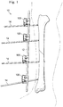
- Fig. 1 shows an external fixation system 10 attached to a patient's fractured tibia.
- the system 10 includes a rigid bar 12 and plurality of pins 14 drilled into the bone on opposing sides of the fracture.
- a clamping device 100 connects each pin 14 to the bar for rigid fixation and traction.
- Each pin 14 is received into a clamping device 100 by inserting the pin 114 between open top and bottom jaws of a fixator clamp of the clamping device 100.
- inserting the pin 14 triggers the fixator clamp to change from an open position to a provisionally locked position about the pin 14.
- the fixator clamp can be rotated about the pin, be axially displaced along the pin, or may pitch about the up or down around the cylindrical axis of the base element, but the jaws maintain the pin in the clamp.
- the bar 12 is introduced into another fixator clamp on the clamping device 100, forming a frame for the system.
- inserting the bar 12 triggers the fixator clamp to change from an open position to a provisionally locked position.
- the fixation components may be adjusted to provide angulation and orientation necessary to align the bone for healing. Additional bar-to-bar fixation components and/or bar-to-pin fixation components may be added to expand and connect the frame as required.
- the frame may be locked by changing the clamp from the provisionally locked condition to the locked condition.
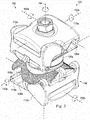
- Figs. 2 and 3 show an exemplary embodiment of a clamping device 100 according to one aspect of the present disclosure.
- the clamping device 100 includes a top fixator clamp 102 connected to a bottom fixator clamp 104.
- Each fixator clamp independently receives and secures a bar or pin, or alternatively, can be used to fixate bars to bars.
- a single clamp can be used to fixate either a pin or a bar to some other apparatus such as a ring or monolateral external fixation and/or deformity correction device.
- the clamp mechanism whether used singly or in pairs operates the same as each half is independent of one another.
- the clamps are substantially identical, while in other embodiments, the clamps are substantially similar, but have components sized or otherwise arranged to receive and secure different sized bars.
- the clamping device 100 includes only a single clamp 102, 104, with an alternative arrangement in place of the other clamp 102, 104. Since bars and pins may be interchangeably held by either of the clamps 102, 104, as referred to herein, the use of the term bar is intended to mean any elongate structure, including rods, shafts, pins, wires or otherwise, that extend from bones to the clamping device 100 or from other bars to the clamping device 100.
- the clamps 102, 104 each include a saddle base 106, an inner jaw 108, and an outer jaw 110.
- a release lever 112 operates to open the clamps 102, 104 and provisionally lock the clamps 102, 104 upon receipt of a bar.
- Each clamp 102, 104 of the clamping device 100 provides multiple degrees of freedom.
- Fig. 2 shows the degrees of freedom as a roll axis 150, a pitch axis 152, and a yaw axis 154 in the upper and lower clamps 102, 104.
- the roll axis 150 is the axis of a bar within the clamps and about which the clamping device 100 rotates.
- the pitch axis 152 is the axis about which the outer and inner jaws rotate relative to the saddle base 106 and relative to the opposing clamp.
- the yaw axis 154 is defined by a binding post (described below) and about which one of clamps 102, 104 can rotate relative to the other.
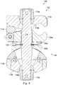
- Figs. 4 and 5 are cross-sectional views along lines 4-4 and 5-5 respectively showing inner features and components of the clamping device 100.
- the clamping device 100 includes a binding post 114 having spherical washers 116 and nuts 118 at each end. This binding post 114 passes through both the clamps 102, 104 and acts to hold the clamps together. Between the clamps 102, 104, a wave spring 120 provides a biasing force to space the clamps 102, 104 apart, enabling easy, independent rotation of the clamps 102, 104 about the binding post 114. This spring and its interaction with the saddle bases 106 of each of the clamps 102, 104 will be discussed further below.
- Each clamp 102, 104 of the clamping device 100 includes biasing wire springs 120 (only one shown in Fig. 5 ), a torsion spring 124, and a pin 126 which pivotally connects the inner jaw 108 to the release lever 112.
- the biasing wire springs 122 lie between and interact with the inner and outer jaws 108, 110 of the clamp 102 to bias the jaws toward an open or bar-receiving position.
- the torsion spring 124 operates between the inner jaw 108 and the release lever 112 to bias the release lever 112 toward a locked position.
- the release lever 112 may be rotated out of locking engagement with the outer jaw 110, at which time the wire spring 122 will bias the outer jaw 110 away from the inner jaw 108, thereby opening the jaws to receive a bar.
- the bar displaces the outer jaw 110, which releases the release lever 112.
- the torsion spring 124 biases the release lever 112 into a locking engagement with the outer jaw 110, overcoming the biasing force of the wire spring 122, and forcing the outer jaw 110 to pivot toward the inner jaw 108 to provisionally lock or secure the bar between the inner and outer jaws 108, 110.
- a surgeon can still 1) rotate the clamping device 100 about the roll axis 150 or slide the clamping device 100 axially along the bar to further manipulate the bars to a desired position in a roll direction, 2) rotate the clamps 102, 104 of the clamping device 100 relative to each other about the yaw axis 154 and the binding post 114 in a yaw direction, and 3) rotate the inner jaw 108 of each clamp 102, 104 about the pitch axis 152 relative to the respective saddle base 106 to pivot the clamps 102, 104 in a pitch direction.
- the surgeon can lock the clamping device 100 to the bars by tightening one or both nuts 118 on the binding post 114.
- a snap ring or other element or collar is secured at the center of the binding post 114 to allow for independent locking of either of clamps 102, 104.
- This snap ring allows for the locking of a single base element to the lower jaw and locking the jaw rather than locking both clamps at the same time.
- the collar is an integral part of the binding post 114.
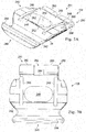
- Figs. 6A and 6B show an exemplary saddle base 106 of each clamp 102, 104.
- the saddle base includes an inner side 200, a concave outer-facing side 202, and a cylindrically shaped side wall 204 extending between the inner and outer-facing sides 200, 202.
- a central bore 206 extends through the saddle base 106 from the inner side 200 to the outer-facing side 202.
- This central bore 206 is sized to receive the binding post 114, as shown in Fig. 4 , with enough clearance for the saddle base 106 to rotate about the binding post 114 and the yaw axis 154 to provide rotation in the yaw direction.
- the central bore 206 is shaped to limit or restrict rotation about the binding post 114.
- the binding post 114 may have a non-circular cross-section and the central bore 206 may be shaped to match the non-circular cross-section in a way that either limits or prohibits rotation about the binding post 114.
- the inner side 200 includes a central circular-shaped surface 208 and a stepped shoulder 210.
- the central circular shaped surface 208 extends around the bore 206 and includes a circular array of radially extending splines that act to mate with the corresponding splines on the saddle base of the opposing clamp or on some other foundation if used without an opposing clamp.
- the splines resemble those on a poker chip and provide positive retention from planar rotation when the faces are clamped together.
- the stepped shoulder 210 on the inner side 200 extends about the central circular shaped surface 208 to the side wall 204 of the saddle base 106 and provides a seat for the wave spring 120 ( Fig. 4 ).
- the wave spring 120 interfaces with the stepped shoulder 210 of the saddle base 106 of each respective clamps 102, 104.
- the wave spring 120 biases the opposing shoulders 210 of each saddle base 106 apart, so that the radial splines on the opposing central circular shaped surfaces 208 are disengaged. Accordingly, the saddle bases 106, and therefore the clamps 102, 104, can rotate about the binding post 114 relative to each other.
- the wave spring 120 and the saddle shoulder 210 are sized so that upon tightening of the nut 118, the wave spring 120 can be compressed to lie along the shoulder 210 and the radial splines on the central circular shaped surfaces 208 of the opposing saddle bases 106 can engage to lock the clamps 102, 104 from pivoting relative to each other.
- the concave outer-facing side 202 of saddle base 106 includes parallel, longitudinal splines configured to interdigitate with corresponding splines on the inner jaw 108.
- the concave outer-facing side 202 forms a radius about a saddle surface axis, about which the inner jaw 108 pivots as it interfaces with the saddle base 106.
- the saddle base 106 may displace relative to the inner jaw 108 against the wave spring 120 to alternatingly engage and disengage the splines, permitting the saddle base 106 or the inner jaw 108 to rotate relative to one another about the pitch axis 152 in Fig. 2 .
- the angle of the longitudinal splines are such that they can be disengaged by radial displacement, and do not require longitudinal displacement to disengage due to any keystone effect.
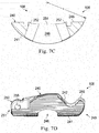
- Figs. 7A-D show the inner jaw 108.
- the inner jaw 108 cooperating with the outer jaw 110, directly interfaces with the bar to secure the bar in place.
- the inner jaw 108 includes an inner clamp face 240 facing toward the outer jaw 110 and an outer clamp surface 241 that interfaces with the saddle base 106.
- the inner clamp face 240 includes a transverse groove 242 for receiving a bar, a main surface 244 having a central bore 246 and bias member grooves 248, and a pivot portion 250.
- the transverse groove 242 is located at a front end 249 of the inner jaw 108 and the pivot portion 250 lies at the opposite rear end 254 of the main surface 244.
- the transverse groove 242 extends from one lateral side to another and is shaped to receive a bar, pin, or other fixation or stabilization component.
- the transverse groove 242 is formed between a hook portion 256 at the front end of the clamp that secures a bar in the clamp.
- the transverse groove 242 may be formed with a rounded bottom portion or may be formed of a series of flats or faces. Some embodiments may have a combination of both curves and faces.
- the depth of the transverse groove 242 may vary between different clamps, such as the top clamp 102 and the bottom clamp 104, depending on the size of the bar intended to be gripped by the respective clamp.
- the configuration and depth of the groove 242 may be configured to secure a smaller diameter bar, such as a bone pin or may be configured to secure a larger diameter bar, such as a frame bar. Further, in some embodiments, because the cross-section of the bars and pins may have shapes other than circular, the groove 242 may be shaped to also matingly interface with these bars and pins. For example, the groove 242 may include teeth, cut-outs, or other features that interface with bars having a non-smooth or non-circular outer surface.
- the central bore 246 is a transversely extending opening having a generally rectangular shape with a width and a length and the length being longer than the width.
- the central bore 246 has rounded or arching ends separated by substantially parallel side edges spaced by the width.
- the bore is cylindrical or conical-shaped at its ends 252 such that the bore length increases as the bore depth approaches the outer clamp surface 241.
- bore sidewalls 254 are substantially parallel to each other, maintaining the bore width substantially constant.
- the binding post 114 fits within the central bore 246 as shown in Fig. 4 , and provides only limited movement relative to the post 114 in the longitudinal, or width direction.
- the inner jaw 108 may move relative to the binding post 114 substantially more in the transverse, or length direction, to change the pitch of the inner jaw 108 relative to the post 114.
- This length is the result of a subtended arc who's vertex is coincident with the axis of the cylindrical surface ate ends 252.
- the inner jaw 108 pivots relative to the saddle base 20 degrees in each direction, giving a pivot range of 40 degrees.
- the range of pivot articulation may be greater or less than 40 degrees, and may be affected by the diameter of the binding post 114, the length of the central bore 246, as well as the angle of the bore ends 252.
- the two bias member grooves 248 in the main surface 244 extend from the transverse groove 242 rearwardly toward the pivot portion 250. These two bias member grooves 248 receive the wire springs 122 ( Fig. 5 ) that operate to bias the inner jaw 108 and the outer jaw 110 to an open position.
- the grooves 248 in the embodiment shown are parallel to each other, and have a decreasing depth from the transverse groove 242 toward the pivot portion 250, ultimately ending where the bias member grooves 248 meet the main surface 244.
- the pivot portion 250 includes a cylindrical passage 258 that receives the pin 126 ( Fig. 5 ) and cooperates with the release lever 112 in the form of a hinge.
- the pivot portion 250 includes two connectors 260 separated by a centrally located gap 262. This gap 262 is sized to receive the torsion spring 124 ( Fig. 5 ), as will be discussed further below.
- the outer clamp surface 241 is a semi-cylindrical shaped surface that includes parallel, longitudinal splines shown in Figs. 7C and 7D . These are configured to interdigitate with the corresponding splines on the saddle outer facing side 202 shown in Fig. 6B .
- the cylindrical shaped surface defines a radius r about which the inner jaw 108 pivots to provide the range of motion. Naturally, pivoting only occurs when the inner jaw 108 and the saddle base 106 are spaced so that the splines are not engaged. This may occur, for example, by displacing the saddle base towards the wave spring or in some embodiments.
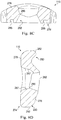
- Figs. 8A-8D show the outer jaw 110 in greater detail.
- the outer jaw 110 includes a front end 272, a rear end 274, an inner clamp face 276, and an outer clamp surface 278.
- the inner clamp face 276 includes a bar-receiving transverse groove 280 adjacent the front end 272, a central bore 282, and bias member grooves 285. Similar to the groove 242 on the inner jaw 108 described above, the transverse groove 280 extends from one lateral side to another and is shaped to cooperate with the inner jaw 108 to receive a bar, pin or other fixation or stabilization component.
- a hook portion 282 at the front end 272 defines a first portion of the transverse groove 280 and, as shown in the cross-section of Fig. 4 , aligns with the inner jaw hook portion 256 to define an opening through which the bar may be introduced.
- the transverse groove 280 may be formed with a rounded bottom portion, flats, faces, or some combination of both.
- the depth and shape of the groove 280 is the same as the depth and shape of the groove 248. Accordingly, the discussion above relating to the transverse groove 248 is equally applicable to the transverse groove 280.
- the central bore 282 includes features that enable it to provide articulation relative to the binding post 114 in a manner that the outer jaw articulation matches that of the inner jaw 108.
- Figs. 8C and 8D show the outer jaw 110 in cross-section and, along with the views in Fig. 8A and 8B , provide an indication of the multiple surface aspects of one exemplary central bore 282.
- the central bore 282 is generally hour-glass shaped, with a narrowing neck 286 located between the inner clamp face 276 and the outer clamp surface 278.
- the central bore 282 is relatively rectangular shaped with a width and a length, the length being greater than the width. From the inner clamp face 276, the bore tapers inwardly toward the neck 286, with the inner bore surfaces including curved portions as well as planar portions.
- the central bore portion between the neck 286 and the inner clamp face 276 is arranged and shaped to permit articulation relative to the binding post 114 in a manner to match articulation of the inner jaw 108 so that during articulation, the inner clamp face 276 of the outer jaw 110 faces the inner clamp face 240 of the inner jaw 108.
- the central bore 282 is sized to permit pivot rotation in the lateral direction of the outer jaw 110 within, for example, a pivot range of 40 degrees, matching that of the inner jaw 108. As discussed above, other pivot ranges are contemplated and considered to be within the scope of this disclosure.
- the outer jaw 110 in this embodiment is configured to also provide articulation in the longitudinal direction or front-to-rear direction.
- the longitudinal direction also includes side walls tapering from the neck toward the inner clamp face 276.
- These inner clamp faces are not symmetrically disposed, but permit more articulation in one longitudinal direction than the other.
- the inner clamp surface permits articulation from a center point in one direction of twenty degrees, and in the other direction, about 8 degrees.
- the outer jaw 110 is configured to pivot in the longitudinal direction relative to the binding post 114 up to about 28 degrees.
- the different angles, curved, and flat surfaces can be seen in Figs. 8B-D .
- the central bore portion between the neck 286 and the outer clamp surface 278 is arranged and shaped to permit articulation relative to the binding post 114 in a manner that permits the inner clamp surface 278 to pivot and face the inner clamp surface 240 of the inner jaw 108.
- the central bore 282 widens from the neck 286 toward the outer clamp surface 278.
- the central bore portion between the neck 286 and the outer clamp surface 278 is nonsymmetrical.
- the inner walls are formed with concave curves 287 near the neck 286. These curves 287 are shaped to interface with the spherical washer 116 in Fig. 4 and provide an articulation surface for the outer jaw 110 to articulate relative to the spherical washer 116 as the outer jaw 110 displaces to open and close the clamp 102.
- the outer jaw 110 displaces relative to the binding post 114 in the lateral direction as the inner jaw 108 pivots with respect to the saddle base 106.
- the outer jaw 110 displaces relative to the inner jaw 108 to open the jaws to receive a bar into the transverse groove 280.
- This displacement is in the longitudinal direction, and as shown in Figs. 4 and 8 , the neck 286 of the central bore is shaped large enough to permit pivoting about the center of the concave curves longitudinally as well as laterally.
- the bias member grooves 285 extend longitudinally on each side of the central bore 282. These grooves extend from the transverse groove 280 rearwardly toward the rear end 274 and are sized and located to align with the bias member grooves 248 on the inner jaw 108. Together the bias member grooves 285 on the outer jaw 110 and the bias member grooves 248 on the inner jaw 108 receive the wire springs 122 ( Fig. 5 ) which act between the two jaws 108, 110 to bias the outer jaw to an open, bar-receiving position.
- These grooves 285 on the outer jaw 110 include a securing feature 288 formed as an inwardly extending indentation shaped to receive an end of the wire springs 122, as shown in Fig. 5 .
- the rear end 274 of the outer jaw 110 includes a locking interface 290 shaped to contact the release lever 112 to secure the outer jaw 110 in the open position, and shaped to release the outer jaw 110 to close to the provisionally locked position.
- This locking interface 290 extends obliquely relative to the inner clamp face 276 and the outer clamp surface 278 and includes a protruding edge 292 that acts as a catch for the release lever 112 when the clamp 102 is in the open position.
- the edge 292 is an indentation or other catch.
- Fig. 9 shows the release lever 112.
- it includes a locking bar 320 extending between, and integrally formed with, grips 322.
- a pin receiving hole 324 in the grips 322 receives the pin 126 ( Fig. 5 ), which extends parallel to the locking bar 320.
- the pin 126 also passes through the pivot portion 250 and the torsion spring 124 to pivotally secure the release lever 112 in place on the inner jaw 108.
- the locking bar 320 includes a generally irregular quadrilateral cross-sectional shape, but also includes mild concave and convex curves.
- the curves may be concentric about a pivot axis formed by the pin 126 and the pin receiving holes 324. Accordingly, the curved surface may be concentric with the outer surface of the cylindrical pin 126.
- the locking bar 320 may interface with the locking interface 290 on the outer jaw 110 to place the outer jaw 110 in the provisionally locked condition. Likewise, when pivoted about the pin 126, the locking bar 320 may interface with the rear end 274 of the outer jaw 110 to permit the outer jaw 110 to rest in the opened bar-receiving position.
- a cutout 324 Centrally disposed in the curved surface of the locking bar 320 is a cutout 324 facing the pin-receiving holes 324. This cutout 324 is sized to receive the torsion spring 124 as it extends about the pin 126. The torsion spring 124 applies a biasing force on the release lever 112 to place the release lever 112 in the provisionally locked position.
- the grips 322 are ergonomically shaped for easy grasping with a thumb and forefinger. These are generally triangularly shaped and include protruding edges permitting a surgeon to grasp the release lever 112 with two fingers to pivot the release lever about the pin so that the outer jaw 110 moves to the open, bar-receiving position.
- Figs. 10A-C show the top clamp 102 in the open position, during bar insertion, and in the closed position, respectively.
- the release lever 112 is pivoted about the pivot connection so that the locking bar 320 lies behind the rear end 274 of the outer jaw 110.
- a surgeon may place the clamping device 100 in the open position by grasping the release lever 112 between his thumb and forefinger and pivoting the release lever 112 about the pin 126 to overcome the force of the biasing torsion spring 124.
- the wire spring (not shown in Fig. 10A ) biases the outer jaw 110 to pivot about the spherical washer 116 to an open position, separating the outer jaw and inner jaw hook portions 282, 256.
- the shape and loading articulates the top jaw 110 to open the front end of the clamp 102. Accordingly, here, the device 100 is in a cocked position.
- Fig. 10B shows a bar 260 being inserted between the inner and outer jaws 108, 110.
- the outer jaw 110 is forced rearwardly. This rearward movement pivots the outer jaw about the spherical washer 116 enough to raise the rear end of the outer jaw 110 above the locking bar 320.
- the biasing force of the torsion spring 124 pivots the release lever 112 so that the locking bar 320 acts against the locking interface surface 290 of the outer jaw 110.
- the torsion spring force overcomes the biasing force of the wire springs and as the release lever 112 continues to pivot, the locking bar 320 continues to force the outer jaw 110 further closed, thereby snapping shut to grip the bar 260.
- Fig. 10C shows the clamp 102 in the provisionally closed position.
- the bar 260 is provisionally secured within the clamp 102 between the outer and inner jaws 110, 108.
- the bar 260 may be rotated within the clamp 102 or the clamp may be rotated about the bar, the clamp 102 may be slid along the bar 260, and the outer and inner jaws 110, 108 may be pivoted relative to the saddle base 106 and rotated about the binding post 114.
- the clamp 102 snaps onto a bar but permits continued adjustment as the surgeon finishes locating the pins or building the frame.
- the surgeon locks the clamp 102 against further movement by tightening one or both of the nuts 118 on the binding post 114.
- the use of a collar or snap ring on the binding post 114 may allow independent locking of both clamps 102, 104. This compresses the wave spring 120 and the radially extending splines in the opposing saddle bases 106 engage each other. This also meshes the splines on the inner jaw 108 and the concave side of the saddle base 106, as well as drives the spherical washer 116 tight against the outer jaw 110. The outer jaw 110 then is forced against the inner jaw 108 and the release lever 112 to more tightly secure the bar in place between the jaws. Thus, in a fully locked state, the clamping device 100 is locked against all relative movement of the clamps, including releasing the bar.
- the surgeon performs the steps in reverse. Particularly, he first loosens the nuts, placing the clamping device 100 in the provisionally locked state. Then he may grasp and rotate the release lever 112 so that the locking bar 320 is out of engagement with the outer jaw 110. The outer jaw 110 will open and the bar may be removed. Or course, if the clamps 102, 104 are independent lockable, such as when a snap ring or collar is incorporated into the binding post 114, then the clamps may be locked or released independently.
- Figures 11-15 show an exemplary clamping device not falling within the scope of the claims, referred to herein as 400.
- the device 400 is a low-profile clamping device that, like the device 100 discussed above, minimizes the pin to bar centerline distance. Large centerline distances increase the working envelope and increase the moment arm of the clamping device, subjecting the clamping device to increased moment loading necessitating a larger device.
- 11-15 minimizes the pin to bar centerline distance by replacing the ball joint with two cylindrical surfaces on the inner jaw halves (one for each clamp half) and retaining a revolute joint between the two clamp assemblies so that it achieves the roll, pitch and yaw of a ball joint while also adding two additional degrees a freedom, namely the ability for the jaw halves to translate along the cylinder axes allowing for greater ease of assembly, fracture reduction, and load sharing while maintaining a close pin to bar centerline distance resulting in a more compact, lower loaded device.
- the exemplary clamping device 400 includes both a top clamp 402 as a bar clamp and a bottom clamp 404 as a pin clamp.
- the top and bottom clamps 402, 404 each operate in an identical manner and differ only in the size of the cylinder that the pin and bar clamp can accommodate.
- the clamp pair 402, 404 can be used to fixate pins to pins, pins to bars, or bars to bars or a single clamp can be used to fixate either a pin or a bar to some other apparatus such as a ring or monolateral external fixation and/or deformity correction device.
- the clamp mechanism whether used singly or in pairs operates the same as each half is independent of one another.
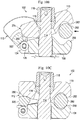
- Fig. 11 shows the top clamp 402 in cross-section and the clamp 404 as a solid view.
- Each clamp 402, 404 includes a saddle base 406, an inner jaw 408, an outer jaw 410, and a release slide 412. These are connected together by a binding post 414, a compression sleeve 416, and a tightening nut 418.
- the inner and outer jaw 408, 410 cooperate to form an opening 420 for receiving a bar therein.
- Each clamp 402, 404 of the clamping device 400 provides multiple degrees of freedom.
- Fig. 11 shows the degrees of freedom as a roll axis 422, a pitch axis 424, and a yaw axis 426 in the upper clamp 402.
- the roll axis 422 is the axis of a bar within the clamp 402 and about which the clamping device 400 rotates.
- the pitch axis 424 is the axis about which the outer and inner jaws 410, 408 rotate relative to the saddle base 406 and relative to the lower clamp 404.
- the yaw axis 426 is defined by the binding post 414 and about which one of clamps 402, 404 can rotate relative to the other. As can be seen in Fig.
- the two pitch axes 152 are offset from each other and lie in parallel planes. Offsetting the axes in this way assists in lowering the overall profile of the device 100. In some examples, these may be offset a distance within the range of about 5.08 mm (.2 inch) or greater. Other examples may have the axes offset more than 12.7 mm (.5 inch). Yet others have the axes offset more or less than these exemplary distances.
- the binding post 414 secures the top and bottom clamps 402, 404 together, or in other examples, secures one of the clamps to another fixation or other device.
- the view in Fig. 11 shows only one half of the binding post 414, as the other half extends into the bottom clamp 404.
- the binding post axis corresponds to the yaw axis 426, about which the clamps 402, 404 can rotate relative to each other and relative to the binding post 414.
- the binding post 414 includes a spherical ball joint 415.
- the center of this spherical joint 415 coincides with both the yaw axis 426 and the pitch axis 424 of the cylindrical surface of the base 406 described below. This relationship allows the clamp 402, as well as any pin or bar contained within the clamp 402 to pivot about its center and rotate about the pitch axis 424.
- the base 406a of the upper clamp 402 includes a concave saddle portion 428 that interfaces with the lower outer surface 430 the inner jaw 408.
- the concave saddle portion 428 has an axis corresponding to the pitch axis 424, and about which the inner jaw 408, the outer jaw 410, and the release slide 412 can rotate.
- the base 406a has a circular array of radial splines on its bottom surface 432 that act to mate with radial splines on the corresponding base 406b on the lower clamp assembly 404 or some other foundation if used individually. Similar to those splines described above, the splines resemble those on a poker chip and provide positive retention from planar rotation when the bottom surfaces 432 are clamped together.
- the concave saddle portion 428 side of the base 406a is a cylindrical surface which in some examples, has a series of longitudinal splines as shown and discussed above with reference to the clamping device 100. These longitudinal splines mate to similar splines on the bottom surface 430 of the inner jaw 408 and act to provide positive rotation retention when in the clamped or locked state.
- the lower or inner jaw 408 is cylindrically shaped on its lower surface 430 and includes longitudinal splines that interdigitate with those on the base 406a when in the clamped state.
- the longitudinal splines may be similar to those shown in and described with reference to Fig. 7A , 7C and 7D .
- a transverse groove formed in the inner jaw 408 in part creates the opening 420 that accepts the pin or bar.
- the inner jaw 408 includes a central clearance bore 434 or hole through which the binding post extends.
- This central bore 434 is sized and configured to provide clearance to the binding post 414 that allows for both rotation about the pitch axis 424 in the amount of, for example, +/- 20 degrees as well as axial translation along the pitch axis 424 as indicated by the arrow shown.
- the amount of axial translation may be limited by the size of the binding post and the size of the central bore 434. In some examples, the permitted axial translation is within a range of 2.54 mm to 25.4 mm (0.1 to 1 inch). When both clamps 402, 402 translate, the total amount of translation for the device 400 can be up to double this range.
- a hinge pin 436 connects the inner jaw 408 and the outer jaw 410.
- the inner jaw 408 includes a recess into which a portion of the outer jaw extends.
- the hinge pin 436 passes through both the inner jaw and the outer jaw providing a pivot hinge connection that permits the outer and inner jaws 408, 410 to be opened and closed to achieve sufficient clearance at the opening 420 to receive a bar or pin.
- the outer jaw 410 half has a transverse cut (not shown) that accepts the pin or bar.
- the outer jaw includes a dovetail slot 430 that accepts the release slide 412, and allows it to slide relative to the outer jaw 410.
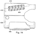
- the release slide 412 cooperates with the outer jaw 410 to either open or close the opening 430. It has a corresponding dovetail feature 440 which mates with the dovetail slot on the outer jaw 410. Because this dovetail slot 438 on the outer jaw 410 is on a slope, when the release slide 412 is slid rearward it also moves downward, removing the constraint on the outer jaw 410 and allowing the outer jaw 410 to open in order to accept the pin or bar. Once the release slide 412 is slid back up the ramp it acts as a door stop in preventing the outer jaw 410 from opening up, preventing the inadvertent release of the pin or bar. Some examples include a compression spring or other biasing member that biases the release slide 412 into the upper locked position.
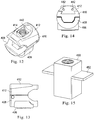
- Fig. 16 shows a partial cross-sectional view of the clamp 402 with an exemplary biasing member 444 that applies loading to bias the release slide 412 into the locked position.
- the biasing member is disposed half in the upper jaw 410 and half in the release slide 412.
- FIG. 16 shows a partial cross-sectional view of the clamp 402 with an exemplary biasing member 444 that applies loading to bias the release slide 412 into the locked position.
- the biasing member is disposed half in the upper jaw 410 and half in the release slide 412.
- FIG. 16 shows a partial cross-sectional view of the clamp 402 with an exemplary biasing member 444 that applies loading to bias the release slide 412 into the locked position.
- the biasing member is disposed half in the upper jaw 410 and half in the release slide 412.
- FIG. 16 shows a partial cross-sectional view of the clamp 402 with an exemplary biasing member 444 that applies loading to bias the release slide 412 into the locked position.
- the biasing member is disposed half in
- one or more guide pins 442 extends through the release slide 412 and across the central clearance bore 434. As shown in Fig. 14 , these guide pins 442 may be introduced through a rear portion of the release lever. The guide pins pass through receiving bores (not shown) on compression sleeve 416 securing the compression sleeve to the release slide 412. During translation as well as during actuation of the release lever, the guide pines 412 slide relative to the compression sleeve 416.
- the compression sleeve instead of employing guide pins to secure the compression sleeve in the bore of the release slide, the compression sleeve itself includes extending protrusions that fit into and slide within guide slots formed inside the release slide bore.
- a compression sleeve 450 is shown in Fig. 15 .
- the compression sleeve 450 includes wings 452 protruding from opposing sides that fit within a guide slot formed in the bore sidewall of the release slide 412, securing the compression sleeve 416 to the release slide 412.
- the wings allow the compression sleeve 416 to slide front to back with respect to the release slide 412 , but does not allow it to move up and down relative to the release slide 412.
- On the inner cylindrical bore is a left hand helical thread that engages with the tightening nut 418.
- the tightening nut 418 engages with the compression sleeve 416 on its outer threaded cylindrical surface. It includes at its lower end a spherical joint that mates with the binding post 414, through its center is a broached hexagonal hole that accepts a tool for tightening.
- a surgeon may slide back the release slide 412 relative to the outer jaw 410. This opens the outer jaw 410 relative to the inner jaw 408. Once a bar or pin is in the transverse cuts between the outer and inner jaws 410, 408, the release slide 412 may be either moved, or snapped back toward the front of outer jaw 410. This closes the jaw positively retaining the pin or bar from detachment but not firmly fixating it. Accordingly this is a provisionally locked position, allowing the pin or bar to move in accordance with the degrees of freedom of the clamping device 400.
- Tightening the tightening nut 418 provides a clamping force between the binding post 414 and the release slide 412 effectively clamping together the base 406, the outer and inner jaws 408, 410, and the release slide 412, and applying pressure to the pin or bar in the clamp. Because of the slight slope between the outer jaw 410 and the release slide 412, the release slide 412 acts as a door stop on the outer jaw 410. Thus, the greater the clamping force the greater the resistance to sliding thus preventing the jaws from opening. Releasing the pin may be accomplished by reversing the steps.
- this disclosure is directed to an exemplary clamping device for an external fixation system.
- the device includes a first clamping system connected to a second clamping system by a saddle assembly.
- the saddle assembly includes first and second outwardly facing concave surfaces that respectively interface with the first and second clamping systems.
- the first and second outwardly facing concave surfaces have a respective first and a second pitch axis.
- the first clamping system is moveable relative to saddle assembly to pivot within a range of more than 20 degrees about the first pitch axis and the second clamping system moveable relative to saddle assembly to pivot within a range of more than 20 degrees about the second pitch axis.
- the first and second pitch axes are offset by more than 12.7 mm (.5 inch).
- the first and second pitch axes lie in parallel planes.
- the first and second clamping system are respectively moveable relative to saddle assembly to pivot within a range of 40 degrees or more about the first and second pitch axes, respectively.
Claims (10)
- Spannvorrichtung (100) für ein externes Befestigungssystem, mit:einem Spannsystem (102) und einer Ständerkomponente (114), die sich in das Spannsystem (102) erstreckt;wobei das Spannsystem (102) aufweisteine äußere Klaue (110, 110a);eine innere Klaue (108, 108a) mit einer Innenfläche, die der äußeren Klaue (110, 110a) zugewandt ist, wobei die äußere und die innere Klaue zusammen eine Öffnung zur Aufnahme eines Fixierelements (12) des externen Befestigungssystems bilden;dadurch gekennzeichnet, dassdie Spannvorrichtung (100) ferner ein Auslösesystem aufweist, das die äußere Klaue (110, 110a) und die innere Klaue (108, 108a) von einem gespannten, offenen Stab aufnehmenden Zustand in einen provisorisch verriegelten Zustand überführt, der ein Entfernen eines Fixierelements (12) aus dem Zwischenraum zwischen den Klauen verhindert, aber ein Gleiten und Rotieren eines Fixierelements (12) relativ zu den Klauen ermöglicht,wobei das Auslösesystem eine Freigabekomponente (112), die drehbar an der inneren Klaue (108) angebracht ist, und ein Vorspannelement (124) aufweist, das die Freigabekomponente (112) in den provisorisch verriegelten Zustand vorspannt, wobei die Freigabekomponente gleitend mit der äußeren Klaue (110) in Eingriff tritt, um die äußere Klaue (110) in den provisorisch verriegelten Zustand vorzuspannen.
- Spannvorrichtung nach Anspruch 1, wobei die Freigabekomponente (112) ein erstes und ein zweites Greifelement (322, 322) aufweist, die durch einen schräg verlaufenden Stab (320) verbunden sind, der mit dem Vorspannelement (124) und der äußeren Klaue (110) in Verbindung steht.
- Spannvorrichtung nach einem der vorhergehenden Ansprüche, wobei die Freigabekomponente (112) ein drehbarer Freigabehebel (112) ist, wobei der Freigabehebel (112) so drehbar ist, dass er die Klauen (110, 108) einen selbsthaltenden gespannten Zustand zur Aufnahme des Fixierelements (12) zwischen den Klauen (110, 108) überführt und mit den Klauen (110, 108) in Eingriff tritt und diese in den provisorisch verriegelten Zustand drückt.
- Spannvorrichtung nach Anspruch 3, wobei das Vorspannelement (124) den Freigabehebel (112) so vorspannt, dass die äußere Klaue (110) in Richtung zu der inneren Klaue (108) in Drehung versetzt wird, sodass die Klauen in den provisorisch verriegelten Zustand versetzt werden.
- Spannvorrichtung nach einem der Ansprüche 2 bis 4, wobei der Stab (320) gleitend mit der äußeren Klaue (110) derart in Eingriff tritt, die er Klauen (18, 110) in den provisorisch verriegelten Zustand drückt.
- Spannvorrichtung nach einem der vorhergehenden Ansprüche, die ferner eine Befestigungskomponente (118a) aufweist, die mit der Ständerkomponente (114) in Verbindung steht und derart ausgebildet ist, dass ein Vorgang des Befestigens durch die Befestigungskomponente (118a) die Klauen (108, 110) in einen verriegelten Zustand versetzt, der ein Entfernen des Fixierelements (12) aus dem Zwischenraum zwischen den Klauen (108, 110) verhindert und verhindert, dass das Fixierelement (12) sich relativ zu den Klauen (108, 110) verschiebt und dreht.
- Spannvorrichtung nach einem der vorhergehenden Ansprüche, die ferner ein Vorspannelement (122) aufweist, das die Klauen (108, 109) in den offenen Zustand vorspannt.
- Spannvorrichtung nach einem der Ansprüche 3 bis 7, wobei in dem provisorisch verriegelten Zustand zumindest ein Teil des Freigabehebels (112) mechanisch bei Verschiebung der Klauen (108, 110) relativ zueinander mit diesen mechanisch in Wechselwirkung tritt, sodass verhindert wird, dass die Klauen (108, 110) in den offenen Zustand verschoben werden.
- Spannvorrichtung nach Anspruch 8, wobei der mindestens eine Teil des Freigabehebels (112), der bei Verschiebung der Klauen (108, 110) mechanisch mit diesen in Wechselwirkung tritt, zwischen den Klauen angeordnet ist, wenn das Auslösesystem in dem provisorisch verriegelten Zustand ist.
- Spannvorrichtung nach einem der vorhergehenden Ansprüche, wobei:
die Ständerkomponente (114) eine Hochachse (154) hat, wobei die Klauen (108, 110) an der Ständerkomponente (114) befestigt und um die Hochachse (154) drehbar sind, und die Öffnung zur Aufnahme des Fixierelements (12) entlang einer Rollachse (150a) dient, die ungefähr senkrecht zu der Hochachse (154) ist.
Applications Claiming Priority (3)
| Application Number | Priority Date | Filing Date | Title |
|---|---|---|---|
| US99553507P | 2007-09-27 | 2007-09-27 | |
| EP08833281.2A EP2197372B1 (de) | 2007-09-27 | 2008-09-26 | Klemmgerät zur externen fixierung und stabilisierung |
| PCT/US2008/077800 WO2009042836A1 (en) | 2007-09-27 | 2008-09-26 | Method and clamping apparatus for external fixation and stabilization |
Related Parent Applications (1)
| Application Number | Title | Priority Date | Filing Date |
|---|---|---|---|
| EP08833281.2A Division EP2197372B1 (de) | 2007-09-27 | 2008-09-26 | Klemmgerät zur externen fixierung und stabilisierung |
Publications (2)
| Publication Number | Publication Date |
|---|---|
| EP3067001A1 EP3067001A1 (de) | 2016-09-14 |
| EP3067001B1 true EP3067001B1 (de) | 2019-04-17 |
Family
ID=40509226
Family Applications (2)
| Application Number | Title | Priority Date | Filing Date |
|---|---|---|---|
| EP16164900.9A Active EP3067001B1 (de) | 2007-09-27 | 2008-09-26 | Spannvorrichtung zur externen fixierung und stabilisierung |
| EP08833281.2A Active EP2197372B1 (de) | 2007-09-27 | 2008-09-26 | Klemmgerät zur externen fixierung und stabilisierung |
Family Applications After (1)
| Application Number | Title | Priority Date | Filing Date |
|---|---|---|---|
| EP08833281.2A Active EP2197372B1 (de) | 2007-09-27 | 2008-09-26 | Klemmgerät zur externen fixierung und stabilisierung |
Country Status (4)
| Country | Link |
|---|---|
| US (4) | US8241285B2 (de) |
| EP (2) | EP3067001B1 (de) |
| JP (2) | JP5463574B2 (de) |
| WO (1) | WO2009042836A1 (de) |
Families Citing this family (79)
| Publication number | Priority date | Publication date | Assignee | Title |
|---|---|---|---|---|
| US7708736B2 (en) * | 2006-02-22 | 2010-05-04 | Extraortho, Inc. | Articulation apparatus for external fixation device |
| EP1920720B1 (de) * | 2006-10-13 | 2014-03-19 | Stryker Trauma SA | Mittel zur Verhinderung der Wiederverwendung einer medizinischen Vorrichtung |
| EP3067001B1 (de) * | 2007-09-27 | 2019-04-17 | Zimmer, Inc. | Spannvorrichtung zur externen fixierung und stabilisierung |
| US8085481B2 (en) * | 2009-05-26 | 2011-12-27 | Jerry Paul Hill | Lens drive motor mount |
| US8282636B2 (en) * | 2009-08-10 | 2012-10-09 | Imds Corporation | Orthopedic external fixator and method of use |
| US9066757B2 (en) * | 2009-08-10 | 2015-06-30 | Virak Orthopedic Research Llc | Orthopedic external fixator and method of use |
| ES2667759T3 (es) * | 2009-09-11 | 2018-05-14 | Stryker European Holdings I, Llc | Dispositivo de sujeción fácil de limpiar |
| ES2668075T3 (es) * | 2009-09-11 | 2018-05-16 | Stryker European Holdings I, Llc | Componente de fijación externa |
| US8858555B2 (en) | 2009-10-05 | 2014-10-14 | Stryker Trauma Sa | Dynamic external fixator and methods for use |
| IT1396145B1 (it) * | 2009-11-05 | 2012-11-16 | Citieffe Srl | Fissatore esterno polivalente. |
| EP2319436B1 (de) * | 2009-11-06 | 2013-02-13 | ORTHOFIX S.r.l. | Klemme für Fixateur externe |
| CN103260535B (zh) * | 2010-07-01 | 2016-08-03 | 捷迈有限公司 | 多重锁定式外部固定夹具 |
| US8945128B2 (en) | 2010-08-11 | 2015-02-03 | Stryker Trauma Sa | External fixator system |
| ES2549030T3 (es) | 2010-08-11 | 2015-10-22 | Stryker Trauma Sa | Sistema de dispositivo de fijación externo |
| US11141196B2 (en) | 2010-08-11 | 2021-10-12 | Stryker European Operations Holdings Llc | External fixator system |
| ES2541831T3 (es) | 2010-10-07 | 2015-07-27 | Stryker Trauma Sa | Elemento de acoplamiento para un dispositivo de fijación externo |
| EP2627273B1 (de) | 2010-10-12 | 2017-03-01 | Zimmer, Inc. | Externe chirurgische fixationsklammer mit drehlager |
| EP3388007A3 (de) | 2010-10-12 | 2019-02-20 | Zimmer, Inc. | Externe fixationsklemmenanordnung mit einzelarretierung |
| US8728078B2 (en) | 2010-11-04 | 2014-05-20 | Zimmer, Inc. | Clamping assembly with links |
| EP2648634B1 (de) | 2010-12-09 | 2016-05-18 | Zimmer, Inc. | Drehendes schloss für externe fixierklammern |
| WO2012078893A1 (en) * | 2010-12-09 | 2012-06-14 | Extraortho, Inc. | External fixation clamp with cam driven jaw |
| USD704840S1 (en) | 2010-12-14 | 2014-05-13 | Stryker Trauma Sa | Hinge coupling |
| USD683461S1 (en) | 2010-12-14 | 2013-05-28 | Stryker Trauma Sa | Hinge coupling |
| EP2465454B1 (de) | 2010-12-14 | 2015-04-08 | Stryker Trauma SA | Fixierungsklemme mit Einstellrad |
| USD720853S1 (en) | 2010-12-14 | 2015-01-06 | Stryker Trauma Sa | Fixation clamp |
| ES2540256T3 (es) | 2010-12-14 | 2015-07-09 | Stryker Trauma Sa | Pinza de fijación |
| EP2465455B1 (de) | 2010-12-14 | 2015-04-08 | Stryker Trauma SA | Fixierungsklemme |
| US8992579B1 (en) * | 2011-03-08 | 2015-03-31 | Nuvasive, Inc. | Lateral fixation constructs and related methods |
| WO2012158698A1 (en) * | 2011-05-17 | 2012-11-22 | Extraortho, Inc. | External fixation clamping system using a trigger mechanism and stored spring energy |
| USD663030S1 (en) | 2011-06-14 | 2012-07-03 | Styker Trauma SA | Fixation clamp |
| USD682426S1 (en) | 2011-06-14 | 2013-05-14 | Stryker Trauma Sa | Fixation clamp |
| ES2581533T3 (es) * | 2011-12-06 | 2016-09-06 | Stryker European Holdings I, Llc | Pinza de fijación |
| US8337532B1 (en) | 2011-12-08 | 2012-12-25 | Spine Wave, Inc. | Methods for percutaneously extending an existing spinal construct |
| US9060815B1 (en) | 2012-03-08 | 2015-06-23 | Nuvasive, Inc. | Systems and methods for performing spine surgery |
| US9064609B2 (en) * | 2012-05-16 | 2015-06-23 | Ge-Hitachi Nuclear Energy Americas Llc | Mechanical connections and methods |
| US9101398B2 (en) | 2012-08-23 | 2015-08-11 | Stryker Trauma Sa | Bone transport external fixation frame |
| US9301782B2 (en) | 2012-09-04 | 2016-04-05 | Zimmer, Inc. | External fixation |
| US9924969B2 (en) | 2012-09-04 | 2018-03-27 | Zimmer, Inc. | External fixation |
| US9610798B2 (en) * | 2013-02-20 | 2017-04-04 | Typical 4, LLC | Trophy mount and skull clamp |
| US9155561B2 (en) | 2013-03-06 | 2015-10-13 | Stryker Trauma Sa | Mini-rail external fixator |
| US9408635B2 (en) * | 2013-03-15 | 2016-08-09 | Wright Medical Technology, Inc. | External fixation |
| US9370380B2 (en) * | 2013-03-15 | 2016-06-21 | Dne, Llc | External bone fixation system |
| US10258378B2 (en) | 2013-03-15 | 2019-04-16 | Dne, Llc | External bone fixation system |
| US9827011B2 (en) | 2013-03-15 | 2017-11-28 | Biomet Manufacturing, Llc | Polyaxial pivot housing for external fixation system |
| ITMI20130407A1 (it) * | 2013-03-18 | 2014-09-19 | Orthofix Srl | Dispositivo di fissazione esterna |
| US9517089B1 (en) | 2013-10-08 | 2016-12-13 | Nuvasive, Inc. | Bone anchor with offset rod connector |
| US9962188B2 (en) * | 2013-10-29 | 2018-05-08 | Cardinal Health 247. Inc. | External fixation system and methods of use |
| US9962187B2 (en) | 2014-08-11 | 2018-05-08 | Zimmer, Inc. | External fixation |
| WO2016035053A1 (en) * | 2014-09-04 | 2016-03-10 | Mikai S.P.A. | External fixation clamp |
| WO2016035050A1 (en) * | 2014-09-04 | 2016-03-10 | Mikai S.P.A. | External fixing system for orthopaedic exoskeleton |
| US10264959B2 (en) | 2014-09-09 | 2019-04-23 | Medos International Sarl | Proximal-end securement of a minimally invasive working channel |
| US10111712B2 (en) | 2014-09-09 | 2018-10-30 | Medos International Sarl | Proximal-end securement of a minimally invasive working channel |
| WO2016205128A2 (en) | 2015-06-17 | 2016-12-22 | Nathan Erickson | Ankle fixation system |
| US10531896B2 (en) | 2015-08-10 | 2020-01-14 | Stryker European Holdings I, Llc | Distraction tube with wire clamp |
| US9872707B2 (en) * | 2015-12-03 | 2018-01-23 | Globus Medical, Inc. | External fixator assembly |
| US9943337B2 (en) * | 2015-12-03 | 2018-04-17 | Globus Medical, Inc. | External fixator assembly |
| US10682160B2 (en) | 2015-12-03 | 2020-06-16 | Globus Medical, Inc. | External fixator assembly |
| US10517647B2 (en) | 2016-05-18 | 2019-12-31 | Medos International Sarl | Implant connectors and related methods |
| US10321939B2 (en) | 2016-05-18 | 2019-06-18 | Medos International Sarl | Implant connectors and related methods |
| US11291476B2 (en) | 2016-06-10 | 2022-04-05 | Dne, Llc | External bone fixation system |
| US10010350B2 (en) | 2016-06-14 | 2018-07-03 | Stryker European Holdings I, Llc | Gear mechanisms for fixation frame struts |
| US10398476B2 (en) | 2016-12-13 | 2019-09-03 | Medos International Sàrl | Implant adapters and related methods |
| US10492835B2 (en) | 2016-12-19 | 2019-12-03 | Medos International Sàrl | Offset rods, offset rod connectors, and related methods |
| US10874433B2 (en) | 2017-01-30 | 2020-12-29 | Stryker European Holdings I, Llc | Strut attachments for external fixation frame |
| US10238432B2 (en) | 2017-02-10 | 2019-03-26 | Medos International Sàrl | Tandem rod connectors and related methods |
| US10561454B2 (en) | 2017-03-28 | 2020-02-18 | Medos International Sarl | Articulating implant connectors and related methods |
| US10966761B2 (en) | 2017-03-28 | 2021-04-06 | Medos International Sarl | Articulating implant connectors and related methods |
| CN111093553A (zh) * | 2017-09-05 | 2020-05-01 | 美多斯国际有限公司 | 微创工作通道的近侧端部固定 |
| US11076890B2 (en) | 2017-12-01 | 2021-08-03 | Medos International Sàrl | Rod-to-rod connectors having robust rod closure mechanisms and related methods |
| US10945765B2 (en) | 2017-12-06 | 2021-03-16 | Austin Miller Trauma LLC | Fixation clamp with spacer |
| US11571243B2 (en) | 2018-05-18 | 2023-02-07 | Beth Israel Deaconess Medical Center, Inc. | External fixation clamp and systems for medical procedures |
| US10966331B2 (en) * | 2019-01-22 | 2021-03-30 | Core-Arms, LLC | Mounting system, devices, methods and uses thereof |
| USD1010122S1 (en) | 2019-05-17 | 2024-01-02 | Lifecell Corporation | External fixation clamp for medical procedures |
| USD957635S1 (en) | 2019-05-17 | 2022-07-12 | Beth Israel Deaconess Medical Center, Inc. | External medical fixation clamp |
| RU194458U1 (ru) * | 2019-06-03 | 2019-12-11 | Общество С Ограниченной Ответственностью "Орто-Сув" | Устройство для фиксации костных фрагментов |
| US11627991B2 (en) * | 2019-10-03 | 2023-04-18 | DePuy Synthes Products, Inc. | Adjustable combination clamp assembly |
| US11737786B2 (en) | 2019-12-31 | 2023-08-29 | Orthopediatrics Corp. | Multiple track system for positioning of bone segments |
| FR3121343A1 (fr) * | 2021-03-31 | 2022-10-07 | J.P.P. Management | Pinces et kit pour structure de fixation externe orthopedique |
| US11633180B2 (en) * | 2021-09-24 | 2023-04-25 | Thompson Surgical Instruments, Inc. | Surgical retractor system and clip-on joint clamp |
Family Cites Families (120)
| Publication number | Priority date | Publication date | Assignee | Title |
|---|---|---|---|---|
| US1706215A (en) * | 1926-01-26 | 1929-03-19 | American Safety Device Co | Adjustable coupling means |
| US2705603A (en) * | 1953-06-09 | 1955-04-05 | John O Bitz | Antenna pole clamp |
| US3154331A (en) * | 1960-04-25 | 1964-10-27 | Armin E Engelhardt | Shaft clamping devices |
| US3044512A (en) * | 1960-05-31 | 1962-07-17 | Monogram Prec Ind Inc | Clamp |
| US3406987A (en) | 1965-04-26 | 1968-10-22 | Minnesota Mining & Mfg | Split-sleeve sheet metal pipe coupling |
| US3373465A (en) * | 1966-03-24 | 1968-03-19 | Up Right Inc | Locking hook with arcuately slidable locking member |
| CH558890A (de) | 1973-06-26 | 1975-02-14 | Glatz Ag | Vorrichtung zum verstellbaren verbinden von mindestens zwei konstruktionselementen, insbesondere fuer rohre oder staebe. |
| US4037978A (en) * | 1974-08-23 | 1977-07-26 | B.C. Investments Ltd. | Resilient swivel connector |
| US4115966A (en) * | 1977-02-14 | 1978-09-26 | Delee Barry | Clamping device for display structures |
| DE2830096A1 (de) * | 1978-07-08 | 1980-01-17 | Raymond A Fa | Elastische halteklammer fuer rundstaebe mit variablen durchmessern |
| US4388747A (en) | 1981-08-10 | 1983-06-21 | Plummer Walter A | One-piece molded toggle clamp |
| DE3244819A1 (de) * | 1982-12-03 | 1984-06-07 | Ortopedia Gmbh, 2300 Kiel | Vorrichtung zur externen fixierung von knochenfragmenten |
| US4483334A (en) * | 1983-04-11 | 1984-11-20 | Murray William M | External fixation device |
| US4895141A (en) | 1984-04-26 | 1990-01-23 | Harrington Arthritis Research Center | Unilateral external fixation device |
| US4718151A (en) * | 1984-11-08 | 1988-01-12 | Minnesota Scientific, Inc. | Retractor apparatus |
| US4653481A (en) * | 1985-07-24 | 1987-03-31 | Howland Robert S | Advanced spine fixation system and method |
| US4620533A (en) * | 1985-09-16 | 1986-11-04 | Pfizer Hospital Products Group Inc. | External bone fixation apparatus |
| USD295725S (en) * | 1985-12-06 | 1988-05-17 | Nifco Inc. | Retainer clamp for elongated bodies or the like |
| DE3604325A1 (de) * | 1986-02-12 | 1987-08-13 | Ulrich Kreusel | Kreuzverbinder fuer zwei sich kreuzende rohre |
| DE3611319A1 (de) * | 1986-04-04 | 1987-10-15 | Witzel Ulrich | Fixateur externe zur osteosynthese |
| JPH0339605Y2 (de) * | 1986-07-23 | 1991-08-21 | ||
| HU209061B (en) | 1989-03-14 | 1994-03-28 | Tatar | External fastener for medicating fractures of bone |
| WO1990011056A1 (fr) | 1989-03-28 | 1990-10-04 | Pierre Berceaux | Positionneur prothetique pour l'art dentaire |
| US5025780A (en) * | 1989-04-26 | 1991-06-25 | Farley Daniel K | Table mounted surgical retractor |
| CH684928A5 (fr) | 1990-12-10 | 1995-02-15 | Jaquet Orthopedie | Fixateur externe. |
| WO1992012683A1 (en) | 1991-01-15 | 1992-08-06 | Confida S.A.S. | Single-use locking fastener device and bone support device |
| US5827282A (en) * | 1991-07-12 | 1998-10-27 | Orthofix S.R.1. | Clamping coupling |
| US5242240A (en) * | 1991-10-17 | 1993-09-07 | Minnesota Scientific, Inc. | Clamping device for a surgical retractor |
| US5312405A (en) * | 1992-07-06 | 1994-05-17 | Zimmer, Inc. | Spinal rod coupler |
| JPH0796833B2 (ja) * | 1992-09-25 | 1995-10-18 | 政太郎 佐藤 | 管材連結用クランプ金具組立体 |
| US5860728A (en) * | 1993-02-08 | 1999-01-19 | Mag Instrument, Inc. | Holder clamp assembly |
| IT1262781B (it) * | 1993-03-15 | 1996-07-04 | Giovanni Faccioli | Attrezzo e metodo per la riduzione esterna di fratture |
| US5897087A (en) * | 1994-03-15 | 1999-04-27 | Thompson Surgical Instruments, Inc. | CAM tightened universal joint clamp |
| CH690293A5 (fr) * | 1994-09-06 | 2000-07-14 | Jaquet Orthopedie | Articulation pour composants d'un fixateur externe. |
| US5683389A (en) * | 1994-12-05 | 1997-11-04 | Smith & Nephew, Inc. | External fixator for distal radius fractures |
| US5976141A (en) * | 1995-02-23 | 1999-11-02 | Synthes (U.S.A.) | Threaded insert for bone plate screw hole |
| US6022346A (en) * | 1995-06-07 | 2000-02-08 | Ep Technologies, Inc. | Tissue heating and ablation systems and methods using self-heated electrodes |
| DE29515007U1 (de) * | 1995-09-19 | 1995-12-07 | Pennig Dietmar | Osteosynthesehilfsmittel |
| US5674221A (en) * | 1995-10-23 | 1997-10-07 | Orthopaedic Innovations, Inc. | External fixator with improved clamp and methods for use |
| US5792046A (en) * | 1996-02-22 | 1998-08-11 | Minnesota Scientific, Inc. | Cammed retractor clamp |
| US5800548A (en) * | 1996-03-05 | 1998-09-01 | Bruno Franck | Device for transverse spinal connection |
| KR100445332B1 (ko) * | 1996-03-25 | 2005-01-15 | 신테스 아게 츄어 | 뼈고정요소를위한조절가능한클램프 |
| US5746741A (en) | 1996-05-06 | 1998-05-05 | Tufts University | External fixator system |
| US5891144A (en) * | 1996-05-10 | 1999-04-06 | Jaquet Orthopedie S.A. | External fixator |
| ES2208904T3 (es) * | 1996-05-29 | 2004-06-16 | Abb Ab | Conductor para arrollamientos de alta tension y una maquina electrica rotativa que comprende un arrollamiento que incluye el conductor. |
| US6123482A (en) * | 1996-08-23 | 2000-09-26 | Keller; Richard D. | Cross-connectors for tubular members forming frameworks |
| US5899627A (en) * | 1996-09-12 | 1999-05-04 | Minnesota Scientific, Inc. | Clamp for retractor support |
| US5727899A (en) * | 1996-09-13 | 1998-03-17 | Minnesota Scientific, Inc. | Fulcrum clamp |
| IT1293941B1 (it) | 1997-02-13 | 1999-03-11 | Orthofix Srl | Attrezzo ortopedico particolarmente per la correzione chirurgica di deformazioni ossee |
| US5897555A (en) | 1997-05-15 | 1999-04-27 | Wright Medical Technology, Inc. | External fixation system and method |
| US5928281A (en) * | 1997-03-27 | 1999-07-27 | Baxter International Inc. | Tissue heart valves |
| US5888197A (en) * | 1997-07-01 | 1999-03-30 | Thompson Surgical Instruments, Inc. | Cam-operated universal latch joint apparatus |
| US5941879A (en) | 1997-11-18 | 1999-08-24 | Electro-Biology, Inc. | Method and apparatus for external fixation of bones |
| EP0838196A3 (de) * | 1997-11-30 | 1998-07-01 | Daniel Spitzer | Klemmverbindung für medizinische Geräte und Apparate |
| EP1079750B1 (de) * | 1998-05-19 | 2006-08-02 | Synthes Ag Chur | Verbindungselement für monolaterales externes fixationssystem für traumatologie und orthopädie |
| AU742282B2 (en) * | 1998-05-19 | 2001-12-20 | Synthes Gmbh | Cheek for a one-sided external fixation system for traumatology and orthopedics |
| AUPP396598A0 (en) * | 1998-06-09 | 1998-07-02 | Pine Ridge Holdings Pty Ltd | Single action clamp |
| CH693164A5 (fr) * | 1998-12-29 | 2003-03-27 | Stryker Trauma Sa | Dispositif de positionnement et de blocage. |
| FR2787697B1 (fr) * | 1998-12-29 | 2001-06-15 | France Etat | Dispositif orthopedique monolateral de fixation externe pour l'immobilisation d'un os fracture |
| IT1307909B1 (it) * | 1999-01-21 | 2001-11-29 | Medicalplastic S R L | Fissatore esterno per ortopedia e traumatologia. |
| US6033363A (en) * | 1999-01-26 | 2000-03-07 | Thompson Surgical Instruments | Insulating sleeve for a table mounted retractor |
| US6442805B2 (en) * | 1999-03-26 | 2002-09-03 | Joel W. Pfister | Attachment system for configured slots |
| US6616664B2 (en) * | 1999-10-21 | 2003-09-09 | Ebi L.P. | Clamp assembly for an external fixation system |
| US6277119B1 (en) * | 1999-10-21 | 2001-08-21 | Electro-Biology, Inc. | External fixation system |
| US6613049B2 (en) * | 2000-02-02 | 2003-09-02 | Robert A. Winquist | Adjustable bone stabilizing frame system |
| US6622980B2 (en) * | 2000-03-28 | 2003-09-23 | Hill-Rom Services, Inc. | Socket and rail clamp apparatus |
| US6386786B1 (en) * | 2000-04-07 | 2002-05-14 | Delaware Capital Formation, Inc. | Rotating clamp |
| ATE387889T1 (de) * | 2000-07-11 | 2008-03-15 | Dall Vagn-Erik | Greifvorrichtungen |
| EP2151187A1 (de) * | 2000-08-21 | 2010-02-10 | The General Hospital Corporation | Verfahren zur Diagnose eines neurodegenerativen Leidens |
| GB2367695B (en) * | 2000-09-27 | 2004-09-08 | Alan Dick & Company Ltd | Cable clamp |
| JP3499817B2 (ja) * | 2000-10-11 | 2004-02-23 | 公一郎 児玉 | 右折運転支援装置 |
| DE10056570C1 (de) | 2000-11-15 | 2002-03-07 | Whirlpool Co | Verfahren zum Betreiben einer Frontlader-Waschmaschine |
| WO2002094086A2 (en) * | 2001-05-23 | 2002-11-28 | Boss Instruments, Ltd. | Retractor clamp assembly |
| US6887197B2 (en) * | 2001-10-05 | 2005-05-03 | Boss Instruments Ltd. | Side loading surgical retractor having offset cavity |
| US7261713B2 (en) * | 2001-10-09 | 2007-08-28 | Synthes (Usa) | Adjustable fixator |
| US6716212B1 (en) * | 2002-01-25 | 2004-04-06 | Tyrone Sam Pickens | Universal modular external fixation system |
| US7048735B2 (en) * | 2002-02-04 | 2006-05-23 | Smith & Nephew | External fixation system |
| US7004943B2 (en) * | 2002-02-04 | 2006-02-28 | Smith & Nephew, Inc. | Devices, systems, and methods for placing and positioning fixation elements in external fixation systems |
| FR2835734B1 (fr) * | 2002-02-11 | 2004-10-29 | Scient X | Systeme de liaison entre une tige rachidienne et une barre transversale |
| US6564703B1 (en) * | 2002-05-16 | 2003-05-20 | Kun-Meng Lin | Structure of clip |
| US6711789B2 (en) * | 2002-08-14 | 2004-03-30 | Great Neck Saw Manufacturers, Inc. | Clamp |
| US6637082B1 (en) * | 2002-09-27 | 2003-10-28 | Chun-Yuan Chang | Quick holder |
| US6966550B2 (en) * | 2002-10-18 | 2005-11-22 | Worktools, Inc. | One hand actuated “C” clamp |
| JP4542034B2 (ja) * | 2003-06-26 | 2010-09-08 | ジンテーズ ゲゼルシャフト ミト ベシュレンクテル ハフツング | 外固定に弾性に締まる二重狭持部 |
| EP1522266A1 (de) * | 2003-10-06 | 2005-04-13 | Stryker Trauma SA | Äusserliche Befestigungsvorrichtung |
| US7004843B1 (en) | 2003-12-09 | 2006-02-28 | Scott Kerstetter | Flexible universal joint sub connection for down hole mud motor method and apparatus |
| DE202004001504U1 (de) * | 2004-02-02 | 2005-06-09 | Synthes Ag Chur, Chur | Vorrichtung zum Einspannen von Knochenfixationsmitteln |
| US7241071B2 (en) * | 2004-03-08 | 2007-07-10 | Jiffy Clip, Inc. | Swiveling multi-clamp fastener |
| CA2559395C (en) * | 2004-03-10 | 2012-01-17 | Synthes Gmbh | Device for the mutual positioning of longitudinal building components |
| ES2346218T3 (es) * | 2004-04-19 | 2010-10-13 | Synthes Gmbh | Elemento elastico producido de un material permeable a los rayos x y destinado a un dispositivo tecnico medico. |
| CA2495357A1 (en) * | 2004-06-10 | 2005-12-10 | Newtrax Technologies Inc. | Rf volumetric intrusion detection device, system and method |
| US7314331B1 (en) * | 2004-08-11 | 2008-01-01 | Tibor Koros | Multi-position locking mechanisms for clamping assemblies |
| ES2326269T3 (es) * | 2004-08-20 | 2009-10-06 | Stryker Trauma Sa | Elemento de apriete y elemento de junta. |
| ES2303038T3 (es) * | 2004-11-30 | 2008-08-01 | Stryker Trauma Sa | Pieza de insercion para un elemento de sujecion, elemento de sujecion con una pieza de insercion de este tipo, y union articulada formada de este modo. |
| US7562855B2 (en) * | 2004-12-15 | 2009-07-21 | Blanking Systems, Inc. | Clamping mechanism for folder gluer machine |
| US7473223B2 (en) * | 2005-02-07 | 2009-01-06 | Peter Edward Fetzer | Push-button activated grasper for surgical retractor |
| ES2313208T3 (es) | 2005-02-09 | 2009-03-01 | Stryker Trauma Sa | Inserto para un elemento de sujecion, elemento de sujecion con dicho inserto, y articulacion compuesta de los mismos. |
| US7588571B2 (en) * | 2005-03-18 | 2009-09-15 | Ron Anthon Olsen | Adjustable splint for osteosynthesis with modular joint |
| DE202005005444U1 (de) * | 2005-04-01 | 2005-06-02 | Tantum Ag | Fixationseinrichtung zum stabilen Verbinden wenigstens zweier Knochenteile eines gebrochenen Knochens sowie Fixationselement und Bausatz |
| US20060271045A1 (en) | 2005-05-27 | 2006-11-30 | Depuy Spine, Inc. | Spinal cross-connector |
| US7884232B2 (en) * | 2005-06-16 | 2011-02-08 | Eastman Chemical Company | Optimized liquid-phase oxidation |
| US8523858B2 (en) * | 2005-06-21 | 2013-09-03 | DePuy Synthes Products, LLC | Adjustable fixation clamp and method |
| US20070038217A1 (en) * | 2005-08-09 | 2007-02-15 | Brown Daniel G | Orthopaedic fixation clamp and method |
| US7628799B2 (en) * | 2005-08-23 | 2009-12-08 | Aesculap Ag & Co. Kg | Rod to rod connector |
| DE202005014171U1 (de) * | 2005-09-02 | 2007-01-18 | Bessey Tool Gmbh & Co. Kg | Ratschenzwinge |
| US7588537B2 (en) * | 2005-09-07 | 2009-09-15 | West Coast Surgical, Llc. | Connector with safety latch for a surgical retractor |
| EP1820461B1 (de) * | 2006-02-21 | 2009-08-05 | Stryker Trauma SA | Klemm- und Gelenkelement |
| US7708736B2 (en) * | 2006-02-22 | 2010-05-04 | Extraortho, Inc. | Articulation apparatus for external fixation device |
| GB0605684D0 (en) * | 2006-03-21 | 2006-05-03 | Sicor Biotech Uab | Method For Purifying Granulocyte-Colony Stimulating Factor |
| EP1920720B1 (de) * | 2006-10-13 | 2014-03-19 | Stryker Trauma SA | Mittel zur Verhinderung der Wiederverwendung einer medizinischen Vorrichtung |
| US7744632B2 (en) | 2006-12-20 | 2010-06-29 | Aesculap Implant Systems, Inc. | Rod to rod connector |
| US8147491B2 (en) * | 2007-06-27 | 2012-04-03 | Vilex In Tennessee, Inc. | Multi-angle clamp |
| GB2451227A (en) | 2007-07-03 | 2009-01-28 | Martin Arthur Elloy | External fixator pin clamp |
| EP3067001B1 (de) | 2007-09-27 | 2019-04-17 | Zimmer, Inc. | Spannvorrichtung zur externen fixierung und stabilisierung |
| ES2668075T3 (es) | 2009-09-11 | 2018-05-16 | Stryker European Holdings I, Llc | Componente de fijación externa |
| IT1396145B1 (it) * | 2009-11-05 | 2012-11-16 | Citieffe Srl | Fissatore esterno polivalente. |
| CN103260535B (zh) | 2010-07-01 | 2016-08-03 | 捷迈有限公司 | 多重锁定式外部固定夹具 |
| EP3388007A3 (de) | 2010-10-12 | 2019-02-20 | Zimmer, Inc. | Externe fixationsklemmenanordnung mit einzelarretierung |
| EP2627273B1 (de) * | 2010-10-12 | 2017-03-01 | Zimmer, Inc. | Externe chirurgische fixationsklammer mit drehlager |
| US10172646B2 (en) * | 2015-01-09 | 2019-01-08 | Biomet Manufacturing, Llc | Surgical clamps |
-
2008
- 2008-09-26 EP EP16164900.9A patent/EP3067001B1/de active Active
- 2008-09-26 JP JP2010527162A patent/JP5463574B2/ja active Active
- 2008-09-26 US US12/238,532 patent/US8241285B2/en active Active
- 2008-09-26 WO PCT/US2008/077800 patent/WO2009042836A1/en active Application Filing
- 2008-09-26 EP EP08833281.2A patent/EP2197372B1/de active Active
-
2011
- 2011-01-06 US US12/985,578 patent/US9084630B2/en active Active
- 2011-01-06 US US12/985,601 patent/US9084631B2/en active Active
-
2013
- 2013-12-26 JP JP2013269706A patent/JP5833624B2/ja active Active
-
2015
- 2015-06-15 US US14/739,542 patent/US9750535B2/en active Active
Non-Patent Citations (1)
| Title |
|---|
| None * |
Also Published As
| Publication number | Publication date |
|---|---|
| US9750535B2 (en) | 2017-09-05 |
| US9084630B2 (en) | 2015-07-21 |
| US20090088751A1 (en) | 2009-04-02 |
| US20110098707A1 (en) | 2011-04-28 |
| JP5833624B2 (ja) | 2015-12-16 |
| US20150272625A1 (en) | 2015-10-01 |
| EP2197372B1 (de) | 2016-04-13 |
| US20110098706A1 (en) | 2011-04-28 |
| EP2197372A4 (de) | 2013-10-30 |
| WO2009042836A1 (en) | 2009-04-02 |
| JP2014097405A (ja) | 2014-05-29 |
| JP5463574B2 (ja) | 2014-04-09 |
| US9084631B2 (en) | 2015-07-21 |
| EP3067001A1 (de) | 2016-09-14 |
| JP2010540112A (ja) | 2010-12-24 |
| EP2197372A1 (de) | 2010-06-23 |
| US8241285B2 (en) | 2012-08-14 |
Similar Documents
| Publication | Publication Date | Title |
|---|---|---|
| EP3067001B1 (de) | Spannvorrichtung zur externen fixierung und stabilisierung | |
| US9510859B2 (en) | Clamping assembly with links | |
| EP2627273B1 (de) | Externe chirurgische fixationsklammer mit drehlager | |
| US10485586B2 (en) | Multi-locking external fixation clamp | |
| US9532805B2 (en) | Single lock external fixation clamp arrangement and method | |
| US9149296B2 (en) | Cam driven jaw for external fixation clamps |
Legal Events
| Date | Code | Title | Description |
|---|---|---|---|
| PUAI | Public reference made under article 153(3) epc to a published international application that has entered the european phase |
Free format text: ORIGINAL CODE: 0009012 |
|
| AC | Divisional application: reference to earlier application |
Ref document number: 2197372 Country of ref document: EP Kind code of ref document: P |
|
| AK | Designated contracting states |
Kind code of ref document: A1 Designated state(s): AT BE BG CH CY CZ DE DK EE ES FI FR GB GR HR HU IE IS IT LI LT LU LV MC MT NL NO PL PT RO SE SI SK TR |
|
| STAA | Information on the status of an ep patent application or granted ep patent |
Free format text: STATUS: REQUEST FOR EXAMINATION WAS MADE |
|
| 17P | Request for examination filed |
Effective date: 20170314 |
|
| RBV | Designated contracting states (corrected) |
Designated state(s): AT BE BG CH CY CZ DE DK EE ES FI FR GB GR HR HU IE IS IT LI LT LU LV MC MT NL NO PL PT RO SE SI SK TR |
|
| STAA | Information on the status of an ep patent application or granted ep patent |
Free format text: STATUS: EXAMINATION IS IN PROGRESS |
|
| 17Q | First examination report despatched |
Effective date: 20171018 |
|
| GRAP | Despatch of communication of intention to grant a patent |
Free format text: ORIGINAL CODE: EPIDOSNIGR1 |
|
| STAA | Information on the status of an ep patent application or granted ep patent |
Free format text: STATUS: GRANT OF PATENT IS INTENDED |
|
| INTG | Intention to grant announced |
Effective date: 20181102 |
|
| GRAS | Grant fee paid |
Free format text: ORIGINAL CODE: EPIDOSNIGR3 |
|
| GRAA | (expected) grant |
Free format text: ORIGINAL CODE: 0009210 |
|
| STAA | Information on the status of an ep patent application or granted ep patent |
Free format text: STATUS: THE PATENT HAS BEEN GRANTED |
|
| AC | Divisional application: reference to earlier application |
Ref document number: 2197372 Country of ref document: EP Kind code of ref document: P |
|
| AK | Designated contracting states |
Kind code of ref document: B1 Designated state(s): AT BE BG CH CY CZ DE DK EE ES FI FR GB GR HR HU IE IS IT LI LT LU LV MC MT NL NO PL PT RO SE SI SK TR |
|
| REG | Reference to a national code |
Ref country code: GB Ref legal event code: FG4D |
|
| REG | Reference to a national code |
Ref country code: CH Ref legal event code: EP |
|
| REG | Reference to a national code |
Ref country code: DE Ref legal event code: R096 Ref document number: 602008059812 Country of ref document: DE |
|
| REG | Reference to a national code |
Ref country code: AT Ref legal event code: REF Ref document number: 1120712 Country of ref document: AT Kind code of ref document: T Effective date: 20190515 Ref country code: IE Ref legal event code: FG4D |
|
| REG | Reference to a national code |
Ref country code: CH Ref legal event code: NV Representative=s name: BOVARD AG PATENT- UND MARKENANWAELTE, CH |
|
| REG | Reference to a national code |
Ref country code: NL Ref legal event code: MP Effective date: 20190417 |
|
| REG | Reference to a national code |
Ref country code: LT Ref legal event code: MG4D |
|
| PG25 | Lapsed in a contracting state [announced via postgrant information from national office to epo] |
Ref country code: NL Free format text: LAPSE BECAUSE OF FAILURE TO SUBMIT A TRANSLATION OF THE DESCRIPTION OR TO PAY THE FEE WITHIN THE PRESCRIBED TIME-LIMIT Effective date: 20190417 |
|
| PG25 | Lapsed in a contracting state [announced via postgrant information from national office to epo] |
Ref country code: HR Free format text: LAPSE BECAUSE OF FAILURE TO SUBMIT A TRANSLATION OF THE DESCRIPTION OR TO PAY THE FEE WITHIN THE PRESCRIBED TIME-LIMIT Effective date: 20190417 Ref country code: SE Free format text: LAPSE BECAUSE OF FAILURE TO SUBMIT A TRANSLATION OF THE DESCRIPTION OR TO PAY THE FEE WITHIN THE PRESCRIBED TIME-LIMIT Effective date: 20190417 Ref country code: LT Free format text: LAPSE BECAUSE OF FAILURE TO SUBMIT A TRANSLATION OF THE DESCRIPTION OR TO PAY THE FEE WITHIN THE PRESCRIBED TIME-LIMIT Effective date: 20190417 Ref country code: ES Free format text: LAPSE BECAUSE OF FAILURE TO SUBMIT A TRANSLATION OF THE DESCRIPTION OR TO PAY THE FEE WITHIN THE PRESCRIBED TIME-LIMIT Effective date: 20190417 Ref country code: NO Free format text: LAPSE BECAUSE OF FAILURE TO SUBMIT A TRANSLATION OF THE DESCRIPTION OR TO PAY THE FEE WITHIN THE PRESCRIBED TIME-LIMIT Effective date: 20190717 Ref country code: FI Free format text: LAPSE BECAUSE OF FAILURE TO SUBMIT A TRANSLATION OF THE DESCRIPTION OR TO PAY THE FEE WITHIN THE PRESCRIBED TIME-LIMIT Effective date: 20190417 Ref country code: PT Free format text: LAPSE BECAUSE OF FAILURE TO SUBMIT A TRANSLATION OF THE DESCRIPTION OR TO PAY THE FEE WITHIN THE PRESCRIBED TIME-LIMIT Effective date: 20190817 |
|
| PG25 | Lapsed in a contracting state [announced via postgrant information from national office to epo] |
Ref country code: GR Free format text: LAPSE BECAUSE OF FAILURE TO SUBMIT A TRANSLATION OF THE DESCRIPTION OR TO PAY THE FEE WITHIN THE PRESCRIBED TIME-LIMIT Effective date: 20190718 Ref country code: BG Free format text: LAPSE BECAUSE OF FAILURE TO SUBMIT A TRANSLATION OF THE DESCRIPTION OR TO PAY THE FEE WITHIN THE PRESCRIBED TIME-LIMIT Effective date: 20190717 Ref country code: PL Free format text: LAPSE BECAUSE OF FAILURE TO SUBMIT A TRANSLATION OF THE DESCRIPTION OR TO PAY THE FEE WITHIN THE PRESCRIBED TIME-LIMIT Effective date: 20190417 Ref country code: LV Free format text: LAPSE BECAUSE OF FAILURE TO SUBMIT A TRANSLATION OF THE DESCRIPTION OR TO PAY THE FEE WITHIN THE PRESCRIBED TIME-LIMIT Effective date: 20190417 |
|
| REG | Reference to a national code |
Ref country code: AT Ref legal event code: MK05 Ref document number: 1120712 Country of ref document: AT Kind code of ref document: T Effective date: 20190417 |
|
| PG25 | Lapsed in a contracting state [announced via postgrant information from national office to epo] |
Ref country code: IS Free format text: LAPSE BECAUSE OF FAILURE TO SUBMIT A TRANSLATION OF THE DESCRIPTION OR TO PAY THE FEE WITHIN THE PRESCRIBED TIME-LIMIT Effective date: 20190817 |
|
| REG | Reference to a national code |
Ref country code: DE Ref legal event code: R097 Ref document number: 602008059812 Country of ref document: DE |
|
| PG25 | Lapsed in a contracting state [announced via postgrant information from national office to epo] |
Ref country code: DK Free format text: LAPSE BECAUSE OF FAILURE TO SUBMIT A TRANSLATION OF THE DESCRIPTION OR TO PAY THE FEE WITHIN THE PRESCRIBED TIME-LIMIT Effective date: 20190417 Ref country code: SK Free format text: LAPSE BECAUSE OF FAILURE TO SUBMIT A TRANSLATION OF THE DESCRIPTION OR TO PAY THE FEE WITHIN THE PRESCRIBED TIME-LIMIT Effective date: 20190417 Ref country code: RO Free format text: LAPSE BECAUSE OF FAILURE TO SUBMIT A TRANSLATION OF THE DESCRIPTION OR TO PAY THE FEE WITHIN THE PRESCRIBED TIME-LIMIT Effective date: 20190417 Ref country code: CZ Free format text: LAPSE BECAUSE OF FAILURE TO SUBMIT A TRANSLATION OF THE DESCRIPTION OR TO PAY THE FEE WITHIN THE PRESCRIBED TIME-LIMIT Effective date: 20190417 Ref country code: EE Free format text: LAPSE BECAUSE OF FAILURE TO SUBMIT A TRANSLATION OF THE DESCRIPTION OR TO PAY THE FEE WITHIN THE PRESCRIBED TIME-LIMIT Effective date: 20190417 Ref country code: AT Free format text: LAPSE BECAUSE OF FAILURE TO SUBMIT A TRANSLATION OF THE DESCRIPTION OR TO PAY THE FEE WITHIN THE PRESCRIBED TIME-LIMIT Effective date: 20190417 |
|
| PLBE | No opposition filed within time limit |
Free format text: ORIGINAL CODE: 0009261 |
|
| STAA | Information on the status of an ep patent application or granted ep patent |
Free format text: STATUS: NO OPPOSITION FILED WITHIN TIME LIMIT |
|
| PG25 | Lapsed in a contracting state [announced via postgrant information from national office to epo] |
Ref country code: IT Free format text: LAPSE BECAUSE OF FAILURE TO SUBMIT A TRANSLATION OF THE DESCRIPTION OR TO PAY THE FEE WITHIN THE PRESCRIBED TIME-LIMIT Effective date: 20190417 |
|
| 26N | No opposition filed |
Effective date: 20200120 |
|
| PG25 | Lapsed in a contracting state [announced via postgrant information from national office to epo] |
Ref country code: TR Free format text: LAPSE BECAUSE OF FAILURE TO SUBMIT A TRANSLATION OF THE DESCRIPTION OR TO PAY THE FEE WITHIN THE PRESCRIBED TIME-LIMIT Effective date: 20190417 |
|
| PG25 | Lapsed in a contracting state [announced via postgrant information from national office to epo] |
Ref country code: MC Free format text: LAPSE BECAUSE OF FAILURE TO SUBMIT A TRANSLATION OF THE DESCRIPTION OR TO PAY THE FEE WITHIN THE PRESCRIBED TIME-LIMIT Effective date: 20190417 Ref country code: SI Free format text: LAPSE BECAUSE OF FAILURE TO SUBMIT A TRANSLATION OF THE DESCRIPTION OR TO PAY THE FEE WITHIN THE PRESCRIBED TIME-LIMIT Effective date: 20190417 |
|
| PG25 | Lapsed in a contracting state [announced via postgrant information from national office to epo] |
Ref country code: LU Free format text: LAPSE BECAUSE OF NON-PAYMENT OF DUE FEES Effective date: 20190926 Ref country code: IE Free format text: LAPSE BECAUSE OF NON-PAYMENT OF DUE FEES Effective date: 20190926 |
|
| REG | Reference to a national code |
Ref country code: BE Ref legal event code: MM Effective date: 20190930 |
|
| PG25 | Lapsed in a contracting state [announced via postgrant information from national office to epo] |
Ref country code: BE Free format text: LAPSE BECAUSE OF NON-PAYMENT OF DUE FEES Effective date: 20190930 |
|
| PG25 | Lapsed in a contracting state [announced via postgrant information from national office to epo] |
Ref country code: CY Free format text: LAPSE BECAUSE OF FAILURE TO SUBMIT A TRANSLATION OF THE DESCRIPTION OR TO PAY THE FEE WITHIN THE PRESCRIBED TIME-LIMIT Effective date: 20190417 |
|
| PG25 | Lapsed in a contracting state [announced via postgrant information from national office to epo] |
Ref country code: HU Free format text: LAPSE BECAUSE OF FAILURE TO SUBMIT A TRANSLATION OF THE DESCRIPTION OR TO PAY THE FEE WITHIN THE PRESCRIBED TIME-LIMIT; INVALID AB INITIO Effective date: 20080926 Ref country code: MT Free format text: LAPSE BECAUSE OF FAILURE TO SUBMIT A TRANSLATION OF THE DESCRIPTION OR TO PAY THE FEE WITHIN THE PRESCRIBED TIME-LIMIT Effective date: 20190417 |
|
| P01 | Opt-out of the competence of the unified patent court (upc) registered |
Effective date: 20230525 |
|
| PGFP | Annual fee paid to national office [announced via postgrant information from national office to epo] |
Ref country code: GB Payment date: 20230821 Year of fee payment: 16 |
|
| PGFP | Annual fee paid to national office [announced via postgrant information from national office to epo] |
Ref country code: FR Payment date: 20230817 Year of fee payment: 16 Ref country code: DE Payment date: 20230808 Year of fee payment: 16 |
|
| PGFP | Annual fee paid to national office [announced via postgrant information from national office to epo] |
Ref country code: CH Payment date: 20231001 Year of fee payment: 16 |