EP3066649B1 - Banknote validator with cashbox - Google Patents
Banknote validator with cashbox Download PDFInfo
- Publication number
- EP3066649B1 EP3066649B1 EP14858912.0A EP14858912A EP3066649B1 EP 3066649 B1 EP3066649 B1 EP 3066649B1 EP 14858912 A EP14858912 A EP 14858912A EP 3066649 B1 EP3066649 B1 EP 3066649B1
- Authority
- EP
- European Patent Office
- Prior art keywords
- banknote
- cashbox
- curved transition
- drive
- roller
- Prior art date
- Legal status (The legal status is an assumption and is not a legal conclusion. Google has not performed a legal analysis and makes no representation as to the accuracy of the status listed.)
- Active
Links
Images



Classifications
-
- G—PHYSICS
- G07—CHECKING-DEVICES
- G07D—HANDLING OF COINS OR VALUABLE PAPERS, e.g. TESTING, SORTING BY DENOMINATIONS, COUNTING, DISPENSING, CHANGING OR DEPOSITING
- G07D11/00—Devices accepting coins; Devices accepting, dispensing, sorting or counting valuable papers
- G07D11/009—Depositing devices
-
- G—PHYSICS
- G07—CHECKING-DEVICES
- G07D—HANDLING OF COINS OR VALUABLE PAPERS, e.g. TESTING, SORTING BY DENOMINATIONS, COUNTING, DISPENSING, CHANGING OR DEPOSITING
- G07D11/00—Devices accepting coins; Devices accepting, dispensing, sorting or counting valuable papers
- G07D11/10—Mechanical details
- G07D11/16—Handling of valuable papers
-
- G—PHYSICS
- G07—CHECKING-DEVICES
- G07D—HANDLING OF COINS OR VALUABLE PAPERS, e.g. TESTING, SORTING BY DENOMINATIONS, COUNTING, DISPENSING, CHANGING OR DEPOSITING
- G07D11/00—Devices accepting coins; Devices accepting, dispensing, sorting or counting valuable papers
- G07D11/40—Device architecture, e.g. modular construction
Definitions
- the present invention relates to banknote validators having an associated cashbox and in particular to the connection between the cashbox and the banknote validator allowing banknotes to pass from the validator to the cashbox.
- Banknote validators with locking banknote cassettes or non locking cashboxes are well known and have particular application for standalone payment systems where there may or may not be security personnel present.
- Prior art is disclosed in WO2009/003152A , WO2006/0099725A and US2013/0140756A .
- US2013/0140756A discloses a medium storage box with an integrated pick up roller.
- WO2009/003152A and WO2006/099725A disclose devices for use with vending machines and in exchange for goods or services.
- Banknote validators and associated cashboxes for gaming machines and other applications where the value of the accumulated banknotes is relatively high typically use a locking banknote cassette.
- the value of accumulated banknotes received as part of the payment process is significantly less and a more cost effective arrangement of the banknote validator and cashbox is often required.
- a plastic cashbox For vending machine applications, it is known to use a plastic cashbox and it is also known to use a plastic cashbox with an open port. This simplified plastic cashbox is significantly less secure relative to a locked banknote cassette however it provides a low cost system.
- the open port plastic cashbox is typically used where the denomination of the currency being accumulated is relatively low and/or the operator demands a price point for the combination banknote validator and cashbox that is particularly aggressive.
- the present invention relates to a banknote validator having a cashbox of the open port type that has improved properties reducing the possibility of banknote jamming when passed from the validator to the cashbox.
- the cashbox is generally connected to the banknote validator for feeding of the banknote along one face of the cashbox to overlap with the open port.
- the banknote is appropriately positioned by the banknote validator in front of the open port and a stacking mechanism forces the banknote through the port and into the cashbox.
- a banknote validator has an initial banknote evaluating channel of a first generally straight orientation connected to a curved transition followed by a second generally straight segment having a direction generally perpendicular to the first direction.
- the curved transition is normally a smooth curve defined entirely by the banknote validator and guides the banknote through the change in direction of travel and connecting with an outlet of the validator.
- the cashbox is then positioned adjacent the outlet and the banknote is moved or passed along a front face of the banknote receiving port in the cashbox.
- Banknote validators can include various arrangements including software arrangements for controlling the drive of the banknote validator to assist in clearing of jammed banknotes, however jamming of banknotes remains a significant problem as the banknote validator is forced to a service required condition. This outage in service typically reduces sales and can frustrate both customers and the service providers.
- a banknote validator comprises a validating head having a banknote processing channel for assessing the authenticity of banknotes and a releasable cashbox connected to the validating head for stacking authenticated banknotes.
- the validating head includes a banknote inlet at one end of the banknote processing channel and a banknote outlet at an opposite end of the banknote channel.
- the banknote outlet cooperates with an end of the cashbox to collectively define a curved transition guiding an authenticated banknote through an angle of at least 90° leading to a stacking port in a side of the cashbox.
- the cashbox and validating head have interfitting surfaces collectively defining an outside guide structure of the curved transition when the cashbox is secured to the validating head.
- a drive arrangement drives banknotes through the banknote processing channel, and if authenticated, through the curved transition to the stacking port.
- a stacking mechanism is provided for selectively pushing a banknote through the stacking port and into the cashbox.
- the banknote validator has a particular drive arrangement that includes two lead drive rollers located in the validating head and defining a portion of the curved transition.
- the drive arrangement further includes cooperating responsive rollers on opposite sides of the processing channel on a front side of the curved transition and a pair of downstream responsive rollers supported in the cashbox adjacent a discharge of the curved transition. Each of these responsive rollers cooperate with the associated lead drive rollers to engage and guide a banknote towards the stacking port of the cashbox.
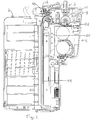
- FIG. 1 The sectional view of Fig. 1 shows a banknote validator 2 having a banknote validating head 4, and a cashbox 6 where banknotes enter through the banknote inlet 8, pass through the processing channel 10 to the curved transition 12, and if authenticated, are driven to overlap with the stacking port 40 of the cashbox 6.
- the arrangement of Fig. 1 has a particular drive arrangement and banknote processing pathway which distinguishes it from the prior art. It can be seen from a review of Figures 2 and 3 that the curved transition 12 which forms part of the banknote processing channel is defined between a portion of the validating head 4 and an end portion of the cashbox 6. This curved transition allows an authenticated banknote to be driven and positioned in front of a port of a cashbox.
- the curved transition essentially joins the two straight segments that have a generally 90° orientation.
- the curved transition is defined by a portion of the cashbox and a portion of the validating head. This is in contrast to prior art arrangements where the curved transition is entirely formed within the validating head and the cashbox abuts with an offset discharge from the validating head after the banknote has been processed through the curved transition.
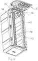
- the validating head 4 includes an outside portion 5 that defines part of the exterior of the curved transition 12.
- the one end 15 of the cashbox 6 defines a second portion of the curved transition.
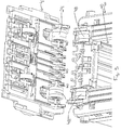
- the cashbox includes a series of interfitting or overlapping surfaces 62 as shown in Fig. 3 which cooperate with the interfitting surfaces 60 of the outside portion 5 of the validating head 4. These interfitting surfaces form stationary parts of the exterior surface of the curved transition.
- the outside portion 5 of the validating head 4 includes two cooperating responsive rollers 24 that engage the drive roller 22 shown in Fig. 1 .
- a banknote passing through the banknote channel and the curved transition is engaged by each of the drive rollers 22 and the cooperating responsive rollers 24 as part of the validating head and the cooperating responsive rollers 48 that are supported in the cashbox.
- the drive roller 22 is engaged by the responsive roller 24 and the responsive roller 48 of the cashbox.
- the drive roller 22 is oversized relative to the responsive rollers and preferably is of a diameter at least twice the diameter of the responsive rollers. With this arrangement the drive belts and the drive rollers drive the banknote throughout the curved transition.
- Figures 5 and 6 show a further feature of the present invention.
- the drive roller 22 is actually a combination drive roller having a drive roller segment 34 which engages roller segment 26 of the cooperating responsive rollers 24 and 48.
- the drive roller 22 also includes a belt drive gear segment 36 shown in Fig. 7 that cooperates and drives the drive belt 30. With this structure, both the drive belt 30 (and there are a pair of drive belts 30 provided either side of the banknote channel) and the drive roller segment 34 control the banknote as it passes through the curved transition.
- the drive belts 30 continue to drive the banknote downwardly as these drive belts are positioned either side of the stacking port 40 in the banknote cassette. It can also be appreciated that the drive roller segments of the drive rollers also force a banknote downwardly so that it can assume an overlapped position with the stacking port 40 of the cashbox 6 to allow stacking therein. With banknotes of different widths, this has been effective in reducing jamming events.
- the outside position of the banknote drive belts is preferred as they extend either side of the port 40.
- a return roller for each drive belt is generally shown as 49.
- Fig. 5 shows a pusher plate 70 that includes its own motor for forcing of the pusher plate through the stacking port 40 and any banknote in front of the stacking port to push a banknote into the cashbox.
- the curved transition is formed between the cashbox and the banknote validating head.
- the inner portion of the curved transition is defined in the validating head by the banknote channel and the drive rollers 22 and the drive belts.
- the outer portion of the curved transition is partially defined by the validating head (i.e. the outside portion 5) and the one end of the cashbox such that a banknote is only prone to jamming in the curved transition and the cashbox and validating head have a pass off point that is collectively defined within the curved transition.
- the drive roller 22 By positioning the drive roller 22 in the curved transition and of a diameter to allow it to engage the banknote as it enters the curved transition as well as when it leaves the curved transition, the drive roller maintains control over the banknote and provides an effective hand off as the processing channel of the banknote on the exterior thereof changes from the banknote validating head to the cashbox.
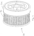
- FIG. 7 is a perspective view of the drive roller 22 which includes the gear drive segment 36 for engaging teeth on the back surface of the drive belts as well as a drive roller segment 34.
- This drive roller segment can be of an appropriate rubber material or other suitable material for engaging the banknote as it passes through the curved transition.
- the responsive roller 34 and the responsive roller 48 are preferably of the same design as shown in Fig. 8 .
- a drive roller segment 34 engages the opposite roller segment 26 and a spaced belt drive gear segment 36. These elements cooperate with the outer surface of the belt drive to appropriately drive the banknote with rotation of the roller. It can be seen that the two segments 34 and 36 are separated by a center recessed portion 35. This is preferred to allow each of the segments 34 and 36 to respectively function independently of one another although tied to the rotation of the roller.
Landscapes
- Physics & Mathematics (AREA)
- General Physics & Mathematics (AREA)
- Pile Receivers (AREA)
- Delivering By Means Of Belts And Rollers (AREA)
- Sheets, Magazines, And Separation Thereof (AREA)
Description
- The present invention relates to banknote validators having an associated cashbox and in particular to the connection between the cashbox and the banknote validator allowing banknotes to pass from the validator to the cashbox.
- Banknote validators with locking banknote cassettes or non locking cashboxes are well known and have particular application for standalone payment systems where there may or may not be security personnel present. Prior art is disclosed in
WO2009/003152A ,WO2006/0099725A US2013/0140756A .US2013/0140756A discloses a medium storage box with an integrated pick up roller.WO2009/003152A andWO2006/099725A disclose devices for use with vending machines and in exchange for goods or services. - Banknote validators and associated cashboxes for gaming machines and other applications where the value of the accumulated banknotes is relatively high, typically use a locking banknote cassette. In lower value applications such as vending machine applications, the value of accumulated banknotes received as part of the payment process is significantly less and a more cost effective arrangement of the banknote validator and cashbox is often required. For vending machine applications, it is known to use a plastic cashbox and it is also known to use a plastic cashbox with an open port. This simplified plastic cashbox is significantly less secure relative to a locked banknote cassette however it provides a low cost system. The open port plastic cashbox is typically used where the denomination of the currency being accumulated is relatively low and/or the operator demands a price point for the combination banknote validator and cashbox that is particularly aggressive.
- The present invention relates to a banknote validator having a cashbox of the open port type that has improved properties reducing the possibility of banknote jamming when passed from the validator to the cashbox.
- In banknote validators and plastic cashboxes, the cashbox is generally connected to the banknote validator for feeding of the banknote along one face of the cashbox to overlap with the open port. The banknote is appropriately positioned by the banknote validator in front of the open port and a stacking mechanism forces the banknote through the port and into the cashbox. Typically a banknote validator has an initial banknote evaluating channel of a first generally straight orientation connected to a curved transition followed by a second generally straight segment having a direction generally perpendicular to the first direction. The curved transition is normally a smooth curve defined entirely by the banknote validator and guides the banknote through the change in direction of travel and connecting with an outlet of the validator. The cashbox is then positioned adjacent the outlet and the banknote is moved or passed along a front face of the banknote receiving port in the cashbox.
- With the prior art arrangement described above, a banknote can become jammed in the banknote validator or at the junction of the cashbox and the banknote validator. Banknote validators can include various arrangements including software arrangements for controlling the drive of the banknote validator to assist in clearing of jammed banknotes, however jamming of banknotes remains a significant problem as the banknote validator is forced to a service required condition. This outage in service typically reduces sales and can frustrate both customers and the service providers.
- It is desired to provide an improved arrangement for processing of banknotes and stacking of the banknotes in a cost efficient and reliable arrangement.
- A banknote validator according to the present invention comprises a validating head having a banknote processing channel for assessing the authenticity of banknotes and a releasable cashbox connected to the validating head for stacking authenticated banknotes. The validating head includes a banknote inlet at one end of the banknote processing channel and a banknote outlet at an opposite end of the banknote channel. The banknote outlet cooperates with an end of the cashbox to collectively define a curved transition guiding an authenticated banknote through an angle of at least 90° leading to a stacking port in a side of the cashbox. The cashbox and validating head have interfitting surfaces collectively defining an outside guide structure of the curved transition when the cashbox is secured to the validating head. A drive arrangement drives banknotes through the banknote processing channel, and if authenticated, through the curved transition to the stacking port. A stacking mechanism is provided for selectively pushing a banknote through the stacking port and into the cashbox.
- In a preferred aspect of the invention the banknote validator has a particular drive arrangement that includes two lead drive rollers located in the validating head and defining a portion of the curved transition. The drive arrangement further includes cooperating responsive rollers on opposite sides of the processing channel on a front side of the curved transition and a pair of downstream responsive rollers supported in the cashbox adjacent a discharge of the curved transition. Each of these responsive rollers cooperate with the associated lead drive rollers to engage and guide a banknote towards the stacking port of the cashbox.
- Preferred embodiments of the invention are shown in the drawings wherein:
-
Fig. 1 is a vertical sectional view through a banknote validating head and the connected cashbox showing the cooperation of these components and in particular the cooperation defining the curved transition for the banknote drive path; -
Fig. 2 is a partial perspective view showing the open port of a cashbox in combination with a top member of the validating head illustrating the guide surface at the curved transition; -
Fig. 3 is a partial perspective view showing further details of the particular cooperation of the components shown inFig. 2 ; -
Fig. 4 is a partial sectional view showing the outer components and their cooperation to form the curved transition; -
Fig. 5 is a front view showing the portion of the validating head opposite the port in the cashbox; -
Fig. 6 is a partial perspective view showing the interior surface of the curved transition; -
Fig. 7 is a perspective view of the lead drive roller; and -
Fig. 8 is a perspective view of the responsive roller. - The sectional view of
Fig. 1 shows abanknote validator 2 having a banknote validating head 4, and acashbox 6 where banknotes enter through thebanknote inlet 8, pass through theprocessing channel 10 to thecurved transition 12, and if authenticated, are driven to overlap with thestacking port 40 of thecashbox 6. The arrangement ofFig. 1 has a particular drive arrangement and banknote processing pathway which distinguishes it from the prior art. It can be seen from a review ofFigures 2 and3 that thecurved transition 12 which forms part of the banknote processing channel is defined between a portion of the validating head 4 and an end portion of thecashbox 6. This curved transition allows an authenticated banknote to be driven and positioned in front of a port of a cashbox. The curved transition essentially joins the two straight segments that have a generally 90° orientation. - The curved transition is defined by a portion of the cashbox and a portion of the validating head. This is in contrast to prior art arrangements where the curved transition is entirely formed within the validating head and the cashbox abuts with an offset discharge from the validating head after the banknote has been processed through the curved transition.
- It has been found that banknotes may become jammed or lodged at a curved transition in the banknote processing path and/or at the connection to the cashbox. In contrast to the prior art arrangement, the curved transition of the present system is collectively defined between the cashbox and the validating head and thus the separate interface between the cashbox and the validating head is avoided. This reduces the number of locations where a banknote may become jammed and the arrangement has been found to be more reliable.
- As seen in
Fig. 2 , the validating head 4 includes anoutside portion 5 that defines part of the exterior of thecurved transition 12. The oneend 15 of thecashbox 6 defines a second portion of the curved transition. Basically the cashbox includes a series of interfitting or overlappingsurfaces 62 as shown inFig. 3 which cooperate with the interfittingsurfaces 60 of theoutside portion 5 of the validating head 4. These interfitting surfaces form stationary parts of the exterior surface of the curved transition. - It can also be seen in
Fig. 3 that theoutside portion 5 of the validating head 4 includes two cooperatingresponsive rollers 24 that engage thedrive roller 22 shown inFig. 1 . Basically there are 2 drive rollers on either side of the validating head and positioned within the curved transition as best shown inFig. 1 . A banknote passing through the banknote channel and the curved transition is engaged by each of thedrive rollers 22 and the cooperatingresponsive rollers 24 as part of the validating head and the cooperatingresponsive rollers 48 that are supported in the cashbox. As illustrated in the sectional view ofFig. 1 , thedrive roller 22 is engaged by theresponsive roller 24 and theresponsive roller 48 of the cashbox. With this arrangement, a banknote that is approaching the curved transition is initially engaged in the gap between theresponsive roller 24 and thedrive roller 22 and the associated drive belt. The banknote is driven through the curved transition and subsequently engaged between theresponsive roller 48 and thedrive roller 22. This arrangement for controlling of the banknote as it passes through the curved transition has proven to be very effective. With this arrangement the cashbox forms the second portion of the curved transition in combination with an inner surface of the validating head 4. - The
drive roller 22 is oversized relative to the responsive rollers and preferably is of a diameter at least twice the diameter of the responsive rollers. With this arrangement the drive belts and the drive rollers drive the banknote throughout the curved transition.Figures 5 and6 show a further feature of the present invention. Thedrive roller 22 is actually a combination drive roller having adrive roller segment 34 which engagesroller segment 26 of the cooperatingresponsive rollers drive roller 22 also includes a beltdrive gear segment 36 shown inFig. 7 that cooperates and drives thedrive belt 30. With this structure, both the drive belt 30 (and there are a pair ofdrive belts 30 provided either side of the banknote channel) and thedrive roller segment 34 control the banknote as it passes through the curved transition. At the discharge side of the curved transition, thedrive belts 30 continue to drive the banknote downwardly as these drive belts are positioned either side of the stackingport 40 in the banknote cassette. It can also be appreciated that the drive roller segments of the drive rollers also force a banknote downwardly so that it can assume an overlapped position with the stackingport 40 of thecashbox 6 to allow stacking therein. With banknotes of different widths, this has been effective in reducing jamming events. The outside position of the banknote drive belts is preferred as they extend either side of theport 40. A return roller for each drive belt is generally shown as 49. -
Fig. 5 shows apusher plate 70 that includes its own motor for forcing of the pusher plate through the stackingport 40 and any banknote in front of the stacking port to push a banknote into the cashbox. - With the present structure, the curved transition is formed between the cashbox and the banknote validating head. The inner portion of the curved transition is defined in the validating head by the banknote channel and the
drive rollers 22 and the drive belts. The outer portion of the curved transition is partially defined by the validating head (i.e. the outside portion 5) and the one end of the cashbox such that a banknote is only prone to jamming in the curved transition and the cashbox and validating head have a pass off point that is collectively defined within the curved transition. By positioning thedrive roller 22 in the curved transition and of a diameter to allow it to engage the banknote as it enters the curved transition as well as when it leaves the curved transition, the drive roller maintains control over the banknote and provides an effective hand off as the processing channel of the banknote on the exterior thereof changes from the banknote validating head to the cashbox. - The particular cooperation of the elements in the interlapping surfaces or fingers at the curved transition to collectively form the curved transition reduces jamming and effectively controls the banknote as it passes between the validating head and the cashbox. This arrangement, particularly in combination with the double drive arrangement (rollers and drive belts), provides increased reliability.
-
Figures 7 and8 show additional details of the drive roller and the cooperating responsive roller.Fig. 7 is a perspective view of thedrive roller 22 which includes thegear drive segment 36 for engaging teeth on the back surface of the drive belts as well as adrive roller segment 34. This drive roller segment can be of an appropriate rubber material or other suitable material for engaging the banknote as it passes through the curved transition. - The
responsive roller 34 and theresponsive roller 48 are preferably of the same design as shown inFig. 8 . Adrive roller segment 34 engages theopposite roller segment 26 and a spaced beltdrive gear segment 36. These elements cooperate with the outer surface of the belt drive to appropriately drive the banknote with rotation of the roller. It can be seen that the twosegments portion 35. This is preferred to allow each of thesegments - Although various preferred embodiments of the present invention have been described herein in detail, it will be appreciated by those skilled in the art, that variations may be made thereto without departing from the invention as defined in the appended claims.
Claims (8)
- A banknote validator (2) comprisinga validating head (4) having a banknote processing channel (10) for assessing the authenticity of banknotes and a releasable cashbox (6) connected to said validating head (4) for stacking authenticated banknotes; said validating head (4) including a banknote inlet (8) at one end of said banknote processing channel (10) and a banknote outlet at an opposite end of said banknote channel (10), said banknote outlet cooperating with an end of said cashbox (6) to collectively define a curved transition (12) guiding an authenticated banknote through an angle of at least 60 degrees leading to a stacking port (40) in a side of said cashbox (6);said cashbox (6) and said validating head (4) each have interfitting surfaces (60, 62) collectively defining an outside guide structure of said curved transition (12) when said cashbox (6) is secured to said validating head (4);a drive arrangement driving banknotes through said banknote processing channel (10) and if authenticated through said curved transition (12) to said stacking port (40); anda stacking mechanism for selectively pushing a banknote through said stacking port (40) and into said cashbox (6).
- The banknote validator as claimed in claim 1 wherein said drive arrangement includes two lead drive rollers (22) located in said validating head (4) defining a portion of an inside surface of said curved transition (12), and wherein each of said lead drive rollers (22) include a cooperating responsive roller (24) on an opposite side of said processing channel (10) and each of said cooperating responsive rollers include a downstream roller (48) supported in said cashbox (6) adjacent said curved transition (12).
- The banknote validator as claimed in claim 2 wherein each of said cooperating responsive rollers supported in said cashbox (6) are located to form part of said curved transition (12), and optional wherein said angle of said curved transition is approximately 90 degrees.
- The banknote validator as claimed in claim 2 wherein each of said downstream rollers additionally includes a drive belt (30) positioned to engage and drive an authenticated banknote at least from said curved transition (12) to a position in front of said stacking port (40) of said cashbox (6).
- The banknote validator as claimed in claim 4 wherein each drive belt (30) is positioned to engage and drive an authenticated banknote through said curved transition (12) to the position in front of said stacking port (40).
- The banknote validator as claimed in claim 4 or claim 5 wherein each drive belt (30) includes a drive gear connected to and rotated with rotation of the associated downstream roller.
- The banknote validator as claimed in claim 6 wherein each responsive roller in said cashbox (6) is a double roller with a first roller segment (36) cooperating with said drive belt (30) and a second roller segment (34) cooperating with said downstream roller to engage and drive an authenticated banknote.
- The banknote validator as claimed in claim 7 wherein each double roller includes an inwardly recessed portion (35) separating said first and second roller segments (34, 36), and optionally
wherein said first and second roller segments and said inwardly recessed portion of each double roller are an integral component.
Priority Applications (1)
| Application Number | Priority Date | Filing Date | Title |
|---|---|---|---|
| EP21209305.8A EP3985625A1 (en) | 2013-11-04 | 2014-10-31 | Banknote validator with cashbox |
Applications Claiming Priority (2)
| Application Number | Priority Date | Filing Date | Title |
|---|---|---|---|
| CA2832600A CA2832600A1 (en) | 2013-11-04 | 2013-11-04 | Banknote validator with cashbox |
| PCT/CA2014/000782 WO2015061887A1 (en) | 2013-11-04 | 2014-10-31 | Banknote validator with cashbox |
Related Child Applications (1)
| Application Number | Title | Priority Date | Filing Date |
|---|---|---|---|
| EP21209305.8A Division EP3985625A1 (en) | 2013-11-04 | 2014-10-31 | Banknote validator with cashbox |
Publications (3)
| Publication Number | Publication Date |
|---|---|
| EP3066649A1 EP3066649A1 (en) | 2016-09-14 |
| EP3066649A4 EP3066649A4 (en) | 2017-10-25 |
| EP3066649B1 true EP3066649B1 (en) | 2021-12-01 |
Family
ID=53003040
Family Applications (2)
| Application Number | Title | Priority Date | Filing Date |
|---|---|---|---|
| EP21209305.8A Withdrawn EP3985625A1 (en) | 2013-11-04 | 2014-10-31 | Banknote validator with cashbox |
| EP14858912.0A Active EP3066649B1 (en) | 2013-11-04 | 2014-10-31 | Banknote validator with cashbox |
Family Applications Before (1)
| Application Number | Title | Priority Date | Filing Date |
|---|---|---|---|
| EP21209305.8A Withdrawn EP3985625A1 (en) | 2013-11-04 | 2014-10-31 | Banknote validator with cashbox |
Country Status (5)
| Country | Link |
|---|---|
| EP (2) | EP3985625A1 (en) |
| CN (2) | CN105814613B (en) |
| CA (1) | CA2832600A1 (en) |
| ES (1) | ES2906557T3 (en) |
| WO (1) | WO2015061887A1 (en) |
Families Citing this family (2)
| Publication number | Priority date | Publication date | Assignee | Title |
|---|---|---|---|---|
| CN106355747B (en) * | 2016-09-08 | 2022-09-27 | 深圳怡化电脑股份有限公司 | Waste paper money box driving mechanism, financial self-service equipment and waste paper money box paper money processing method |
| CN107833355B (en) * | 2017-11-22 | 2023-12-26 | 深圳怡化电脑股份有限公司 | Self-service equipment and medium transmission system thereof |
Citations (1)
| Publication number | Priority date | Publication date | Assignee | Title |
|---|---|---|---|---|
| WO2009003152A1 (en) * | 2007-06-27 | 2008-12-31 | Mei, Inc. | Document handling device |
Family Cites Families (19)
| Publication number | Priority date | Publication date | Assignee | Title |
|---|---|---|---|---|
| DE4005291C2 (en) * | 1989-02-22 | 1995-06-29 | Nsm Ag | Device for checking and storing banknotes in a self-cashing machine |
| US5411249A (en) * | 1994-01-10 | 1995-05-02 | Mars Incorporated | Currency validator and cassette transport alignment apparatus |
| US5632367A (en) * | 1995-01-23 | 1997-05-27 | Mars, Incorporated | Validation housing for a bill validator made by a two shot molding process |
| US5803227A (en) * | 1995-06-06 | 1998-09-08 | International Game Technology | Bill stacker |
| US5756985A (en) * | 1996-04-04 | 1998-05-26 | Coin Acceptors, Inc. | Cash box system for bill validator |
| US6712352B2 (en) * | 2000-10-17 | 2004-03-30 | Mars Incorporated | Lockable removable cassette |
| DE10210687A1 (en) * | 2002-03-12 | 2003-10-09 | Giesecke & Devrient Gmbh | Device for processing banknotes |
| DE102004059951A1 (en) * | 2004-08-17 | 2006-02-23 | Giesecke & Devrient Gmbh | Device for examining documents |
| CA2502344A1 (en) * | 2005-03-24 | 2006-09-24 | Cashcode Company Inc. | Validator with recycling cassette and stacker |
| US20070009382A1 (en) * | 2005-07-05 | 2007-01-11 | William Bedingham | Heating element for a rotating multiplex fluorescence detection device |
| JP4710727B2 (en) * | 2006-06-09 | 2011-06-29 | 沖電気工業株式会社 | Deposit bill handling mechanism |
| CN201017364Y (en) * | 2007-02-12 | 2008-02-06 | 北京兆维科技股份有限公司 | Bank-note identifier having improvement detecting channel |
| CN101350117B (en) * | 2008-03-11 | 2011-05-18 | 广州广电运通金融电子股份有限公司 | Bundling money-discharging machine |
| WO2010108536A1 (en) * | 2009-03-23 | 2010-09-30 | Talaris Limited | Document handling apparatus |
| JP5216805B2 (en) * | 2010-04-30 | 2013-06-19 | 日立オムロンターミナルソリューションズ株式会社 | Paper sheet processing equipment |
| CN102289861B (en) * | 2011-08-17 | 2013-01-30 | 易程(苏州)电子科技股份有限公司 | Paper money collecting machine capable of automatically feeding whole stack of paper money simultaneously |
| CN103130009B (en) * | 2011-11-29 | 2016-04-06 | 恒银金融科技股份有限公司 | A kind of individual banknotes connecting gear |
| US9346639B2 (en) * | 2011-12-02 | 2016-05-24 | Lg Cns Co., Ltd. | Medium storage box, medium handling apparatus and financial device |
| RU2473129C1 (en) * | 2011-12-14 | 2013-01-20 | Общество С Ограниченной Ответственностью "Конструкторское Бюро "Дорс" (Ооо "Кб "Дорс") | Device for processing banknotes (versions) |
-
2013
- 2013-11-04 CA CA2832600A patent/CA2832600A1/en not_active Abandoned
-
2014
- 2014-10-31 WO PCT/CA2014/000782 patent/WO2015061887A1/en not_active Ceased
- 2014-10-31 CN CN201480066766.8A patent/CN105814613B/en active Active
- 2014-10-31 EP EP21209305.8A patent/EP3985625A1/en not_active Withdrawn
- 2014-10-31 CN CN202010586950.2A patent/CN111754676B/en active Active
- 2014-10-31 ES ES14858912T patent/ES2906557T3/en active Active
- 2014-10-31 EP EP14858912.0A patent/EP3066649B1/en active Active
Patent Citations (1)
| Publication number | Priority date | Publication date | Assignee | Title |
|---|---|---|---|---|
| WO2009003152A1 (en) * | 2007-06-27 | 2008-12-31 | Mei, Inc. | Document handling device |
Also Published As
| Publication number | Publication date |
|---|---|
| CN111754676A (en) | 2020-10-09 |
| CN105814613A (en) | 2016-07-27 |
| EP3066649A1 (en) | 2016-09-14 |
| EP3066649A4 (en) | 2017-10-25 |
| EP3985625A1 (en) | 2022-04-20 |
| CA2832600A1 (en) | 2015-05-04 |
| ES2906557T3 (en) | 2022-04-19 |
| CN111754676B (en) | 2022-05-24 |
| CN105814613B (en) | 2020-07-21 |
| WO2015061887A1 (en) | 2015-05-07 |
Similar Documents
| Publication | Publication Date | Title |
|---|---|---|
| CN101147176B (en) | Banknote processing device | |
| US9053597B1 (en) | Banknote validator | |
| CN101256692B (en) | paper output device | |
| US9183691B2 (en) | Banknote pay-in/pay-out device and banknote processing machine | |
| KR101147028B1 (en) | Bill receiving and paying apparatus, automated teller machine, bill stacking method, and computer-readable media storing bill stacking program | |
| KR101162622B1 (en) | Bill depositing/dispensing apparatus | |
| US20180170697A1 (en) | Medium conveyance device and medium transaction device | |
| EP3985625A1 (en) | Banknote validator with cashbox | |
| JP6064786B2 (en) | Medium stacking apparatus and medium processing apparatus | |
| JP4178132B2 (en) | Paper sheet stacking and separating device | |
| JP6227397B2 (en) | Banknote handling equipment | |
| WO2015145854A1 (en) | Paper currency processing device | |
| JP5003267B2 (en) | Banknote deposit and withdrawal machine | |
| KR101609458B1 (en) | Coin handling apparatus and financial device | |
| JP2007220031A (en) | Bill handling apparatus | |
| JP2016199380A (en) | Medium processor | |
| JP7465130B2 (en) | Sheet processing apparatus, sheet processing system, and sheet processing method | |
| EP3321893B1 (en) | Paper sheet storage cassette and paper sheet handling machine | |
| CN105793177B (en) | Paper transport unit and paper identification device | |
| JP2009007113A (en) | Paper sheet feeding device | |
| JP2024108691A (en) | Banknote Processing Device | |
| JP2023034937A (en) | media handling unit | |
| JP5544841B2 (en) | Coin handling machine | |
| JP2019175079A (en) | Coin processing machine | |
| JP2017102682A (en) | Banknote handling equipment |
Legal Events
| Date | Code | Title | Description |
|---|---|---|---|
| PUAI | Public reference made under article 153(3) epc to a published international application that has entered the european phase |
Free format text: ORIGINAL CODE: 0009012 |
|
| 17P | Request for examination filed |
Effective date: 20160602 |
|
| AK | Designated contracting states |
Kind code of ref document: A1 Designated state(s): AL AT BE BG CH CY CZ DE DK EE ES FI FR GB GR HR HU IE IS IT LI LT LU LV MC MK MT NL NO PL PT RO RS SE SI SK SM TR |
|
| AX | Request for extension of the european patent |
Extension state: BA ME |
|
| DAX | Request for extension of the european patent (deleted) | ||
| A4 | Supplementary search report drawn up and despatched |
Effective date: 20170926 |
|
| RIC1 | Information provided on ipc code assigned before grant |
Ipc: G07D 7/00 20160101AFI20170920BHEP Ipc: G07D 11/00 20060101ALI20170920BHEP |
|
| STAA | Information on the status of an ep patent application or granted ep patent |
Free format text: STATUS: EXAMINATION IS IN PROGRESS |
|
| 17Q | First examination report despatched |
Effective date: 20171220 |
|
| GRAP | Despatch of communication of intention to grant a patent |
Free format text: ORIGINAL CODE: EPIDOSNIGR1 |
|
| STAA | Information on the status of an ep patent application or granted ep patent |
Free format text: STATUS: GRANT OF PATENT IS INTENDED |
|
| INTG | Intention to grant announced |
Effective date: 20210611 |
|
| GRAS | Grant fee paid |
Free format text: ORIGINAL CODE: EPIDOSNIGR3 |
|
| GRAA | (expected) grant |
Free format text: ORIGINAL CODE: 0009210 |
|
| STAA | Information on the status of an ep patent application or granted ep patent |
Free format text: STATUS: THE PATENT HAS BEEN GRANTED |
|
| AK | Designated contracting states |
Kind code of ref document: B1 Designated state(s): AL AT BE BG CH CY CZ DE DK EE ES FI FR GB GR HR HU IE IS IT LI LT LU LV MC MK MT NL NO PL PT RO RS SE SI SK SM TR |
|
| REG | Reference to a national code |
Ref country code: GB Ref legal event code: FG4D |
|
| REG | Reference to a national code |
Ref country code: AT Ref legal event code: REF Ref document number: 1452528 Country of ref document: AT Kind code of ref document: T Effective date: 20211215 Ref country code: CH Ref legal event code: EP |
|
| REG | Reference to a national code |
Ref country code: IE Ref legal event code: FG4D |
|
| REG | Reference to a national code |
Ref country code: DE Ref legal event code: R096 Ref document number: 602014081571 Country of ref document: DE |
|
| REG | Reference to a national code |
Ref country code: LT Ref legal event code: MG9D |
|
| REG | Reference to a national code |
Ref country code: NL Ref legal event code: MP Effective date: 20211201 |
|
| REG | Reference to a national code |
Ref country code: AT Ref legal event code: MK05 Ref document number: 1452528 Country of ref document: AT Kind code of ref document: T Effective date: 20211201 |
|
| REG | Reference to a national code |
Ref country code: ES Ref legal event code: FG2A Ref document number: 2906557 Country of ref document: ES Kind code of ref document: T3 Effective date: 20220419 |
|
| PG25 | Lapsed in a contracting state [announced via postgrant information from national office to epo] |
Ref country code: RS Free format text: LAPSE BECAUSE OF FAILURE TO SUBMIT A TRANSLATION OF THE DESCRIPTION OR TO PAY THE FEE WITHIN THE PRESCRIBED TIME-LIMIT Effective date: 20211201 Ref country code: LT Free format text: LAPSE BECAUSE OF FAILURE TO SUBMIT A TRANSLATION OF THE DESCRIPTION OR TO PAY THE FEE WITHIN THE PRESCRIBED TIME-LIMIT Effective date: 20211201 Ref country code: FI Free format text: LAPSE BECAUSE OF FAILURE TO SUBMIT A TRANSLATION OF THE DESCRIPTION OR TO PAY THE FEE WITHIN THE PRESCRIBED TIME-LIMIT Effective date: 20211201 Ref country code: BG Free format text: LAPSE BECAUSE OF FAILURE TO SUBMIT A TRANSLATION OF THE DESCRIPTION OR TO PAY THE FEE WITHIN THE PRESCRIBED TIME-LIMIT Effective date: 20220301 Ref country code: AT Free format text: LAPSE BECAUSE OF FAILURE TO SUBMIT A TRANSLATION OF THE DESCRIPTION OR TO PAY THE FEE WITHIN THE PRESCRIBED TIME-LIMIT Effective date: 20211201 |
|
| PG25 | Lapsed in a contracting state [announced via postgrant information from national office to epo] |
Ref country code: SE Free format text: LAPSE BECAUSE OF FAILURE TO SUBMIT A TRANSLATION OF THE DESCRIPTION OR TO PAY THE FEE WITHIN THE PRESCRIBED TIME-LIMIT Effective date: 20211201 Ref country code: PL Free format text: LAPSE BECAUSE OF FAILURE TO SUBMIT A TRANSLATION OF THE DESCRIPTION OR TO PAY THE FEE WITHIN THE PRESCRIBED TIME-LIMIT Effective date: 20211201 Ref country code: NO Free format text: LAPSE BECAUSE OF FAILURE TO SUBMIT A TRANSLATION OF THE DESCRIPTION OR TO PAY THE FEE WITHIN THE PRESCRIBED TIME-LIMIT Effective date: 20220301 Ref country code: LV Free format text: LAPSE BECAUSE OF FAILURE TO SUBMIT A TRANSLATION OF THE DESCRIPTION OR TO PAY THE FEE WITHIN THE PRESCRIBED TIME-LIMIT Effective date: 20211201 Ref country code: HR Free format text: LAPSE BECAUSE OF FAILURE TO SUBMIT A TRANSLATION OF THE DESCRIPTION OR TO PAY THE FEE WITHIN THE PRESCRIBED TIME-LIMIT Effective date: 20211201 Ref country code: GR Free format text: LAPSE BECAUSE OF FAILURE TO SUBMIT A TRANSLATION OF THE DESCRIPTION OR TO PAY THE FEE WITHIN THE PRESCRIBED TIME-LIMIT Effective date: 20220302 |
|
| PG25 | Lapsed in a contracting state [announced via postgrant information from national office to epo] |
Ref country code: NL Free format text: LAPSE BECAUSE OF FAILURE TO SUBMIT A TRANSLATION OF THE DESCRIPTION OR TO PAY THE FEE WITHIN THE PRESCRIBED TIME-LIMIT Effective date: 20211201 |
|
| PG25 | Lapsed in a contracting state [announced via postgrant information from national office to epo] |
Ref country code: SM Free format text: LAPSE BECAUSE OF FAILURE TO SUBMIT A TRANSLATION OF THE DESCRIPTION OR TO PAY THE FEE WITHIN THE PRESCRIBED TIME-LIMIT Effective date: 20211201 Ref country code: SK Free format text: LAPSE BECAUSE OF FAILURE TO SUBMIT A TRANSLATION OF THE DESCRIPTION OR TO PAY THE FEE WITHIN THE PRESCRIBED TIME-LIMIT Effective date: 20211201 Ref country code: RO Free format text: LAPSE BECAUSE OF FAILURE TO SUBMIT A TRANSLATION OF THE DESCRIPTION OR TO PAY THE FEE WITHIN THE PRESCRIBED TIME-LIMIT Effective date: 20211201 Ref country code: PT Free format text: LAPSE BECAUSE OF FAILURE TO SUBMIT A TRANSLATION OF THE DESCRIPTION OR TO PAY THE FEE WITHIN THE PRESCRIBED TIME-LIMIT Effective date: 20220401 Ref country code: EE Free format text: LAPSE BECAUSE OF FAILURE TO SUBMIT A TRANSLATION OF THE DESCRIPTION OR TO PAY THE FEE WITHIN THE PRESCRIBED TIME-LIMIT Effective date: 20211201 Ref country code: CZ Free format text: LAPSE BECAUSE OF FAILURE TO SUBMIT A TRANSLATION OF THE DESCRIPTION OR TO PAY THE FEE WITHIN THE PRESCRIBED TIME-LIMIT Effective date: 20211201 |
|
| REG | Reference to a national code |
Ref country code: DE Ref legal event code: R097 Ref document number: 602014081571 Country of ref document: DE |
|
| PG25 | Lapsed in a contracting state [announced via postgrant information from national office to epo] |
Ref country code: IS Free format text: LAPSE BECAUSE OF FAILURE TO SUBMIT A TRANSLATION OF THE DESCRIPTION OR TO PAY THE FEE WITHIN THE PRESCRIBED TIME-LIMIT Effective date: 20220401 |
|
| PLBE | No opposition filed within time limit |
Free format text: ORIGINAL CODE: 0009261 |
|
| STAA | Information on the status of an ep patent application or granted ep patent |
Free format text: STATUS: NO OPPOSITION FILED WITHIN TIME LIMIT |
|
| PG25 | Lapsed in a contracting state [announced via postgrant information from national office to epo] |
Ref country code: DK Free format text: LAPSE BECAUSE OF FAILURE TO SUBMIT A TRANSLATION OF THE DESCRIPTION OR TO PAY THE FEE WITHIN THE PRESCRIBED TIME-LIMIT Effective date: 20211201 Ref country code: AL Free format text: LAPSE BECAUSE OF FAILURE TO SUBMIT A TRANSLATION OF THE DESCRIPTION OR TO PAY THE FEE WITHIN THE PRESCRIBED TIME-LIMIT Effective date: 20211201 |
|
| 26N | No opposition filed |
Effective date: 20220902 |
|
| REG | Reference to a national code |
Ref country code: GB Ref legal event code: 732E Free format text: REGISTERED BETWEEN 20221013 AND 20221019 |
|
| PG25 | Lapsed in a contracting state [announced via postgrant information from national office to epo] |
Ref country code: SI Free format text: LAPSE BECAUSE OF FAILURE TO SUBMIT A TRANSLATION OF THE DESCRIPTION OR TO PAY THE FEE WITHIN THE PRESCRIBED TIME-LIMIT Effective date: 20211201 |
|
| REG | Reference to a national code |
Ref country code: DE Ref legal event code: R081 Ref document number: 602014081571 Country of ref document: DE Owner name: CRANE PAYMENT INNOVATIONS, INC. (N.D.GES.D. ST, US Free format text: FORMER OWNER: CRANE CANADA CO., CONCORD, ON, CA |
|
| REG | Reference to a national code |
Ref country code: ES Ref legal event code: PC2A Owner name: CRANE PAYMENT INNOVATIONS, INC. Effective date: 20230317 |
|
| PG25 | Lapsed in a contracting state [announced via postgrant information from national office to epo] |
Ref country code: MC Free format text: LAPSE BECAUSE OF FAILURE TO SUBMIT A TRANSLATION OF THE DESCRIPTION OR TO PAY THE FEE WITHIN THE PRESCRIBED TIME-LIMIT Effective date: 20211201 |
|
| REG | Reference to a national code |
Ref country code: CH Ref legal event code: PL |
|
| P01 | Opt-out of the competence of the unified patent court (upc) registered |
Effective date: 20230420 |
|
| REG | Reference to a national code |
Ref country code: BE Ref legal event code: MM Effective date: 20221031 |
|
| PG25 | Lapsed in a contracting state [announced via postgrant information from national office to epo] |
Ref country code: LU Free format text: LAPSE BECAUSE OF NON-PAYMENT OF DUE FEES Effective date: 20221031 |
|
| PG25 | Lapsed in a contracting state [announced via postgrant information from national office to epo] |
Ref country code: LI Free format text: LAPSE BECAUSE OF NON-PAYMENT OF DUE FEES Effective date: 20221031 Ref country code: FR Free format text: LAPSE BECAUSE OF NON-PAYMENT OF DUE FEES Effective date: 20221031 Ref country code: CH Free format text: LAPSE BECAUSE OF NON-PAYMENT OF DUE FEES Effective date: 20221031 |
|
| REG | Reference to a national code |
Ref country code: DE Ref legal event code: R082 Ref document number: 602014081571 Country of ref document: DE Representative=s name: VENNER SHIPLEY GERMANY LLP, DE |
|
| PG25 | Lapsed in a contracting state [announced via postgrant information from national office to epo] |
Ref country code: BE Free format text: LAPSE BECAUSE OF NON-PAYMENT OF DUE FEES Effective date: 20221031 |
|
| PG25 | Lapsed in a contracting state [announced via postgrant information from national office to epo] |
Ref country code: IE Free format text: LAPSE BECAUSE OF NON-PAYMENT OF DUE FEES Effective date: 20221031 |
|
| PG25 | Lapsed in a contracting state [announced via postgrant information from national office to epo] |
Ref country code: HU Free format text: LAPSE BECAUSE OF FAILURE TO SUBMIT A TRANSLATION OF THE DESCRIPTION OR TO PAY THE FEE WITHIN THE PRESCRIBED TIME-LIMIT; INVALID AB INITIO Effective date: 20141031 |
|
| PG25 | Lapsed in a contracting state [announced via postgrant information from national office to epo] |
Ref country code: CY Free format text: LAPSE BECAUSE OF FAILURE TO SUBMIT A TRANSLATION OF THE DESCRIPTION OR TO PAY THE FEE WITHIN THE PRESCRIBED TIME-LIMIT Effective date: 20211201 |
|
| PG25 | Lapsed in a contracting state [announced via postgrant information from national office to epo] |
Ref country code: MK Free format text: LAPSE BECAUSE OF FAILURE TO SUBMIT A TRANSLATION OF THE DESCRIPTION OR TO PAY THE FEE WITHIN THE PRESCRIBED TIME-LIMIT Effective date: 20211201 |
|
| PG25 | Lapsed in a contracting state [announced via postgrant information from national office to epo] |
Ref country code: TR Free format text: LAPSE BECAUSE OF FAILURE TO SUBMIT A TRANSLATION OF THE DESCRIPTION OR TO PAY THE FEE WITHIN THE PRESCRIBED TIME-LIMIT Effective date: 20211201 |
|
| PG25 | Lapsed in a contracting state [announced via postgrant information from national office to epo] |
Ref country code: MT Free format text: LAPSE BECAUSE OF FAILURE TO SUBMIT A TRANSLATION OF THE DESCRIPTION OR TO PAY THE FEE WITHIN THE PRESCRIBED TIME-LIMIT Effective date: 20211201 |
|
| PGFP | Annual fee paid to national office [announced via postgrant information from national office to epo] |
Ref country code: IT Payment date: 20240910 Year of fee payment: 11 |
|
| PGFP | Annual fee paid to national office [announced via postgrant information from national office to epo] |
Ref country code: ES Payment date: 20241107 Year of fee payment: 11 |
|
| PGFP | Annual fee paid to national office [announced via postgrant information from national office to epo] |
Ref country code: GB Payment date: 20250911 Year of fee payment: 12 |
|
| PGFP | Annual fee paid to national office [announced via postgrant information from national office to epo] |
Ref country code: DE Payment date: 20250902 Year of fee payment: 12 |